1
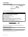
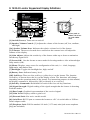
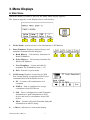
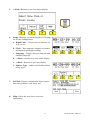
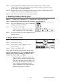
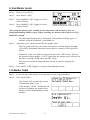
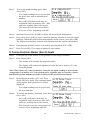
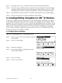
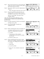
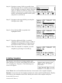
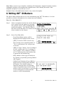
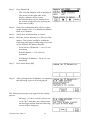
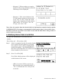
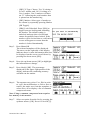
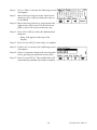
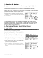
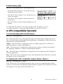
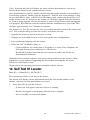
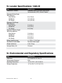
3M™ Dynatel™ Electronic Marking System Marker Locator 1420-iD Operator’s Manual 1420-iD Marker Locator 1420E-iD Marker Locator March 2014 78-8130-6741-6 Rev G 3 Contents 1. Safety Information............................................................................................. 4 A. Intended Use................................................................................................. 4 3. Quick Start......................................................................................................... 5 A. Locator Battery Installation.......................................................................... 5 B. Cleaning the Locator Unit............................................................................. 5 C. Service and Accessories................................................................................ 5 D. 1420-ID Locator Keypad Definitions........................................................... 6 3. Menu Displays................................................................................................... 7 A. Main Menu................................................................................................... 7 4. Locating 3M™ Electronic Markers and iD Markers........................................... 9 A. Activating the Marker Locate Feature (– E-Model Only)............................ 9. B. E-Model Initial Configuration (Applies only to 1420E model.)................... 9 C. Enabling/Disabling Marker Types.............................................................. 10 D. Single Marker Locate................................................................................. 10 E. Enabling/Disabling Frequencies................................................................. 11 F. iD Marker Depth.......................................................................................... 11 G. Passive Electronic Marker (Non-iD) Depth............................................... 12 5. Creating/Editing Templates for 3M™ iD Markers............................................ 13 A. Creating New Templates............................................................................. 13 B. Editing Templates....................................................................................... 15 6. Writing iD Markers.......................................................................................... 16 A. Modifying Marker Data to be Written........................................................ 17 7. Reading iD Markers......................................................................................... 19 8. Reviewing Marker Read/Write History........................................................... 19 A. Read History............................................................................................... 19 B. Write History............................................................................................... 20 9. GPS Compatibility Operation.......................................................................... 20 A. Communicating with the GPS Device........................................................ 21 B. Capturing the GPS Coordinates (Capture Mode / Mode 1)........................ 21 C. Sending iD Marker Data to GPS (Capture-Transmit Mode / Mode 2)....... 22 10. Help Mode..................................................................................................... 22 11. 3M™ Dynatel™ PC Tool Kit and Locator Software Upgrades........................ 22 12. Self Test of Locator........................................................................................ 23 13. Locator Specifications.................................................................................... 24 2 78-8130-6741-6 Rev G Congratulations! You have just purchased one of the finest, most advanced Electronic Marker locating devices available today! The 3M™ Dynatel™ Marker Locators 1420-iD and 1420E-iD are designed with all of the functionality of previous Dynatel models, with the enhanced capability to read from, and write user information into, 3M iD Markers. Information such as a pre-programmed unique identification number, facility data, application type, placement date and other details can all be read, stored and downloaded to your PC for enhanced resource management with this revolutionary equipment. The Dynatel Marker Locators 1420-iD and 1420E-iD will also search for two different types of utility markers simultaneously. When used in conjunction with a hand-held GPS device, the ability to transmit path and marker coordinates multiplies the potential to the mapping industry. This equipment provides a simple system for mapping utility information directly into CAD and GIS systems. 3M is dedicated to bringing you premium equipment with outstanding reliability, backed by one of the best warranties in the business and outstanding service. Visit our website at http://www.3M.com/dynatel for more application notes and product information. Statement of Conformity "Hereby, 3M Company declares that this Underground Locating Product is incompliance with the essential requirements and other relevant provisions of Directive 1999/5/EC." www.3m.com/market/telecom/access/conformity/ 78-8130-6741-6 Rev G 3 1. Safety Information Please read, understand and follow all safety information contained in these instructions prior to the use of the 3M 1420-iD and 1420E-iD Marker Locator. Retain these instructions for future reference. A. Intended Use The 3M™ Dynatel™ 1420-iD and 1420E-iD Electronic Marker Locators are designed and tested for use in locating 3M buried markers. 3M markers are used to identify buried utilities and structures. The system must be installed as specified in the 3M Electronic Marker System 1420-iD Locator Operator's Manual. They have not been evaluated for other uses or locations. If this equipment is used in a manner not specied by 3M, the protections provided by the equipment may be impaired. Explanation of Signal Word Consequences !Warning: Indicates hazardous situation which if not avoided, could result in death or serious injury. !Caution: Indicates hazardous situation which if not avoided, could result in minor or moderate injury. Explanation of Product Safety Label Symbols Do not throw away in normal trash. F Warning: Risk of electric shock It is unlawful to operate this unit in any country with a configuration setting that is not specific to that country. In order to prevent the user from operating this unit with a configuration setting that is not specific to the country where it is operated, this unit is equipped with configuration software for installing country specific configurations. Please refer to the initial configuration setup sheet. 4 78-8130-6741-6 Rev G 2. Quick Start A. Locator Battery Installation 8 'AA' (LR 6) size Alkaline Batteries 1. Twist cap to open battery compartment. 2. Slide battery compartment out of handle. ! Caution To reduce the risks associated with fire and explosion: • Do not short, excessively heat, or dispose of batteries in fire. • Install batteries with proper polarity. • Use only Alkaline "AA" (LR 6) sized batteries. • Do not charge batteries. • Do not use leaking batteries. To reduce the risks associated with environmental contamination: • Dispose of batteries and electronic components in accordance with all regulations. • Ensure batteries are installed with correct polarity. • Always remove batteries when storing the units for long periods of time. The locator batteries are tested for two seconds every time the unit is turned on. The Bar Graph [11] on the display screen will fill to the relative battery level. The Battery Icon [8] on the Locate Screen will continuously indicate the battery level. B. Cleaning the Locator Unit To clean the locator unit, wipe with a damp cloth. C. Service and Accessories Information regarding service, accessories, or replacement parts can be obtained by contacting 3M at 1-800-426-8688 in the U.S., or by contacting your local 3M Sales Office or 3M Sales Representative outside of the U.S. 78-8130-6741-6 Rev G 5 D. 1420-iD Locator Keypad and Display Definitions 2A 8 10 11 12 3 13 14 15 7 9 1 6 2 4 5 [1] On/Off (Power): Turns unit on and off. Access panel on bottom side of locator under rubber cover [2] S peaker Volume Control: [2] Adjusts the volume of the locator (off, low, medium, and high). [2A] Speaker Volume Icon: Indicates the relative volume level of the locator. [3] Contrast: The arrows located above and below the contrast icon will adjust the contrast of the display. [4] Gain Adjust: Adjusts the sensitivity of the locator either up or down to maintain a satisfactory signal level. [5] Locate/OK: Sets the locator to trace mode for locating markers. Also acknowledges setup entries (OK). [6] Menu: Displays setup screen for configuration of the unit, i.e.: clock, language, depth units, and marker data. [7] Backlight: Toggles the backlight low, high, and off. [8] Battery Icon: Indicates battery level. [SK] Soft Keys: There are four soft keys (yellow keys) on the locator. The function of each key is shown above the key on the display screen. The functions will change, depending on the operation mode of the locator. For instruction purposes in this manual, the display command is followed by [SK] to identify it as a soft key. [9] Soft Key Commands: Definitions for each of the four soft key functions. [10] Signal Strength: Digital reading of the signal strength that the locator is detecting from the marker. [11] Bar Graph: Graphical representation of the received signal. [12] Gain Level: Displays relative gain level. [13] External Jack: Not active on this model. [l4] Serial Port: RS232 port to connect the locator to a PC via serial cable or USB-toSerial Adapter cable. [15] Earphone Jack: Will fit standard 1/8 inch (3.175 mm) mini-jack mono earphone plug (not included). 6 78-8130-6741-6 Rev G 3. Menu Displays A. Main Menu When the Menu [6] button is pressed, the Main Menu display appears. The function appears on the display above each soft key. 1. Write Mode: System used to write information to iD Markers 2. Data/Template: Displays marker history and template creation/selection displays: a. Read History – 100 memory locations for Read iD Markers b. Write History – 100 memory locations for Written iD Markers c. User Templates – Create and edit iD templates for iD Markers (max = 32) d. Exit – Returns to prior menu. 3. COM Setup: Displays second level COM Port setting display to configure RS232 port communication with different devices – a. PC – Locator will communicate to a computer b. NMEA – Port is configured to accept coordinates from GPS device c. GIS – Port is configured to send iD marker information or path information to GPS device and receive coordinates from GPS device. d. PDA – Locator will send iD marker and path information in ASCII string. 4. >>More: Advances to next menu display 78-8130-6741-6 Rev G 7 5. <<Back: Returns to previous menu display 6. Setup: Displays second and third level displays for locator configuration a. Depth Units – Choose unit of measure; in, ft-in, or cm b. Clock – Date and time stamped on marker information and depth readings. c. Language – Toggles between English and alternate language d. >>More - Advances to next menu display e. <<Back - Returns to previous display f. Marker Type – enable and disable marker utility types 7. Self Test: Displays information about locator unit and performs a self check test 8. Help: Offers the user basic on-screen instructions 8 78-8130-6741-6 Rev G 4. Locating 3M™ Electronic Markers and 3M™ iD Markers A. E-Model Initial Configuration (Applies only to 1420E model.) Attention: All E-Model (Export) iD Locators must run the initial configuration setup found in the 3M™ Dynatel™ Locator PC Tools software. The 3M™ Dynatel™ PC Tools software is available free of charge at www.3M.com/dynatel under the Software section; 2550/2573/2250M/2273M/1420 Locator PC Tools xx.x.x (EXE xx.xMB). Note: U-Model Locators ship with all marker types enabled (). U-model users can skip Section B. B. Activating the Marker Locate Feature (E-Model Only) In order to enable the electronic marker location feature of this locator, you must identify the country in which the locator will be used. This initial configuration is required for the 1420E locator models only. Some countries do not allow all marker operating frequencies. Therefore, the E-model locators are shipped with all the marker types/frequencies disabled. ! WARNING It is unlawful to operate this unit in any country with a configuration setting that is not specific to that country. In order to prevent the user from operating this unit with a configuration setting that is not specific to the country where it is operated, this unit is equipped with configuration software for installing country specific configurations. Step 1. Download the 3M™ Dynatel™ Locator PC Tools software from www.3M. com/dynatel and install it on your computer. The 3M™ Dynatel™ PC Tools software is available free of charge at www.3M.com/dynatel under the Software section; 2550/2573/2250M/2273M/1420 Locator PC Tools xx.x.x (EXE xx.xMB). Step 2. Close any programs that may be using the COM ports. Step 3. Start the software program; Dynatel PC Tool kit Step 4. Connect the locator to the PC via the provided RS232 serial cable or RS232-toUSB Adapter cable. Step 5. Power the locator on. Step 6. From the main screen, select the country in which the unit will be operating. (If the country is not listed, select ‘All other countries’.) Step 7. A communication window will appear. (Baud rate 38400 / Com Port x; select PC COM Port that is connected to the locator.) Step 8. Click OK . Step 9. Click Initial Configuration . Step 10.Click Download . 78-8130-6741-6 Rev G 9 Step 11. The prompt line will display: Download Completed Successfully, when finished. The marker types legally allowed in the country selected in Step 6 above will be activated at this time. Step 12.Multiple units may be configured at this point by simply connecting the next locator, powering it on, and clicking Download. Step 13.Click Exit when all locators have been updated. C. Enabling/Disabling Marker Types Menu [6] + >>More [SK:4] + Setup [SK:6] + >>More [SK:6d] + Marker Type [SK:6f] Note: U-Model Locators will default with all marker types enabled (✓) Step 1. Press the up/down arrows [SK] to highlight a utility to enable or disable. Step 2. Press Enabl/Disabl [SK]. −− Only the markers that are enabled (✓) will be available in the locate mode. Step 3. Press Locate/OK [5] to save settings or Exit [SK] to cancel. D. Single Marker Locate Step 1. Press Locate/OK [5] Step 2. Press Marker [SK] Step 3. Press Markr 1 [SK Toggle] to select desired utility. Step 4. Markr 2 should be OFF. Note: Only the marker types enabled in the setup menu will be shown. (See 4.C. Enabling/Disabling Marker types). When scanning for markers, the Gain Level [12] should be set high. −− When a marker is detected, adjust the Gain [4] down until the bar graph opens. −− The bar graph will close, the audio will be steady, and the Signal Strength [10] will be maximum when the locator detects a marker of the specified utility and has pinpointed its location.. 10 78-8130-6741-6 Rev G E. Dual Marker Locate Step 1. Press Locate/OK [5]. Step 2. Press Marker [SK]. Step 3. Press MARKR 1 [SK Toggle] to select desired Utility. Step 4. Press MARKR 2 [SK Toggle] to select desired Utility. Note: Only the marker types enabled in the setup menu will be shown. (See 4.C. Enabling/Disabling Marker types). When scanning for markers, the Gain Level [12] should be set high. −− The third and fourth soft key commands will populate with the types of utilities selected for Marker 1 and Marker 2. Step 5. Adjust the Gain [4] down until the bar graphs open. −− The bar graph will close, the audio will increase, and the Signal Strength [10] will be maximum when the locator detects a marker of the specified utility. −− When one of the two markers is detected, press the “XXX Only” [SK] for the detected utility marker. (“XXX” represents the marker types selected. In the above example, PWR Only and TEL Only.) −− The unit will switch to Single Marker Locate in order to pinpoint the marker. Step 6. Press Markr 2 [SK Toggle] to return to Dual Marker Locate. F. iD Marker Depth Step 1. Lower the tip of the locator to the ground over the targeted marker. Step 2. Press Depth [SK]. −− The locator will examine the marker (Calculating, please wait...) −− If the marker is a 3M™ iD Marker, the locator will display the depth of the marker, and its identification (serial) number. 78-8130-6741-6 Rev G 11 Step 3. To save the depth reading, press Mem Select [SK]. −− Five depth readings can be saved with the time, date, and its identification number. −− Save [SK] will place each entry in sequential order in memory (M1 - M5) until five readings have been stored. The unit will overwrite saved entries in excess of five, beginning with M1. Step 4. Optional: Press Clear All [SK] to delete all stored depth information. Step 5. Press Mem Select [SK] to select a specific memory location to store the depth readings. When the preferred location appears on the screen, press Save [SK]. The display and memory location will populate with the current information. Step 6. Each memory location can be reviewed by pressing Mem Select [SK]. Step 7. Press Locate/OK [5] to return to Marker Locate Mode. G. Passive Electronic Marker (Non-iD) Depth Step 1. Lower the tip of the locator to the ground over the targeted marker. Step 2. Press Depth [SK]. −− The locator will examine the targeted marker. −− The display will instruct the operator to raise the unit 6 inches (15.2 cm) from the ground. Note: This 6-inch (15.2 cm) rise must be exact for the depth reading to be accurate. A suggestion is to utilize a 15.2 cm (6 inch) piece of plastic pipe or wood as a spacer between the ground and the tip of the receiver for this precise measurement. Step 3. Raise the unit 6 inches (15.2 cm). Press Depth [SK] key again. The estimated depth of the marker from ground level will be displayed. −− Five depth readings can be saved with the time and date. Step 4. To access the memory locations, press Mem Select [SK]. −− Save [SK] will place each entry in sequential order in memory (M1–M5) until five readings have been stored. The unit will overwrite saved entries in excess of five, beginning with M1. 12 78-8130-6741-6 Rev G Step 5. Optional: Press Clear All [SK] to delete all stored depth information. Step 6. Press Mem Select [SK] to select a specific memory location to store the depth readings. When the preferred location appears on the display, press Save [SK]. The display and memory location will populate with the current information. Step 7. Each memory location can be reviewed by pressing Mem Select [SK Toggle]. Step 8. Press Locate/OK [5] to return to Marker Locate Mode. 5. Creating/Editing Templates for 3M™ iD Markers In the User Template screen, the operator can create and modify templates for writing to iD markers. Note that the easiest way to create user templates is by using the 3M™ Dynatel™ PC Tool Kit software on a PC and then downloading them to a locator via the RS232 Serial Port [14] on the receiver and the provided RS232 cable or RS232-to-USB adapter cable. The 3M™ Dynatel™ PC Tool Kit software is available free of charge at www.3M.com/dynatel under the Software section; 2550/2573/2250M/2273M/1420 Locator PC Tools xx.x.x (EXE xx.xMB). A. Creating New Templates Menu [6] + Data/Templat [SK:2] + User Templat [SK:2c] Step 1. Select Create New by pressing the up/down arrows [SK]. Step 2. Press View/Edit [SK]. Step 3. Name the template. Step 4. Press Modify [SK] to manually enter the name of the template. Step 5. Select UserEdit. Step 6. Press Locate/OK [5] 78-8130-6741-6 Rev G 13 Step 7. Move the boxed cursor by pressing the left/ right arrows [SK] or up/down arrow [SK] to move the cursor up or down. Step 8. Press Select [SK] to enter the alphanumeric character. −− Entry will appear at the top of the screen. Step 9. Press Locate/OK [5] when the entries are complete and to save the entries, or press Exit [SK] to cancel entries. Pressing Locate/ OK [5], or Exit [SK], will return to the template display. Note: To clear the previous field entry, select the ‘back arrow’ with the cursor and delete the previous entry. Step 10.Navigate through the fields by pressing the left/right arrows [SK]. Step 11. Press Modify [SK] to populate the highlighted field. Step 12.When modifying the Labels (left hand side of template information) there are three options for editing that are presented: b. UserEdit c. Choosing one of the common (compressed) terms from the available list of terms. d. Del Row (delete row) Step 13.When modifying the Descriptions (right hand side of template information) there are four options for editing that are presented: e. UserEdit f. Delete Row g. Last 10 UserEdits h. Show All - lists common compressed terms 14 78-8130-6741-6 Rev G Step 14.Populate as many fields as possible from the drop-down list of common (compressed) terms available to conserve marker memory space, or choose UserEdit if a term is not found to meet the user's requirements. Select term by pressing the up/down arrows [SK] and press Locate/OK [5]. Step 15.Navigate to the next field by pressing the left/right arrow [SK]. Step 16.Press Modify [SK] to populate the highlighted field. Step 17.Populate additional fields, as needed, using the above procedure steps 15 and 16. Templates are limited to six Label and six Description fields (256 bits of data total). Step 18.When the template is complete, save the template by pressing Locate/OK [5]. B. Editing Templates The operator can select an existing template and make changes to it in the same manner described in 5.A. Creating New Templates. The following save screen will appear. Over Write: Saves all modifications that have been made to the original template. Rename: Overwrites the old template with the new name and all modifications. Display will return to the template name field. Modify the name of the template and press Locate/OK [5] to save. 78-8130-6741-6 Rev G 15 Save New: Creates a new template containing all information. Original template remains unchanged. Display will return to the template name field. Modify the name of the template and press Locate/OK [5] to save. Cancel: Clears all modifications made to any unsaved template. 6. Writing 3M™ iD Markers The Write Mode enables the user to write information into 3M™ iD markers. It is also possible to edit the information to be written into an iD Marker. Menu [6] + Write Mode [SK:1] Step 1. Select a template from the list on the display to be written into the marker by pressing the up/down arrows [SK] to highlight the preferred template. ‘Last Written /Read’ is the most recent data that was written to/read from a marker by the locator. Step 2. Press View/Edit [SK]. −− Four Write Mode options will be displayed at the bottom of the screen. −− [SK1] Overwrite: Will overwrite any data existing on an unlocked marker if `Yes' is selected and `No' will prevent overwrite. −− [SK2] X-Type: Choose `Yes' if writing to a Gen 2 marker and `No' if writing to a Gen 1 marker. Gen 2 markers will have an "X" following the serial number that is printed on the attached tag. −− SK3] Marker: Select type of marker to be written by repeatedly pressing Marker [SK Toggle]. −− [[SK4] Lock/Unlocked: Press [SK4] to toggle between locking and unlocking the marker. The default setting is unlocked and note that a locked unit cannot be modified once locked. If the marker will be locked then a verification screen will appear to ensure that the marker is locked intentionally. 16 78-8130-6741-6 Rev G Step 3. Press Menu/OK −− The selected template will be displayed. −− The arrow on the right side of the display indicates there is more information than can be displayed on the screen (scroll down by pressing the down arrow [SK]). Step 4. Enter user information that will be written to this marker. (See 15.A Modifying Marker Data to be Written) Step 5. Verify that all information is correct Step 6. Hold the locator directly over the top of the marker. The locator should be within the following maximum writing ranges for each of the different iD Marker formats; −− Near Surface iD Marker = 6 in (15 cm) maximum −− Ball iD Marker = 12 in (30 cm) maximum −− Full Range iD Marker = 24 in (61 cm) maximum Step 7. Press Start Write [SK]. Step 8. After writing to the iD Marker is completed, the following screen will be displayed. The following messages may appear in the writing process. −− Message 1. If the overwrite option was set to "No" And there was data present on the target market then the following screen will be displayed; 78-8130-6741-6 Rev G 17 −− Message 2. When writing to a passive marker or the wrong frequency then the following will be displayed. −− Message 3. This screen indicates that X-Type marker option was incorrectly set to "Yes" or "No". Verify the serial number that is displayed on the marker ends with an “X” to select "Yes" for X-Type, else select "No". Note: Once the marker data has been locked, the information contained on the marker is PERMANENT. Choosing to permanently lock the marker data is irreversible. Once the data is locked it can not be overwritten. Assure that the data that is being written is correct before proceeding. A. Modifying Marker Data to be Written To alter the information to be written into the marker Press Menu [6] + Write Mode [SK] Step 1. Select a template from the list on the display to be written into the marker by pressing the up/down arrows [SK] to highlight the preferred template. ‘Last Written/Read’ is the most recent data that was written to/read from a marker by the receiver. Step 2. Press View/Edit [SK]. Four Write Mode options will be displayed at the bottom of the screen. −− [SK1] Overwrite: Will overwrite any data existing on an unlocked marker if ‘Yes’ is selected and ‘No’ will prevent overwrite. 18 78-8130-6741-6 Rev G −− [SK2] X-Type: Choose ‘Yes’ if writing to a Gen 2 marker and ‘No’ if writing to a Gen 1 marker. Gen 2 markers will have an “X” following the serial number that is printed on the attached tag. −− [SK3] Marker: Select type of marker to be written by repeatedly pressing Marker [SK Toggle]. −− [SK4] Lock/Unlocked: Press [SK4] to toggle between locking and unlocking the marker. The default setting is unlocked and note that a locked unit cannot be modified once locked. If the marker will be locked then a verification screen will appear to ensure that the marker is locked intentionally. Step 3. Press Menu/OK The selected template will be displayed. The arrow on the right side of the display indicates there is more information than can be displayed on the screen (scroll down by pressing the down arrow [SK]). Step 4. Press the up/down arrows [SK] to highlight the information to change. Step 5. Press Modify [SK]. The percentage displayed in the upper right portion of the display indicates the remaining memory available on the marker. Step 6. The operator may select User Edit in order to ‘type’ the modification, or Delete Row to remove the entire row from the template, or select Show All to display a list of common compressed terms. Note: Using a common compressed term requires less memory in the marker. Step 7. Select an option from the list by pressing the up/down arrows [SK]. Press Locate/OK [5]. 78-8130-6741-6 Rev G 19 Step 8. If User Edit is selected, the following screen will appear. Step 9. Move the boxed cursor to the ‘back arrow’ and press Select [SK] to delete the entry to be modified. Step 10.Move the boxed cursor by pressing the left/ right arrows [SK] or the Up/ Down Arrow [SK] to move the cursor to the next row. Step 11. Press Select [SK] to enter the alphanumeric character. −− Entry will appear at the top of the display. Step 12.Press Locate/OK [5] when entry is complete. Step 13.If Show All is selected, the following screen will appear. Step 14.Select a common compressed term from the list by pressing the up/down arrows [SK]. Step 15.Press Locate/OK [5]. The modification will automatically populate the marker template. 20 78-8130-6741-6 Rev G 7. Reading iD Markers The operator can retrieve the data from the iD marker by pressing Read [SK] on the Marker Locate screen. The locator tip should be lowered to the ground to reach maximum read depth. If more than one 3M™ iD Marker of the same utility is detected, the locator will read the first marker and display the data from the marker. The fourth yellow command key will be labeled “Read Next”. Press this key to extract the data from the other marker. All the information retrieved from the marker, including the date and time read, is saved into the ‘Read History’ file of the locator. If a hand-held GPS device is used in conjunction with the locator, coordinates can be saved into the Read History. (See 8. Reviewing Marker Read/Write History) 8. Reviewing Marker Read/Write History A. Read History The Read History mode is a historical file of all information that has been read from targeted markers (100 memory locations). Menu [6] + Data/Templat [SK:2] + Read History [SK:2a] The Read History screen displays the date and time that each marker was read, and its unique identification number. • Select the marker data to be viewed by pressing the up/down arrows [SK] • Press Marker Details [SK] to view all data that was retrieved from the marker. • Press Read History [SK] to return to the list or press Exit [SK] to return to Data/Template review display. 78-8130-6741-6 Rev G 21 B. Write History [SK] Menu [6] + Data Templat [SK:2] + Write History [SK:2b] • Select the marker data to be viewed by pressing the up/down arrows [SK]. • Press Write Details [SK] to view all data that was sent to the marker. • Press Write History [SK] to return to the list of written data. • Press Exit [SK] to return to Data/Template review display. For additional information concerning writing to 3M™ iD Markers, refer to www.3M.com/dynatel - Instruction Manual M-Series Locator PC Tools. 9. GPS Compatibility Operation A. Communicating with the GPS Device Menu [6] + COM Setup [SK:3] The COM Setup [SK:3] key will toggle through several options to configure the Serial Port [14] of the locator (depending on the application, or capabilities of the GPS device). Select from the following options. NMEA – The Serial Port is configured to receive NMEA signals from a GPS device (4800 Baud Rate). (Capture Mode/Mode 1) GIS – The Serial Port is configured to send and receive data to a GPS device that has GIS mapping capabilities. (Capture/Transmit Mode/ Mode2) PC – The Serial Port is configured to communicate with a computer for the Dynatel PC Tool Kit application PDA - The Serial Port is configured to only send information if the GPS device only has the ability to receive information. B. Capturing the GPS Coordinates (Capture Mode / Mode 1) Menu [6] + COM Setup [SK:3] + NMEA If the GPS device is not configured properly, there is an error communicating with the locator, or the GPS has not acquired enough satellites to pinpoint the location, the locator will display the message “Insert External Device”. 22 78-8130-6741-6 Rev G When the locator is communicating with a GPS device, the LAT and LONG coordinates received from the device will appear on the marker locate display. Step 1. Locate a marker (See 4. D. Single Marker Locate.) Step 2. Press Read [SK] The information from the iD marker, as well as the GPS coordinates, will display on the locator display. This information is saved automatically in the Read Marker History. (See 8.A. Reviewing Marker Read/Write History.) If the marker is a passive marker (rather than iD) the locator will display “No iD Marker Found”. The GPS coordinates of the attempt to read the non-iD marker are stored in the Read Marker History as serial number # 0000-0000-0000. The marker details will indicate “not an iD marker”, but will display the GPS coordinates. C. Sending iD Marker Data to GPS (Capture-Transmit Mode / Mode 2) Menu [6] + COM Setup [SK:3] + GIS Locators that have marker locating capability (indicated by ‘iD’ in the model number) can be configured to send 3M™ iD Marker data directly to some GPS devices. When an iD marker is located and read, the information read from the iD marker, with feature and attribute data, is sent to the GPS device and is stamped with latitude, longitude and date/time data. The data acquired during this logging process can be uploaded to GIS mapping software. For more information and detailed instructions pertaining to specific GPS devices, refer to www.3M.com/dynatel for GPS instruction sheet. 10. Help Mode Menu[6] + >>More [SK:4] + Help [SK:8] The help screen contains basic information about the locator and its operation. It is designed to be a quick reference guide. • Press the double up/down arrows [SK] to navigate between sections. −− The single up/down arrows [SK] will scroll the display line by line. 11. 3M™ Dynatel™ PC Tool Kit and Locator Software Upgrades Locator software upgrades are periodically released and can be downloaded, free of charge, at www.3M.com/dynatel. Located under the Software Updates section, the software link is titled Dynatel™ M-Series Locator PC Tools. To download the software, click on the link and then select 3M™ Dynatel™ M-Series Underground Locator PC 78-8130-6741-6 Rev G 23 Tools. Selecting this link will display the latest software downloads as well as any Release Notes related to the current software release. Once downloaded to your PC, double click the file and an auto-installer will install the C Tool desktop software. Double click the Dynatel PC Tool Kit icon on the desktop. Using the provided RS232 cable, or RS232-to-USB adapter cable, connect the Serial Port [14] on the locator to the PC and power the locator on. Click the Upgrade Software button in PC Tools to begin upgrade. Do not disconnect or power off the locator while the upgrade is in progress. Wait until the software indicates that the installation was successful. This will take approximately 6 to 7 minutes to complete. The Dynatel PC Tool Kit provides the user an excellent interface between the locator and a PC. This software utility provides the tools by which the user can: • Upgrade the locator to the latest software revision • Program one or multiple locators to best suit specific user configurations • Load an alternate language into the locator • Utilize the 3M™ iD Marker utility to: −− Create templates for writing data to iD markers, or create Trace Templates for GPS path tracing when connected to a GPS device. −− Download iD marker data that has been written or read by the locator for documentation databases. Embedded in the desktop software is the most current software for the locator, which affords the user the option of upgrading the unit without returning the unit to the 3M Service and Repair Center. Please refer to the operating instructions included with the software. 12. Self Test Of Locator Menu [6] + >>More [SK:4] + Self Test [SK:7] This operation performs a self-test on the locator. The locator will display current information about the unit (model number, serial number, software revision, and hardware revision). 1. Press Run [SK] to start the self test. −− A status bar will appear while the self test is running. −− Results will appear on the display when the test is complete. −− Press Exit [SK] to return to the Menu. 24 78-8130-6741-6 Rev G 13. Locator Specifications: 1420-iD Item Specification Frequencies / Markers Telephone, Power, Gas, Water, Waste Water, Communication (CATV), General Purpose Maximum Writing Range 3M iD Markers: Near-Surface Ball Marker Full-Range 6 in (15 cm) 12 in (30 cm) 24 in (61 cm) Maximum Read Range 3M iD Markers: Near-Surface Ball Marker Full-Range 3 ft (0.9 m) 5 ft (1.5 m) 8 ft (2.4m) Maximum Detection Depth 3M Passive Markers: Near-Surface Ball Marker Mid-Range Full-Range 2 ft (0.6 m) 5 ft (1.5 m) 6 ft (1.8 m) 8 ft (2.4 m) Marker Depth Accuracy +/- 15% +/- 2 in (5 cm) Dual Marker Locate Mode Any two markers types Weight w/batteries 4 lbs (1.8 kg) Average Battery Life 20 hours* 14. Environmental and Regulatory Specifications Item Specification Regulatory FCC compliant, FCC Part 15 Environmental Standard IP54 Operating Temperature -4°F to 122°F (-20°C to 50°C) Storage Temperature -4°F to 158° F (-20°C to 70°C) 78-8130-6741-6 Rev G 25 15. Locator Specifications: 1420E-iD Item Specification Frequencies / Markers Telephone, Power, Gas, Water, Waste Water, Communication (CATV), General Purpose Maximum Writing Range 3M iD Markers: Near-Surface Ball Marker Full-Range Maximum Read Range 3M iD Markers: Near-Surface Ball Marker 15 cm (6 in) 30 cm (12 in) 61 cm (24 in) Full-Range 60 cm (24 in) 1.2 m (48 in) (Telephone, Gas, Waste Water, Communications (CATV), General Purpose) 1.0 m (40 in) (Power, Water) 2.0 m (78 in) Maximum Detection Depth 3M Passive Markers: Near-Surface Ball Marker Mid-Range Full-Range 60 cm (24 in) 1.5 m (60 in) 1.8 m (72 in) 2.4 m (96 in) Marker Depth Accuracy +/- 15% +/- 5 cm (2 in) Dual Marker Locate Mode Any two markers types Weight w/batteries 1.8 kg (4 lbs) Average Battery Life 20 hours* Regulatory CE Environmental Standard IP54 * Note: The battery life is measured at 73ºF / 23ºC, with 5% usage of the backlight at normal level and audio at medium level. The ratio of Marker Read operations to Marker Locate is assumed to be 1:1.. 16. Environmental and Regulatory Specifications Item Specification Regulatory CE Environmental Standard IP54 Operating Temperature -20°C to 50°C (-4°F to 122°F) Storage Temperature -20°C to 70°C (-4°F to 158° F) 26 78-8130-6741-6 Rev G 78-8130-6741-6 Rev G 27 This product is in accordance with the requirements of the European directive 99/5/EC. This symbolfor forequipment equipmentthat thatisiscovered covered under the Waste This is is thethe EUEUsymbol fromthe Electrical (WEEE) directive per CENELEC under Waste and fromElectronic ElectricalEquipment and Electronic Equipment (WEEE) per that CENELEC Specification 5041.directive It indicates certain products should not be Specification It indicates thatshould certainbeproducts discarded in5041. the trash, but rather recycled. This applies to all should not be discarded in the trash, but rather electronic pluggable and battery powered products should be recycled. This applies to all electronic pluggable and battery powered products. Important Notice All statements, technical information and recommendations related to 3M Products are based on information believed to be reliable, but the accuracy or completeness is not guaranteed. Before using the 3M Product, you must evaluate it and determine if it is suitable for your intended application. Because conditions of Product use are outside of our control and vary widely you assume all risks and liability associated with such use. Any Product-related statements not contained in current 3M publications, or any contrary statements contained in your purchase order, shall have no force or effect unless expressly agreed to in writing by an authorized officer of 3M. Limited Product Warranty 3M Locators (except accessories), will conform to 3M’s published specifications and will be free from defects in material and manufacture for a period of twelve (12) months from the date of purchase. Dry cell batteries included in any of 3M’s products are warranted only to the extent the battery manufacturer determines such batteries are covered by its warranty. Locating accessories are warranted for ninety (90) days after purchase. 3M’s obligations and liability under this warranty are limited to repairing, replacing or refund of the purchase price, at 3M’s option, any of 3M’s products which, after normal and proper usage, are determined by 3M to be defective. This warranty does not extend to any of 3M’s products which have been subjected to misuse, neglect, accident or improper applications, nor shall it extend to products which have been repaired or substantially altered outside 3M’s manufacturing or repair facility, nor to any associated instruments, equipment or apparatus. Before utilizing any of 3M’s products, BUYER should determine the suitability of the product for BUYER'S intended use. 3M MAKES NO OTHER WARRANTIES, EXPRESSED OR IMPLIED, INCLUDING ANY IMPLIED WARRANTIES OF MERCHANTABILITY OR FITNESS FOR A PARTICULAR PURPOSE. In no case shall 3M be liable for any special, incidental, or consequential damages based upon breach of warranty, breach of contract, negligence, strict liability or any other legal theory. This limitation does not apply to claims for personal injury. Special Condition: Shipments into authorized distributor/supplier locations will have an additional ninety (90) day warranty period. 3 Electrical Markets Division 6801 River Place Blvd. Austin, TX 78726-9000 1-800-200-0265 FAX: 1-877-601-1305 www.3M.com/dynatel Please Recycle. Printed in USA. © 3M 2014. All Rights Reserved. 78-8130-6741-6-G