1
®
ONline Ethernet RMON MultiProbe
Module Installation and Operation
Guide
Document Number 17-00519-2
Printed March 1996
Model Number: RMON-EMP-3
Software Version 1.0
3Com Corporation
118 Turnpike Road
Southborough, MA 01772-1886
U.S.A.
(508) 460-8900
FAX (508) 460-8950
Federal Communications Commission
Notice
This equipment has been tested and found to comply with the
limits for a Class A digital device, pursuant to Part 15 of the FCC
Rules. These limits are designed to provide reasonable protection
against harmful interference when the equipment is operated in a
commercial environment. This equipment generates, uses, and can
radiate radio frequency energy and, if not installed and used in
accordance with the instruction manual, may cause harmful
interference to radio communications. Operation of this equipment
in a residential area is likely to cause harmful interference, in which
case you must correct the interference at your own expense.
Canadian Emissions Requirements
This Class A digital apparatus meets all requirements of the
Canadian Interference-Causing Equipment Regulations.
Cet appareil numérique de la classe A respecte toutes les exigences
du Règlement sur le matériel brouilleur du Canada.
VDE Class B Compliance
Hiermit wird bescheinigt, dass der RMON-EMP-3 in
Üebereinstimmung mit den Bestimmungen der Vfg 243/1991
funkentstöert ist.
Der Deutschen Bundespost wurde das Inverkehrbringen dieses
Geraetes angezeigt und die Berechtigung zur Üeberprüefung der
Serie auf Einhaltung der Bestimmungen eingeräeumt.
Einhaltung mit betreffenden Bestimmugen kommt darauf an, dass
geschirmte Ausfuehrungen gebraucht werden. Fuer die
Beschaffung richtiger Ausfuehrungen ist der Betreiber
verantwortlich.
This is to certify that the RMON-EMP-3 is shielded against radio
interference in accordance with the provisions of Vfg 243/1991.
The German Postal Services have been advised that this equipment
is being placed on the market and that they have been given the
right to inspect the series for compliance with regulations.
Compliance with applicable regulations depends on the use of
shielded cables. The user is responsible for procuring the
appropriate cables.
VCCI Class 1 Compliance
This equipment is in the 1st Class category (information equipment
to be used in commercial or industrial areas) and conforms to the
standards set by the Voluntary Control Council for Interference by
Information Technology Equipment aimed at preventing radio
interference in commercial or industrial areas.
Consequently, when the equipment is used in a residential area or
in an adjacent area, radio interference may be caused to radio and
TV receivers, and so on.
Read the instructions for correct handling.
UK General Approval Statement
The ONcore Switching Hub, ONline System Concentrator, and
ONsemble StackSystem Hub are manufactured to the International
Safety Standard EN 60950 and are approved in the UK under the
General Approval Number NS/G/12345/J/100003 for indirect
connection to the public telecommunication network.
Disclaimer
The information in this document is subject to change without
notice and should not be construed as a commitment by 3Com
Corporation. 3Com Corporation assumes no responsibility for any
errors that may appear in this document.
Copyright Statement
© 1996, by 3Com Corporation. Printed in U.S.A. All rights reserved.
3Com is a registered trademark of 3Com Corporation. ONcore is a
registered trademark of 3Com Corporation. The information
contained herein is the exclusive and confidential property of
3Com Corporation. No part of this manual may be disclosed or
reproduced in whole or in part without permission from 3Com
Corporation.
Trademarks and Patents
EN55022/CISPR22 Compliance
This equipment conforms to the Class A emissions limits for a
digital device as defined by EN55022 (CISPR22).
Because of the nature of this material, numerous hardware and
software products are mentioned by name. In most, if not all
cases, these product names are claimed as trademarks by the
companies that manufacture the products. It is not the intent of
3Com Corporation to claim these names or trademarks as its own.
3Com, Artel, Boundary Routing, CardBoard, CardFacts, Galactica,
EtherDisk, EtherLink, EtherLink II, EtherLink Plus, LANplex,
LANsentry, LinkBuilder, NETBuilder, NETBuilder II, NetFacts,
ONcore, ONsemble, ORnet, Parallel Tasking, SmartAgent,
StarBridge, TokenLink, TokenLink Plus, TriChannel, and ViewBuilder
are registered trademarks of 3Com Corporation.
ii Ethernet RMON MultiProbe Module Installation and Operation Guide
3Com Laser Library, 3Com OpenHub, 3TECH, FDDILink, FMS,
G-Man, MultiProbe, NetProbe, OnDeck, ONdemand, ONline,
PowerRing, StackJack, StackWay, Star-Tek, SwitchCentral, and
Transcend are trademarks of 3Com Corporation.
3ComFacts and Ask3Com are service marks of 3Com Corporation.
The 3Com Multichannel Architecture Communications System is
registered under U.S. Patent Number 5,301,303.
Restricted Rights
Use, duplication, or disclosure by the Government is subject to
restrictions as set forth in subparagraph (c)(1) (ii) of the Rights in
Technical Data and Computer Software clause at
DFARS 252.227-7013.
Printed on recycled paper.
3Com registered trademarks are registered in the United States,
and may or may not be registered in other countries. Other brand
and product names may be registered trademarks or trademarks of
their respective holders.
AT&T is a registered trademark of American Telephone and
Telegraph Company.
Banyan and VINES are registered trademarks of Banyan
Systems Inc.
CompuServe is a registered trademark of CompuServe, Inc.
ProComm is a registered trademark of DATASTORM
TECHNOLOGIES, INC.
DATASTORM is a trademark of DATASTORM TECHNOLOGIES, INC.
DEC, DECnet, DELNI, POLYCENTER, VAX, VT100, VT220, and the
Digital logo are trademarks of Digital Equipment Corporation.
Hayes is a registered trademark of Hayes Microcomputer Products.
OpenView is a registered trademark of Hewlett-Packard Company.
Intel is a registered trademark of Intel Corporation.
AIX, IBM, and NetView are registered trademarks of International
Business Machines Corporation.
Microsoft and MS-DOS are registered trademarks of Microsoft
Corp.
Windows is a trademark of Microsoft Corp.
OSF and OSF/Motif are registered trademarks of Open Software
Foundation, Inc.
V30 is a trademark of NEC Corporation.
NetWare and Novell are registered trademarks of Novell,
Incorporated.
IPX is a trademark of Novell, Incorporated.
Retix is a registered trademark of Retix.
ROUTERXchange is a trademark of Retix.
Solaris, SPARCengine, Sun, Sun Microsystems, and SunSoft are
registered trademarks of Sun Microsystems, Inc.
ONC, OpenWindows, SunNet Manager, and SunOS are trademarks
of Sun Microsystems, Inc.
SPARCstation and SPARCompiler are licensed exclusively to Sun
Microsystems, Inc.
OPEN LOOK is a registered trademark of Unix System Laboratories,
Inc.
UNIX is a registered trademark in the United States and other
countries, licensed exclusively through X/Open Company, Ltd.
Ethernet RMON MultiProbe Module Installation and Operation Guide iii
iv Ethernet RMON MultiProbe Module Installation and Operation Guide
Contents
How to Use This Guide
Audience . . . . . . . . . . . . . . . . . . . . . . . . . . . . . . . . . . . . . . . . . . . . . . . . .xiii
Structure of This Guide . . . . . . . . . . . . . . . . . . . . . . . . . . . . . . . . . . . . . . .xiv
Document Conventions . . . . . . . . . . . . . . . . . . . . . . . . . . . . . . . . . . . . . . xv
Related Documents . . . . . . . . . . . . . . . . . . . . . . . . . . . . . . . . . . . . . .xvi
3Com Documents . . . . . . . . . . . . . . . . . . . . . . . . . . . . . . . . . . . . . . xvii
Reference Documents . . . . . . . . . . . . . . . . . . . . . . . . . . . . . . . . . . . . xviii
Chapter 1 — Introduction
RMON Overview . . . . . . . . . . . . . . . . . . . . . . . . . . . . . . . . . . . . . . . . . . .
RMON Architecture . . . . . . . . . . . . . . . . . . . . . . . . . . . . . . . . . . . . .
RMON Probe . . . . . . . . . . . . . . . . . . . . . . . . . . . . . . . . . . . . . . .
RMON Client . . . . . . . . . . . . . . . . . . . . . . . . . . . . . . . . . . . . . . .
Ethernet RMON Groups . . . . . . . . . . . . . . . . . . . . . . . . . . . . . . . . . .
RMON MultiProbe Module Overview . . . . . . . . . . . . . . . . . . . . . . . . . . .
RMON MultiProbe Module Features . . . . . . . . . . . . . . . . . . . . . . . . . . . .
Theory of Operation . . . . . . . . . . . . . . . . . . . . . . . . . . . . . . . . . . . . .
Sample Application . . . . . . . . . . . . . . . . . . . . . . . . . . . . . . . . . . . . . .
1-2
1-2
1-2
1-3
1-3
1-5
1-6
1-8
1-9
Chapter 2 — Installing the Module
Precautionary Procedures . . . . . . . . . . . . . . . . . . . . . . . . . . . . . . . . . . . . 2-2
Quick Installation . . . . . . . . . . . . . . . . . . . . . . . . . . . . . . . . . . . . . . . . . . 2-3
Unpacking Procedures . . . . . . . . . . . . . . . . . . . . . . . . . . . . . . . . . . . . . . 2-4
Installing the RMON MultiProbe Module . . . . . . . . . . . . . . . . . . . . . . . . . 2-5
Connecting a Terminal . . . . . . . . . . . . . . . . . . . . . . . . . . . . . . . . . . . . . . 2-7
Initializing the RMON MultiProbe Module . . . . . . . . . . . . . . . . . . . . . . . . 2-8
Monitoring the Front Panel . . . . . . . . . . . . . . . . . . . . . . . . . . . . . . . . . . 2-10
Ethernet RMON MultiProbe Module Installation and Operation Guide v
Chapter 3 — Configuring the Module
Configuration Menu Overview . . . . . . . . . . . . . . . . . . . . . . . . . . . . . . . . 3-2
Modifying Configuration Menu Values . . . . . . . . . . . . . . . . . . . . . . . 3-5
Using the Main Configuration Menu . . . . . . . . . . . . . . . . . . . . . . . . 3-6
Using the Download Menu . . . . . . . . . . . . . . . . . . . . . . . . . . . . . . . . 3-9
Using the Modify/View Configuration Values Menu . . . . . . . . . . . . 3-11
Using the Modify/View Serial Configuration Values Menu . . . . . . . . 3-13
Modem Init Strings and Hangup Strings . . . . . . . . . . . . . . . . . . 3-17
Modem Response Strings . . . . . . . . . . . . . . . . . . . . . . . . . . . . . 3-19
Using the Modify/View Network Settings Menu . . . . . . . . . . . . . . . 3-20
Using the Modify/View Network Interface Settings Menus . . . . . . . 3-23
Configuring the Module and Interfaces . . . . . . . . . . . . . . . . . . . . . . . . 3-26
Assigning the Interface IP Address and Subnet Mask . . . . . . . . . . . 3-26
Assigning the Module Default Gateway . . . . . . . . . . . . . . . . . . . . . 3-28
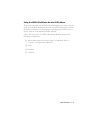
Using BOOTP to Configure the Module and Interfaces . . . . . . . . . . 3-29
BOOTP Description . . . . . . . . . . . . . . . . . . . . . . . . . . . . . . . . . . 3-29
BOOTP Configuration Process . . . . . . . . . . . . . . . . . . . . . . . . . . 3-29
BOOTP Requirements . . . . . . . . . . . . . . . . . . . . . . . . . . . . . . . . 3-30
Using BOOTP . . . . . . . . . . . . . . . . . . . . . . . . . . . . . . . . . . . . . . 3-30
Sample BOOTPtab file . . . . . . . . . . . . . . . . . . . . . . . . . . . . . . . . 3-30
Assigning Interfaces to Networks . . . . . . . . . . . . . . . . . . . . . . . . . . . . . 3-32
Using the DIP Switch to Assign Networks . . . . . . . . . . . . . . . . . . . . 3-33
Using Management Commands to Assign Interfaces to Networks . . 3-35
Management Command Examples . . . . . . . . . . . . . . . . . . . . . . 3-36
Saving Network Assignments . . . . . . . . . . . . . . . . . . . . . . . . . . 3-37
Showing Module and Interface Configurations . . . . . . . . . . . . . . . . . . . 3-37
Show Module Command . . . . . . . . . . . . . . . . . . . . . . . . . . . . . . . . 3-37
Show Port Command . . . . . . . . . . . . . . . . . . . . . . . . . . . . . . . . . . . 3-38
Re-initializing the RMON MultiProbe Module . . . . . . . . . . . . . . . . . . . . 3-40
Warm-Starting the RMON MultiProbe Module . . . . . . . . . . . . . . . . 3-41
Cold-Starting the RMON MultiProbe Module . . . . . . . . . . . . . . . . . 3-42
vi Ethernet RMON MultiProbe Module Installation and Operation Guide
Chapter 4 — Troubleshooting
Troubleshooting Startup Problems . . . . . . . . . . . . . . . . . . . . . . . . . . . . .
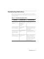
Troubleshooting Malfunctions . . . . . . . . . . . . . . . . . . . . . . . . . . . . . . . .
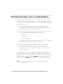
Troubleshooting Network Connectivity Problems . . . . . . . . . . . . . . . . . .
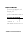
Technical Assistance . . . . . . . . . . . . . . . . . . . . . . . . . . . . . . . . . . . . . . . .
4-2
4-3
4-8
4-9
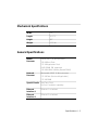
Appendix A — Specifications
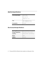
Electrical Specifications . . . . . . . . . . . . . . . . . . . . . . . . . . . . . . . . . . . . . . A-2
Environmental Specifications . . . . . . . . . . . . . . . . . . . . . . . . . . . . . . . . . A-2
Mechanical Specifications . . . . . . . . . . . . . . . . . . . . . . . . . . . . . . . . . . . . A-3
General Specifications . . . . . . . . . . . . . . . . . . . . . . . . . . . . . . . . . . . . . . A-3
Connectors and Cables . . . . . . . . . . . . . . . . . . . . . . . . . . . . . . . . . . . . . A-4
RS-232 25-Pin Port Connector Pinouts . . . . . . . . . . . . . . . . . . . . . . . A-5
RS-232 Crossover Cable for a PC or Terminal . . . . . . . . . . . . . . . . . . A-6
Modem Cable Pinouts . . . . . . . . . . . . . . . . . . . . . . . . . . . . . . . . . . . A-7
Sample Out-of-Band Connections . . . . . . . . . . . . . . . . . . . . . . . . A-7
Using the RMON MultiProbe Module SLIP Address . . . . . . . . . . . A-9
RS-232 Straight-Through Cable . . . . . . . . . . . . . . . . . . . . . . . . A-10
RS-232 Null-Modem Cable . . . . . . . . . . . . . . . . . . . . . . . . . . . . A-11
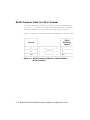
Memory Configuration Allocation . . . . . . . . . . . . . . . . . . . . . . . . . . . . A-12
Appendix B — Technical Support
On-line Technical Support . . . . . . . . . . . . . . . . . . . . . . . . . . . . . . . . . . .
Email Technical Support . . . . . . . . . . . . . . . . . . . . . . . . . . . . . . . . . .
World Wide Web Site . . . . . . . . . . . . . . . . . . . . . . . . . . . . . . . . . . . .
Support from Your Network Supplier . . . . . . . . . . . . . . . . . . . . . . . . . . .
Support from 3Com . . . . . . . . . . . . . . . . . . . . . . . . . . . . . . . . . . . . . . . .
Returning Products for Repair . . . . . . . . . . . . . . . . . . . . . . . . . . . . . . . . .
Accessing the 3Com MIB . . . . . . . . . . . . . . . . . . . . . . . . . . . . . . . . . . . .
3Com Technical Publications . . . . . . . . . . . . . . . . . . . . . . . . . . . . . . . . .
B-1
B-2
B-2
B-2
B-3
B-4
B-4
B-5
Index
Ethernet RMON MultiProbe Module Installation and Operation Guide vii
viii Ethernet RMON MultiProbe Module Installation and Operation Guide
Figures
Figure 1-1.
Figure 2-1.
Figure 2-2.
Figure 2-3.
Figure 3-1.
Figure 3-2.
Figure 3-3.
Figure 3-4.
Figure 3-5.
Figure 3-6.
Figure 3-7.
Figure 3-8.
Figure A-1.
Figure A-2.
Figure A-3.
RMON Sample Application . . . . . . . . . . . . . . . . . . . . . . . 1-9
RMON MultiProbe Module in the
ONline System Concentrator . . . . . . . . . . . . . . . . . . . . . . 2-6
Main Configuration Menu . . . . . . . . . . . . . . . . . . . . . . . 2-9
RMON MultiProbe Module Front Panel LEDs
and Reset Button . . . . . . . . . . . . . . . . . . . . . . . . . . . . . 2-11
Configuration Menu Flow Chart . . . . . . . . . . . . . . . . . . . 3-3
Main Configuration Menu . . . . . . . . . . . . . . . . . . . . . . . 3-7
Download Menu . . . . . . . . . . . . . . . . . . . . . . . . . . . . . . . 3-9
Modify/View Configuration Values Menu . . . . . . . . . . . 3-11
Modify/View Serial Configuration Values Menu . . . . . . . 3-14
Modify/View Network Settings Menu . . . . . . . . . . . . . . 3-21
Modify/View Network Interface 1 Settings Menu . . . . . 3-24
DIP Switch Location . . . . . . . . . . . . . . . . . . . . . . . . . . . 3-33
RS-232 Crossover Cable for a Terminal With a
25-Pin Connector . . . . . . . . . . . . . . . . . . . . . . . . . . . . . . A-6
Out-of-Band Connections to the RMON
MultiProbe Module . . . . . . . . . . . . . . . . . . . . . . . . . . . . . A-8
RS-232 Straight-Through Cable Pinouts . . . . . . . . . . . . A-11
Ethernet RMON MultiProbe Module Installation and Operation Guide ix
x Ethernet RMON MultiProbe Module Installation and Operation Guide
Tables
Table 2-1.
Table 2-2.
Table 3-1.
Table 3-2.
Table 3-3.
Table 3-4.
Table 3-5.
Table 3-6.
Table 3-7.
Table 3-8.
Table 3-9.
Table 3-10.
Table 3-11.
Table 4-1.
Table 4-2.
Table A-1.
Table A-2.
Table A-3.
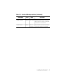
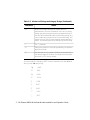
Quick Installation Steps . . . . . . . . . . . . . . . . . . . . . . . . . . 2-3
Module LED Interpretations . . . . . . . . . . . . . . . . . . . . . . 2-12
Main Configuration Menu Description . . . . . . . . . . . . . . . 3-8
Download Menu Description . . . . . . . . . . . . . . . . . . . . . 3-10
Modify/View Configuration Values Menu
Description . . . . . . . . . . . . . . . . . . . . . . . . . . . . . . . . . . 3-12
Modify/View Serial Configuration Values
Menu Description . . . . . . . . . . . . . . . . . . . . . . . . . . . . . 3-15
Modem Init Strings and Hangup Strings . . . . . . . . . . . . . 3-17
Connect Response String Example . . . . . . . . . . . . . . . . . 3-19
Modify/View Network Settings Menu Description. . . . . . 3-22
Modify/View Network Interface Settings Menu
Description . . . . . . . . . . . . . . . . . . . . . . . . . . . . . . . . . . 3-25
Network Selection DIP Switch Settings . . . . . . . . . . . . . . 3-34
RMON MultiProbe Module Information Preserved
and Lost on Warm Start . . . . . . . . . . . . . . . . . . . . . . . . . 3-41
RMON MultiProbe Module Information Preserved
and Lost on Cold Start . . . . . . . . . . . . . . . . . . . . . . . . . . 3-42
Diagnostic Tests and Interface Status LEDs . . . . . . . . . . . . 4-2
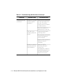
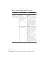
Troubleshooting Malfunctions . . . . . . . . . . . . . . . . . . . . . 4-3
RMON MultiProbe Module RS-232 25-Pin Port
Connector Pinouts . . . . . . . . . . . . . . . . . . . . . . . . . . . . . . A-5
RS-232 Straight-Through Cable Pinouts . . . . . . . . . . . . . A-10
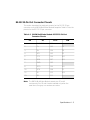
Maximum Number of Entries for Ethernet Tables . . . . . . A-12
Ethernet RMON MultiProbe Module Installation and Operation Guide xi
xii Ethernet RMON MultiProbe Module Installation and Operation Guide
How to Use This Guide
This guide describes how to install the 3Com Ethernet RMON MultiProbe™
Module into the 3Com ONline™ System Concentrator and the ONcore®
Switching Hub. This guide also provides troubleshooting suggestions to use
if a problem occurs with the module.
Audience
This guide is intended for the following people at your site:
❑
Network manager or administrator
❑
Hardware installer
Ethernet RMON MultiProbe Module Installation and Operation Guide xiii
Structure of This Guide
This guide contains the following chapters and appendix:
Chapter 1, Introduction – Provides an introduction to the 3Com Ethernet
RMON MultiProbe Module.
Chapter 2, Installing the Module – Describes the installation
procedures for the module and describes how to monitor the front panel.
Chapter 3, Configuring the Module – Describes how to configure the
module for operation.
Chapter 4, Troubleshooting – Describes troubleshooting information
for correcting possible problems during module installation or operation.
Appendix A, Specifications – Provides specifications for the RMON
MultiProbe Module.
Appendix B, Technical Support – Lists the various methods for
contacting the 3Com technical support organization and for accessing
other product support services.
Index
xiv Ethernet RMON MultiProbe Module Installation and Operation Guide
Document Conventions
The following document conventions are used in this guide:
Convention
Courier text
Indicates
Example
User input
In the Agent Information Form,
enter MIS in the New Contact
field.
System output
After pressing the Apply
button, the system displays
the message
Transmitting data.
Bold command
string
Path names
Before you begin, read the
readme.txt file located in
/usr/snm/agents.
Italic text in braces
User-substituted
identifiers
Use the following command to
show port details:
SHOW PORT {slot.all} VERBOSE
Capitalized text in
plain brackets
Keyboard entry
by the user
Type your password and press
[ENTER].
Italics
Text emphasis,
document titles
Ensure that you press the Apply
button after you add the new
search parameters.
Ethernet RMON MultiProbe Module Installation and Operation Guide xv
Convention
Note:
Indicates
A Note. The
information is
important
Example
Note: Use STP lobe
cables for your system.
Caution: A Caution. A
condition may
damage
software or
hardware
Caution: Do not put
your installation
diskettes on a
magnetic surface.
This may damage the
diskettes.
Warning: A Warning. A
condition may
threaten
personal safety
Warning: Wear eye
protection when
performing these
maintenance
procedures.
Related Documents
This section provides information on suppo rting documentation, including:
❑
3Com Documents
❑
Reference Documents
xvi Ethernet RMON MultiProbe Module Installation and Operation Guide
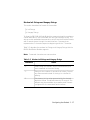
3Com Documents
The following documents provide additional information on 3Com
products:
ONline System Concentrator Installation and Operation Guide - Provides
information on the installation, operation, and configuration of the
ONline System Concentrator. This guide also describes the principal
features of the ONline Fault-Tolerant Controller Module.
ONcore Switching Hub Installation and Operation Guide - Provides
information on the installation, operation, and configuration of the
ONcore Switching Hub. This guide also describes the principal features of
the ONcore Fault-Tolerant Controller Module.
ONline Ethernet Management Module Installation and Operation Guide Provides information on the operation, installation, and configuration of
the ONline Ethernet Management Module.
Distributed Management Module User’s Guide - Provides information on
the operation, installation, and configuration of the ONcore Distributed
Management Module. This guide also describes the software commands
associated with the Distributed Management Module.
ONline Management Commands Guide - Describes the software
commands associated with the ONline Management Modules.
Distributed Management Module Commands Guide - Describes each
management command by providing detailed information on the
commands’s format, use, and description.
For a complete list of 3Com documents, contact your 3Com representative.
Ethernet RMON MultiProbe Module Installation and Operation Guide xvii
Reference Documents
The following documents supply related background information:
Case, J., Fedor, M., Scoffstall, M., and J. Davin, The Simple Network
Management Protocol, RFC 1157, University of Tennessee at Knoxville,
Performance Systems International and the MIT Laboratory for Computer
Science, May 1990.
Rose, M., and K. McCloghrie, Structure and Identification of
Management Information for TCP/IP-based Internets, RFC 1155,
Performance Systems International and Hughes LAN Systems, May 1990.
Waldbusser S., Remote Network Monitoring Management Information
Base, RFC 1757, Carnegie Mellon University, February 1995.
xviii Ethernet RMON MultiProbe Module Installation and Operation Guide
1
Introduction
This chapter provides an introduction to the 3Com Ethernet RMON
MultiProbe Module (hereafter referred to as the RMON MultiProbe
Module). The RMON MultiProbe Module is managed by the following
3Com management modules:
❑
ONcore® Distributed Management Module (Version V2.10)
❑
ONline Ethernet Management Module (Version V4.20)
This chapter contains the following sections:
❑
RMON Overview
❑
RMON MultiProbe Module Overview
❑
RMON MultiProbe Module Features
Introduction 1 - 1
RMON Overview
Remote Monitoring (RMON) is a standards-based network management
tool that allows you to efficiently and effectively monitor segments
throughout the network. You can use RMON to identify and isolate
potential problems in your network before disruptions occur.
RMON-compliant devices operate without impacting network operation.
They function as promiscuous devices, which listen to and capture data on
the network, but do not add additional traffic.
The following sections describe:
❑
RMON Architecture
❑
Ethernet RMON Groups
RMON Architecture
RMON technology requires two components within a network:
❑
RMON Probe
❑
RMON Client
RMON Probe
An RMON probe contains both hardware and software, and is referred to
as the RMON agent. As a promiscuous device, the RMON probe:
❑
Observes packets on the network
❑
Captures packets that match user-defined criteria
❑
Stores packets from the network segment
Through the packet capture and store feature, the RMON agent provides
an extensive set of Ethernet-based statistics to the network manager.
1 - 2 Ethernet RMON MultiProbe Module Installation and Operation Guide
RMON Client
The RMON Client consists of a management station running an application
that uses SNMP (such as the 3Com ONdemand LANsentry™ software) to
request data from the probe and display that data in various formats. You
can also use the graphical interface to configure the RMON agent.
The client application does not have to be located on the same segments as
the network to which the probe is assigned, but does need connectivity to
the networks.
Ethernet RMON Groups
The Ethernet RMON standard is defined in Request For Comment (RFC)
1757 (formerly 1271). The goal of the standard is to ensure interoperability
in multivendor environments. As defined by the RFC standards for Ethernet
RMON, the Ethernet RMON specification identifies the following RMON
groups:
❑
Alarm Group - Allows you to define and set thresholds for various
counters. If a counter reaches a predefined threshold, an event is
generated. (See Event Group below.)
❑
Event Group - Controls the action taken as a result of an event, (an
event can be triggered by an alarm). For example, if a counter
reaches a threshold, then a trap may be generated or an event may
be logged.
❑
Filter Group - Instructs the RMON MultiProbe Module to capture
only those packets that match a specific criteria (such as IP Protocol
or a specific MAC address).
❑
History Group - Provides historical views of statistics based on
predefined sampling intervals. This information illustrates traffic or
error patterns, which can be useful in trend analysis.
❑
Host Group - Contains statistical counters, grouped by MAC address,
specific to each station on the network. This group also contains the
order in which devices or stations were discovered.
Introduction 1 - 3
❑
HostTopN Group - Sorts stations by top traffic contributors. You can
use this information to identify the most active hosts on a segment or
the hosts producing the most errors.
❑
Matrix Group - Collects statistics between pairs of devices on the
network and tracks information specific to each connection, such as
the number of packets transmitted between devices.
❑
Packet Capture Group - Handles the capture and uploading of
packets collected by the RMON MultiProbe Module.
❑
Statistics Group - Contains cumulative traffic and error statistics (for
example, packet distribution, and Cyclic Redundancy Check) for each
device being monitored.
1 - 4 Ethernet RMON MultiProbe Module Installation and Operation Guide
RMON MultiProbe Module Overview
The RMON MultiProbe Module is a single-slot Ethernet module that you
install in an ONline and ONcore hub. The RMON MultiProbe Module can
monitor up to three Ethernet networks simultaneously and perform all
functions on all networks in parallel.
The RMON MultiProbe Module supports:
❑
UDP/IP (User Datagram Protocol/Internet Protocol) over Ethernet
❑
SLIP (Serial Line Internet Protocol)
❑
SNMP (Simple Network Management Protocol) over UDP for
management access
❑
ICMP (Internet Control Message Protocol) Echo and Redirect
Introduction 1 - 5
RMON MultiProbe Module Features
When you use the RMON MultiProbe Module in conjunction with an RMON
client application, you can:
❑
Monitor the network
❑
Generate reports based on network information
❑
Filter and capture packets
❑
Process events and thresholds
❑
Detect network events
In addition, the RMON MultiProbe Module monitors:
❑
Per-network collisions
❑
Per-port collisions (PPC)
❑
Port-address correlation (PAC)
1 - 6 Ethernet RMON MultiProbe Module Installation and Operation Guide
Other benefits of the RMON MultiProbe Module include:
❑
3Com TriChannel™ Architecture - The RMON MultiProbe Module
operates in an ONline System Concentrator and an ONcore Switching
Hub.
❑
Slot Independence - You can install modules into any available slot
in a 3Com ONline or ONcore hub. This flexibility eliminates the need
to shut down the network and rearrange the existing configuration
of the concentrator when you install new modules.
❑
Hot Swap Capability - You can install or remove modules from the
ONline or ONcore hubs when the hub is powered up without
affecting the operation of any other modules in the concentrator.
❑
Management Support - You can manage the RMON MultiProbe
Module through the 3Com® ONdemand LANsentry application. You
can also manage the module using terminal management through an
ONline Ethernet Management Module (EMM) or an ONcore
Distributed Management Module (DMM).
❑
Compliance - The 3Com Ethernet RMON MultiProbe Module
complies with the RMON standard as defined by RFC 1757.
Introduction 1 - 7
Theory of Operation
This section describes the theory of operation for the RMON MultiProbe
Module.
The RMON MultiProbe Module:
❑
Supports simultaneous analysis of three Ethernet channels
❑
Monitors the network proactively
For example, when a network event occurs or a problem becomes
apparent in the network, you use a protocol analyzer to attempt to isolate
and correct the problem. RMON technology also provides you with
protocol analyzer capabilities. However, RMON takes a more proactive
approach to network monitoring by:
❑
Alerting you of network events before they can become a problem
❑
Providing you with information to help isolate problems
You can also configure the RMON MultiProbe Module to check
continuously for specific error conditions and notify you or log the event
when the conditions occur.
1 - 8 Ethernet RMON MultiProbe Module Installation and Operation Guide
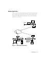
Sample Application
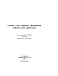
Figure 1-1 illustrates a sample application of RMON MultiProbe Modules in
a concentrator monitoring Ethernet segments in Boston and New York.
With the appropriate interconnections, you can view the RMON data
collected by the RMON MultiProbe Modules from a client workstation
application in Los Angeles
.
RMON
Module
Boston
Router
Router
Router
New York
RMON
Module
Los Angeles
Management
Console with
RMON Client
Application
Figure 1-1. RMON Sample Application
Introduction 1 - 9
2
Installing the Module
This chapter contains the following sections:
❑
Precautionary Procedures
❑
Quick Installation
❑
Unpacking Procedures
❑
Installing the RMON MultiProbe Module
❑
Connecting a Terminal
❑
Initializing the RMON MultiProbe Module
❑
Monitoring the Front Panel
Installing the Module 2 - 1
Precautionary Procedures
Caution: Electrostatic discharge (ESD) can damage
static-sensitive devices on circuit boards.
When you handle the module:
❑
Do not remove the board from its antistatic shielding bag until you
are ready to inspect or install it.
❑
Handle the board by the faceplate only.
Use proper grounding techniques when you install the module, including:
❑
Using a footstrap and grounded mat or wearing a grounded static
discharge wrist strap.
❑
Touching the grounded rack or other source of ground just before
you handle the module.
2 - 2 Ethernet RMON MultiProbe Module Installation and Operation Guide
Quick Installation
Table 2-1 outlines the steps necessary to complete the installation of the
RMON MultiProbe Module. If you are familiar with installing 3Com
modules, use this table as a checklist. Otherwise, consult the remainder of
this chapter.
Table 2-1. Quick Installation Steps
Step
Procedure
Chapter/Section
1
Unpack the module.
Chapter 2, Unpacking
Procedures section
2
Install the module into an open slot in
the hub.
Chapter 2, Installing
the Module section
3
Connect a terminal or management
workstation to the RS-232 console port
on the module faceplate.
Chapter 2,
Connecting a Terminal
section
4
Assign an IP address and subnet mask
for each RMON interface using a
BOOTP server or the configuration
menus.
Chapter 3, Assigning
the Interface IP
Address and Subnet
Mask section
5
Assign a default gateway for the
module using the configuration menus
or BOOTP.
Chapter 3, Assigning
the Module Default
Gateway section
6
Configure the RMON interfaces to a
network using either the DIP switch or
the SET PORT command.
Chapter 3, Assigning
Interfaces to Networks
section.
7
Configure optional module
parameters using the configuration
menus.
Chapter 3, Configuring
the Module
Installing the Module 2 - 3
Unpacking Procedures
To unpack the RMON MultiProbe Module:
1. Verify that the RMON MultiProbe Module (Model Number
RMON-EMP-3) is the model you ordered by checking the model
number listed on the side of the shipping carton.
Note that the product model number printed on the shipping box
differs from the model number on the product. The model number
on the shipping box contains the prefix ‘3C9’.
2. Remove the module, in its antistatic bag, from the shipping carton.
3. Remove the module from the antistatic shielding bag and inspect it
for damage.
Always handle the module by the faceplate, being careful not to
touch the components. If the module appears to be damaged, return
it to the anti-static shielding bag, repack it in the shipping carton, and
contact your local supplier.
Keep the shipping carton and anti-static shielding bag in which your
module was shipped so that you can repackage the module for storage or
shipment.
2 - 4 Ethernet RMON MultiProbe Module Installation and Operation Guide
Installing the RMON MultiProbe Module
You do not need to power down the hub to install or remove the RMON
MultiProbe Module. You can insert the module while the hub is operating
(this is called a hot swap).
To install the RMON MultiProbe Module:
1. Properly ground yourself prior to handling the module.
For example, wear a static wrist guard or touch a grounded static
mat prior to handling the module.
2. Locate an open slot in the hub. Remove a blank panel on the hub to
expose a slot for the module, if necessary.
3. Insert the module into the board guides at the top and bottom of the
slot and slide it into the hub by pressing firmly at the top and bottom
of the faceplate. Make sure the connectors are well-seated into the
backplane of the hub.
Once you install the module, it automatically begins self-diagnostics
and initializes.
Installing the Module 2 - 5
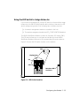
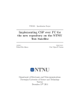
Figure 2-1 shows the RMON MultiProbe Module installed in an
ONline System Concentrator. You can also install the RMON
MultiProbe Module in the ONcore MultiProtocol Switching Hub using
an ONline Module Adapter Kit.
RMON MultiProbe Module
Figure 2-1. RMON MultiProbe Module in the
ONline System Concentrator
4. Using your fingers, tighten the spring-loaded screws on the front of
the module faceplate (do not overtighten). Once you install the
RMON MultiProbe Module, it begins diagnostic testing automatically.
5. Connect one end of an RS-232 cable to the RS-232 port on the front
of the module.
6. Connect the other end of the cable to a terminal (as described in the
next section).
2 - 6 Ethernet RMON MultiProbe Module Installation and Operation Guide
Connecting a Terminal
You can connect a terminal or workstation running a terminal emulation
program to the RMON MultiProbe Module RS-232 port to:
❑
Configure IP address information for the RMON MultiProbe Module
interfaces
❑
Display the RMON MultiProbe Module configuration
To connect a terminal to the RMON MultiProbe Module:
1. Verify that the terminal is configured as follows:
❑
8-bit data
❑
No parity
❑
1 stop bit
❑
9600 baud rate
Note: The RMON MultiProbe Module does not support XON and
XOFF.
2. Using an RS-232 null-modem cable, attach a terminal (or a
workstation running ASCII terminal emulation software) to the
RMON MultiProbe Module RS-232 port.
Installing the Module 2 - 7
Initializing the RMON MultiProbe Module
Once you complete module installation procedures and attach an RS-232
cable to the front panel, you can initialize the RMON MultiProbe Module
and display the configuration menus.
To initialize the RMON MultiProbe Module and display the configuration
menus:
1. Press the front panel Reset button. Pressing the Reset button
warm-starts the module. (Refer to Chapter 3, Configuring the
Module, for a description of warm and cold starts.)
When reset, the module completes diagnostics and initializes.
2. To display the RMON MultiProbe Module Main configuration menu,
hold down the X key on the terminal keyboard within 15 seconds of
powering up or resetting the module. If you do not hold down the X
key within 15 seconds, the RMON MultiProbe Module:
a. Begins monitoring the network
b. Reports any error messages if the module experiences an error
condition
3. If you miss the 15-second window, press the Reset button to
re-initialize the module.
4. When you hold down the X key, the following banner is displayed:
Tests interrupted!
Boot System Version x.xx for Ethernet RMON
MultiProbe, Rev x
Built on Thu April x, 17:36:58 EST 199x
Loading configuration system.
Entering configuration system. Please
wait.....
2 - 8 Ethernet RMON MultiProbe Module Installation and Operation Guide
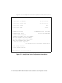
The Main configuration menu appears (Figure 2-2).
Main menu Rev x.xx (Rev x.x)
1 Modify/View configuration values ->
2 Download new firmware ->
3 Warm start and Exit
4 Cold start and Exit
Enter one of: 1 2 3 4 ?
Figure 2-2. Main Configuration Menu
5. Refer to Chapter 3, Configuring the Module, for a description of the
configuration menus and instructions for configuring the module and
its interfaces using the configuration menus.
Once you configure the RMON MultiProbe Module and it initializes
successfully, the module begins to operate normally and monitor the
network.
Note: Hardware flow control is not active on the RMON
MultiProbe Module when you are using the configuration
menus. Depending on the Serial Port Mode setting,
hardware flow control is active when you exit the
configuration menus.
For information on the Serial Port Mode settings, refer to Chapter
3, Configuring the Module, Table 3-4 Modify/View Serial
Configuration Values Menu Description.
Installing the Module 2 - 9
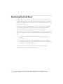
Monitoring the Front Panel
Use the LEDs on the front panel of the RMON MultiProbe Module to
monitor the status of the module and the module interfaces. The RMON
MultiProbe Module front panel also contains a recessed Reset button for
resetting the module.
Resetting the module is equivalent to a warm start. Refer to Chapter 3,
Configuring the Module, the section titled Re-Initializing the RMON
MultiProbe Module for information on warm and cold starts.
When you install the RMON MultiProbe Module in the hub, an Interface
Status LED illuminates for each interface after the following conditions are
met:
❑
The RMON MultiProbe Module completes self-diagnostics and
initializes.
❑
You assign an interface to a network (the interface is enabled
automatically once you assign a network using a 3Com management
module or set the DIP switches).
The Module Status LED illuminates once the module completes
self-diagnostics and initializes (45 seconds).
2 - 10 Ethernet RMON MultiProbe Module Installation and Operation Guide
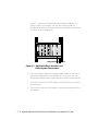
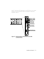
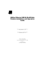
Figure 2-3 shows the LEDs, Reset button, and RS-232 port on the module
faceplate. Each LED indicates the state of the module or interface as
described in Table 2-2.
Interface 1 LEDs
Interface 2 LEDs
Interface 3 LEDs
Status LEDs
Collision LEDs
Activity LEDs
Module Status
Module Reset
Serial Activity
RS-232/SLIP Port
25-Pin Connector
Figure 2-3. RMON MultiProbe Module Front Panel LEDs
and Reset Button
Installing the Module 2 - 11
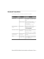
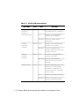
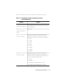
Table 2-2. Module LED Interpretations
LED Name
Color
Interface1
Interface 2
Interface 3
(Interface Status)
Green
Collision
(Interface
Collision)
Yellow
Activity
(Interface
Activity)
Yellow
Module Status
Green
State
Indicates
Off
Interface is set to isolated
(not assigned to any network).
On
Interface is configured to a
network and is enabled.
Blinking
LED blinks briefly during
diagnostics.
Off
Interface is not experiencing
collisions or is isolated.
Blinking
Interface is experiencing
collisions. Blinks once for each
collision detected.
Off
No traffic is being passed or
interface is isolated.
Blinking
Monitors received traffic.
Blinks once for each packet
received.
Off
Module failed diagnostics. This
indicates an unrecoverable
hardware or software error.
Contact the 3Com Customer
Service Center.
On
Module is operating correctly.
Blinking
Blinks at 1-second intervals
during module initialization.
2 - 12 Ethernet RMON MultiProbe Module Installation and Operation Guide
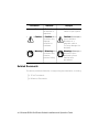
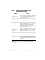
Table 2-2. Module LED Interpretations (Continued)
LED Name
Color
State
Indicates
Serial Activity
Yellow
Blinking
Activity over the RS-232 port.
Blinks once for each character
received or transmitted.
Reset Button
Black
When
pressed
Re-initializes module software
and resets module hardware.
Installing the Module 2 - 13
3
Configuring the
Module
This chapter describes how to configure the 3Com Ethernet RMON
MultiProbe Module for operation.
This chapter contains the following sections:
❑
Configuration Menu Overview
❑
Configuring the Module and Interfaces
❑
Assigning Interfaces to Networks
❑
Showing Module and Interface Configurations
❑
Re-initializing the RMON MultiProbe Module
Configuring the Module 3 - 1
Configuration Menu Overview
This section describes the RMON MultiProbe Module configuration menus
and how to use the menus to configure the module and interface. The
configuration menus enable you to configure the module and interfaces
using a terminal attached to the front panel RS-232 port and an RS-232
null-modem cable. (Refer to Appendix A, Specifications, for information on
cable pinouts.)
This section includes:
❑
Modifying Configuration Menu Values
❑
Using the Main Configuration Menu
❑
Using the Download Menu
❑
Using the Modify/View Configuration Values Menu
❑
Using the Modify/View Serial Configuration Values Menu
❑
Using the Modify/View Network Settings Menu
❑
Using the Modify/View Network Interface Settings Menu
3 - 2 Ethernet RMON MultiProbe Module Installation and Operation Guide
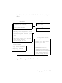
Figure 3-1 is a flow chart of the RMON MultiProbe Module configuration
menus.
Main Menu
1
2
3
4
1
2
3
4
5
6
S
0
Modify/View configuration values
Download new firmware
Warm start and Exit
Cold start and Exit
Enter one of: 1 2 3 4 ?
1 Modify/View Configuration Values
Modify/View network settings
Autodiscovery echo interval (secs)
Date
Time
Timezone
Modify/View serial port settings
Save changes and exit
Cancel changes and exit
3
Warm-start the module
and exit menus
4
Cold-start the module
and exit menus
6 Modify/View Serial
Configuration Values
1 Serial port IP address
2 Serial port subnet mask
3 Serial port speed
1
2
3
4
0
2 Download Menu
Filename to download
tftp server IP address
Download to firmware
Temporary download
Return to previous menu
4 Serial port mode
5 Modem Init String
6 Modem Hangup String
7 Modem Connect Responses
8 Modem No-Connect Responses
S Save changes and exit
0 Cancel changes and exit
Modify/View network settings menu shown on next page
Figure 3-1. Configuration Menu Flow Chart
Configuring the Module 3 - 3
1 Modify/View Network Settings Menu
1
2
3
4
5
Modify/View settings for network interface 1
Modify/View settings for network interface 2
Modify/View settings for network interface 3
Default gateway IP address
BOOTP network interface
Enter one of: 1 2 3 4 5 ?
1,2,and 3 Modify/View network interface x settings
MAC address 08 11 22 33 44 55
1 IP address
2 Subnet mask
S Save changes and exit
0 Cancel changes and exit
Enter one of: 1 2 S 0?
Figure 3-1. Configuration Menu Flow Chart (Continued)
The following sections provide examples of each configuration menu. Each
section also contains a table describing the menu options.
3 - 4 Ethernet RMON MultiProbe Module Installation and Operation Guide
Modifying Configuration Menu Values
The configuration menus contain options that enable you to:
❑
Display additional configuration menus
❑
Display and modify configuration values
To display a menu from within a menu, type the number of the option and
press Return.
To display or modify a value from a configuration menu:
1. Type the number of the option you want to display or modify and
press Return. The configuration menus have a timeout value of 2
minutes. Therefore, you must enter a keystroke to a menu within 2
minutes or the following message displays and the module
automatically warm-starts.
Keyboard input timeout.
Module warm started and config system exited.
2. To modify configuration menu values, delete one character at a time
using the Backspace key. To delete the entire value, press Ctrl-U.
When you press Ctrl-U, <CANCEL> appears at the end of the current
value to verify that the current value is canceled.
3. Enter the new value and press Return.
4. Select S to save changes and exit the current menu, or 0 (zero) to
cancel changes and exit the current menu. Exiting a current menu
brings you up one menu level. When you return to the Main menu,
you must select either a warm or cold start to re-initialize the RMON
MultiProbe Module.
5. To re-initialize the RMON MultiProbe Module, select option 3 for a
warm start or select option 4 for cold start.
(Refer to the section Re-initializing the RMON MultiProbe Module
later in this chapter for information on the effects of warm and cold
starts.)
Configuring the Module 3 - 5
Using the Main Configuration Menu
Use the Main configuration menu to:
❑
Display the Modify/View Configuration Values menu
❑
Download new firmware
❑
Initiate a warm or cold start
To display the Main configuration menu:
1. Press the front panel Reset button to re-initialize the module.
2. Hold down the X key within 15 seconds of powering up or resetting
the module.
3. If you miss the 15-second window, press the Reset button to
re-initialize (warm start) the module.
4. When you hold down the X key, diagnostics are terminated and the
following banner is displayed:
Tests interrupted!
Boot System Version x.xx for Ethernet RMON
MultiProbe, Rev x
Built on Thu April x, 17:36:58 EST 199x
Loading configuration system.
Entering configuration system. Please
wait.....
3 - 6 Ethernet RMON MultiProbe Module Installation and Operation Guide
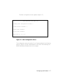
The Main configuration menu appears (Figure 3-2).
Main menu Rev x.xx (Rev x.x)
1 Modify/View configuration values ->
2 Download new firmware ->
3 Warm start and Exit
4 Cold start and Exit
Enter one of: 1 2 3 4 ?
Figure 3-2. Main Configuration Menu
The configuration menus for options 1 and 2 are described in the following
sections. Options 3 and 4 are described in the section Re-initializing the
RMON MultiProbe Module later in this chapter.
Configuring the Module 3 - 7
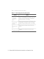
Table 3-1 describes the Main menu options.
Table 3-1. Main Configuration Menu Description
Option
1.
Modify/View
configuration
menu
2.
Download new
firmware
3.
Warm start and
Exit
4.
Cold start and Exit
Result
Displays the Modify/View Configuration Value
menu. For a description of this menu, refer to the
section Using the Modify/View Configuration
Value Menu later in this chapter.
Downloads new firmware to FLASH memory. For
a description of this menu, refer to the section
Using the Download Menu later in this chapter.
Warm-starts the module and exits the menu
system.
Cold-starts the module and exits the menu
system.
3 - 8 Ethernet RMON MultiProbe Module Installation and Operation Guide
Using the Download Menu
Use the Download menu to:
❑
Configure the RMON MultiProbe Module for a software download
❑
Display the current IP address and subnet mask for each interface
To display the Download menu, select option 2 from the Main
configuration menu.
Figure 3-3 is an example of the Download menu.
.
Download Menu Rev x.xx
1 Filename to download ->
/chome/spe/onown/rmon_mod/mar06/ax3_field.rom.cf.1.20
2 tftp server IP address ->
151.104.3.6
3 Download to firmware ->
4 Temporary download
0 Return to previous menu
IP address 1:
Subnet mask 1:
IP address 2:
Subnet mask 2:
IP address 3:
Subnet mask 3:
Default gateway IP address:
151.104.6.7
255.255.255.0
151.104.7.8
255.255.255.0
151.104.8.9
255.255.255.0
151.104.6.1
Enter one of: 1 2 3 4 0 ?
Figure 3-3. Download Menu
Configuring the Module 3 - 9
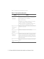
Table 3-2 describes the Download menu options.
Table 3-2. Download Menu Description
Option
1.
Filename to
download
Result
Displays the pathname of the file to download and
enables you to enter a new value. The filename can
be a maximum of 127 characters.
If the download file:
❑ Resides in the /tftpboot directory of the server,
you only need to enter the filename.
❑ Does not reside in the /tftpboot directory, you
must entire the complete directory path.
2.
TFTP Server IP
address
3.
Displays the TFTP server IP address and enables you
to enter a new value.
Initiates a download to FLASH memory.
Download to
firmware
4.
Temporary
download
0.
Return to previous
menu
Initiates a download to RAM. This option enables
you to run and verify the new software before you
initiate a download to FLASH memory. After being
reset, the module reverts to the software contained
in FLASH memory.
Closes the current menu and returns to the Main
menu.
3 - 10 Ethernet RMON MultiProbe Module Installation and Operation Guide
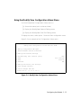
Using the Modify/View Configuration Values Menu
Use the Modify/View Configuration Values menu to:
❑
Set module values (such as date and time)
❑
Display the Modify/View Network Settings menu
❑
Display the Modify/View Serial Port Settings menu
To display this menu, select option 1 from the Main configuration menu.
Figure 3-4 is an example of the Configuration Values menu.
Modify/view configuration values menu Rev N.NN
Memory configuration 8M bytes
Three ethernet network interfaces
1 Modify/View network settings
2 Autodiscovery echo interval (secs)
3 Date
4 Time
1800
Sat 1/28/1995
22:45:05
5 Timezone
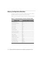
PST
6 Modify/View serial port settings
S Save changes and exit
0 Cancel changes and exit
Enter one of: 1 2 3 4 5 6 S 0 ?
Figure 3-4. Modify/View Configuration Values Menu
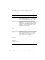
Configuring the Module 3 - 11
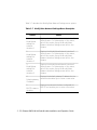
Table 3-3 describes the Configuration Values menu options.
Table 3-3. Modify/View Configuration Values Menu
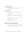
Description
Option
1.
Modify/View
network settings
2.
Autodiscovery
Echo Interval
3.
Date
4.
Time
5.
Timezone
6.
Modify/View
Serial Port settings
Result
Displays the Modify/View Network Settings menu.
For a description of this menu, refer to the section
Using the Modify/View Network Settings menu.
Displays the Autodiscovery Echo Interval and
enables you to enter a new interval (in seconds)
after which the RMON MultiProbe Module sends
an Internet Control Message Protocol (ICMP) echo
request to the default gateway.
Displays the date and enables you to enter a new
value. Use the format: mm/dd/yyyy. Changes are
saved immediately and cannot be canceled. To
correct an error, re-enter the date.
Displays the time and enables you to enter a new
value. Use the format hh:mm:ss. Changes are
saved immediately and cannot be canceled. To
correct an error, re-enter the time.
Displays the time zone and enables you to enter a
new value (for example, EST, GMT).
Displays the Serial Port Configuration menu
containing the current serial port settings. For a
description of this menu, refer to the section Using
the Serial Port Configuration menu later in this
chapter.
3 - 12 Ethernet RMON MultiProbe Module Installation and Operation Guide
Table 3-3. Modify/View Configuration Values Menu
Description (Continued)
Option
S
Save Changes and
Exit
0
Cancel Changes
and Exit
Result
Saves all changes to the configuration menu to
non-volatile memory and returns to the Main
menu.
Cancels changes to the configuration menu and
returns to the Main menu.
Note: All configuration settings except for the Autodiscovery
Echo Interval field value are preserved after a cold start.
Using the Modify/View Serial Configuration Values Menu
Use the Modify/View Serial Configuration Values menu to configure the
module RS-232 serial port to run Serial IP (SLIP):
❑
Over a direct link
❑
Using a modem
The Serial IP feature enables the RMON MultiProbe Module and a network
management workstation to communicate when a network link is not
available.
To display this menu, select option 6 from the Modify/View Configuration
Values Menu and press Return. The Serial Configuration Values menu is
displayed with factory-default settings for the serial port (Figure 3-5).
Configuring the Module 3 - 13
Figure 3-5 is an example of the Serial Configuration Values menu options.
Modify/view serial configuration values menu Rev N.NN
1 Serial port IP address
187.187.187.193
2 Serial port subnet mask
255.255.255.192
3 Serial port speed
4 Serial port mode
5 Modem Init String
6 Modem Hangup String
9600
Direct
^s^MATEOQ0V1X4 S0=1 S2=43^M^d2
^d2^s+++^d2^s^ATH0^M^d2
7 Modem Connect Responses
/CONNECT/300/CONNECT 1200/1200/CONNECT
2400/2400/CONNECT 4800/4800/CONNECT
9600/9600/CONNECT 14400/14400/CONNECT
19200/19200/CONNECT 38400/38400/
8 Modem No-Connect Responses
/NO CARRIER/BUSY/NO DIALTONE/NO ANSWER/ERROR/
S Save changes and exit
0 Cancel changes and exit
Enter one of: 1 2 3 4 5 6 7 8 S O ?
Figure 3-5. Modify/View Serial Configuration Values Menu
3 - 14 Ethernet RMON MultiProbe Module Installation and Operation Guide
Table 3-4 describes the Serial Configuration Values menu options.
Table 3-4. Modify/View Serial Configuration Values
Menu Description
Option
Result
Serial Port IP Address
Displays the serial IP address of the RMON
MultiProbe Module and enables you to enter a
new IP address.
2
Not used.
1
Serial Port Subnet
Mask
3
Serial Port Speed
Displays the serial port speed that sets the
baud rate used by the serial interface and
enables you to enter a new value. Valid values:
1 = 300
2 = 1200
3 = 2400
4 = 4800
5 = 9600
6 = 14400
7 = 19200
8 = 38400
4
Serial Port Mode
Display the serial connection value which
indicates whether or not the connection is
direct or is using a modem and enables you to
enter a new value. Valid values:
1 = direct
2 = modem
3 = direct with hardware flow control
4 = modem with hardware flow control
Configuring the Module 3 - 15
Table 3-4. Modify/View Serial Configuration Values
Menu Description (Continued)
Option
5
Modem Init String
6
Modem Hangup
String
7
Modem Connect
Response
8
Modem No Connect
Response
S
Save Changes and
Exit
0
Cancel Changes and
Exit
Result
Display the modem init string and enables you
to enter a new value. In modem mode, this
string initializes the modem.
Displays the modem hangup string and enables
you to enter a new value. In modem mode, this
string hangs up the modem.
Displays the modem connect response and
enables you to enter a new value. In modem
mode, this string contains valid modem
connect responses and the baud rate to which
the serial port should be set.
Displays the modem no connect response and
enables you to enter a new value. In modem
mode, this string lists the modem connection
failure response codes.
Saves changes to the serial port configuration
menu to non-volatile memory and returns to
the Modify/View Configuration Values menu.
Cancels changes to the configuration menu
and returns to the Modify/View Configuration
Values menu.
Note: All serial configuration information is preserved after a cold
start.
3 - 16 Ethernet RMON MultiProbe Module Installation and Operation Guide
Modem Init Strings and Hangup Strings
This section describes the format of the modem:
❑
Init Strings
❑
Hangup Strings
To allow the RMON MultiProbe Module to communicate with a modem or
a serial data switch, use the modem Init String and Hangup String. The
strings contain embedded commands to control how the module interacts
with a remote device through the serial interface. Commands are
represented as 2-character sequences beginning with the ^ character.
Table 3-5 describes the modem Init Strings and Hangup Strings that the
RMON MultiProbe Module supports.
Note: Command characters are case-sensitive.
Table 3-5. Modem Init Strings and Hangup Strings
Command
Result
^s
Sends string that follows, which is terminated by the
next command or the end of string.
^c
Delays for the number of seconds that follows. Discard
any data received instead of storing it in a buffer for
parsing.
^t
Sets timeout to the value represented by the decimal
digits that follow. The default timeout is 20 seconds. The
timeout may be overridden by a smaller serial Timeout
configured for the associated serial interface.
Configuring the Module 3 - 17
Table 3-5. Modem Init Strings and Hangup Strings (Continued)
Command
Result
^w
Waits for the reply string that follows which is
terminated by the next command or the end of string.
Partial and case insensitive matching is applied (that is, if
the RMON MultiProbe Module finds the reply string [any
case combination] anywhere in the received string, the
match is found). If the current timeout elapses without a
match, the module ignores the remaining control string.
^!
The ^ character.
^d
Delays the number of seconds specified by the decimal
digits that follow.
^b
Sends break for the number of milliseconds specified by
the decimal digits that follow. If no digits follow, break is
enforced for 250 ms by default.
You may insert the following ASCII control characters into the ^s send
string or the ^w reply string:
^@
0x00
^A
0x01
^M
0x0D
^Z
0x1A
^[
0x1B
^\
0x1C
^]
0x1D
^^
0x1E
^_
0x1F
3 - 18 Ethernet RMON MultiProbe Module Installation and Operation Guide
You may also insert binary data into the data stream using the following
control sequence for each byte of binary data: ^0x## (where ## is the
hexadecimal representation of the data byte).
Two ASCII characters (0-9, a-f, A-F) must follow the ^0x control prefix. For
example, ^0x0D^0x0A is interpreted as a carriage return followed by a line
feed.
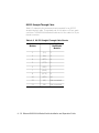
Modem Response Strings
This section describes the modem response string formats:
❑
Connect Response Strings
❑
No Connect Response Strings
Connect Response - An ASCII string that contains substrings that describe
the expected modem connection response code and associated bps rate.
The substrings are delimited by the first character in the string.
The following connect response string example is interpreted in Table 3-6.
CONNECT/300/CONNECT 1200/1200/CONNECT
2400/2400/CONNECT 4800/4800/CONNECT 9600/9600
Table 3-6. Connect Response String Example
Response code
Bps rate
CONNECT
300
CONNECT1200
1200
CONNECT 2400
2400
CONNECT 4800
4800
CONNECT 9600
9600
Configuring the Module 3 - 19
The RMON MultiProbe Module uses the information in this string to adjust
the bps rate of the serial interface once you establish a modem connection.
No Connect Response - An ASCII string that contains response codes
generated by a modem to report the reason for a connection attempt
failure. The response codes are delimited by the first character in the string.
For example:
/NO CARRIER /BUSY/NO DIALTONE/NO ANSWER/ERROR/
If the RMON MultiProbe Module receives one of the response codes on its
serial interface while attempting to makea modem con nection, the module
issues the hangup command as specified by modem Hangup String.
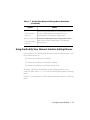
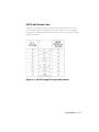
Using the Modify/View Network Settings Menu
Use the Modify/View Network Settings menu to:
❑
Display the Modify/View Network Interface Settings menu for each
interface
❑
Display and modify the module default gateway
❑
Display and modify the BOOTP network interface
To display this menu, select option 1 from the Modify/View Configuration
Values menu.
3 - 20 Ethernet RMON MultiProbe Module Installation and Operation Guide
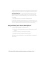
Figure 3-6 is an example of the Modify/View Network Settings menu.
Modify/View Network Settings Menu
1 Modify/View settings for network interface 1
2 Modify/View settings for network interface 2
3 Modify/View settings for network interface 3
4 Default gateway IP address
151.104.3.6
5 BOOTP network interface
1
S Save changes and exit
0 Cancel changes and exit
Enter one of: 1 2 3 4 5 S 0?
Figure 3-6. Modify/View Network Settings Menu
Configuring the Module 3 - 21
Table 3-7 describes the Modify/View Network Settings menu options.
Table 3-7. Modify/View Network Settings Menu Description
Option
1
Modify/View
settings for
network
interface 1
2
Modify/View
settings for
network
interface 2
3
Modify/View
settings for
network
interface 3
4
Default gateway
IP address
5
BOOTP network
interface
Result
Displays the Modify/View Network Interface 1
Settings menu. For a description of this menu,
refer to the section Using the Modify/View
Network Interface Settings menu later in this
chapter.
Displays the Modify/View Network Interface 2
Settings menu. For a description of this menu,
refer to the section Using the Modify/View
Network Interface Settings menu later in this
chapter.
Displays the Modify/View Network Interface 3
Settings menu. For a description of this menu,
refer to the section Using the Modify/View
Network Interface Settings menu later in this
chapter.
Displays the default gateway IP address for the
module and enables you to enter a new value.
Displays the network interface configured for
BOOTP and enables you to enter a new value.
3 - 22 Ethernet RMON MultiProbe Module Installation and Operation Guide
Table 3-7. Modify/View Network Settings Menu Description
(Continued)
Option
S
Save Changes
and Exit
0
Cancel Changes
and Exit
Result
Saves all changes made to the configuration menu
to non-volatile memory and returns to the
Modify/View Configuration Values menu.
Cancels changes made to the Configuration menu
and returns to the Modify/View Configuration
Values menu.
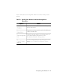
Using the Modify/View Network Interface Settings Menus
Each interface has a Modify/View Network Interface Settings menu. Use
the interface menus to:
❑
Display the module MAC address
❑
Display and modify the interface IP address
❑
Display and modify the interface subnet mask
To display a Modify/View Network Interface Settings menu for an
interface, select option 1, 2, or 3 from the Modify/View Network Settings
menu.
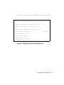
Figure 3-7 is an example of the Modify/View Network Interface 1 Settings
menu
Configuring the Module 3 - 23
.
Modify/View Network Interface 1 Settings Menu
MAC address 08 11 22 33 44 55
1 IP address
2 Subnet mask
151.104.6.7
255.255.255.0
S Save changes and exit
0 Cancel changes and exit
Enter one of: 1 2 S 0?
Figure 3-7. Modify/View Network Interface 1 Settings Menu
3 - 24 Ethernet RMON MultiProbe Module Installation and Operation Guide
Table 3-8 describes the Modify/View Network Interface Settings menu
options.
Table 3-8. Modify/View Network Interface Settings Menu
Description
Option
1
IP address
2
Subnet Mask
S
Save Changes and
Exit
0
Cancel Changes
and Exit
Result
Displays the interface IP addressand enables you to
enter a new value.
Displays the interface subnet mask and enables you
to enter a new value.
Saves all changes made to the Interface menu to
non-volatile memory and returns to the
Modify/View Network Settings menu.
Cancels changes made to the Interface menu and
returns to the Modify/View Network Settings
menu.
Configuring the Module 3 - 25
Configuring the Module and Interfaces
Before the RMON MultiProbe Module can become operational, you must
configure the following parameters for the module and interfaces:
❑
IP address (for each interface)
❑
Subnet mask (for each interface)
❑
Default gateway (for the module)
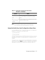
Assigning the Interface IP Address and Subnet Mask
You must assign a unique IP network address for each interface.
For example, if you do not bridge the three interfaces, you could assign IP
addresses for a subnetted class B network as shown in the following IP
address examples:
Note: In both of the IP address examples, each interface has a
subnet mask of 255.255.255.0.
❑
Interface 1 - 151.104.36.7
❑
Interface 2 - 151.104.37.8
❑
Interface 3 - 151.104.38.9
For example, if you bridge the three interfaces, the network portion of the
IP addresses can be identical as shown in the following IP address
examples:
❑
Interface 1 - 151.104.36.7
❑
Interface 2 - 151.104.36.8
❑
Interface 3 - 151.104.36.9
3 - 26 Ethernet RMON MultiProbe Module Installation and Operation Guide
This configuration sets up one interface for each bridged segment.
To assign an IP address or subnet mask for an interface:
1. From the Main menu, select option 1, Modify/View Configuration
Values, and press Return. The Modify/View Configuration Values
menu is displayed (see Figure 3-4).
2. From the Modify/View Configuration Values menu, select option 1,
Modify/View Network Settings, and press Return. The Modify/View
Network Settings menu is displayed (see Figure 3-6).
3. From the Modify/View Network Settings menu, select option 1, 2, or
3 (depending on which interface you want to modify) and press
Return. The Modify/View Network Interface 1 Settings menu is
displayed (Figure 3-7).
4. To assign:
a. An IP address, select option 1. The module displays the current
value and prompts you to enter a new value.
b. A subnet mask, select option 2. The module displays the current
value and prompts you to enter a new value.
5. To modify an IP address or subnet mask, delete one character at a
time using the Backspace key. To delete the entire value, press Ctrl-U.
6. Enter the new value and press Return.
7. Select S to save the changes and return to the previous menu.
8. Repeat steps 3 through 7 to assign an IP address and subnet mask
for each interface.
Configuring the Module 3 - 27
Assigning the Module Default Gateway
You must assign a default gateway for the RMON MultiProbe Module.
To assign a default gateway:
1. From the Main menu, select option 1, Modify/View Configuration
Values, and press Return. The Modify/View Configuration Values
menu is displayed (see Figure 3-4).
2. From the Modify/View Configuration Values menu, select option 1,
Modify/View Network Settings, and press Return. The Modify/View
Network Settings menu is displayed (see Figure 3-6).
3. From the Modify/View Network Settings menu, select option 4 and
press Return. The module displays the current default gateway and
prompts you to enter a new value.
4. Enter the new default gateway.
5. To save the changes and return to the previous menu, select S.
3 - 28 Ethernet RMON MultiProbe Module Installation and Operation Guide
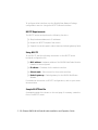
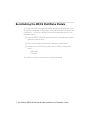
Using BOOTP to Configure the Module and Interfaces
This section describes:
❑
BOOTP Description
❑
BOOTP Configuration Process
❑
BOOTP Requirements
❑
Using BOOTP
BOOTP Description
BOOTP (Bootstrap Protocol) is a UDP/IP-based (User Datagram
Protocol/Internet Protocol) broadcast protocol which allows a device to
configure itself dynamically without user intervention. Use BOOTP to
download configuration information from a BOOTP server to the RMON
MultiProbe Module interface configured for BOOTP.
BOOTP Configuration Process
During initialization, the RMON MultiProbe Module verifies that the IP
address and subnet mask of the interface configured for BOOTP is not set
to null (all zeros). If either the IP address or subnet mask are null, the
module automatically sends out BOOTP requests every 60 seconds through
the designated BOOTP interface until it receives a valid BOOTP response. If
the default gateway is originally set to null, the BOOTP server also supplies
the module with gateway information.
The response from the BOOTP server supplies the RMON MultiProbe
Module with its network parameters. When BOOTP obtains valid addresses,
the module stores the parameters in battery-backed RAM and becomes
operational.
The RMON MultiProbe Module defaults to interface 1 for a BOOTP server.
Because only one interface at a time can be used with BOOTP, you can only
download configuration information to the interface configured for BOOTP.
Configuring the Module 3 - 29
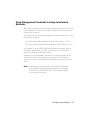
To configure other interfaces, use the Modify/View Network Settings
configuration menu to change the BOOTP network interface.
BOOTP Requirements
The BOOTP server must perform the following functions:
❑
Map hardware addresses to IP addresses
❑
Respond to BOOTP requests from clients
❑
Support the vendor-specific subnet mask and default gateway fields
Using BOOTP
To use BOOTP, add the following information to the BOOTP server
bootptab configuration file:
❑
MAC address - Hardware address of the RMON MultiProbe Module
interface to be configured
❑
IP address - IP address for the module interface
❑
Subnet mask - Subnet mask for the module interface
❑
Default gateway - Default gateway for the RMON MultiProbe
Module
For additional information on BOOTP configurations, refer to your server
documentation.
Sample BOOTPtab file
A sample bootptab file is shown on the next page. If necessary, create this
file on the BOOTP server.
3 - 30 Ethernet RMON MultiProbe Module Installation and Operation Guide
# /etc/bootptab: database for bootp server (/etc/bootpd)
# Blank lines and lines beginning with '#' are ignored.
#
# Legend:
#
#
first field -- hostname
#
(should be full domain name)
#
#
hd -- home directory
#
bf -- bootfile
#
cs -- cookie servers
#
ds -- domain name servers
#
gw -- gateways
#
ha -- hardware address
#
ht -- hardware type
#
im -- impress servers
#
ip -- host IP address
#
lg -- log servers
#
lp -- LPR servers
#
ns -- IEN-116 name servers
#
rl -- resource location protocol servers
#
sm -- subnet mask
#
tc -- template host (points to similar host entry)
#
to -- time offset (seconds)
#
ts -- time servers
# Define a global entry which specifies the information every host uses.
#
global.dummy:\
:hd=/tftpboot:bf=null
# Define different master entries for each subnet. . .
default:vm=rfc1048:hd=/tftpboot:bf="null":sm=255.255.255.0:
js-test-64:ip=151.104.15.2:\
ht=ethernet:\
ha=081122334455:\
gw=151.104.15.1:\
tc=default
Configuring the Module 3 - 31
Assigning Interfaces to Networks
To assign RMON MultiProbe Module interfaces to networks, you can use
either:
❑
DIP switch settings, if your hub is unmanaged (an ONline or ONcore
management module is not installed in the hub).
❑
ONline or ONcore network management commands (if an ONline or
ONcore management module is installed in the hub).
You can assign the three RMON MultiProbe Module network interfaces as
follows:
❑
Interface 1 to Ethernet 1 or Isolated
❑
Interface 2 to Ethernet 2 or Isolated
❑
Interface 3 to Ethernet 3 or Isolated
Note: Each interface can only be configured to its corresponding
Ethernet network or isolated (that is, Interface 1 to
Ethernet 1, Interface 2 to Ethernet 2, Interface 3 to
Ethernet 3).
3 - 32 Ethernet RMON MultiProbe Module Installation and Operation Guide
Using the DIP Switch to Assign Networks
If you have an unmanaged hub, use the DIP switch on the module to assign
networks to the RMON MultiProbe Module interfaces. However, the DIP
switch settings are ignored if the following two conditions are met:
❑
A network management module is installed in the hub.
❑
The master management module has DIP_CONFIGURATION disabled.
The RMON MultiProbe Module contains an 8-position DIP switch (SW1).
This DIP switch allows you to configure and enable the three RMON
MultiProbe Module interfaces to the corresponding Ethernet networks.
Figure 3-8 shows the DIP switch location on the module
.
SW1
Dip Switches
On
1 1 2 3 4 5 6 78
NOT USED
NOT USED
CH1EN
CH2EN
CH3EN
NOT USED
NOT USED
NOT USED
Off
0
Backplane DIN
Connector
Figure 3-8. DIP Switch Location
Configuring the Module 3 - 33
Table 3-9 describes the positions of the DIP switches required to configure
and enable the RMON MultiProbe Module interfaces to corresponding
Ethernet networks. As the table shows, switches 1, 2, 6, 7, and 8 are not
used.
Table 3-9. Network Selection DIP Switch Settings
Switch
Setting
Network Selection
ON
OFF
1
Reserved
2
Reserved
3
Ethernet 1
Isolated
4
Ethernet 2
Isolated
5
Ethernet 3
Isolated
6
Reserved
7
Reserved
8
Reserved
3 - 34 Ethernet RMON MultiProbe Module Installation and Operation Guide
Using Management Commands to Assign Interfaces to
Networks
With a terminal attached to a 3Com management module console, you can
use management commands to assign the RMON MultiProbe Module
interfaces to networks.
The following 3Com network management modules enable you to assign
interfaces to networks:
❑
ONline Ethernet Management Module (EMM) (Version V4.20)
❑
ONcore Distributed Management Module (DMM) (Version V2.10)
To configure all other RMON MultiProbe Module parameters (such as
IP address, subnet mask, and serial configurations), use the RMON
MultiProbe Module configuration menus.
Examples of the management commands for assigning networks are
discussed here briefly. For additional information on management
commands, refer to the appropriate management module commands
guide.
Note: Management commands that refer to ports are applicable
to the RMON MultiProbe Module interfaces. (For example,
the SET PORT and SHOW MOD ULE_PORT commands apply
to the module interfaces.)
Configuring the Module 3 - 35
Management Command Examples
To assign interface 1 on the RMON MultiProbe Module in slot 7 to
Ethernet 1, use the following network management command:
SET PORT 7.1 NETWORK ETHERNET_1
Port 07.01 network id set to ETHERNET_1.
To assign interface 1 to isolated, use the following command:
SET PORT 7.1 NETWORK ISOLATED
Port 07.01 network id set to ISOLATED.
To assign interface 3 on the RMON MultiProbe Module in slot 7 to
Ethernet 3, use the following network management command:
SET PORT 7.3 NETWORK ETHERNET_3
Port 07.03 network id set to ETHERNET_3.
You cannot assign an interface to a network other than its corresponding
network. For example, a management module aborts the following
command:
SET PORT 7.3 NETWORK ETHERNET_1
Port 3 can only be set to ETHERNET_3 or
ISOLATED: command aborted.
3 - 36 Ethernet RMON MultiProbe Module Installation and Operation Guide
Saving Network Assignments
After you make configuration changes to the module, issue the SAVE
MODULE_PORT command as shown to save the interface network
configurations.
SAVE MODULE_PORT
Note: Failure to save the interface network configurations may
result in loss of configuration data.
Showing Module and Interface Configurations
To display module and interface configuration information, use the
following management commands:
❑
SHOW MODULE
❑
SHOW PORT
These commands are described below.
Show Module Command
The SHOW MODULE command enables you to display both brief
(no_verbose) and verbose information about a particular module. Brief is
the default.
The syntax of the SHOW MODULE command is:
SHOW MODULE {slot} {verbose}
{no_verbose}
Configuring the Module 3 - 37
The following output is an example of the SHOW MODULE VERBOSE
command issued for an RMON MultiProbe Module installed in slot 6 of an
ONline System Concentrator:
ONline> show module 6 verbose
Slot Module
Version Network
General Information
---- ------------- ------- ------------- ------------------06
RMON-EMP-3
Vx.xx
PER_PORT
Module is up
RMON-EMP-3: Ethernet RMON MultiProbe
Boot Version:
Native Software Version:
Native Boot Software Version:
vx.xx
vx.xx
vx.xx
Show Port Command
The SHOW PORT command enables you to display brief and verbose
information on an individual interface or on all interfaces.
The syntax of the SHOW PORT command is:
SHOW PORT
{slot.port}
{slot.all}
{verbose}
{no_verbose}
The following output is an example of the SHOW PORT ALL command
issued for a module installed in slot 6:
ONline> show port 6.all
Port Display for Module RMON-EMP-3:
Port
----06.01
06.02
06.03
Mode
-------LOGICAL
LOGICAL
LOGICAL
Status
--------------OKAY
OKAY
OKAY
Network
General Information
----------- --------------------ETHERNET_1
ETHERNET_2
ETHERNET_3
3 - 38 Ethernet RMON MultiProbe Module Installation and Operation Guide
The following output is an example of the SHOW PORT VERBOSE ALL
command issued for a module installed in slot 6:
ONline> show port 6.all verbose
Port Display for Module RMON-EMP-3:
Port Mode
Status
Network
General Information
----- -------- ------------------- ------------ --------------------06.01 LOGICAL OKAY
ETHERNET_1
Port Connector:
IP Address:
Station Address:
06.02 LOGICAL
OKAY
Port Connector:
IP Address:
Station Address:
06.03 LOGICAL
OKAY
Port Connector:
IP Address:
Station Address:
BACKPLANE
151.104.6.28
08-11-22-33-44-59
ETHERNET_2
BACKPLANE
151.104.16.2
08-11-22-33-44-5A
ETHERNET_3
BACKPLANE
151.104.17.2
08-11-22-33-44-5B
Configuring the Module 3 - 39
Re-initializing the RMON MultiProbe Module
Once you install and configure the RMON MultiProbe Module and it has
successfully completed its diagnostics, the module functions without user
intervention. You can re-initialize the module by performing one of the
following actions:
❑
Issue the RESET MODULE command from the management module
(performs a warm start)
❑
Press the front panel Reset button (performs a warm start)
❑
Initiate one of the following starts from the Main configuration
menu:
–
Warm start
–
Cold start
The effects of warm and cold starts are discussed below.
3 - 40 Ethernet RMON MultiProbe Module Installation and Operation Guide
Warm-Starting the RMON MultiProbe Module
When you re-initialize the RMON MultiProbe Module by initiating a warm
start (for example, by pressing the Reset button), all collected information
stored in the module Random Access Memory (RAM) is lost. Configuration
information, however, is not lost. Table 3-10 lists the information preserved
and lost upon a warm start of the module.
Table 3-10. RMON MultiProbe Module Information Preserved
and Lost on Warm Start
Information Preserved
Information Lost
All installed filter and channel tables
Captured Packets
Buffer Control Table
Counted Packets
History Control Table
Historical Ethernet Statistics
Alarm Table
Current Ethernet Statistics
Event Table
Matrix Tables
Community Access Table Entries
Host Top N Tables
Client Table Entries
Host Tables
Module Configuration Entries
(IP Address, Subnet Mask)
Logs
TFTP Server Address
Download Filename
Time Zone
Serial Port Configuration
Information
Serial Connection Table
Trap Destination Table
Configuring the Module 3 - 41
Cold-Starting the RMON MultiProbe Module
When you re-initialize the RMON MultiProbe Module by initiating a cold
start (for example, by selecting option 4 from the Main Configuration
menu), all network management information is lost, with the exception of
the following interface and module configuration information:
❑
IP address (for each interface)
❑
Subnet mask (for each interface)
❑
Default gateway (for the module)
Table 3-11 lists the information that is preserved and lost upon a cold start
of the module.
Table 3-11. RMON MultiProbe Module Information Preserved
and Lost on Cold Start
Information Preserved
Information Lost
Module Configuration Information
(IP Address, Subnet Mask,
Default Gateway)
Community Access Table Entries
(reverts to defaults)
TFTP Server Address
Client Table Entries
(reverts to defaults)
Download Filename
Packet Capture Filters
Time Zone
Captured Packets
Serial Port Configuration
Information
Counted Packets
Historical Ethernet Statistics
Current Ethernet Statistics
Host Tables
Matrix Tables
3 - 42 Ethernet RMON MultiProbe Module Installation and Operation Guide
Table 3-11. RMON MultiProbe Module Information Preserved
and Lost on Cold Start (Continued)
Information Preserved
Information Lost
Host Top N Tables
Logs
Alarm Table
Filter Table
Channel Table
Buffer Control Table
Event Table
Serial Connection Table
Trap Destination Table
Configuring the Module 3 - 43
4
Troubleshooting
This chapter provides hardware troubleshooting information which you can
use if the RMON MultiProbe Module fails to operate correctly. If after
reviewing the information in this chapter you cannot correct the problem,
contact your 3Com representative for further assistance.
This chapter contains the following sections:
❑
Troubleshooting Startup Problems
❑
Troubleshooting Malfunctions
❑
Troubleshooting Network Connectivity Problems
❑
Technical Assistance
Troubleshooting 4 - 1
Troubleshooting Startup Problems
This section describes how to troubleshoot startup problems by monitoring
the Interface Status LEDs and the Module Status LED on the RMON
MultiProbe Module faceplate.
When you first install the RMON MultiProbe Module in the hub, the module
runs the following diagnostics:
❑
SRAM Data Bus
❑
SRAM Address Bus
The Interface Status LEDs display a pattern during the execution of each
diagnostic test. The patterns correspond to the test as indicated in
Table 4-1.
Table 4-1. Diagnostic Tests and Interface Status LEDs
Interface 1
Status LED
Interface 2
Status LED
Interface 3
Status LED
SRAM Data Bus
On
Off
Off
SRAM Address Bus
Off
On
Off
Diagnostic
If the SRAM Data Bus or SRAM Address Bus diagnostics fail, the pattern of
the failed diagnostic remains on the Interface Status LEDs. If this occurs,
contact the 3Com Customer Service Center for corrective action.
4 - 2 Ethernet RMON MultiProbe Module Installation and Operation Guide
Troubleshooting Malfunctions
Table 4-2 lists the symptoms of operating malfunctions for the RMON
MultiProbe Module and shows possible causes and corrective actions for
these malfunctions.
Table 4-2. Troubleshooting Malfunctions
Symptom
Possible Cause
Corrective Action
Module Status LED
does not illuminate
or blink
An unrecoverable
error in the module
hardware or
software has
occured.
Contact the 3Com
Customer Service Center.
Module Status LED
blinks continuously
Interprocessor
failure.
Press the Reset button on
the front panel to reset
the module.
Module Status LED
illuminates briefly
and then remains
off
68030 diagnostics
failed.
Contact the 3Com
Customer Service Center.
Module Status LED
blinks continuously
i960 diagnostics
failed.
Attach a terminal to the
module RS-232 port.
Reset the module. Note
the failure code. Contact
the 3Com Customer
Service Center.
Troubleshooting 4 - 3
Table 4-2. Troubleshooting Malfunctions (Continued)
Symptom
Module does not
power up
Possible Cause
Corrective Action
Module is not fitted
correctly against
backplane.
Remove the module from
the slot and replace it in
the slot. This action
ensures that the module
is fitted correctly.
Place the module in a
different slot in the hub.
The hub is not
receiving electrical
power.
Check that the hub is
receiving power.
Test for power at the wall
outlet by plugging in
another device.
Select another outlet on a
different circuit if
necessary.
Module is unable to
communicate with
hub backplane.
Reset the RMON
MultiProbe Module
through the
management module or
press the Reset button on
the RMON MultiProbe
Module front panel.
4 - 4 Ethernet RMON MultiProbe Module Installation and Operation Guide
Table 4-2. Troubleshooting Malfunctions (Continued)
Symptom
Attached terminal
does not operate
Possible Cause
Corrective Action
The terminal is
malfunctioning.
Follow the
troubleshooting
proceduresrecommended
by the terminal
manufacturer.
Cables are
unattached.
Make sure that the cable
connections at both ends
are secure.
Cables are not the
correct type.
Make sure that the cable
attached to the terminal
conforms to the
specification as described
in Appendix A,
Specifications, the
section titled Connectors
and Cables.
The terminal is
configured
incorrectly.
Check the console port
configuration. Verify that
the terminal is
configured as 8-bit data,
no parity, 1 stop bit, and
9600 baud rate.
Troubleshooting 4 - 5
Table 4-2. Troubleshooting Malfunctions (Continued)
Symptom
Possible Cause
Corrective Action
The terminal fails to
respond to
commands entered
at the keyboard
The terminal is not
receiving
commands.
Power off the terminal,
wait 30 seconds, and
then power it on again.
The keyboard cable
is attached
incorrectly.
If the terminal still does
not respond to
commands, power off the
terminal and disconnect
the keyboard cable. Then
reattach the keyboard
cable and power on the
terminal.
The RS-232 port is
malfunctioning.
Check the state of the
Serial Activity LED on the
module faceplate (see
Figure 2-3). If the LEDs
indicate a problem,
contact your 3Com
representative for
assistance.
Verify the RS-232 port
configuration using the
RMON configuration
menus. Ensure the
RS-232 port is configured
to 9600 baud, 8-bit, no
parity, and 1 stop bit.
4 - 6 Ethernet RMON MultiProbe Module Installation and Operation Guide
Table 4-2. Troubleshooting Malfunctions (Continued)
Symptom
The terminal fails to
respond to
commands entered
at the keyboard
(continued)
Panic message
appears on the
terminal
Possible Cause
Corrective Action
The RS-232 cable
pinouts are wired
incorrectly or the
cable is defective.
Try a different RS-232
cable. Refer to Appendix
A, Specifications, for
information on RS-232
cable pinouts.
The terminal is
malfunctioning.
Repair or replace the
terminal.
Module parameters
are lost from
NVRAM.
Contact the 3Com
Customer Support Center.
Troubleshooting 4 - 7
Troubleshooting Network Connectivity Problems
If the RMON MultiProbe Module does not appear to be transmitting or
receving traffic properly on the network, it could indicate that there is no
connection to the network. Try performing one or more of the following
troubleshooting actions:
❑
From the 3Com management interface (for example, ONline
management module), verify that the RMON MultiProbe Module
interfaces are set to the appropriate networks.
❑
Using the RMON MultiProbe Module configuration menus,verify that
the following terminal parameters are set correctly:
–
IP address
–
Subnet mask
–
Default gateway
For terminal configuration information, refer to Chapter 2, Installing
the Module, the section Connecting a Terminal.
❑
Use the ping utility to confirm there is network connectivity.
❑
Verify that the Ethernet configuration is valid. Refer to the
documentation that accompanied the Ethernet media modules for
more information.
If the RMON MultiProbe Module responds to pings, but not to SNMP, verify
that the RMON client software community string matches the RMON
MultiProbe Module community string default value. The RMON MultiProbe
Module default community name is admin. (Community names are
case-sensitive.) The admin community name provides read-write access.
Note: You can only modify the community name using the RMON
client software.
4 - 8 Ethernet RMON MultiProbe Module Installation and Operation Guide
Technical Assistance
You can receive assistance for installing and troubleshooting the Ethernet
RMON MultiProbe Module by calling either your 3Com reseller or 3Com
Technical Support. Be prepared to supply a representative with the
following information:
❑
Description of the problem
❑
Steps you have taken to try and correct the problem
❑
Type and software version of the ONline network management
module being used
❑
Version of software installed on your Ethernet RMON MultiProbe
Module
❑
Status of the front panel LEDs
❑
Configuration of your concentrator
(you may find it helpful to refer to the Slot Usage Chart in Appendix B
of the ONline System Concentrator Installation and Operation Guide
for a record of this information)
❑
Status of powerup diagnostics
Refer to Appendix B for instructions on contacting Technical Support for
your product.
Troubleshooting 4 - 9
A
Specifications
This appendix lists specifications for the 3Com RMON MultiProbe Module,
including:
❑
Electrical Specifications
❑
Environmental Specifications
❑
Mechanical Specifications
❑
General Specifications
❑
Connectors and Cables
❑
Memory Configuration Allocation
Specifications A - 1
Electrical Specifications
Power Requirements
+5 V +/- 4%
+12 V +/- 5%
2.5 A for +5 V
0.008 A for + 12 V
Fuse
4.0 A Fast Blow for +5 V
0.5 A Fast Blow for +12 V
Consumption
13 watts
Environmental Specifications
Operating Temperature
0° to 40° C (32° to 122° F)
Storage Temperature
-30° to 65° C (22° to 149° F)
Humidity
Less than 95%, noncondensing
BTU/hr
44.37
MTBF/hr
119,563
A - 2 Ethernet RMON MultiProbe Module Installation and Operation Guide
Mechanical Specifications
Width
1.0”
Length
10.275”
Height
8.5”
Weight
1.25 lbs
General Specifications
RMON
Processor
Intel 960CF 33 Mhz processor
128 KB Boot Flash
512 KB Application Flash
8 MB DRAM SIM supported
128 KB NVRAM (Battery Backed SRAM)
Network
Processor
Motorola® 68302 16 Mhz processor
512 KB Flash (Boot and Application)
512 KB SRAM
Special Circuits
Real Time Clock
Per Port Correlation capability
Ethernet
Interface 1
Ethernet 1 or Isolated
Ethernet
Interface 2
Ethernet 2 or Isolated
Specifications A - 3
Ethernet
Interface 3
Ethernet 3 or Isolated
Configuration
Using SLIP, BOOTP, inband and out-of-band
management
Connectors and Cables
Use the information in this section to ensure that the cables and
connecting hardware meet requirements. For proper operation, use only
approved cables when you install all equipment.
This section describes:
❑
RS-232 25-Pin Port Connector Pinouts
❑
RS-232 Crossover Cable for a Terminal With a 25-Pin Connector
❑
RS-232 Straight-Through Cable for a PC With a 9-Pin Connector
❑
Modem Cable Pinouts
A - 4 Ethernet RMON MultiProbe Module Installation and Operation Guide
RS-232 25-Pin Port Connector Pinouts
This section describes the serial port pinouts for the RS-232 25-pin
connector on the RMON MultiProbe Module faceplate. Table A-1 lists the
pinouts for the RS-232 25-pin connector.
Table A-1. RMON MultiProbe Module RS-232 25-Pin Port
Connector Pinouts
Pin
US
CCITT
DIN
1
CHS GND
101
2
Tx
103
D1
3
Rx
104
D2
4
RTS
105
S2
5
CTS
106
M2
6
DSR
107
M1
7
GND
102
8
DCD
109
M5
20
DTR
108
S1
22
RI
125
M3
23
SR
111
Note: The RMON MultiProbe Module asserts pins 20 and 4
continuously. Pins 20 and 4 are de-asserted only when the
serial line is hung up in a modem connection.
Specifications A - 5
RS-232 Crossover Cable for a PC or Terminal
This section describes pinouts for an RS-232 crossover cable when you
connect a PC or terminal to the RMON MultiProbe Module. The RMON
MultiProbe Module end of the cable is a 25-pin female connector.
Figure A-1 represents the minimum pinouts required for a crossover cable
Figure A-1. RS-232 Crossover Cable for a Terminal With a
25-Pin Connector
A - 6 Ethernet RMON MultiProbe Module Installation and Operation Guide
Modem Cable Pinouts
You can connect a modem to the RMON MultiProbe Module to allow a
remote client to have out-of-band access to the module if the main network
link fails. For example, you can access the RMON MultiProbe Module using
Serial Line Internet Protocol (SLIP).
From a management workstation (such as one using the 3Com ONdemand
LANsentry software), you can physically connect the RMON MultiProbe
Module to any of the following devices:
❑
Modem
❑
Data switch
❑
Serial line
Sample Out-of-Band Connections
Figure A-2 provides two examples of out-of-band connections to the RMON
MultiProbe Module in an ONline System Concentrator with the following
connections:
❑
Modem
❑
Direct SLIP
The modem that you connect to the RMON MultiProbe Module must be
Hayes-compatible.
Specifications A - 7
Modem
Modem
ONline System
Concentrator
Straight-Through
Cable
Ethernet
Null-Modem Cable
Direct SLIP Connection
ONline System
Concentrator
Ethernet
Figure A-2. Out-of-Band Connections to the RMON
MultiProbe Module
A - 8 Ethernet RMON MultiProbe Module Installation and Operation Guide
Using the RMON MultiProbe Module SLIP Address
To communicate with the RMON MultiProbe Module, the client software
must use the RMON MultiProbe Module local SLIP address as the module
destination IP address. For information on configuring a SLIP route to a
device, refer to the workstation UNIX® manual.
Over a SLIP connection, the RMON MultiProbe Module supports the
following configuration:
❑
Various baud rates (refer to the Serial Configuration menu in
Chapter 3, Configuring the Module).
❑
8-bit
❑
No parity
❑
1 stop bit
Specifications A - 9
RS-232 Straight-Through Cable
Table A-2 represents the minimum pinouts required for an RS-232
straight-through cable. The modem end of the cable is a 25-pin male
connector. The RMON MultiProbe Module end of the cable is a 25-pin
female connector.
Table A-2. RS-232 Straight-Through Cable Pinouts
RMON
MultiProbe
Module
Modem
2
(Tx)
2
3
(Rx)
3
4
(RTS)
4
5
(CTS)
5
6
(DSR)
6
7
(GND)
7
8
(DCD)
8
20
(DTR)
20
22
(RI)
Not connected
23
(SR)
Not connected
A - 10 Ethernet RMON MultiProbe Module Installation and Operation Guide
RS-232 Null-Modem Cable
Figure A-3 represents the minimum pinouts required for an RS-232
null-modem cable. The terminal end of the cable is a 25-pin female
connector. The RMON MultiProbe Module end of the cable is a 25-pin
female connector.
Figure A-3. RS-232 Straight-Through Cable Pinouts
Specifications A - 11
Memory Configuration Allocation
This section describes how the 8 MB of RAM shipped with the RMON
MultiProbe Module is allocated for each Ethernet table.
Table A-3 lists the maximum number of entries for each Ethernet table.
Table A-3. Maximum Number of Entries for Ethernet Tables
Ethernet Table
Maximum Number of Entries
hostTopN entries
10
historyControl entries
10
alarm entries
60
event entries
150
filter entries
60
channel entries
40
bufferControl entries
16
commAccess entries
20
client entries
20
trapDest entries
300
serialConnect entries
20
log table entries
2800
host table entries
4000
matrix table entries
18,000
A - 12 Ethernet RMON MultiProbe Module Installation and Operation Guide
B
Technical Support
3Com provides easy access to technical support information through a
variety of services. This appendix describes the following services:
❑
On-line Technical Support
❑
Support from Your Network Supplier
❑
Support from 3Com
❑
Returning Products for Repair
❑
Accessing the 3Com MIB
❑
3Com Technical Publications
On-line Technical Support
3Com offers worldwide product support through the following on-line
systems:
❑
Email Technical Service
❑
World Wide Web Site
Technical Support B - 1
Email Technical Support
You can contact the Integrated Systems Division (formerly Chipcom) on the
Internet for technical support using the e-mail address
[email protected].
World Wide Web Site
You can access the latest networking information on the 3Com World
Wide Web site by entering our URL into your Internet browser:
http://www.3Com.com/
This service features news and information about 3Com products,
customer service and support, the 3Com latest news releases, selected
articles from 3TECH™ , the 3Com award-winning technical journal, and
more.
You can contact the Integrated Systems Division on the World Wide Web
by entering our URL into your Internet browser:
http://www.chipcom.com/
There are links between both WWW pages to view information from all
3Com divisions.
Support from Your Network Supplier
If additional assistance is required, contact your network supplier. Many
suppliers are authorized 3Com service partners who are qualified to provide
a variety of services, including network planning, installation, hardware
maintenance, application training, and support services.
B - 2 Ethernet RMON MultiProbe Module Installation and Operation Guide
When you contact your network supplier for assistance, have the following
information ready:
❑
Diagnostic error messages
❑
A list of system hardware and software, including revision levels
❑
Details about recent configuration changes, if applicable
If you are unable to contact your network supplier, see the following
section on how to contact 3Com.
Support from 3Com
If you are unable to receive support from your network supplier, technical
support contracts are available from 3Com.
For direct access to customer service for Integrated Systems Division
products in:
❑
U.S.A. and Canada - call (800) 724-2447
❑
Asia Pacific - call (508) 787-5151
❑
Europe - refer to the table below. For European countries not listed,
call 31 30 60 299 00
Country
Telephone Number
Country
Telephone Number
Belgium
0800 71429
Netherlands
06 0227788
Denmark
800 17309
Norway
800 11376
Finland
0800 113153
Spain
900 983125
France
05 917959
Sweden
020 795482
Germany
0130 821502
U.K.
0800 966197
Ireland
1 800 553117
U.S.
800 876-3266
Italy
1678 79489
Technical Support B - 3
For access to customer service for all 3Com products, call (800) 876-3266.
You can also contact the Integrated Systems Division (ISD) on the Internet
by using the e-mail address [email protected].
Returning Products for Repair
A product sent directly to 3Com for repair must first be assigned a Return
Materials Authorization (RMA) number. A product sent to 3Com without
an RMA number will be returned to the sender unopened, at the sender’s
expense.
To obtain an RMA number for Integrated Systems Division products
(formerly Chipcom), use the following numbers.
Country
Telephone Number
Fax Number
U.S. and Canada
(800) 724-2447
(508) 787-3400
Europe
(44) (1442) 275860
No Fax
Asia Pacific
(508) 787-5296
(508) 787-3400
Accessing the 3Com MIB
The 3Com Management Information Base (MIB) for the Integrated Systems
Division describes commands that enable you to manage 3Com
SNMP-based products. The MIB is available over the Internet on an
anonymous FTP server. Updates to these MIBs are released as new 3Com
products are introduced.
To access Internet versions:
1. FTP to ftp.chipcom.com (151.104.9.65).
2. Enter the login name anonymous.
B - 4 Ethernet RMON MultiProbe Module Installation and Operation Guide
3. Enter your full Internet e-mail address as the password
(for example, [email protected]).
4. Change to the mib or schema directory using the cd /pub/mibs or
cd /pub/mibs/schemas command.
5. To view the 3Com MIB, OID, or schema entries, enter the dir
command.
❑
To pause the display, press [CTRL-S].
❑
To continue the display, press [CTRL-Q].
6. Copy the MIB, OID, or schema files to your current directory using the
appropriate command (for example, get chipcom.mib).
7. To exit the FTP session, invoke the quit command.
3Com Technical Publications
If you have comments or questions on 3Com Integrated Systems Division
Technical Publications documents, please contact the Technical Publications
group by FAX (508) 229-1551.
Technical Support B - 5
Index
Numerics
C
3Com Bulletin Board Service (3ComBBS), B-3
3Com Management Module
console port, 3-35
ASCII Control Characters, 3-18
Assigning
default gateway, 3-26
IP address, 3-26
subnet mask, 3-26
Attaching
workstation, 2-7
Audience
guide, xiii
Autodiscovery echo interval, 3-12
Cables, A-4
Cold start
configuration information, 3-42
Community Name, 4-8
Community string
default value, 4-8
Compliance
with RMON standard, 1-7
Configuration menus
displaying, 3-5
modifying, 3-5
overview, 3-2
Connect Response string, 3-19
Connectors, A-4
Crossover cable
pinouts, A-6
B
D
Binary Data
control sequence, 3-19
BOOTP, 3-29
downloading configuration information,
Data stream, 3-19
Default Gateway IP Address, 3-22
assigning, 3-26
Diagnostic tests, 4-2
DIP switch
location, 3-33
settings, 3-34
switch positions, 3-34
using to assign interfaces to networks,
A
3-29
network Interface, 3-22
server, 3-29
BOOTP Server
bootptab file, 3-30
bootptab file
sample, 3-31
bulletin board service, B-3
3-33
Download menu
description, 3-10
options, 3-9
Index 1
Download pathname, 3-10
E
Electrical specifications, A-2
Electrostatic discharge
precautionary procedures, 2-2
Environmental specifications, A-2
Ethernet RMON Groups, 1-3
Event Group, 1-3
Filter Group, 1-3
History Group, 1-3
Host Group, 1-3
HostTopN Group, 1-4
Matrix Group, 1-4
Packet Capture Group, 1-4
Statistics Group, 1-4
Ethernet RMON groups
Alarm Group, 1-3
Ethernet RMON standard, 1-3
Ethernet tables
maximum entries, A-12
F
FCC notice, ii
Front panel
LEDs, 2-11
monitoring, 2-10
reset button, 2-13
H
Hangup string, 3-17
Hardware flow control, 2-9
Help
see Technical assistance, 4-9
Hot Swap Capability, 1-7
I
Installation
2 Index
hot swap capabilities, 2-5
installing the module, 2-3, 2-5, 2-6
quick installation chart, 2-3
Interface
assigning to networks, 3-32
IP address, 3-9, 3-25
Status LED, 2-10
subnet mask, 3-9, 3-25
Interface configurations
showing, 3-37
Internet Control Message Protocol (ICMP), 1-5,
3-12
IP address
assigning, 3-26
displaying, 3-9
L
LEDs
interpretations, 2-12
operations, 2-10
M
Main configuration menu, 2-9, 3-6
description, 3-8
options, 3-7
Management commands, 3-35
assigning interfaces to networks, 3-35
examples, 3-36
Save All, 3-37
Set Port Network, 3-36
Show Module, 3-37
Show Port, 3-38
Mechanical specifications, A-3
Memory Configuration Allocation, A-12
MIB, B-4
Modem
cable pinouts, A-7
connect response, 3-16
hangup string, 3-16
init string, 3-16
no connect response, 3-16
response strings, 3-19
Modem Init string, 3-17
Modify/View Configuration Values menu
description, 3-12
options, 3-11
Modify/View Network Interface Settings
menu
description, 3-25
options, 3-23
Modify/View Network Settings menu
description, 3-22
options, 3-20
Modify/View Serial Configuration Values
menu
description, 3-15
options, 3-13
Module Configurations
saving and showing, 3-37
Module LEDs
interpreting, 2-12
N
Network assignments
saving, 3-37
Network connectivity problems
troubleshooting, 4-1, 4-8
Network selection, 3-34
network supplier support, B-2
No Connect Response string, 3-20
O
ONcore Distributed Management Module,
3-35
ONcore Multiprotocol Switching Hub, 2-6
ONdemand LANsentry, A-7
ONline Ethernet Management Module, 3-35
ONline Module Adapter Kit, 2-6
ONline Network Management Module, 3-32
on-line technical services, B-1
Operating malfunctions, 4-3, 4-6
Out-of-band
access, A-7
connections, A-7
Out-of-band connection
example, A-8
Overview
configuration menus, 3-2
R
Remote Monitoring (RMON), 1-2
Request For Comment (RFC) 1757, 1-3
Reset button, 2-10
returning products for repair, B-4
RMON agent, 1-2
statistics, 1-2
RMON Architecture, 1-2
RMON Client, 1-3
community string, 4-8
RMON MultiProbe Module, 1-5
assigning default gateway, 3-28
cold-starting, 3-42
community string, 4-8
configure interface IP address, 2-7
default community name, 4-8
display configuration menus, 2-8
display configurations, 2-7
features, 1-6
front panel LEDs, 2-10
general specifications, A-3
hangup strings, 3-17
init string, 3-17
initializing, 2-8
installing, 2-3, 2-5
interfaces, 3-32
LEDs, 2-12
MAC address, 3-23
management, 1-7
management requirements, 1-1
memory configuration allocation, A-12
network parameters, 3-29
Index 3
operation, 1-8
out-of-band connection, A-7
overview, 1-5
procedures for handling, 2-2
re-initializing, 3-40
reset button, 2-10
RS-232 25-pin connector, A-5
sample application , 1-9
saving configuration, 3-37
serial IP address, 3-13, 3-15
showing configurations, 3-37
software download , 3-9
subnet mask, 3-9
supports, 1-5
Theory of Operation, 1-8
troubleshooting, 4-3
unpacking procedures, 2-4
using a modem, A-7
warm-starting, 3-41
RMON Overview, 1-2
RMON Probe, 1-2
RMON-compliant devices, 1-2
RS-232 25-Pin connector, A-5
RS-232 crossover cable
pinouts, A-6
RS-232 null-modem cable
pinouts, A-11
RS-232 serial port, 3-13
RS-232 straight-through cable
pinouts, A-10
S
Save Module_Port command, 3-37
Selecting a network
using the DIP switch, 3-32
Serial Configuration Values menu
options, 3-14
Serial connection value, 3-15
Serial interface
bps rate, 3-20
Serial IP Address (SLIP), 3-13
4 Index
Serial Line Internet Protocol (SLIP), 1-5
Serial Port
pinouts, A-5
speed, 3-15
Serial Port Mode
configuration, 2-9
Set Port Network command, 3-36
Show Module command, 3-37
Show Port command, 3-38
Simple Network Management Protocol
(SNMP), 1-5
Slot Independence, 1-7
SNMP Commands, B-4
Startup problems
troubleshooting, 4-2
Subnet Mask
assigning, 3-26
T
Technical Assistance, 4-9
Technical assistance
obtaining, 4-9
Technical Support, 4-9
technical support, B-1
Terminal
attaching, 2-7
Terminal malfunctions, 4-5
TFTP Server
IP address, 3-10
TriChannel Architecture, 1-7
Troubleshooting, 4-1, 4-3
network connectivity problems, 4-1, 4-8
operating malfunctions, ?? to 4-6
startup problems, 4-2 to ??
Technical Assistance, 4-9
U
Unpacking procedures, 2-4
User Datagram Protocol/Internet Protocol
(UDP/IP), 1-5
V
VDE compliance, ii
W
Warm start, 2-10
configuration information, 3-41
Index 5