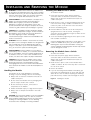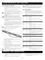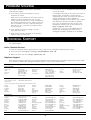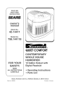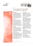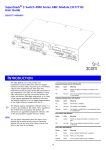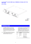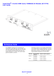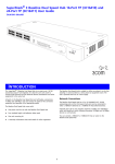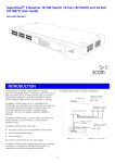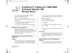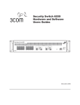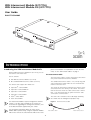
1
XRN Interconnect Module (3C17716) XRN Interconnect Module Kit (3C17715) User Guide DUA1771-5AAA02 (ma Cons x) 1 ole 920 0,8 ,1 ,N S/N : XX XX/7 XXX XXX Unit 1 Unit 2 XXX Act ivity Sta tus 3C1 771 6 X RN Inte rco nne ct M odu le INTRODUCTION Introducing the XRN Interconnect Module Kit panel of the Module. For explanations on how the LEDs work, see the “LED Function Tables” on page 3. With an XRN Interconnect Module Kit (3C17715) you can interconnect two Switch units. The Interconnect Cable This kit contains: Two XRN Interconnect Modules (3C17716) One standard XRN Interconnect Cable (3C17721) The Interconnect Cable is used to interconnect two Switch units, both fitted with Interconnect Modules. The standard Interconnect Cable is 1 m (3.28 ft) long and color-coded with a yellow marker at one end and a blue marker at the other end. The Switches that support this module are: SuperStack® 3 Switch 4900 SuperStack 3 Switch 4900 SX SuperStack 3 Switch 4924 SuperStack 3 Switch 4950 3Com® Switch 4060 3Com Switch 4050 ! The Interconnect Module requires management software version 3.0 or later to be installed on the Switch. For instructions on upgrading the management software, refer to the documentation supplied with your Switch. ! You can gather information about the status of the Module and its packet activity using the Expansion Module LEDs on the front of the Switch and the LEDs on the front The end of the Interconnect Cable that you connect to the Switch determines the identity of the Switch. The Switch that has the blue end of the cable connected to it will be Unit 1. The Switch that has the yellow end of the cable connected to it will be Unit 2. ! The terms Unit 1 and Unit 2 are used simply to identify the Switch units for management purposes only. Figure 1 The Interconnect Cable Blue Marker / Unit 1 1 Yellow Marker / Unit 2 INSTALLING AND REMOVING THE MODULE Installing the Module into a Switch WARNING: Installation and removal of the Module must be carried out by qualified personnel only. Before installing the Module into a unit, you must first disconnect the unit from the mains power supply. For full safety instructions, refer to the user guide that accompanies the unit. To install the Module: 1 Ensure that the power supply and the backbone connection cables are disconnected from the Switch. Always wear an anti-static wristband connected to a suitable earth point. AVERTISSEMENT: Confiez l'installation et la dépose de ce Module à un personnel qualifié. Avant d'installer ce Module dans un groupe, vous devez au préalable débrancher ce groupe de l'alimentation secteur. Pour prendre connaissance des consignes complètes de sécurité, consultez le guide utilisateur qui accompagne ce groupe. 2 Undo the three screws securing the blanking plate at the rear of the Switch using a suitable screwdriver. Do not remove any other screws from the rear of the Switch. 3 Remove the blanking plate. VORSICHT: Die Installation und der Ausbau des Moduls darf nur durch Fachpersonal erfolgen. Vor dem Installieren des Moduls in einem Gerät muß zuerst der Netzstecker des Geräts abgezogen werden. Vollständige Sicherheitsanweisungen sind dem Benutzerhandbuch des Geräts zu entnehmen. 4 Hold the Module so that the text on the front panel is upright and insert it into the Switch, ensuring the connectors are fully engaged (see Figure 2). Make sure the Module is pushed fully in. WARNING: When the Module is inserted into the switch, the captive screws securing the Module must be tightened with a suitable tool. Keep the blanking plate and the fixings in a safe place. If you remove the Module at any time, you must then replace the blanking plate. Keep the blanking plate and screws in a safe place. If you remove the Module at any time, you must replace the blanking plate to prevent dust and debris entering the Switch. Replacing the blanking plate will also help circulate cool air through the Switch. 5 Secure the Module by tightening the three captive screws with a suitable screwdriver. ! AVERTISSEMENT: Quand le Module est inséré dans le commutateur, visser le module, en le securisant fortemant avec un outil adapté. Conservez la plaque d'obturation et les fixations en lieu sûr. Si vous retirez le Module à tout instant, vous devez alors replacer la plaque d'obturation. Removing the Module from a Switch To remove the Module: 1 Ensure that the power supply and the backbone connection cables are disconnected from the Switch. Always wear an anti-static wristband connected to a suitable earth point. VORSICHT: Beim Einsetzen des Moduls in dem Switch sind die unverlierbaren Schrauben mit einem passenden Werkzeug festzuziehen. Die Distanzplatte und die Befestigungselemente an einem sicheren Ort aufbewahren. Beim Austausch des Moduls ist auch die Distanzplatte zu ersetzen. 2 Undo the three captive screws on the Module with a suitable screwdriver. Do not remove any other screws from the rear of the Switch. 3 Remove the Module. Handling the Module 4 If you are not fitting another Module immediately, you must replace the blanking plate to ensure that dust and debris do not enter the Switch. Replacing the blanking plate will also help circulate cool air through the Switch. The Module can be easily damaged by electrostatic discharge. To prevent damage, observe the following: Always wear an anti-static wristband connected to a suitable earth point. Do not remove the Module from its packaging until you are ready to install it into a Switch. Do not touch any of the pins, connections or components on the Module. Figure 2 Serial ! Handle the Module only by its edges and front panel. Always store or transport the Module in anti-static packaging. MA Installing the Module Switch 3C1774900 00 XX No X/X dr: XX XXXXXX XXX XXXX XXXX XX C Ad SUP PLY DATA V90 240 Hz 50/ 60 A 4.5 I REFE R TO MANUA INST L FOR RUCTION COR REC T CAUTION: The Interconnect Module is not hot-swappable or hot-insertable. Always make sure that the Switch is powered down and disconnected from the mains before installing or removing a Module. Use the following instructions when installing or removing a Module. (max Console ) 19 200, 8,1, N INPUT V 27 A Ma x 12 S/N: XXXX /7XXX XXXX XX Unit 1 Unit 2 Activ ity Stat us 3C17 716 2 XRN Inter conn ect Mod ule INTERCONNECTING TWO SWITCHES Interconnecting Two Switches ! To interconnect two Switches, you will need the XRN Interconnect Module Kit (part number 3C17715). This kit contains: Two XRN Interconnect Modules (3C17716) One standard XRN Interconnect Cable (3C17721) LED Function Tables You can gather information about the status of the Module and its packet activity using the Expansion Module LEDs on the front of the Switch (see Table 1) and the Port LEDs on the front panel of the Module (see Table 2). You can interconnect two Switch units that are located in separate racks with a 5 m (16.40 ft) long Interconnect cable (3C17722). Contact your network supplier for further information. ! Table 1 CAUTION: It is important that you only plug an XRN Interconnect Cable (3C17721 or 3C17722) into the connector on the XRN Interconnect Module (3C17716). ! Serial Color Meaning On Yellow Packets are being transmitted or received on the Module. Off No color There are no packets being transmitted or received on the Module. Status Color Meaning Off No color The Module is not installed. Flashing Yellow The Module is installed but is not recognised (faulty or unsupported). The terms Unit 1 and Unit 2 are used simply to identify the Switch units for management purposes only. On Yellow The Module is installed but no link is present. On Green The Module is installed and a link is present. Figure 3 Unit 1—4 LED Interconnecting Two Switches Unit 1: Blue End of Cable Switc h 3C17 4900 700 XXX/X No Addr: Status Expansion Module Status LED The end of the Interconnect Cable that you connect to the Switch determines the identity of the Switch. The Switch that has the blue end of the cable connected to it will be Unit 1. The Switch that has the yellow end of the cable connected to it will be Unit 2. MAC Switch LED Function Table Expansion Module Activity LED Connecting any other 9-way plug into the connector on the XRN Interconnect Module could result in damage to your hardware. ! CAUTION: 3Com recommends that you do not connect or disconnect the Interconnect Cable when the Switches are in use. If you do, the flow of data will be affected and your network configuration settings may change. Status Color Meaning On Green Determines the identity of the Switch when interconnected to another Switch to create an XRN Distributed Fabric and that a link is present. Off No color A fault has occurred. XXXX XXXX XXXX X XXXX XXXX SUPP LY DATA V90 240 Hz 50/60 A 4.5 I REFER MANUTO INSTRU AL FOR CTION CORRE CT INPU V 27 T A Max 12 (ma Console x) 192 00,8 ,1,N S/N: XXX Unit 1 Unit 2 X/7X XXX XXX XX Activity Stat us Serial MAC 3C1 771 6 XRN Inte rcon nect Mod Unit 2: Yellow End of Cable Switc h 3C17 4900 700 XXX/X No Addr: XXXX XXXX XXXX X XXXX XXXX ule SUPP LY DATA V90 240 Hz 50/60 A 4.5 I REFER MANUTO INSTRU AL FOR CTION CORRE CT INPU V 27 T A Max 12 Table 2 (ma Console x) 192 00,8 ,1,N S/N: XXX X/7X XXX XXX XX Unit 1 Unit 2 Module LED Function Table Activity Stat us Activity LED 3C1 771 6 XRN Inte rcon nect Mod ule Status Color Meaning On Yellow Packets are being transmitted or received on this port. 1 Install the Interconnect Modules into the Switch units, as described on page 2. Off No color There are no packets being transmitted or received on this port. 2 Connect the Interconnect Cable to the Interconnect Modules (see Figure 3). Status LED Status Color Meaning 3 Power-up the Switch units. On Green A link is present and the port is enabled. 4 Check the LEDs on the front of the Switch and on the front panel of the Module to ensure that the Module is operating correctly. Refer to the “LED Function Tables” for more information. Off No color There is no link present. To interconnect two Switches: ! Unit 1—2 LED Always secure the Interconnect Cable to the Interconnect Modules by tightening its securing screws. Status Color Meaning On Green Determines the identity of the Switch when interconnected with another Switch. The LEDs indicate ‘Unit 1’ and ‘Unit 2’ respectively. MODULE PORT RESTRICTIONS When using the Interconnect Module, note the following: Only one Interconnect Module may be fitted into the Switch. The Interconnect Module is not hot-swappable. 3 The Interconnect Module is not hot-insertable. The Interconnect Module only operates with the Switch units listed on page 1. . PROBLEM SOLVING If you suspect a problem, carry out these steps before contacting your supplier: Check that the Interconnect Module is correctly installed in the Switch. If the Module Status LED on the front of the Switch is flashing yellow, the Module is installed but not supported by the Switch. The Switch will continue to operate normally but you must upgrade the management software on the Switch for it to recognize and support the Module and enable the Module’s ports. You can download the latest version of the management software from the 3Com website at: http://support.3com.com When you insert the Module into the Switch, push the Module in until the Module’s back plate is in full contact with the Switch’s chassis. Secure the Module to the Switch by tightening the three captive screws fully with a screwdriver. If an error is indicated during the Power On Self Test, check that the module has been correctly inserted. Check that the Interconnect cabling is correctly connected and secured. Check that the Switch, into which the Interconnect Module is fitted, is powered-up. Check that the correct management software is being used on the Switch. Alternatively, if you received a CD-ROM with your Module, you can upgrade your Switch with the management software contained on the CD-ROM. . TECHNICAL SUPPORT If you require assistance, contact your Network Supplier first. If you require further assistance, the following options are available for technical support: Online Technical Services 3Com offers worldwide product support 24 hours a day, 7 days a week, through the following online systems: Check the 3Com knowledgebase at http://knowledgebase.3com.com Browse the 3Com web site on http://www.3com.com Telephone Support Please have your product model name, part number, hardware revision number and serial number along with all relevant details of the problem to hand before calling your Network Supplier or 3Com on the numbers below. Country Asia, Pacific Rim Australia Hong Kong India Indonesia Japan Telephone Number Country Telephone Number Country Telephone Number 1 800 678 515 800 933 486 +61 2 9424 5179 or 000800 650 1111 001 803 61009 00531 616 439 or 03 5977 7991 Malaysia New Zealand Pakistan Philippines 1800 801 777 0800 446 398 +61 2 9937 5083 1235 61 266 2602 or 1800 1 888 9469 10800 61 00137 or 021 6350 1590 or 00800 0638 3266 Singapore S. Korea Taiwan Thailand 800 6161 463 00798 611 2230 or 02 3455 6455 00801 611 261 001 800 611 2000 Hungary Ireland Israel Italy Luxembourg Netherlands Norway 06800 14466 1800 509359 1800 943 2632 199 161346 800 29880 0900 777 7737 815 33 047 Poland Portugal South Africa Spain Sweden Switzerland U.K. 00800 441 1357 707 200 123 0800 991196 9 021 60455 07711 14453 08488 50112 0870 241 3901 Colombia Costa Rica Curacao Ecuador Dominican Republic Guatemala Haiti Honduras Jamiaca Martinique Mexico AT&T +800 998 2112 AT&T +800 998 2112 1 800 998 2112 AT&T +800 998 2112 AT&T +800 998 2112 AT&T +800 998 2112 57 1 657 0888 AT&T +800 998 2112 1 800 998 2112 571 657 0888 01 800 849CARE Nicaragua Panama Paraguay Peru Puerto Rico Salvador Trinidad and Tobago Uruguay Venezuela Virgin Islands AT&T +800 998 2112 AT&T +800 998 2112 54 11 4894 1888 AT&T +800 998 2112 1 800 998 2112 AT&T +800 998 2112 1 800 998 2112 AT&T +800 998 2112 AT&T +800 998 2112 57 1 657 0888 P.R. of China Europe, Middle East and Africa From anywhere in these regions, call: +44 (0)1442 435529 phone From the following countries, you may use the numbers shown: Austria Belgium Denmark Finland France Germany 01 7956 7124 070 700 770 7010 7289 01080 2783 0825 809 622 01805 404 747 Latin America From the Caribbean, Central and South America, call: Antigua Argentina Aruba Bahamas Barbados Belize Bermuda Bonaire Brazil Cayman Chile 1 800 988 2112 0 810 444 3COM 1 800 998 2112 1 800 998 2112 1 800 998 2112 52 5 201 0010 1 800 998 2112 1 800 998 2112 0800 13 3COM 1 800 998 2112 AT&T +800 998 2112 North America 1 800 876 3266 4 . TECHNICAL SPECIFICATIONS Operating Temperature 0 to 40°C (32 to 105°F) Operating Humidity 10 to 95% non-condensing Power Consumption 3 W maximum Safety Standards UL 1950, EN 60950, CSA 22.2#950-93, IEC 950, AS/NZS 3260 Electromagnetic Compatibility ICES-003 Class A, FCC Part 15 Class A, EN55022 Class A, VCCI Class A, AS/NZS 3548 Class A, CISPR22 Class A, CNS 13438 Class A, Korean EMI Class A REGULATORY NOTICES FCC Statement CE Statement (Europe) This equipment has been tested and found to comply with the limits for a Class A digital device, pursuant to part 15 of the FCC rules. These limits are designed to provide reasonable protection against harmful interference when the equipment is operated in a commercial environment. This equipment generates, uses and can radiate radio frequency energy and, if not installed and used in accordance with the instructions, may cause harmful interference to radio communications. Operation of this equipment in a residential area is likely to cause harmful interference to radio communications, in which case the user will be required to correct the interference at their own expense. This product complies with the European Low Voltage Directive 73/23/EEC and EMC Directive 89/336/EEC as amended by European Directive 93/68/EEC. CSA Statement This Class A digital apparatus meets all requirements of the Canadian interference-Causing Equipment Regulations. Cet appareil numérique de la classe A respecte toutes les exigences du Règlement sur le matériel brouilleur du Canada. VCCI Statement Information To The User If this equipment does cause interference to radio or television reception, which can be determined by turning the equipment off and on, the user is encouraged to try to correct the interference by one or more of the following measures: Reorient the receiving antenna. Relocate the equipment in relation to the receiver. Move the equipment away from the receiver. Plug the equipment into a different outlet so that equipment and receiver are on different branch circuits. BSMI Statement If necessary, the user should consult the dealer or an experienced radio/television technician for additional suggestions. The user may find the following booklet prepared by the Federal Communications Commission helpful: How to Identify and Resolve Radio-TV Interference Problems This booklet is available from the U.S. Government Printing Office, Washington, DC 20402, Stock No. 004-000-00345-4. In order to meet FCC emissions limits, this equipment must be used only with cables which comply with IEEE 802.3. 5 T LEGAL NOTICES For civilian agencies: Restricted Rights Legend: Use, reproduction or disclosure is subject to restrictions set forth in subparagraph (a) through (d) of the Commercial Computer Software - Restricted Rights Clause at 48 C.F.R. 52.227-19 and the limitations set forth in 3Com Corporation’s standard commercial agreement for the software. Unpublished rights reserved under the copyright laws of the United States. © 3Com Corporation, 2002. All rights reserved. No part of this documentation may be reproduced in any form or by any means or used to make any derivative work (such as translation, transformation, or adaptation) without permission from 3Com Corporation. 3Com Corporation reserves the right to revise this documentation and to make changes in content from time to time without obligation on the part of 3Com Corporation to provide notification of such revision or change. If there is any software on removable media described in this documentation, it is furnished under a license agreement included with the product as a separate document, in the hard copy documentation, or on the removable media in a directory file named LICENSE.TXT. If you are unable to locate a copy, please contact 3Com and a copy will be provided to you. 3Com Corporation provides this documentation without warranty of any kind, either implied or expressed, including, but not limited to, the implied warranties of merchantability and fitness for a particular purpose. 3Com may make improvements or changes in the product(s) and/or the program(s) described in this documentation at any time. UNITED STATES GOVERNMENT LEGENDS: If you are a United States government agency, then this documentation and the software described herein are provided to you subject to the following restricted rights: Unless otherwise indicated, 3Com registered trademarks are registered in the United States and may or may not be registered in other countries. 3Com and SuperStack are registered trademarks of 3Com Corporation. Other brand and product names may be registered trademarks or trademarks of their respective holders. For units of the Department of Defense: Restricted Rights Legend: Use, duplication or disclosure by the Government is subject to restrictions as set forth in subparagraph (c) (1) (ii) for restricted Rights in Technical Data and Computer Software clause at 48 C.F.R. 52.227-7013. 3Com Centre, Boundary Way, Maylands Park South, Hemel Hempstead, Herts, HP2 7YU, U.K. ENVIRONMENTAL STATEMENTS General Environmental Statement End Of Life Statement It is the policy of 3Com Corporation to be environmentally-friendly in all operations. To uphold our policy, we are committed to: 3Com processes allow for the recovery, reclamation and safe disposal of all end-of-life electronic components. Establishing environmental performance standards that comply with national legislation and regulations Conserving energy, materials and natural resources in all operations Reducing the waste generated by all operations Ensuring that all waste conforms to recognized environmental standards Maximizing the recyclable and reusable content of all products Ensuring that all products can be recycled, reused and disposed of safely Ensuring that all products are labelled according to recognized environmental standards Improving our environmental record on a continual basis Regulated Materials Statement 3Com products do not contain any hazardous or ozone-depleting material. Environmental Statement about the Documentation The documentation for this product is printed on paper that comes from sustainable, managed forests; it is fully biodegradable and recyclable, and is completely chlorine-free. The varnish is environmentally-friendly, and the inks are vegetable-based with a low heavy-metal content. Product Registration You can now register your Interconnect Modules (3C17716) on the 3Com web site at: http://support.3com.com/registration/frontpg.pl From the Product Registration page, select the Product Category “Switches”. ! You cannot register the Interconnect Kit (3C17715). You can only register the individual modules with their associated serial numbers. Documentation Feedback Your suggestions are very important to us. They will help make our documentation more useful to you. Please e-mail comments about this document to 3Com at: [email protected] Please include the following information when commenting: the document title, part number and page number, if appropriate. Part Number: DUA1771-5AAA02 Published: December 2002 6