1
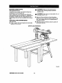
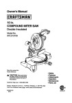
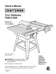
Owner's Manual
[I:RRFTSMRN'[
i
PROFESSIONAL
I
10 in. Stationary
RADIAL ARM SAW
Model No.
315.220380
Save this manual for
future reference.
CAUTION:
Read and follow all
Safety Rules and Operating
Instructions before first use of this
product.
Customer Help Line: 1-800-932-3188
Sears, Roebuck and Co., Hoffman Estates, IL 60179 LISA
visit the Craftsman web page: www.sears.com/craftsman
972000-505
3-99
•
•
•
•
•
•
Safety
Features
Assembly
Operation
Maintenance
Parts List
®
FULL ONE YEAR WARRANTY ON CRAFTSMAN RADIAL ARM SAW
If this CItRFTSMRN'Radial Arm Saw fails,dueto a defect in material or workmanshipwithin one year from the
date of purchase, Sears will repair it, free of charge.
Contact a Sears Service Center for repair.'
If this product is used for commercial'orrental purposes, this warrantyapplies only for 90 days from the date of
purchase.
This warranty gives you specificlegal rights,and you may also have other rights whichvary from state to state.
Sears, Roebuck and Co., Dept. 817WA, Hoffman Estates, IL 60179
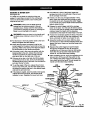
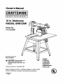
Your saw has many features for making cuttingoperations more pleasantand enjoyable. Safety, performance
and dependability have been given top priorityin the design of this saw making it easy to maintain and operate.
_l,
CAUTION: Carefully read through this entire owner's manual before using your new saw. Pay close
attention to the Rules For Safe Operation, and all Safety Alert Symbols, includingDanger, Warning and
Caution. If you use your saw properly and only for what it is intended,you will enjoy years of safe, reliable
service.
_k
Look for this symbol to point out important safety precautions.
involved.
,_
WARNING:
It means attentionf!! Your safety is
The operation of any power tool can result in foreign objectsbeing thrown into your eyes,
whichcan resultin severe eye damage. Before beginningpower tool operation,always wear
safety gogglesor safety glasses with side shields and a full face shield when needed. We
recommend Wide Vision Safety Mask for use over eyeglasses or standard safety glasses
with side shields, available at Sears Retail Stores.
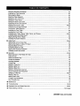
• Warranty and Introduction ...............................................................................................................................
2
• Table of Contents..........................................................................................................................................
2-3
• Rules For Safe Operation.............................................................................................................................
4-7
• Electrical........................................................................................................................................................
8-9
• ProductSpecificationsand Glossary........................................................................................................
• Unpacking and Accessories ..........................................................................................................................
• Loose Parts List ........................................................................................................................................
• Tools Needed .................................................................................................................................................
10-t 1
11
12-14
15
• Labels........................................................................................................................................................
16-17
• Features ....................................................................................................................................................
18-21
• Assembly...................................................................................................................................................
22-36
Assembling Leg Stand ...................................................................................................................................
22
Mounting Saw to Leg Stand ...........................................................................................................................
23
I:RRFTSNRN"
RADIALSAW315.220380
2
AttachingElevating Handwheel .....................................................................................................................
Installingthe Yoke Assembly.........................................................................................................................
Removing the Blade.......................................................................................................................................
AttachingTable Supports ..............................................................................................................................
Setting the Arm Lock Knob ............................................................................................................................
Setting the Yoke Clamp .................................................................................................................................
Setting the Bevel Lock Lever .........................................................................................................................
Tightening the Arm and Column....................................................................................................................
23
24
25
25
26
26
27
28
Adjustingthe Column Tube ...................................................................................................................... 28-29
Adjustingthe Carriage Bearings.................................................................................................................... 30
Levelingthe Table Supports..........................................................................................................................
31
Installingthe FrontTable ...............................................................................................................................
32
Levelingthe Front Table ................................................................................................................................
33
InstallingRear Table, Spacer Table, Fence, and Clamps........................................................................ 33-34
Installing Blade and Blade Guard .................................................................................................................. 34
Aligning Riving Knifeto Blade........................................................................................................................
35
InstallingRip Scale Indicators........................................................................................................................
36
:
• Adjustments ................................................................ :;,............................................................................ 36-42
Aligningthe Arm for Cross Cuts .................................................................................................................... 37
Aligningthe Blade to Table at 0" Bevel .........................................................................................................
Squadng Blade to Fence ...............................................................................................................................
Paralleling Blade to Table ..............................................................................................................................
Aligningthe Rip Scale Indicators ...................................................................................................................
InstallingControl Cut Device .........................................................................................................................
•
.
Operation ..................................................................................................................................................
38
39
40
41
42
43-53
Basic Operation of the Radial Arm Saw ........................................................................................................
Types of Cuts .................................................................................................................................................
Switch and Switch Key...................................................................................................................................
Causes of K_ckback.......................................................................................................................................
43
43
44
44
AvoidingKickback..........................................................................................................................................
CuttingAids ....................................................................................................................................................
44
45
Making a Cross Cut .......................................................................................................................................
46
Making a Miter Cut .........................................................................................................................................
47
Making a Bevel Cut ........................................................................................................................................
48
Making a Compound Cross Cut ..................................................................................................................... 49
Rip Cut Hazards and Precautions................................................................................................................. 50
Setting Up a Rip Cut ................................................................................................................................. 50-51
Making a Rip Cut ...........................................................................................................................................
51
Making Other Cuts .........................................................................................................................................
52
Cutting Long Workpieces...............................................................................................................................
52
Non-Through Cuts .........................................................................................................................................
53
• Maintenance ..................................................................................................................................................
54
• Troubleshooting........................................................................................................................................
55-59
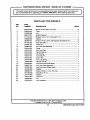
•
ExplodedView and Repair Parts Ust .......................................................................................................
60-81
•
Parts Ordering / Service ....................................................................................................................
3
back page
CRIIFTSHAN"
RADIALSAW315.220380
The purpose of safety symbols is to attract your attention to possible dangers. The safety symbols, and
the explanations with them, deserve your careful attention and understanding. The safety warnings do
not by themselves eliminate any danger. The Instructions or warnings they give ere not substitutes for
proper accident prevention measures.
MEANING
SYMBOL
SAFETY ALERT SYMBOL
Indicatesdanger, warningor caution.May be used in conjunctionwith othersymbolsor
pictographs.
A
DANGER: Failure to obey a safety warningwill resultin serious injuryto yourselfor to others.
Always follow the safety precautionsto reduce the risk of fire, electricshock and personalinjury.
A
WARNING: Failureto obey a safety warningcan resultin serious injuryto yourselfor to others.
Always follow the safety precautionsto reduce the risk of fire, electricshock and personalinjury.
&
CAUTION: Failure to obey a safety warning may resultin propertydamage or personalinjuryto
yourselfor to others. Always follow the safety precautionsto reducethe risk of fire, electdcshock
and personalinjury.
Note:
Advisesyou of informationor instructionsvital to the operationor maintenance of the equipment.
IMPORTANT
_l,
WARNING: Do not attemptto operate this tool
untilyou have read thoroughlyand understand
completely all instructions,safety rules, etc.
contained in this manual. Failure to comply can
resultin accidentsinvolvingfire, electdc shock,
or sedous personal injury. Save owner's manual
and review frequently for continuing safe
operation,and instructingothers who may use
this tool.
•
MAKE WORKSHOP CHILD-PROOF with padlocks
and master switches or by removingswitch keys.
•
USE THE RIGHT TOOL FOR THE JOB. Do not
force the tool or attachment to do a job it was not
designedfor. Use it onlythe way it was intended.
Servicing requiresextreme care and knowledge of the
system and shouldbe performedonly by a qualified
service technician.For service we suggestyou contact
your nearest Sears repair center. Always use odginal
factory replacement parts when servicing.
If you have questionsabout terms in the following
rules, refer to the Glossary of Terms for Woodworking
or the Features section.
READ ALL INSTRUCTIONS
KNOW YOUR POWER TOOL.Read the owner's
manual carefully. Learn the saw's applicationsand
limitationsas well as the specificpotential hazards
related to this tool.
•
DO NOT USE IN DANGEROUS ENVIRONMENT.
Do not use power tools near gasoline or other
flammable liquids,in damp or wet locations,or
expose them to rain. Keep the work area well lit.
•
KEEP CHILDREN AND VISITORS AWAY. All
visitors shouldwear safety glasses and be kept a
safe distance from work area. Do not let visitors
contact the tool or extension cord while operating.
•
DRESS PROPERLY, Do not wear loose clothing,
gloves, neckties, rings,bracelets, or otherjewelry.
They can get caught and draw you into moving
pads. Nonslip footwear is recommended. Also
wear protectivehair covedng to contain long hair.
ALWAYS WEAR SAFETY GLASSES WITH SIDE
SHIELDS. Everyday eyeglasses have only impactresistantlenses; they are NOT safety glasses.
• NEVER STAND ON TOOL. Sedous injurycould
occur if the tool is tipped or if the blade is unintentionallycontacted.
KEEP WORK AREA CLEAN. Cluttered work
areas and work benches inviteaccidents. DO NOT
leave tools or pieces of wood on the sew while it is
in operation. Keep floors clean and free of sawdust.
• MAINTAIN TOOLS WITH CARE. Keep tools sharp
and clean for better and safer performance. Follow
instructionsfor lubricatingand changing accessodes.
I]IIIFTSHIIN"
RADIAL SAW 315.220380
4
•
DO NOT OVERREACH. Keep proper footingand
balance at all times.
•
SECURE WORK. Use clamps or a vise to hold
work when practical. It's safer than using your
hand and frees both hands to operate the tool.
n USE THE PROPER EXTENSION CORD. Make
sure your extension cord is in good condition,Use
onlya cord heavy enough to carry the current your
productwill draw. An undersizedcord will cause a
drop in linevoltage resultingin loss of power and
overheating.A wire gage size (A.W.G.) of at least
14 is recommendedfor an extension cord 25 feet
or less in length. If in doubt,use the next heavier
gage. The smaller the gage number, the heavier
the cord.
DISCONNECT ALL TOOLS. When not in use,
before servicing, or when changing attachments,
blades, bits,cutters, etc., all tools should be
disconnectedfrom the power supply.
• DO NOT FORCE THE TOOL. It will do the job
better and more safely at the rate for which it was
designed.
•
M AVOID ACCIDENTAL STARTING. Be sure switch
is off when pluggingin the tool.
•
_IL WARNING: When servicing,use only identical
Craftsman replacement parts. Use of any other
parts may create a hazard or damage product.
REMOVE WRENCHES AND ADJUSTING KEYS.
Get in the habit of checking - before turning on the
tool - that hex keys and adjusting wrenchesare
removed from tool.
NEVER USE THIS TOOL IN AN EXPLOSIVE
ATMOSPHERE. Normal sparkingof the motor
could ignite fumes.
• CHECK DAMAGED PARTS. Before using the tool
again, check any damaged parts, includingguards,
for proper operation and performance.Check
alignmentof moving parts, bindingof movingparts,,
breakage of parts, saw stability,mounting,and any
other conditions that may affect itsoperation. A
damaged part must be propedy repaired or replaced by a qualified service technicianat a Sears
repair center to avoid risk of personal injury.
USE ONLY CORRECT BLADES. Use the right
blade stylefor the material and the type of cut.
Use only blades marked for at least 5,000 rpm and
10 in. or smaller, with e 5/8 in. arbor hole.
•
KEEP GUARDS IN PLACE and In good working
order. This includesthe blade guard,the dving
knife, and the anti-kickback pawls.
•
CHECK DIRECTION OF FEED. When dpping,
feed work into a blade or cutter against the direction of rotation of the blade or cutter.
•
NEVER LEAVE TOOL RUNNING UNAI"rENDED.
TURN THE POWER OFF. Do not leave the tool
until it comes to a complete stop.
•
BEFORE MOUNTING, DISCONNECTING OR
REMOUNTING THE MOTOR; unplugthe saw and
remove the switch key.
•
MAKE SURE THE WORK AREA HAS AMPLE
LIGHTING to see the work and that no obstructionswill interfere with safe operation BEFORE
performingany work usingthis tool.
•
DO NOT USE TOOL IF SWITCH DOES NOT
TURN IT ON AND OFF. Have defective switches
replaced by a qualified service technicianat a
Sears repair center.
•
GUARD AGAINST ELECTRICAL SHOCK by
preventing bodycontact with groundedsurfaces
such as pipes, radiators, ranges, refrigerator
enclosures.
M GROUND ALL TOOLS. See Electrical page.
•
WEAR A DUST MASK to keep from inhalingfine
particles.Use wood dust collectionsystems
whenever possible.
m PROTECT YOUR HEARING. Wear headng
protectionduringextended periodsof operation.
•
USE RECOMMENDED ACCESSORIES. Using
improper accessories may risk injury. Consultthe
Accessories section for recommendedaccessodes.
DO NOT OPERATE THIS TOOL WHILE UNDER
THE INFLUENCE OF DRUGS, ALCOHOL, OR
ANY MEDICATION.
STAY ALERT AND EXERCISE CONTROL. Watch
what you are doingand use common sense. Do
not operate tool when you are fired. Do not
rush.
M USE ONLY SEARS REPLACEMENT PARTS. All
repairs, whether electrical or mechanical,should
be made by a qualified service technicianat a
Sears repair center.
AVOID AWKWARD OPERATIONS AND HAND
POSITIONS where a sudden slipcould cause your
hand to move intothe blade. ALWAYS make sure
you have good balance.
5
CRRFTSNRr
RADfAL
SAW315._80
•
•
GUARD AGAINST KICKBACK, Kickbackcan
occur when the blade stalls, drivingthe work piece
back toward the operator. It can cause your hand
to contact the blade, resultingin serious personal
injury. Stay out of the blade path and turnswitch
off immediately it blade binds or stalls.
ALLOW THE MOTOR TO COME UP TO FULL
SPEED before starting a cut to avoid blade binding
or stalling.
l
ALWAYS PUSH THE WORKPIECE when ripping;
never pull it toward the saw.
DO NOT FEED THE MATERIAL TOO QUICKLY.
Do not force the workpiece against the blade.
DO NOT USE A PERSON AS A SUBSTITUTE
FOR A TABLE if additional supportis needed. Use
a supportthe same height as the table.
•
ALWAYS TURN OFF SAW before disconnecting
it, to avoid accidental starting when reconnecting
to the power supply. NEVER leave the saw
unattendedwhile connectedto a power source.
USE A SUPPORT FOR THE SIDES AND BACK
OF THE SAW TABLE when sawingwide or long
workpieces to minimize the risk of blade pinching
and kickback. Use a sturdy"outrigger" supportto
prevent tippingif a table extension more than 24
inches long is attached to the saw.
•
CUT ONLY WOOD, PLASTIC OR WOOD-LIKE
MATERIALS. Do not cut metal•
•
BEFORE MAKING A CUT, be sure all adjustments
are secure.
I
NEVER cut more than one piece at a tnme.DO
NOT STACK more than one workpiece on the saw
table at a time.
l
DO NOT REMOVE THE SAW'S BLADE GUARD.
Never operate the saw with the blade guard
removed. Make sure all guards are operating
properly before each use.
•
• BEFORE CHANGING THE SETUP, REMOVING
COVERS, GUARDS, OR BLADE; unplugthe saw
and remove the switch key.
BE SURE THE BLADE PATH IS FREE OF
NAILS. Inspect for and remove all nailsfrom
lumber before cutting.
BE SURE THE BLADE CLEARS THE WORKPIECE. Never start the saw with the blade touching
the stock.
•
KEEP HANDS AWAY FROM CUTTING AREA.
Do not reach underneath work or in blade cutting
path with your hands and fingers for any reason.
Always turn the power off when cut is complete.
•
USE A PUSHBLOCK OR PUSHSTICK in rip mode
for workpieces so small that your fingers go under
the blade guard. NEVER TOUCH BLADE or other
moving parts during use, for any reason.
•
KEEP BLADES CLEAN, SHARP AND WITH
SUFFICIENT SET. Sharp blades minimizestalling
and kickback•Keep blades free of rust,grease,
and pitch.
WARNING:
Blade coasts after being turned off.
USE ONLY OUTDOOR EXTENSION CORDS.
Use only extension cordswith the marking "Acceptable for use with outdoor appliances; store
indoorswhile not in use," Use extensioncords with
an electrical rating not less than the saw's rating.
Always disconnectthe extensioncord from the
outlet before disconnectingthe productfrom the
extension cord.
NEVER PERFORM ANY OPERATION FREEHAND. Always place the workpiece to be cut on
the saw table and positionit firmlyagainst the
fence as a backstop.
•
KEEP TOOL DRY, CLEAN, AND FREE FROM
OIL AND GREASE. Always use a clean cloth
when cleaning. Never use brake fluids,gasoline,
petroleum-basedproducts,or any solventsto
clean tool.
_i,
• USE THE RIP FENCE. Always use a fence or
straight edge guide when ripping.
•
•
INSPECT TOOL CORDS AND EXTENSION
CORDS PERIODICALLY and, if damaged, have
repaired by a qualified service technicianat a
Sears repair center. Stay constantly aware of cord
locationand keep it well away from the moving
blade.
DO NOT ABUSE CORD. Never yank the cord to
disconnectit from receptacle. Keep the cord from
heat, oil, and sharp edges.
SAVE THESE INSTRUCTIONS.
Refer to them
frequently and use to instruct other users. If you
loan someone this tool, loan them these instruc-
tionsalso.
SAVE THESEINSTRUCTIONS
IHF{'INAr
RADIALSAW315.220380
6
M SECURE THE SAW. Firmly boltthe saw to the leg
stand to keep the saw from tipping,walking, or
sliding.
B DO NOT SET UP WORK WITH THE BLADE
SPINNING. Keep the saw power off untilyou are
ready to use it.
M RIP ONLY WORKPIECES LONGER THAN THE
BLADE'S DIAMETER. Never rip a piece of wood
that is shorter than the diameter of the blade.
m NEVER LOWER AN UNLOCKED REVOLVING
CUI-rlNG TOOL. Always lock the carriage lock
knob before loweringthe blade.
M SHUT OFF THE POWER TO FREE A JAMMED
GUARD. Press the switchoff before puttingyour
hands near the blade. Wait for the blade to stop,
then free the guard.
B LOCK THE SAW BEFORE MOVING IT. Secure
the radial arm with the arm lock knob. Secure the
carriage with the carriage lock knob.
•
BEFORE CUTTING, positionand tighten the blade
guard and anti-kickback pawls.Test the pawls to
make sure they would stop kickbackif it started.
Keep the points sharp.
M KEEP THE SAW BLADE PATH CLEAR. Position
the saw to allow enough room on all sides so
neither the operator nor a visitorstands in line with
the sawblade.
M AVOID HEELING by adjustingthe saw blade so it
exactly parallelsthe fence during rippingoperations.
M AVOID GRABBING in rip mode by keeping the
saw blade correctly adjusted and by feeding the
work from the infeed side (opposite the antikickbackpawls).
B AVOID PINCHING by using a rivingknife and
sharp saw blade. Keep the work positionedfirmly
against the fence.
B USE IN-RIP WHENEVER POSSIBLE by positioningthe work so the blade is between (inside)the
columnand the motor.
B POSITION THE WORKPIECE WITH THE FINISHED SIDE DOWN. If the anti-kickback pawls
catchthe woodto stop kickback,they could mar
the top surface or cause splintering.
m NEVER ADJUST GUARD, PAWLS, OR BLADE
WITHOUT DISCONNECTING THE POWER.
Always turn off the switch and unplug the cord
before freeing a jammed blade, tighteninga loose
blade, or repositioningthe guard or pawls.
M POSITION THE WORKPIECE SO NO ONE MUST
STAND IN LINE WITH THE BLADE. If kickback or
climb occurs, a helper, operator, or observer in the
sawblade path could be seriouslyinjured.
,_
M POSITION THE CUT SO THE WASTE PART
FALLS OFF. Never use a length stop on the free
end of the workpiece. Never apply force to the free
end or hold it while the sawblade is rotating.
CAUTION: Do not turn the motor switchon and
off rapidly.This can loosenthe sawblade.
n NEVER CUT MORE THAN ONE PIECE OF
WOOD AT A TIME. The feed will be uneven and
could cause the blade to pick up one or more
pieces and cause serious injury.
WARNING: In a rip cut, holdingthe cut-off edge
behindthe blade can cause the cut edges to
pinch, riskingkickback.It could cause the blade
to climb over the front edge of the wood and
contact your hand.
B TURN OFF SAW IF A STRANGE NOISE OR
HEAVY VIBRATION OCCURS. Immediately turn
off the saw, locate the source, and correct the
problem before using the saw further.
U POSITION THE CUT SO THE BLADE WILL NOT
EXTEND BEYOND THE EDGE OF THE TABLE.
n BEFORE STARTING EACH CUT, check that no
play exists in the carriage. Be sure the arm, yoke
and bevel locks and clamps are tight. Verify the
blade, aUhandles, blade washers, and blade nuts
are secure.
M BEFORE MAKING A CUT, test the upper and
lower blade guards for free movement up and
down. Positionthe nose of the guard to just clear
the workpiece.
M AVOID KICKBACK AND POSSIBLE INJURY by
preventing heeling, grabbing, and pinching.
7
i
KEEP THE GUARDS IN PLACE AND THE WORK
SURFACE CLEAR DURING A CUT. Small objects
or wood sliverscan ricochetfrom the blade intothe
fence and back toward the operator. If the blade
loosensslivers, remove them with a stick, not your
hand.
•
IN A RIP CUT, DO NOT LET GO OF THE WORKPIECE UNTIL THE CUT IS COMPLETE. When the
workpiece is fed into the blade, push the workpiece
all the way past the blade.
CRAFTSHQN'RADIALSAW315.220380
EXTENSION
CORDS
GROUNDINGINSTRUC_ONS
Use only 3-wire extension cordsthat have 3-prong
groundingplugs and 3-pole receptacles that accept
the tool's plug. When using a power tool at a considerable distance from the power source, use an extension cord heavy enough to carry the current that the
tool will drew. An undersizedextension cord will
cause a drop in line voltage, resultingin a loss of
power and causing the motor to overheat. Use the
chart provided below to determine the minimumwire
size required in an extension cord. Only roundjacketed cords listed by Underwriter'sLaboratories(UL)
should be used.
Length of Extension Cord
In the event of a malfunctionor breakdown, grounding
providesa path of least resistancefor electriccurrent
to reduce the riskof electricshock.This tool is
equipped with an electriccord having an equipmentgroundingconductorand a groundingplug. The plug
must be plugged intoa matchingoutlet that is propedy
installedand groundedin accordance with all local
codes and ordinances.
Do not modifythe plug provided. If it willnot fit the
outlet, have the properoutlet installedby a qualified
electrician. Improperconnectionof the equipmentgroundingconductorcan result in a risk of electric
shock. The conductorwith insulationhaving an outer
surface that is green with or withoutyellow stripesis
the equipment-groundingconductor.If repair or
replacement of the electriccordor plug is necessary,
do not connectthe equipment-groundingconductorto
a live terminal.
Wire Size (A.W.G.)
Up to 25 feet
26-100 feet
14
12
When workingwith the tool outdoors,use an extension cord that is designed for outside use. This is
indicated by the letters WA on the cord'sjacket.
Before using an extension cord, inspectit for Looseor
exposed wires and cut or worn insulation.
Check with a qualifiedelectricianor service personnel
if the groundinginstructionsare not completely
understood,or if in doubt as to whether the tool is
properlygrounded.
Repair or replace a damaged or worn cord immediately.
_1_ CAUTION: Keep the cord away from the cutting
area and positionthe cord so that it will not be
caught on lumber, tools, or other objectsdudng
cutting operations.
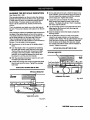
ELECTRICAL
This tool is intendedfor use on a circuitthat has an
outlet like the one shownin Figure I. It also has a
groundingpin like the one shown.
CONNECTION
Your Sears Craftsman Radial Arm Saw is powered by
a precisionbuilt electric motor. It shouldbe connected
to a power supply that Is 120 volts, 60 Hz, AC only
(normal household current). It should be connected
to a 240 volt power supply only If It has been reset
according to the Instructions in this manual. The
motor has been set at the factory for 120 volts; if it is
reconnectedto operate at 240 volts,the main power
cord plug and any receptacle must be replaced with
devices rated for 240 volts. This tool will not operate
on direct current (DC). A substantialvoltage drop will
cause a loss of power and the motorwill overheat. If
the saw does not operate when plugged intoan outlet,
double check the power supply.
SPEED
1
PIN
AND WIRING
COVEROFGROUNDED
OUTLETBOX
The no-load speed of your saw is approximately3,600
rpm. This speed is not constant. For voltage, the
wiring in a shop is as importantas the motor's horsepower rating. A line intendedonly for lightscannot
propedy carry a power tool motor. Wire that is heavy
enough for a shortdistance will be too light for a
greater distance. A line that can supportone power
tool may not be able to supporttwo or three tools.
CRAFTSMAN"
RADIAL SAW 315,220380
8
Fig. 1
LIFTMOTORCOVERTOEXPOSESWITCH
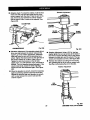
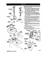
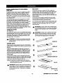
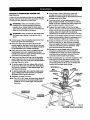
CHANGING VOLTAGE
See Figures 2-4.
Your radial saw has been set up at the factoryto
operate efficientlyon a 120V AC single voltagecircuit.
However, if heavy duty operation is required,the
circuitsare overloaded, or the circuitis low voltage,
have a qualified electdcian change the voltage on the
main power system to a 240V AC voltage circuit.
_l,
WARNING: The controlcut device is set up for
a 120V AC single voltage circuit.Do not modify
the control cut cord. Identifythe controlcut
cord and tie it back out of the way.
• Correctly identifythe controlcut cord, unplugit,
and set it aside.
•
Unplug the main power cord.
•
Remove the blade following the procedure in the
Assemblysection.
SUDEASSHOWNFORSINGLEVOLTAGE
CIRCUITS
SWITCHSHOWNIN 110-120VOLTPosmoN
Fig. 3
• Remove the pan head screw above the blade
arbor on the motorcover. Lift motor cover to
expose switch.See Figure 2.
• Use a small screwdriverto slidethe dual voltage
switchto the 240V position. See Figures3 and 4.
• Reinstall motorcover.
•
LIFTMOTORCOVERTOEXPOSESWITCH
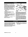
Replace the 120V plug on the main cordwith a UL
listed 240V, 15 amp, 3-prong plug.
• Follow the instructionsprovided with the UL listed
plug.
• Plugthe cord into a 240V, 15 amp, 3-blade receptacle. Make sure the receptacle is connected to a
240V AC power supply through a 240V'bmnch
circuitthat has a 15 amp fuse or circuit breaker.
Note: No adapter is available for this type of plug or
receptacle.
M_ORC_ER
PANHEADSCREW
SLIDEASSHOWNFORDUN.VOLTAGE
CIRCUITS
SWITCHSHOWNIN 220-240VOLTPOSmON
Fig. 4
0
BLADEARBOR
Fig. 2
9
CnFT|NIIN"RADIAL
SAW315.220380
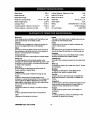
Blade Arbor
5/8 in.
Blade Diameter
Blade Bevel Angle
Radial Arm Swing Range
Depth of Cut at 90"
3 in.
0" - 90"
Depth of Cut at 45"
2.25 in.
50" left - 90" right
Blade Height Adjust
16 in.
Cutting Capacity - Maximum In-Rip
10 in.
Table Size
36 in.
Table Height
5.35 in.
Carriage Travel
17.25 in.
Rating
Cutting Capacity - MaximumCross Cut
15.50 in.
Input
Cutting Capacity - Maximum Out-Rip
40 x 27.75 x 1 in.
No Load Speed
26 in.
120V/240V 60 Hz - AC only
13.0/6.5 Amperes
3,600 RPM
Bevel Cut
A cut made across a workpiece with the blade at any
angle other than 90 ° to the table surface.
Chamfer
A cut removinga wedge from a blockso the end (or
part of it) is angled ratherthan at 90 degrees.,
Infeed
The side of the blade where the blade teeth point up,
oppositethe anti-kickbackpawls.
Climb
A hazard in which the blade =climbs" over and out of
the workpiece, pullingthe stockout of the operator's
hands or runningacross the workpiece.
Kerr
The space left by the removal of material in a cut or
the slot produced by the blade in a non-throughcut.
In-Rip
A type of ripcut in whichthe blade is between the
column and the motor.
Kickback
A hazard that can occurwhen blade bindsor stalls,
throwingworkpieceback towardoperator.
Compound Cut
A cross cut with both a miter angle and a bevel angle.
Cross Cut
A cuttingoperation with the blade parallel to the
carriage arm and the blade teeth pointingdown. It can
be across or with the grain, normallyacross the grain
or width of the workpiece.
Leading End
The end of the workpiece pushed intothe cuttingtool
first.
Miter Cut
A verticalcut made at any angle other than 0" across
the workpiece.
Dado Cut
A non-throughcut that leaves a square notchor
trough; requires a specialblade.
Molding
A shaping cutthat gives a vaded shape to the
workpiece and requiresa specialblade.
Featherboard
A device to help guide workpieces during rip cuts.
Out-Rip
A type of ripcut in which the motoris between the
blade and the column. (The blade is "outside"the
motor).
Fence
A piece of wood used as a edge guide for the
workplace. Located perpendicularto the carriage arm.
Can be placed at different distancesfrom the rear
table edge in combinationwith the other table pieces
and is secured with table clamps.
Pushatlck
A device used to feed the workpiece throughthe saw
blade duringcutting operations.It helps keep the
operator'shands well away from the blade.
Rabbet
A type of cut that gives a notchin the edge of a
workpiece.
Resaw
A cuttingoperationto reducethe thicknessof the
workplaceto make thinner pieces.
Freehand
Dangerous practice of makinga out withoutusing a
fence.
Gum
A sticky, sap-based residue from wood products.
Heel
Alignment of the blade to the fence.
(IIRR'$NRIr RADIALSAW315.220380
10
Resin
A sticky, sap-based substance.
Throw-Back
Saw throwing back a workpiece similar to kickback.
Rip Cut
"
In a radial saw, a cut made with the blade parallel to
the fence and perpendicularto the arm. Can be
across or with the grain. The teeth point up at the
point of contact with the wood,
Through Sawing
AnyCutting operation where the blade extends
completely through the workpieca.
Sawblade Path
The area directly in line with the blade -- over, under,
behind, or in frontof it. Also, the workpiece area which
will be or has been cut by the blade.
Workplace
The item on which the cuttingoperation is being done.
The surfaces of a workpiece are commonly referred to
as faces, ends, and edges.
Set
The distance that the tip of the saw blade tooth is off
sat from the face of the blade.
Worktable
The surface on which the workpieca restswhile
performinga cutting operation.
To prevent accidental startingthat
,& WARNING:
could cause possibleserious personalinjury,
•
Carefully remove all parts from the carton and
place the saw on a level work surface. Separate
and check againstthe list of loose parts.
•
Do not discard the packing materials until you have
carefully inspectedthe saw, identifiedall parts,and
satisfactorilyoperated your new saw.
assemble all parts to your saw before connecting
it to power supply.The saw shouldnever be
connected to the power supplywhen you are
assembling parts, making adjustments,installing
or removingblades, or when not in use.
_,
WARNING: If any parts are missing,do not
operate this tool untilthe missing parts are
replaced. Failure to do so could resultin possible
serious personal injury.
Trailing End
The workpiece end last cut by the blade in a ripcut.
Note: If any parts are damaged or missing,do not
attempt to plug in the power cord and turn the
switchon untilthe damaged or missing parts
are obtained and are installedcorrectly.
The followingrecommendedaccessoriesare currentlyavailable at Sears Retail Stores.
• Steel and carbide tipped circularsaw blades
• Hold down clamps
• Saw baskets
WARNING:
• Adjustable taper jig
• Sawdust collectorshroud
The use of attachments or accessories not listed mightbe hazardous.
11
CRIIFTSNRN"
RADIAL
SAW315.220380
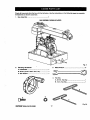
Checkall loose parts from the box with the list below. Use the instructionson the followingpages to assemble.
Allfasteners are shown actual size.
f.
Saw Assembly.................................................... 1
SAWASSEMBLY
SHOWNASPACKED
Fig. 5
21
3; Blade Wrench .......... ;.......................................... 2
Elevating Handwheel
A. Handwheel ................................................... ;. 1
B. Screw (10-24 x 5/8 In. Soc. Hd.) .................... 1
C. Star Washer ................................................... 1
4.
Hex Key
A. 3/16 In. Hex Key............................................. 1
B. 1/4 in. Hex Key ............................................... 1
c
Fig. 6A
(IUImMlUr
RADIALSAWS15._,0_180
12
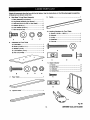
Checkall
loose parts from the box with the list below. Use the Instructions on the followingpages to assemble.
All fasteners are shown actual size.
9.
Saw Base To Leg Stand Assembly
5.
Fence .................................................................. 1
A. Saw Assembly(not shown) ........................... 1
B. Leg Stand Assembly (not shown) .................. 1
C. Hex bolt (5/16-18 x 5/8 in. Hex Head) ........... 4
D. Washer (5/16 in.) ........................................... 8
E. Lock washer (5/16 in.) ................................... 4
F. Hex Nut (5/16-18) ........................................... 4
10. Leveling Hardware for Front Table
A. Screw (1/4-20 x 1-3/4 in.) .............................. 1
B. Washer ........................................................... 1
C
6.
D
E
C. U-clip.............................................................. 1
D. Setscrew ........................................................ 1
F
E. Tee nut ........................................................... 1
Hardware for Front Table
A. Fronttable ...................................................... 1
B. Screw (1/4-20 x 1 in.)..................................... 4,
C. Washer (1/4 in.) ............................................. 4
A
D. Lock washer (1/4 in.) ..................................... 4
11. Scale Indicator
B
D
E
A. Screw ............................................................. 4
B. Speed Nut ...................................................... 2
C. Indicator......................................................... 2
D. Switch Key ..................................................... 2
7,
RearT:ble .....................: .................: ................:.I
8. Spacer Table ...................................................... 1
Fig. 6B
13
CHFi2HIIN"RADIAL
SAWIlS.220UO
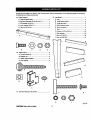
Check all loose parts from the box with the list below. Use the instructionson the followingpages to assemble.
All fasteners are shownactual size.
15. Leg Stand ........................................................... 1
12. Table Support
A. Table SupportRails ....................................... 2
B. Square head bolt (5/16-18 x 314 in.) .............. 4
A. Leg ................................................................. 4
C. Flat washer (5/16 in,) ..................................... 4
D. Lock washer (5/18 in.) ................................... 4
C. Long top brace ............................................... 2
D. Short bottom brace ........................................ 2
E. Hex nut (5/16-18) ........................................... 4
E, Short top brace .............................................. 2
B. Long bottom brace ......................................... 2
F. Foot ................................................................ 4
G. Screw (1/4-20 x 5/8 in.) ............................... 40
H. Star washer .................................................. 40
I. Hex nut (1/4-20) ............................................ 40
J, Hex nut (3/8-16) .............................................. 8
©©.®
B
C
D
E
13. Table Clamp ....................................................... 2
A. Thumb screw (2) ............................................ 2
B. Square nut ..................................................... 2
C. Table clamp bracket ...................................... 2
D. Cup washer .................................................... 2
o
o
O(
ol
ol
o I
O0
J
B
c
14. Owner's Manual (not shown) ............................. 1
G
H
I
J
Fig. 6C
[IIIIFI_NIIli" RADIALSAW315.220380
14
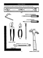
Thefollowing
toolsareneeded
forassembly
andalignment.
Theyarenotincluded
withthissaw.
LEVEL
HEXKEYS:
S/32In.AND1/8in.
MEDIUM FLAT BLADESCREWDRIVER
#2 PHILUPSSCREWDRIVER
PENCIL
SMALL HAMMER
C8
FRAMINGSQUARE
15
Fig. 7
ClUlFt'$MAI1"RADIALSAW315.220380
F
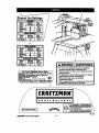
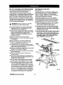
-ontrol CutSettings
Crospcut
D
Wood
Seftlng
Feet
Type
Position Minute
Hard
A
0-6
Medium
B
0-20
Soft
C
0-35
B ,vel Cr0sscJt
Wood
Type
All Types
Setting
Position
A
Feet
Minute
0-6
e
Wood
Type
Hard
I Setting
[ Position
I
A
Mediuml e
Soft
I
Feet
Minute
0-6
0-20
0-35
c
,
c
Compound
Cr0=scot
Wood
i Setting
Feet
Type
I Position
S.IITypes
A
WARNING/ ADVERTENCIA
Minute
0-6
• For your own safety, Read and understand
owner's manual before operating saw.
• This tool has more than one connection to the
power source.
• To reduce the risk of electrical shock or Injury,
disconnect all power connections
• When sarvlclng, usa only Identical
replacement parts.
• Para au segurldad, lea y entlenda el manual del
propletarlo antes de operar la sierra.
C
10 inch Radial Arm Saw
_'_
600RPM120/ 2410
VOLTS
1316.6'Aml1
6oez ACONLY[
RNING: WHENSERVICING,USEONLYIIDEN'I1CAL |
FTSMANREPLACEMENTPARTS,
ROEBUCKANDCO,
I
/
]
wl
J
sterner Help Line 1-800-932-3188/
Fig. 8A
(HFT_;NRIrRADIAL
SAW316,220_10
16
Control
Cu_t
H
On I
Ofre
i
'
_
F
H._
& WARNING
i_._,.
ADVERTENClA
F_pw sahd,/,
read0Nm maualbeta.op_'_q
J" "War_
hqOlu.
f
r-
:rr'.e'ock
1
/
J
i
• Donotpedormfreehandeots.
J • Returncankiga tofull rear psaltisaalter eachcrossrut,
• SeeInotn_lonsoll hawtoreducethe riskM M_.
"men dpplng,use pus_
rosa blade _ sot2 Inchesor moreDin
_nu.
/
• WhimdbPlng,m p_l_
andauxiliary lama whsabladeIssotbotlsa
f
lf2 end2 inchesfromtom:o.Ohnotrake dp aidsnarrewerthan1/2 ioch,
r • Ksap handsoutofpathof btoda,
, OnnotIHch nroungsaw blade.
Turnpower off andwalt to_ bladeto stopbeforemovingworkplaceor
changingsattlnp.
DUnglngsaw beforechangingthe bladeor sarviving,
, Paresasngultdad,len yeotlendael msauotdviproplviado
antesde090mrhi slofla
AWARNING
ADVERTENCIA
• Read and understand owners manual
before operating sew.
• For your safety, do not use
accessories without proper guarding.
• Provide proper workplece support
• Position cutting tool behind the
fence.
• With power off and switch key
removed, turn cutting tool by hand to
make sure it does not strike guard,
fence or any other sew parts.
• Pare su segurlded, lea y entlenda el
manual del propletario antes de
operar is sierra.
Fig. 8B
17
ClUiFl'|HlilrRADIAL
SAW316,320380
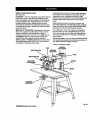
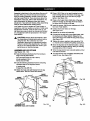
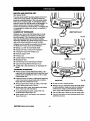
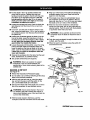
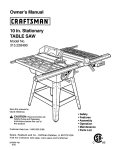
KNOWYOURRADIALSAW
See Figure 9A.
OVERVIEW -The main operating componentsinclude
the column, the arm, and the yoke assembly (yoke,
motor, and blade), and their operation is summarized
in the paragraph below. Safety features and control
functionsare given also. Spending a few minutes
reviewingthe illustrationsand features list below and
on the followingpages to locate these items will make
assembly easier.
METHOD OF OPERATION: The column at the back
of the saw supportsthe radial arm. The arm can be
raised or lowered to change the blade height or
swiveled left and rightfor a miter cut. A yoke fits into
a Carriage on the arm, which can travel back and
forward. The yoke supportsthe yoke assembly
(motor, blade, and blade guard) and can be pivoted
so the blade faces right,front, or left. The motorcan
be rotatedto change the blade angle.
Control functions include 1) column height (elevating
handwheel), 2) arm angle (arm lock knob), 3) yoke
movement on arm (*carriage lock knob) 4) yoke
rotation(*yoke pivot latch and *yoke lock handle), and
5) blade bevel (*bevel index lever and *bevel lock
knob).
Safety features includethe controlcut device, the
removable switch key, and the blade guard assembly.
Never operate the saw without ensudngthese safety
features are in place and functioning correctly.
On a radial saw, =cross cut" means a cut parallel to
the arm, and a "ripcut' is perpendicularto the arm.
There are several ways to make cuts, dependingon
the size and material of the workpiece and the end
resultdesired.
Beforeattempting to use your saw, familiarize yoursaff
with all operating features and safety requirementsof
your Sears Craftsman Radial Arm Saw.
*Shown on following pages
CONTROL
CUTHOUSING
YOKE
ARMLOCKKNOB
CARRIAGE
ANDCOVER
SWITCHANDKEY
COLUMN
BLADEAND
BLADEGUARD
MOTOR
ELEVA_NG
HANDWHEEL
Fig. 9A
[IIIIF'Ir$MRW
RADIAL
SAW31S.220380
18
FEATURESLIST
See Figures 9A-9D.
ADJUSTABLE TABLES - A narrow spacer table and
wider rear table that can be repositionedor even
replaced with different tables. See Figure 9C.
ANTI-KICKBACK PAWLS - Toothed pawls that snag
the work in case of kickbackduring ripcuts. (When
the blade is parallel to the arm, the pawls are in front
of the blade.) Keep the pawls in place to reduce risk
of injury. See Figure 9D.
ARM - The assembly extendingfrom the column,
whichsupportsthe yoke, the motor, and the blade.
See Figure 9A.
ARM LOCK KNOB - Controlsarm angle. Use to set
the arm to the positive stops at 0", 45" left, and 45"
right and to lock the arm in place. Located on top of
arm at front. See Figures 9A and gB.
BEVEL INDEX KNOB - Controls the blade angle
between positive stops at 0", 45", and 90". Located
behind the handle. See Figure gB.
BEVEL INDEX SCALE - Shows the blade angle for
bevel cuts and is located behind the handle. See
Figure 9B.
BEVEL LOCK LEVER - Sets and locks blade angle. It
is located below the handle. See Figure 9B.
BLADE - For maximum performance, use the Craftsman 40-tooth, 10 in. carbide-tipped blade provided
with your saw. It is a high-qualitycombination blade
suitablefor rippingand crosscutoperations. Blades
recommendedfor other operations are listed in the
Accessorysectionof this manual. The blade is
powered by the main motor and turned off by the
switch. See Figure 9D.
_,
WARNING: Use only blades rated for at least
5,000 rpm and recommendedfor use on this
saw. Check with your nearest Sears retailstore.
BLADE GUARD ASSEMBLY - Protective unitover
the blade, with a rivingknife, anti-kickback pawls, an
upper blade guard, a lowerouter blade guard, and a
lower inner blade guard. Always keep each item in
place unlessspecificallyinstructedto move it. See
Figures 9A and 9D.
BLADE GUARD CLAMP SCREW - Secures the
blade guard to the motor. Located between the blade
and the motor. See Figure 9D.
MITERSCALE
YOKEPIVOTLATCH
ARMLOCKKNOB
RIP
SCALE(S)
YOKE
COLUMNTUBE
YOKE
LOCKHANDLE
BEVEL
INDEXKNOB
BEVEL
INDEXSCALE
COLUMNSUPPORT
ER
MOTOR
19
CARRIAGE
- Shdes
alongtrackunderarmand
supportsyoke. Contained in two carriage covers, one
on each side of the arm. See Figure 9C.
CARRIAGE LOCK KNOB - Controlswhether the
carriage is locked or can travel Located on the left
side of the arm on the carnage cover. See Figure 9C.
COLUMN - Updght housingat the back of the saw,
consistingof a column supportand a column tube.
The column tube can be raised or lowered with the
elevating handwheel at the frontof the saw See
Figures 9A and 9B.
FENCE - Removable guide for work, which extends
across w_dthof table, See Figure 9C.
FRONT TABLE - Fixed portionof the worktable that
supportsthe work. See Figure 9C.
CONTROL CUT DEVICE - Limitscarriage speed to
prevent climb, using a cable from the cardage to the
column. Has a separate motoron left side, which is
activated by the switch triggerin the handle. The
cable returns the carriage to the column when the
motoris not activated. Speed is adjusted with a
thumbwheel on the handle. It runs on a separate
120V AC single voltage circuit See Figure 9C.
_i,
DUAL VOLTAGE - If needed, your main power
source may be rewired by a qualified electdcianto
providea 240V AC circuit. See the Electricalsection.
DUST GUIDE - Directssawdust, created from the cut
being made, in the directionyou set. Located at the
rear of the upper blade guard. See Figure 9D.
ELEVATING HANDWHEEL - The handwheel below
the worktable (in front)that changes the heightof the
arm and the blade. See Figure 9C.
HANDLE - Used to pull the yoke assembly. Mounted
on the yoke to the right of the blade. See Figure 9C.
HOLD DOWN - A metal guard to control workpiece
climbdudng ripcuts. When blade parallelsarm, hold
down is over the back of the blade. See Figure 9D.
HOLD DOWN KNOB - Controls placement of the hold
down and locks it m place. See Figure 9D.
WARNING: When connecting onlyone of'the
cords, squeeze the switch tdgger in the handle. If
the mare motorcord alone is connected, the
switchtrigger in the handle will not operate the
controlcut device. The carriage cannot be
advanced without power to the controlcut device.
TRACK
MITER SCALE - Shows the miter angle settingof the
arm. See Figure 9B.
CARRIAGE
LOCKKNOB
CARRIAGE
ANDCOVER
CONTROL
CUTMOTOR
SWITCH
ANDKEY
CONTROL
CUTCABLE
CONTROLCUT
THUMBWHEEL
REAR
TABLE
FRONTTABLE
SPACER
TABLE
ELEVATING
HANDWHEEL
FENCE
Fig. gC
qtlIIRSNRWRADIAL
SAW315.2L_B0
20
MOTOR
(13/6.5AMP)- Powers
thebladeandis
controlled
bytheswitchand key at the frontof the
arm. The powerful inductionmotorhas a capacitor
start. It is mounted in the yoke and rotatedwith the
bevel index knob and bevel lock lever. See Figure 9B.
RIP SCALES - Show the distancefrom the fence to
the blade. (In-dp scales are on the right side of the
arm, and out-ripscales are on the left side.) Upper
scales show the distance with the fence beside the
fronttable. Lower scales show the distancewith the
fence in farthest back position. See Figure 9B.
RIVING KNIFE OR SPREADER - Located directlyin
front of the blade and beside the anti-kickbackpawls,
the rivingknife keeps cut edges from bindingduring
rip cuts, See Figure 9D.
RIVING KNIFE BRACKET - Allows adjustment of the
dving knife. Located midway along the rivingknife.
See Figure 9D.
RIVING KNIFE KNOB - Adjusts the rivingknife and
locks beth the pawls and the rivingknife in place.
Located toward the top and front of the blade guard. '
See Figure 9D.
SWITCH TRIGGER - Used to power the controlcut
device to allow yoke assembly to be pulledforward.
Mounted in the handle. See Figure 9D.
SWITCH WITH KEY - Powers the blade motor.
Placed on the front of the arm for easy access. To
lock the switch once it has been pressed to OFF,
remove the yellow key. Place the key in a locationthat
is inaccessibleto childrenand others not qualifiedto
use the tool. See Figures 9A and 9C.
YOKE - Supportsthe blade and motor. Can be
pivoted to index the blade between rip and crosscuts.
Located between the carriage and the motor. See
Figure 9B.
YOKE PIVOT LATCH - indexes the yoke (after it is
released) to positionthe blade to face right (out-rip
cut), front (cross cut), or left (in-rip cut). Located on
the right cardage cover. See Figure 9B.
YOKE LOCK HANDLE - Releases the yoke to allow
indexingfor ripcut or cross cut. Located belowthe
yoke, on the right. See Figure 9B.
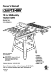
DUSTGUIDE
HOLD DOWN
SWITCH
HOLD
DOWNKNOB
RIVING
RIVINGKNIFE
UPPER
BLADEGUARD :
o
RIVING
KNIFEBRACKET
LOWER
BLADEGUARD
ANTI-KICKBACK
BLADE
__
21
Fig. 9D
rlUIFTSNIIW
RADIAL
SAWStl;_mSO
Assembly is best done in the area where the saw will
be used. When you remove the saw and hardware
from the packing matedals, carefullycheck the items
with the Loose Parts list. If you are unsure about the
descriptionof any part, refer to their illustrations.For
your convenience, all fasteners have been drawn
actual size. If any pads are missing,delay assembling
untilyou have obtained the missingpart(s).
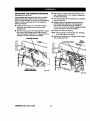
•
Place a 3/8-16 hex nut on each levelingfoot and
insert levelingfeet intothe bottom of the legs. Cap
with remaining3/8-16 hex nuts but only finger
tighten. See Figure 10,4.
•
Place a short upper brace inside twoof the legs
(wide end of legs up) and align the three holes in
the brace with the holes in the legs.
• Insertthe screws. Add the star washers and 1/4-20
hex nuts. Fingertighten.
Your radial arm saw is capable of a wide variety of
operations,and thus requiresa number of initialsetup
adjustments.However, once the saw is set up, you
can check yoursaw in about ten minutesand correct
any misalignmentwith the proceduresin the Adjustment section.
•
Installa shortlower brace on the legs.
See Figure I OA.
• Repeat for the otherend assembly.
• Connect the leg sets with a long upper brace. Add
the hardware and finger tighten.Repeat for the
other side brace, then installthe long lowerbraces.
See Figure lOB.
• Tighten all screws, washers, and nuts with a 7/16
in. wrench and as needed a #2 phillipsscrewdriver.
CAUTION: Perform all the proceduresin both
the Assemblyand Adjustmentssectionsbefore
using the saw. Run a check on your saw
frequently, referringto the Adjustmentssection.
Failure to performthe adjustmentsin the initial
set up or on a frequent basis can result in poor
performanceor machine damage.
•
Move the leg stand to the desired location.Using a
level, adjustthe levelingfeet by raisingor lowering
the bolts with a 9/16 in. wrench.
ASSEMBLING
LEG STAND
See Figures 10,4- IOC.
•
When the leg stand is level, securelytighten all four
nuts with the wrench.
• Take the followinghardware from the hardware
bags in the leg stand carton:
•
Your leg stand is now completelyassembled and
ready for use. See Figure 10C.
40 truss head screws(1/4-20 x 5/8 in.)
40 star washers (1/4 in.)
40 hex nuts (1/4-20)
•
LONG
UPPERBRACE
Take the followinghardware from the remaining
hardware bags in the leg stand carton:
4 levelingfeet
8 large hex nuts (3/8-16)
•
Obtain four legs and eightbraces from the leg
stand carton. See the Loose Parts section.
SHORT
SHORT
LOWERBRACE
LONG
LOWERBRACE
Fig. lOB
;TAR
WASHER
HEADSCREW
HEXNUT
(1_-20)
HEXNUT
(3/8-16)
I.EVEUNGFOOT
I:RIIR3MIIWRADIAL
SAW315.220380
Fig. 10A
Fig. 10C
22
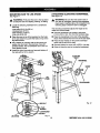
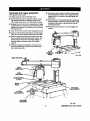
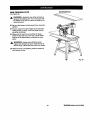
MOUNTING
SAW TO LEG STAND
See Figure 11.
An'ACHING
ELEVATING
See Figure 12.
,_
_1= WARNING: Be sure the main power cord of
your saw is unplugged.Ignodngthis precaution
could resultin serious injury. Do not performthe
followingsteps unlessthe saw is unplugged.
•
WARNING: Firmly bolt the saw to the leg stand
to keep the saw from tipping,walking,or sliding.
Locate the followinghardware from a small hardware bag:
The elevating handwheeladjuststhe heightof the
radial arm and the blade.
4 hex boils (5/16-18 x 5/8 in.)
4 Iockwashers(5/16 in.)
8 flat washers (11/32 in.)
4 hex nuts (5/16-18)
• Place the saw on top of the leg stand so the holes
in the saw base line up with the holeson top of the
leg stand braces.
•
•
HANDWHEEL
•
Take the handwheel, star washer, and screw
(10-24 x 5/8 in. Soc. Hd.) from the hardware bag.
•
Place the bandwheel on the end of the elevating
shaft, which extendsfrom the front of the saw base.
•
Place the star washer on the screw and thread
screw intothe end of the shaft.
Put a washer on a screw, and put the screw and
washer intothe hole in the saw base. Cap with
another washer, then a Iockwasherand a hex nut.
Hand tightenthe set.
• Securely tightenthe screwwith a 5/32 in. hex key.
•
Raise or lowerthe arm by turningthe handwheel.
Installthe otherthree sets and securelytighten all ,
four sets with a 1/2 in. wrench.
ELEVATING
SHAFT
HANDWHEEL
SCREW
SAW
BASE
LEG
_TANO
STARWASHER
SAWBASE
Fig. 12
FLAT
HEX NUT
LEGSTAND
Fig. 11
23
CRRFTJ[MIIW
RADIALSAW315,220380
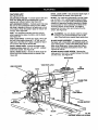
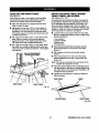
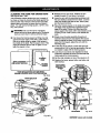
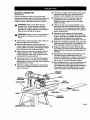
INSTALLING
THE YOKE
See Figures 13A - 13C.
FORCLARITY,CARRIAGECOVERSANDCARRIAGE
LOCK
KNOBARENOTSHOWNIN ILLUSTRATION
ASSEMBLY
The yoke rides in the carriage below the arm and
supportsthe motor, the blade guard, and the blade.
Install the yoke assembly from the front of the arm.
• Remove the carriage stop screwand Iockwasher
from belowthe frontof the arm with a 1/4 in. hex
key. See Figure 13A.
ARMLOCKKNOB
BEARINGS
(4)
CARRIAGE
ARMVIEWEDFROMBELOW
YOKE
_CARRIAGE
•
STOPSCREW
1/4In.HEXKEY
Fig. 13A
Remove the arm cap screws and arm cap from the
frontof the arm with a phillipsscrewdriver, See
Figure 13B.
CARRIAGE
LOCKKNOB
ARM
ARMLOCKKNOB
ARMCAP
ARM
CAPSCREWS
CARRIAGE
COVER
Fig. 13C
Fig. 13B
•
Remove and discard the two motorsetscrewsin
the bottomof the motor. They are for shipping
purposesonly.
•
Using the elevating handwheel, raise the arm 3
inches and remove the packing material.
•
Lock the arm with the arm lock knob, located on top
of the front of the arm, so the arm doesn't swing
while you are mountingthe yoke assembly.
•
Pick up the yoke assembly and carefully slipit onto
the carriage track below the arm. Keep it parallel
with the arm so bearingsslide in smoothly,See
Figure 13C.
[Rlllrl3MIIIr RADIALSAW316_20380
•
Reinstallthe cardage stop screw, the Iockwasher,
arm cap, and arm cap screws, Tighten all screws
securely.
_IL WARNING: Once the yoke assembly is on the
carriage track, reinstallthe arm cap, the arm cap
screws, the carriage stop screw, and the
Iockwasher.Do not riskserious injuryor damage
to the saw by failing to replace these parts.
•
24
Tighten the carriage lock knob, on the carriage
cover on the left of the arm, to lock the yoke
assembly in place.
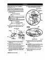
REMOVING
THE BLADE
See Figure 14.
Remove the blade and blade guard assembly during
setup for safety and better access. The blade guard
includesan upper blade guard, an outer lower guard,
and an inner lowerguard. The lower inner guard
consistsof two overlappingslotted metal strips. The
stripsare held together with a retainingscrew and a
nut. Locate these items before beginningthe procedure.
_i,
WARNING: To prevent accidental contact with
the blade that could result in injury,remove the
blade and blade guard before makingsetups
involvingthe blade arbor and work stand. Use
the blade wrenches providedwith your saw.
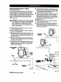
ATTACHING
TABLE
SUPPORTS
See Figure 15.
The table supportsare a base for the three wooden
table sectionsand fence.
•
Locate the two table supportsand the following
hardware:
4
4
4
4
•
square head bolts(5/16-18 x 3/4 in.)
Iockwashers(5/16 in.)
hex nuts (5/16-18)
flat washers (5/16 in.)
Attach the supportsto the side of the saw base.
There are holes in bothsides of each support.The
long side of each support(withthe slottedholes)
fits against the saw base.
B Use two square head boltsper support,inserted
from withinthe saw base outward.
•
Remove the retainingscrew and nut at the bottom
of the lower inner blade guard.
•
Place a fiat washer, a lock washer, and a hex nut
on the end of each screw.
•
Loosen the guard clamp screw, a long thumbscrew
between the blade guard and the motor.
•
Positiontable supportsso that boltsare approximatelycentered in slottedholes.
•
Rotate and lift the guard assembly up and over the
blade, then remove it.
•
•
Hold the blade arbor (motorshaft) with one of the
two blade wrenches provided.Put the otherblade
wrench on the blade nut and turn it clockwise
(down), since the blade arbor has left hand threads.
Fingertighten or snug with a 1/2 in. wrench onlyat
this time. Final adjustmentswill be made later in
Leveling The Table Supportssection.
•
Remove the blade nut, outer blade washer, saw
blade, and inner blade washer. Set these Items
aside until all the tables have bean installedand the
fronttable is level.
THUMBSCREW
TABLE
SUPPORT
FLAT
WASHER
SQUARE
HEAl)BOLT
BLADE
RETAINING
SCREWANDNUT
TO
LOOSEN
\
BLADENUT
INNERBLADE
WASHER
TABLE
SUPPORT
TO
BLADE
ROTATION
BLADE
WRENCH(2)
BLADE
ARBOR
_'_
Fig, 14
MOUNTTABLESUPPORTS
USINGTHESEHOLELOCATIONS
Fig. 1B
25
rltRFTSNRB"
RADIAL
SAW315.220_I0
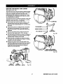
SET'rING THE ARM LOCK KNOB
ARMCAP
MOTOR
See Figure 16.
It may be possibleto move the arm when locked, if
the arm lock knob is too loose• If the arm does not
move freely when unlocked,the arm lock knob may
be too tight. Use this procedure to check and set the
arm lock knob by turningthe arm lock wheel (under
the carriage arm).
•
•
•
YOKELOCK
HANDLE
To release the arm lock knob, located on top of the
arm at the front, pullthe arm lock knob forward until
the spring is compressed.
While holdingthe arm lock knob forward,swing the
arm 30" to the left or the right,referring to the miter
scale on top of the column.
YOKE
ASSEMBLY
Lock the arm in place by pushingthe arm lock knob
back untilit popsin the lockedposition.
Fig. 17A
•
Lockthe yoke lock handle. Grasp the motorwith
both hands and apply reasonablepressureto see if
it slips. If it moves, reset the yoke lock handle as
follows.
• Remove the arm cap screwsand arm cap at the
front of the arm with a phillipsscrewdriver. See
• Release the arm lock knoband turn the lock wheel
Figure 13B.
clockwiseto tighten or countemiockwise to loosen.
• Remove the cardage stop screw and Iockwasher
• Repeat above steps untilthe arm movement is
with a 1/4 in. hex key. Carefullyslidethe yoke
minimizedwhen locked.
assembly forwardand offthe carriage.
•
Place the yoke assembly in a spot where itwill be
ARM
ARMLOCKKNOB
TURNCOUNTERCLOCKsecure as you work on the top of the yoke.
WISETO LOOSEN
• Release the yoke lock handle. Tightenthe center
nut with a 15/16 in. wrench untilthe lock handle is
centered between the two legs of the yoke.
•
Apply a reasonableamount of pressure on the arm.
The arm can be forced but if it moves easily, it
needs adjustment.
• Locate the arm lockwheel.
_,
• Carefully replace the yoke assemblyon the carriage arm track. Slide it back about halfway.
• Replace the cardage stop screw and Iockwasher,
followed by the arm cap and arm cap screws.
•
CARRIAGE
STOPSCREW
ARM
LOCKWHEEL
TURNCLOCKWISE
TOTIGHTEN
Fig. 16
Lockand test the yoke again. If it can be movsd,
repeat the procedure until it is secure.
_
SET'rING
THE YOKE CLAMP
See Figures 17.4and 17B.
YOKELOCK
HANDLE
The yoke clamp keeps the yoke from rotatingon the
carriage when you want the saw blade to be stationary. Use this procedure to check and set the yoke
clamp.
•
•
CENTERNUT
Release the yoke lock handle (below the arm on
the dghtside) so the motorcan be rotated.
Swivel the motorslightly•It should be at an angle in
• between one of the preset positive stop angles.
LEG
Fig. 17B
[lUlFT|NIIIr RADIAL
SAW315.220380
26
SETTING THE
REVEL
LOCK
LEVER
See Figures 18A-18C,
The bevel lock lever locksthe blade at desired angles
other than the preset positivestop angles. The bevel
lock lever is preset at the factory but may need
readjustmentafter shippingor extended use. Check
for overtightnessor looseness and make any necessary adjustmentsas follows:
The bevel lock lever is locatedon the frontof the yoke
assembly, near the bottom. It is attached to a clamp
boltthat controlsthe amount of tightness.
• Pullthe bevel lock lever forwardto unlockit. Use
the bevel index knob (just under the handle) to
rotate the motorapproximately30". Lock the bevel
lock lever.
•
•
STARWASHER
If the bevel lock lever is difficultto lock,the clamp
boll needs to be loosened, if the motorcan be
forced out of position,the clamp boltneeds to be
tightened.
SOCKETSCREW'_'_
I
1/8 In. HEXKEym----_
Remove the socket screw (under the bevel lock
lever) and star washer with a 1/8 in. hex key.
BEVEL
LOCKLEVER
Fig. 18B
• Use the bevel lock handle as a wrenchto tightenor
loosenthe clamp bolt. The clamp belt has a righthanded thread. Tighten it leftto right.
• When the boltis correctlyset, remove the bevel
lock lever from the clamp boil and place it roughly
parallel to the yoke assembly.
• Replace the socket screw and star washer, Recheck the tightnessof the bevel lock lever. Repeat
the steps above untilthe motoris secure when
locked, and the bevel lock lever fitssquarely
againstthe yoke assembly.
BEVELLOCKLEVERIN
CORRECTLOCKEDPOSITION
Fig, 18C
BEVEL
BEVEL
LOCKLEVER INDEXKNOB MOTOR
Fig. 18A
27
(RIIFT_[NAN"RADIALSAW315,220380
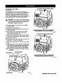
TIGHTENING
THE
ARM AND COLUMN
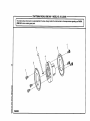
ADJUSTING
THE COLUMN
TUBE
See Figure 19.
See Figures 20A - 20D.
There should be no play, vertical or horizontal,in the
arm relativeto the column. If you can movethe arm
up, down or sideways when the arm lock is unlocked,
use the followingsteps to tighten the arm,
The purpos¢.pfthis procedureis to check whether the
inner column tube is snug in the housingand to
remove any looseness. Loosenesscould resultin a
poor cut or difficultyin elevatingthe carriage. The
column tube is the upper portionof the column and
extends from the columnsupport,
Note: The arm shouldpivot onlywhen the arm lock
knob is unlockedand pulled forwardto compress the spdng.
•
Using a phillipsscrewdriver, remove the rear cover
screws (2) and rear cover from the backof the arm.
This uncoversthe boltson the column.
•
Tighten the top two bolts evenly untilthe arm is firm
and there is no vertical or horizontalmovement.
•
Also check the two bottomhex nuts. It is not
necessary to tighten them as tight as the upper
bolts. Howeverthey shouldbe tightenedeven and
snug.
Note: It is crftica/to remove all loosenesswith this
procedure. If this procedureis not done correctly,followingadjustmentswill be wrong and
could resultin machine damage.
This procedure checks both the elevating action and
the rotatingaction. If a check does not show looseness, do not performthe adjustment.
• Replace the rear cover and rear cover screws.
• Tighten screws securely.
REAR
COVERSCREWS
•
If the arm is not at O"(straightfonNard), release the
arm lock knob, set the arm, and re-lockthe arm
lock knob.
•
Elevation check:To check the elevationmovement,
place your hand under the frontof the radial arm.
Press upward on the radial arm. There should be
no play between the column tube and the column
support.The whole assembly shouldmove as one.
See Figure 20A.
COLUMN
TUBE
REAR
COVER
ARM
HEXBOLT(2)
COLUMN
SUPPORT
Fig. 20A
HE](NUT(2)
(lUlF1]MIIW RADIALSAW316.220380
Fig. 19
28
•
ElevationAdjustment
Rotationcheck:To check the rotation, hold the front
of the ann with one hand and grasp the top of the
column supportwith the other. Press the arm to the
side. If there is play between the column support
and the column tube, it needs to be adjusted. See
Figure 20B.
COLUMN
COLUMNTUBE
COLUMN
SILVER
COLUMNSUPPORT
•
BLACK
SCREWS
Fig, 20B
Elevation Adjustment:If the elevation check did not
show any play between the column tube and the
support, go to the rotationadjustment.Otherwise,
raise and lowerthe ann with the elevatinghandwheel. Tighten the black screws on the right side of
the column supportby 1/16th to 1/8th of a turn.
Tightenthe two silver screws on the left side
slightlymore. You will need two 1/2 in.wrenches or
sockets. Turn the elevating handwhselagain. If the
column tube binds, loosenthe silverand black
screws and tum the handwheelagain. ?SeeFigure
20C.
• When the elevation is smooth,check for looseness
again by pressingupward on the front of the arm.
Repeat the previousstep untilelevation is smooth
with no play between the columntube and the
column support.
Fig. 20C
•
RotationAdjustment:Using a 3/16 in. bax key,
slightlytighten the two cap screwsat the back of
the column support(left side) until no play shows
between the radialarm and the column. The cap
screws are indicatedby arrows. See Figure20D.
• Recheck the rotationby holdingthe frontof the
arm, grasping the top of the columnsupportwith
the other, and pressingthe ann to the side.
RotationAdjustment
CAP
SCREWS
29
Fig. 2OD
CIIIIFTSNAI('
RADIAL
RAW$1S.,_
ADJUSTING
THE CARRIAGE
See Figures21A and 215.
•
BEARINGS
Loose carriage bearings permitthe blade to wander
slightlywhile cutting,which will resultin a poor cut
and more wear and tear on the saw. Use the following
steps to check for tightness and to then adjust the
beadngs if needed.
• Turn the eccentricscrew a partialturn as needed to
tightenthe bearing.
• Retighten the nut and repeat the second stepto
test the tightness.Adjust if so the bearingturns
even against resistancewhen the carriage is
moved - but not so much that the carriage is difficult
to move and retum it to its rear position.
• Repeat for the left rear bearing.
• On the leftside of the arm, remove the carriage
lock knob, the carriage cover screws, and the
carriage cover.
•
Use a 9/16 in. wrenchto hold the eccentricscrew
(top of beadng) and a 1/2 in. wrench to loosen the
nut belowthe bearing.
With one hand, grip the front bearinghard to keep it
still, and pull the carriage forwardwith the other
hand. The beadng shouldturn. If it stays stillas the
carriage is moved, it needs to be adjusted.
Note: Adjust bearingson the leftside only. Bearings
on the right side do not adjust.
•
CARRIAGEBEARING
Replace the carriage cover, carriage cover screws,
and carriage lock knob.
ECCENTRIC
SCREW
GRASPANDHOLD
CARRIAGEBEARING
Fig. 21A
9/16In.
WRENCH
WRENCH
Fig. 21B
I;RIIFTSNIIN"RADIALSAW315.220380
30
LEVELING
THE TABLE
See Figures 22,4 and 22B.
SUPPORTS
Place the wrench belowthe shaft and checkthat
the clearance is the same. If not, adjustthe table
supportuntil it is the same, Securelytightenthe
frontscrew,
The table supports must be perfectlylevel.
• Pull the bevel lock lever forward to unlockit. Use
the bevel index knobto rotate the motorso the
arbor shaft pointsdown. Lock the bevel lock lever.
•
Release the arm lock knob to angle the arm. Begin
by positioningthe arbor shaft over the back of the
highesttable support. Normallythis is the left side.
See Figure 22,4.
•
Lock the arm lock knob and the cardage lock knob.
•
Using one of the blade wrenchesas a feeler gage,
place it on the table supportbelow the arbor shaft.
•
Move the arm to the oppositeside and repeat the
above procedure.When the oppositeside is level,
recheck the first side to make sure that it is still
accurate and even.
•
Return the saw and motorto normal height and
position.
• With the elevating handwheel, carefullylower the
motor untilthe shaftjust touchesthe wrench.The
wrenchshould move with only slight resistance.
Securelytighten the back screw on the table
support.
i
Withoutchangingthe elevation, move the arm to
place the blade arbor over the frontof table support. See Figure 22B.
'
BLADE
WRENCHAT
FRONT
Fig. 22B
BEVEL
INDEXKNOB
BEVEL
LOCKLEVER
BLADEWRENCH
AT BACK
BLADE
ARBOR
RIGHTSIDE
TABLESUPPORT
LEFTSIDE
TABLESUPPORT
ELEVATING
HANDWHEEL
Fig. 22A
31
[IIRFTSHRII"RADIALSAW315.220380
INSTALLING
THE FRONT
See Figures 23,4 - 23C.
TABLE
U-CLIP
AUGNU-CLIP
OVERTHISHOLE
Use this procedure to installthe fixed fronttable.
The top of the table has counterboredholes, preddlled
from the top, around the center to attach the table. In
the center are a counterbored hole and a small hole,
which is not counterbored.They are used for raising
or loweringthe center of the table until it is level.
•
•
Locate the fronttable and the followinghardware:
1 tee nut
1 U-clip (1/4 in.)
1 setscrew (1/4-20 x 7/8 in.)
4 pan head screws (1/4-20 x 1 in.)
1 pan head screw (1/4-20 x 1-3/4 in.)
5 fiat washers (5/8 in.)
4 lock washers (1/4 in.)
4 hex nuts (1/4-20)
Place the fronttable on a solid worksurfoce,with
the top surface face down. Place the tee nut in the
non-counterboredhole and tap it in place with •
hammer.
Fig, 23B
B Place the long pan head screw intothe center hole
and thread into the U-clip. Do not tighten untilthe
table has been chockedfor evenness. See Figure
23,4.
SETSCREW
1.3/4In.SCREW
FLAT
WASHER
•
Place the setscrewthroughthe small levelinghole
end thread intothe tee nut, but do not tighten.
•
Put a 1 in. long pan head screw in the four remaining holes end throughthe holes in the support.
Cap with • lock washer end hex nut, Tighten with a
7/16 in. wrench and phillipsscrewdriver.This
completesinstallationof the front table.
SETSCREW
1-3/4In.SCREW
l
TEE
NUT
SCREwlln"
_1
REAROFFRONTTABLE
I°_
,
I
FLAT
WASHER
Fig. 23A
•
Snap the U-clip onto the front edge of the saw
base. Line up the hole in the U-clip with the saw
base hole just to the leftof the center notchin saw
base. See Figure 23B.
•
Place the table, top up, on the table supportsso the
center counterboredhole linesup over the hole in
the U-clip.
Place a flat washer in each counterboredhole.
•
;
I
HEXNUT
LOCKWASHER
Fig. 23C
[ERFTSMRW
RADIAL
SAW315.220380
32
LEVELING THE FRONTTABLE
INSTALLING
REAR TABLE, SPACER
TABLE, FENCE, AND CLAMPS
See Figures25A - 25C.
The placement of the tables and fence may need to
be changed for different cuts, depending on the size
of the workpiece and the positionof the blade. The
fence shouldbe installednext to the front table for
maximum depth capacity; it shouldbe installed in the
middle for maximumcross cut capacity;and installed
all the way back for maximum rip capacity.
See Figure24.
If there are any high or low areas on the front table,
they should be removed by adjustingthe leveling
screws in the center holes on the front table.
•
Place the rear table on its edge across the front
table to check for gaps.
• Adjust gaps of less than 1/32 in. in the center of
the table by tuming the setscrewwith a fiat blade
screwdriveruntil the setscrewtouches the frame.
Then lightlysecure the center pan head screw with
a phillipsscrewdriver.
•
•
•
For a gap of more than 1/32 in. in the center of the
table, raise the center by turningthe setscrew
against the frame. Then lightlysecure the center
pan head screw with a phillipsscrewdriver.
2
2
2
2
For a gap of more than 1/32 in. on the sides, lower
the center of the table by tighteningthe center pan
head screw with a phillipsscrewdriver.Then tighten
the setscrew.
PHILLIPS
SCREWDRIVER
_ll
Locate the fence, the spacer table, the rear table,
and two unassembledclamps,which consistof the
following hardware:
ONPANREADSCREW
_%
SETSCREW
cup washers
clamp brackets
square nuts
thumbscrews
•
Place the fence behindthe fronttable, then the
spacer table behindit, and then the rear table
behind it.
•
Slip a square nut intothe slot of each clamp
bracket.
•
bracket
fromthe slot.Thread
it into
the
Place a farthest
thumbscrewintothe
end of the
clamp
enut
Note: If the screw is inserted in the wrong end of the
bracket,the clamp will not work.
•
Place the clamp bracket intothe rectangle holes in
rear table and turn the thumbscrewclockwiseuntil
it snaps intothe cup washer,
• Tighten the thumbscrewsto clamp the table sections into place.
___
the
REARTABLE
table support.Held the cup washer
FENCE
against the
REARTABLE
FRONTTABLE Fig 24
SPACERTABLE
FRONTTABLE
Fig. 25A
33
[RRFTSNRWRADIALSAW315.220380
INSTALLING
BLADE AND BLADE GUARD
See Figures26,4 and 26B.
• Collect the blade and hardware that were removed
eadier. Place the inner bladewasher, saw blade,
outer blade washer, and blade nut on the blade
arbor. See Figure26A. Note: The concave side of
blade washers go againstthe blade.
• Hold the blade arbor with one wrenchand rotate
the other blade wrenchcounterclockwise(up), to
tightenthe blade nut. See Figure26B. Note: Blade
arbor has left hand threads. Test the blade to make
sure it turnsfreely,
THUMBSCREW
CLAMP
BRACKET
•
SQUARENUT
I
CUP
WASHER
CLAMPSHOWN
ASSEMBLED
SLOT
F .25B
• Attach the blade guard over the blade sothe riving
knife and pawls face front. See Figure26A.
• Tilt the guard approximately45 ° down in the front,
place it over the blade, and rotate it to a horizontal
locked position.
•
RECTANGLE
HOLE
Use the bevel index knob(above the handle) and
the bevel lock lever (below the handle)to set and
lockthe motorat 0". The blade will be vertical.
Retightanthe blade guard clamp screw, the long
thumbscrewlocatedbetween the blade guard and
the motor.
• Check that the guard is firmly seated in the groove
on the motorhousing.
• Tighten the guard clamp screw.
•
Replace the retainingscrew and nut at the bottom
of the lower inner blade guard.
THUMBSCREW
BLADE
TABLE
SUPPORT
TO
LOOSEN
RET_NING
SCREWANDNUT
CUP
WASHER
RIVINGKNIFE
ANDPAWLS
TO
TIGHTEN
BLADENUT
INNERBLADE
WASHER
Fig. 26A
TO
SCREW
BLADE
ROTATION
TO
BLADE
WRENCH(2)
BLADE
Fig. 25C
Fig. 26B
(IIRFT|MIIW
RADIAL SAW 315.220380
34
ALIGN RIVING KNIFE TO BLADE
• With the elevating handwheel, lowerthe arm until
the blade just clears the table.
See Figures 27A - 27C.
When rippingthe rivingknife must be cantered with
the blade to ride in the middle of the kerf and keep it
from binding. Bindingpinchesthe blade. Blade
pinchingcan cause kickback.
There are two pairs of anti-kickbackpawls.
_l
WARNING: Failure to use the rivingknife, hold
downs, and anti-kickbackpawls can allow
kickback. Kickbackcan throw the workpiece
toward the operator, resultingin serious injury.
• Put the bladeto the in-rippositionby first loosening
the yoke lock handle, below the carriage on the
right. Then pull the yoke pivot latch (rightside of
arm, on carriage) forwardand rotate the yoke to the
left. This indexesthe yoke 90 ° so the blade is
between the motor and the column. Lockthe yoke
lock handle.
• Supportthe lower outer blade guard and loosenthe
carriage lock knobon the left of the arm. Move the
yoke back untilthe blade touchesthe fence. Reset
the carriage lookknob.
•
Loosenthe rivingknife knob, at the frontof the
upper blade guard. Lowerthe rivingknife to the
table and tightenthe knob. if the knife restsagainst
the fence, with one set of pawls ridingon the fence,
no adjustment is needed.
• If the rivingknife is on the fence or not touchingit,
loosenthe rivingknife slottednut (justabove the
pawls,to the right).Correct the rivingknife position
and retightenthe cap nut.
CARRIAGE
LOCKKNOB
%
YOKELOCKHANDLE
RIVINGKNIFE
KNOB
RIVINGKNIFE
m
(
LOWEROUTER
BLADEGUARD
RIVINGKNIFETOO
FARRIGHTOFFENCE
RIVINGKNIFE
BLADEGUARD
ANDBLADE
ANTI-KICKPAWLS
FRONTTABLE
I
Fig. 27A
FENCE
CORRECTALIGNMENT
OFTHERIVINGKNIFE
ANDANTI-KICKPAWLS
Fig. 27C
RIVINGKNIFEONTOPOFFENCE
TOOFARLEFTOFBLADE
Fig. 27B
35
rlIIIFTSMRW
RADIAL
SAW315,220380
INSTALLING RIP SCALE INDICATORS
SCREWS
See Figure 28.
RIPSCALE
INDICATOR
The ripscale indicatorson the arm show the distance
between the blade and the ripfence with the fence in
the front and rear positions.The upper scale is used
when the fence is positioneddirectly behindthe front
table. The lower scale is used when the fence is at the
extreme rear, directly in front of the column.
SPEEDNUT
CARRIAGE
The In-Rip Indicator is on the dght side of the arm.
The Out-Rip Indicatoris on the left side of the arm.
•
Remove the followingfrom a small hardware bag.
_'_SPRING
2 ripscale indicators
4 screws
2 speed nuts
• On the left of the radial arm saw, remove the
carriage lock knob and spdng.
•
CARRIAGE
LOCKKNOB
• Insert a speed nut inside the carriage cover with the
fiat side up. Place the scale indicatoron top of the
cardage cover and attach with two screws. Securely tighten screws.
Replace the cardage cover and tightenthe carriage
cover screws.
•
Replace carriage lock knob and spring.
•
Repeat for the right side.
The final step will be connecting the controlcut
device. The controlcut device offers many benefits.
As it increasesoperator control, it eliminatesthe risk
in a cross cut of the saw "climbing" Outand over the
workpiece at the operator. Feed controlof the blade
as it cutsthrough the workpiece increases, as does
the accuracy of the cut. The followingadjustments
need to be completed before the controlcut device is
connected.
Your radial arm saw is designedto perform a variety of
complex cuts with fine tolerances. A weekly alignment
check ensuresthatyoursaw can performwithprecision.
It takes about ten minutes and the results is better
performanceand a longer life for your saw.
_k
Perform the checks in the order given. If you miss an
adjustment, go back to the missed adjustment and
repeat all steps from that point forward.
CRIIFTSHAM'
RADIALSAW315.220380
Fig. 28
To complete settingup your saw, continue with the
Adjustmentprocedures. The adjustmentsshouldbe
checked regulady, dependingon usage. Your saw will
provideaccurate cuts with fine tolerancesas long as
you protectthe accuracy with frequent alignment
checks. The radial arm saw can performa wide range
of high quality cuts.
Remove the two carriage cover screws and the
carriage cover.
•
SCREWS
36
CAUTION:
Failure to check alignments and_
perform the adjustmentsin the initialset up or on
a frequent basis can resultin poor performanceor
machinedamage.
ALIGNING
THE
ARM FOR CROSS
Release the arm lock knob. Positionthe arm
straightforward (O') and leave it unlocked.
CUTS
See Figures 29A - 29C.
This procedure checks whether the arm is exactly O"
for cross cut travel by checking the blade against the
table and the miter indicator.Remove the rear table,
spacer table, and fence, but leave the front table in
place. You will need a framing square, a 3/16 in. hex
key, and a pencil.
Lowerthe arm with the elevatinghandwheel until
the saw bladejust clears the front table. Lockthe
yoke lock handle (rightside of saw, belowyoke)
and the bevel lock lever.
•
_lb WARNING: Be sure the saw is unplugged
before performingthese adjustments.Accidental
start-up could resultin serious personalinjury.
• First check the framing square by fittingone side
against the back edge of the table. Lightlydrew a
line on the table along the edge of the square in
the middle of the table. Flip the square over. If the
edge stillmatches the line with no gaps or overlaps, the square is true.
Place the framing square on the table and position
one edge of the square firmly againstthe back
edge of the table. Positionthe other leg of the
square against the blade until it rests beside but not
touchinga tooth. With a pencil, mark besidethis
tooth.
• Slowly move the yoke assembly forward and
backwardalong the arm and againstthe square
without rotatingthe blade. If the mark moves intoor
away from the square, adjust the arm with the
followingsteps.
• At the back of the column, loosenthe three setscrewswith a 3/16 in. hex key and positionthe arm
as needed to align with the framingsquare.
• Lock the arm lock knob and retightenthe three
setscrews. Recheck the cross out travel with the
blade againstthe framing square.
• Set the miter indicatoron top of the columnto 0".
•
DRAWA STRAIGHT
..."UNE ALONGTHISEDGE
FRAMING
SQUARE
Replace the fence, spacer table, rear table, and
table clamps.
REARCOVER
REMOVED
FOR
CLARITY
THERESHOULDBENOGAPHEREWHEN
SQUAREIS FUPPEDOVERTO DOTTED,
posmoN
Fig. 29 A
MITERINDICATOR
ARM
LOCKKNOB
SETSCREWS
YOKE
HANDLE
FRAMING
SQUARE
SETSCREWS
ELEVATING
HANDWHEEL
Fig. 29 C
Fig. 29 B
37
rRIIFTtNIIN" RADIALSAW315,220380
ALIGNING
BLADE
TO TABLE
AT O" BEVEL
•
If there are no gaps, fullytighteneach screw, If
there is stilla gap, repeat the previoustwo steps.
This procedure squares the blade to the table at O"
bevel (vertical) so the blade angle willbe accurate. If
the blade is not at D"bevel, follow the steps below to
rotate slightly.You willneed a framing square and a
1/4 in. hex key.
• Positionthe blade in front of the fence. Lowerthe
blade with the elevating handwheeluntil it just
clears the fronttable.
•
Check the bevel indicatoron the yoke assembly
near the handle. It should read O'. If itdoes not,
reset it by looseningthe screws and rotatingthe
bevel indexcap. Retightenthe two screws.
Loosen the cardage lock knob.
See Figures 30A - 30D.
•
•
BLADESQUARETOTABLE
Lock the followingcontrols:
bevel lock lever belowthe handle,
carriage lock knob on the leftside,
arm lock knob on top of the arm, and
yoke lock handle below the yoke, on the dght.
•
Stand a framing square on the table with the short
leg pointingup againstthe saw blade and the long
leg parallelto the fence. Place the squareflat
against the blade between two teeth.
•
If both the top and bottomof the saw blade a_reflat
againstthe square, no adjustment is needed.
•
If the saw blade gaps at the top or bottom, remove
the bevel indexcap by removingthe two phillips
head screws (below the handle). You willsee four
sockethead screws.
•
Loosen the socket head screwswith a 1/4 in. hex
key. Rotate the motorslightlywhile holdingthe
square againstthe saw blade and table top.
•
Slightlytighten each of the four screws and recheck
the blade and framing square.
NO ADJUSTMENTNEEDED
FRAMING
SQUARE
TABLEj
Fig. 30 B
FRAMING
SQUARE
GAP
BLADE
ARMLOCKKNOB
BLADE
GAP- ADJUSTMENT
NEEDED
Fig. 30 C
INDEX CAP
BEVELINDEX
CAPREMOVED
f
BEVEL
LOCK
LEVER
FRONTTABLE
ELEVATING
HANDWHEEL
SOCKET
HEADSCREWS
Fig. 30 A
_. BEVEL
LOCKLEVER
Fig. 30 D
CRAFTSMIIH"
RADIAL
SAW315.220380
38
SQUARINGBLADE TO FENCE
•
Release the yoke lock handle (below the yoke on
the fight). With a 1/2 in. wrench, slightlyloosen the
two hex bolts holdingthe yoke pivotlatch.
•
•
Rotate yoke assembly untilthe gap is eliminated.
Lock the yoke lock handle. Retightenthe two hex
boltson the yoke pivotlatch.
See Figures 31A - 31C.
This procedure squares the miter angle of the blade to
the fence to reducethe dsk of bindingand kickback. If
the blade is not square to the fence, the yoke assembly must be rotated slightly. Have a framing square, a
1/2 in. wrench, and a phillipsscrewdriverat hand. The
blade shouldbe lowered to just clear the table.
Release the carriage lock knob.
_k
•
• Replace the carriage cover.
• Loosen the carriage lock knob and guide the yoke
assembly to the back of the arm.
SAWVIEWED
FROMABOVE
WARNING: The blade must be angled at 90" to
the fence when the handle is at the frontof the
saw. If not, kickbackcould resultduring a cross
cut. Kickbackcan cause serious injuryby throwing the workpiece toward the operator. In addition, a faulty miter angle on the blade can splinter
or bum the cut edges of the workpiece dudng
cross cutsor dp cuts.
BLADE
GAPADJUSTMENT
NEEDED
Use the arm lock knobto index and lockthe arm in
0" miter position (straightforward).
.,
Pullthe yoke assemblyforward to the front of the
arm. Lock the carriage lock knob.
• Place the shortend of the framing square against
the fence. Rotate the square to 45 ° to the table.
Place the long edge across the flat surface of the
blade, belowthe center of the blade. (Do not place
the edge against a tooth.)
• Check whetherthe blade isflat against the edge for
the entire lengthor whether a gap is visible.
BLADE
•
•
I
NOADJUSTMENT
NEEDEDI
If the blade needs adjustment,remove the rightside
carriage cover with a phillipsscrewddver.
ARMLOCKKNOB
FRAMING
SQUARE
BLADE
FENCE
GAPADJUSTMENT
NEEDED
Fig. 31 B
FENCE
HEXBOLTS
FRAMINGSQUARE
Fig. 31 A
YOKELOCKHANDLE
Fig. 31 C
39
(RRFT|MRW RADIALSAW$1S_20380
PARALLELING
BLADE
See Figures 32A-32C.
TO TABLE
• Check whetherthe blade is flat againstthe edge
the entire length or whethera gap is visible. If you
can see a gap, adjustthe blade to be at 90" bevel
to the table with the followingsteps.
• Unlockthe bevel lock lever. Loosenthe rear motor
mountnut,which holdsthe motoron the yoke.
Place a fiat blade screwdriverin one of the slots,
and rotatethe cam behind the nut to eliminate the
gap between the blade and the square.
This procedure squares the blade to the table at 90"
bevel so hodzontat cuts will be accurate. This also
reduces kickback,as well as splintedngand burning
of the cut edges of the workpiece. If the blade is not at
90' bevel, follow the steps to rotate the blade unit
slightly.You will need a framing square and a flat
blade screwdriver.
,_
• Retightenthe nut.
• Tighten the bevel rockfever. Recheck the blade
and the square for any gaps.
WARN|NG: The blade must be pedactly parallel
to the table at the 90" reading on the bevel scale.
If not, kickbackcould result, as well as splinteringor burningthe cut. Kickbackcan result in
serious personalinjuryas the workpiecacan be
thrown at the operator.
•
Use the arm lock knobto lock the arm in O"miter
position (straightforward).
•
Turn the elevating handwheelto raise the blade at
least 2 in. above the table.
',
•
Release the bevel lock lever belowthe handle. Use
the bevel indexknob, just under the handle, to turn
the motor to 90". The blade willbe hodzontal. Lock
the bevel lock lever.
Raise the bladewith the elevating handwheelto
approximatelyhalfway up. Index the blade to a
vertical0" bevel with the bevel index knob. Lock it
with the bevel lock lever.
ADJUSTMENT GAP
NEEDED
•
Place the framing square with the shortend hanging down in front of the worktable and the long side
on edge under the blade.
• Lower the arm with the elevating handwheelso the
blade surface restson the square. Turn the blade
slightlyif necessary so the face of the blade, not a
tooth, tieson the square.
NOADJUSTMENT
NEEDED
Fig. 32 B
BEVEL
LOCK
FENCE
BLADE
FRONTTABLE
FRAMING
SQUARE
o
Fig. 32 A
Fig. 32 C
CRIIFTSNIIIr RADIALSAW315,220380
40
ALIGNING
THE
RIP SCAL•
INDICATORS
• On the rightside of the arm, check the lower in-dp
scale indicator,whichshould be set on O inches. If
it is not, loosenthe screws and shift the indicator
untilit reads zero. Tightenthe screws.
See Figures 33A - 33B.
The rip scale indicatorson the arm show the distance
between the blade and the rip fence. The upper scale
is used when the fence is positioneddirectly behind
the front table. The lower scale is used when the
fence is at the extreme roar, directly in front of the
column.
The in-rip indicatorand scale are on the right side of
the arm. The out-rip indicatorand scale are on the left
side.
• Turn the blade to the in-rip positionby loosening
the yoke lock handle, below the arm on the right.
Then pull the yoke pivotlatch forward and rotate
the yoke to the in-ripposition.This indexes the
yoke 90" so the blade is between the motor and
the column. Lock the yoke lock handle.
With the elevating handwheel, lowerthe arm until
the blade just clears the table.
•
Loosen the carriage lock knoband guide the blade
beck to just touchthe fence. Tightenthe carriage
lock knob.
•
Lay the framing square on the table with the short
edge against the fence and with the long side
toward the table front.
On the left side of the arm on the out-dp scale,
check the rip scale indicatoron the rear fence
position(lowerscale). The rip scale indicatorshould
mark the same number as the distancemeasured
from the fence to the blade. If it does not, loosen
the screws and shiftthe scale untilthe indicatoris
correct.Tighten the screws.
If the fence is not at the rear of the tables, place it
there.
•
Loosenthe yoke lock handle. Pull the yoke pivot
latch forward and rotate the yoke to the out-rip
position.The blade shouldbe in front of (outside)
the motorand the column.
Note the distancewhere the blade contactsthe
framing square.
This procedure checksthe indicatorswith the fence at
the back of the tables directlyin front of the column.
The blade shouldbe turned to the in-dp positionto set
the rip scale indicatoron the dght side of the arm.
Then, the blade should be turned to the out-dp
positionto set the rip scale indicatoron the left side of
the arm. You will need a framing square.
•
•
OUT-RIPSCALEONLEFTSIDEOFARM
RIP.SCALEINDICATOR
10.
,,,..,°=.,11
Front Fence Position
Rear Fence Position
IN-RIPSCALEONRIGHTSlOEOF_,RM
RIP-SCALE
INDICATOR
Saw
II
CARRIAGELOCK KNOB
Fig. 33 B
11,,, °,,,,,,,,
• .,d!
A
,_
.d!
.__
YOKEPIVOTLATCH
Fig. 33 A
41
[IIliFTtMitN" RADIALSAW315.220380
INSTALLING
See Figure 34.
CONTROL
CUT
DEVICE
• Plug in the control cut cord, leaving the main power
cord disconnected.Squeeze the switchtdgger to
confirmthe control cut motoris receivingpower.
Note: Before installingthe controlcut device, the yoke
assembly will travel beck and forward on the
carriage by pullingthe handle. After installing
the control cut device, the power cordfor the
control cut device must be plugged in and
switchtrigger pressed to move the yoke
assembly and carriage on the arm.
• On the left side of the saw, remove the carriage
lock knoband spring. Remove the two screwsthat
attach the carriage cover and remove the cover.
,_= WARNING: Do not install the controlcut device
untilafter all of the initialadjustmentsand
alignments are made to prevent accidental
startingof the saw that could result in serious
personal injury.
The controlcut device offers many benefits. As it
increases operatorcontrol, it eliminates the risk in a
cross cut of the saw "climbing"out and over the
workpiece at the operator. Feed controlof the blade
as it cutsthrough the workpiece increases, as does
the accuracy of the cut.
The controlcut cable maintains a steady pull on the
cardage assembly from the column.This tension
keeps the assembly at the column, unlessyou
squeeze the switch triggerin the handle. The switch
tdgger activatesthe motorto counter the pull of the
cable.
•
Replace the spdng and carriage lock knob. Pullthe
cardage assemblyabout halfway t0 the front.
Tighten the carriage lock knob.
•
Squeeze the switchtrigger in the handle with your
dght hand and pullthe springloaded cable from the
columnwith your left hand. If you preferto use a
pair of pliers,do not damage the cable. Note: Do
not to let the spdng loaded cable clamp slipout of
yourhand or pliers.If it slipspast the cable bracket
and goes up intothe control cut motorhousing,
then disassemblyof the controlcut assembly willbe
requiredto get it beck out.
•
Place the barrel fittingintothe socketat the back of
the carriage assembly.
•
Remove the carriage lock knoband spring. Replace
the cardage cover and screws, then replacethe
springand carriage lock knob.
• Set the speed thumhwheel, usingthe chart on the
label. If you are unsureof the properspeed setting,
use the lowest setting.
After a cut is completed, press the switch on the arm
off, then release the switch tdgger to preventfurther
forward motion. Hold the handle untilthe blade has
stopped rotating.The yoke assembly will not roll
forward unlessyou are squeezing _e switch trigger.
The controlcut powercord is designedto operate on
a single voltage AC circuit.The speed can be set with
a thumbwheel on top of the handle. The three speed
settingsare describedon the label locatedon the left
side of the control cut housing.
BARREL
FIITING
CARRIAGE
ASSEMBLY
WARNING: Do not use the saw withoutthe
control cut and blade guards in place unless
specificallyinstructedto do so. Otherwise
uncontrolledcontactwith the blade could occur,
resultingin personal injury.
,_
WARNING: Take great care when workingwith
either cord to ensure you have the correct one. If
you Intend to unplug the main power cord but
remove the control cut cord Instead, the
blade could be accidentally started and cause
Injury.
SOCKET
CIIAFrSHlUFRADIALSAW315.220380
42
Fig. 34
BASIC OPERATION
ARM SAW
OF THE
RADIAL
A radial arm saw can be used for straight-linecutting
operations such as cross cutting,ripping, mitering,
beveling, compound cutting,and resawing. It can
make dado or molding cuts with special attachments.
This sew is designed to cut wood and wood composition productsonly.
The three-prong plug must be plugged into a matching outletthat is properly installedand grounded
accordingto all local codes and ordinances. Improper
connectionof the equipmentcan result in electric
shook. Check with an electricianor service personnel
ifyou are unsure about propergrounding. Do not
modifythe plug; if it will not fit the outlet, have the
correctoutlet installedby a qualified electrician.Refer
to the Electrical page of this manual.
TYPES
OF CUTS
See Figure 35.
The radial sew makes cross cuts parallel with the arm'
(across the grain), and rip cuts square to the arm (with
the grain). Each can be made with the blade vertical
or beveled. Instructionsfor makingeach kind of cut
are given later in this section.
RIP CUTS
In dp cuts, the yoke is rotated 90" left or rightand
locked in place. The wood must ride firmlyagainst the
rip fence. There are two orientationsof ripcuts - the
in-rip and the out-rip. The in-rip positionprovides
better visibility.Out-rip cutscan also be made with the
blade beveled.
In an in-ripcut, the yoke is rotatedto the left, which
puts the blade in between the column and the motor.
The wood is fed from the right hand side.
In an out-ripcut, the blade is in front of the motor, and
the wood is fed from the left. Out-rip cuttingis recommended only when the blade is set 12 in. or more
from the fence.
_1= WARNING: Always make sure the blade guard
and anti-kickbackpawls are in place and working
propedy when making ripcuts to avoid possible
injury.
WARNING: Always use a pushstickwith small
pieces of wood, and also to finish the cut when
rippinga long narrow piece of wood, to prevent
your hands from getting close to the blade.
A
WARNING: All blades and cutting accessories
am, must be rated for at least 5,000 rpm to prevent
possible injury.
0
_
_CROSS
cu'r
CROSSCUTS
®
Cross cuts are made parallel to the arm. The blade is
pulledalong the length of the radial arm ,withthe wood
secured.
There are several types of cross cuts. A cross cut
shows 0"on the miter scale (arm straight)and 0" on
the bevel scale (blade straight).A miter cut is made
with the radial arm angled and the blade straight.A
bevel cut is produced with the arm straightand the
blade angled.
A final type of cross cut is the compound cross cut.
Both the arm and the blade are angled. Be thoroughly
familiar with making cress cuts, bevel cuts, and miter
cuts before trying a compound miter cut.
Note: in cross cuts, the blade teeth point down as
they strike the wood. In rip cuts, the teeth point
up as they strikethe wood.
_
(_)
MITERcur
_'_BEVEL
CUT
COMPOUND
CROSSCUT
O
WARNING: NEVER make a cross cut with the
short edge of the wood parallel to the fence. Kick
back is likelyto occur, causing the workpiece to
be thrown back at you. Treat such a workpiece
as a rip cut.
O
__
___BEVEL
RIPCUT
RIPCUT
Fig. 35
43
I:IIRFTSMflN"
RADIALSAW315,220380
SWITCH
AND SWITCH
See Figures 36-38.
KEY
The main power switch has been placed on the front
of the arm for easy access. The yellowswitch key
prevents accidental startingof the main power switch
when saw is not being used. To activate the switch,
insertthe switch key and liftswitch to ON position.To
lookthe switchonce it has been pressed to OFF,
remove the yellow key. Place the key in a locationthat
is inaccessibleto childrenend othersnot qualifiedto
use the tool.
CAUSES
OF KICKBACK
INSERTSWITCHKEY
Kickbackcan occur when the blade stalls or binds,
kickingthe workpiece back toward you with great
force and speed. If your hands are near the blade,
they may be jerked loose and contactthe blade.
Obviously, kickbackcan cause serious injuryand it is
well worth using precautionsto avoid the risks.
Fig. 36
Kickbackcan be caused by any actionthat pinches
the blade in the wood, such as the following:
•
Making a cut with incorrectblade depth
•
Sawing into knotsor nails in the workpiece
• Twistingthe woodwhile makinga cut
•
Failingto supportwork
•
Forcing a cut
•
•
Cuttingwarped or wet lumber
Misusingthe saw
•
Not following correctoperatingprocedures
•
Using the wrong blade for the type of cut
•
Cuttingwith a dull, gummed-up,or improperlyset
blade.
AVOIDING
SWITCHON
Fig. 37
KICKBACK
• Always use the correctblade depth setting.The
outer point of the blade teeth shouldclear the lower
surface of the workpiece by 1/8 in. to 114in. when
making these cuts,
•
•
Inspectthe work for knots or nails before beginning
a cut. Knock out any loose knotswith a hammer.
Never saw intoa loose knotor nail.
SWITCHOFF
•
Always use the fence when ripcutting.This helps
prevent twistingthe wood in the cut.
•
Always use clean, sharp, and properly-setblades.
Never make cuts with dull blades.
•
To avoid pinchingthe blade, supportthe work
properlybefore beginninga cut.
Do not cutwet or warped lumber.
• Always hold yourworkpiecefirmlywith both hands
or with pushsticks.Keep your body in a balanced
positionto be ready to resist kickbackshould it
occur. Never stand directly in line with the blade,
• Use the right type of blade for the cut being made.
• Use the rivingknife and anti-kickbackpawls when
performingripcuts.
• When makinga cut, use steady, even pressure.
Never force cuts.
_EAFTSNlUI"RADIALSAW$15,220380
Fig. 38
44
CUTTING
AIDS
See Figures 39-41.
Cuttingaids are used to improve the setup and help
make the operator's work safer end more accurate.
They can be made from scrap wood and in various
sizes and shapes for specific projects,
The basic types are pushsticks,pushblocks,and
featherboards. If the blade is set 2 in. or more from
the fence, use a pushstick.Use a pushblockwhen the
blade is between 1/2 in. and 2 in. from the fence. (If
the cut is narrower than 1/2 in., use a different saw.)
Refer to the drawings and instructionsprovided so
you san make safer and more precise cuts.
PUSHSTICKS
Fig. 39
PUSHSTICKS
See Figure 39.
Pushsticksmust be narrowerthan the workpiece, with
a 90" notch in one end and shaped for a grip on the
other end.
pos
Loo s
See Figure 40.
A pushblockhas an uprighthandle with a base
attached to the handle. Some pushblockshave a foot
that extends down from the base and againstthe
workpiece.The foot is attached to the base with glue
only to prevent damage to the blade.
FEATHERBOARDS
PUSHBLOCKS
Fig. 40
FEATHERBOARD
Fig. 41
I
See Figure 41.
Featherboardsare used for large panels, along with
an auxiliary table and a C-clamp. A featharboard has
an angled end to fit against the edge of the workplace.
It is clamped in place so the workpiece moves between either the fence and the featherb6hrd or the
table and featherboard. Slots in the end of the
faatharboard help resist kickbackand allow for
variations in the width of the workplace.
Note: The Pushstickdesigns above are for illustration
purposesonly. They have not been drawnto
scale.
_1= WARNING: Clamp the featherboard against the
infeed side of the workpiece. If clamped behind
the blade, it could squeeze the cut edges
together, causing bindingand kickback.Kickback
can cause serious injury.
45
rRAFTSMIIN'RADIALSAW315.220380
MAKING
A CROSS
See Figure 42.
CUT
•
If the blade is angled, raise the plasticlower guard,
release the bevel lock lever, and set the bevel
indicatorto zero. Retightenthe bevel lock lever.
• If the blade is in front of the fence, loosenthe
cardage lock knobon the leftside of the arm.
Release the switchtrigger and let the carriage
returnto the back.
Use this procedure to make a cut with the blade
vertical and straightforward. If a ken`does not exist for
the line of the cut (cutting path), follow the steps to
make one. Each cutting path requiresits own ken`.
_,
WARNING: Make sure the blade guard is
lowered and is workingproperlyto prevent
possibleinjury. Always raise the clear plastic
guard before changingthe bevel or loweringthe
blade to avoid damage to the guard.
,_
WARNING: Keep one hand on the handle until
the blade stops rotatingto preventthe risk of
injury.
H
•
•
•
•
•
Put the fence in the front position(next to the front
table) and tightenthe table clamps.
Check that the controlcut device is set for the
correctspeed for the type of wood and cut you are
planning. Refer to the chart on the label and adjust
the thumbwheelon the handle accordingly.
•
If there is no ken',cut one approximately1/16 in.
deep. Grasp the handle and turn the saw on with
the switch on the arm. Squeeze the switchtrigger
on the handle and pullthe blade forward across the
table to make the kerr.
•
Release the switchtdgger and let the carriage
return to the back. Turn the saw offwith the switch
on the arm but holdthe handle untilthe blade stops
rotating.Adjust the heightwith the elevating
handwheelso the blade will rotatefreely in the ken'.
•
Positionthe workpiece againstthe fence. Place the
pawls and rivingknifeto clear the workpieceor the
fence, whichever is higher, by at least 114inch.
• Grasp the handle with one hand. With the other,
turn the saw on, then hold the workpiece downand
againstthe fence. Keep your hand well away from
the blade.
If the yoke is not in the crosscut positionwith the
blade parallelto the arm, release the yoke lock
handle (rightside, under yoke). Positionthe yoke
correctlywith the yoke pivotlatch.
•
If the arm is too low or too high,first lift the blade
guard if the arm is too low,and turn the elevating
handwheel at the front of the table. Set the bladeto
just clear the ken`or table.
Squeeze the switchtriggeron the handle and pull
the blade throughthe workpiece but only far
enoughto completethe cut. Keep your hand on the
handle, even after the cut has been made and the
saw turned off, untilthe blade stops rotating.
II After completing the cut, move the workpiecoto the
side and turnoff the saw with the switchon the
arm. Release the switchtriggeron the handle and
let the yoke move back behindthe fence. Do not
release the handle untilthe blade stops rotating.
If the arm is angled, release the arm lock knobon
top of the arm, position it straightahead and lock
the arm lock knob.
ARMLOCK
SWITCH
CARRIAGE
LOCKKNOB
BEVEL
CROSSCUT
RIVINGKNIFE
ELEVMING
HANDWHEEL
Fig. 42
13tlIFTSHAW
RADIAL
SAW315.220380
46
MAKING A MITER CUT
•
See Figure 43.
In a miter cut, the blade is verticaland the arm
angled. If a ked does not exist for the cutting path,
make one (instructionsbelow). Each cuttingpath
requires its own kerf.
If the blade is in frontof the fence, loosen the
carriage lock knob on the left side of the arm and
let the carriage move back.
•
If there is no kerf, cut one approximately 1/16 in.
deep. Grasp the handle and turnthe saw on with
the switchon the arm. Squeeze the switchtrigger
on the handle and pullthe blade forward across the
table to make the kerf.
•
Release the switchtriggerand let the carriage
return to the back. Turn the saw off with the switch
on the arm but holdthe handle untilthe blade stops
rotating.Adjustthe height with the elevating
handwheel so the blade will rotatefreely in the kerr.
•
Positionthe workpiece againstthe fence. Place the
pawls and rivingknifeto clear the workplaceor the
fence, whichever is higher, by at least 1/4 inch.
•
Grasp the handle with one hand. With the other,
turnthe saw on, then hold the workpiecedown and
againstthe fence. Keep your hand well away from
the blade.
•
Squeeze the switchtriggerand pull the blade
through the workpiecebut onlyfar enoughto
completethe cut. Keep your hand on the handle,
even after the cut has been made and the saw
turned off, until the blade stops rotating.
WARNING: Make sure the blade guard is
lowered and is working properlyto prevent
possibleinjury. Always raise the clear plastic
guard before changing the bevel or loweringthe
blade to avoid damage to the guard.
_1= WARNING: Keep one hand on the handle until
the blade stops rotatingto preventthe risk of
injury.
•
Put the fence in the front position(nextto the front
table) and tighten the table clamps.
• Check that the controlcut device is sat for the
correct speed for the type of wood and cut you ars
planning. Refer to the chart on the label and adjust
the thumbwheel on the handle accordingly.
•
Ifthe yoke is not in the cross cut positionwith the
blade parallelto the arm, release the yoke lock
handle and position the yoke correctlywith the
yoke pivot latchon the right side of the arm.
• After completingthe cut, move the workpieceto the
side and turnoff the saw with the switchon the
arm. Release the switchtriggerand let the yoke
move back behindthe fence. Do not release the
handle untilthe blade stops rotating.
•
If the arm is too low or too high,first lift the blade
guard if the arm is too low, and turn the elevating
handwheel at the front of the table. Set the blade to
just clear the kerr or table.
•
To set the angle of the arm, release the arm lock
knob on top of the arm. Use the mite_scale above
the column to position the arm to the desired angle,
and lockthe arm lock knob.
ARM
LOCKKNOB
If the blade is angled, raise the plasticlower guard,
release the bevel lock lever, and set the bevel
indicatorto zero. Retightenthe bevel lock lever.
SWITCH
•
MITERSCALE
YOKE
PIVOTLATCH
YOKELOCK
CARRIAGE
BLADEGUARD
INDICATOR
MITERCUT
LOCKLEVER
TABLE
CLAMP
ELEVATING
HANDWHEEL
47
Fig. 43
CRAFTSMAN"
RADIAL
SAW315.220380
MAKING A BEVEL CUT
•
Release the switch triggerand let the carriage
returnto the back, Turn the saw off with the switch
on the arm but hold the handle untilthe blade stops
rotating.Adjustthe height with the elevating
handwheel so the blade will rotate freely in the kerr.
• Positionthe workpieceagainst the fence. Place the
pawls and rivingknife to clear the workpiece or the
fence, whichever is higher, by at least 114inch,
See Figure 44.
This procedure makes a cut with the blade and motor
angled and the arm straight (90" to fence). If there is
no kerf, followthe steps to make one. Try this cut on
scrap wood before cuttingyour workpiece.
_i,
WARNING: Make sure the blade guard is
lowered and is workingproperlyto prevent
possibleinjury. Always raise the clear plastic
guard before changing the bevel or loweringthe
blade to avoid damage to the guard.
,_
WARNING: Keep one hand on the handle until
the blade stops rotatingto preventthe risk of
injury.
• Grasp the handle with one hand, Withthe other
hand, turn the saw on, then hold the workpiece
down and againstthe fence. Keep your hand well
away from the blade.
•
•
Put the fence in the front position(next to the front
table) and tighten the table clamps.
• Check that the controlcut device is set for the
correctspeed for the type of wood and cut you are
planning. Refer to the chart on the label and adjust
the thumbwheelon the handle accordingly.
•
•
•
Squeeze the switchtriggeron the handle and pull
the bladethrough the workplace but only far
enough to completethe cut. Keep yourhand on the
handle, even after the cut has been made and the
saw turned off, untilthe blade stops rotating.
• After completingthe cut, move the workpieceto the
side and turn off the saw with the switchon the
arm. Release the switchtrigger on the handle and
let the blade move back behind the fence. Do not
release the handle untilthe blade stopsrotating.
If the yoke is not in the crosscut positionwith the
blade parallelto the arm, release the yoke lock
handle and positionthe yoke correctly with the yoke
pivotlatch on the rightside of the arm.
VELEDCUT
If the arm is too low or too high, first liftthe blade
guard if the arm is too low, and tum the elevating
handwheelat the front of the table. Set the blade to
just clear the kerr or table.
SWITCH
If the arm is angled, release the arm lock knobon
top of the arm, positionit straightahead and lock
the arm lock knob.
HANDLE
•
RIVING
Note: For a 45" or 90" angle, the bevel index lever will
seat automaticallyat the preset positivestop
positions.For any otherangle, usethe bevel
lock lever.
ELEVATING
HANDWHEEL
If the blade is in frontof the fence, loosenthe
carriage lock knobon the left side of the arm.
Release the switch tdgger on the handle and let the
carriage returnto the back.
• To set the blade angle, first raise the plasticlower
guard. Release the bevel lock lever, and position
the blade with the bevel index lever. Refighten the
bevel lock lever.
•
YOKELOCK
HANDLE
If there is no kerr, cut one approximately1/16 in.
deep. Grasp the handle and turnthe saw on with
the switch on the arm. Squeeze the switchtrigger
on the handleand pullthe blade forward across the
table to make the kert.
Fig. 44
(IIRFrSNRIr RADIALSAW315.220380
48
MAKING
A COMPOUND
See Figure 45.
CROSS
CUI"
In this cut, boththe blade and the arm are angled. Be
familiar with both bevel and miter cuts before making
a compoundcut. Practice on scrap wood.
_1= WARNING: Make sure the blade guard is
lowered and is workingproperlyto prevent
possible injury.Always raise the clear plastic
guard before changing the bevel or loweringthe
blade to avoid damage to the guard.
_k
WARNING: Keep one hand on the handle until
the blade stops rotatingto prevent the risk of
injury.
•
Put the fence in the front position(nextto the front
table) and tightenthe table clamps.
• Check that the controlcut device is set for the
correct speed for the type of woodand cut you are
planning. Refer to the chart on the label and adjust '
the thumbwheelon the handle accordingly.
•
If the yoke is in front of the fence, loosen the
carriage lookknobon the left side of the arm.
Release the switchtriggeron the handle and let the
cardage retum to the back.
•
If there is no kerr, cut one approximately1/16 in.
deep. Grasp the handle. Turn the saw on with the
switchon the arm. Squeeze the switchtriggerand
pull the blade forwardto make the kerr.
•
Release the switchtriggerand let the carriage
return to the back. Turn the saw Offwith the switch
on the arm but holdthe handle untilthe blade stops
rotating.Adjustthe height with the elevating
handwheel so the blade will rotatefreely in the kerf.
•
Positionthe workpiece againstthe fence. Place the
pawls and rivingknife to clear the workpieceor the
fence, whichever is higher, by at least 114inch.
•
Grasp the handle with one hand. With the other
hand, turn the saw on, then hold the workpiece
down and againstthe fence. If necessary, slightly
raise the outer blade guard for clearance. Keep
your hand well away from the blade.
• Squeeze the switchtriggerand pull the blade
throughthe workpiecebut onlyfar enough to
completethe cut. Keep your hand on the handle,
even after the cut has been made and the saw
turned off, until the blade stops rotating.
• If the yoke Is not in the cross cut positionwith the
blade parallelto the arm, release the yoke lock
handle and positionthe yoke correctlywith the yoke
pivot latch on the dghtside of the arm.
•
If the arm is too low or too high, first liftthe blade
guard if the arm is too low,and turn the elevating
handwheal at the front of the table, Set the blade to
just clear the kerf or table.
• After completingthe cut, move the workpieceto the
side and turn off the sew with the switchon the
arm. Release the switchtdgger and letthe yoke
move back behind the fence. Do not release the
handle untilthe blade stops rotating.
• To set the angle of the arm, release the arm look
knob on top of the arm. Usa the miter scale above
the columnto positionit to the desired'angle,and
look the arm look knob.
ARM
• To set the blade angle, first raise the plasticlower
guard. Release the bevel lock lever, and position
the blade with the bevel index lever.
•
SWITCH
YOKE
PIVOTLATCH
YOKELOCK
Retightenthe bevel looklever.
Note: For a 45" or 90" angle, the bevel index lever will
seat automatically at the preset positivestop
positions. For any otherangle, usa the bevel
lock lever.
HANDLE
BEVELLOCK
BEVELED
AND
ELEVA_NG
HANDWHEEL
49
Fig. 45
(RRFT|NRIrRADIAL
SAW315.220380
RIP CUT
HAZARDS
SETTING
UP A RIP CUT
See Figure 46.
AND PRECAUTIONS
Two hazards are specificallyassociated with rip
cutting:ouffeed zone and wrong way feed.
In the outfeed zone (behind the blade), the blade
teeth point down. The slightestcontact while the blade
is still spinningcan snag clothing,jewelry, the workpiece, or even skin, causing serious personal injury.
A precise and safe rip cut requiresa careful set up.
Before setting up for in-rip or out-rip, especiallyfor a
bevel cut, try the workpiece in both placements.
Check for stability,visibility,and control.Test which
will give the best pushstickclearance.
Wrong way feed occurswhen the workpiece contacts
the blade from the outfeed side. It is very hazardous
and willjerk the workpiece violently.You could be cut
if you are holdingthe workpiece.
Instructionsare given for an in-rip cut. At certain
points, the instructionswill vary for a bevel rip cut or
an out-ripprocessand will be enclosed in parentheses (example). Figure 47 shows an out-ripsetup.
_,
Inserta solidfence with no kerfs. Use an auxiliary
fence if the blade will be set only 1/2 in. to 2 in.
from the fence. Tighten the table clamps.
•
If the arm is too low or too high, first liftthe blade
guard if the arm istoo low,and turn the elevating
handwheelat the front of the table. Set the blade to
just clear the kerf or table.
•
Change the blade angle if needed. Raise the plastic
lower guard to keep itfrom jamming, release the
bevel lock lever, and set the bevel indicatorto zero.
(For a bevel rip cut, set the bevel Indicator to
the desired angle.) Test the clearance on the
guard. ReUghtenthe bevel lock lever.
WARNING: Failureto observe any of these
precautionscan result in serious injury.
• The first precaution is, of course, simplyto stay
completely away from the ouffeed zone. Keep
hands away from the outfeed zone.
•
•
Point the anti-kickback pawls away from the blade
teeth to snag a workpiece if the blade grabs..They
shouldbe positionedto rest lightlyon the
workpiece.The flat side of the pawls shouldbe
level and horizontal.
• Set the rivingknife to just clear the table.
• Set the hold down in front of the blade to just clear
the workpiece.
• Start and finish your cut from the infeed side.
•
Push the workpiece past the pawls with pushblocksand pushsticksto finishthe cut.
SWRCH
•
If the bladejams, turn the saw off with the switch
on the arm, remove the yellowkey, and wait for the
blade to fully stop before freeingJt.
• Make sure the blade is parallel to the fence and the
workpiece is not warped or twisted.
•
Make sure no pressure is applied to the workpiece
on the outfeed side.
•
Make sure the blade guard is lowered and is
workingproperly.
IOWN
• Always set up the workpiece so the wider part of
the wood is between the blade and the fence. This
stabilizesthe workpieca better.
•
Do not release the workpiece until it has moved
past the pawls. Keep pushsticksfirmly in place.
•
Use pushsticksand pushblocks,not your hands,
when the trailingedge of the workpiece is within
3 in. of the blade. If the blade is set 2 in. or more
from the fence, use a pushstick.Use a pushblock
and auxiliaryfence when the blade is between 2 in.
and 1/2 in. from the fence. (If the cut is narrower
than 1/2 in., use a different saw.) For large panel
rip cuts, use a featherboard instead of pushblocks
or pushsticks.See the sectionon CuttingAids.
I;RllFTSHItN'RADIALSAW315.220380
HANDWHEEL
INFEEOFOR
IN RIPCUTrlNG
Fig. 46
50
•
Put the blade in the in-rippositionbetween the
motorand the column.Release the yoke look
handle and pivotthe yoke to the left, with the yoke
pivot latch on the right side of the arm. (Use the
out-rip position only for rlpa 12 in. or more in
width; pivot the yoke to the right so the motor
is between the blade and column.)
•
Keep your otherhand on the table and steady the
workpieceagainst the fence. Keep that hand at
least 8 in. from the blade.
•
if the blade cover does not automaticallydsa as
the workpiece movesfrom the infeed to the outfeed side, stop the cut. Turn off the saw and adjust
the blade cover so it rests on the workpiece.
• Loosen the cardage lookknob. Place the blade the
dghtdistancefrom the fence for the cut and lock
the knob.
•
When the end of the workpiece is stillseveral
inches from the blade, pick up the cuttingaid .you
selected earlier. Push the wood with the pushstick
,or pushblockratherthan your hand.
• Cut a kerf. Turn the saw on with the switch on the
arm. Lower the blade about 1/16 in. intothe table to
cut a shallow groove. Turn the sew off and remove
the yellow key.
• Positionthe workpiece againstthe blade, from the
frontof the table. Lowerthe hold-downin frontof
the blade to just clear the workpiece.(For a bevel
rip cut, place the workplece directly under the
guard rather than beside the blade.)
_k
•
Remove the workpiece from the table. Set the push
block,featherboard, or pushsticknearby.
•
Set up table extension(s) and supports.
_i,
Push the wood completelythroughthe blade to the
ouffeed, past the pawls.
• When the work is completed,press the switch off
and remove the key.
• Loosen the pawls and rivingknife.Lower the dving,
knife to the table. Slide the workpiece back and
lower the pawls so that one set rests on the workpiece. Lock the rivingknife and pawls in place. (For
a bevel rip cut, place the workplece under the
lower set of pawls.)
•
WARNING: Use a pushstickas the end of the
workpiece nears the blade to reducethe riskof
injury.
SWITCH
WARNING: Never use a person to support
workpieces. This can cause kickbackand
sedous injury. Never have someone stand at the
outfeed side.
ANTkKICKBACK
PAWLS
MAKING
A RIP CUT
See Figure 47.
•
Review the Hazards and Precautionspage.
•
Do not make a dp cut withoutfollowingall the setup
steps in the previousprocedure.
INFEEDFOR
OUTRIPCUTrlNG
•
After the saw has been set up, insertthe yellow
key, and turnthe saw on with the switchon the
arm. Let the blade buildup to full speed.
• Stand at the infsed side of the blade and out of the
lineof the workpiece, in case kickbackoccurs.
_i
WARNING: Never stand directlyin the line of
cut. Stand to the side to reduce the chance of
injuryshould kickbackoccur. Start and finish the
cut from the infeed side=
BLADE
Fig. 47
/
•
With the hand closestto th_ fence, push the
workpiece under the hold down and intothe blade.
51
CRRFI"$NRN'
RADIAL
SAW315.220380
MAKINGO_HER OUTS
See Figu_s 48 and 49,
,_
WARNING: Make sure the blade guard is
lowered and is workingproperlyto prevent
possibleinjury.
,_
WARNING: Never put your hands within 3 in. of
the blade when it is on.
Variationsfrom the basic cuts includecuttinglong
workpieces and non-throughcuts.
When making one of the following cuts, followthe
instructionsthat apply for the basic cut, dependingon
the position,shape, and size of the wood. Do not
attempt these cuts until you are skilled with the basic
cuts.
CUTTING
LONG
See Figure 48.
•
•
WORKPIECES
Make sure the wood does not touchthe blade
before you turn on the saw with the switch on the
arm. Let the blade buildup to full speed before it
contacts the wood.
• When the work is completed,press the switch off
and remove the key.
Place a supportthe same height as the saw table
nearby for the cut work.
SUPPORTLONGWORKPIECES
Fig. 48
rltmFT_iNRIrRADIALSAW31S._'0380
52
NON-THROUGH
See Figure 49.
CUTS
NON-THROUGH
CUT
,_L WARNING: Unplug the saw while removingor
replacing the blade guard. Turn on the saw with
the switch on the arm to confirmthe blade is not
receivingpower.
•
Place a supportthe same height as the saw table
nearby for the cut work. Lower the blade with the
elevating handwheel.
•
Make sure the wood is not touchingthe blade.
Insert the key and turn on the saw. Let the blade
build
up to
before
worksection).Rem°ve
thefullspeed
blade and
bladecontactingthe
guard (see Assembly
piece.
•
___
WARNING: Always use pushblockswhen
--'-- making non-throughrip cuts to avoid the risk of
serious injury. Never feed wood with your hand=
i,
•
k
\
When the work is completed, press the switchoff
and remove the key,
Fig. 49
53
rRIIFTSMRWRADIALSAW316.220380
CiENERAL
MAINTENANCE
MOTOI_IELEGTIIIlCAL
•
_i,
_k
•
WARNING: When servicing, use only identical
Craftsman replacement parts. Use of any other
part may create e hazard or cause product
damage.
_k
WARNING: To prevent accidental startingthat
could cause possible sedous personal injury,turn
offthe saw with the switch on the arm, remove
the switch key, and unplugthe saw before
workingon the radial saw.
•
Remove sawdust from and clean the blade guards
frequently.
• Clean plastic parts with a softdamp cloth. Do not
use any strong solvents.
_b, WARNING: Do not at any time let brake fluids,
gasoline, petroleum-basedproducts, penetrating
oils, etc. contact plasticparts. They contain
chemicals that can damage, weaken or destroy
plastic.
Check teeth of anti-kickbackpawls; sharpen with
file if needed.
•
Regularly check all nuts,bolts, screws, and cables
for tightnessand condition.
CRIIFTSNnN'RADIALSAW315220380
WARNING: If the power cords are wom, cut, or
damaged in any way, have them replaced
immediately by a qualifiedservice technicianat a
Sears store or repair center. Failure to do so
could resultin sedous personalinjury.
_IL WARNING; To avoid fire or electrocution,
reassembleelectric parts only with identical
Craftsman replacement pads. Reassemble
exactlyas originallyassembled.
Remove sawdust from the work area, including
inside the blade cover, frequently.
•
Frequentlyvacuum or blow out any sawdust from
the work areas.
54
PROBLEM
Saw does not start.
CAUSE
SOLUTION
I. Motor cord or control-cutcord is
not plugged in.
I. Plug in cord.
2. Cord or switch is damaged.
2. Have the cord or switch replaced at your nearest Sears
Service Center.
3. Circuitfuse is blown.
3. Replace circuitfuse.
4, Circuit breaker is tripped.
4. Reset circuit breaker.
5. Switch is burned out.
5. Have the switch replaced and
requesta voltagecheck from
the power company.
6. Connectionsare loose, burned
out, or damaged.
6, Have the wiring checked and
repaired. Request voltagecheck
from power company.
Lf
Motor does not reach full speed or
power.
Motor stalls, blowsfuses, or trips
circuit breakers.
Motor overheats.
1. Voltage from source is low.
1_ Requesta voltage check from
the power company.
2. Circuitis overloaded with other
appliancesor motors.
2. Test without any other motors
and on differentcircuit.
3. Motor windingsare burned out.
3. Have the windingsreplaced and
requesta voltage check from
the power company.
4, Fuses or circuitbreakers are
wrong size,
4. Have an electricianreplace with
a 15 amp fuse or circuitbreaker.
5. Extensioncord is too long.
5. Use a shorter cord.
6. Starter switch is defective.
6. Have the switch replaced.
1. Starter switch is defective.
1. Have the switch replaced.
2, Voltage from source is low.
2. Requesta voltage check from
the power company.
3. Fuses or circuitbreakers are
wrong size or defective.
3. Have an electricianreplace with
a 15 amp fuse or circuitbreaker.
1. Motor is ovedoaded.
1. Requesta voltage check from
the power company.
2. Windings are burned out.
2. Have the windings replaced and
requesta voltage check from
the power company.
3. Work is being fed too fast.
3. Feed work slower.
55
CRAFTSNAW RADIAL SAW 315.220380
PROBLEM
CAUSE
Saw vibmtas excessively.
I. Blade is warped.
1, Replace the blade. See the
removalprocedure in Assembly
section,
2. Saw is not mounted securely,
2, Tighten all hardware.
3. Work surface is uneven.
3. Reposition on a flat surface.
Adjust the leveling feet on legs.
Saw is noisy when running.
1. Motor needs attention.
1. Have the motor checked at
your nearest Sears Service
Center.
Carriage does not travel smoothly
in track under arm.
1. Track is dirtyor sticky.
1. Clean track. See Installing
Carriage Assemblyin Assembly section.
2. Carriage beadngs are bad.
2. Replace cerdage bearings.
Contact your nearest Sears
service center.
3. Blade or teeth are dull or bent.
3. Sharpen or replace the blade.
See the removal procedure in
Assemblysection.
4. Blade is out of alignment.
4. Use blade alignmentprocedures in Adjustmentsection.
5. Board is warped.
5. Replace the board,
1. Blade or teeth are dull or bent.
1. Sharpen or replace the blade.
See the removalprocedure in
Assembly section.
2. Fence is not straight.
2. Check with square; sand or
replace.
3. Work is being fed too fast.
3. Feed work into blade slower.
4. Wrong blade is being used.
4. Change the blade.
5. Column tube is too loose in the
column support.
5. See Adjustingthe Column
Tube in Assembly section.
6. Arm is misaligned or loose.
6. See Setting the Arm Look
Wheel in the Assembly section.
7. Yoke is loose on carriage.
7, See Setting the Yoke Clamp
procedure in Assemblysection,
8. Sawdust has accumulated
between tables.
8. Remove and clean tables.
Saw stalls when dpping.
I:HFt'$NIUr
RADIALSAW315.220380
SOLUTION
56
PROBLEM
CAUSE
SOLUTION
Handwheel is hard to turn or
column binds,
I. Sawdust has collected on the
elevating shaft,
I. Remove handwheel;clean end
lubricatethe shaft.
2, Columnis out of alignment.
2. See Adjustingthe Column
Tube in Assemblysection.
1. Columntube is too loose in the
column support,
1. See Adjustingthe Column
Tube in Assemblysection,
2. Blade or teeth are bent or dull.
2. Sharpen or replacethe blade.
See the removal procedure in
Assemblysection.
3. Blade is out of alignment.
3. Use blade alignment procedures in Adjustmentsection.
4. Wrong blade is being used.
4. Change blade. See the removal
procedure in Assemblysection.
5, Board is warped.
5. Replace the board.
6. Arm is loose or miseligned.
6. See Settingthe Arm Lock
Wheel in the Assembly section.
7. Yoke is loose on carriage.
7. See Setting the Yoke Clamp
procedure in Assemblysection.
8. Arm is out of alignment,
8. See AligningArm for Cross
Cuts in Adjustmentssection.
9. Work Is being fed too fast.
9. Feed work into blade slower.
1. Bevel lock lever is loose,
1. See Setting the Bevel Lock
Lever in Assembly section.
2. Blade is not perpendicularto
table top.
2. See Aligningthe Blade to the
Table in Adjustmentssection.
3. Columntube is too loose in the
column support.
3. See Adjustingthe Column
Tube in Assemblysection.
4. Table top is not paraUelto the
arm.
4. See Leveling Table Supports
and Leveling the Front Table in
the Assembly section,
5, Yoke is loose on carriage,
5, See Setting the Yoke Clamp
procedure in Assemblysection.
6. Arm is out of alignment.
6. See AligningArm for Cross
Cuts in Adjustmentssection.
Saw burns or scores edges of
wood in cut.
Bevel cuts are not true.
57
CRAFTSHIIN'
RADIAL
SAW315.220380
PROBLEM
CAUSE
SOLUTION
Miter or cross cuts are not true,
1. Scale pointeris not correct.
1. Reset the pointerat the top
rear of arm.
2. Column is out of alignment.
2. See Adjustingthe Column
Tube in Assemblysection.
3. Carriage is misaligned.
3. See Setting the Arm Lock
Wheel in the Assembly section.
4. Yoke is loose on carriage.
4. See Setting the Yoke Clamp
procedure in Assemblysection.
5. Arm is out of alignment.
5. See AligningArm for Cross
Cuts in Adjustmentssection.
6. Sawdust has collected between
tables.
6. Remove and clean tables.
,t
7. Table top is not parallel to the
arm.
7. See Leveling Table Supports
and Leveling the Front Table in
the Assemblysection.
8. Fence/tables are not straight.
8. Check with square; sand or
replace.
1. Blade is not para!lel with fence.
1. See Squaring the Blade to the
Fence procedure in the Adjustments section.
2. Arm is not perpendicularto
fence.
2. See Aligning the Arm for Cross
Cuts procedure in the Adjustments section.
3. Riving knife needs adjustment.
3. See Aligning the RivingKnife to
the Blade procedure in the
Adjustmentssection,
1. Table is not parallel to arm.
1. See Leveling Table Supports
and Leveling the Front Table in
the Assembly section.
2. Column tube is loose in column
support.
2. See Adjustingthe Column
Tube in Assembly section.
3. Arm is loose or misaligned.
3. See Setting the Arm Lock
Wheel in the Assembly section.
Riving knife strikes wood during a
cut.
1. Riving knife not aligned with
blade,
1. See Aligning the Riving Knife to
the Blade procedure in the
Adjustments section.
rlIRFTSNRIr RADIALSAW315.220380
58
Wood edges away from fence
when ripping.
Depth of cut varies from one end
of wood to the other.
PROBLEM
CAUSE
SOLUTION
i
Saw blade tends to push wood to
one side when cross cutting,
1. Blade is heeling.
1, See Squaring the Blade to the
Fence in Adjustmentssection,
2. Column tube is loose in column
support.
2, See Adjustingthe Column
Tube in Assembly section.
3, Arm is loose or misaligned,
3. See Setting the Arm Lock
Wheel in the Assemblysection,
4, Fence/tables are not straight,
4. Check with square; sand or
replace.
5. Blade or teeth are bent or dull.
5, Sharpen or replace the blade.
See the removal procedurein
Assembly section.
illm
59
CRnFTSNnN"
RADMLSAW315.220380
CRAFTSMAN
RADIAL ARM SAW - MODEL NO, 315.220380
=
SAW number
or whenwillbe
ordering
repair
I ARM
The model
found
on parts.
a plate attachedto the base. Always mentionthe model number in all correspondence regardingyour RADIAL
29
31
22
18
19 13
12
22
SEERGUREI
0
SEER
36
37
38
!
31
4O
RGUREA
39
SEEFIGURESFANDG
J
|
CRAFTSMAN
RADIAL ARM SAW - MODEL NO. 315.220380
SAW numberwill
or when ordering
repair
I ARM
be model
be found
on parts.
a plate attached to the base. Always mention the model number in all correspondenceregardingyour RADIAL
J
I
f
PARTS LIST FOR FIGURE A
KEY
NO.
=_.
11r
ro_
€4R
i
PART
NUMBER
1
2
3
4
5
976830-001
974999-002
980528-001
980667-001
976793-001
6
7
980669-001
976786-001
8
9
10
11
12
976834-002
606066-006
989001-002
610122-005
976342-001
13
14
15
16
17
18
19
20
21
22
703776-098
976392-001
967917-001
990908-009
976384-001
641700-006
621380-007
976328-001
624282-003
981043-001
23
24
980530-001
980534-001
25
976829-001
KEY
NO.
PART
NUMBER
LowerArm Cover ........................................ 1
26
641700.005
* Screw (10-16 x 618 in. Pan Hd.) ................. 4
Feed ControlLabel (For Cross Cuts) ......... 1
Cord Label (ControlCut Power Cord) ........ 1
Control Cut Power Cord ............................. 1
Cord Label (Motor Power Cord) ................. I
Motor Power Cord ...................................... 1
* Bolt (3/8-16 x 2-114 in. Sq. Hd.) ................. 2
* Screw (10-32 x 3/8 in. Pan Hd.) ................. 1
Cable Clamp............................................... 2
* Screw (8-32 x 3/8 in. Pan Hd. T. C.) ........... 4
Arm Beadng ............................................... 2
Washer ....................................................... 4
* Lock Nut (3/8-16) ........................................ 2
Cord Clamp ................................................ 2
* Screw (6-19 x 518 in. Pan Hd.) ................... 4
Rear Cover ................................................. 1
* Screw (10-32 x 3/8 in. Pan Hd.) ........ ;........ 3
* Screw (3/8-16 x 2-1/8 in. Hex Hd. Locldng).. 2
Arm Cover Pad ........................................... 1
Square Nut (3/8-16) .................................... 2
Warning Label ............................................ 2
Feed Control Label (For Bevel Cuts) ......... 1
ControlCut Warning., ................................. 1
Upper Arm Cover........................................ 1
27
28
29
30
31
32
33
34
35
36
37
38
39
40
41
42
43
44
45
46
47
48
49
50
976344-001
976354-001
980532-001
980447-001
641700-008
976327-001
980550-001
976393-001
980697-001
980540-001
980542-001
980544-001
976331-001
980546-001
976863-001
622210-042
976862-002
703473-042
977471-001
969220-005
976368-001
60T/37-005
642409-002
976369-001
DESCRIPTION
QUAN.
* Standard Hardware Item -- May Be Purchased Locally
** Available From Div. 98 -- Source 980.00
DESCRIPTION
QUAN.
* Screw (10-32 x 1/2 in. Pan Hd.) ................. 2
Miter Cap .................................................... 1
Miter Indicator............................................. 1
Miter Scale Label........................................ 1
Strain Relief ................................................ 2
* Screw (10-32 x 3/8 in. Pan Hd.) ................. 4
Arm Cover .................................................. 1
Guard Label ................................................ 1
GuardAssembly ......................................... 1
Guard Warning Label ................................. 1
Miter Lock Label (Left Side) ....................... 1
Miter Lock Label (Right Side) ..................... 1
Warning Label (Right Side) ........................ 1
Arm Cap ..................................................... 1
Warning Label (Left Side) ........................... 1
Switch Key .................................................. 2
* Screw (8-32 x 3/8 in. Pan Hd.) ................... 1
Switch ......................................................... 1
Lock Washer ............................................... 1
Tag .............................................................. 1
* Screw (5/16-18 x 3/8 in. Socket Hd.) ......... 1
Cord Clamp ................................................ 1
* Screw (1/4-20 x 1/2 in. Pan Hd.) ................ 1
* Screw (10-16 x 41/64 in. Pan Hd.) ............. 4
Cable Bracket............................................. 1
CRAFTSMAN RADIAL ARM SAW- MODEL NO. 315.220380
[
I
The model number willbe found on a plate attached to the base. Always mention the modelnumher in all correspondence regardingyour RADIAL ARM SAW or when ordering repair parts.
9
|
I
SEE FIGL
32
SEE FIGURE C
FIGUREB
62
I:RAFTSMRN"
RADIAL
SAW31S.220_80
CRAFTSMAN
I
RADIAL ARM SAW - MODEL NO. 315.220380
I
ber
all correspondence
RADIAL
ARM
SAW
or when
orderingrepair
parts.numThein
model
number will be regardingyour
found on a plate
attached
to the
base,
Always
mentionthe model
I
PARTS LIST FOR FIGURE B
KEY
NO.
PART
NUMBER
1
607406-001
2
703473-042
3
624088-002
4
976698-001
5
931275-028
6
703473-042
7
607406-001
8
976339-001
DESCRIPTION
QUAN.
* Hex Nut (5/16-18) .......................................................................... 4
Lock Washer .................................................................................. 4
Washer ........................................................................................... 8
Table Support ................................................................................. 2
Washer ........................................................................................... 4
Lock Washer .................................................................................. 4
* Hex Nut (5/16-18) ..........................................................................
Clamp Bracket ...............................................................................
Clamp Screw .................................................................................
Square Nut..,' ................................................................................
Cup Washer (Table Clamp) ............................................................
* Bolt (5/16-18 x 5/8 in. Hex Hd.) .....................................................
* Bolt (5/16-18 x 3/4 in. Sq, Hd.) ......................................................
Front Table .....................................................................................
Fence .............................................................................................
4
2
2
2
2
4
4
1
1
9
976340-001
10
624282-002
11
977249-001
12
615570-008
13
976834-001
14
976335-001
15
976334-001
16
976333-001
17
976332-001
18
931744-059
19
607737-004
20
21
989594-003
607737-003
22
976791-001
23
24
976792-001
703473-089
25
929058-005
26
977481-001
27
977491-001
28
977229-001
29
940021-008
30
621032-002
31
977228-001
* Screw (10-24 x 5/8 in. Soc. Hd.) .................................................... 1
Star Washer ................................................................................... 1
Handwheel ..................................................................................... 1
32
976361-001
972000-505
Leg Stand Assembly ...................................................................... 1
Owner's Manual (Not Shown)
Spacer Table .................................................................................. 1
Rear Table ..................................................................................... 1
Washer ........................................................................................... 5
* Screw (1/4-20 x 1-3/4 in. Pan Hd.) ................................................
* Setscrew (1/4-20 x 1-1/4 in.) ..........................................................
* Screw (1/4-20 x 1 in. Pan Hd.) .......................................................
Tee Nut ..........................................................................................
1
1
4
1
"U" Clip Nut .................................................................................... 1
Lock Washer .................................................................................. 4
* Hex Nut (1/4-20) ............................................................................
Handle Cap ....................................................................................
Screw (M8 x 1-1/4 in. Pan Hd. Slotted) .........................................
Handle ...........................................................................................
4
1
1
1
* Standard Hardware Item -- May Be Purchased Locally
** Available From Div, 98 -- Source 980,00
63
CRRFTSMRH"
RADIAL
SAW315.220380
CRAFTSMAN RADIAL ARM SAW - MODEL NO. 315.220380
iqH
i
i
iqHt
rrr[[t
r
rl
Illll
I
I
Illl
...........
I[I
iT he modelnumberwillbe foundon a plateattac/'_:l to_e base.Alwaysmention the modelnumber_naF_
correspondence
regardingyourRADIAL
I ARM SAW °r when°rderin9repair parts
•
................
i
rrrrlnl
Iqqr
]_l
nnn
I
i
I
II
II
IJI
I
I
I
I
,
........
I H
Illl
Ir
9
10
10
1
9
3
I
3
iqqqqml
q
i
rr
iiiiir
J
I
IIIm
Iqqr
IIImll
CRAFTSMAN RADIAL ARM SAW-
MODEL NO. 315.220380
|
SAW number
or whenwillbe
orderingrepair
I ARM
The model
found on parts.
a plate attached to the base. Always mentionthe model number in all correspondenceregardingyour RADIAL
PARTS LIST FOR FIGURE C
KEY
NO.
o1
ol
PART
NUMBER
DESCRIPTION
QUAN.
1
977242-001
LowerFront/Rear Brace ....................................................................................................................................
2
976303-001
3
977241-001
Leg .......... ................. ............................ ,................... .................... .. ................. ..,............................................... 4
Lower Side Brace ..............................................................................................................................................
2
4
976306-001
LevelingFoot........ :.............................................................................................................................................
5
607406-005
6
929058-005
7
621032-010
Hex Nut (3/8-16) ................................................................................................................................................
8
Hex Nut (1/4-20) ..............................................................................................................................................
40
Star Washer ...................................................................................................................................................
40
8
977479-001
9
976304-001
10
976305-001
11
980659-001
976361-001
2
4
Screw (114-20x 518 in.Truss Hd.) ............................... :...................................................................................
Side Brace .........................................................................................................................................................
Front/RearBrace ...............................................................................................................................................
40
2
2
Logo Plate .........................................................................................................................................................
Complete Leg Stand Assembly (IncludesItems ListedAbove)
1
* Standard Hardware Item -- May Be Purchased Locally
** Available From Div. 98 -- Source 980.00
I
|
CRAFTSMAN RADIAL ARM SAW-
i
I
MODEL NO. 315.220380
nu--w
0efouooon , on
o--0
ooo0o
nI
•
ber in all correspondence regardingyour RADIAL ARM SAW or when orderingrepair pads.
14
11
15
12
22
21
RGURE D
_.,
66
CRRFTSMRN"
RADIAL
SAW315.220380
CRAFTSMAN
I
RADIAL ARM SAW-
MODEL NO, 315,220380
I
The model number will be found on a plate attached to the base, Always mention the model numher in all correspondence regardingyour RADIAL ARM SAW or when ordering repair parts.
PARTS LIST FOR FIGURE
KEY
NO.
PART
NUMBER
1
2
3
4
5
980536-001
976308-001
976386-001
976296-001
976294-001
6
7
8
9
10
11
12
13
14
15
16
17
18
19
20
21
22
23
24
25
26
27
28
29
30
31
32
33
34
976293-001
976292-001
976788-001
607406-003
977492-001
976289-002
976295-001
976833-001
976290-002
615570-022
615570-021
621380-008
617264-001
615570-020
703473-048
615570-007
607406-005
976301-001
623111-012
976302-001
623111-006
622141-002
976300-001
706239-932
976299-001
623111-001
" STD571450
976298-001
976297-001
I
D
DESCRIPTION
QUAN.
Data Plate ...................................................................................... 1
Base Assembly .............................................................................. 1
* Screw (5/16-18 x 3/4 in. Hex Washer Hd.) .................................... 2
Elevation Nut ................................................................................. 1
Column Assembly .......................................................................... 1
Retaining Ring ............................................................................... 1
Arm Latch ...................................................................................... 1
* Setscrew (3/8-16 x 1/2 in. Soc. Hd,) .............................................. 3
* Hex Nut (5/16-18) ........................................................................ 17
* Locking Cap Screw (1/4-20 x 5/8 in.) ............................................. 2
Support(LH) .................................................................................. 1
Column Tube GIB .......................................................................... 2
ElevatingShaft Assembly .............................................................. 1
Support(RH) .................................................................................. 1
* Bolt (5/16-18 x 2 in. Hex Hd.) ...................................................... 12
* Bolt(3/16-18 x 2 in. Hex Hd.) ........................................................ 2
* Bolt (3/8-16 x 1-1/4 in. Hex Hd.) .................................................... 4
Washer ........................................................................................... 8
* Bolt (5/16-18 x 3/4 in. Hex Hd,) ..................................................... 2
,Lock Washer .................................................................................. 4
* Bolt (5/16-18 x 1-1/8 in. Hex Hd.) ..................................................
* Hex Nut (3/8-16) ............................................................................
Elevating Crank Shaft ....................................................................
Retaining Ring ...............................................................................
Bushing ..........................................................................................
Retaining Ring ...............................................................................
Washer ...........................................................................................
1
4
1
1
1
1
2
Elevating Shaft Bearing ................................................................. 1
Washer ........................................................................................... 2
Bevel Pinion Gear .......................................................................... 1
Retaining Ring ............................................................................... 1
* Lock Nut (1/2-13) ........................................................................... 1
Bevel Gear ..................................................................................... 1
Bearing .......................................................................................... 2
* Standard Hardware Item -- May Be Purchased Locally
** Available From Div. 98 -- Source 980.00
67
CRAFTSMAN"RADIALSAW315.220380
CRAFTSMAN
I
RADIAL ARM SAW - MODEL NO. 315.220380
bar
all correspondenceregardingyour
RADIAL
SAW
or when
ordering
repair
parts.numThe in
model
numberwill be found on a plate
attachedARM
to the
base.
Always
mention
the model
15
21
16
19
22
I
23
20
18
\
12'
26
FIGURE E
;i
68
£RAFTSMAN" RADIAL SAW 315,220380
CRAFTSMAN
I
RADIAL
ARM SAW-
MODEL
NO. 315.220380
The model number will be found on a plate attached to the base. Always mention the model number in all correspondence regardingyour RADIAL ARM SAW or when orderingrepair parts.
I
PARTS LIST FOR FIGURE E
KEY
PART
NO.
NUMBER
1
2
3
4
5
6
7
8
9
10
11
12
13
14
15
16
17
18
19
20
21
22
23
24
25
26
27
28
622210-043
976323-001
976325-002
980613-001
611114-002
706382-834
980455-001
641180-005
976321-001
976804-001
976314-001
976312-001
976313-001
976310-001
976311-001
97631 5-001
976316-001
706405-002
976329-001
976827-001
976330-001
931055-006
606066-011
641180-006
931744-059
976319-001
976320-001
976322-001
DESCRIPTION
QUAN.
* Screw (10-32 x 518 in. Rd Hd.) ..................................................... 4
Track .............................................................................................. 2
Arm
........
, .........................................
.....**
.................................
***.,.
1
SupportBracket ............................................................................. 1
* Screw (10-32 x 112in Flat Head T C) .......................................... 1
Washer........................................................................................... 2
* Screw (1/4-20 x 5/8 in Self Tapping Hex Washer Hd) .................. 6
Push Nut (3/8 in) ........................................................................... 2
Clevis Pin ....................................................................................... 1
Arm Lock ROdAssembly................................................................ 1
Guide ............................................................................................. 1
Arm Lock Pawl ............................................................................... 1
TensionSpring ............................................................................... 1
Pin Housing ................................................................................... 1
Arm Index Pin ................................................................................ 2
Index ROd ..................................................................................... 1
Arm Lock Spring ............................................................................
* Hex Nut (10-32) .............................................................................
Arm Knob Lever (Left Hand) ..........................................................
Arm Lock Lever Assembly.............................................................
Arm Knob Lever (Right Hand) .......................................................
Washer...........................................................................................
1
1
1
1
1
1
* Screw (10-32 x 2-1/4 in Pan Hd) .................................................
Push Nut (1/4 in) ...........................................................................
Washer ...................................................................................... .
Lever Pin ........................................................................................
1
1
1
1
Pin .................................................................................................. 1
Arm Insulation................................................................................ 1
* Standard Hardware Item -- May Be Purchassd Locally
** Available From Div 98 -- Source 980.00
69
CRRFTSHRN"
RADIAL
SAW315.220380
,
I
CRAFTSMAN
RADIAL ARM SAW-
MODEL NO. 315.220380
The model number will be found on a plata attached to the base. Always mention the model numbet in all correspondenceregardingyour RADIAL ARM SAW or when orderingrepair pads.
_
20
I
J
_ 21
I
4
\
31
22
30
3
/
SEE FIGURE G
FIGUREF
70
CRRFTSNRN"RADIALSAW315.220380
CRAFTSMAN
I
RADIAL ARM SAW - MODEL NO, 315.220380
The model number will be found on a plate attached to the base. Always mentionthe model nurnber in all correspondence regardingyour RAOIAL ARM SAW or when ordedng repair parts.
J
I
PARTS LIST FOR FIGURE F
KEY
NO.
1
2
3
4
PART
NUMBER
980548-001
976358-001
641700-005
976287-001
5
6
7
8
9
10
11
12
13
14
15
16
17
18
19
20
21
22
23
24
25
26
27
28
29
976348-001
643115-003
976352-001
976409-001
976286-002
976831-001
976285-001
976337-001
976349-001
976350-001
976353-001
976278-001
999982-001
** STD541462
976385-001
620074-001
615570-020
** STD551231
624088-002
976345-001
976771-001
976346-001
976288-001
976347-002
624282-002
30
31
32
33
34
607406-001
980538-001
976472-001
980524-001
980526-001
DESCRIPTION
QUAN.
Carriage Lock Labe! ....................................................................... 1
Cardage Lock Knob ....................................................................... 1
* Screw (10-32 x 1/2 in. Pan Hd.) ..................................................... 4
Cardage Cover (LH) ......................................................................
Rip Scale Indicator .........................................................................
* Screw (6-32 x 5/8 in. Pan Hd.) .......................................................
Speed Nut ......................................................................................
1
2
4
2
Swivel Latch Spdng ....................................................................... 1
Carriage ......................................................................................... 1
Thrust Washer" ............................................................................... 8
Cardage Bearing ............................................................................ 4
Washer ........................................................................................... 4
Eccentdc Screw ............................................................................. 2
Rip Lock Shoe ...............................................................................
Bumper ..........................................................................................
Yoke Clamp Stud Assembly ...........................................................
Washer ...........................................................................................
1
2
1
2
* Lock Nut (5/8-11) ...........................................................................
Sleeve Beadng ..............................................................................
* Bolt (5/16-18 Hex Hd.) ...................................................................
* Bolt (5/16-18 x 3/4 in. Hex Hd.) .....................................................
* Lock Washer (5/16) ........................................................................
Washer ...........................................................................................
1
2
2
2
2
2
Spring Bracket ............................................................................... 1
Index Spdng................................................................................... 1
Yoke Pivot Latch ............................................................................ 1
Carriage Cover (RH) ...................................................................... 1
Index Pin Housing .......................................................................... 1
Nut ................................................................................................. 2
* Hex Nut (5/16-18) .......................................................................... 4
Yoke Lock Label ............................................................................. 1
Yoke Lock Handle (Includes Key No. 31) ...................................... 1
Switch Label .................................................................................. 1
Warning Label ................................................................................ 1
* Standard Hardware Item -- May Be Purchased Locally
** Available From Div. 98 -- Source 980.00
i
71
CRflFTSMRN"
RADIAL
SAW31S.220_180
CRAFTSMAN
[
RADIAL
ARM SAW - MODEL
NO. 315.220380
The model number will be found on a plate attached to the base. Always mentionthe model number in all correspondence regardin9 your RADIAL ARM SAW or when ordering repair parts.
I
SEE FIGURE F
1518
SEE FIGURE H
10
i,
i,
I
21
22
25
26
37
28_
40
FIGUREG
72
rRRFTSMRN"
RADIAL
SAW315.220380
CRAFTSMAN
I
RADIAL
ARM SAW - MODEL
NO. 315.220380
The model number willbe found on a plate attached to the base. Always mention the model number in all correspondence regardingyour RADIAL ARM SAW or when orderingrepair parts.
]
PARTS LIST FOR FIGURE G
KEY
NO.
1
2
3
4
5
6
7
8
9
10
11
12
13
14
15
16
17
18
19
20
21
22
23
24
25
26
27
28
29
30
31
32
33
34
35
36
37
38
39
46
41
42
PART
NUMBER
976773-001
976284-001
***
976271-001
976272-001
976273-001
703776-098
** STD541437
976249-001
976281-001
977225-001
976268-002
980556-001
989001-002
641700-006
976279-001
976772-001
624282-002
641700-009
980554-001
976275-001
641700-005
703473-042
969220-006
97/250-001
976338-001
606066-012
980522-001
976274-002
615570-022
** STD551231
976832-001
976265-001
980552-001
976267-002
624088-002
976391-001
621032-002
998991-002
977245-001
976481-001
976481-002
DESCRIPTION
QUAN,
Blade Nut ....................................................................................... 1
Blade Washer ................................................................................ 2
Saw Blade ...................................................................................... 1
Rubber Bushing............................................................................. 1
Motor Stud ..................................................................................... 1
Motor Cam ..................................................................................... 1
NVasher........................................................................................... 1
* Lock Nut (3/8-16) ........................................................................... 1
Motor.............................................................................................. 1
index Pin ........................................................................................ 1
Nut (5/16) ....................................................................................... 1
Yoke ............................................................................................... 1
Outfeed Warning Label .................................................................. 1
Cable Clamp (5/16 in.) ................................................................... 2
* Screw (10-32 x 3/8 in. Pan Hd.) ..................................................... 2
Bevel index Knob........................................................................... 1
Swivel Latch Spring ....................................................................... 1
Nut ................................................................................................. 1
* Screw (10-32 x 3/4 in. Pan Hd.) ..................................................... 4
Infeed Warning Labe! ..................................................................... 1
Yoke Cover .................................................................................... 1
* Screw (10-32 x 1/2 in, Pan Hd.) ..................................................... 4
Lock Washer .................................................................................. 4
Screw (5/16-18 x 2 in. Soc. Cap) ................................................... 4
Bevel Indicator ............................................................................... 1
Bevel Index Cap ............................................................................ 1
* Screw (10-32 x 1-5/8 in. Pan Hd,) ................................................. 2
Bevel Scale Label .......................................................................... 1
Bevel Lock Lever ........................................................................... 1
Bolt (5/16-18 x 2 in. Hex Hd.) ........................................................ 1
Lock Washer (5/16) ........................................................................ 1
Retainer Plate ................................................................................ 1
Index Ring ...................................................................................... 1
Edging Warning Label ................................................................... 1
Yoke Cap ....................................................................................... 1
Washer ........................................................................................... 1
Bolt (5/16-18 Hex Hd.) ................................................................... 1
Star Washer ................................................................................... 1
Screw (10-32 x 5/8 in. Hex Soc. Button Hd.) ................................. 1
Blade Wrench ................................................................................ 2
* 3/16 in. Hex Key ............................................................................ 1
* 1/4 in. Hex Key .............................................................................. 1
* Standard Hardware Item -- May Be Purchased Locally
** Available From Div, 98 -- Source 980.00
*** Complete Assortment Available At Your Nearest Sears Retail Store
J
73
rRIIFTSNilN"RADIAL
SAW315.220380
CRAFTSMAN
RADIAL ARM SAW-
MODEL NO. 315.220380
|
SAW number
or whenwill
orderingrepair
I ARM
The model
be found on parts.
a plate attached to the base. Always mentionthe model number in all correspondenceregardingyour RADIAL
12
4=
i
FIGURE H
I
|
CRAFTSMANRADIALARM SAW- MODELNO.315.220380
ARM
SAW numberwill
or when ordering
repair parts.
The model
be foundon
a plate attached to the base. Always mentionthe model number in all correspondenceregardingyour RADIAL
PARTS LIST FOR FIGURE H
KEY
NO.
PART
NUMBER
DESCRIPTION
QUAN.
1
610122-006
* Screw (6-32 x 5/8 in.Pan Hd.)..........................................................................................................................
3
2
976449-001
Handle Assembly... .........................................................................................................................................
1
3
_971665-001
Switch Trigger ..................................................................................................................................................
1
4
977207-001
Cam Lever........................................................................................................................................................
1
5
998196-001
Spring...............................................................................................................................................................
1
6
607617-003
O-Ring ..............................................................................................................................................................
1
7
977203-001
Knob .................................................................................................................................................................
1
8
976336-001
Wiring Insulator................................................................................................................................................
1
9
989684-003
* Screw (6-32 x 1/2 in. Pan Hd. T.C.) .................................................................................................................
2
10
967917-001
Cord Clamp ......................................................................................................................................................
1
11
976785-001
Cord Harness ...................................................................................................................................................
1
12
610122-005
* Screw (8-32 x 3/8 in. Pan Hd.) .........................................................................................................................
1
* Standard Hardware Item -- May Be Purchased Locally
** Available From Div. 98 -- Source 980.00
I
|
CRAFTSMAN
RADIAL ARM SAW-
MODEL NO. 315.220380
i
ARM
SAW numberwill
or when ordering
repair parts.
The model
be foundon
a plate attached to the base, Always mention the model number in all correspondenceregardingyour RADIAL
17
25
18
3O
31
_4
O_
19
13
._
10
11
11
z
9
32
8
3
zl
=,
:O
o
€O
t,n
FIGUREI
J
|
CRAFTSMANRADIALARM SAW- MODELNO. 315.220380
I
ARM
SAW numberwill
or when orderingrepair
The model
be found on parts.
a plate attached to the base. Always mentionthe modelnumber in all correspondenceregardingyour RADIAL
J
I
PARTS LIST FOR FIGURE I
KEY
NO.
i
PART
NUMBER
1
976366-001
2
977237-001
3
976370-002
4
979528-001
5
641180-003
6
977244-001
7
621032-009
8
977478-001
9
644585-004
10
931744-069
11
977243-001
12
977253-001
13
607737-003
14
980498-001
15
976370-001
16
7O3493-804
DESCRIPTION
QUAN.
Guard Screw (10-24 Slotted) ......................... 1
inner LowerGuard ......................................... 2
ShoulderScrew (1/4-20 ButtonHd.) .............. 2
Guard Nut (10-24) .......................... :............... 1
* Push Nut (1/4 in.) ........................................... 1
Knife Support................................................. 1
Star Washer ................................................... 1
SlottedNut ..................................................... 1
* Lock Nut (1/4-20) ........................................... 1
Washer ........................................................... 2
Anti-KickbackPawl ........................................ 4
Bushing..........................................................
* Screw (1/4-20 x 1 in. Pan Hd.) .......................
Outer Lower GuardAssembly........................
Shoulder Screw (1/4-20 Button Hd.) ..............
Washer ...........................................................
2
1
1
2
2
KEY
NO.
PART
NUMBER
QUAN.
17
18
19
20
21
22
23
24
25
26
977246-001
706382-041
977254-001
977240-001
977239-001
641180-004
9/6879-002
977480-003
977480-002
977225-001
27
28
29
977224-001
977223-001
977238-001
* Push Nut (5/16 in.) ......................................... 2
Upper Guard .................................................. 1
* Bolt (5/16-18 x 1-3/4 in. Rd. Hd.) .................... 1
* Bolt (5/16-18 x 5/8 in. Rd. Hd.) ...................... 1
* Square Nut (6/16) .......................................... 1
Guard Clamp Screw (5/16) ............................ 1
Dust Guide ..................................................... 1
Hold Down Guard .......................................... 1
30
31
32
977230-001
622210-041
977480-001
Upper Guard Retainer Assembly ................... 1
* Screw(1/4-20 x 9/16 in. Flat Hd. T. F.)............. 4
* Bolt(1/4-20 x 5/8 in. Rd. Hd.) ........................ 1
z
D
=,
;Ib
r-
=
!
DESCRIPTION
* Standard Hardware Item-- May Be Purchased Locally
** Available From Div. 98 -- Soume 980.00
Guard Knob.................................................... 2
Washer ........................................................... 2
Spacer ............................................................ 1
RivingKnife.................................................... 1
Anti-KickbackBracket .................................... 1
CRAFTSMAN RADIAL ARM SAW - MODEL NO. 315.220380
SAW number
or whenwillbe
orderingrepair
I ARM
The model
found on parts.
a plate attached to the base. Always mentionthe model number in all correspondenceregardingyour RADIAL
13
12
SEERGUREK
11
9
X
7
Co
RGUREJ
10
I
|
CRAFTSMANRADIALARM SAW- MODELNO.315.220380
i
SAW numberwill
or when orderingrepair
I ARM
The model
be found on parts.
a plate attached to the base. Always mentionthe model number in all correspondenceregardingyour RADIAL
PARTS LIST FOR FIGURE J
KEY
NO.
CD
PART
NUMBER
DESCRIPTION
1
607818-002
Sleeve Beadng ..................................................................................................................................................
1
2
990908-009
* Screw (6-19 x 5/8 In. Pan Hd.) ..........................................................................................................................
4
3
976450-001
Gear Case Cover ..............................................................................................................................................
1
4
607067-011
* Screw (10-24 x 1/2 in. Pan Hd.) ........................................................................................................................
1
5
662029-001
Washer ..............................................................................................................................................................
1
6
977215-001
Spring................................................................................................................................................................
1
7
976416-001
PulleyShaft Assembly.......................................................................................................................................
1
8
644186-002
Sleeve Bearing (Flange)....................................................................................................................................
2
9
976414-001
Worm Gear Assembly........................................................................................................................................
1
10
706239-830
Washer ..............................................................................................................................................................
t
11
090403-080
12
976411-001
Screw (M3 x 8 Pan Hd.) ....................................................................................................................................
Gear Case .........................................................................................................................................................
2
1
13
976412-001
MotorAssembly.................................................................................................................................................
1
(/)
=.
==,
QUAN.
* Standard Hardware Item -- May Be Purchased Locally
** Available From Div. 98 -- Soume 980.00
I
|
CRAFTSMAN
RADIAL ARM SAW - MODEL NO. 315.220380
SAW number
or whenwillbe
orderingrepair
I ARM
The model
found on parts.
a plate attached to the base. Always mention the model number in all correspondenceregardingyour RADIAL
1
o=
.=
==
_O
_2
I"
o1
i
RGUREK
I
I
CRAFTSMANRADIALARM SAW- MODELNO.315.220380
ARM
SAW number
or whenwill
ordering
repair
The model
be found
on parts.
a plate attached to the base. Always mention the model number in all correspondenceregarding your RADIAL
PARTS LIST FOR FIGURE
KEY
NO.
PART
NUMBER
K
DESCRIPTION
QUAN.
1
968703-005
* Screw (8-32 x 3/8 in. Pan Hd.) ..........................................................................................................................
6
2
662028-001
PulleyFlange ...... ."
.............................................................................................................................................
2
3
976420-001
Cable Assembly ................................................................................................................................................
1
4
976421-001
ClutchAssembly................................................................................................................................................
1
=_,
i
* Standard Hardware Item -- May Be Purchased Locally
** Available From Div. 98 -- Source 980.00
For in-home
major brand repair service:
Call 24 hours a day, 7 days a week
1-800-4-MY-HOME
Para pedir servicio de reparacibn
s" (1-800-469-4663)
a domicilio
- 1-800-676-5811
In Canada for all your service and parts needs call
- 1-800-665-4455
Au Canada pour tout le service ou les pi_ces
For the repair or replacement
parts you need:
Call 6 am - 11 pm CST, 7 days a week
PartsDirect sM
1-800-366-PART
Para ordenar
piezas con entrega
(1-800-366-7278)
a domicilio
- 1-800-659-7084
For the location of a Sears Parts and Repair Center in your area:
Call 24 hours a day, 7 days a week
1-800-488-1222
For information on purchasing a Sears Maintenance Agreement
or to inquire about an existing Agreement:
Call 9 am - 5 pm, Monday - Saturday
1-800-827-6655
HomeCentral
s"
The Service Side of Sears