1
The Ultratec TDD Detector
Installation Instructions
Ultratec, Inc.
450 Science Drive
Madison, WI 53711
BOOKTD31
NOTICE
All efforts have been made to insure the accuracy of the contents of this manual. However,
Ultratec, Inc., can assume no responsibility for any errors in this manual or their
consequences. This manual is furnished “as is,” without warranty of any kind, express or
implied, respecting its contents, including but not limited to implied warranties of the manual’s
quality, performance, merchantability or fitness for any particular purpose. Neither Ultratec,
Inc., nor its dealers or distributors shall be liable to the purchaser or any other person or entity
with respect to any liability, loss, or damage caused or alleged to be caused directly or
indirectly by this manual. The contents of this manual are subject to change without notice.
Second Printing
February, 1998
© 1990, 1998 Ultratec, Inc.
The Ultratec TDD Detector
Installation Instructions
Contents
1
About TTYs and the TDD Detector
1
1
2
2
About TTYs and the Deaf TTY Network
The Ultratec TDD Detector announces incoming TTY calls
Control from a Touch-Tone® telephone keypad
Manual and automatic reset—two ways to install the TDD
Detector
3
Install the TDD Detector
3
4
5
Description of manual and automatic reset installations—
equipment
Manual reset installation instructions
Automatic reset installation instructions
Off-hook detect installation
Loop-current detect installation
9
Test Your Installation and Train Your Operators
9
10
Test procedures for manual and automatic reset installations
Train your operators
13
TDD Detector Options, Service, and Specifications
13
13
15
TDD Detector options available
If your TDD Detector needs repair
TDD Detector Specifications
Appendix A: Rack Installation
FCC Information
NOTE: In this manual TTY, TDD and text telephone all refer to the same device.
1
About TTYs
and the TDD Detector
About TTYs and
the Deaf TTY
Network
The deaf telecommunications network began in
the early 1960's. Surplus Teletype machines
became available, and a deaf physicist named
Robert Weitbrecht invented a modem that
enabled these machines to communicate over
the telephone lines. These machines coupled
with the Weitbrecht modem became the first
Telecommunications Devices for the Deaf
(TDDs). These Teletype machines used 5-level
Baudot code, and established the foundation for
today's extensive deaf Baudot TTY network.
TTYs today are small electronic typewriter-like
devices that use built-in Weitbrecht-type
modems to communicate in Baudot code. They
are used by people who are deaf or hearing or
speech impaired to access the telephone
network.
Please note: In this manual TTY, TDD and text
telephone all refer to the same device.
The Ultratec TDD
Detector
announces
incoming TTY
calls
The Ultratec TDD Detector connects directly
to the telephone line. It monitors the line,
listening for the sounds of incoming TTY
(Baudot code) signals. Incoming TTY signals
mean that someone is typing to you on a
TTY (text telephone).
When the TDD Detector hears TTY signals
on the phone line, it responds in two ways.
First, a built-in voice "announces" the
incoming TTY call to you by repeating, "TDD
CALL… TDD CALL." Second, the TDD
Detector sends a TTY message for your caller
to read on his or her TTY display. The
standard TTY message says, "911 HERE
PLEASE HOLD."
2
Although it is connected to your phone line, the
TDD Detector does not affect the normal
operation of your telephone equipment.
NOTE: If your installation requires a TTY
message that differs from the standard message
("911 HERE PLEASE HOLD"), you can order a
custom message for your TDD Detector. See
page 11.
Control from a
Touch-Tone
telephone keypad
Your operators control the TDD Detector by
pressing the "RESET" or "SEND" buttons on the
front panel. These same operations can be
accomplished by easy-to-use commands from
the operator's Touch-Tone® telephone.
Additional Touch-Tone® commands allow your
operators to abort (stop) the send command,
and to test the TDD Detector's internal circuits.
Manual and
automatic reset—
two ways to
install the TDD
Detector
There are two ways to install the TDD Detector
in your setting—the manual reset installation
and the automatic reset installation.
The manual reset installation requires no
special wiring, but your operators should be
trained to reset the Detector after it has
received a TTY call. The automatic reset
installation requires that your TDD Detector be
installed so that it can detect the on- and offhook status of the phone line. It will
automatically reset when the operator hangs up
after a TTY call.
Refer to page 3 for a complete description of the
two installations.
3
Install the TDD Detector
Description of
manual and
automatic reset
installations—
equipment
The manual reset installation
requires no specific
adjustments to your
telephone equipment.
Read the descriptions of the manual and
automatic reset installations below, and
select the installation that is best for your
setting. Then turn to the appropriate page for
complete installation instructions.
The manual reset installation for the TDD
Detector requires no special wiring. However,
with this installation, your operator is
responsible for pressing the "RESET" button at
the end of each TTY call he or she receives.
When the "RESET" button is pressed, the TDD
Detector resumes monitoring the phone line for
TTY signals.
If the operator fails to press the "RESET"
button, the TDD Detector will reset itself after a
standard 10-minute time-out period.
Turn to page 4 for manual reset installation
instructions.
NOTE: The length of the time-out period can be
changed at Ultratec to meet your specifications.
In the automatic reset
installation the TDD Detector
monitors the
on-hook or off-hook status of
the phone line.
In the automatic reset installation, the TDD
Detector determines the beginning of each new
telephone call by detecting loop current, or by
monitoring the on- or off-hook status of the
phone line. In either case, the TDD Detector
knows when an operator has answered a call,
and automatically monitors the beginning of
that call to listen for TTY signals. When the
operator hangs up, the TDD Detector will wait
until the beginning of the next incoming call to
monitor the phone line. The operator does not
need to press the "RESET" button.
Turn to page 5 for automatic reset installation
instructions.
4
Manual reset
installation
instructions
The Ultratec TDD Detector uses two built-in
RJ12C telephone modular jacks to connect
directly to the telephone and the telephone line.
These jacks are located on the back panel of the
TDD Detector, and are labeled "LINE" and
"TELEPHONE."
1. Install the TDD Detector in a place that is
convenient for your operator.
You can place the operator's telephone on top of
the TDD Detector. The operator should be able
to reach the buttons on the front panel easily.
2. Connect the TDD Detector to the phone
line.
Use the modular telephone wire included with
your TDD Detector.
If you have a single phone line…
Plug one end of the modular phone wire into
the jack labeled "LINE" on the back panel of
your TDD Detector. Plug the other end of the
phone wire into the telephone line outlet.
If your setting has either a multi-line
(KTS) telephone system, or a call-director
console…
Connect the TIP and RING for the telephone or
from the call-director console to a telephone
wire with a modular plug that fits a RJ12C
modular jack. Plug the phone wire into the jack
labeled "LINE" on the back panel of your TDD
Detector.
3. Connect the operator's telephone to the
TDD Detector.
Plug the modular phone wire from the
operator's telephone into the "TELEPHONE"
jack on the back panel of the TDD Detector.
5
4. Connect the AC adapter.
Plug the AC adapter wire into the "POWER" jack
on the back panel of your TDD Detector.
Plug the AC adapter into an electrical outlet.
5. Press the "RESET" button to initialize the
TDD Detector.
6. Connect an external speaker (optional).
Plug the speaker wire into the RCA phono jack
labeled "SPEAKER" on the back panel of your
TDD Detector.
7. Go on to page 9 to test your installation.
Automatic reset
installation
instructions
Off-hook detect
installation
There are two ways to install your TDD Detector
so that it will automatically reset after each call
you receive—off-hook detect and loop-current
detect installations. Either installation makes it
possible for the TDD Detector to know when the
telephone is on or off the hook.
1. Install the TDD Detector in a place that is
convenient for your operator.
You can place the operator's telephone on top of
the TDD Detector. The operator should be able
to reach the buttons on the front panel easily.
2. Connect the TDD Detector to the phone
line.
If you have a single phone line…
Plug one end of the modular phone wire into
the jack labeled "LINE" on the back panel of
your TDD Detector. Plug the other end of the
phone wire into the telephone line outlet.
If you have either a multi-line (KTS)
telephone system, or a call-director
console…
Connect the TIP and RING for the telephone or
from the call-director console to a telephone
wire with a modular plug that fits a RJ12C
modular jack. Plug the phone wire into the jack
labeled "LINE" on the back panel of your TDD
Detector.
6
3. Connect the operator's telephone to the
TDD Detector.
Plug the phone wire from the operator's
telephone into the "TELEPHONE" jack on the
back panel of the TDD Detector.
4. Connect an unused pair of off-hook
switch contacts from the operator's
telephone to the 3.5mm "OFF-HOOK" jack
on the back panel of your TDD Detector.
The switch contacts (N.O. contacts) should be
closed when the operator is off-hook (on the
line).
5. Connect the AC adapter.
Plug the AC adapter wire into the "POWER" jack
on the back panel of your TDD Detector.
Plug the AC adapter into an electrical outlet.
6. Press the "RESET" button to initialize the
TDD Detector.
7. Connect an external speaker (optional).
Plug the speaker wire into the RCA phono jack
labeled "SPEAKER" on the back panel of your
TDD Detector.
8. Go on to page 9 to test your installation.
7
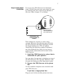
Loop-current detect
installation
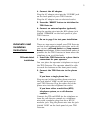
To set up your TDD Detector for Automatic
Loop Current Detection you must open the case
by removing the four screws in the bottom of
the case. Move Jumper J3 as follows:
From:
To:
J3
Move the jumper
from the bottom two
pins to the top two.
TDD Detector card
showing Jumper J3
location.
This enables the circuitry to detect loop
current. Whenever the operator goes off-hook,
the TDD Detector will detect this loop current
and begin looking for a TTY call. When
connecting the operator's phone (Telephone)
and the telephone line (Line), be sure not to
reverse these connections on the back of the
TDD Detector.
1. Install the TDD Detector in a place that is
convenient for your operator.
You can place the operator's telephone on top of
the TDD Detector. The operator should be able
to reach the buttons on the front panel easily.
2. Connect the TDD Detector to the phone
line.
Use the modular telephone wire included with
your TDD Detector.
If you have a single phone line…
Plug one end of the modular phone wire into
8
the jack labeled "LINE" on the back panel of
your TDD Detector. Plug the other end of the
phone wire into the telephone line outlet.
If you have either a multi-line (KTS)
telephone system, or a call-director
console…
Connect the TIP and RING for the KTS
telephone set or the TIP and RING from the
call-director console to a telephone wire. The
telephone wire must have a modular plug that
fits a RJ12C modular jack. Plug the phone wire
into the jack labeled "LINE" on the back panel
of your TDD Detector.
3. Connect the operator's telephone to the
TDD Detector.
Plug the phone wire from the TIP and RING of
the operator's telephone into the "TELEPHONE"
jack on the back panel of the TDD Detector. The
TDD Detector will use the telephone line loop
current to monitor the on-hook and off-hook
status of the operator's line.
4. Connect the AC adapter.
Plug the AC adapter wire into the "POWER" jack
on the back panel of your TDD Detector.
Plug the AC adapter into an electrical outlet.
5. Press the "RESET" button to initialize the
TDD Detector.
6. Connect an external speaker (optional).
Plug the speaker wire into the RCA phono jack
labeled "SPEAKER" on the back panel of your
TDD Detector.
7. Go on to page 9 to test your installation.
9
Test your installation
and train your operators
Test procedures
for manual and
automatic reset
installations
1. Check your phone line.
Pick up the receiver of a telephone connected to
a line that the TDD Detector is monitoring.
Listen to the dial tone on the line. It should
sound clear and loud.
2. Press the black "RESET" button on the
front panel.
3. Press the red "SEND" button.
You will hear a series of beeping sounds on the
phone line. The beeping sounds you hear are
the sounds of the TTY message (in Baudot code)
being sent over the line by the TDD Detector.
The message says, "TYPE YOUR NAME GA."
Touch-Tone commands can
be used by operators during
a call as well as for testing
the installation.
4. Test the Touch-Tone commands.
•
Lift the receiver on the operator's
telephone.
•
"SEND"—Type [#][#][1] on the telephone
keypad. This should initiate the "SEND"
function. You should hear the sound of
TTY signals on the line as the message,
"TYPE YOUR NAME GA" is sent.
•
"TEST"—Type [#][#][2] on the telephone
keypad. This is the "TEST" command. You
should hear a voice over the speaker
saying "TDD CALL… TDD CALL…" The
voice should sound clear and loud. Then
you should hear the "beeping" sounds of
the TTY message, "911 HERE PLEASE
HOLD." All the lights on the front panel of
the TDD Detector should come on, and
the receive circuitry in the unit is
automatically checked internally.
10
5. If you are using an external speaker to
broadcast the voice, type the [#][#][2]
TEST command, and adjust the "VOLUME"
control as the voice message is broadcast.
The "VOLUME" control is on the back panel of
the TDD Detector. The voice should sound
clear, and be loud enough to be heard easily.
6. Arrange for someone to call you with a
TTY to test your installation.
Tell the person who calls you to type on the TTY
keyboard to send TTY signals after you answer.
The TTY call should initiate the voice message
("TDD CALL… TDD CALL…") and the TTY
message ("911 HERE PLEASE HOLD") from the
TDD Detector.
Train your
operators
1. Read the operator's instructions that were
included in this packet.
Make sure to read the instructions that apply to
the installation procedure you have chosen for
your location– automatic reset or manual
reset installation.
Thorough training of your
operators in established
procedures for handling TTY
calls will help to assure
prompt response to people
calling by TTY.
2. Carefully review the operator's
instructions with your operators.
You might want to make copies of the
instructions for your operators. Make sure your
operators know how to recognize a "silent" call,
and what to do when they receive one. (See
page 2 of the Operator's Instructions.) Make
sure you have clearly established procedures
for how to handle TTY calls once they have been
received and identified.
3. Help your operators to become sensitive
to the needs of the deaf or hard of
hearing people who may be calling you.
The responsibility of using special TTY
equipment to respond to people who are deaf or
hard of hearing may be new to some of your
operators. Inviting a spokesperson from the
11
deaf community in your area to speak with your
operators can help them to become sensitive to
and aware of the special communication
problems faced by people who cannot hear.
4. Establish a regular testing procedure for
your TDD Detector.
You should regularly test three aspects of your
system:
1.
The TDD Detector itself. Test the TDD
Detector circuits regularly by using the
Touch-Tone® "TEST" command ([#][#][2]).
2.
The other equipment which supports the
TDD Detector, such as the phone lines,
etc.
3.
Your operators’ preparedness to receive a
TTY call. This includes not only how to
operate the equipment, but the operators’
general knowledge of TTYs and deafness.
The best way to be sure you are ready for TTY
calls is to have someone use a TTY to call your
number regularly. The calls should be made on
different days of the week and at different times
to be sure all your operators are prepared.
12
13
TDD Detector options,
service, and specifications
TDD Detector
options available
•
You can request any or all of
the following options for your
TDD Detector.
•
If your TDD
Detector needs
repair
Rack installation. You can order your
TDD Detectors for installation in your
telephone equipment rack. Order one
card in the rack for each line you want to
monitor.
Custom outgoing TTY message. Ultratec
can program your TDD Detector to send a
TTY message that you create.
•
Custom voice message. The standard
message, "TDD CALL… TDD CALL…" can
be reprogrammed to your specifications.
•
Custom time delay. When the TDD
Detector is installed in a manual reset
situation, it waits 10 minutes between
TTY calls and then resets itself. You can
specify a different time delay.
If you think your TDD Detector needs
repair or service…
•
Disconnect the TDD Detector from the
phone line.
•
Call the Ultratec National Service Center:
(608) 238-5400 (Voice/TTY)
Toll Free: (800) 482-2424 (Voice/TTY)
Ask for the Customer Service
Department.
•
Tell them that you are a 911 center and
that you require immediate assistance.
14
Ultratec offers 24-hour replacement
service for your TDD Detector…
•
If your TDD Detector needs repair or
service, Ultratec can send a replacement
or "loaner" unit to you within 24 hours.
To send your TDD Detector in for repair
or service…
•
Package it in its original shipping box.
•
Include a note that describes the problem
you are having. The note will help our
technicians complete your repair quickly.
•
Insure your TDD Detector when you ship
it. Ultratec is not responsible for any
damage that occurs to your unit during
shipping.
•
Send your TDD Detector to the Ultratec
National Service Center:
Ultratec National Service Center
5901 Research Park Blvd.
Madison, WI 53711
(608) 238-5400 (Voice/TTY)
Toll Free:
(800) 482-2424 (Voice/TTY)
If the detector is under warranty, Ultratec
will pay for the cost of repair.
A technical manual for the TDD Detector is
available from Ultratec.
15
TDD Detector
specifications
TESTING PROCEDURES:
All TDD Detectors go through extensive testing
procedures as part of Ultratec's quality control
program. These procedures include complete
computerized testing of the board set, and a 24hour hot/cold cycling of the unit while
operating. These tests, along with Ultratec's
standard quality assurance procedures (see the
Quality Assurance Manual), help to ensure that
the TDD Detector will meet the performance
criteria required of this kind of device.
PHYSICAL DIMENSIONS:
Size
1.40" high x 6.33" wide x 9.50"
deep
Weight
1.25 pounds
POWER:
Requirements 12 VDC (Nominal), 3 W
TELECOMMUNICATIONS:
Codes:
Detects Baudot (45.45 baud)
Sensitivity:
-45 dBm (minimum)
Baudot and Bell 103 Output:
-9 dBm (maximum)
Voice output: -25 dBm
FCC Part 68 approved:
FCC#: D8K7IB-19552-MD-N
REN: 0.5A
The TDD Detector is designed for indoor use
only.
16
Specifications for switches,
indicator lights, and
connectors
FRONT PANEL:
TTY SIGNAL
Off when monitoring the phone
line. On when TTY characters
are detected. Blinking after voice
and TTY messages have been
sent.
RESET
Sets TDD Detector to resume
monitoring the phone line.
SEND
For "silent" TTY calls, sends TTY
(Baudot code) message over the
phone line.
POWER
On when the TDD Detector has
power. Off when there is no
power.
BACK PANEL:
TELEPHONE
RJ12C jack connection for
operator's telephone.
LINE
RJ12C jack connection from CO
or call-director.
OFF-HOOK
3.5 mm jack for automatic reset
installation.
VOLUME
Controls output volume for
external speaker.
SPEAKER
Connect external speaker here.
(8 Ohms, 0.25 W maximum)
POWER
Connects AC adapter to power
outlet. (12 VDC @ 300 mA)
Appendix A
TDD Detector Rack Installation
Equipment Needed:
Screwdriver
Two 50-pin, male, micro-ribbon connectors
Procedure:
1.
Install the Ultratec TDD Detector Rack Enclosure in the Telephone
Communications Rack where desired. Position the 12VDC 10 Amp
power supply in the rack or close enough to it so that the 9-ft. power
cable can reach the TDD Detector Rack enclosure. Do not connect
the power cable to the TDD Detector rack or plug the power supply
into the 115-VAC power outlet.
2.
Remove all the cards from the TDD Detector Rack Enclosure by
unscrewing the 2 wing bolts, removing the restraining bar and then
pulling the cards out one at a time. Be careful of the TDD Detector
cards. They are static sensitive, and all precautions for static
sensitive electronic printed circuit boards should be observed. Note
the orientation of the cards before removing them in order to
correctly reinstall them later.
3.
Set the Auto/Manual switch on the back of the TDD Detector Rack
Enclosure to the desired position.
4.
Using a screwdriver, connect the 2 conductor power cable to the TDD
Detector Rack Enclosure. Be sure to Connect the +V (marked on the
cable end) to the +V terminal and the -V conductor to the -V
terminal on the back of the TDD Detector Rack Enclosure. CAUTION:
Connecting the power supply to the TDD Detector Rack Enclosure
with the wrong polarity may cause harm to the TDD Detector cards
when installed.
5.
Plug in one of the TDD Detector cards supplied with the TDD
Detector Rack Enclosure in Card Slot #1.
6.
Plug the power cord from the 12 VDC 10 Amp power supply into the
115 VAC power outlet and press the reset (Black) button for Card #1.
The Power LED should be glowing brightly and no other LEDs should
be on. (If the Rack is set for Auto mode the Auto LED will also be
on.)
7.
Press the Send (Red) Button and the Send LED will turn on. You
have now tested the rack for correct wiring of the power supply and
Auto/Manual mode selection.
8.
Disconnect the power supply from the 115VAC source.
9.
Connect the telephone lines to the 2 Micro-ribbon Male connectors
as indicated in the schematic diagram at the back of this manual
which shows the connectors on the back of the TDD Detector Rack
Enclosure.
Manual Connection - Connect only Tip# and Ring#. No other
connections are necessary.
Automatic Switch Connection - Connect the Tip#, Ring#, OH# and
the Ground as indicated on the diagram. TipL# and RingL# are not
to be connected. The OH# and its GND connection are the
connections to the open switch element indicating when the
telephone line is Off/On hook. These connections should go only to
the switch element. The OH# connection is internally biased on the
TDD Detector card so no outside power connections are required.
Automatic Loop Current Detection - In this mode the TDD
Detector card is placed in series ahead of the operator so that loop
current detection is accomplished. This requires 4 telephone line
connections to be made. Connect Tip# and Ring# as indicated. The
connections to the operator's equipment then come from the TipL#
and RingL# connections as shown on the diagram. Jumper J3 on the
TDD Detector card must be changed to the top position.
Note: The TDD Detector cards do not draw loop current. Therefore
loop current must be drawn by the operator's equipment for this
feature to operate (10mA. min).
10. Plug the 2 Micro-ribbon connectors into the back of TDD Detector
Rack Enclosure. Please note that Connector #1 is for lines 1-7 and
Connector #2 is for lines 8-15. Re-connect the 115 VAC power source
to the 12VDC power supply and press the Reset (Black) button on
Card #1 in the TDD Detector Rack Enclosure.
11. Perform the TDD Detector Installation Test (see below) for Card #1.
12. Disconnect the 115 VAC power source. Install the remaining TDD
Detector cards in the TDD Detector Rack Enclosure. Reinstall the
restraining bar using the 2 wing screws provided.
13. Re-connect the 115 VAC power source and press the Reset (Black)
button on each TDD Detector card. Test each line using the TDD
Detector Installation Test procedure given below.
TDD Detector Installation Test
1.
Place the operator's headset or telephone in an Off-Hook condition
and listen for dial tone. There should be no difference between the
sound before and after the TDD Detector connection.
2.
Using the Operators Touch Tone keypad press the sequence
"[#][#][2]". This will initialize the test sequence for the TDD Detector
Card. The LEDs will turn on and off, next the voice will be output
followed by the transmission of the Baudot (TTY Code) message "The
quick brown fox jumped over the lazy dog's back 1234567890".
3.
Use a TTY to call this line and test the TDD Detector Card for proper
TTY detection.
4.
Use the Send Button on the Card or "[#][#][1]" on the Touch Tone
keyboard to test the Send function.
The TDD Detector Rack Enclosure is now installed and tested. Ultratec
suggests that the individual cards (lines) be tested for proper operation at
regular intervals. The easiest way to test the lines (and familiarize the
operators with the TTY) is to make a TTY call into the 911 center.
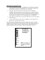
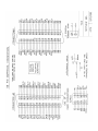
LED 1
LED 1
LED 2
LED 3
LED 4
LED 5
LED 6
=
=
=
=
=
=
Detect
Detect
Off-Hook
Automatic
Send
Power
LED 2
LED 3
LED 4
LED 5
LED 6
NOTE: On Card Rack units,
LEDs 1 & 6 are omitted. On
Stand-Alone units, LED 2 is
omitted.
TD3 card front showing indicator lights
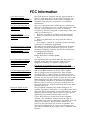
FCC Information
Your TDD Detector
generates radio frequency
energy, and may cause radio
or television interference.
Use your TDD Detector in
strict adherence with these
instructions.
If radio frequency
interference occurs, try to
correct it:
Your TDD Detector complies
with Part 68 of the Federal
Communications
Commission (FCC) Rules.
Use a Telephone Company
registered jack to connect
your to the nationwide
telephone network.
Use the Ringer Equivalence
Number (REN) to determine
how many direct connect
devices you can connect you
your telephone line.
Know the rights of your
Telephone Company.
Your TDD Detector complies with the regulations for a
Class A computing device as specified in Subpart J of
Part 15 of the FCC Rules. These rules are designed to
minimize radio frequency interference in residential
installations.
There is no guarantee that radio frequency interference
will not occur during use. You can determine if your TDD
Detector causes interference to radio or television
reception by disconnecting and reconnecting it while your
radio or television is on.
• Reorient the radio or television receiving antenna.
• Move your TDD Detector away from the receiving
antenna.
• Move your TDD Detector away from the radio or
television.
• If necessary, consult an experienced radio/television
technician for additional suggestions.
The label on the bottom of your TDD Detector presents
the following required information. You must, if your
Telephone Company requests, provide this information:
FCC Registration Number:
D8K7IB–19552-MD-N
Ringer Equivalence Number (REN):
0.5A
Use registered jack type USOC #RJ12C. This jack is a
modular outlet that you can order from your local
Telephone Company or telephone supply store.
FCC Rules do not permit you to connect your TDD
Detector to a pay telephone. Connection to party lines is
subject to local Telephone Company regulations.
Add up the REN numbers of all the direct connect
devices plugged into your phone line. This includes
telephones, direct connect TTYs, or products such as
your TDD Detector that plug directly into the phone line.
In most, but not all, areas of the country the sum of the
RENs should not be more than five (5.0). (Contact your
local Telephone Company to determine the maximum
REN for your local area.) If you plug too many devices
into your phone line, some of them may fail to ring when
someone calls you.
Your Telephone Company may make changes in its
facilities, equipment, operations, or procedures that could
affect the proper functioning of your TDD Detector. If this
happens, they will notify you in advance to give you the
opportunity to maintain uninterrupted service.
If your TDD Detector causes harm to the telephone
network, your Telephone Company has the right to
discontinue your service temporarily. If possible, they will
notify you in advance. But if advance notice is not
practical, they will notify you as soon as possible. You
will have the opportunity to correct the situation, and
you will be informed of your right to file a complaint with
the FCC.