1
Operation/Reference Guide
AXB-DMX512
DMX512 Interface
Axcess Controllers
Last Revised: 09/25/2012
AMX Limited Warranty and Disclaimer
All products returned to AMX require a Return Material Authorization (RMA) number. The RMA number is
obtained from the AMX RMA Department. The RMA number must be clearly marked on the outside of each
box. The RMA is valid for a 30-day period. After the 30-day period the RMA will be cancelled. Any shipments
received not consistent with the RMA, or after the RMA is cancelled, will be refused. AMX is not responsible
for products returned without a valid RMA number.
Warranty Repair Policy
•
AMX will repair any defect due to material or workmanship issues during the applicable warranty period at no cost to the AMX
Authorized Partner., provided that the AMX Authorized Partner is responsible for in-bound freight and AMX is responsible for
out-bound ground freight expenses.
•
The AMX Authorized Partner must contact AMX Technical Support to validate the failure before pursuing this service.
•
AMX will complete the repair and ship the product within five (5) business days after receipt of the product by AMX. The AMX
Authorized Partner will be notified if repair cannot be completed within five (5) business days.
•
Products repaired will carry a ninety (90) day warranty or the balance of the remaining warranty, whichever is greater.
•
Products that are returned and exhibit signs of damage or unauthorized use will be processed under the Non-Warranty Repair
Policy.
•
AMX will continue to provide Warranty Repair Services for products discontinued or replaced by a Product Discontinuance
Notice.
Non-Warranty Repair Policy
•
Products that do not qualify to be repaired under the Warranty Repair Policy due to age of the product or Condition of the product may be repaired utilizing this service.
•
The AMX Authorized Partner must contact AMX Technical Support to validate the failure before pursuing this service.
•
Non-warranty repair is a billable service.
•
Products repaired under this policy will carry a ninety (90) day warranty on material and labor.
•
AMX will notify the AMX Authorized Partner with the cost of repair, if cost is greater than the Standard Repair Fee, within five (5)
days of receipt.
•
The AMX Authorized Partner must provide a Purchase Order or credit card number within five (5) days of notification, or the
product will be returned to the AMX Authorized Partner.
•
The AMX Authorized Partner will be responsible for in-bound and out-bound freight expenses.
•
Products will be repaired within ten (10) business days after AMX Authorized Partner approval is obtained.
•
Non-repairable products will be returned to the AMX Authorized Partner with an explanation.
•
See AMX Non-Warranty Repair Price List for minimum and Standard Repair Fees and policies.
Table of Contents
Table of Contents
Product Information ...........................................................................................1
Specifications............................................................................................................ 1
Configuration and Installation ............................................................................3
Setting the Device DIP Switch .................................................................................. 3
Terminating the Device............................................................................................. 3
Wiring Devices to the AXB-DMX512 ........................................................................ 4
Preparing/connecting captive wires ................................................................................ 4
Wiring guidelines ............................................................................................................ 4
Using AxLink communication .................................................................................... 5
Using IN and OUT DMX512 data communication ..................................................... 5
Transmit Wiring............................................................................................................... 5
Receive Wiring ................................................................................................................ 5
Mounting the AXB-DMX512 in a Rack ...................................................................... 5
Replacing the Lithium Battery................................................................................... 6
Programming ......................................................................................................9
Buffers ...................................................................................................................... 9
Direct Control Buffer Send_Commands .................................................................. 10
DL ........................................................................................................................................... 10
DR........................................................................................................................................... 10
Patch Buffer Send_Commands................................................................................ 11
PA ...........................................................................................................................................
DS ...........................................................................................................................................
DZ...........................................................................................................................................
PC ...........................................................................................................................................
PX ...........................................................................................................................................
PZ ...........................................................................................................................................
11
11
11
12
12
12
Group Buffer Commands ........................................................................................ 13
GA ..........................................................................................................................................
GC ..........................................................................................................................................
GD ..........................................................................................................................................
GE...........................................................................................................................................
GF...........................................................................................................................................
GL ...........................................................................................................................................
GO ..........................................................................................................................................
GP...........................................................................................................................................
GR...........................................................................................................................................
GS...........................................................................................................................................
GT...........................................................................................................................................
GU ..........................................................................................................................................
13
14
15
15
15
16
16
17
18
18
19
19
Axcess Level Send_Commands ............................................................................... 20
AC........................................................................................................................................... 20
GX .......................................................................................................................................... 20
Document Name Here
i
Table of Contents
GZ ..........................................................................................................................................
AD ..........................................................................................................................................
AR ..........................................................................................................................................
AS...........................................................................................................................................
AT...........................................................................................................................................
AU ..........................................................................................................................................
AX ..........................................................................................................................................
AZ ..........................................................................................................................................
20
21
21
21
22
22
22
22
Miscellaneous Send_Commands ............................................................................. 23
MB..........................................................................................................................................
MD .........................................................................................................................................
MG .........................................................................................................................................
MI...........................................................................................................................................
ML ..........................................................................................................................................
MM.........................................................................................................................................
MO .........................................................................................................................................
MP..........................................................................................................................................
23
23
23
23
24
24
24
24
Channel Commands ................................................................................................ 25
MR.......................................................................................................................................... 25
MZ.......................................................................................................................................... 25
Channel Trigger Send_Commands .......................................................................... 26
CA .......................................................................................................................................... 26
CL ........................................................................................................................................... 26
CZ........................................................................................................................................... 26
Troubleshooting ...............................................................................................27
ii
Document Name Here
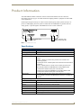
Product Information
Product Information
The AXB-DMX512 DMX512 Interface creates a bi-directional DMX512 AxLink connection,
transmitting and receiving up to 512 DMX channels for lighting dimmers, spotlights, and other DMX
control applications.
Onboard processing and memory can create and store channel groups, faders, patches, and up to 72
presets. A DMX lighting board can operate in tandem with the AXB-DMX512, generate levels for
storing presets, or pass through the AXB-DMX512 for direct control of channels.
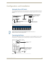
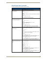
DEVICE
AXlink
TX
RX
ON
Device ID DIP Switch
Axlink activity LED
DMX512 (Receive) LED
DMX512 (Transmit) LED
FIG. 1 AXB-DMX512 (front view)
Specifications
AXB-DMX512 Specifications
Power consumption
160 mA @ 12 VDC
Power supply
12 VDC
Front panel components:
LED Indicators
• AxLink LED (green and blinks to indicate AxLink communication activity and
power:
Full-Off indicates no power is being received or the controller is not
functioning properly.
One blink per second indicates power is active and AxLink communication is
functioning.
Full-On indicates there is no AxLink control or activity, but power is On.
• RX LED (red) indicates the AXB-DMX512 is receiving DMX512 data.
Corresponds to the IN and OUT ports on the rear panel.
• TX LED (red) indicates the AXB-DMX512 is transmitting DMX512 data.
Corresponds to the IN and OUT ports on the rear panel.
DIP switches
• 8-position DEVICE DIP switch sets the AxLink address for the DMX512.
• The DIP Switch to the right of the DEVICE DIP is reserved - no settings are
required.
Rear panel components:
DMXIN port
5-wire, captive-wire connector for receiving data.
DMXOUT port
5-wire, captive-wire connector for transmitting data.
AxLink
4-wire, captive-wire connector for data and power.
Dimensions (HWD)
1.5" x 5.5" x 5.5" (38 mm x 140 mm x 140 mm)
Enclosure
Metal with black matte finish
Mounting
Rack mounting with the optional AC-RK Accessory Rack Kit
Weight
1.1 lb (0.5 kg)
AXB-DMX512 DMX512 Interface
1
Product Information
2
AXB-DMX512 DMX512 Interface
Configuration and Installation
Configuration and Installation
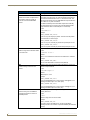
Setting the Device DIP Switch
The 8-position DEVICE DIP switch on the front panel (FIG. 1) sets the AxLink identification number for
the AXB-DMX512. Make sure the device number matches the number assigned in the Axcess software
program.
The DIP Switch located to the
right of the DEVICE DIP switch
is not used - no settings are
required, and any setting
will work.
DEVICE
AXlink
TX
RX
ON
Device ID DIP Switch
AxLink activity LED
DMX512 (Receive) LED
DMX512 (Transmit) LED
FIG. 1 AXB-DMX512 (front view)
The following table describes the values on the DEVICE DIP switch.
Device DIP Switch Settings
Position
1
2
3
4
5
6
7
8
Value
1
2
4
8
16
32
64
128
The DIP Switch located to the right of the DEVICE DIP switch is not used - no
settings are required, and any setting will work.
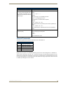
Terminating the Device
When using the DMX input and if this device is the last device in a chain of DMX512 devices, you must
terminate the line. To terminate the device, position jumpers on jumper pin trios JP4 and JP5 (FIG. 2):
JP5
Termination Jumpers
(JP4 / JP5)
JP4
COR
The DIP Switch located to the
right of the DEVICE DIP switch
is not used - no settings are
required, and any setting
will work.
front
DEVICE DIP Switch
FIG. 2 Location of termination jumpers pins (JP1-JP5) and lithium batteries
AXB-DMX512 DMX512 Interface
3
Configuration and Installation
1. Remove the jumper that is on pins 1 and 2 of jumper trios JP4 and JP5. (Pins 1 and 2 are marked
HIZ - see FIG. 3).
2. Place the jumper on pins 2 and 3 of jumper trios JP4 and JP5. (Pins 2 and 3 are marked TERM -see
FIG. 3). This terminates the incoming DMX input with a 120 ohm resistor.
TERM
HIZ
FIG. 3 Termination jumper pin settings for JP4 and JP5
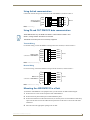
Wiring Devices to the AXB-DMX512
OUT
AXP
PWR
AXM
GND
NC
DATA 2
DATA 2
DATA 1
GND
IN
DATA 1
NC
DATA 2
DATA 2
DATA 1
GND
DATA 1
The AXB-DMX512 has three captive-wire connectors on the rear panel (FIG. 4) for DMX512 transmit
and receive, and AxLink.
AXlink
FIG. 4 AXB-DMX512 (rear view)
Preparing/connecting captive wires
1. Strip 0.25 inch of wire insulation off all wires.
2. Insert each wire into the appropriate opening on the connector according to the wiring diagrams and
connector types described in this section. Do not tighten the screws excessively; doing so may strip
the threads and damage the connector.
Wiring guidelines
The interface requires a 12 VDC power to operate properly. The Central Controller supplies power via
the AxLink cable or external 12 VDC power supply. The maximum wiring distance between the Central
Controller and interface is determined by power consumption, supplied voltage, and the wire gauge used
for the cable. The table below lists wire sizes and maximum lengths allowable between the AXBDMX512 and Central Controller. The maximum wiring lengths for using AxLink power are based on a
minimum of 13.5 volts available at the Central Controller’s power supply.
Wiring Guidelines at 160 mA
Wire Size Maximum Wiring Length
4
18 AWG
733.57 feet (223.59 m)
20 AWG
464.11 feet (141.46 m)
22 AWG
289.35 feet (88.19 m)
24 AWG
182.39 feet (55.59 m)
AXB-DMX512 DMX512 Interface
Configuration and Installation
Using AxLink communication
Connect the AxLink wiring to the connector on the AXB-DMX512, as shown in FIG. 5.
AxLink connector
on AXB-DMX512
PWR
PWR
AXP
AXP
AXM
AXM
GND
GND
Device
FIG. 5 AxLink wiring
Using IN and OUT DMX512 data communication
Some DMX devices only use DATA+ and DATA-. Connect these to DATA1+ and
DATA1-, leaving DATA2+ and DATA- unconnected.
The DATA2 In and Out ports are not Currently supported.
Transmit Wiring
For transmit wiring, connect the DMX512 wiring to the OUT connector, as shown in FIG. 6.
GND
DMX 512 OUT
connector on AXB-DMX512
GND
DATA1-
DATA1-
DATA1+
DATA1+
DATA2-
DATA2-
DATA2+
DATA2+
Device
NC
FIG. 6 DMX512 transmit wiring
Receive Wiring
For receive wiring, connect the DMX512 wiring to the IN connector, as shown in FIG. 7.
GND
DMX 512 IN
connector on AXB-DMX512
GND
DATA1-
DATA1-
DATA1+
DATA1+
DATA2-
DATA2-
DATA2+
DATA2+
Device
NC
FIG. 7 DMX512 receive wiring
Mounting the AXB-DMX512 in a Rack
To mount the AXB-DMX512 in an equipment rack, you will need an AC-RK rack mounting kit.
1. Remove the two screws on the front panel of the AXB-DMX512.
2. Remove the front panel and the space bracket behind the panel.
3. Remove the rubber feet on the bottom of the unit, if necessary. Insert a scissors blade or other sharp
object into the side of one of the rubber feet and pull it off. Do the same to remove the other three
rubber feet.
4. Place the unit in the appropriate opening in the AC-RK.
AXB-DMX512 DMX512 Interface
5
Configuration and Installation
5. Place the front panel of the AXB-DMX512 on the front of the rack over the unit and secure the
screws.
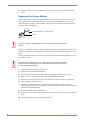
Replacing the Lithium Battery
A lithium battery (FIG. 8) with a life of approximately 5 years, protects stored presets if a power loss
occurs. The battery is not used when DC power is supplied to the AXB-DMX512. Write down the
replacement date on a sticker or label by adding 5 years to the date of installation, and then attach it to
the bottom of the AXB-DMX512.
Battery (CR2032 type - 20mm coin cell)
socket
FIG. 8 Lithium battery and socket
All control commands in AXB-DMX512 memory are lost when the lithium battery is
replaced
Contact your AMX dealer before you replace the lithium battery and verify that they have a current copy
of the Axcess program for your AXB-DMX512. This will avoid any inadvertent loss of data or a service
outage.
You will need a flat-blade tool (non-conducting) that can be slipped under the lithium battery to pry it up
and out of the socket.
Static electricity can damage electronic circuitry. Before removing the lithium battery
from the enclosure, discharge any accumulated static electricity from your body by
touching a grounded metal object.
1. Discharge the static electricity from your body.
2. Unplug all cables from the AXB-DMX512.
3. Remove the AC-RK and AXB-DMX512 from the mounting rack. Otherwise, go to step 4.
4. Remove the five pan-head screws on the top of the AXB-DMX512 enclosure.
5. Pull the two enclosure halves apart and set the bottom portion of the enclosure on a flat surface.
6. Locate the battery on the circuit card.
7. Carefully pry the battery out of its socket and insert the new battery. Write down the next
replacement date on a sticker or label by adding 5 years to the replacement date, and then attach it to
the bottom of the AXB-DMX512.
8. Plug all cables back into the AXB-DMX512.
9. Place the top portion of the enclosure back onto the bottom portion. Then, refasten the five pan-head
screws.
10. Reconnect the cables removed for battery replacement.
6
AXB-DMX512 DMX512 Interface
Configuration and Installation
There is a danger of explosion if you replace the battery incorrectly. Replace the
battery with the same or equivalent type recommended by the manufacturer. Dispose
of used battery according to the manufacturer's instructions. Never recharge,
disassemble, or heat the battery above 212 °F (100 °C). Never solder directly to the
battery or expose the contents of the battery to water.
AXB-DMX512 DMX512 Interface
7
Configuration and Installation
8
AXB-DMX512 DMX512 Interface
Programming
Programming
The AXB-DMX512 is controlled with Axcess Send_Commands. Use the programming information in
this section along with the Axcess Programming Language Instruction Manual to program the AXBDMX512.
All Send Commands are limited to 64 characters.
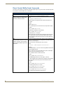
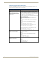
Buffers
The AXB-DMX512 uses a “highest value takes precedence” to determine which DMX value is actually
output (see FIG. 1). There are three output buffers: patch, group, and direct control. Each buffer
represents all 512 DMX outputs. The highest value in any buffer is the value transmitted from the output
port. The actual DMX output refers to the value being transmitted.
DMX Input
Patch Buffer
Group Buffer
Actual DMX Output
The highest value of any buffer
Direct Control Buffer
FIG. 1 DMX Flow Chart
The levels in the patch buffer are modified by DMX Input. The patch buffer commands determine which,
if any, DMX inputs modify the level of the patch buffer. A patch disconnect automatically clears the
value in the patch buffer to zero. If there is no DMX Input for 5 seconds, all values in DMX Input buffer
are set to zero. Any outputs tied those DMX Inputs will then be zero.
The group buffer is modified by changing group commands. Groups can ramp over time. Groups can be
tied to Axcess levels or DMX Inputs. The groups can be absolute or proportional. For groups that are
absolute, the value of all outputs are the same as the group level. Proportional group outputs depend on a
specified value or the Actual DMX output at the time the output is added to the group. That value sets the
maximum value the outputs can reach when controlled by group 55.
The direct control buffer is modified by individual output ramps or by preset recalls. Presets are also
called snapshots or scenes.
AXB-DMX512 DMX512 Interface
9
Programming
Direct Control Buffer Send_Commands
The direct control buffer is modified by individual output ramps or by preset recalls. The following table
lists the Direct Control Buffer Send_Commands.
Direct Control Buffer Send_Commands
Command
Description
DL
Time is required here. This affects all DMX512 channels.
Recalls a snapshot of all DMX output
channel in T tenths of seconds.
Syntax:
"'DL<preset number>T<time>'"
If a Direct Ramp is in progress the last command sent will win for
each output.
Variables:
preset number =1-72
time = 0-65535 (time is in tenths of seconds, except where noted).
Examples:
SEND_COMMAND DMX,'DL1T0'
Recalls preset 1 instantly (in zero seconds).
SEND_COMMAND DMX,'DL72T15'
Recalls preset 72 in 1.5 seconds.
Use the groups and group ramp (‘GR’) command to store and recall
scenes with specific channels. Any other snapshot recall or direct
ramp in progress is halted and the ramp to the new level starts from
the current level.
DR
The list can be single outputs and/or ranges of outputs separated by
Ramps the DMX output to the L level in commas. If a Snapshot Preset is in progress then the last command
T tenths of seconds. Time is required. sent will win for each output.
Sends all specified DMX outputs to the Do not put more 64 characters total in this command.
same level.
Syntax:
"'DR<List of DMX Outputs>L<level>T<time>'"
Variables:
List of DMS Output = 1,2,3,5-10 is a list of single DMX channels with
ranges of DMX channels.
level = 0-255 or 0%-100%. The value can be given in actual steps
0-255 or given as a percentage 0%-100%.
time = 0-65535. Time is in tenths of seconds.
Example:
SEND_COMMAND DMX,'DR1L100%T10'
Ramps DMX Output channel 1 to 100% (full) in 1 second.
Any other snapshot recall or direct ramp in progress for the specified
channels is halted and the ramp to the new level starts from the
current level.
Example:
SEND_COMMAND DMX,'DR1-512L50%T10'
Sends all channels to 50% in 1 second.
SEND_COMMAND DMX,'DR1-512L127T25'
Sends all channels to 50% in 2.5 seconds.
SEND_COMMAND DMX,'DR10,20-30,35L0T0'
Sends channels 10,20 through 30, and 35 to 0%.
10
AXB-DMX512 DMX512 Interface
Programming
Direct Control Buffer Send_Commands
Command
Description
DS
This is the final output of the DMX512 box and is also affected by the
values in the Patch and Group Buffers.
Stores a snapshot of all DMX output
channels.
Note that this command stores all DMX512 channels, even channels
that are not currently being transmitted through the use of the ‘ML’
command (refer to theMiscellaneous Send_Commands section on
page 23).
Syntax:
"'DS<preset number>'"
Variable:
preset number = 1-72
Examples:
SEND_COMMAND DMX,'DS1'
Stores preset 1.
SEND_COMMAND DMX,'DS72'
Stores preset 72 (there is a max of 72 presets with standard memory).
To exclude (undefine) channels, the Group Buffer Commands must
be used, NOT the Direct Buffer Commands.
DZ
Clears all values in the Direct Control Buffer to zero.
Sends all outputs in the Direct Control
buffer immediately to zero.
Syntax:
"'DZ'"
Stops all 'DR' ramps.
Patch Buffer Send_Commands
The patch buffer Send_Commands determine which if any DMX inputs modify the patch buffer. The
following table lists the Patch Buffer Send_Commands.
Patch Buffer Send_Commands
Command
Description
PA
This is typically the second step (after clearing the memory), when
setting up the DMX512 box to sit between a lighting console and its
dimmers. The outputs immediately change to reflect the inputs and
will track any input changes.
Patches inputs 1-512 in a one-to-one
relationship with outputs 1-512.
Syntax:
"'PA'"
Globally connects all DMX inputs to DMX outputs in a 1 to 1
relationship.
AXB-DMX512 DMX512 Interface
11
Programming
Patch Buffer Send_Commands (Cont.)
Command
Description
PC
The list can be single outputs and/or ranges of outputs separated by
commas. If the output is currently already patched to another input,
then it is automatically disconnected from that input.
Patches an input to one or more
outputs.
Syntax:
"'PC<DMX input>D<list of DMX outputs>'"
Variables:
DMX Input = 1-512. The actual DMX inbound data is stored in the
DMX Input Buffer
DMX Output = 1-512
Example:
SEND_COMMAND DMX,'PC1D1,3,5-7'
Connects DMX Input 1 to DMX Outputs 1,3,4,6.
SEND_COMMAND DMX,'PC1D1-512'
Connects input 1 to all outputs.
SEND_COMMAND DMX,'PC1D10-20,25'
Patches input 2 to outputs 10 through 20 and 25.
PX
Disconnects a DMX output from any
DMX input by unpatching one or more
DMX outputs.
The list can be single outputs and/or ranges of outputs separated by
commas. These outputs immediately go to zero in the Patch buffer.
Syntax:
"'PX<list of DMX outputs>'"
Do not put more 64 characters total in this command. A Disconnect
will clear the Patch Buffer for that output to 0.
Variable:
list of DMX outputs
Example:
SEND_COMMAND DMX,'PX512'
Unpatches all DMX outputs (the same as the ’PZ’ command).
SEND_COMMAND DMX,'PX15,20-25'
Unpatches DMX outputs 15 and 20 through 25.
PZ
Global delete all DMX outputs from any DMX input.
Unpatches all DMX inputs from all
DMX outputs.
Syntax:
"'PZ'"
All DMX outputs in the Patch Buffer immediately go to zero.
12
AXB-DMX512 DMX512 Interface
Programming
Group Buffer Commands
The group buffer is modified by changing group commands.
There is a maximum of 96 groups in software version 1.10.
Adding outputs to a group while the group is still connected to an Axcess level DMX
output can cause the value of outputs, which are already a member of the group, to
change.
The following table lists the Group Buffer Send_Commands.
Group Buffer Commands
Command
Description
GA
The list can be single outputs and/or ranges of outputs separated by
commas. A DMX output can only belong to one group at a time.
Adds one or more DMX outputs to a
group.
Any of these outputs, that are currently members of another group,
are automatically removed from that group. Adding an output to the
group does not change the current DMX value for that output in the
Group Buffer. This means that its possible to have different DMX
values for the channels in this group at the time the channels are
added, but this command is intended for the control of a group of
outputs that will have the same value at all times.
Syntax:
"'GA<group>D<list of DMX output>'"
Variables:
group = 1-96
list of DMX output = 1,2,3,5 - 10
If this group is direct ramped (‘GR’) to a level, then the offset between
channels will be lost.
If this group is ramped up (‘GU’) or down (‘GD’), then the channels
maintain their relative values until these channels hit zero or full. This
effectively ‘clips’ the channels and eliminates the offsets between the
values.
Example:
SEND_COMMAND DMX,'GA1D1,3,5-7'
Adds DMX Output Channels 1, 3, 5, 6, 7 to Group 1.
SEND_COMMAND DMX,'GA1D-5'
Adds DMX outputs 1 through 5 to Group 1.
SEND_COMMAND DMX,'GA96D6,10'
Adds DMX Outputs 6 and 10 to Group 96.
AXB-DMX512 DMX512 Interface
13
Programming
Group Buffer Commands (Cont.)
Command
Description
GC
A group can only be tied to one or the other not both. The list can be
single groups and/or ranges of groups separated by commas.
Connects one or more groups to an
Axcess level or to a DMX input.
Syntax:
"'GC<list of groups><A or D><Axcess level or DMX
input>'"
Variables:
Axcess level = 1-8
DMX input = 1-512
If a single group is connected to an unconnected Axcess level, then
the Axcess level value will change to the group value. Otherwise, the
group value will change to the Axcess level.
There are 4 possible scenarios with this command:
Connecting a single group to an Axcess level: The Axcess level
changes immediately to reflect the current level of the group for normal groups. The group level immediately changes to reflect the
Axcess level for proportional groups and fixed groups. The group can
now be ramped up and down via the Axcess level ramp commands
(‘AU’, ‘AD’, and ‘AS’). It is no longer possible to use the group ramp
up (‘GU’) or down (‘GD’) commands, but the direct ramp command
(‘GR’) and Axcess channels still work, and also affects the Axcess
level. If the group is disconnected using the ‘GX’ command, the group
ramp up and down will work again.
Example:
SEND_COMMAND DMX,'GC1A2'
Connects Group 1 to Axcess level 2.
Connecting multiple groups to an Axcess level: The group levels
change immediately to reflect the current Axcess level. The group can
now be ramped up and down via the Axcess level. It is no longer possible to use the group ramp up (‘GU’) or down (‘GD’) commands. The
direct ramp command (‘GR’) and Axcess channels still work but now
controls all groups connected to this Axcess level, as well as the
Axcess level itself.
Example:
SEND_COMMAND DMX,'GC1,2A3'
Connects Groups 1 and 2 to Axcess level 3.
Connecting a single group to a DMX level: The group level changes
immediately to reflect the current DMX input level. The group can now
be ramped up and down by the DMX input level. There are no other
means of affecting the group output.
Example:
SEND_COMMAND DMX,'GC4D5'
Connects Group 4 to DMX input 5.
Connecting multiple groups to a DMX level: The group levels change
immediately to reflect the current DMX input level and behave the
same as connecting a single group to the DMX input.
Example:
SEND_COMMAND DMX,'GC1-3,5D8'
Connects Groups 1 through 3 and 5 to DMX input 8.
14
AXB-DMX512 DMX512 Interface
Programming
Group Buffer Commands (Cont.)
Command
Description
GD
The group stop (‘GS’), group ramp down (‘GD’), or group direct ramp
command (‘GR’) will interrupt this command. It is not possible to use
this command on groups that are connected to an Axcess level or to a
DMX input.
Ramps down one or more groups at
the current ramp rate set by the ‘GT’
command.
Syntax:
"'GD<list of groups>'"
The list can be single groups and/or ranges of groups separated by
commas. If this command is sent for multiple groups, only those that
are connected to an Axcess level or DMX input will ramp.
Example:
SEND_COMMAND DMX,'GD1,3-4'
Starts a ramp down on groups 1, 3, and 4.
GE
Erases groups.
Removes all output channels from one or more groups. These outputs
go immediately to 0% in the Group buffer and do not disconnect an
Axcess level or DMX input from the group, if it is currently connected.
If a programmer later adds channels back to the groups, they will be
immediately be connected to the Axcess level or the DMX input.
The list can be single groups and/or ranges of groups separated by
commas.
Syntax:
"'GE<list of groups>'"
Removes all DMX outputs from the groups. Sets all levels in the group
buffer to zero.
Example:
SEND_COMMAND DMX,'GE1'
Removes all output channels from Group 1.
SEND_COMMAND DMX,'GE5,8-10'
Removes all output channels from Groups 5 and 8 through 10.
GF
This is useful for creating “blind” presets, meaning that its not
necessary to drive the actual DMX outputs to these levels in order to
Functions like the ‘GP’ command,
except the Max value for each output is store the preset. All other rules for use are identical to those of the
‘GP’ command.
specified in the Send Command.
Syntax:
"'GF<group>D<special list of DMX outputs with
maximum value>'"
Variables:
group = 1-96
special list of DMX outputs with maximum value = 1-512
Example:
SEND_COMMAND DMX,'GF1D1@100%,2@50%,8@75%'
Adds channels 1,2, and 8 to Group 1 at levels of 100%, 50%, and
75% respectively.
SEND_COMMAND DMX,'GF10D5-10@255,20@50%'
Adds channels 5 through 10 at 100% (255) and channel 20 at 50% to
Group 10.
After the output there is an ampersand (@), then the maximum value
for that output. That means the highest the DMX output can ever be is
the value given at the time of the add. Ranges are allowed but can
only have one maximum value for whole range.
AXB-DMX512 DMX512 Interface
15
Programming
Group Buffer Commands (Cont.)
Command
Description
GL
This command removes one or more output channels from the group
that they are connected to. These outputs go immediately to 0% in the
Group buffer.
Deletes DMX outputs from any group.
DO NOT specify which group these are to be removed from, because
a channel can only be a member of one group at a time.
The list can be single outputs and/or ranges of outputs separated by
commas.
Syntax:
"'GL<list of DMX outputs>'"
Variable:
list of DMX outputs = 1-512
Example:
SEND_COMMAND DMX,'GL1-50'
Removes DMX channels 1 through 50 from any group.
SEND_COMMAND DMX,'GL5,10,20-25'
Removes DMX channels 5, 10, and 20 through 25 from any group.
GO
Sets the current output values in the
Groups to the same value as the
current actual DMX output.
This command copies the actual output levels for the AXB-DMX512
box to the Group buffer for one or more groups.
Syntax:
"'GO<list of groups>'"
This has the effect of copying the highest value from the patch or
direct control buffer into the group buffer if they are higher than the
value in the Group buffer.
This is useful in the event a programmer wishes to add a group and
then ramp it down from its current level. To do this:
Use the Direct or Patch buffer to set the DMX outputs as needed.
Add one or more groups using the ‘GP’ command.
Use group copy (‘GO’) to copy the box outputs to the group buffer
for these groups.
Disconnect the Patch buffer (‘PZ’) or send the Direct buffer (‘DZ’)
to 0%.
Example:
SEND_COMMAND DMX,'GO1'
Copies outputs for all channels in Group 1 to the Group buffer.
SEND_COMMAND DMX,'GO5-8'
Copies outputs for all channels in Groups 5 through 8 to the Group
buffer.
Warning: The ‘GO’ command only works normal
(non-proportional) groups. To work around this, use the direct
ramp (‘DR’) command to set each group to full, instead of using
the ‘GO’ command.
16
AXB-DMX512 DMX512 Interface
Programming
Group Buffer Commands (Cont.)
Command
Description
GP
The highest the DMX output can ever be is the value at the time of the
add. A DMX output can only belong to one group at a time.
Same as ‘GA’ command, except the
DMX outputs are added so they will
remain proportional to the value they
had at the time of adding the output.
The outputs will not ramp to a value above that which they had at the
time they were added. This is the command typically used to store
scenes that were created on a DMX console that is providing the
DMX inputs to the AXB-DMX512 unit. When the group is ramped, the
outputs retain their same proportional level to each other.
Warning: Rounding errors occur in the algorithym that controls the
proportional levels (this function is unsuitable for precision control).
Syntax:
"'GP<group>D<list of DMX output>'"
Variables:
group = 1-96
list of DMX output = 1,2,3,5 -10
If an output is added to an existing group, the its proportional value is
determined by its value when compared to the maximum values for
each channel in a group; not by its value compared to the current
values for each channel in the group.
As with the ‘GA’ command, this can cause things to be a bit out of
sync at the time of adding. When any channel is added, its output
value in the Group Buffer does not change, regardless of what level
other outputs in the group might currently be at.
When ramping up (‘GU’) or down (‘GD’), the other levels will reach
their maximum or minimum before the currently added level does.
Once all levels have reached maximum or minimum, they will ramp
together from that point forward.
AXB-DMX512 DMX512 Interface
17
Programming
Group Buffer Commands (Cont.)
Command
Description
GR
Ramps a single group to a level. Time is optional and if no time is
specified, the group time (set by the ‘GT’ command) is used and then
it will ramp at the current ramp rate for that group. If a group is tied to
a DMX input, then this command is ignored. If the group is tied to an
Axcess level the group will ramp.
Ramps group to a L level in T tenths of
seconds.
This can be interrupted by the group up (‘GU’), group down (‘GD’), or
group stop (‘GS’) commands. Inaccuracies in the value, as a result of
rounding, are common with fixed and proportional groups. Even if the
group is set to 100%, some of the channels will still not be at their
stored levels. The group up (‘GU’) command can be issued to take
the groups to their true 100% level.
Syntax:
"'GR<group>L<level>{T<time>}'"
Variables
group = 1-96. The group of DMX output that act together. Outputs
can only belong to one group at a time.
level = 0-255 or 0%-100%
time = 0-65535
{}-Parameters in commands that are optional.
Examples:
SEND_COMMAND DMX,'GR1L0T10'
Ramps all DMX output channels in group 1 to zero (lowest) in 1
second.
SEND_COMMAND DMX,'GR1L50%T20'
Ramps Group 1 to 50% in 2 seconds.
SEND_COMMAND DMX,'GR2L255'
Ramps Group 2 to 100% using the group time.
GS
Stops ‘GU’,’GD’,’GR’.
Stops any ramping that was started by
the group up (‘GU’), group down
(‘GD’), or group direct ramp (‘GR’)
commands.
Syntax:
"'GS<list of groups>'"
The list can be single groups and/or ranges of groups separated by
commas. DMX outputs freeze at their current level.
Example:
SEND_COMMAND DMX,'GS1,3-4'
Stops a ramp on Groups 1, 3, and 4.
18
AXB-DMX512 DMX512 Interface
Programming
Group Buffer Commands (Cont.)
Command
Description
GT
This affects any future group up (‘GU’), group down (‘GD’), or group
direct ramp (‘GR’) commands. The specified time determines how
long it takes to go full range. If the group is proportional then
Individual Output rates will be proportional.
Sets the current ramp rate for one or
more groups in tenths of a second.
Optionally, the up (‘U’) or down (‘D’) times may be specified. Without
an U or D, both up and down ramp rates are set the same. Ramp
rates determine how long the group will take to ramp from 0% to
100% (and 100% to 0%).
If, for example, there is a ramp time of 10 seconds, and the level is
currently at 50%, it will take only 5 seconds to ramp to either 0% or
100%. 100% for proportional (‘GP’) and fixed (‘GF’) groups is the
maximum level in the group for each channel that is not necessarily
fully at 100% (255).
Syntax:
"'GT<list of groups>R<time>{U or D}'"
Variables:
{}-Parameters in commands that are optional.
Example:
SEND_COMMAND DMX,'GT1R5'
Sets Group 1 to ramp rate to 0.5 second both up and down.
SEND_COMMAND DMX,'GT1-2R50'
Sets the up and down ramp times for Groups 1 and 2 to 5 seconds.
SEND_COMMAND DMX,'GT3,5-8R35U'
Sets the up ramp time for groups 3 and 5 through 8 to 3.5 seconds.
SEND_COMMAND DMX,'GT10R5D'
Sets the down ramp time for Group 10 to 0.5 seconds.
GU
Ramps up one or more groups at the
current ramp rate set by the ‘GT’
command.
The group stop (‘GS’), group ramp down (‘GD’), or group direct ramp
command (‘GR’) will interrupt this command. It is not possible to use
this command on groups that are connected to an Axcess level or to a
DMX input.
Syntax:
"'GU<list of groups>'"
The list can be single groups and/or ranges of groups separated by
commas. If this command is sent for multiple groups, only those that
are connected to an Axcess level or DMX input will ramp.
Example:
SEND_COMMAND DMX,'GU1,3-4'
Starts a ramp up on groups 1, 3, and 4.
‘
AXB-DMX512 DMX512 Interface
19
Programming
Group Buffer Commands (Cont.)
Command
Description
GX
This command disconnects one or more groups from Axcess levels or
DMX inputs to which they are connected.
Disconnects groups from Axcess level
or DMX level.
The list can be single groups and/or ranges of groups separated by
commas.
Syntax:
"'GX<list of groups>'"
Example:
SEND_COMMAND DMX,'GX1'
Disconnects Group 1.
SEND_COMMAND DMX,'GX5,10-15'
Disconnects Groups 5 and 10 through 15.
GZ
Disconnects and erases all groups.
This command removes all outputs from all groups and disconnects
these groups from Axcess levels or DMX inputs to which they are
connected. Removes all DMX outputs from all groups in addition to
disconnecting any levels or inputs.
Syntax:
"'GZ'"
Sets all levels in the group buffer to zero.
Axcess Level Send_Commands
There are eight levels tied to the Axcess system. The following table lists the Axcess level
Send_Commands.
Axcess Level Send_Commands
Command
Description
AC
Only one DMX input can be connected to an Axcess level at one time.
Connects one DMX input to one
Axcess level.
The Axcess level value is then only affected by a change in the DMX
input value. If the Axcess level is connected to a group, then the
groups will change with the DMX input.
Syntax:
"'AC<Axcess level>D<DMX input>'"
Variables:
Axcess level = 1 - 8
DMX input = 1-512
Example:
SEND_COMMAND DMX,'AC1D512'
Connects DMX Input 512 to Axcess level 1.
SEND_COMMAND DMX,'AC1D2'
Connects DMX Input 2 to Axcess level 1.
20
AXB-DMX512 DMX512 Interface
Programming
Axcess Level Send_Commands (Cont.)
Command
Description
AD
Ramps until ‘AS’, ‘AR’, or ‘AU’. Note that it is not possible to ramp an
Axcess level if it has not been connected to a DMX input (using the
’AC’ command).
Ramps down one Axcess level at the
ramp rate set by the ‘AT’ command.
Syntax:
"'AD<Axcess level>'"
Variable:
Axcess level = 1 - 8
Example:
SEND_COMMAND DMX,'AD1'
Ramps down Axcess level 1.
AR
Ramps a single Axcess level to the
chosen L level in T tenths of seconds.
If no time is given, the level ramp time (set by the ‘AT’ command) is
used and can be interrupted by the level up (‘AU’), level down (‘AD’)
or level stop (‘AS’) command.
If a group is tied to the Axcess level then the group will ramp with the
Axcess level. If another command affects this level - last command
sent wins.
Syntax:
"'AR<Axcess level>L<level> {T<time>}'"
Variables:
Axcess level = 1 - 8
level = 0-255 or 0%-100%
time = 0-65535
{}-Parameters in commands that are optional.
Example:
SEND_COMMAND DMX,'AR1L255T5'
Ramps Axcess level 1 to step 255 (full) in 0.5 second.
SEND_COMMAND DMX,'AR1L50%T20'
Ramps Axcess level 1 to 50% in 2 seconds.
SEND_COMMAND DMX,'AR1L255'
Ramps Axcess level 2 to 100% using the group time.
AS
Stops any ramp that was initiated.
Stops Axcess level ramp using the Axcess level up (‘AU’) command,
Axcess level down (‘AD’), or Axcess level direct ramp (‘AR’)
commands on one Axcess level. The level and any connected groups
freeze at their current levels.
Syntax:
"'AS<Axcess level>'"
Variable:
Axcess level = 1 - 8
Example:
SEND_COMMAND DMX,'AS1'
Stops any ramp on Axcess level 1.
AXB-DMX512 DMX512 Interface
21
Programming
Axcess Level Send_Commands (Cont.)
Command
Description
AT
This affects any future level up (‘AU’), level down (‘AD’), or level direct
Sets the ramp rate for one Axcess level ramp (‘AR’) commands. The specified time determines how long it
takes to go full range. If the group is proportional then Individual
in tenths of a second.
Output rates will be proportional.
Optionally, the up (‘U’) or down (‘D’) times may be specified. Ramp
rates determine how long the level will take to ramp from 0% to 100%
(and 100% to 0%).
If, for example, there is a ramp time of 10 seconds, and the level is
currently at 50%, it will take only 5 seconds to ramp to either 0% or
100%.
Syntax:
"'AT<Axcess level>R<time>{U or D}'"
Variables:
Axcess level = 1 - 8
time> = 0-65535
{}-Parameters in commands that are optional.
Example:
SEND_COMMAND DMX,'AT1R5'
Sets Axcess level 1 to ramp rate to 0.5 second both up and down.
SEND_COMMAND DMX,'AT1R50'
Sets the up and down ramp times for Axcess level 1 to 5 seconds.
SEND_COMMAND DMX,'AT3R35U'
Sets the up ramp time for Axcess level 3 to 3.5 seconds.
SEND_COMMAND DMX,'AT8R5D'
Sets the down ramp time for Axcess level 8 to 0.5 seconds.
AU
Ramps up one Axcess level at the
ramp rate set by the ‘AT’ command.
Ramps until ‘AS’, ‘AR’, or ‘AD’. Note that it is not possible to ramp an
Axcess level if it has not been connected to a DMX input (using the
’AC’ command).
Syntax:
"'AU<Axcess level>'"
Variable:
Axcess level = 1 - 8
Example:
SEND_COMMAND DMX,'AU1'
Ramps up Axcess level 1.
AX
Syntax:
Disconnects a single Axcess level from
"'AX<Axcess level>'"
a single DMX input.
Variable:
Axcess level = 1 - 8
Example:
SEND_COMMAND DMX,'AX1'
Disconnects Axcess level 1 from any DMX input.
22
AZ
Stops all ramps.
Globally disconnects all Axcess levels
from any DMX inputs.
Syntax:
"'AZ'"
AXB-DMX512 DMX512 Interface
Programming
Miscellaneous Send_Commands
The following table lists other miscellaneous Send_Commands.
Miscellaneous Send_Commands
Command
Description
MB
The range is from 88 to 10,000 microseconds.
Sets the break time.
Syntax:
"'MB<Time in uS>'"
Variable:
Time in uS = Default and minimum is 88uS. Maximum is 10000uS.
Example:
SEND_COMMAND DMX,'MB88'
Sets the break to 88 microseconds (default).
MD
Idle time after packet in 10 microseconds.
Sets the idle time after the DMX packet Syntax:
in 10 microsecond increments.
"'MD<Time in uS>'"
Variable:
Time in uS = Default and minimum is 1 x 10us.
Maximum is 10000 x 10uS.
Example:
SEND_COMMAND DMX,'MD1'
Sets the idle time after the packet to 10 microseconds (default).
MG
Returns the current average of all the
outputs in a group.
Requests that the DMX512 return a string indicating the current
average of all outputs in a single group.
Syntax:
"'MG<group>?'"
Variable:
group = Returns the current average of all the outputs in a group.
Causes a string to be sent to the master.
Example:
SEND_COMMAND DMX,'MG1?'
Sent to the AXB-DMX512 box. The box replies “‘MG1@255’,13,10”
indicating that DMX outputs in Group 1 are at full (255).
SEND_COMMAND DMX,'MG2?'
Sent to the AXB-DMX512 box. The box replies “‘MG2@127’,13,10”
indicating that average of all outputs in Group 2 is at 50% (127).
MI
Causes a string to be sent to the
master.
Causes a string to be sent to the master indicating the current 8-bit
value of an input channel.
Syntax:
"'MI<DMX Output>?'"
Variable:
DMX Output = 1-512
Example:
SEND_COMMAND DMX,'MI1?'
Sent to the AXB-DMX512 box. The box replies “‘MI1@255’,13,10”
indicating that DMX input 1 is at 100% (255).
SEND_COMMAND DMX,'MI2?'
Sent to the AXB-DMX512 box. The box replies “‘MI2@127’,13,10”
indicating that DMX input 2 is at 50% (127).
AXB-DMX512 DMX512 Interface
23
Programming
Miscellaneous Send_Commands (Cont.)
Command
Description
ML
Default and maximum is 512. The number of packets sent per second
will increase accordingly, this can cause the break-to-break time to
drop below the official minimum time of 1,196 microseconds. This
takes place downstream from the AXB-DMX512s’ output buffer and
has no affect on any other commands.
Defines the number of output that are
transmitted. Limits the number of
channels in the transmitted DMX
packet.
The DMX box still keeps track of its DMX output values internally,
even though these are no longer a part of the transmitted packet.
Always transmit at least one channel (ML0 is not allowed).
Syntax:
"'ML<number>'"
Example:
SEND_COMMAND DMX,'ML128'
Sends out only 128 outputs per packet. This will cause 88 packets
per second with no other changes.
SEND_COMMAND DMX,'ML512'
Sends out only 512 channels per packet at 44 packets per second.
SEND_COMMAND DMX,'ML256'
Sends out only 256 channels per packet at 88 packets per second.
MM
Range is from 8 to 10,000 microseconds.
Sets the length of the mark-after-break
in microseconds.
Syntax:
"'MM<Time in uS>'"
Variable:
Time in uS = Default and minimum is 8uS. Maximum is 10000uS.
Example:
SEND_COMMAND DMX,'MM8'
Sets the mark-after-break to 8 microseconds (default).
MO
Causes a string to be sent to the
master.
Causes a string to be sent to the master indicating the current 8-bit
value of an output channel.
Syntax:
"'MO<DMX Output>?'"
Variable:
DMX Output = 1-512
Example:
SEND_COMMAND DMX,'MO1?'
Sent to the AXB-DMX512 box. The box replies “‘MO1@255’,13,10”
indicating that DMX output 1 is at 100% (255).
SEND_COMMAND DMX,'MI2?'
Sent to the AXB-DMX512 box. The box replies “‘MO2@127’,13,10”
indicating that DMX output 2 is at 50% (127).
MP
Returns a string from the DMX512
indicating the maximum number of
available presets.
Total available presets, including those already in use. This is
currently fixed at 72.
Syntax:
"'MP'"
Causes a string to be sent to the master.
Example:
SEND_COMMAND DMX,'MP'
When MP is sent to the DMX512 box, the box replies MP72,
indicating that there are a total of 72 presets available (with standard
memory).
24
AXB-DMX512 DMX512 Interface
Programming
Miscellaneous Send_Commands (Cont.)
Command
Description
MR
Type is optional.
This macro command sets ‘MB’, ‘MD’,
‘ML, and ‘MM’ to send either 44 or 22
packets per second with 512 channels
of DMX outputs.
Syntax:
"'MR{ <Type> }'"
Variable:
No Type or Type = 0: 44 packets per second.
Type = 1 is 22 packets per second.
{}-Parameters in commands that are optional.
Example:
SEND_COMMAND DMX,'MR0'
Sets the parameters for 44 packets per second at 512 packets per
packet.
SEND_COMMAND DMX,'MR1'
Sets the parameters for 2 packets per second at 512 packets per
packet.
MZ
Resets everything.
Deletes all groups, presets, patches, times and everything else.
Resets everything to a factory state.
Syntax:
"'MZ'"
This is a total memory clear.
Channel Commands
The following table lists the channel commands for the AXB-DMX512:
Channel Commands
Channel Command
1-8
Axcess level 1-9 ramp up
9-16
Axcess level 1-8 ramp down
17-112
Group 1-96 ramp up
113-208
Group 1-96 ramp down
Ramp time is set by the ‘GT’ command, unless the group is set to a level using the ‘GC’ command; in
which case, the ramp time is set by the ‘AT’ command. The group can still be ramped using these Axcess
channels even if it has been connected to an Axcess level. Groups that are connected through an Axcess
level will ramp together. It is not possible to use these channels to ramp groups that have been connected
to a DMX input through an Axcess channel.
AXB-DMX512 DMX512 Interface
25
Programming
Channel Trigger Send_Commands
Almost all methods of control using an Axcess system require the use of channels on devices. The
following table lists the channel trigger Send_Commands.
Channel Trigger Send_Commands
Command
Description
CA
The minimum value must be specified, but the maximum value is
optional. If not specified, the maximum value is assumed to be 100%
(255). When the DMX input is equal to low, then the Axcess channel
will turn on. If a Level High is given, then the Axcess channel will go
high if DMX Input is >= Low and DMX Input <= High.
Sets up a trigger that causes an
Axcess channel to be On whenever a
single specified DMX input is within a
range of values.
The Axcess channel will stay on as long as the DMX input is the right
value or in the range of values.
Only Axcess channel 209 through 248 are available for use as
triggers; all others will be ignored.
Syntax:
"'CA<Axcess channel>D<DMX level>L<low>H<high>'"
Variables:
Channels = 209-248 = Programmable DMX input triggers
Example:
SEND_COMMAND DMX,'CA209D1L64H128'
Axcess channel 209 will go On if 64 <= DMX Input 1 <= 128.
SEND_COMMAND DMX,'CA209D1L100H200'
Axcess channel 209 will go On if 100 <= DMX Input 1 <= 200.
SEND_COMMAND DMX,'CA248D5L127'
Axcess channel 248 will go On if DMX Input 5 >= 127.
CL
Deletes a single channel trigger.
Syntax:
"'CL<Axcess channel>'"
Variables:
Channels = 209-248 = Programmable DMX input triggers
Example:
SEND_COMMAND DMX,'CL209'
Deletes Axcess channel trigger 209.
CZ
Deletes all channel triggers.
Syntax:
"'CZ'"
Example:
SEND_COMMAND DMX,'CZ'
Deletes all channel triggers.
26
AXB-DMX512 DMX512 Interface
Troubleshooting
Troubleshooting
Thi section addresses and provides solutions to most frequently asked questions.
AXB-DMX512 Troubleshooting
Problem
Solution:
The transmit LED on the DMX512 is
always On. Is this a failure?
• Unlike most serial protocols, the DMX512 transmits a constant
stream of data. This means that since the DMX512 is constantly
receiving data, its receive LED should always be On during that
process.
Some channels will not ramp below a • The DMX512 box contains 3 internal buffers (DIrect, Patch, and
Group) for sending, each with its’ own use. The actual DMX output is
certain level.
the highest value for that channel from among the group of three.
They can be ramped above this
certain level but not below it.
• EXAMPLE:
If a programmer is ramping channel 1 down in the Direct buffer, but
this channel is at 50% in the Group buffer. The programmer can’t
ramp the actual DMX output below 50%.
To avoid this situation, each of the three buffers should be cleared
out before doing any programming.
• Solution: The Send Commands used to do this are:
DZ - To clear the Direct Buffer
PZ - To clear the Patch buffer
GZ - To clear the Group buffer
MZ - To reset everything (WARNING: This also deletes all Presets)
The AXB-DMX512 is connected
between a lighting console and the
dimmers.
If I bypass the AXB-DMX512 box, I
have control of the dimmers, but
when I put the box in the system, I
have no control.
• The DMX512 box needs to have a patch created to connect the
inputs to the outputs, After issuing the above commands to clear out
any pre-existing patches or groups, send the PA Send Command to
connect all inputs to all outputs (one to one).
• The DS and DL commands store a snapshot of all DMX 512
The AXB-DMX512 is connected
channels.
between a lighting console and the
dimmers. I am using the DS Send
• To store and recall scenes, the GP command must be used to
Command to store snapshots of the
proportionally add a group in the Group buffer. The programmer must
DMX outputs.
select which channels are included in the group.
When I send the DL command to
recall these snapshots, I am affecting • EXAMPLE:
GP1D1-100 adds DMX outputs 1 through 100 to group 1.
dimmers that I do not want to be
The scene can then be recalled by sending the group to 100% using
recalled in this scene.
the command GR1L100%. Channels above 100 will not be affected
Is there any way to leave certain
by this command.
channels out of the scene?
AXB-DMX512 DMX512 Interface
27
Troubleshooting
28
AXB-DMX512 DMX512 Interface
Troubleshooting
AXB-DMX512 DMX512 Interface
29
AMX. All rights reserved. AMX and the AMX logo are registered trademarks of AMX. AMX reserves the right to alter specifications without notice at any time.
©2009
9/12
It’s Your World - Take Control™
3000 RESEARCH DRIVE, RICHARDSON, TX 75082 USA • 800.222.0193 • 469.624.8000 • 469-624-7153 fax • 800.932.6993 technical support • www.amx.com