1
Vauxhall Ampera
Owner's Manual
Contents
Introduction .................................... 2
In brief ............................................ 6
Keys, doors and windows ............ 19
Seats, restraints ........................... 33
Storage ........................................ 51
Instruments and controls ............. 58
Lighting ........................................ 87
Climate control ............................. 93
Driving and operating ................. 102
Vehicle care ............................... 136
Service and maintenance .......... 173
Technical data ........................... 176
Customer information ................ 184
Index .......................................... 188
2
Introduction
Introduction
Introduction
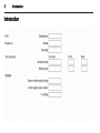
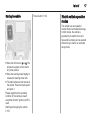
Vehicle specific data
Please enter your vehicle's data on
the previous page to keep it easily
accessible. This information is
available in the sections "Service and
maintenance" and "Technical data"
as well as on the identification plate.
Introduction
Your vehicle is a designed
combination of advanced technology,
safety, environmental friendliness
and economy.
The vehicle has two operation
modes: Electric and extended range.
In both modes, the vehicle is
propelled by its electric drive unit.
Thus, carbon dioxide emissions are
reduced considerably without losing
mobility and dynamics.
This Owner's Manual provides you
with all the necessary information to
enable you to drive your vehicle
safely and efficiently.
Just well trained technicians who are
aware of the manufacturer´s
instructions, are allowed to repair
and/or to work with high voltage
components.
Make sure your passengers are
aware of the possible risk of accident
and injury which may result from
improper use of the vehicle.
You must always comply with the
specific laws and regulations of the
country that you are in. These laws
may differ from the information in this
Owner's Manual.
When this Owner's Manual refers to a
workshop visit, we recommend your
Vauxhall Authorised Repairer.
All Vauxhall Authorised Repairers
provide first-class service at
reasonable prices. Experienced
mechanics trained by Vauxhall work
according to specific Vauxhall
instructions.
The customer literature pack should
always be kept ready to hand in the
vehicle.
3
Using this manual
■ This manual describes all options
and features available for this
model. Certain descriptions,
including those for display and
menu functions, may not apply to
your vehicle due to model variant,
country specifications, special
equipment or accessories.
■ The "In brief" section will give you
an initial overview.
■ The table of contents at the
beginning of this manual and within
each section shows where the
information is located.
■ The index will enable you to search
for specific information.
■ This Owner's Manual depicts lefthand drive vehicles. Operation is
similar for right-hand drive vehicles.
■ The Owner's Manual uses the
factory engine designations. The
corresponding sales designations
can be found in the section
"Technical data".
4
Introduction
■ Directional data, e.g. left or right, or
front or back, always relate to the
direction of travel.
■ The vehicle display screens may
not support your specific language.
■ Display messages and interior
labelling are written in bold letters.
Danger, Warnings and
Cautions
9 Danger
Text marked 9 Danger provides
information on risk of fatal injury.
Disregarding this information may
endanger life.
9 Warning
Text marked 9 Warning provides
information on risk of accident or
injury. Disregarding this
information may lead to injury.
Caution
Text marked Caution provides
information on possible damage to
the vehicle. Disregarding this
information may lead to vehicle
damage.
Symbols
Page references are indicated with 3.
3 means "see page".
Thank you for choosing a Vauxhall.
We wish you many hours of
pleasurable driving.
Your Vauxhall Team
Introduction
5
6
In brief
In brief
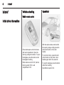
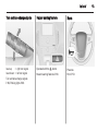
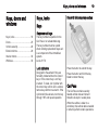
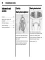
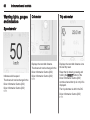
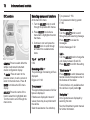
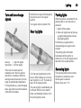
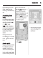
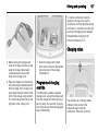
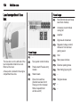
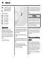
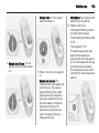
Vehicle unlocking
Open&Start
Radio remote control
Initial drive information
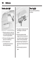
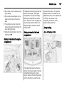
Press button ( to unlock the doors
and load compartment. Open the
doors by pulling the handles. To open
the tailgate, press the button under
the tailgate moulding.
Radio remote control 3 20, Central
locking system 3 23, Load
compartment 3 25.
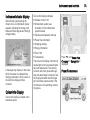
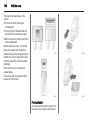
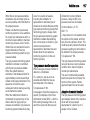
With the radio remote control within
the opening range, simply press the
lock/unlock button on the door
handle.
To unlock all doors, press the lock/
unlock button on the driver´s door
handle again within five seconds.
To open the tailgate, press the button
under the moulding.
Open&Start system 3 22.
In brief
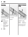
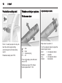
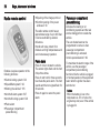
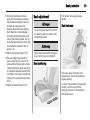
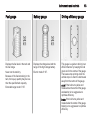
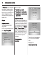
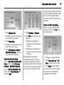
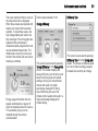
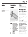
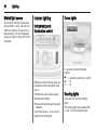
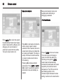
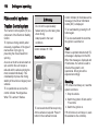
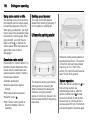
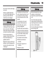
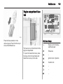
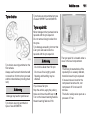
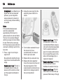
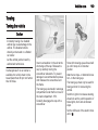
Seat adjustment
Seat backrests
Seat height
Pull lever, adjust inclination and
release lever. Allow the seat to
engage audibly.
Seat position 3 34, Seat adjustment
3 35.
Lever pumping motion:
up
= seat higher
down = seat lower
7
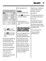
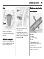
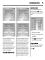
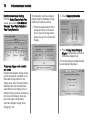
Seat positioning
Pull handle, slide seat, release
handle.
Seat position 3 34, Seat adjustment
3 35.
9 Danger
Do not sit nearer than 25 cm from
the steering wheel, to permit safe
airbag deployment.
Seat position 3 34, Seat adjustment
3 35.
8
In brief
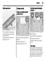
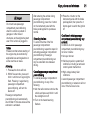
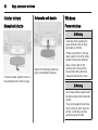
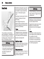
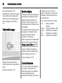
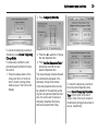
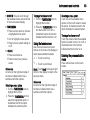
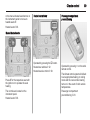
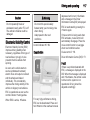
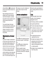
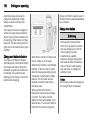
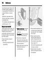
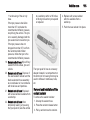
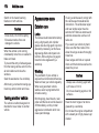
Head restraint adjustment
Seat belt
Mirror adjustment
Interior mirror
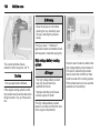
Press the button, adjust height and
engage.
Head restraints 3 33.
Pull out the seat belt and engage in
belt buckle. The seat belt must not be
twisted and must fit close against the
body. The backrest must not be tilted
back too far (maximum approx. 25 °).
To release belt, press red button on
belt buckle.
Seat position 3 34, Seat belts
3 38, Airbag system 3 41.
To reduce dazzle, adjust the lever on
the underside of the mirror housing.
Interior mirror 3 30, Automatic antidazzle interior mirror 3 30.
In brief
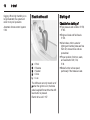
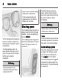
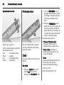
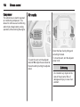
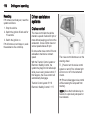
Exterior mirrors
Steering wheel adjustment
Select the relevant exterior mirror and
adjust.
Convex exterior mirrors 3 29,
Electric adjustment 3 29, Folding
exterior mirrors 3 29, Heated
exterior mirrors 3 29.
Unlock lever, adjust steering wheel,
then engage lever and ensure it is
fully locked.
Do not adjust steering wheel unless
vehicle is stationary and steering
wheel lock has been released.
Airbag system 3 41.
9
10
In brief
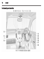
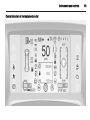
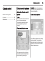
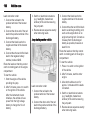
Instrument panel overview
In brief
1
2
Cruise control ...................... 118
Light switch ........................... 87
Turn and lane-change
signals ................................... 89
3
4
Pedestrian safety alert .......... 59
Horn ...................................... 59
Instrument cluster ................. 64
5
7
8
Driver Information Centre
(DIC) ..................................... 71
Steering wheel controls ........ 58
Centre air vents ................... 100
Dome lights ........................... 90
Reading lights ....................... 90
Ultrasonic park assist .......... 120
Anti-theft alarm system ......... 27
Electronic Stability Control . . 117
Traction Control System ..... 116
9
10 Charging status indicator .... 127
11 Light sensor .......................... 87
12
13
14
15
16
17
18
19
20
21
22
23
24
25
Seat belt reminder control ..... 66
26
Airbag deactivation control
indicator ................................ 67
Interior mirror ........................ 30
27
28
Climate sensor ...................... 93
Instrument panel storage ...... 51
Colour-Info-Display ............... 73
Side air vents ...................... 100
Glovebox ............................... 51
Central locking buttons ......... 23
Electrical parking brake ...... 113
Infotainment system (see
infotainment system manual)
Shift lever ............................ 111
Power button ....................... 103
Drive mode button .............. 108
Leaf button ............................ 73
Bonnet release lever ........... 138
Steering wheel adjustment . . . 58
Instrument panel
illumination control ................ 90
Charge port door release
button .................................. 124
Power windows ..................... 30
Fuel door release button ..... 133
11
29 DIC controls .......................... 71
30 Headlight range adjustment . . 88
12
In brief
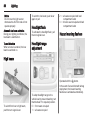
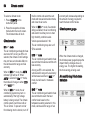
Exterior lighting
Headlight flash, high beam and
low beam
r = rear fog light
Turn adjuster wheel:
AUTO = automatic light control:
Exterior lighting is
switched on and off
automatically
m
= activation or deactivation
of the automatic light
control
= sidelights
8
= low beam
9
Lighting 3 87.
headlight flash = pull lever
high beam
= push lever
low beam
= push or pull lever
Automatic light control 3 87, High
beam 3 88, Headlight flash 3 88.
In brief
Turn and lane-change signals
Hazard warning flashers
Horn
lever up
= right turn signal
lever down = left turn signal
Operated with the ¨ button.
Hazard warning flashers 3 88.
Press j.
Horn 3 59.
Turn and lane-change signals
3 89, Parking lights 3 89.
13
14
In brief
Pedestrian safety alert
Washer and wiper systems
Adjustable wiper interval
Windscreen wiper
Push 4 to alert people who may not
hear the vehicle approaching.
A soft‐note alert will momentarily
sound.
Pedestrian safety alert 3 59.
2
1
5
§
=
=
=
=
fast
slow
interval wiping
off
For a single wipe, press the lever
down to Q.
Windscreen wiper 3 59, Wiper
blade replacement 3 144.
Wiper lever in position 5.
Turn the adjuster wheel to adjust the
desired wipe interval:
short
= turn adjuster wheel
interval
upwards
long
= turn adjuster wheel
interval
downwards
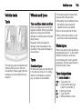
In brief
Windscreen washer
Climate control
Heated rear window, heated
exterior mirrors
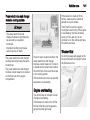
Pull lever. Washer fluid is sprayed
onto the windscreen and the wiper
wipes a few times.
Windscreen washer system 3 59,
Washer fluid 3 141.
Heating is operated by pressing the
Ü button.
Heated rear window 3 32.
Heated rearview mirror 3 29.
15
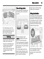
Demisting and defrosting the
windows
Press V button.
Set temperature to warmest level.
Heated rear window Ü on.
Automatic climate control system
3 93.
Auto defog
The system monitors high humidity
inside the vehicle. When detected,
the system may adjust to outside air
supply and turn on the air conditioning
or the heater. The fan speed may
slightly increase to help prevent
16
In brief
fogging. When high humidity is no
longer detected, the system will
return to its prior operation.
Automatic climate control system
3 93.
Electric drive unit
Starting off
Check before starting off
P
R
N
D
L
=
=
=
=
=
Park
Reverse
Neutral
Drive
Low
The shift lever can only moved out of
P when the ignition is on, the brake
pedal is applied first and then the shift
lever button is pressed.
Electric drive unit 3 107.
■ Tyre pressure and condition 3 156,
3 183.
■ Engine oil level and fluid levels
3 138.
■ All windows, mirrors, exterior
lighting and number plates are free
from dirt, snow and ice and are
operational.
■ Proper position of mirrors, seats,
and seat belts 3 29, 3 34,
3 39.
■ Brake function at low speed,
particularly if the brakes are wet.
In brief
Starting the vehicle
Power button 3 103.
17
Electric vehicle operation
modes
The vehicle has two operation
modes: Electric and extended range.
In both modes, the vehicle is
propelled by its electric drive unit.
Several drive modes can be selected
while driving in electric or extended
range mode:
■ Move the shift lever to P or N. The
propulsion system will not start in
any other position.
■ Move the steering wheel slightly to
release the steering wheel lock.
■ The radio remote control must be in
the vehicle. Press the brake pedal
and push m.
Please regard that the operating
condition of the vehicle is meant
everytime the term "ignition on/off" is
used.
Starting and stopping the vehicle
3 105.
18
In brief
Parking
Press DRIVE MODE button as often
as the desired drive mode is
highlighted.
The following drive modes are
selectable:
■ Normal
■ Sport
■ Mountain
■ Hold
Electric vehicle operation modes
3 107.
■ Do not park the vehicle on an easily
ignitable surface. Things that can
burn could touch hot exhaust parts
under the vehicle and ignite.
■ Always apply the parking brake.
Pull switch m.
■ Switch off the ignition. Turn the
steering wheel until the steering
wheel lock engages.
■ If the vehicle is on a level surface or
uphill slope, set the parking brake
and then shift the selector lever to
P, before switching off the ignition.
On an uphill slope, turn the front
wheels away from the kerb.
If the vehicle is on a downhill slope,
set the parking brake and then shift
the selector lever to P, before
switching off the ignition. Turn the
front wheels towards the kerb.
■ Lock the vehicle and activate the
anti-theft alarm system.
Radio remote control 3 20.
Anti-theft alarm system 3 27.
Keys, doors and windows
Keys, doors and
windows
Keys, locks ................................... 19
Doors ........................................... 25
Vehicle security ............................ 26
Exterior mirrors ............................ 29
Interior mirrors ............................. 30
Windows ...................................... 30
Keys, locks
19
Key with foldaway key section
Keys
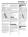
Replacement keys
The key number is specified in the
Car Pass or on a detachable tag.
The key number must be quoted
when ordering replacement keys as it
is a component of the immobiliser
system.
Locks 3 170.
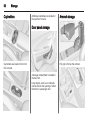
Lock cylinders
Designed to free-wheel if they are
forcefully rotated without the correct
key or if the correct key is not fully
inserted. To reset, turn cylinder with
the correct key until its slot is vertical,
remove key and then re-insert it. If the
cylinder still free-wheels, turn the key
through 180° and repeat operation.
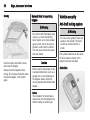
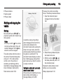
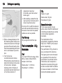
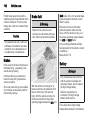
Press the button to extend the key.
Press the button and fold the key
blade to retract the key.
Car Pass
The Car Pass contains security
related vehicle data and should
therefore be kept in a safe place.
When the vehicle is taken to a
workshop, this vehicle data is needed
in order to perform certain operations.
20
Keys, doors and windows
Radio remote control
■ Opening of the charge port door
■ Comfort opening of the power
windows 3 30
The radio remote control has an
approximate range of up to 200 feet.
It can be restricted by external
influences.
Handle with care, protect from
moisture and high temperatures and
avoid unnecessary operation.
Panic alarm
Enables a keyless operation of the
following functions:
■ Central locking system 3 23
■ Open&Start system 3 22
■ Starting the vehicle 3 105
■ Anti-theft alarm system 3 27
■ Anti-theft locking system 3 26
■ Panic alarm
■ Passenger compartment
preconditioning
Press ! once to locate the vehicle.
The exterior lights flash and the horn
chirps three times.
Press ! and hold for three seconds
to activate the panic alarm. The horn
sounds and the turn signals flash for
30 seconds.
Press ! again to cancel the panic
alarm.
Passenger compartment
preconditioning
Activates the heating or air
conditioning systems and the rear
window defogger from outside the
vehicle.
The auto heated seat can be
programmed to come on when
passenger compartment
preconditioning is activated.
Vehicle personalisation 3 82.
To maximise the electric range of the
vehicle, use the passenger
compartment preconditioning
function while the vehicle is plugged
in. Normal operation of the system will
return after the ignition has been
switched on.
Notice
When the battery is low or the
temperature is -4°C or below, the
engine may start, even if the vehicle
is plugged in.
Keys, doors and windows
9 Danger
Do not activate passenger
compartment preconditioning
when the vehicle is parked in
garages or other closed
structures, as the engine may start
even if the vehicle is plugged in.
Notice
Please note that remote starting of
the engine may be restricted by
applicable laws and regulations in
some countries or areas.
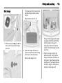
Activating
1. Press ); the doors will lock.
2. Within five seconds, press and
hold # until the turn signal lights
flash. Pressing # again during
passenger compartment
preconditioning, will turn the
feature off.
Passenger compartment
preconditioning will automatically
shut off after 10 minutes unless a time
extension is activated.
After entering the vehicle during
passenger compartment
preconditioning, press the m button
on the instrument panel with the
brake pedal applied to operate as
normal.
Extending the time
To extend the time of the first
passenger compartment
preconditioning, repeat the steps for
activating passenger compartment
preconditioning. Passenger
compartment preconditioning can
only be extended once between
driving.
Cancelling passenger compartment
preconditioning
To cancel passenger compartment
preconditioning, do any of the
following:
■ Aim the radio remote control at the
vehicle and press and hold # until
the sidelights turn off.
■ Turn on the hazard warning
flashers.
21
■ Press the m button on the
instrument panel with the brake
pedal applied, then press the m
button again to switch the ignition
off.
Conditions in which passenger
compartment preconditioning may
not work
Conditions in which passenger
compartment preconditioning may
not occur include:
■ An open bonnet.
■ Vehicle propulsion system fault
conditions, including an emission
control system malfunction.
■ High voltage battery fault
conditions.
A second passenger compartment
preconditioning or extension will not
occur if the fuel level is low.
22
Keys, doors and windows
Conditions in which passenger
compartment preconditioning may be
cancelled include:
■ Vehicle propulsion system or high
voltage battery fault conditions.
■ Low engine oil pressure.
■ Engine coolant temperature that is
too high.
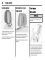
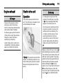
Charge port door
Press $ to open the charge port
door.
Charging 3 124.
Fault in the radio remote control
system
In the event that it is not possible to
operate the radio remote control
properly, it may be due to the
following:
■ Range exceeded
■ Battery voltage too low
■ Blocked signal
If the problem persists, seek the
assistance of your workshop.
Keep in mind that other conditions,
such as those stated, can impact the
performance of the radio remote
control.
Unlocking 3 23.
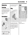
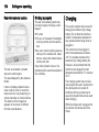
Radio remote control battery
replacement
Notice
When replacing the battery, do not
touch any of the circuitry on the
transmitter. Static from your body
could damage the transmitter.
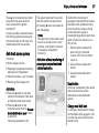
Replace the battery as soon as the
range reduces.
Extend the key and open the unit.
Replace the battery (battery type CR
2032), paying attention to the
installation position. Close the unit
and check the operation of the radio
remote control.
Batteries do not belong in household
waste. They must be disposed of at
an appropriate recycling collection
point.
Open&Start system
A transponder within the radio remote
control enables a passive locking and
unlocking of the doors and the
tailgate.
Furthermore the Open&Start system
enables the starting of the vehicle.
Starting and stopping the vehicle
3 105.
Keys, doors and windows
The radio remote control should be
within three feet of the door or the
tailgate being opened.
Unlocking
and the tailgate, press lock/unlock
button on the driver's door again
within five seconds.
Vehicle personalisation 3 82.
23
Unlocking
Locking
To lock the doors and the tailgate,
press the lock/unlock button on any of
the door handles if all doors are
closed.
Central locking system
Unlocks and locks doors and the
tailgate.
Two settings are selectable:
■ To unlock all doors and the tailgate,
press lock/unlock button on any of
the door handles once
or
■ press the lock/unlock button on the
driver's door once to unlock only the
driver's door. To unlock all doors
Notice
In the event of an accident in which
airbags or belt pretensioners are
deployed, the vehicle is
automatically unlocked.
Press ( button.
Two settings are selectable:
■ To unlock all doors and the tailgate,
press button ( once
or
■ press button ( once to unlock only
the driver's door. To unlock all
doors and the tailgate, press button
( twice within five seconds.
Power windows 3 30.
Vehicle personalisation 3 82.
24
Keys, doors and windows
The hazard warning flashers will flash
twice each time the button is pressed
and the anti-theft alarm system will be
disarmed.
Anti-theft alarm system 3 27.
Locking
Close doors, tailgate, fuel filler cap.
Press button ).
The hazard warning flashers will flash
once and the anti-theft alarm system
will be armed.
Anti-theft alarm system 3 27.
If the driver's door is open when ) is
pressed, all doors lock and then the
driver's door will unlock if the Prevent
doorlock while door open feature is
enabled through the vehicle
personalisation.
Vehicle personalisation 3 82.
By pressing ) twice within five
seconds with all doors closed and the
igition switched off, all doors will be
locked and the anti-theft locking
system will be activated.
Anti-theft locking system 3 26.
Locks or unlocks all doors.
Press the ) button to lock.
Press the ( button to unlock.
Central locking buttons
Fault in the central locking
system
Lockout protection
If the ) button on the instrument
panel is pressed when the driver's
door is open and the ignition is on, all
doors will lock and the driver's door
will unlock.
This feature can also be enabled
when the ignition is off.
Vehicle personalisation 3 82.
Unlocking
Manually unlock the driver's door by
turning the key in the lock. The other
doors can be opened by pulling the
interior handle twice. The tailgate
cannot be opened. To deactivate the
anti-theft locking system, switch on
the ignition 3 27.
Keys, doors and windows
Locking
Push inside locking knob of all doors
except driver's door. Then close the
driver's door and lock it from the
outside with the key. The tailgate
cannot be locked.
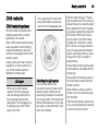
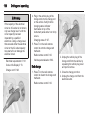
Child locks
9 Warning
Use the child locks whenever
children are occupying the rear
seats.
Press H% to activate. The LED
comes on.
Press H% again to deactivate. The
LED goes out.
The rear doors cannot be opened
from the inside.
25
Doors
Load compartment
Tailgate
Opening
To open the tailgate with the doors
unlocked, press the button on the
underside of the tailgate handle and
lift up.
If the doors are locked, it is necessary
to open the tailgate with the radio
remote control within the opening
range.
26
Keys, doors and windows
Closing
General hints for operating
tailgate
9 Warning
Do not drive with the tailgate open
or ajar, e.g. when transporting
bulky objects, since toxic exhaust
gases, which can not be seen or
smelled, could enter the vehicle.
This can cause unconsciousness
and even death.
Use the inside pull handle to lower
and close the tailgate.
Always close the tailgate before
driving. Do not press the button while
closing the tailgate, it will unlatch
again.
Caution
Before opening the tailgate, check
overhead obstructions, such as a
garage door, to avoid damage to
the tailgate. Always check the
moving area above and behind the
tailgate.
Notice
The installation of certain heavy
accessories onto the tailgate may
affect its ability to remain open.
Vehicle security
Anti-theft locking system
9 Warning
Do not use the system if there are
people in the vehicle! The doors
cannot be unlocked from the
inside.
The system deadlocks all the doors.
All doors must be closed or the
system cannot be activated.
Activation
Keys, doors and windows
Press ) on the radio remote control
twice within five seconds with all
doors closed and the ignition
switched off.
It is also possible to activate the antitheft locking system by pressing the
lock/unlock button on the driver door
handle twice within five seconds.
Anti-theft alarm system
It monitors:
■ Doors, tailgate, bonnet
■ Passenger compartment including
adjoining load compartment
■ Vehicle inclination, e.g. if it is raised
■ Removing of the charge cord
Activation
■ Press the ) button on the radio
remote control after all of the doors
and windows have been closed.
■ Press the ) button on the
instrument panel when the Prevent
doorlock while door open function
is turned off.
Vehicle personalisation 3 82.
The system arms itself 30 seconds
after the vehicle has been locked.
By pressing ) twice, the system will
arm immediately.
Notice
Changes to the vehicle interior such
as the use of seat covers or open
windows, could impair the function
of passenger compartment
monitoring.
Activation without monitoring of
passenger compartment and
vehicle inclination
27
Switch off the monitoring of
passenger compartment and vehicle
inclination when animals are being
left in the vehicle, because of high
volume ultrasonic signals or
movements triggering the alarm. Also
switch off when the vehicle is on a
ferry or train.
1. With the ignition switched off,
press o in the overhead
console. LED in the o button
comes on.
2. Close all doors, tailgate and
bonnet.
3. Activate the anti-theft alarm
system.
Deactivation
Unlocking or approaching the vehicle
with the radio remote control,
deactivates the anti-theft alarm
system.
Charge cord theft alert
To activate or deactivate the charge
cord theft alert while plugged in, lock
or unlock the vehicle with the radio
remote control.
28
Keys, doors and windows
If there is an attempt to remove the
charge cord while the vehicle is
locked, the system alarm will be
activated. To turn off the system
alarm, press ( on the radio remote
control.
This function can be disabled in
vehicle personalisation.
Vehicle personalisation 3 82.
To turn off the system alarm:
■ Press ( on the radio remote control
or
■ Start the vehicle by pressing the m
button on the instrument panel with
the brake pedal applied and the
radio remote control located inside
the vehicle.
d comes on if there is a problem with
activating or deactivating the
immobiliser.
Alarm
Immobiliser
If the vehicle does not start and the
control indicator stays on, there is a
problem with the system. Attempt to
switch the ignition off and try it again.
If the problem presists, seek the
assistance of a workshop.
Do not leave the radio remote control
inside the vehicle.
Control indicator d 3 70.
When triggered, the alarm sounds via
a separate battery-backed power
sounder for about 30 seconds and the
hazard warning lights flash
simultaneously.
If the vehicle loses battery power
when the anti-theft alarm system is
armed, the power sounder will
activate automatically.
The number and duration of alarm
signals are stipulated by legislation.
This vehicle has a passive theftdeterrent system. The system does
not have to be manually activated or
deactivated.
The immobiliser is activated
automatically after the ignition is
switched off.
The system is automatically disarmed
when the vehicle is started with a valid
radio remote control located inside
the vehicle. The radio remote control
uses electronic coding that matches
an immobiliser control unit in the
vehicle and automatically deactivates
the system. Only a correct radio
remote control can be used to switch
the ignition on.
Notice
The immobiliser does not lock the
doors. You should always lock the
vehicle after leaving it and switch on
the anti-theft alarm system 3 23,
3 27.
Keys, doors and windows
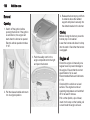
Exterior mirrors
Convex shape
The convex exterior mirror contains
an aspherical area and reduces blind
spots. The shape of the mirror makes
objects appear smaller, which will
affect the ability to estimate
distances.
In the centre position of the selector
switch no mirror is selected.
29
Heated
Folding
Electric adjustment
For pedestrian safety, the exterior
mirrors will swing out of their normal
mounting position if they are struck
with sufficient force. Reposition the
mirror by applying slight pressure to
the mirror housing.
Select the relevant exterior mirror by
moving the selector switch to left (L)
or right (R). Then press the control
pad to adjust the respective mirror.
Operated by pressing the Ü button.
Turns off automatically after about
five minutes.
Heated rear window 3 32.
30
Keys, doors and windows
Interior mirrors
Automatic anti-dazzle
Manual anti-dazzle
Windows
Power windows
9 Warning
To reduce dazzle, adjust the lever on
the underside of the mirror housing.
Dazzle from following vehicles at
night is automatically reduced.
Take care when operating the
power windows. Risk of injury,
particularly to children.
If there are children on the rear
seats, switch on the child safety
system for the power windows.
Keep a close watch on the
windows when closing them.
Ensure that nothing becomes
trapped in them as they move.
9 Warning
Do not leave children together with
the radio remote control inside the
vehicle.
They could operate the windows ,
other controls or even move the
vehicle, so that they could be
seriously injured or killed.
Keys, doors and windows
Switch on ignition to operate the
power windows.
The driver window can be lowered or
raised without holding the switch.
The passenger and rear windows can
just be lowered without holding the
switch.
Power windows can work until the
driver's door is opened or at the latest
for 10 minutes after the ignition is
switched off.
Retained power off 3 104.
31
Child safety system for rear
windows
Safety function
Operate the switch for the respective
window by pushing to open or pulling
to close.
Pushing or pulling gently to the first
detent: window moves up or down as
long as the switch is operated.
Pushing or pulling firmly to the second
detent and then releasing: window
moves up or down automatically with
safety function enabled. To stop
movement, operate the switch once
more in the same direction.
If the window glass encounters
resistance above the middle of the
window during automatic closing, it is
immediately stopped and opened
again.
Override safety function
In the event of closing difficulties due
to frost or the like, pull and hold the
switch. The window moves up without
safety function. To stop movement,
release the switch.
Use care when using the override
safety function.
Press switch H% to deactivate rear
door power windows, the LED
illuminates.
Press H% again to deactivate.
Operating windows from the
outside
The windows can be opened
remotely from outside the vehicle.
32
Keys, doors and windows
Activate the window electronics as
follows:
1. Close all doors with the ignition on
or when retained power off is
active.
2. Pull switch until the window is
closed and keep pulling for
additional 2 seconds.
3. Repeat for each window.
Press and hold ( button to open
windows.
Release button to stop window
movement.
Heated rear window
Pull the sun visor down to block glare.
Detach the sun visor from the centre
mount to pivot to the side window or
to extend along the rod.
If the sun visors have integral mirrors,
the mirror covers should be closed
when driving.
Overload
If the windows are repeatedly
operated within short intervals, the
window operation is disabled for
some time.
Initialising the power windows
Initialise the power windows may be
necessary if the 12 volt battery has
been disconnected or discharged.
Sun visors
Operated by pressing the Ü button.
Heating turns off automatically after
about five minutes.
Seats, restraints
Seats, restraints
Head restraints ............................ 33
Front seats ................................... 34
Seat belts ..................................... 38
Airbag system .............................. 41
Child restraints ............................. 45
Head restraints
33
Adjustment
Head restraints on front seats
Position
Height adjustment
9 Warning
Only drive with the head restraint
set to the proper position.
Press the button, adjust height and
make sure that the head restraint is
engaged.
The upper edge of the head restraint
should be at upper head level. If this
is not possible for extremely tall
people, set to highest position, and
set to lowest position for small people.
34
Seats, restraints
Inclination adjustment
Head restraints on rear seats
Front seats
Height adjustment
Seat position
9 Warning
Only drive with the seat correctly
adjusted.
To adjust horizontally, pull the head
restraint forwards. It engages in
several positions.
To return to its rearmost position, pull
fully forwards and release.
Pull the head restraint upwards or
press the catch to release and push
the head restraint downwards.
Make sure that the head restraint is
engaged.
■ Sit with buttocks as far back against
the backrest as possible. Adjust the
distance between the seat and the
pedals so that legs are slightly
angled when pressing the pedals.
Slide the front passenger seat as
far back as possible.
Seats, restraints
■ Sit with shoulders as far back
against the backrest as possible.
Set the backrest rake so that it is
possible to easily reach the
steering wheel with arms slightly
bent. Maintain contact between
shoulders and the backrest when
turning the steering wheel. Do not
angle the backrest too far back. We
recommend a maximum rake of
approx. 25°.
■ Adjust the steering wheel 3 58.
■ Set seat height high enough to
have a clear field of vision on all
sides and of all display instruments.
There should be at least one hand
of clearance between head and the
roof frame. Your thighs should rest
lightly on the seat without pressing
into it.
■ Adjust the head restraint 3 33.
Seat adjustment
9 Danger
35
Pull handle, slide seat, release
handle.
Seat backrests
Do not sit nearer than 25 cm from
the steering wheel, to permit safe
airbag deployment.
9 Warning
Never adjust seats while driving as
they could move uncontrollably.
Seat positioning
Pull lever, adjust inclination and
release lever. Allow the backrest to
engage audibly.
To return the seatback to the upright
position, pull the lever without
applying pressure to the seatback
and release lever.
36
Seats, restraints
Seat height
Lever pumping motion:
up
= seat higher
down = seat lower
Heating
Auto heated seats
Manual heated seats
Activation
To activate auto heated seats:
Adjust heating to the desired setting
by pressing the ß button for the
respective seat one or more times.
The LEDs next to the heating symbol
indicate the setting.
Prolonged use of the highest setting
for people with sensitive skin is not
recommended.
1. Press the Climate control button
on the instrument panel.
Seats, restraints
Vehicle personalisation 3 82.
Deactivation
To deactivate auto heated seats:
■ Press ß AUTO on the touch screen
of the Colour-Info-Display
or
■ Press the ß button for the
respective seat on the instrument
panel.
2. Press ß AUTO on the touch
screen of the Colour-Info-Display.
The ß AUTO button illuminates
green as a confirmation of the
setting.
When the ignition is switched on, the
auto heated seats function will
automatically activate the heated
seats at the level required by the
vehicle's interior temperature.
The LEDs next to the seat heating
symbol on the instrument panel
indicate the heat setting.
Auto heated seats can be
programmed to always be enabled
when the ignition is on.
Heated seats during passenger
compartment preconditioning
When it is cold outside, the heated
seats can be programmed to turn on
automatically during passenger
compartment preconditioning. Unless
the auto heated seats function is
available and enabled, the heated
seats will be cancelled when the
ignition is switched on. If the auto
heated seats function is enabled, the
seat heating level will automatically
change to the level required by the
vehicle's interior temperature when
the ignition is switched on.
37
The LEDs next to the seat heating
symbol do not turn on during
passenger compartment
preconditioning.
The temperature performance of an
unoccupied seat may be reduced.
This is normal.
The heated seats will not turn on
during passenger compartment
preconditioning unless the heated
seats feature is enabled in the vehicle
personalisation menu.
Vehicle personalisation 3 82.
Passenger compartment
preconditioning 3 20.
38
Seats, restraints
Seat belts
The seat belts are locked during
heavy acceleration or deceleration of
the vehicle holding the occupants in
the sitting position. Thereby the risk of
injury is considerably reduced.
9 Warning
Fasten seat belt before each trip.
In the event of an accident, people
not wearing seat belts endanger
their fellow occupants and
themselves.
Seat belts are designed to be used by
only one person at a time. They are
not suitable for people smaller than
150 cm. Child restraint system
3 45.
Periodically check all parts of the belt
system for damage and proper
functionality.
Have damaged components
replaced. After an accident, have the
belts and triggered belt pretensioners
replaced by a workshop.
Notice
Make sure that the belts are not
damaged by shoes or sharp-edged
objects or are trapped. Prevent dirt
from getting into the belt retractors.
Seat belt reminder X 3 66.
Belt force limiters
On the front seats, stress on the body
is reduced by the gradual release of
the belt during a collision.
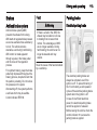
Belt pretensioners
In the event of a head-on or rear-end
collision of a certain severity, the front
seat belts are tightened.
9 Warning
Incorrect handling (e.g. removal or
fitting of belts) can trigger the belt
pretensioners.
Deployment of the belt pretensioners
is indicated by continuous illumination
of control indicator v 3 66.
Triggered belt pretensioners must be
replaced by a workshop. Belt
pretensioners can only be triggered
once.
Notice
Do not affix or install accessories or
other objects that may interfere with
the operation of the belt
pretensioners. Do not make any
modifications to belt pretensioner
components as this will invalidate
the vehicle type approval.
Seats, restraints
Three-point seat belt
39
Removing
Fastening
Withdraw the belt from the retractor,
guide it untwisted across the body
and insert the latch plate into the
buckle. Tighten the lap belt regularly
whilst driving by pulling the shoulder
belt. Seat belt reminder 3 66.
Loose or bulky clothing prevents the
belt from fitting snugly. Do not place
objects such as handbags or mobile
phones between the belt and your
body.
9 Warning
The belt must not rest against hard
or fragile objects in the pockets of
your clothing.
To release belt, press red button on
belt buckle.
Seat belt comfort guides on the
rear seats
The guides may provide added seat
belt comfort for older children who
have outgrown booster seats and for
some adults. When installed and
properly adjusted, the comfort guide
positions the seat belt away from the
neck and head.
40
Seats, restraints
There is one guide for each rear seat.
When using a comfort guide, remove
the seat belt from the seat‐mounted
guide before using the comfort guide.
Installation:
1. Remove the guide from its
storage clip on the interior body
trim next to the rear seat.
and across the chest. These parts
of the body are best able to take
belt restraining forces.
2. Place the guide over the belt, and
insert the two edges of the seat
belt into the slots of the guide.
3. The seat belt should not be
twisted and it should lie flat. The
elastic cord must be under the
seat belt and the guide on top.
9 Warning
A seat belt that is not properly
worn may not provide the
protection needed in a crash. The
person wearing the seat belt could
be seriously injured. The shoulder
belt should go over the shoulder
4. Buckle and position the seat belt
as described previously in this
section. Make sure that the
shoulder belt crosses the
shoulder.
5. To remove and store the comfort
guide, squeeze the seat belt
edges together so that the seat
belt can be removed from the
guide. Slide the guide back into its
storage clip.
Seats, restraints
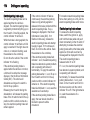
Using the seat belt while
pregnant
Airbag system
The airbag system consists of a
number of individual systems
depending on the scope of
equipment.
When triggered the airbags inflate
within milliseconds. They also deflate
so quickly that it is often unnoticeable
during the collision.
9 Warning
9 Warning
The lap belt must be positioned as
low as possible across the pelvis
to prevent pressure on the
abdomen.
If handled improperly the airbag
systems can be triggered in an
explosive manner.
Notice
The airbag systems and belt
pretensioner control electronics are
located in the centre console area.
Do not put any magnetic objects in
this area.
Do not stick anything on the airbag
covers and do not cover them with
other materials.
41
Each airbag is triggered only once.
Have deployed airbags replaced by
a workshop. Furthermore, it might be
necessary to have the steering
wheel, the instrument panel, parts of
the panelling, the door seals,
handles and the seats replaced.
Do not make any modifications to
the airbag system as this will
invalidate the vehicle type approval.
When the airbags inflate, escaping
hot gases may cause burns.
Control indicator v for airbag systems
3 66.
Front airbag system
The front airbag system consists of
one airbag in the steering wheel and
one in the instrument panel on the
front passenger side. These can be
identified by the word AIRBAG.
42
Seats, restraints
Keep the area in which the airbag
inflates clear of obstructions.
Fit the seat belt correctly and
engage securely. Only then the
airbag is able to protect.
Side airbag system
The front airbag system is triggered in
the event of a front-end impact of a
certain severity. The ignition needs to
be switched on.
The inflated airbags cushion the
impact, thereby reducing the risk of
injury to the upper body and head of
the front seat occupants
considerably.
9 Warning
Optimum protection is only
provided when the seat is in the
proper position 3 34.
The side airbag system consists of an
airbag in each side of the front seat
backrests. This can be identified by
the word AIRBAG.
The side airbag system is triggered in
the event of a side impact of a certain
severity. The ignition needs to be
switched on.
The inflated airbags cushion the
impact, thereby reducing the risk of
injury to the upper body and pelvis in
the event of a side-on collision
considerably.
9 Warning
Keep the area in which the airbag
inflates clear of obstructions.
Notice
Only use protective seat covers that
have been approved for the vehicle.
Be careful not to cover the airbags.
Curtain airbag system
The curtain airbag system consists of
an airbag in the roof frame on each
side. This can be identified by the
word AIRBAG on the roof pillars.
The curtain airbag system is triggered
in the event of a side-on impact of a
certain severity. The ignition needs to
be switched on.
Seats, restraints
Knee airbag system
The knee airbags are located below
the steering column and below the
glovebox.
43
Keep the area in which the airbag
inflates clear of obstructions.
Airbag deactivation
Front airbag and knee airbag systems
for the front passenger seat must be
deactivated if a child restraint system
is to be fitted on this seat. The curtain
and side airbag systems, the belt
pretensioners and all driver airbag
systems will remain active.
The inflated airbags cushion the
impact, thereby reducing the risk of
injury to the head in the event of a
side-on impact considerably.
9 Warning
Keep the area in which the airbag
inflates clear of obstructions.
The hooks on the handles in the
roof frame are only suitable for
hanging up light articles of
clothing, without coat hangers. Do
not keep any items in these
clothes.
With knee airbags, the word
AIRBAG will appear on the lower
portion of the instrument panel.
The knee airbag system is triggered
in the event of a front-end impact of a
certain severity. The ignition needs to
be switched on.
The inflated airbags cushion the
impact, thereby reducing the risk of
injury to the lower body of the front
seat occupants considerably.
The front passenger airbag system
can be deactivated via a keyoperated switch located inside the
glovebox.
44
Seats, restraints
Use the ignition key to choose the
position:
W: Front passenger frontal and knee
airbags are deactivated and will not
inflate in the event of a collision.
Control indicator W illuminates
continuously. A child restraint system
can be installed in accordance with
the chart child restraint installation
locations 3 47. No adult person is
allowed to occupy the front
passenger seat.
V: Front passenger frontal and knee
airbags are active. A child restraint
system must not be installed.
9 Danger
Risk of fatal injury for a child using
a child restraint system on a seat
with activated front passenger
frontal and knee airbag.
Risk of fatal injury for an adult
person on a seat with deactivated
front passenger frontal and knee
airbag.
Control indicator for airbag
deactivation 3 67.
As long as the control indicator W is
not illuminated, the airbag systems
for the front passenger seat will inflate
in the event of a collision.
If both control indicators are
illuminated at the same time, there is
a system failure. The status of the
system is not discernible, therefore
no person is allowed to occupy the
front passenger seat. Contact a
workshop immediately.
Consult a workshop immediately if
neither of the two control indicators is
illuminated.
Change status only when the vehicle
is stopped with the ignition off.
Seats, restraints
Child restraints
Child restraint systems
This is especially the case if rearfacing child restraint systems are
used on the front passenger seat.
We recommend the Vauxhall child
restraint system which is tailored
specifically to the vehicle.
When a child restraint system is being
used, pay attention to the following
usage and installation instructions
and also those supplied with the child
restraint system.
Always comply with local or national
regulations. In some countries, the
use of child restraint systems is
forbidden on certain seats.
9 Danger
When using a child restraint
system on the front passenger
seat, the airbag systems for the
front passenger seat must be
deactivated; if not, the triggering of
the airbags poses a risk of fatal
injury to the child.
Selecting the right system
The rear seats are the most
convenient location to fasten a child
restraint system. Children should
travel facing rearwards in the vehicle
as long as possible. This makes sure
that the child's backbone, which is still
very weak, is under less strain in the
event of an accident.
45
Children under the age of 12 years
that are smaller than 150 cm are only
allowed to travel in a restraint system
that is suitable for the child. Suitable
are restraint systems that comply with
ECE 44-03 or ECE 44-04. Since a
proper position of the belt is rarely
possible with a child that is smaller
than 150 cm, we strongly advise the
use of an appropriate child restraint
system, even though this may, due to
the age of the child, no longer be
legally binding.
Ensure that the child restraint system
to be installed is compatible with the
vehicle type.
Ensure that the mounting location of
the child restraint system within the
vehicle is correct.
Allow children to enter and exit the
vehicle only on the side facing away
from the traffic.
When the child restraint system is not
in use, secure the seat with a seat belt
or remove it from the vehicle.
46
Seats, restraints
Notice
Do not stick anything on the child
restraint systems and do not cover
them with any other materials.
A child restraint system which has
been subjected to stress in an
accident must be replaced.
Seats, restraints
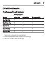
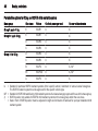
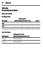
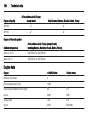
Child restraint installation locations
Permissible options for fitting a child restraint system
On front passenger seat
Mass group
activated airbag
deactivated airbag
On rear outboard seats
Group 0: Up to 10 kg
X
U1
U
Group 0+: Up to 13 kg
X
U1
U
Group I: 9 to 18 kg
X
U1
U
Group II: 15 to 25 kg
X
X
U
Group III: 22 to 36 kg
X
X
U
= Seating position must be adjusted to full up seat height travel.
U = Suitable for universal category restraints approved for use in this mass group.
X = Seat position not suitable for children in this mass group.
1
47
48
Seats, restraints
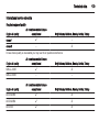
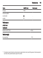
Permissible options for fitting an ISOFIX child restraint system
Mass group
Size class
Fixture
On front passenger seat
On rear outboard seats
Group 0: up to 10 kg
E
ISO/R1
X
IL1
Group 0+: up to 13 kg
E
ISO/R1
X
IL1
D
ISO/R2
X
IL1
C
ISO/R3
X
IL1
D
ISO/R2
X
IL1
C
ISO/R3
X
IL1
B
ISO/F2
X
IL, IUF
B1
ISO/F2X
X
IL, IUF
A
ISO/F3
X
IL
Group I: 9 to 18 kg
IL
= Suitable for particular ISOFIX restraint systems of the 'specific-vehicle', 'restricted' or 'semi-universal' categories.
The ISOFIX restraint system must be approved for the specific vehicle type.
IUF = Suitable for ISOFIX forward-facing child restraint systems of universal category approved for use in this mass group.
X
= ISOFIX position not suitable for ISOFIX child restraint systems in this mass group and/or the size class.
1
= Seat in front of ISOFIX position must be adjusted in length and inclination of backrest for a proper installation child
restraint system.
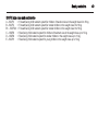
Seats, restraints
ISOFIX size class and seat device
A – ISO/F3
B – ISO/F2
B1 – ISO/F2X
C – ISO/R3
D – ISO/R2
E – ISO/R1
=
=
=
=
=
=
Forward-facing child restraint system for children of maximum size in the weight class 9 to 18 kg.
Forward-facing child restraint system for smaller children in the weight class 9 to 18 kg.
Forward-facing child restraint system for smaller children in the weight class 9 to 18 kg.
Rear-facing child restraint system for children of maximum size in the weight class up to 13 kg.
Rear-facing child restraint system for smaller children in the weight class up to 13 kg.
Rear-facing child restraint system for young children in the weight class up to 13 kg.
49
50
Seats, restraints
ISOFIX child restraint
systems
Fasten vehicle-approved ISOFIX
child restraint systems to the ISOFIX
mounting brackets.
ISOFIX mounting brackets are
indicated by a label & on the
backrest.
Top-tether fastening eyes
The Top-tether anchors for outboard
rear seating positions are on the back
of the rear seatback. Be sure to use
an anchor on the same side of the
vehicle as the seating position where
the child restraint will be placed.
Top-tether fastening eyes are marked
with the symbol : for a child seat.
In addition to the ISOFIX mounting,
fasten the Top-tether strap to the
Top-tether fastening eyes. The strap
must run between the two guide posts
of the head restraint.
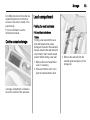
Storage
Storage
Storage compartments
51
Glovebox
Instrument panel storage
Storage compartments ................ 51
Load compartment ....................... 53
Loading information ..................... 56
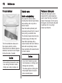
A storage compartment is located on
top of the instrument panel.
A transmitter slot for the radio remote
control transmitter is located inside
the storage compartment.
Radio remote control 3 20.
Starting and stopping the vehicle
3 105.
Open the glove box by lifting up on the
lever.
The glovebox should be closed whilst
driving.
52
Storage
Cupholders
Additional cupholders are located in
the rear floor console.
Armrest storage
Door panel storage
Pull grip to fold up the armrest.
Cupholders are located in the front
floor console.
A storage compartment is located in
the door trim.
Long objects, such as an umbrella,
can be slid into the opening of either
the driver or passenger door.
Storage
An USB port and an AUX socket are
located inside the front of the floor
console. Cords can be routed in the
pass-through.
For more information, see the
infotainment manual.
Centre console storage
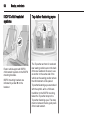
Load compartment
Folding the seat backrests
Fold seat backrests down
Notice
Folding a rear seat with the seat
belts still fastened may cause
damage to the seat or the seat belts.
Always unbuckle the seat belts and
return them to their normal stowed
position before folding a rear seat.
1. Remove the load compartment
cover, if necessary.
2. Press and hold the catch, then
push the head restraints down.
A storage compartment is located in
the centre console of the rear seats.
53
3. Remove the seat belt from the
seat belt guide and place it in the
storage clip.
54
Storage
If the seat belt is damaged, seek the
assistance of a workshop and have
it replaced.
9 Warning
Only drive the vehicle when the
backrests are securely locked into
position. Otherwise there is a risk
of personal injury or damage to the
load or vehicle in the event of
heavy braking or a collision.
4. Pull the seatback release lever to
unlock the seatback and fold the
seatback forward.
Fold seat backrests up
Notice
Damage to the seat belt or seat
backrest locking mechanism can
occur if the seat belt is caught
between the rear seat backrest and
the seat backrest locking
mechanism. The seat belt must be
out of the way when the rear seat is
raised to the upright, locked position.
1. Pull the seat belt gently out of the
storage clip and hold it in this
position.
2. Raise the seat backrest and push
it rearward to lock it into place.
Ensure that the seat backrest is
audibly engaged.
3. Return the seat belt to the seat
belt guide after raising the seat
backrest.
Keep the seat in the upright, locked
position when not in use.
Storage
55
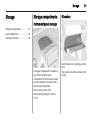
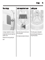
Rear storage
Load compartment cover
Lashing eyes
A storage compartment is located in
the right side of the load compartment
behind a cover.
Remove the cover by pushing the
latch.
Use the four loops to hook the cover
to the side panels.
Do not place any objects on the cover.
The lashing eyes are designed to
secure items against slippage, e.g.
using lashing straps.
56
Storage
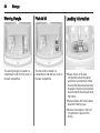
Warning triangle
First aid kit
The warning triangle is located in a
compartment under the floor cover in
the load compartment.
The first aid kit is located in a
compartment under the floor cover in
the load compartment.
Loading information
■ Heavy objects in the load
compartment should be placed
against the seat backrests. Make
sure that the backrests are securely
engaged. If objects can be stacked,
heavier objects should be placed at
the bottom.
■ Secure objects with lashing straps
attached to lashing eyes.
■ Secure loose objects in the load
compartment to prevent from
sliding.
Storage
■ When transporting objects in the
load compartment, the backrests of
the rear seats must not be angled
forward.
■ Do not allow the load to protrude
above the upper edge of the
backrests.
■ Do not place any objects on the
load compartment cover or the
instrument panel, and do not cover
the sensor on top of the instrument
panel.
■ The load must not obstruct the
operation of the pedals, shift lever,
or hinder the freedom of movement
of the driver. Do not place any
unsecured objects in the interior.
■ Do not drive with an open load
compartment.
9 Warning
Always make sure that the load in
the vehicle is securely stowed.
Otherwise objects can be thrown
around inside the vehicle and
cause personal injury or damage
to the load or car.
■ The payload is the difference
between the permitted gross
vehicle weight and the EC kerb
weight.
To calculate the payload, enter the
data for your vehicle in the weights
table at the front of this manual.
The EC kerb weight includes
weights for the driver (68 kg),
luggage (7 kg) and all fluids (tank
90 % full).
Optional equipment and
accessories increase the kerb
weight.
57
58
Instruments and controls
Instruments and
controls
Controls
Steering wheel controls
Steering wheel adjustment
Controls ....................................... 58
Warning lights, gauges and
indicators ..................................... 62
Information displays ..................... 71
Vehicle messages ........................ 82
Vehicle personalisation ................ 82
Unlock lever, adjust steering wheel,
then engage lever and ensure it is
fully locked.
Do not adjust steering wheel unless
vehicle is stationary and steering
wheel lock has been released.
The Infotainment system and the
cruise control can be operated via the
controls on the steering wheel.
Further information is available in the
Infotainment system manual.
Cruise control 3 118.
Instruments and controls
Horn
59
Windscreen wiper/washer
Windscreen wiper
Press j to sound the horn.
Do not use the horn as pedestrian
safety alert.
Pedestrian safety alert
Pedestrian safety alert enables the
driver to alert people who may not
hear the vehicle approaching.
Push 4 and a soft‐note alert will
momentarily sound.
The pedestrian safety alert is only
available when the vehicle is moving
less than 40 mph or is stopped and
shift lever is not in P.
2
1
5
§
=
=
=
=
fast
slow
interval wiping
off
For a single wipe when the
windscreen wiper is off, press the
lever down to Q.
Do not use if the windscreen is frozen.
Switch off in car washes.
60
Instruments and controls
Adjustable wiper interval
Windscreen washer
Wiper lever in position 5.
Turn the adjuster wheel to adjust the
desired wipe interval:
short
= turn adjuster wheel
interval
upwards
long
= turn adjuster wheel
interval
downwards
Pull lever. Washer fluid is sprayed
onto the windscreen and the wiper
wipes a few times.
Clock
The clock is shown in the Colour-InfoDisplay.
Set clock
1. Press the CONFIG button and
select Time from the list by
pressing the TUNE/MENU button.
2. Turn the TUNE/MENU knob or
press R or S on the touch screen
to increase or decrease the hours
and minutes displayed on the
clock.
3. Press the TUNE/MENU knob to
switch from hours to minutes and
vice versa. It is also possible to
switch from hours to minutes and
vice versa by pressing the desired
setting on the touch screen.
Selectable setting options:
■ 12 hours / 24 hours format:
Changes indication of hours
between 12 hours and 24 hours.
■ Day + or Day -: Increases or
decreases the day shown in the
Colour-Info-Display.
Notice
Please regard that the set time in the
clock menu is the system´s
reference for delayed charging.
Charging 3 124.
Vehicle personalisation 3 82.
Instruments and controls
Power outlets
12 volt power outlets are located in
the front armrest storage
compartment and the rear centre floor
console.
Additional to that, a 12 volt power
outlet is located inside the instrument
panel storage compartment.
61
Do not exceed the maximum power
consumption of 180 watts.
The power outlets supply power while
the ignition is on or if the vehicle is in
the retained power off-mode.
Retained power off 3 104.
Electrical accessories that are
connected must comply with the
electromagnetic compatibility
requirements laid down in
DIN VDE 40 839.
Do not connect any current-delivering
accessories, e.g. electrical charging
devices or batteries.
Do not damage the outlets by using
unsuitable plugs.
62
Instruments and controls
Warning lights, gauges
and indicators
Odometer
Trip odometer
Displays the recorded distance.
The shown unit can be changed in the
Driver Information Centre (DIC).
Driver Information Centre (DIC)
3 71.
Displays the recorded distance since
the last trip reset.
Reset the trip data by pressing and
holding the SELECT button of the
Driver Information Centre (DIC)
controls when either trip A or trip B is
displayed.
The trip odometer is within the DIC.
Driver Information Centre (DIC)
3 71.
Speedometer
Indicates vehicle speed.
The shown unit can be changed in the
Driver Information Centre (DIC).
Driver Information Centre (DIC)
3 71.
Instruments and controls
63
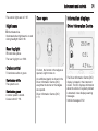
Fuel gauge
Battery gauge
Driving efficiency gauge
Displays the fuel level in the tank and
the fuel range.
Never run the tank dry.
Because of the fuel remaining in the
tank, the top-up quantity may be less
than the specified tank capacity.
Extended range mode 3 107.
Displays the charge level and the
range of the high voltage battery.
Electric mode 3 107.
This gauge is a guide to driving in an
efficient manner by keeping the ball
green and in the centre of the gauge.
The leaves stop spinning when the
vehicle stops or when the ball travels
away from the centre of the gauge.
accel: If the ball turns yellow and
travels above the centre of the gauge,
acceleration is too aggressive to
optimise efficiency.
brake: If the ball turns yellow and
travels below the centre of the gauge,
braking is too aggressive to optimise
efficiency.
64
Instruments and controls
Driving economically 3 102
Depending on the setting, this gauge
can be hidden and be replaced by
either the fuel or the battery gauge.
Driver Information Centre (DIC)
3 71.
Total vehicle range
Displays the total vehicle range
combining the electric range and fuel
range.
Driving economically 3 102.
Service display
The engine oil life system displays the
percentage of the remaining oil life.
Based on driving conditions, the
interval at which an engine oil and
filter change will be indicated can vary
considerably.
The system must be reset every time
the engine oil is changed to allow
proper functionality. Seek the
assistance of a workshop.
When the system has calculated that
engine oil life has been diminished,
Change Engine Oil Soon appears in
the Driver Information Centre. Have
engine oil and filter changed by a
workshop within the next 600 miles.
Driver Information Centre 3 71.
Service information 3 173.
Control indicators
The control indicators described are
not present in all vehicles. The
description applies to all instrument
versions. Depending on the
equipment, the position of the control
indicators may vary. When the
ignition is switched on, most control
indicators will illuminate briefly as a
functionality test.
The control indicator colours mean:
red
= danger, important
reminder
yellow = warning, information, fault
green = confirmation of activation
blue
= confirmation of activation
white = confirmation of activation
Instruments and controls
Control indicators in the instrument cluster
65
66
Instruments and controls
Control indicators in the
overhead console
Turn signals 3 89.
Seat belt reminder
Seat belt reminder on front
seats
X for driver's seat illuminates or
flashes red.
k for front passenger seat illuminates
or flashes red, when seat is occupied.
The seat belt reminder of the front
passenger seat may also turn on if an
object is put on the seat.
Turn signal
O Illuminates or flashes green.
Flashes
The control indicator flashes if a turn
signal or the hazard warning flashers
are activated.
Fast flashing: failure of a turn signal
light or associated fuse.
Bulb replacement 3 144.
Fuses 3 147.
Illuminates
After the warning lights of the
respective front seat have flashed for
a while, until the seat belt has been
fastened.
Flashes
Up to a certain time after the ignition
has been switched on.
Seat belt status on rear seats
6 flashes or illuminates.
Illuminates
After the ignition has been switched
on, the seat belt light illuminates red.
After the passenger seat belts have
been buckled, the corresponding seat
belt light turns green.
Flashes
While the vehicle is moving, if a
second row passenger who was
previously buckled becomes
unbuckled, the corresponding seat
belt symbol will flash red for several
seconds and a chime may sound.
Fastening the seat belt 3 39.
Airbag and belt tensioners
v illuminates red.
When the ignition is switched on, the
control indicator illuminates for
several seconds. If it does not
illuminate, does not go out after some
seconds or illuminates whilst driving,
there is a fault in the airbag system.
Seek the assistance of a workshop.
Instruments and controls
The airbags and belt pretensioners
may fail to trigger in the event of an
accident.
A message may also display in the
Driver Information Centre (DIC).
Deployment of the belt pretensioners
or airbags is indicated by continuous
illumination of v.
9 Warning
Have the cause of the fault
remedied immediately by a
workshop.
The front passenger frontal and knee
airbag are deactivated 3 43.
9 Danger
Risk of fatal injury for a child using
a child restraint system on a seat
with activated front passenger
frontal and knee airbag.
Risk of fatal injury for an adult
person on a seat with deactivated
front passenger frontal and knee
airbag.
67
Light stays on or illuminates
while driving
1. Move out of the flow of traffic as
quickly as possible without
impeding other vehicles.
2. Stop, switch off the ignition.
3. Seek the assistance of a
workshop.
Driving while this light is on could
drain the 12 volt battery.
Malfunction indicator light
Belt pretensioners, airbag system
3 38, 3 41.
Driver Information Centre (DIC)
3 71.
If, after several seconds, both status
indicator lights remain on or if there
are no lights at all, there may be a
problem with the lights or the airbag
deactivation switch. Seek the
assistance of a workshop.
Airbag deactivation
Charging system
Illuminates as a check, showing if the
service only mode is working. If a fault
is detected, seek the assistance of
your workshop.
Power button 3 103.
p illuminates red.
Illuminates briefly when the ignition is
switched on.
Illuminates when the ignition is
on
V illuminates yellow.
The front passenger frontal and knee
airbag are activated.
W illuminates yellow.
Z illuminates or flashes yellow.
Illuminates in service only mode
Fault in the emission control system.
The permitted emission limits may be
exceeded.
68
Instruments and controls
The following may correct an
emission system malfunction:
■ Ensure that the fuel cap is installed
correctly.
■ Ensure that good quality fuel is
used.
If none of the above have made the
light turn off, seek the assistance of a
workshop immediately.
Flashes when the ignition is on
Misfire condition has been detected.
Ease up on the accelerator, reduce
vehicle speed and/or avoid steep
uphill grades until the flashing stops.
Should the light continues to flash:
1. Move out of the flow of traffic as
quickly as possible without
impeding other vehicles.
2. Stop, switch off the ignition.
3. Wait at least 10 seconds and
switch the ignition on again.
If the light is still flashing, seek the
assistance of a workshop.
Brake system
R illuminates red.
Illuminates after the ignition is
switched on. The brake fluid level is
too low or any other problem with the
brake system exists.
Brake fluid level 3 142.
9 Warning
Stop. Do not continue your
journey. Consult a workshop.
Electrical parking brake
P illuminates or flashes red.
Illuminates
Electrical parking brake is applied
3 113.
Flashes
If P flashes after the parking brake is
released or while driving, do not drive
and seek the assistance of a
workshop immediately.
Electrical parking brake
fault
p illuminates yellow.
Illuminates
Electrical parking brake is operating
with degraded performance 3 113.
9 Warning
Have the cause of the fault
remedied immediately by a
workshop.
An error message may be displayed
in the Driver Information Centre
(DIC).
Driver Information Centre 3 71.
Antilock brake system
(ABS)
u illuminates yellow.
Illuminates for a few seconds after the
ignition is switched on. The system is
ready for operation when the control
indicator goes out.
Instruments and controls
If the control indicator does not go out
after a few seconds, or if it illuminates
while driving, there is a fault in the
ABS. The brake system remains
operational but without ABS
regulation.
Try to reset the system.
To reset the system:
1. Move out of the flow of traffic as
quickly as possible without
impeding other vehicles.
2. Place the vehicle in P.
3. Switch the ignition off.
4. Restart the vehicle.
When the ABS control indicator
remains on after resetting the system
or comes on again while driving, seek
the assistance of a workshop.
Antilock brake system 3 113.
Should the warning lights of the ABS
and the regular brake system come
on, the vehicle may have a problem
with the regular and the antilock
brakes.
Have the vehicle towed for service.
Towing 3 169.
Sport mode
Sport illuminates when sport mode is
selected.
Sport mode 3 108.
Mountain mode
Mountain illuminates when mountain
mode is selected.
Mountain mode 3 108.
Hold mode
Hold illuminates when hold mode is
selected.
Hold mode 3 108.
Electronic Stability Control
off
a illuminates yellow.
The system is deactivated.
69
Electronic Stability Control
and Traction Control
system
b illuminates or flashes yellow.
Illuminates
A fault in the system is present.
Continued driving is possible. Driving
stability, however, may deteriorate
depending on road surface
conditions.
Have the cause of the fault remedied
by a workshop.
Flashes
The system is active and is working to
assist the driver with directional
control of the vehicle in difficult driving
conditions.
Electronic stability control 3 117,
Traction control system 3 116.
Traction Control system off
k illuminates yellow.
The system is deactivated.
70
Instruments and controls
Engine coolant
temperature
W illuminates red.
Illuminates when the vehicle has a
problem with the engine coolant
system.
A warning chime sounds when the
control indicator comes on.
Caution
If engine coolant temperature is
too high, stop vehicle, switch off
the ignition. Danger to engine.
Check coolant level.
If the control indicator remains on,
seek the assistance of your
workshop.
Tyre pressure monitoring
system
A illuminates or flashes yellow.
Illuminates
One or more of the tyres are
significantly underinflated. Stop
immediately and check tyre pressure.
Flashes
Fault in system. After about
one minute the control indicator
illuminates continuously. Seek the
assistance of a workshop.
1. Move out of the flow of traffic as
quickly as possible without
impeding other vehicles.
2. Set selector lever to N.
3. Switch off the ignition.
Check oil level before seeking
assistance of a workshop 3 138.
Low fuel
Engine oil pressure
Y illuminates when the fuel level is too
low.
I illuminates red.
Illuminates briefly when the vehicle is
started.
Immobiliser
Caution
Engine lubrication may be
interrupted. This may result in
damage to the engine and/or
locking of the drive wheels.
d illuminates yellow.
Fault in the immobiliser system. The
engine cannot be started.
Seek the assistance of a workshop.
Vehicle ready
R illuminates whenever the
vehicle is ready to be driven.
Exterior light
8 illuminates green.
Instruments and controls
The exterior lights are on 3 87.
Door open
71
Information displays
Driver Information Centre
High beam
C illuminates blue.
Illuminated when high beam is on and
during headlight flash 3 88.
Rear fog light
r illuminates yellow.
The rear fog light is on 3 89.
Cruise control
m illuminates white or green.
Illuminates white
The system is on.
Illuminates green
A certain speed is stored.
Cruise control 3 118.
If a door, the bonnet or the tailgate is
opened, a light comes on.
An additional graphic is shown in the
Driver Information Centre (DIC),
everytime the bonnet or the tailgate
are opened.
Driver Information Centre (DIC)
3 71.
The Driver Information Centre (DIC)
display is located in the instrument
cluster. The DIC displays information
about the vehicle. If a system problem
is detected, it also displays warning
messages.
Vehicle messages 3 82.
72
Instruments and controls
DIC controls
CONFIG: Press to select either the
simple or enhanced instrument
cluster configuration display.
9 BACK: Press to return to the
previous screen, to exit a screen or
return to the main menu. Press 9
BACK to minimise the DIC menu
display.
SELECT: Press the centre of the
knob to select the highlighted item.
Turn the knob to scroll through the
menu items.
Selecting menus and functions
At the main DIC menu:
1. Turn the SELECT knob to scroll
through the possible DIC menus.
2. Press SELECT knob when a
menu item is highlighted to enter
that menu.
3. Continue to turn and press the
SELECT knob to scroll through
and select the available menu
items:
Trip A 0 and Trip B 1
3 62.
Remaining oil life I
The percentage of remaining oil life is
displayed.
Engine oil 3 138.
Tyre pressure 2
The approximate pressures of all four
tyres are displayed.
If dashes are displayed instead of
values, there may be a problem with
the vehicle.
Seek the assistance of a workshop.
Tyre pressure 3 156.
Tyre pressure monitoring system
3 156.
Vehicle messages 3
Turn the SELECT knob to scroll
through any active warning message.
Press SELECT to review the
messages.
Vehicle messages 3 82.
Unit 7
Turn the SELECT knob to change the
unit display between SI and US.
Press SELECT to confirm the setting.
Tutorial mode T
Press CONFIG to switch between two
tutorial screens that explain some of
the features of the cluster.
Tutorial mode is only available when
the vehicle is in park position P.
Navigation *
Arrow guidances are displayed by
selecting this item.
See the infotainment system manual
for further information.
Instruments and controls
Instrument cluster display
After unlocking and opening the
driver's door, an information display
appears, indicating the charge cord
status and the charge level of the high
voltage battery.
A message may display on the lower
left of the screen to indicate that a
charging interruption of AC power at
the vehicle's charge port has
occurred.
Colour-Info-Display
Colour-Info-Display is located in the
instrument panel.
Colour-Info-Display indicates:
■ Climate control 3 93
■ Infotainment system, see
description in the infotainment
system manual.
■ Vehicle personalisation settings
■ Power flow information
■ Charging settings
■ Energy information
■ Time 3 60
■ Temperature
The Colour-Info-Display controls only
need a light touch to operate and work
best with bare hands. The controls
will work with most gloves although
they may take longer to respond. Use
the finger pad rather than the finger
tip to minimise response time. If the
controls are not responding, remove
the gloves.
Press 8 until Power Flow ,
Charging and Energy Info is
displayed.
Power Flow screens
73
74
Instruments and controls
The Power Flow screens indicate the
current system operating condition.
The screens show the energy flow
between the engine, electric drive unit
and high voltage battery. These
components will be highlighted when
they are active.
Charging
Charge mode selection
There are three programmable
charge modes.
From the charge mode status screen,
press Change Charge Mode.
Select one option:
■ Immediately upon plug-in
■ Delayed based on departure time
■ Delayed based on electric rates &
departure time
Programmable charging
The current charge mode status can
also be viewed in a temporary pop-up
in the Colour-Info-Display by pressing
the release button of the charge port
door on the driver door. The Charge
Start and Charge Complete time
estimations are also displayed on the
screen. These estimations are most
accurate when the vehicle is plugged
in and in moderate temperature
conditions.
Charge mode status
Immediately:
The vehicle starts charging as soon
as it is connected to an electrical
outlet.
Charging 3 124.
Delayed (Departure Time):
Instruments and controls
75
Departure time entry
From the delayed charge mode
status screen, press Edit to change
the departure time for each day of the
week.
The vehicle estimates the charging
start time considering the
programmed departure time for the
current day of the week. Charging
begins at the start time and is
complete by the departure time only if
sufficient time is allowed after the
charge cord is plugged in.
Delayed (Rate & Departure Time):
The vehicle estimates the charging
start time based on the utility rate
schedule, utility rate preference and
the programmed departure time for
the current day of the week. The
vehicle will charge during the least
expensive rate periods to achieve a
full battery charge by the departure
time. Electrical rate information from
the utility company for the charging
location is required for this mode.
1. Press the day to change.
2. Press + or − to change the hours
and minutes.
3. Press Back to store changes and
return to the previous screen.
Charge rate selection
From the delayed rate and departure
time charge mode status screen,
press Edit.
76
Instruments and controls
Select one of the following:
■ Edit Electric Rate Schedule
■ Edit Departure Time Schedule
■ Select Charge Rate Preference
Charge rate preference selection
From the Departure Time & Rate
Information screen, press Select
Charge Rate Preference.
Press one of the following options to
select the Charge Rate Preference:
■ Charge during Peak, Mid-Peak, &
Off-Peak Rates: The vehicle can
charge during any rate period to
satisfy the next planned departure
time. However, it will select when to
charge to minimise the total cost of
the charge.
■ Charge during Mid-Peak & OffPeak Rates: The vehicle will charge
during off-peak and/or mid-peak
rate periods only and will select
when to charge to minimise the
total cost of the charge.
■ Charge during Off-Peak Rates: The
vehicle will only charge during offpeak rate periods.
Electric rate plan selection
Electric rates can vary depending on
time, weekday and season.
Contact the utility company to obtain
the rate schedule for your area. The
summer and winter start dates must
be established to use a summer /
winter schedule.
From the Departure Time & Rate
Information screen, press Edit
Electric Rate Schedule.
Two electric rate plans are
selectable:Summer/Winter Schedule
or Yearly Schedule . To edit:
1. Press Summer/Winter
Scheduleor Yearly Schedule .
2. Press Edit.
Summer/Winter schedule start date
entering
From the Select Electric Rate Plan
screen, press Summer/Winter
Schedule then press Edit.
Instruments and controls
77
The finish times must be consecutive.
If a finish time does not follow a start
time, an error message displays.
Follow the instructions given by the
message.
1. Press Summer Start.
2. Press + or − to set the month and
day for the start of summer.
3. Press Winter Start.
4. Press + or − to set the month and
day for the start of winter.
5. Press Edit Summer Schedule or
Edit Winter Schedule to edit the
daily electric rate schedule.
Electric rate schedule editing
From the Enter Summer/Winter Start
Dates screen, press Edit Summer
Schedule or Edit Winter Schedule.
From the Select Electric Rate Plan
screen, press Yearly Schedule and
then press Edit.
1. Press Weekday or Weekend.
2. Press Edit next to the row to be
changed.
◆ Weekdays are Monday to
Friday and use the same rate
schedule.
◆ Weekends are Saturday and
Sunday and use the same rate
schedule.
Both weekday and weekend
schedules must be set. The rate
schedule only applies for a 24 hour
period, starting at 0:00 and ending at
0:00. There can be five rate changes
for each day; not all must be used.
Electric rate finish time editing
From the respective electric rate
schedule screen, press Edit next to
the row to change.
1. Press + or − to adjust the time.
2. Press Peak, Mid-Peak or OffPeak to select the electric rate.
3. Press Back to store changes.
Only the finish time can be edited.
The start time is automatically
populated in the rate table.
78
Instruments and controls
Electric rate schedule viewing
From the Select Electric Rate Plan
screen, press either View Summer
Schedule, View Winter Schedule or
View Yearly Schedule.
Temporary charge mode override
and cancel
Programmed delayed charge modes
can be temporarily overridden to an
Immediate charge mode for one
charge cycle. Also, the next planned
departure time can be temporarily
overridden for one charge cycle. In
addition to the in-vehicle overrides via
the Colour-Info-Display, there are
also other ways to temporarily
override a delayed charge mode.
Charging 3 124.
To temporarily override a delayed
charge mode to immediate charge
mode from inside the vehicle:
1. Press the release button of the
charge port door on the driver
door to view the charge mode
status pop-up in the Colour-InfoDisplay.
2. Press Temporary Override.
3. Press Charge Immediately on
Plug-in to temporarily override an
immediate charge mode.
The revised charge complete time will
be automatically displayed.
Instruments and controls
79
2. Press Temporary Override.
To cancel the temporary override to
immediate, press Cancel Temporary
Charge Mode.
To temporarily override the next
planned departure time from inside
the vehicle:
1. Press the release button of the
charge port door on the driver
door to view the charge mode
status pop-up in the Colour-InfoDisplay.
3. Press the + or – button to change
the next departure time.
4. Press Confirm Departure Time to
temporarily override the next
planned departure time.
The revised charge complete time will
be automatically displayed in the
temporary charge mode screen.
Temporary departure time can only
be updated for the same day as the
original next planned departure time.
Also, the vehicle will not accept a
temporary departure time that is
before the present time of day.
To cancel the temporary override of
the next planned departure time,
press Cancel Temporary Departure
Time on the bottom of the touch
screen of the of the touch screen of
the temporary charge mode screen or
pop-up, respectively.
80
Instruments and controls
Charging override / interruption popup
Programmable charging disabled
If the programmable charging system
is consistently disabled, seek the
assistance of a workshop.
Energy information
To view the Energy Usage, Energy
Efficiency and Efficiency Tips, press
8 on the instrument panel and then
press Energy Info .
Energy Usage
A pop-up will appear if the following
occur:
■ There was an unintended loss of
AC power during the plug-in charge
event. For example, there was a
power outage or the charge cord
was unplugged from the wall.
When the programmable charging
system is disabled, the screen and
the pop-up of the default charge
mode status will display - -:- - for the
charge complete time. The
programmable charging system will
be disabled if the charge complete
time cannot be confidently estimated.
This screen displays information for
the total of all the drive cycles since
the last time the high voltage battery
was fully charged. This includes
distance travelled in electric mode,
distance travelled in extended range
mode, total distance travelled, electric
energy used from the battery, total
fuel used and average fuel economy.
Instruments and controls
There are maximum limits to some of
the values that can be displayed.
When these values are replaced with
dashes, the value limits have been
reached. To reset these values, the
high voltage battery will need to be
fully recharged. The circle graph also
represents the percentage of
distance travelled using electric mode
versus extended range mode. The
lifetime fuel economy is a total over
the life of the vehicle and can only be
reset by a workshop.
Energy usage information will also
appear automatically on power off
when the retained power off is active.
This automatic pop-up can be
disabled through the vehicle
personalisation.
Vehicle personalisation 3 82.
81
Efficiency Tips
Energy efficiency
This screen is accessed by pressing
Energy Efficiency on the Energy Info
screen. This screen displays the
energy efficiency over the drive cycle
based on driving style and climate
settings. Driving in a more efficient
manner will result in a higher
percentage displayed for driving
style. Minimising the use of the
climate control system will result in a
higher percentage displayed for
climate setting.
This screen is accessed by pressing
Efficiency Tips from the Energy Info
screen. This screen provides a guide
on how to improve energy usage to
increase fuel economy and range.
82
Instruments and controls
Vehicle messages
Messages displayed in the Driver
Information Centre (DIC) indicate the
status of the vehicle or some action
that may be needed to correct a
condition. Multiple messages may
display one after the other.
Messages that do not require
immediate action can be
acknowledged and cleared by
pressing the SELECT knob. The
messages requiring immediate action
cannot be cleared until that action is
performed. All messages should be
taken seriously.
Follow the instructions given in the
messages.
The system displays messages
regarding the following topics:
■ Fluid levels
■ Starting
■ Maintenance
■ Anti-theft alarm system
■ Brakes
■ Ride control systems
■
■
■
■
■
■
■
■
■
■
■
■
Cruise control
Object detection systems
Lighting, bulb replacement
Wiper/washer system
Doors, windows
Radio remote control
Airbag systems
Engine and electric drive unit
Tyres
Battery and charging
Vehicle operation modes
Speed limit
Vehicle personalisation
Vehicle Personalisation can be
accessed by using either the
infotainment controls or the touch
screen in the Colour-Info-Display.
See the separate infotainment
manual for more information.
Using the infotainment controls
Use the TUNE/MENU knob, the
CONFIG and the 9BACK buttons on
the instrument panel to select
personalisation features.
Instruments and controls
■ CONFIG: Press to scroll through
the available menus across the top
of the touch screen display.
■ TUNE/MENU:
◆ Press to enter, select or activate
a highlighted menu option.
◆ Turn to highlight a menu option.
◆ Press to turn a system setting on
or off.
■ 9BACK:
◆ Press to exit a menu.
◆ Press to return to a previous
screen.
Turning a function on or off
1. Turn the TUNE/MENU knob to
highlight the function.
2. Press the TUNE/MENU knob to
turn the function on or off. A
checkmark next to the function
indicates that the function is on.
Submenus
An arrow on the right‐hand edge of
the menu indicates that it has a
submenu with other options.
Back: Touch Back in the upper right
corner of the display to return to the
previous menu.
Selecting a menu option
1. Turn the TUNE/MENU knob to
highlight the function.
2. Press the TUNE/MENU knob to
select the highlighted option. A
checkmark next to the option
indicates the selected option.
Using the touch screen
Use the touch screen icons and
menus on the Colour-Info-Display to
select personalisation features.
{ = Touch to scroll up.
} = Touch to scroll down.
Submenus
An arrow on the right‐hand edge of
the menu indicates that it has a
submenu with other options.
83
Selecting a menu option
Touch any of the available menu
options on the touch screen to select
the option. A checkmark next to the
option indicates the selected option.
Turning a function on or off
Touch the screen where the available
function is listed to turn it on or off. A
checkmark next to the function
indicates that the function is on.
Entering the personalisation
menu
Press vehicle menu on the touch
screen.
84
Instruments and controls
The vehicle menu features may
include:
■ Climate and air quality
■ Comfort & Convenience
■ Languages
■ Exterior ambient lighting
■ Power door locks
■ Remote Lock / Unlock / Start
■ Restore factory settings
Climate and air quality
Select the Climate and air quality
menu to display:
■ Auto fan speed
■ Auto heated seats
■ Auto demist
Auto fan speed
Auto fan speed sets the automatic fan
speed to maintain the desired interior
temperature. Choose a blower
setting:
High: Increased speed.
Medium: Moderate speed.
Low: Reduced speed.
Auto heated seats
When enabled, the auto heated seat
button on the touch screen will be
highlighted. This feature will
automatically activate heated seats at
the level required by the interior
temperature. Auto heated seats can
be turned off by using the heated seat
buttons on the instrument panel.
Auto demist
When on and high humidity is
detected, the climate control system
will adjust the outside air, air
conditioning or heat to decrease
fogging. The fan speed may increase.
When high humidity is no longer
detected, the system will return to
previous operation.
Comfort & Convenience
Select the Comfort & Convenience
menu and the following will be
displayed:
■ Chime volume
■ Button Chime
■ Energy Summary Exit Pop-up
■ Personalization by driver
■ Charging Cord Theft Alert
■ Charging Power Loss Alert
Chime volume
This setting allows the selection of the
chime volume level to be either
normal or high.
Button Chime
This setting allows a tone to be heard
when a selection is made using the
infotainment system.
Energy Summary Exit Pop-up
This setting allows the Energy
Summary Exit Pop-up to be turned on
or off.
Personalization by driver
This setting allows the radio to store
favourites by driver.
Charging Cord Theft Alert
This setting allows the Charging Cord
Theft Alert to be turned on or off.
Charging Power Loss Alert
This setting allows the Charging
Power Loss Alert to be turned on or
off.
Instruments and controls
Languages
This setting allows the selection of the
desired language.
number plate lights and reversing
lights will illuminate when ( is
pressed on the radio remote control.
Exterior ambient lighting
Power door locks
Select the lighting menu and the
following will be displayed:
■ Duration upon exit of vehicle
■ Exterior lighting by unlocking
Duration upon exit of vehicle
This setting allows the selection of
how long the exterior low beam stays
on when leaving the vehicle and it is
dark outside.
The available options are:
■ Off
■ 30 seconds
■ 1 minute
■ 2 minutes
Exterior lighting by unlocking
This setting allows the vehicle locator
lights to be turned on or off. When on,
the low beam, sidelights, tail lights,
Select Power door locks and the
following will be displayed:
■ Auto door unlock
■ Auto door lock
■ Prevent doorlock while door open
Auto door unlock
This setting allows selection of which
doors will automatically unlock when
the shift lever is set into P.
The available options are:
■ All doors
■ Driver door
■ Off
Auto door lock
This setting allows selection if doors
will automatically lock when the shift
lever is set into D.
85
Prevent doorlock while door open
When on, this setting will keep the
driver's door from locking until the
door is closed. If this feature is turned
on, the Delayed door lock menu will
not be available.
Remote locking, unlocking,
starting
Select Remote Lock / Unlock / Start
and the following will be displayed:
■ Exterior lighting by unlocking
■ Door Unlock
■ Passive door unlock
■ Passive door lock
■ Remote left in vehicle reminder
Exterior lighting by unlocking
When on, the exterior lights will flash
when unlocking the vehicle with the
radio remote control.
Door Unlock
This setting allows the selection of
which doors will unlock when
pressing ( on the radio remote
control.
86
Instruments and controls
The available options are:
■ All doors
■ Driver door
If All doors is selected, all doors will
be unlocked.
If Driver door is selected, only the
driver's door will be unlocked on the
first press of (. All doors will be
unlocked on the second press of
( within five seconds of the prior
press.
Passive door unlock
This setting allows the selection of
which doors are unlocked by pressing
the button on the outside door handle.
The available options are:
■ All doors
■ Driver door
Passive door lock
This setting allows passive locking to
be turned on or off and select what
type of feedback.
The available options are:
■ Off
■ On
■ ON with Active Chirp
Remote left in vehicle reminder
When on, the horn will chirp rapidly
three times if a radio remote control is
left in the vehicle.
Restore factory settings
This setting returns all of the vehicle
personalisation settings to the factory
settings.
Lighting
Lighting
Exterior lighting
Light switch
Exterior lighting ............................ 87
Interior lighting ............................. 90
Lighting features .......................... 91
87
Tail lights
Tail lights are illuminated together
with the low beam and the sidelights.
Automatic light control
Automatic light control function
When the automatic light control
function is switched on and the
ignition is switched on, the system
switches between daytime running
light and low beam depending on the
lighting conditions.
Turn adjuster wheel:
AUTO = automatic light control:
exterior lighting is switched
on and off automatically
depending on external
lighting conditions.
m
= activation or deactivation
of the automatic light
control. Switch turns back
to AUTO.
= sidelights
8
= low beam
9
Daytime running light
Daytime running light increases
visibility of the vehicle during daylight.
While the daytime running light is
active, the tail lights and the sidelights
are switched off.
If the ignition is switched on and the
vehicle is stopped, the datytime
running light can be turned off by
moving the shift lever to P. The
daytime running light will stay off until
the shift lever is moved out of P.
Please regard that the low beam
should be turned on when needed.
88
Lighting
Notice
Do not cover the light sensor
otherwise the AUTO mode will not
operate properly.
Automatic low beam activation
During poor lighting conditions, the
low beam is switched on.
Tunnel detection
When a tunnel is entered, the low
beam is switched on.
To switch to low beam, push lever
again or pull.
Headlight flash
To activate the headlight flash, pull
the turn signal lever.
2 = all seats occupied and load
compartment laden
3 = driver's seat occupied and load
compartment laden
Hazard warning flashers
Headlight range
adjustment
High beam
To switch from low to high beam,
push the turn signal lever.
To adapt headlight range to the
vehicle load to prevent dazzling: turn
thumb wheel ? to required position.
0 = front seats occupied
1 = all seats occupied
Operated with the ¨ button.
In the event of an accident with airbag
deployment, the hazard warning
flashers are activated automatically.
Lighting
Turn and lane-change
signals
Switch the turn signal off manually by
moving the lever to its original
position.
Turn signal control indicator 3 66.
Rear fog lights
lever up
= right turn signal
lever down = left turn signal
If the lever is moved past the
resistance point, the turn signal is
switched on constantly. When the
steering wheel moves back, the turn
signal is automatically deactivated.
For three flashes, e.g. when changing
lanes, press the lever until resistance
is felt and then release.
89
Parking lights
When the ignition is switched off, the
parking lights on one side can be
activated:
1. Switch off the vehicle.
2. Move turn signal lever all the way
up (right parking lights) or down
(left parking lights).
Confirmed by a signal and the
corresponding turn signal control
indicator.
The parking lights will remain
illuminated until the ignition is
switched on or the turn signal lever is
returned to the neutral position.
Reversing lights
Turn the rear fog light band on the
lever to r and release it, to turn the
rear fog light on or off. The band will
return to its original position.
The rear fog light is automatically set
to off each time the car is started.
Head- and sidelights must be on for
the rear fog lamp to work.
The reversing lights come on when
the ignition is switched on and
reverse gear is selected.
Electric drive unit 3 111.
90
Lighting
Misted light covers
The inside of the light housing may
mist up briefly in poor, wet and cold
weather conditions, in heavy rain or
after washing. The mist disappears
quickly by itself; to help switch on the
low beam.
Interior lighting
Dome lights
Instrument panel
illumination control
Brightness of the following lights can
be adjusted when the exterior lights
are on:
■ Instrument panel cluster display
■ Infotainment display
■ Illuminated switches and operation
elements
Turn thumb wheel A up or down to
brighten or dim the lights.
To operate, press the following
buttons:
w = automatic switching on and off
u = on
v = off
Reading lights
There are front and rear reading
lights.
The reading lights are operated with
s and t for the respective light.
Lighting
Front reading lights
Rear reading lights
91
Lighting features
Entry lighting
Low beam, reversing lights and the
interior lights turn on briefly by
pressing ( on the radio remote
control.
The lights turn off immediately when
the m button is pressed or
automatically after a brief period.
Exit lighting
The front reading lights are located in
the overhead console.
The rear reading lights are located in
the headliner.
The low beam and the reversing lights
come on by doing the following:
1. Switch off ignition.
2. Open the driver´s door.
3. Pull the turn signal lever briefly
and release.
Some interior lights come on when
the ignition is switched off. The
exterior and the interior lights remain
on after the door is closed for a brief
period and then turn off.
Activation, deactivation and duration
of this function can be changed in the
Colour-Info-Display.
92
Lighting
Vehicle personalisation 3 82.
Battery discharge
protection
The battery saver feature is designed
to protect the vehicle's 12 volt battery.
If any interior light is left on and the
ignition is switched off, the battery
rundown protection system
automatically turns the lights off after
about 10 minutes.
If the exterior lights are left on, they
turn off when the ignition is switched
off. If the sidelights are switched on
when the ignition is switched off, the
sidelights remain on until they are
manually turned off.
Climate control
Climate control
Climate control systems ............... 93
Air vents ..................................... 100
Maintenance .............................. 101
Climate control systems
Automatic climate control
system
93
CLIMATE button on the instrument
panel and viewing information in the
Colour-Info-Display.
Climate mode operation
Notice
Do not cover the sensor located on
top of the instrument panel,
otherwise the automatic climate
control system may not work
properly.
Climate control touch screen
Three different climate mode settings
can be selected. These settings
adjust the impact the climate control
system has on the vehicle's electric
range or fuel economy.
The climate mode, fan, air delivery,
recirculation and auto heated seats
are controlled by pressing the
94
Climate control
To select a climate mode:
1. Press CLIMATE on the
instrument panel.
2. Press the respective climate
mode button the touch screen.
The climate mode will be lit.
Climate modes
MIN a mode
The air conditioning and electric heat
are turned off. As long as V is not
selected, the climate control settings
may not have a noticeable effect on
the vehicle electric range and fuel
economy.
When in MIN a mode, the AUTO
indicator light will be off. When
AUTO is selected in Min a mode,
the mode will change to either ECO
a or MAX a.
When in MIN a mode, the air
conditioning system may turn on
automatically if the high voltage
battery is being cooled. The climate
control system could blow cold air.
This is normal. To prevent cold air
from blowing into the interior, turn off
the fan control and select the vent
mode and manual recirculation mode,
and close the air vents.
When in MIN a mode, if automatic
defog is enabled, the air conditioning
and electric heat may turn on when
high humidity conditions exist.
Vehicle personalisation 3 82.
The air conditioning may also run if
V is selected.
economy will decrease depending on
the amount of energy required to
reach the best comfort levels.
ECO a mode
The air conditioning and electric heat
are controlled to balance comfort with
fuel economy.
As long as V is not selected, the
vehicle electric range or fuel economy
will decrease less than in MAX a
mode, but will result in moderate
comfort.
When the climate mode is changed,
the climate power gauge displays the
impact that the changes have on
energy use. The higher the reading,
the more energy is being used.
MAX a mode
The air conditioning and electric heat
are controlled to reach the best
comfort level based on the
temperature setting selected. In this
mode, vehicle electric range or fuel
Climate power gauge
Air conditioning / Heat status
indicators
Climate control
The air conditioning or heat status
indicator displays when the air
conditioning or electric heat is being
used.
Air conditioning / Electric
heating
Air conditioning and electric heating
could be on at the same time when
dehumidifying is required in ECO
a or MAX a modes.
In MIN a mode, occasionally air
conditioning and/or heating status will
be on if the auto defog function is
enabled and high humidity is
detected.
Vehicle personalisation 3 82.
Air conditioning may also run if V is
selected, regardless of the climate
mode.
Automatic operation
The system automatically controls the
fan speed, air delivery mode and
recirculation to heat or cool the
vehicle to the selected temperature.
It is also possible to preset three fan
speeds in the vehicle personalisation.
95
Vehicle personalisation 3 82.
When the AUTO indicator light is on,
the system is in full automatic
operation. If the air delivery mode, fan
speed or recirculation setting is
adjusted, the AUTO indicator turns off
and the selected settings display.
For automatic operation:
2. Set the temperature to the desired
value. An initial setting of 23° C is
recommended.
1. Press AUTO.
96
Climate control
Temperature control
Manual operation
Fan control
Press R or S to increase or decrease
the temperature.
Auto defog
The system monitors high humidity
inside the vehicle. When detected,
the system may adjust to outside air
supply and turn on the air conditioning
or the heater. The fan speed may
slightly increase to help prevent
fogging. When high humidity is no
longer detected, the system will
return to its prior operation.
Vehicle personalisation 3 82.
Press the fan control buttons x on the
instrument panel or the touch screen
fan control, to increase or decrease
the fan speed.
The fan speed setting is displayed.
Press AUTO to return to automatic
operation. To turn the fan or climate
control system off, press the fan down
button repeatedly.
If the fan is manually turned off while
in ECO a or MAX a mode, the
display will automatically change to
MIN a mode. When the fan is
turned back on either by manually
increasing fan speed or pressing the
AUTO button, the climate mode will
revert back to ECO a or MAX a
mode.
Climate control
Air delivery mode control
Press CLIMATE on the instrument
panel to select the climate touch
screen.
Press the air delivery mode button on
the touch screen to change the
direction of the airflow. The selected
air delivery mode button is lit.
Pressing any of the air delivery
buttons cancels automatic air delivery
control and the direction of the airflow
can be controlled manually. Press
AUTO to return to automatic
operation.
To change the current mode, select
one of the following:
M: to head via adjustable air vents
L: to head and to foot well
K: to floor well
9: to windscreen and front door
windows
V: Air is directed to the windscreen.
The windscreen is cleared of fog or
frost more quickly.
97
If V is selected in MIN a or ECO
a mode, air conditioning or electric
heating may turn on and have a
noticeable effect on vehicle electric
range and fuel economy.
Auto recirculation
9 Warning
The exchange of fresh air is
reduced in air recirculation mode.
In operation without cooling the air
humidity increases, so the
windows may mist up from inside.
The quality of the passenger
compartment air deteriorates,
which may cause the vehicle
occupants to feel drowsy.
Selecting V will disable automatic
control and the AUTO button indicator
will not be lit.
Select V again to return to the
previous climate settings.
98
Climate control
Manual recirculation
Manual recirculation mode is not
available when defrosting or
defogging is selected.
Auto heated seats
Press AUTO 4 to allow the system
to automatically choose the air supply
mode for best comfort, efficiency and
defogging. Air is recirculated or
outside air is pulled into the vehicle.
The touch screen button is lit.
Press 4 to recirculate air inside the
vehicle, press it again to select
outside air. When selected, the touch
screen button lights up to indicate that
air is being recirculated. This helps to
quickly cool the air inside the vehicle
or prevent outside air and odours
from entering.
Pressing 4 cancels automatic
recirculation. Press AUTO or AUTO
4 to return to automatic operation;
recirculation runs automatically as
needed.
Press ß AUTO on the touch screen.
The button colour will change to
green to confirm the setting. By
switching on the ignition, AUTO
heated seats will automatically
activate the heated seats at the level
required by the vehicle's interior
temperature. The LEDs next to the
seat heating symbol on the
instrument panel indicates the heat
setting. Use the touch screen buttons
Climate control
or the manual heated seat buttons on
the instrument panel to turn auto
heated seats off.
Heated seats 3 36.
Heated rear window
99
Passenger compartment
preconditioning
Manual heated seats
Operated by pressing the Ü button.
Heated rear window 3 32.
Heated rearview mirror 3 29.
Press ß for the respective seat with
the ignition on to operate the seat
heating.
The controls are located on the
instrument panel.
Heated seats 3 36.
Operated by pressing # on the radio
remote control.
The climate control system will default
to an appropriate heating or cooling
mode and the rear window heating
turns on in the event of cold outside
temperatures.
Passenger compartment
preconditioning 3 20.
100
Climate control
Compressor
The vehicle has an electric powered
air conditioning compressor. This
allows for continuous air conditioning
and/or high voltage battery cooling
operation, without running the engine.
Air vents
To open the vent, turn the adjuster
wheel to 7. Adjust the air amount at
the vent outlet by turning the adjuster
wheel.
Direct the flow of air by tilting and
swivelling the slats.
To close the vent, turn the adjuster
wheel to 8.
9 Warning
Do not attach any objects to the
slats of the air vents. Risk of
damage and injury in case of an
accident.
Climate control
Maintenance
Air intake
The air intake in front of the
windscreen in the engine
compartment must be kept clear to
allow air intake. Remove any leaves,
dirt or snow.
Pollen filter
The pollen filter cleans dust, soot,
pollen and spores from the air
entering the vehicle through the air
intake.
Service
For optimal cooling performance, it is
recommended to annually check the
climate control system, starting
three years after initial vehicle
registration, including:
■ Functionality and pressure test
■ Heating functionality
■ Leakage check
■ Cleaning of condenser and
evaporator drainage
■ Performance check
101
102
Driving and operating
Driving and operating
Driving hints
Driving economically
Driving hints ............................... 102
Starting and operating ............... 103
Electric vehicle operation
modes ........................................ 107
Engine exhaust .......................... 111
Electric drive unit ....................... 111
Brakes ........................................ 113
Ride control systems ................. 116
Driver assistance systems ......... 118
Charging .................................... 124
Fuel ............................................ 132
Towing ....................................... 135
Use the following tips to help
maximise energy efficiency and
range.
Driving style
Avoid unnecessary rapid
accelerations and decelerations.
Electric range is maximised at
50 mph and below. Higher speeds
use more energy and can significantly
reduce electric range.
Use cruise control when appropriate.
Do not shift to N to coast. The vehicle
recovers energy while coasting and
braking in D or L.
Efficiency gauge in the instrument
cluster
The ball indicator should be kept
green and in the centre of the gauge.
Inefficient acceleration is indicated
when the ball turns yellow and travels
above the centre of the gauge.
Aggressive braking is indicated when
the ball turns yellow and travels below
the centre of the gauge.
Drive mode and gear mode selection
Use normal mode when possible.
Sport mode provides more
responsive acceleration than normal
mode but can reduce efficiency.
Use mountain mode prior to climbing
long, steep grades in mountainous
areas. Be sure to engage mountain
mode before starting to climb.
Mountain mode reduces electric
range and power but may be needed
to maintain speeds above 60 mph
when climbing grades of 5 % or
greater.
Use L in heavy stop‐and‐go traffic or
when travelling downhill. L requires
less brake pedal application and
provides a controlled, efficient way to
slow the vehicle down.
Driving and operating
Vehicle charging / maintenance
Charging
Keep the vehicle plugged in, even
when fully charged, to keep the
battery temperature ready for the next
drive. This is important when outside
temperatures are extremely hot or
cold.
Maintenance
Always keep the tyres properly
inflated and the vehicle properly
aligned.
The weight of excess cargo in the
vehicle affects efficiency and range.
Avoid carrying more than is needed.
If fuel is not regularly used, consider
keeping the fuel tank only one‐third
full. Excess fuel weight impacts
efficiency and range.
Avoid unnecessary use of electrical
accessories. Power used for
functions other than propelling the
vehicle will reduce electric vehicle
range.
103
Using a rooftop carrier will reduce
efficiency due to additional weight
and drag.
Starting and operating
Control of the vehicle
The vehicle does not require a
running-in period.
Pedals
To ensure the pedal travel is
uninhibited, there must be no mats in
the area of the pedals.
New vehicle running-in
Power button
The vehicle has an electronic pushbutton start. The m button light
flashes when the driver's door is open
and the ignition is not on. The flashing
light will eventually time out. The m
button light is on steady when the
104
Driving and operating
ignition is on. When the ignition is
switched off, the m button light will
also turn off.1)
The radio remote control must be in
the vehicle for the system to operate.
If the vehicle will not start, place the
mechanical key of the radio remote
control inside the transmitter slot
located in the instrument panel
storage compartment.
Starting and stopping the vehicle
3 105.
Switch on ignition
With the ignition off and the brake
pedal applied, press m once to switch
on the ignition. When the R
light is on in the instrument cluster,
the vehicle is ready to be driven. This
could take up to 15 seconds at
extremely cold temperatures. The
engine will only start if needed. If the
vehicle did not start, the instrument
cluster will display a screen with
inactive fuel and battery gauges.
Vehicle ready light3 70.
1)
Starting and stopping the vehicle
3 105.
Ignition off
To switch the ignition off, push button
m with the vehicle in P. Retained
power off will remain active until the
driver's door is opened. When
switching off the ignition, if the vehicle
is not in P, the vehicle is not ready to
be driven, but some of the electrical
features of the vehicle can be used. A
message will appear in the Driver
Information Centre (DIC).
Retained power off 3 104.
Electric drive unit 3 111.
The vehicle has an electric steering
column lock. The lock is activated
when the ignition is switched off and
either front door is opened. A sound
may be heard as the lock actuates or
releases. The steering column lock
may not release with the wheels
turned off centre. If this happens, the
vehicle may not start. Move the
steering wheel from left to right while
attempting to start the vehicle. If this
does not work, seek the assistance of
a workshop.
If the vehicle must be shut off in an
emergency:
1. Brake using a firm and steady
pressure. Do not pump the brakes
repeatedly. This may deplete
power assist, requiring increased
brake pedal force.
2. Shift the vehicle to N. This can be
done while the vehicle is moving.
After shifting to N, firmly apply the
brakes and steer the vehicle to a
safe location.
3. Come to a complete stop, shift to
P and switch the ignition off by
pushing button m.
4. Set the parking brake 3 113.
Retained power off
The following electronic systems can
work until the driver's door is opened
or at the latest for 10 minutes after the
ignition is switched off:
Please regard that the operating condition of the vehicle is meant when "ignition on/off" is used.
Driving and operating
■ Power windows
■ Audio system
■ Power outlets
105
However, the vehicle can still be
driven. Therefore proceed as follows:
1. Open the instrument panel
storage and remove the rubber
mat.
Starting and stopping the
vehicle
Starting
Move the shift lever to P or N. The
propulsion system will not start in any
other position.
Notice
Do not try to shift to P if the vehicle
is moving as the electric drive unit
could be damaged. Shift to P only
when the vehicle is stopped.
The radio remote control must be in
the vehicle. Press the brake pedal
and push m. If the radio remote
control is not in the vehicle or
something is interfering with the
transmitter, a message displays in the
Driver Information Centre (DIC).
Radio remote control 3 20.
A welcome, ready, and goodbye
audio message will be heard in the
vehicle and animated on the
instrument cluster when opening the
driver's door upon entry, when the
vehicle is ready to be driven and when
the ignition is switched off. The
instrument cluster displays an active
fuel or battery gauge, along with an
audio start-up cue, when the vehicle
is ready to be driven.
Starting the vehicle with a low radio
remote control battery
If the vehicle will not start due to a low
radio remote control battery, a
message displays in the DIC.
2. Extend the key blade and place
the blade into the slot.
3. With the vehicle in P or N, apply
the brake pedal and press m on
the instrument panel.
Replace the radio remote control
battery as soon as possible.
Battery replacement 3 20.
106
Driving and operating
Starting the vehicle at low
temperatures
It is recommended to switch on the
ignition while the vehicle is plugged in
when exterior temperatures are
below 0° C.
Should the exterior temperatures be
lower than -32° C, the vehicle has to
be plugged in when the ignition is
switched on.
Restarting
If the vehicle must be restarted while
it is still moving, move the shift lever
to N and press m twice without
pressing the brake pedal. The
propulsion system will not restart in
any other position.
Computers determine when the
engine needs to run. The engine may
start, if required, when the propulsion
system is on.
Electric mode 3 107.
A chime will sound if the driver's door
is opened while the ignition is
switched on. Always press m to
switch the ignition off before exiting.
Stopping
Power button 3 103.
Parking
Notice
Do not allow the vehicle to remain in
extreme temperatures for long
periods without being driven or
being plugged in.
■ Do not park the vehicle on an easily
ignitable surface. Things that can
burn could touch hot exhaust parts
under the vehicle and ignite.
■ Always apply the parking brake.
Pull switch m.
■ Switch off the ignition. Turn the
steering wheel until the steering
wheel lock engages.
■ If the vehicle is on a level surface or
uphill slope, apply the parking
brake and then shift the selector
lever to P before switching off the
ignition. On an uphill slope, turn the
front wheels away from the kerb.
If the vehicle is on a downhill slope,
apply the parking brake and then
shift the selector lever to P before
switching off the ignition. Turn the
front wheels towards the kerb.
■ Lock the vehicle and activate the
anti-theft alarm system.
Driving and operating
Electric vehicle
operation modes
Operation
This vehicle is an extended range
electric vehicle. It uses an electric
propulsion system to drive the vehicle
at all times. Electricity is the vehicle's
primary source of energy, while petrol
is the secondary source.
The vehicle has two modes of
operation: Electric and extended
range. In both modes, the vehicle is
propelled by its electric drive unit. It
converts electrical energy into
mechanical energy to drive the
wheels. The vehicle's performance
remains the same in either mode.
Depending on the selected operation
mode, a battery or a fuel gauge is
shown mainly in the instrument
cluster.
Battery gauge 3 63.
Fuel gauge 3 63.
Electric mode
In electric mode the vehicle does not
use fuel or produce emissions. During
this primary mode, the vehicle is
powered by electrical energy stored
in the high voltage battery. The
vehicle can operate in this mode until
the battery has reached a low charge.
There are some conditions when the
battery charge is high enough to
provide electric mode operation, but
the engine still runs. They are:
■ Cold ambient temperatures.
■ Hot or cold high voltage battery
temperatures.
■ The bonnet being open or not
completely closed and latched.
■ Certain high voltage battery fault
conditions.
■ Engine maintenance mode or fuel
maintenance mode being run.
Extended range mode
When the vehicle reaches the end of
its electric range, it switches to
extended range mode. In this
107
secondary mode, electricity is
produced by the fuel‐powered
engine. This secondary source of
electric power extends the vehicle
range. Operation will continue in
extended range mode until the
vehicle can be plugged in to recharge
the high voltage battery and restore
electric mode.
The high voltage battery will continue
to provide some power and work
together with the engine to provide
peak performance when it is required,
such as driving up a steep incline or
for high acceleration manoeuvres.
The battery will not be charged nor
will electric vehicle range be restored
by the engine.
In either electric mode or extended
range mode, if there is a high voltage
battery fault, the engine may run
without turning off to generate the
required electricity. The malfunction
indicator light will turn on.
Malfunction indicator light 3 67.
108
Driving and operating
Drive modes
Sport mode
Sport mode provides more
responsive acceleration than Normal
mode, but can reduce efficiency. Use
Normal mode whenever possible.
Control indicator Sport3 69.
While driving in electric or extended
range mode, additional operating
modes can be selected.
Mountain mode
Press DRIVE MODE as often as the
desired drive mode is highlited in the
Driver Information Centre (DIC).
After three seconds, the new drive
mode will become active.
At next start, the vehicle will default to
Normal mode.
During some conditions, certain drive
modes may be unavailable. The
unavailable mode is greyed out in the
DIC menu and cannot be selected.
If in Sport, Mountain or Hold mode,
the mode may become unavailable
and the vehicle will return to Normal
mode. The indicator light goes off and
a DIC message displays.
Driver Information Centre (DIC) 3 71.
Mountain mode should be selected at
the beginning of a trip before climbing
steep, uphill grades and when
expecting to drive in very hilly or
mountainous terrain. This mode
maintains a reserve electrical charge
of the high voltage battery to provide
better grade climbing performance.
While driving in Mountain mode, the
vehicle will have less responsive
acceleration. Mountain mode will not
change normal vehicle braking
performance for steep downhill
grades.
If steep hill driving is expected, it is
recommended to select Mountain
mode at least 20 minutes before
driving on steep grades. This will
allow the vehicle time to build a
sufficient battery charge reserve.
Driving and operating
If Mountain mode is not selected for
these conditions, propulsion power
may be reduced and the engine
speed may increase.
Control indicator Mountain 3 69.
Hold mode
Hold mode is only available when the
vehicle is in electric mode. This mode
places the remaining battery charge
into a reserve for the driver to use as
desired. Selecting this mode
transitions the vehicle to extended
range mode to maintain the battery
charge reserve.
Hold mode will not change normal
vehicle acceleration or braking
performance.
Control indicator Hold 3 69.
Maintenance modes
Engine maintenance mode
Engine maintenance mode runs the
engine to keep it in good working
condition after approximately
six weeks of no or very limited engine
operation. Engine maintenance mode
will force the engine to run, even if
there is a charge to power the vehicle.
When engine maintenance mode is
needed, a request screen appears on
the Colour-Info-Display at vehicle
start.
If Yes is selected, engine
maintenance mode will begin. The
engine will run for a set amount of
time without turning off. During
engine maintenance mode, a DIC
message displays to show the engine
maintenance mode percentage
complete.
If No is selected, the engine
maintenance mode request screen
will appear when the vehicle is next
109
started. The engine maintenance
mode request can be delayed for only
one day.
If the engine maintenance mode
request was delayed for one day, it
will automatically start the engine at
the next vehicle start. An engine
maintenance mode notification
screen will appear in the Colour-InfoDisplay.
If the vehicle shuts off during engine
maintenance mode, it will restart the
next time the vehicle is driven. A
message displays to indicate that
engine maintenance mode is active.
If engine maintenance mode is
required and the fuel level is low,
engine maintenance mode may
eventually empty the fuel tank if fuel
110
Driving and operating
is not added. This will result in
reduced, or no power. An adequate
fuel level must be maintained in the
vehicle to keep it operational.
larger amount of fresh fuel will
maximise the length of time before
another fuel maintenance mode is
needed. During fuel maintenance
mode the engine may turn on and off.
When fuel maintenance mode is
needed, a request screen appears on
the Colour-Info-Display at vehicle
start.
Driver Information Centre (DIC) 3 71.
Fuel maintenance mode
Fuel maintenance mode tracks
average fuel age. Old fuel can cause
engine problems. If low engine usage
causes average fuel age to exceed
approximately one year, fuel
maintenance mode will run the
engine to use up the old fuel. The
engine will run until enough fresh fuel
is added to bring the average fuel age
into an acceptable range. Allowing
more old fuel to be used up by fuel
maintenance mode and adding a
If Yes is selected, fuel maintenance
mode will begin. Fuel maintenance
mode will automatically continue at
each vehicle start until fresh fuel is
added.
If No is selected, the fuel
maintenance mode request screen
will appear when the vehicle is next
started. The fuel maintenance mode
request can be delayed for only one
day.
If the fuel maintenance mode request
was delayed for one day, it will start at
the next vehicle start and display the
fuel maintenance mode notification
screen on the Colour-Info-Display.
If fuel maintenance mode is required
and the fuel level is low, fuel
maintenance mode may eventually
empty the fuel tank if fuel is not added.
This will result in reduced, or no
power. An adequate fuel level must
be maintained in the vehicle to keep
it operational.
Driving and operating
Engine exhaust
9 Danger
Engine exhaust gases contain
poisonous carbon monoxide,
which is colourless and odourless
and could be fatal if inhaled.
If exhaust gases enter the interior
of the vehicle, open the windows.
Have the cause of the fault
rectified by a workshop.
Avoid driving with an open load
compartment, otherwise exhaust
gases could enter the vehicle.
Electric drive unit
Operation
The vehicle uses an electric drive
unit. The shift lever is located on the
console between the seats.
P (Park): This position locks the front
wheels. It is the best position to use
when starting the propulsion system
because the vehicle cannot move
easily.
111
9 Warning
It is dangerous to get out of the
vehicle if the shift lever is not fully
in P with the parking brake firmly
applied. The vehicle can roll.
Do not leave the vehicle when the
propulsion system is running, the
vehicle can move suddenly. You
or others could be injured. To be
sure the vehicle will not move,
even when you are on fairly level
ground, always apply the parking
brake and move the shift lever to
P.
Make sure the shift lever is fully in P
before starting the propulsion system.
The vehicle has an electric drive unit
shift lock control system. The brake
pedal must be fully applied first and
then the shift lever button pressed
before shifting from P when the
ignition is on. If you cannot shift out of
P, ease the pressure on the shift
lever, then push the shift lever all the
way into P as you maintain brake
112
Driving and operating
pedal application. Then press the
shift lever button and move the shift
lever into another gear.
Notice
If you have continuous problems to
move the shift lever from P as
mentioned, seek the assistance of a
workshop.
Notice
The shift lock is always functional
except in the case of an uncharged
or low charged 12 volt battery.
Try charging or jump starting the
12 volt battery.
Jump start 3 166.
R (Reverse): Use this gear to back up.
Notice
Shifting to R while the vehicle is
moving forward could damage the
electric drive unit. Shift to R only
after the vehicle is stopped.
N (Neutral): In this position, the
propulsion system does not connect
with the wheels.
D (Drive): This position is for normal
driving. It provides the best fuel
economy. If more power is needed for
passing, and the vehicle is:
■ Going less than 35 mph, push the
accelerator pedal about halfway
down.
■ Going about 35 mph or more, push
the accelerator all the way down.
Notice
If the vehicle seems to accelerate
slowly or not respond when you go
faster, and you continue to drive the
vehicle that way, you could damage
the electric drive unit.
Seek the assistance of a workshop.
L (Low): This position reduces vehicle
speed without using the brakes. You
can use L on hills. It can help control
vehicle speed going down steep
mountain roads along with using the
brakes off and on. You can use L on
very steep hills, in deep snow or in
mud.
Notice
Spinning the tyres or holding the
vehicle in one place on a hill using
only the accelerator pedal may
damage the electric drive unit. If you
are stuck, do not spin the tyres.
When stopping on a hill, use the
brakes to hold the vehicle in place.
Driving and operating
Brakes
Antilock brake system
Antilock brake system (ABS)
prevents the wheels from locking.
ABS starts to regulate brake pressure
as soon as a wheel shows a tendency
to lock. The vehicle remains
steerable, even during hard braking.
ABS control is made apparent
through a pulse in the brake pedal
and the noise of the regulation
process.
For optimum braking, keep the brake
pedal fully depressed throughout the
braking process, despite the fact that
the pedal is pulsating. Do not reduce
the pressure on the pedal.
After starting off, the system performs
a self-test which may be audible.
Control indicator u 3 68.
113
Parking brake
Fault
9 Warning
Electrical parking brake
If there is a fault in the ABS, the
wheels may be liable to lock due
to braking that is heavier than
normal. The advantages of ABS
are no longer available. During
hard braking, the vehicle can no
longer be steered and may
swerve.
Have the cause of the fault remedied
by a workshop.
The electrical parking brake can
always be activated, even if the
ignition is off. To prevent draining of
the 12 volt battery, avoid repeated
cycles of the electrical parking brake
system when the ignition is off.
In case of insufficient electrical
power, the electrical parking brake
cannot be applied or released.
Before leaving the vehicle, check the
control indicator m to ensure the
parking brake is applied.
114
Driving and operating
Electrical parking brake apply
The electrical parking brake can be
applied anytime the vehicle is
stopped. The electrical parking brake
is applied by momentarily lifting up on
the m switch. Once fully applied, the
control indicator m will be on.
While the brake is being applied, the
control indicator m will flash until full
apply is reached. If the light does not
come on, or remains flashing, seek
the assistance of a workshop.
Do not drive the vehicle if the control
indicator m is flashing.
If the electrical parking brake is
applied while the vehicle is in motion,
a chime will sound and a message
displays in the the Driver Information
Centre (DIC). The vehicle will
decelerate as long as the switch is
held in the up position.
Releasing the m switch during the
deceleration, will release the parking
brake. If the m switch is held in the up
position until the vehicle comes to a
stop, the electrical parking brake will
remain applied.
If the control indicator m flashes
continuously, the electrical parking
brake is only partially applied or
released or there is a problem with the
electrical parking brake. If so, a
message is displayed in the Driver
Information Centre (DIC). If m
flashes continuously, release the
electrical parking brake and attempt
to apply it again. If m continues to
flash, do not drive the vehicle. Seek
the assistance of a workshop.
If the electrical parking brake fault
indicator p is on, the electrical parking
brake has detected a system problem
and is operating with reduced
functionality. To apply the electrical
parking brake when p is on, lift up on
the m switch and hold it in the up
position until the control indicator m
remains on. If the electrical parking
brake fault indicator p is on, seek the
assistance of a workshop.
If the electrical parking brake fails to
apply, the rear wheels should be
blocked to prevent vehicle
movement.
For maximum electrical parking brake
force when parking on a hill, pull the
electrical parking brake switch twice.
Electrical parking brake release
To release the electrical parking
brake, switch the ignition on, apply
and hold the brake pedal and push
down momentarily on the m switch. If
attempting to release the electrical
parking brake without the brake pedal
applied, a chime will sound and a
message will be displayed in the DIC.
The electrical parking brake is
released when m is off.
If p is on, the electrical parking brake
has detected a system problem, and
is operating with reduced
functionality. To release the electrical
parking brake when p is on, push
down on the m switch and hold it in
the down position until the control
indicator m is off. If the light remains
on, seek the assistance of a
workshop.
Driving and operating
Notice
Driving with the parking brake on
can overheat the brake system and
cause premature wear or damage to
brake system parts. Make sure that
the parking brake is fully released
and the control indicator m is off
before driving.
Automatic release of the electrical
parking brake
The electrical parking brake will
automatically release if the vehicle is
running, placed into gear and an
attempt is made to drive away. Avoid
rapid acceleration when the electrical
parking brake is applied, to preserve
parking brake lining life.
Electrical parking brake m control
indicator 3 68.
Electrical parking brake fault p
control indicator 3 68.
Driver Information Centre (DIC) 3 71.
Regenerative braking
Regenerative braking takes some of
the energy from the moving vehicle
and turns it back into electrical
energy.
This energy is then stored back into
the high voltage battery system,
contributing to increased energy
efficiency.
The hydraulic disc brakes work with
the regenerative braking to ensure
effective braking, such as when a
high braking demand is requested.
The braking system is computer
controlled and blends the
regenerative braking with the
conventional hydraulic disc brakes to
meet any requirements for
deceleration. The controller interprets
the braking request and uses
regenerative braking, conventional
hydraulic braking or a combination of
both as necessary. Because the
controller applies the hydraulic
brakes through its high pressure
accumulator, you may occasionally
hear the motor‐driven pump when it
recharges the system.
115
In the event of a controller problem,
the brake pedal may be harder to
push and the stopping distance may
be longer.
Driver Information Centre (DIC) 3 71.
116
Driving and operating
Ride control systems
Traction Control system
The Traction Control system (TC) is a
component of the Electronic Stability
Control.
TC improves driving stability when
necessary, regardless of the type of
road surface or tyre grip, by
preventing the drive wheels from
spinning.
As soon as the drive wheels starts to
spin, electric drive unit output is
reduced and the wheel spinning the
most is braked individually. This
considerably improves the driving
stability of the vehicle on slippery road
surfaces.
TC is operational as soon as the
control indicator b extinguishes.
When TC is active b flashes.
9 Warning
Do not let this special safety
feature tempt you into taking risks
when driving.
Adapt speed to the road
conditions.
Control indicator b 3 69.
Deactivation
Control indicator k illuminates and a
message in the Driver Information
Centre (DIC) is displayed.
TC is reactivated by pressing the b
button again.
TC is also reactivated the next time
the ignition is switched on.
Fault
If there is a problem detected with TC,
a message is displayed on the DIC.
When this message is displayed and
b illuminates, the vehicle is safe to
drive but the system is not
operational. Driving should be
adjusted accordingly.
Resetting
TC can be switched off when spinning
of drive wheels is required: Press b
button in the overhead console.
If b comes on and stays on, reset the
system as follows:
1. Stop the vehicle.
2. Switch the ignition off and wait for
15 seconds.
3. Switch the ignition on.
If b still comes on and stays on, seek
the assistance of a workshop.
Driving and operating
Caution
9 Warning
Do not repeatedly brake or
accelerate heavily when TC is off.
The vehicle's driveline could be
damaged.
Do not let this special safety
feature tempt you into taking risks
when driving.
Adapt speed to the road
conditions.
Electronic Stability Control
Electronic Stability Control (ESC)
improves driving stability when
necessary, regardless of the type of
road surface or tyre grip. It also
prevents the drive wheels from
spinning.
As soon as the vehicle starts to
swerve (understeer/oversteer),
electric drive unit output is reduced
and the wheels are braked
individually. This considerably
improves the driving stability of the
vehicle on slippery road surfaces.
ESC is operational as soon as the
control indicator b extinguishes.
When ESC is active, b flashes.
Control indicator b 3 69.
Deactivation
117
depressed until k and n illuminate
and a message in the Driver
Information Centre (DIC) is displayed.
ESC is reactivated by pressing the
b button again.
If cruise control is being used when
ESC activates, cruise control will
automatically disengage. Press the
cruise control button to re-engage
when road conditions allow.
Cruise control 3 118.
Driver Information Centre (DIC) 3 71.
Fault
If there is a problem detected with
ESC, a message is displayed on the
DIC. When this message is displayed
and b illuminates, the vehicle is safe
to drive but the system is not
operational. Driving should be
adjusted accordingly.
For very high-performance driving,
ESC can be deactivated: Press and
hold b button in the overhead console
118
Driving and operating
Resetting
If b comes on and stays on, reset the
system as follows:
1. Stop the vehicle.
2. Switch the ignition off and wait for
15 seconds.
3. Switch the ignition on.
If b still comes on and stays on, seek
the assistance of a workshop.
Driver assistance
systems
Cruise control
The cruise control lets the vehicle
maintain a speed of about 20 mph or
more without keeping your foot on the
accelerator. Cruise control does not
work at speeds below 20 mph.
Do not use the cruise control if it is not
advisable to maintain a constant
speed.
With the Traction Control system or
Electronic Stability Control, the
system may begin to limit wheel spin
while you are using cruise control. If
this happens, the cruise control will
automatically disengage.
Traction Control system 3 116.
Electronic Stability Control 3 117.
The cruise control buttons are on the
steering wheel.
m : Press to turn the cruise control
system on and off. An indicator light
will turn on or off in the instrument
cluster.
y : Press to disengage cruise control
without erasing the set speed from
memory.
RES/+: Move the thumbwheel up to
resume to a previously set speed or
to accelerate.
Driving and operating
SET/-: Move the thumbwheel down to
set a speed and activate cruise
control or to make the vehicle
decelerate.
Setting cruise control
To set a speed:
1. Press m to turn cruise control on.
2. Get up to the desired speed.
3. Move the thumbwheel down
toward SET/− and release it. The
desired set speed briefly appears
in the instrument cluster.
4. Take foot off the accelerator
pedal.
When the brakes are applied, the
system deactivates the cruise control.
Resuming a set speed
If the cruise control is set at a desired
speed and then the brakes are
applied, the cruise control is
disengaged without erasing the set
speed from memory. Once the
vehicle speed is about 20 mph or
higher, move the thumbwheel up
toward RES/+ briefly and then
release it. The vehicle returns to the
previously set speed and stays there.
Increasing speed
If the cruise control system is already
activated:
■ Move the thumbwheel up toward
RES/+ and hold it until the vehicle
accelerates to the desired speed,
then release it.
■ To increase the speed in small
amounts, move the thumbwheel up
toward RES/+ briefly and then
release it. Each time this is done,
the vehicle goes about one mph
faster.
119
Reducing speed
If the cruise control system is already
activated:
■ Move the thumbwheel toward SET/
− and hold until the desired lower
speed is reached, then release it.
■ To slow down in very small
amounts, move the thumbwheel
toward SET/− briefly. Each time
this is done, the vehicle goes about
one mph slower.
Passing another vehicle
Use the accelerator pedal to increase
vehicle speed. When taking the foot
off the pedal, the vehicle will slow
down to the previously set cruise
control speed.
120
Driving and operating
Using cruise control on hills
How well the cruise control works on
hills depends upon the vehicle speed,
load and the steepness of the hills.
When going up steep hills, you might
have to step on the accelerator pedal
to maintain the vehicle speed. When
going downhill, you might have to
brake or shift to L to maintain the
vehicle speed. When the brakes are
applied the cruise control is
disengaged.
Deleting speed memory
The cruise control set speed is
deleted from memory by pressing m
or if the ignition is switched off.
Ultrasonic parking assist
Ultrasonic parking assist operates at
speeds less than 5 mph. The sensors
on the front and rear bumper detect
objects up to 4 ft. in front of the
vehicle, 5 ft. behind the vehicle and at
least 10 inch off the ground.
Deactivate cruise control
Press button y, control indicator m in
instrument cluster illuminates white.
Cruise control is deactivated. Last
used set speed is stored in memory
for later speed resume.
Automatic deactivation:
■ vehicle speed below approx.
20 mph,
■ the brake pedal is depressed,
■ selector lever in N,
■ the Traction Control system or
Electronic Stability Control is
operating.
The ultrasonic parking assist makes
parking easier by measuring the
distance between the vehicle and
obstacles, and giving acoustic
signals. It is the driver, however, who
bears full responsibility for the parking
manoeuvre.
System operation
When the vehicle is shifted into R the
front and rear sensors are
automatically turned on. After the
vehicle is shifted out of R, the rear
sensors are turned off and the front
sensors stay on until the vehicle is
above a speed of 5 mph. For the front
park assist system to be active again
Driving and operating
without shifting into R, the park assist
button in the overhead console must
be pressed.
High-toned beeps from the front
speakers are for objects detected
near the front bumper. Low-toned
beeps from the rear speakers are for
objects detected near the rear
bumper.
The interval between the beeps
becomes shorter as the vehicle gets
closer to the obstacle. When the
distance is less than 12 inch the
beeping is a continuous tone for
five seconds.
Object detection on front and
rear
In general, if objects are detected at
the same time near both the front and
rear bumpers while backing up, the
beeps only sound to indicate that
objects are close to the rear bumper.
However, if an object comes within
1 ft. of the front bumper while the
vehicle is backing up and at the same
time there is another object further
than 1 ft. from the rear bumper, then
121
the beeps only sound to indicate the
object that is closer to the front
bumper.
Ultrasonic parking assist defaults to
the on setting each time the vehicle is
started.
Activation and deactivation
Fault
Press r on the overhead console to
activate the system. The LED lights
up.
Press r again to deactivate the
system. The LED turns off.
After the system has been
deactivated, a message in the Driver
Information Centre (DIC) is displayed
for a short time.
When the system does not work
properly, an error message is
displayed in the DIC.
The following conditions could affect
the system's performance:
■ The driver has disabled the system.
■ The ultrasonic sensors are not
clean. Keep the vehicle's bumpers
free of mud, dirt, snow, ice and
slush.
■ The park assist sensors are
covered by frost or ice.
■ An object was hanging out of the
tailgate during the last drive cycle.
Once the object is removed,
ultrasonic parking assist will return
to normal operation.
■ An object or cover is attached to the
front of the vehicle.
122
Driving and operating
■ The bumper is damaged. Take the
vehicle to a workshop to repair the
system.
■ Other conditions, such as
vibrations from a jackhammer are
affecting system performance.
Should the system still do not work
properly, seek the assistance of a
workshop.
Driver Information Centre (DIC) 3 71.
Important hints for using the
ultrasonic parking assist
systems
9 Warning
Under certain circumstances,
various reflective surfaces on
objects or clothing as well as
external noise sources may cause
the system to fail to detect
obstacles.
Special attention has to be paid to
low obstacles which can damage
the lower part of the bumper. If
such obstacles leave the detection
area of the sensors during
approach of the vehicle, a
continuous warning tone will
sound.
Caution
Performance of the ultrasonic
parking assist systems can be
reduced due to heavy loading.
Special conditions apply if there
are taller vehicles involved (e.g.
off-road vehicles, mini vans,
vans). Object identification in the
upper part of these vehicles
cannot be guaranteed.
Objects with a very small reflection
cross section, like objects of
narrow size or soft materials, may
not be detected by the system.
Ultrasonic parking assist will not
avoid a collision with objects which
are out of the detection range of
the sensors.
Rear view camera
9 Warning
The rear view camera system
does not display pedestrians,
bicyclists, animals or any other
object located outside the
camera's field of view, below the
bumper or under the vehicle.
Do not back the vehicle using only
the rear view camera screen or by
using the screen during longer,
higher speed backing
manoeuvres or where there could
be cross-traffic. Perceived
distances may be different from
actual distances.
Failure to use proper care before
backing may result in injury, death
or vehicle damage. Always check
before backing by checking
behind and around the vehicle.
The rear view camera system can
assist the driver when backing up by
displaying a view of the area behind
the vehicle.
Driving and operating
System operation
When shifting into R, the image of the
area behind the vehicle appears in
the Colour-Info-Display with the
message Check surroundings for
safety. The previous screen displays
approx. 10 seconds after shifting out
of R.
To cancel the delay, do one of the
following:
■ Press a button on the infotainment
system.
■ Shift into P.
■ Reach a vehicle speed of 5 mph.
Activation and deactivation
To turn the rear view camera system
on or off:
1. Shift into P.
2. Press the CONFIG button on the
instrument panel.
3. Select display.
4. Select camera. When a
checkmark appears next to
camera, then the rear view
camera system is on.
Symbols
The navigation system may have a
feature that lets the driver view
symbols on the navigation screen
while using the rear view camera. The
ultrasonic parking assist system must
not be disabled to use the caution
symbols. An error message may be
displayed if ultrasonic parking assist
has been disabled and the symbols
have been turned on.
The symbols appear and may cover
an object when viewing the
navigation screen when an object is
detected by the ultrasonic parking
assist system.
To turn the symbols on or off:
1. Shift into P.
2. Press the CONFIG button on the
instrument panel.
3. Select Display.
4. Select Symbols. When a
checkmark appears next to
Symbols, symbols will appear.
Guiding lines
123
The rear view camera system has a
guideline overlay that can help the
driver align the vehicle when backing
into a parking spot.
To turn the guidelines on or off:
1. Shift into P.
2. Press the CONFIG button on the
instrument panel.
3. Select Display.
4. Select Guiding lines. When a
checkmark appears next to
Guiding lines, guidelines will
appear.
124
Driving and operating
Rear view camera location
The rear view camera is located
above the number plate.
The area displayed by the camera is
limited.
It does not display objects that are
close to either corner or under the
bumper and can vary depending on
vehicle orientation or road conditions.
The distance of the image that
appears on the screen is different
from the actual distance.
Working improperly
The rear view camera system may
not work properly or display a clear
image if:
■ It is dark.
■ The sun or the beam of headlights
is shining directly into the camera
lens.
■ Ice, snow, mud or anything else has
built up on the camera lens. Clean
the lens, rinse it with water and wipe
it with a soft cloth.
If any other problem occurs or if a
problem persists, seek the assistance
of a workshop.
Charging
This section explains the process for
charging the vehicle's high voltage
battery. Do not allow the vehicle to
remain in temperature extremes for
long periods without being driven or
plugged in.
The vehicle has to be plugged in
when the temperatures are below
-25° C to operate properly and to
maximise high voltage battery life.
However, we recommend that the
vehicle be also plugged in when
temperatures are below 0° C or above
32° C.
The charging system may run fans
and pumps that result in sounds from
the vehicle while it is turned off.
Additional clicking sounds may be
caused by the electrical devices used
while charging.
While the charge cord is plugged into
the vehicle, the vehicle cannot be
driven.
Driving and operating
Start charge
1. With the vehicle in P, press b for
one second to open the charge
port door.
125
The charge port door can also be
opened using the radio remote
control.
Radio remote control 3 20.
2. Open the tailgate, lift the floor
cover and use the loop to hook the
floor cover to the side panel.
Remove the charge cord.
Pull up on the charge cord handle
to release it from the handle clip.
Lift the charge cord up and
rearward to remove it from the
vehicle. The vehicle plug is stored
as shown.
3. Plug the charge cord into the
electrical outlet. Verify that the
charge cord status indicators are
both green. Select the appropriate
charge level. The charge level can
be set by using the charge level
button on the charge cord.
126
Driving and operating
9 Warning
If the capacity of the electrical
circuit or AC socket is not known,
only use charge level 1 until the
circuit capacity has been
inspected by a qualified
electrician. Using a charge level
that exceeds either the electrical
circuit or the AC outlet capacity
may start a fire or damage the
electrical circuit.
Electrical requirements 3 131.
Colour-Info-Display 3 73.
Charge cord 3 128.
4. Plug in the vehicle plug of the
charge cord into the charge port
on the vehicle. Verify that the
charging status indicator
illuminates on top of the
instrument panel and a horn chirp
occurs.
Charging status 3 127.
5. Press e on the radio remote
control to arm the charge cord
theft alert.
Radio remote control 3 20.
Vehicle personalisation 3 82.
End charge
1. Press c on the radio remote
control to disarm the charge cord
theft alert.
Radio remote control 3 20.
2. Unplug the vehicle plug of the
charge cord from the vehicle by
squeezing the vehicle plug lever
and pull to remove.
3. Close the charge port door.
4. Unplug the charge cord from the
electrical outlet.
Driving and operating
127
To cancel a temporary override,
unplug the charge cord, wait for
10 seconds, and then plug the charge
cord back in. A double horn chirp will
sound and charging will be delayed.
Programmable charging in the
Colour-Info-Display 3 73.
Charging status
5. Before storing the charge cord,
have the charge cord face up and
wrap the charge cable neatly
counterclockwise around the
body of the charge cord.
6. Place the charge cord, face down,
into the storage compartment with
the front edge of the charge cord
body under the clips located in the
front of the storage compartment.
The vehicle plug should be on the
right side of the charge cord.
7. Push the charge cord handle
down until it locks into the handle
clip at the rear of the storage
compartment.
Programmed charging
override
To temporarily override a delayed
charge event, unplug the charge cord
from the charge port and then plug it
back in within five seconds. A single
horn chirp will sound and charging will
begin immediately.
The vehicle has a charging status
indicator at the centre of the
instrument panel near the
windscreen. When the vehicle is
128
Driving and operating
plugged in and the vehicle power is
off, the charging status indicator
indicates the following:
■ Solid green – One horn chirp:
Vehicle is plugged in. Battery is not
fully charged. Battery is charging.
■ Solid green or long flashing green –
Four horn chirps: Insufficient time to
fully charge by departure time.
■ Long flashing green – Two horn
chirps: Vehicle is plugged in.
Battery is not fully charged. Battery
charging is delayed.
■ Short flashing green – No horn
chirp: Vehicle is plugged in. Battery
is fully charged.
■ Solid yellow – No horn chirp:
Vehicle is plugged in. It is normal for
the charging status indicator to turn
yellow for a few seconds after
plugging in a compatible charge
cord. Otherwise, the charging
system has detected a fault and will
not charge the battery. Malfunction
indicator light 3 67.
■ No light signal (upon plug‐in) – No
horn chirps – Charge cord
connection should be checked.
■ No light signal (after green or yellow
charging status indicator indication
observed) – No horn chirps –
Charge cord connection should be
checked.
Malfunction indicator light 3 67.
If there is no light signal but the horn
chirps repeatedly, the electricity was
interrupted before charging was
complete.
To terminate this alert, do one of the
following:
■ Unplug the charge cord.
■ Press ( on the radio remote
control.
■ Press and hold ! on the radio
remote control, then press again to
stop the panic alarm.
■ Press the horn.
Vehicle personalisation 3 82.
The system may be thermally
conditioning the battery during any of
the states above, requiring electrical
energy to be transferred to the
vehicle.
If the vehicle is plugged in and vehicle
power is on, the charging status
indicator will be on solid green. The
same is true during passenger
compartment preconditioning if the
vehicle is plugged in.
If the vehicle is plugged in and the
charging status indicator is off, a
charging fault has been detected.
Charge cord
9 Danger
There is a risk of electric shock
that may cause personal injury or
death.
Do not use the charge cord if any
part of the charge cord is
damaged.
Driving and operating
Do not open or remove the charge
cord cover.
Service by qualified personnel
only. Connect the charge cord to a
properly grounded outlet with
cords that are not damaged.
9 Warning
Using the charge cord with a worn
or damaged AC outlet may cause
burns or start a fire. Periodically,
check the AC wall plug and charge
cord while the vehicle is charging.
If the AC wall plug feels hot,
unplug the charge cord and have
the AC outlet replaced by a
qualified electrician.
Replace the charge cord if the AC
wall plug or cord are damaged. Do
not use an AC outlet that is worn
or damaged.
129
9 Warning
9 Warning
An extension cord should not be
used to charge the vehicle. Use of
an extension cord may increase
the risk of electric shock or other
hazards.
If an extension cord is used
because of limited access to
230 volt AC power, use the
following safeguards:
The 230 volt AC outlet should be
residual current device protected.
A residual current device monitors
for ground faults, helping reduce
the risk of electric shocks.
The extension cord should be:
■ Residual current device
protected.
■ At least 2.5 square mm, 3
conductor.
■ Rated for outdoor.
Multi outlet power strips, surge
protectors or similar devices
should not be used with the charge
cord.
Use of multi outlet power strips,
surge protectors or similar devices
may increase the risk of electrical
shock and other hazards.
Do not use these types of devices
with the charge cord.
130
Driving and operating
A portable charge cord used to
charge the vehicle high voltage
battery is stored under the load
compartment.
The charge cord used to charge the
vehicle is a high‐powered electrical
device. During normal operation, the
AC wall plug of the charge cord may
feel warm. The AC wall plug must fit
tightly into an AC outlet that is in good
condition.
Charge cord status indicators
The charge cord status indicators
illuminate green or flash red to identify
the charge cord status. When both
indicators are green, the vehicle can
be charged. If any indicators are
flashing red, the charge cord will not
permit vehicle charging.
charge cord from the wall to reset. If
the fault remains, seek the assistance
of a workshop.
Charge level button
9 Warning
When the AC indicator c flashes red,
the AC voltage is out of range.
When the AC indicator c and the fault
indicator d flash red, the AC outlet
does not have a proper safety ground.
Charging is not permitted for safety
reasons. The AC outlet must be
repaired or another outlet source
should be used.
When just the fault indicator d
flashes red, there may be a charge
cord fault. The charge cord will
attempt to reset automatically. If the
fault indicator d continues to flash for
more than 30 seconds, unplug the
If the capacity of the electrical
circuit or AC socket is not known,
only use charge level 1 until the
circuit capacity has been
inspected by a qualified
electrician. Using a charge level
that exceeds either the electrical
circuit or the AC outlet capacity
may start a fire or damage the
electrical circuit.
Notice
By choosing a reduced charge level,
the charging time is increased.
Driving and operating
Vehicle plug
The vehicle plug attaches to the
charge port on the vehicle. There is a
flashlight built into the vehicle plug
that can be used by squeezing the
vehicle plug lever. The flashlight will
turn off when the connection is
complete and the lever is released.
Adapters
9 Warning
Two charge levels are available by
pressing the charge level button.
Select charge level 1 or charge level
2.
Colour-Info-Display 3 73.
Level 2: All four charge level
indicators will be lit. The charging
current of this level is 10 ampere.
Level 1: Two charge level indicators
will be lit. The charging current of this
level is 6 ampere.
Using damaged adapters or
adapters not designed for use with
the charge cord may increase the
risk of electric shock or start a fire.
Only use adapters that have been
designed to be used with the
charge cord.
Do not use a damaged adapter.
An adapter kit may be included to
allow use of your charge cord in
multiple countries in central Europe.
When using an adapter make sure
the charge level selected is
131
appropriate for your supply circuit.
See the reference card included in the
adapter kit.
Electrical requirements
Notice
Do not use portable or stationary
backup generating equipment to
charge the vehicle. This may cause
damage to the vehicle's charging
system. Only charge the vehicle
from utility supplied power.
The AC socket must have a
grounded, dedicated, 16 ampere
(13 ampere in some countries) or
greater, 3 pin wall plug. That means
there should be no other major
appliances connected to the same
circuit. If it is not a dedicated circuit,
the current rating of the outlet circuit
breaker could be exceeded and
cause it to trip or open.
Two charge levels are possible with
the charge cord supplied with the
vehicle 3 128. The normal charge
level (level 2) will draw a maximum of
132
Driving and operating
10 ampere and the reduced charge
level (level 1) will draw a maximum of
6 ampere from the socket.
9 Warning
If the capacity of the electrical
circuit or AC socket is not known,
only use charge level 1 until the
circuit capacity has been
inspected by a qualified
electrician. Using a charge level
that exceeds either the electrical
circuit or the AC outlet capacity
may start a fire or damage the
electrical circuit.
The reduced charging level increases
the charging time.
We recommend not to draw more
than 10 ampere out of a household
socket with any charging equipment.
All electric vehicle charging
equipment communicates its
maximum electrical capability to the
vehicle and the vehicle limits charging
to this value. Follow the instructions
on charge rate selection that come
from the equipment manufacturer.
The vehicle can be charged at
16 ampere by using special
equipment (e.g. GM Wallbox) which
has to be installed by a qualified
electrician directly to the grid. That
reduces the charging time to a
minimum.
230 volt / 32 ampere circuits provide
flexibility for future vehicle charging
needs. Contact your dealer for more
information.
Fuel
Fuel for petrol engines
Only use unleaded fuel that complies
with EN 228.
Equivalent standardised fuels with an
ethanol content of max. 10 % by
volume may be used. In this case only
use fuel that complies with
E DIN 51626-1.
Use fuel with the recommended
octane rating 3 180. Use of fuel with
too low an octane rating can reduce
engine power and torque and slightly
increases fuel consumption.
Caution
Use of fuel that does not comply to
EN 228 or similar can lead to
deposits or engine damage and
loss of warranty.
Driving and operating
Caution
Use of fuel with too low an octane
rating could lead to uncontrolled
combustion and engine damage.
Refuelling
Follow the operating and safety
instructions of the filling station
when refuelling.
9 Danger
Fuel is flammable and explosive.
No smoking. No naked flames or
sparks.
If you can smell fuel in your
vehicle, have the cause of this
remedied immediately by a
workshop.
133
charged. Under these conditions,
the engine will start and use fuel.
Make sure there is fuel in the tank.
The fuel system on this vehicle
requires a refuelling process to
control evaporative emissions. To
refuel the vehicle:
Caution
In case of misfuelling, do not
switch on ignition.
9 Danger
Before refuelling, switch off
ignition and any external heaters
with combustion chambers.
Switch off any mobile phones.
Notice
The vehicle may require the use of
an auxiliary heat source under
certain cold conditions. This
provides additional heating and
defrost capability obtained by
running the engine, even if the high
voltage battery is adequately
1. Press the fuel door button on the
driver door for one second. A
message displays on the Driver
Information Centre (DIC) to wait.
134
Driving and operating
refuelling for more than
30 minutes, push the fuel door
button again.
4. After refuelling, reinstall the fuel
cap by turning it clockwise until it
clicks. Close the fuel door.
Do not top off or overfill the tank and
wait a few seconds before removing
the nozzle. Clean fuel from painted
surfaces as soon as possible.
2. When a message displays in the
DIC that the system is ready to be
refueled, the fuel door on the right
rear side of the vehicle will unlock.
Push the rearward edge of the fuel
door in and release to open the
door.
3. Turn the fuel cap
counterclockwise to remove.
While refuelling, hang the fuel cap
tether from the hook on the inside
of the fuel door. Complete
refuelling within 30 minutes of
pushing the fuel door button found
on the driver side door. If
Fuel filler cap
Only use genuine fuel filler caps.
Fuel consumption - CO2Emissions
Fuel
To convert l/100 km into mpg, divide
282 by number of litres/100 km.
■ urban: 0.9 l/100 km,
■ extra urban: 1.3 l/100 km,
■ combined: 1.2 l/100 km.
CO2
■ urban: 21 g/km
■ extra urban: 30 g/km
■ combined: 27 g/km
General information
For the values specific for your
vehicle, refer to the EEC Certificate of
Conformity provided with your vehicle
or other national registration
documents.
The determination of fuel
consumption is regulated by directive
R (EC) No. 715/2007 (in the newest
version respectively).
The specification of CO2 emission is
also a constituent of the directive.
The figures given must not be taken
as a guarantee for the actual fuel
consumption of a particular vehicle.
Furthermore, fuel consumption is
dependent on personal driving style
as well as road and traffic conditions.
All values are based on the EU base
model with standard equipment.
Driving and operating
The calculation of fuel consumption
takes into account the vehicle's kerb
weight, ascertained in accordance
with the regulations. Optional
equipment may result in slightly
higher fuel consumption and
CO2 emission levels and a lower
maximum speed.
Towing
General information
The vehicle is neither designed nor
intended to tow a trailer or another
vehicle.
135
136
Vehicle care
Vehicle care
General Information ................... 136
Vehicle checks ........................... 137
Bulb replacement ....................... 144
Electrical system ........................ 147
Vehicle tools .............................. 155
Wheels and tyres ....................... 155
Jump starting ............................. 166
Towing ....................................... 169
Appearance care ....................... 170
General Information
Accessories and vehicle
modifications
We recommend to use genuine parts
and accessories and factory
approved parts specific for your
vehicle type. We cannot assess or
guarantee reliability of other products
- even if they have a regulatory or
otherwise granted approval.
Do not make any modifications to the
electrical system, e.g. changes of
electronic control units (chip tuning).
Lifting the vehicle
9 Warning
Lifting the vehicle improperly can
cause serious injuries to you and
others or damage the vehicle.
The vehicle should be lifted just by
well-trained staff and in an
authorised workshop.
Jacking position for lifting
platform
Caution
When transporting the vehicle on
a train or on a recovery vehicle, the
mud flaps might be damaged.
Rear arm position of the lifting
platform at the underbody.
Vehicle care
Vehicle checks
Performing work
Front arm position of the lifting
platform at the underbody.
Ramps may be needed under the
front tyres to provide the necessary
clearance for certain liftng platforms
in this location.
137
proper knowledge and tools.
Exposure to high voltage can
cause shock, burns, and even
death. The high voltage
components in the vehicle can
only be serviced by technicians
with special training.
High voltage components are
identified by labels. Do not
remove, open, take apart, or
modify these components. High
voltage cable or wiring has orange
covering. Do not probe, tamper
with, cut, or modify high voltage
cable or wiring.
9 Danger
9 Warning
Never try to do your own service
on high voltage battery
components. You can be injured
and the vehicle can be damaged if
you try to do your own service
work. Service and repair of these
high voltage battery components
should only be performed by a
trained service technician with the
Only perform engine compartment
checks when the ignition is off.
The cooling fan may start
operating even if the ignition is off.
138
Vehicle care
Bonnet
4. Release the bonnet prop rod from
its retainer above the radiator
support and place it securely into
the slotted retainer in the bonnet.
Opening
1. Switch off the ignition before
opening the bonnet. If the ignition
is switched on, the engine will
start when the bonnet is opened.
Electric vehicle operation modes
3 107.
Closing
Before closing the bonnet, press the
bonnet prop in its retainer.
Lower the bonnet and allow it to drop
into the catch. Check that the bonnet
is engaged.
3. Push the safety catch in the
engine compartment to the right
and open the bonnet.
2. Pull the release handle and return
it to its original position.
Engine oil
Check the engine oil manually on a
regular basis to prevent damage to
the engine. Ensure that the correct
specification of oil is used.
Recommended fluids and lubricants
3 174.
Check with the vehicle on a level
surface. The engine must be at
operating temperature and switched
off for at least 5 minutes.
Pull out the dipstick, wipe it clean,
insert it to the stop on the handle, pull
out and read the engine oil level.
Vehicle care
139
Cooling system
Insert dipstick to the stop on the
handle and make half a turn.
The vehicle has three different
cooling systems.
Check regularly the coolant level of
the respective cooling systems and
have the cause of a possible coolant
loss remedied by a workshop.
Caution
When the engine oil level has
dropped to the MIN mark, top up
engine oil.
Recheck the level.
We recommend the use of the same
grade of engine oil that was used at
last change.
The engine oil level must not exceed
the MAX mark on the dipstick.
Caution
Overfilled engine oil must be
drained or suctioned out.
Capacities 3 182, Engine oil quality/
viscosity 3 174.
Fit the cap on straight and tighten it.
Make sure that you never run the
vehicle with insufficient coolant.
Too low a coolant level can cause
damage to the vehicle.
Engine cooling system
The coolant reservoir is located on
the ride side of the engine
compartment.
140
Vehicle care
9 Warning
Allow the engine to cool before
opening the cap. Carefully open
the cap, relieving the pressure
slowly.
To top up use a 1:1 mixture of
approved coolant concentrate mixed
with tap water. Install the cap tightly.
The coolant provides freeze
protection down to approx. -28 °C.
Caution
Only use approved antifreeze.
If the engine cooling system is cold,
the coolant level should be above the
filling line mark. Top up if the level is
low.
High voltage battery cooling
system
9 Danger
The high voltage battery coolant
may only be serviced by a
qualified technician.
Improper handling could cause
serious injuries or death.
The high voltage battery coolant
reservoir is located on the front side
of the engine compartment.
Check to see if coolant is visible in the
high voltage battery coolant reservoir.
If coolant is visible but the coolant
level is below the cold fill line, there
could be a leak in the cooling system.
If the coolant level is too low, seek the
assistance of a workshop.
Vehicle care
Power electronics and charger
modules cooling system
If the decision is made to lift the
bonnet, make sure the vehicle is
parked on a level surface.
Then check to see if the engine
cooling fans are running. If the engine
is overheating, the fans should be
running. If they are not, do not
continue to run the vehicle and have
the vehicle serviced.
9 Danger
The power electronics and
charger modules coolant may only
be serviced by a qualified
technician.
Improper handling could cause
serious injuries or death.
The power electronics and charger
modules are cooled using the same
coolant loop.
The power electronics and charger
modules coolant reservoir is located
on the front side of the engine
compartment.
141
Washer fluid
Check to see if coolant is visible in the
power electronics and charger
modules coolant reservoir. If coolant
is visible but the coolant level is below
the cold fill line, there could be a leak
in the cooling system.
If the coolant level is too low, seek the
assistance of a workshop.
Engine overheating
The vehicle has an indicator to warn
of engine overheating.
If the decision is made not to lift the
bonnet when this warning appears,
get service help right away.
An error message will appear on the
Driver Information Centre (DIC) when
the fluid level is low.
142
Vehicle care
Fill with clean water mixed with a
suitable quantity of washer fluid which
contains antifreeze. For the correct
mixing ratio, refer to the washer fluid
container.
Caution
Brake fluid
9 Warning
Brake fluid is poisonous and
corrosive. Avoid contact with eyes,
skin, fabrics and painted surfaces.
Only washer fluid with a sufficient
antifreeze concentration provides
protection at low temperatures or
a sudden drop in temperature.
Brakes
In the event of minimum thickness of
the brake lining, a squealing noise
sounds during braking.
Continued driving is possible but
have the brake lining replaced as
soon as possible.
Once new brake linings are installed,
do not brake unnecessarily hard for
the first few journeys.
MAX marks. If it is not, have the brake
hydraulic system checked to see if
there is a leak.
After work is done on the brake
hydraulic system, make sure the
level, with the vehicle running, is in
the proper operating range between
the MIN and MAX marks.
Only use high-performance brake
fluid approved for the vehicle, consult
a workshop.
Brake fluid 3 174.
Battery
9 Danger
With the vehicle not running for at
least one minute, the maximum fluid
level is at the top of the reservoir
body. With the vehicle running, the
fluid level should be in the proper
operating range between the MIN and
Only a trained service technician
with the proper knowledge and
tools may inspect, test or replace
the high voltage battery.
Seek the assistance of a
workshop if the high voltage
battery needs service.
This vehicle has a high voltage
battery and a standard 12 volt battery.
Vehicle care
If the vehicle is in a crash, the sensing
system may shut down the high
voltage system. When this occurs, the
high voltage battery is disconnected
and the vehicle will not start. A service
message will be displayed in the
Driver Information Centre (DIC).
Before the vehicle can be operated
again, it must be serviced at a
workshop.
A vehicle cover, which can reduce
sun loading on the vehicle and
improve high voltage battery life, is
available from your Vauxhall Ampera
Authorised Repairer.
The Vauxhall Ampera Authorised
Repairer has information on how to
recycle the high voltage battery.
Keep the vehicle plugged in, even
when fully charged, to keep the high
voltage battery temperature ready for
the next drive. This is important when
outside temperatures are extremely
hot or cold.
Refer to the replacement number
shown on the original battery label
when a new 12 volt battery is needed.
The vehicle has an Absorbed Glass
Mat (AGM) 12 volt battery. Installation
of a standard 12 volt battery will result
in reduced 12 volt battery life. When
using a 12 volt battery charger on the
12 volt AGM battery, some chargers
have an AGM battery setting on the
charger. If available, use the AGM
setting on the charger, to limit charge
voltage to 14,8 volts.
Batteries do not belong in household
waste. They must be disposed of at
an appropriate recycling collection
point.
Vehicle storage
9 Warning
Batteries have acid that can burn
you and gas that can explode. You
can be badly hurt if you are not
careful.
143
Remove the 12 volt battery black,
negative (−) cable from the battery to
keep the 12 volt battery from running
down or use a battery trickle charger.
In addition, to avoid potential damage
to the high voltage battery, perform
the following recommended steps:
■ Store the high voltage battery with
1/2 charge or less.
■ Always store the vehicle in an
environment between −10°C and
30°C.
■ Vehicle storage at extreme
temperatures can cause damage to
the high voltage battery.
Remember to reconnect the 12 volt
battery when ready to drive the
vehicle.
144
Vehicle care
Wiper blade replacement
Wiper blades on the windscreen
To replace the windscreen wiper
blade:
1. Lift the wiper arm.
Headlight aiming
Headlight aim has been preset and
should need no further adjustment.
When driving in countries where the
traffic drives on the opposite side of
the road, it is not necessary to adjust
the low beam.
If the vehicle is damaged in a crash,
the headlight aim may be affected. If
adjustment to the low beam is
necessary, seek the assistance of a
workshop.
Bulb replacement
Switch off the ignition and switch off
the relevant switch or close the doors.
Only hold a new bulb at the base! Do
not touch the bulb glass with bare
hands.
Use only the same bulb type for
replacement.
Replace headlight bulbs from within
the engine compartment.
Halogen bulbs
9 Warning
2. Press the button in the middle of
the wiper arm connector and pull
the wiper blade away from the arm
connector.
3. Remove the wiper blade.
Halogen bulbs have pressurised
gas inside and can burst if you
drop or scratch the bulb. You or
others could be injured. Be sure to
read and follow the instructions on
the bulb package.
Vehicle care
Halogen headlights
145
4. Install the new bulb in the socket.
5. Install the bulb socket by turning it
clockwise.
6. Install the cover in the back of the
headlight assembly by turning it
clockwise.
High/low beam
Tail lights
Have the lights replaced by a
workshop.
1. Remove the cover from the back
of the headlight assembly by
turning it counterclockwise.
2. Remove the bulb socket from the
headlight assembly by turning it
counterclockwise.
3. Remove the bulb from the socket.
Side turn signal lights
Have bulbs replaced by a workshop.
Reversing light
Have the bulbs replaced by a
workshop.
146
Vehicle care
Number plate light
Rear fog light
Have the bulbs replaced by a
workshop.
1. Press the spring clip on the right
end of the light assembly to the left
to unlock the light assembly.
2. Pull down on the light assembly to
remove it from the fascia.
3. Turn the bulb socket
counterclockwise to remove it
from the light assembly.
4. Pull gently the clamp and pull the
bulb straight out of the bulb
socket.
5. Push the replacement bulb
straight into the bulb socket and
turn the bulb socket clockwise to
install it into the light assembly.
6. Reinstall the light assembly into
the fascia by inserting the left side
first.
7. Push the spring clip side into
place.
Vehicle care
Electrical system
High voltage devices and
wiring
9 Warning
Exposure to high voltage can
cause shock, burns, and even
death. The high voltage
components in the vehicle can
only be serviced by technicians
with special training.
High voltage components are
identified by labels. Do not
remove, open, take apart, or
modify these components. High
voltage cable or wiring has orange
covering. Do not probe, tamper
with, cut, or modify high voltage
cable or wiring.
Electrical system overload
The vehicle has fuses and circuit
breakers to protect against an
electrical system overload.
When the current electrical load is too
heavy, the circuit breaker opens and
closes, protecting the circuit until the
current load returns to normal or the
problem is fixed. This greatly reduces
the chance of circuit overload and fire
caused by electrical problems.
Fuses and circuit breakers protect the
following in the vehicle:
■ Headlight wiring
■ Windscreen wiper motor
■ Power windows and other power
accessories
Replace a bad fuse with a new one of
the identical size and rating. If there is
a problem on the road and a fuse
needs to be replaced, the same
amperage fuse can be borrowed.
Choose some feature of the vehicle
that is not needed to use and replace
it as soon as possible.
Headlight wiring
An electrical overload may cause the
lights to go on and off or in some
cases to remain off. Have the
headlight wiring checked right away if
the lights go on and off or remain off.
147
Windscreen wipers
If the wiper motor overheats due to
heavy snow or ice, the windscreen
wipers will stop until the motor cools
and the wiper control is turned off.
After removal of the blockage, the
wiper motor will restart when the
control is then moved to the desired
operating position.
Although the circuit is protected from
electrical overload, overload due to
heavy snow or ice, may cause wiper
linkage damage.
Always clear ice and heavy snow
from the windscreen before using the
windscreen wipers. If the overload is
caused by an electrical problem and
not snow or ice, be sure to get it fixed.
Fuses
Data on the replacement fuse must
match the data on the defective fuse.
148
Vehicle care
There are four fuse boxes in the
vehicle:
■ in the front left of the engine
compartment,
■ on the right end side and the left
end side of the instrument panel,
■ behind a cover on the left side of the
load compartment.
Before replacing a fuse, turn off the
respective switch and the ignition.
A blown fuse can be recognised by its
melted wire. Do not replace the fuse
until the cause of the fault has been
remedied.
Some functions are protected by
several fuses.
Fuses may also be inserted without
existence of a function.
Fuse extractor
A fuse extractor may be located in the
fuse box in the engine compartment.
Vehicle care
149
Engine compartment fuse
box
Place the fuse extractor on the
various types of fuse from the top or
side, and withdraw fuse.
Mini fuses Usage
The fuse box is in the front left of the
engine compartment.
To open the fuse block cover, press
the clips at the front and back and
rotate the cover up to the side.
1
Engine control module –
switched power
2
Emissions
3
–
4
Ignition coils / Injectors
5
Column lock
6
–
7
–
8
–
150
Vehicle care
Mini fuses Usage
Mini fuses Usage
Mini fuses Usage
9
Heated mirrors
31
–
38
10
Air conditioning control
module
32
11
Traction power inverter
module – Battery
39
12
–
13
Cabin heater pump and
valve
Run/Crank — Sensing
diagnostic module,
instrument cluster,
passenger airbag
display, headlight level
switch, automatic
dimming inside rearview
mirror
Rechargeable energy
storage system (high
voltage battery) coolant
pump
Rechargeable energy
storage system (high
voltage battery) control
module
40
Front windscreen washer
41
Right high‐beam
headlight
14
Theft deterrent — Power
sounder
15
Traction power inverter
module and transmission
control module — Battery
17
Engine control module —
Battery
22
Left high‐beam headlight
24
–
25
–
26
Theft deterrent — Horn
33
Run/Crank — Vehicle
integration control
module
34
Vehicle integration
control module — Battery
46
–
47
–
35
–
49
–
36
Power electronics
coolant pump
50
37
Cabin heater control
module
Run/Crank — Rear view
camera, accessory
power module, tyre
pressure monitor,
headlight levelling
motors
Vehicle care
151
Mini fuses Usage
J-case fuses Usage
Instrument panel fuse box
51
21
Antilock brake system
electronic control unit
23
Charge port door
Instrument panel fuse box on
the left side end
27
–
28
–
29
–
30
Antilock brake system
motor
42
Right cooling fan
43
Front wipers
44
Charger
45
–
48
Left cooling fan
Run/Crank for ABS/
Rechargeable energy
storage system (high
voltage battery)
52
Engine control module/
transmission control
module — Run/Crank
53
Traction power inverter
module — Run/Crank
54
Run/Crank — Fuel
system control module,
air conditioning control
module, on‐board
charger
J-case fuses Usage
16
–
18
–
19
Front power window
20
–
After having changed defective fuses,
close the fuse box cover and press
until it engages.
If the fuse box cover is not closed
correctly, malfunctions may occur.
The left instrument panel fuse box is
located on the left side end of the
instrument panel. To access the
fuses, open the fuse panel door by
pulling out.
A fuse puller is located in the engine
compartment fuse box.
152
Vehicle care
Fuses Usage
Fuses Usage
F7
Left primary data link
connector (left hand drive),
Left secondary data link
connector (right hand drive)
F15
Power outlet (Inside floor
console/Rear of floor
console)
F8
Column lock (left hand drive)
F16
–
F9
Hands-free phone
F17
–
F10
Body control module 1/Body
control module electronics/
Remote entry/Power moding/
Centre high‐ mounted
stoplight/ Number plate
lights/Left daytime running
light/Left position lights/
Tailgate release relay
control/ Washer pump relay
control/Switch indicator lights
F18
–
Fuses Usage
F1
Power outlet – Top of IP
storage bin
F2
Radio
F3
Instrument cluster (left hand
drive)
F4
Infotainment display
F5
F6
F11
Body control module 4/Left
headlight
Heating, ventilation & air
conditioning/ Integrated
centre stack switches
F12
Blower (left hand drive)
F13
–
Airbag (Sensing diagnostic
module)
F14
–
To reinstall the door, insert the bottom
tab first, then push the door back into
its original location.
Instrument panel fuse box on
the right side end
Vehicle care
The right instrument panel fuse box is
located on the right side end of the
instrument panel. To access the
fuses, open the fuse panel door by
pulling out.
A fuse puller is located in the engine
compartment fuse block.
Fuses Usage
Fuses Usage
F4
Body control module 3/Right
headlight
F10
F5
Body control module 2/Body
control module electronics/
Tail light/Right daytime
running light/ Shifter lock/
Switch backlighting/Rear fog
light
Right secondary data link
connector (left hand drive),
Right primary data link
connector (right hand drive)
F11
Intrusion and inclination
sensor
F12
Blower motor (left hand drive)
F13
–
F14
–
F15
–
F16
–
F17
–
F18
–
F6
Fuses Usage
F1
Steering wheel switch
backlighting
F2
Column lock (right hand
drive)
F3
Cluster (right hand drive)
153
Body control module 5/
Retained accessory power
relay control/Right front turn
signal light/Left rear stop and
turn signal light/Right position
lights/Remote PRNDL
F7
Body control module 6/Map
lights/Courtesy lights/
Reversing lights
F8
Body control module 7/Left
front turn signal/Right rear
stop and turn signal light/
Child security lock relay
control
F9
Body control module 8/Locks
To reinstall the door, insert the bottom
tab first, then push the door back into
its original location.
154
Vehicle care
Load compartment fuse
box
Fuses Usage
Fuses Usage
The fuse box is on the left side of the
load compartment behind a cover.
Remove the cover.
A fuse puller is located in the engine
compartment fuse box.
F6
Fuel (Diurnal valve and evap.
leak check module)
F7
Accessory power module
cooling fan
F8
Amplifier
F9
Digital audio broadcast
F10
Regulated voltage control/
Ultrasonic front and rear
parking assist
F11
Horn
F12
Rear power windows
F13
Electrical parking brake
F14
Rear defog (Upper grid)
F1
–
F2
Fuel system control module
F3
Passive start/ Passive entry
module
F4
Heated seats
F15
–
F5
Driver door switches
(Outside rearview mirror/
Charge port door release/
Refuel request/Driver
window switch)
F16
Tailgate release
F17
–
F18
–
Vehicle care
Vehicle tools
Tools
Wheels and tyres
Tyre condition, wheel condition
Drive over edges slowly and at right
angles if possible. Driving over sharp
edges can cause tyre and wheel
damage. Do not trap tyres on the kerb
when parking.
Regularly check the wheels for
damage. Seek the assistance of a
workshop in the event of damage or
unusual wear.
Tyres
The towing eye and a screwdriver are
located under a cover in the load
compartment. Please regard that the
towing eye is located below the tyre
repair kit.
Directional tyres
Fit directional tyres such that they roll
in the direction of travel. The rolling
direction is indicated by a symbol
(e.g. an arrow) on the sidewall.
155
The following applies to tyres fitted
opposing the rolling direction:
■ Driveability may be affected. Have
the defective tyre renewed or
repaired as soon as possible.
■ Do not drive faster than 50 mph.
■ Drive particularly carefully on wet
and snow-covered road surfaces.
Winter tyres
Winter tyres improve driving safety at
temperatures below 7 °C and should
therefore be fitted on all wheels.
In accordance with country-specific
regulations, affix the speed sticker in
the driver's field of view.
Tyre designations
E.g. 215/60 R 16 95 H
215 = Tyre width, mm
60 = Cross-section ratio (tyre
height to tyre width), %
R
= Belt type: Radial
RF = Type: RunFlat
16 = Wheel diameter, inches
156
95
H
Vehicle care
= Load index e.g. 95 is
equivalent to 690 kg
= Speed code letter
Incorrect tyre pressures will impair
safety, vehicle handling, comfort and
fuel economy and will increase tyre
wear.
Speed code letter:
Q = up to 100 mph
S = up to 112 mph
T = up to 118 mph
H = up to 130 mph
V = up to 150 mph
W = up to 168 mph
Tyre pressure
Although your vehicle has an
integrated tyre pressure monitoring
system, you should check the tyre
pressure of your cold tyres at least
every 14 days and before any long
journey.
Unscrew the valve cap.
9 Warning
If the pressure is too low, this can
result in considerable tyre warmup and internal damage, leading to
tread separation and even to tyre
blow-out at high speeds.
The tyre and loading information label
on the front left door frame indicates
the original equipment tyres and the
tyre pressures.
Additional to that: See tyre pressure
3 183.
The tyre pressure data refers to cold
tyres. It applies to summer and winter
tyres.
The ECO tyre pressure serves to
achieve the smallest amount of fuel
consumption possible.
If the tyre pressure shall be reduced
or increased on a vehicle with tyre
pressure monitoring system, switch
off ignition.
Tyre pressure monitoring
system
The tyre pressure monitor system
uses radio and sensor technology to
check tyre pressure levels. The tyre
pressure monitoring system sensors
monitor the pressure in your vehicle's
tyres and transmit tyre pressure
readings to a receiver located in the
vehicle.
Vehicle care
When the low tyre pressure telltale
illuminates, stop and check tyres as
soon as possible, and inflate them to
the proper pressure.
Please note that the tyre pressure
monitoring system is not a substitute
for proper tyre maintenance and it is
the driver's responsibility to maintain
correct tyre pressure, even if under‐
inflation has not reached the level to
trigger illumination of the tyre
pressure monitoring system low tyre
pressure telltale.
The tyre pressure monitoring system
malfunction indicator is combined
with the low tyre pressure telltale.
When the system detects a
malfunction, the telltale will flash for
approximately one minute and then
remain continuously illuminated. This
sequence will continue upon
subsequent vehicle start‐ups as long
as the malfunction exists.
When the malfunction indicator is
illuminated, the system may not be
able to detect or signal low tyre
pressure as intended. Tyre pressure
monitoring system malfunctions may
occur for a variety of reasons,
including the installation of
replacement or alternate tyres or
wheels on the vehicle that prevent the
tyre pressure monitoring system from
functioning properly. Always check
the tyre pressure monitoring system
malfunction telltale after replacing
one or more tyres or wheels on your
vehicle to ensure that the
replacement or alternate tyres and
wheels allow the tyre pressure
monitoring system to continue to
function properly.
Tyre pressure monitor operation
When a low tyre pressure condition is
detected, A illuminates.
If A comes on, stop as soon as
possible and inflate the tyres as
recommended in this manual.
Tyre pressures 3 183.
A message to check the pressure in a
specific tyre displays in the Driver
Information Centre (DIC). A and the
DIC warning message come on at
each drive cycle until the tyres are
157
inflated to the correct inflation
pressure. Using the DIC, tyre
pressure levels can be viewed.
Control indicator A 3 70.
DIC 3 71.
A may come on in cool weather when
the vehicle is first started, and then
turn off as the vehicle is driven. This
could be an early indicator that the air
pressure is getting low and needs to
be inflated to the proper pressure.
Tyre pressure 3 183.
The tyre pressure monitoring system
can warn about a low tyre pressure
condition but it does not replace
normal tyre maintenance.
The use of commercially available
liquid tyre repair kits can impair the
function of the system. Factory
approved repair kits can be used.
Adaptive threshold function
The tyre pressure monitoring system
automatically detects if the vehicle is
driven with a tyre pressure
appropriate for a load of up to 3
people or for a full load.
158
Vehicle care
If the tyre pressure shall be reduced,
switch off ignition before reducing.
Sensor matching process Manual
Each tyre pressure monitoring
system sensor has a unique
identification code. The identification
code needs to be matched to a new
tyre/wheel position after rotating the
vehicle's tyres or replacing one or
more of the sensors.
A and the DIC message should go off
at the next drive cycle. The sensors
are matched to the tyre/wheel
positions, using a tyre pressure
monitoring system relearn tool, in the
following order: left front tyre, right
front tyre, right rear tyre and left rear
tyre. Ask your Authorised Vauxhall
Ampera Repairer for service or to
purchase a relearn tool.
There are two minutes to match the
first tyre/wheel position and
five minutes overall to match all four
tyre/wheel positions. If it takes longer,
the matching process stops and must
be restarted.
Follow the tyre pressure monitoring
system sensor matching process:
1. Set the parking brake.
2. Switch the ignition on and place
the vehicle in P.
3. If the DIC display is minimised,
press the SELECT knob to
maximise it.
4. Use the SELECT knob to scroll to
the tyre pressure display screen.
5. Press and hold the SELECT knob
for five seconds to begin the
sensor matching process.
A message displays confirming to
begin the process.
6. Use the SELECT knob to select
Yes with the highlighted selection
and press the SELECT knob
again to confirm the selection.
The horn sounds twice to signal
the receiver is in relearn mode
and a message displays on the
DIC screen.
7. Start with the left front tyre.
8. Place the relearn tool against the
tyre sidewall, near the valve stem.
Then press the button to activate
the tyre pressure monitoring
system sensor.
A horn chirp confirms that the
sensor identification code has
been matched to this tyre and
wheel position.
9. Proceed to the right front tyre and
repeat the procedure in Step 8.
10. Proceed to the right rear tyre and
repeat the procedure in Step 8.
11. Proceed to the left rear tyre and
repeat the procedure in Step 8.
The horn sounds two times to
indicate the sensor identification
code has been matched to the left
Vehicle care
rear tyre and the tyre pressure
monitoring system sensor
matching process is no longer
active. The message on the DIC
display screen goes off.
12. Switch off the ignition.
13. Set all four tyres to the
recommended air pressure level.
Tyre and loading information label
3 156.
Tyre pressure 3 183.
Sensor matching process - Auto
learn function
Each tyre pressure monitoring
system sensor has a unique
identification code. The identification
code needs to be matched to a new
tyre/wheel position after rotating the
vehicle's tyres or replacing one or
more of the sensors.
After changing a tyre, the vehicle has
to be stationary for approx.
20 minutes, before the system
recalculates. The following relearn
process takes up to 10 minutes of
driving with a speed of minimum
12 mph. In this case $ can be
displayed or pressure values can
swap in the DIC.
If problems occur during the relearn
process a warning message is
displayed in the DIC.
Notice
Vehicles equipped with the auto
learn function do not allow manual
sensor matching.
Fault
The tyre pressure monitoring system
will not work properly if one or more of
the sensors are missing or
inoperable.
When the system detects a
malfunction, A flashes for about one
minute and then stays on for the
remainder of the vehicle on/off cycle.
A DIC warning message also
displays. A and the DIC warning
message come on at each vehicle on/
off cycle until the problem is
corrected. Some of the conditions
that can cause these to come on are:
159
■ The tyre pressure monitoring
system sensor matching process
was started but not completed or
not completed successfully after
rotating the tyres. The DIC
message and A should go off once
the tyre pressure monitoring
system sensor matching process is
performed successfully.
■ One or more tyre pressure
monitoring system sensors are
missing or damaged. The DIC
message and A should go off when
the sensors are installed and the
sensor matching process is
performed successfully. Seek the
assistance of a workshop.
■ Replacement tyres or wheels do
not match the original equipment
tyres or wheels. Tyres and wheels
other than those recommended
could prevent the tyre pressure
monitoring system from functioning
properly.
■ Operating electronic devices or
being near facilities using radio
wave frequencies similar to the tyre
160
Vehicle care
Changing tyre and wheel
size
pressure monitoring system could
cause the tyre pressure monitoring
system sensors to malfunction.
If the tyre pressure monitoring system
is not working properly, it cannot
detect or signal a low tyre condition.
Seek the assistance of a workshop.
Tread depth
Check tread depth at regular
intervals.
Tyres should be replaced for safety
reasons at a tread depth of 2-3 mm
(4 mm for winter tyres).
For safety reasons it is recommended
that the tread depth of the wheels on
one axle should not vary by more than
2 mm.
The legally permissible minimum
tread depth (1.6 mm) has been
reached when the tread has worn
down as far as one of the tread wear
indicators (TWI). Their position is
indicated by markings on the
sidewall.
If there is more wear at the front than
the rear, swap round front wheels and
rear wheels periodically. Ensure that
the direction of rotation of the wheels
is the same as before.
Tyres age, even if they are not used.
We recommend tyre replacement
every 6 years.
If tyres of a different size than those
fitted at the factory are used, it may be
necessary to reprogramme the
speedometer as well as the nominal
tyre pressure and make other vehicle
modifications.
Ensure that the direction of rotation of
the wheels is the same as before and
according to tyre manufacturer
instructions.
After converting to a different tyre
size, have the label with tyre
pressures replaced.
9 Warning
Use of unsuitable tyres or wheels
may lead to accidents and will
invalidate the vehicle type
approval.
Vehicle care
Tyre chains
161
Tyre chains are not permitted on tyres
of size 215/55R17 and 225/45R18.
Tyre repair kit
Minor damage to the tyre tread can be
repaired with the tyre repair kit.
Do not remove foreign bodies from
the tyres.
Tyre damage exceeding 4 mm or that
is at tyre's side wall cannot be
repaired with the tyre repair kit.
Tyre chains are only permitted on the
front wheels.
Always use fine mesh chains that add
no more than 10 mm to the tyre tread
and the inboard sides (including chain
lock).
9 Warning
Damage may lead to tyre blowout.
Tyre chains are only permitted on
tyres of size 205/60R16.
9 Warning
Do not drive faster than 50 mph.
Do not use for a lengthy period.
Steering and handling may be
affected.
If you have a flat tyre:
Stop the vehicle, apply the parking
brake and move the shift lever to P.
Turn on the hazard warning flashers.
Hazard warning flashers 3 88.
The tyre repair kit is located under a
cover in the load compartment.
Notice
The driving characteristics of the
repaired tyre is severely affected,
therefore have this tyre replaced.
If unusual noise is heard or the
compressor becomes hot, turn
compressor off for at least 30
minutes.
The built-in safety valve opens at a
pressure of 7 bar.
162
Vehicle care
Note the expiry date of the kit. After
this date its sealing capability is no
longer guaranteed. Pay attention to
storage information on sealant
bottle.
Replace the used sealant bottle.
Dispose of the bottle as prescribed
by applicable laws.
The compressor and sealant can be
used from approx. -30 °C.
Using the tyre repair kit
The tyre repair kit has two hoses. The
black sealant/air hose is intended to
temporarily seal and inflate a
punctured tyre, the clear air only hose
is intended to inflate a not punctured
tyre without sealant.
Follow the directions closely for
correct usage:
1. Take the tyre repair kit from the
compartment.
2. Sealant and air hose: Unwrap the
black sealant/air hose and the
power plug.
Air only hose: Unwrap the clear air
only hose and the power plug.
3. Place the kit on the ground.
Make sure the tyre valve stem is
positioned close to the ground so
the hose will reach it.
4. Remove the valve stem cap from
the flat tyre by turning it
counterclockwise.
5. Attach the black sealant/air hose
or the clear air only hose onto the
tyre valve stem. Turn it clockwise
until it is tight.
6. Plug the power plug into an
accessory power outlet in the
vehicle. Unplug all items from
other accessory power outlets.
Power outlets 3 61.
Do not pinch the power plug cord
in the door or window.
7. Start the vehicle. The vehicle
must be running while using the
air compressor.
Vehicle care
Air only hose: Turn the selector
switch clockwise to g.
8. Sealant and air hose: Turn the
selector switch counterclockwise
to e.
9. Press m to turn the tyre repair kit
on.
Sealant and air hose: The
compressor will inject sealant and
air into the tyre. The pressure
gauge will initially show a high
pressure while the compressor
pushes the sealant into the tyre.
Once the sealant is completely
dispersed into the tyre, the
pressure will quickly drop and
start to rise again as the tyre
inflates with air only.
163
Air only hose: The compressor will
inflate the tyre only with air.
10. Inflate the tyre to the
recommended inflation pressure
using the pressure gauge.
Tyre and loading information label
3 156.
Tyre pressures 3 183.
The pressure gauge may read
higher than the actual tyre
pressure while the compressor is
on. Turn the compressor off to get
an accurate pressure reading.
The compressor may be turned
on/off until the correct pressure is
reached.
164
Vehicle care
Air only hose: If you inflate the tyre
higher than the recommended
pressure, you can adjust the
excess pressure by pressing f,
until the proper pressure reading
is reached.
Notice
If the recommended pressure
cannot be reached after
approximately 25 minutes, the
vehicle should not be driven farther.
The tyre is too severely damaged
and the tyre repair kit cannot inflate
the tyre. Remove the power plug
from the accessory power outlet and
unscrew the inflating hose from the
tyre valve.
11. Press m again to turn the tyre
repair kit off.
Be careful while handling the tyre
repair kit as it could be warm after
usage.
Sealant and air hose: The tyre is
not sealed and will continue to
leak air until the vehicle is driven
and the sealant is distributed in
the tyre.
12. Unplug the power plug from the
accessory power outlet in the
vehicle.
13. Turn the black sealant/air hose or
the clear air only hose
counterclockwise to remove it
from the tyre valve stem.
14. Replace the tyre valve stem cap.
15. Replace the black sealant/air
hose or the clear air only hose and
the power plug back in their
original location and store the tyre
repair kit to its storage location in
the load compartment.
16. Sealant and air hose: If the flat
tyre was able to inflate to the
recommended inflation pressure,
remove the maximum speed label
from the sealant canister and
place it in a highly visible location.
Do not exceed the speed on this
label until the damaged tyre is
repaired or replaced.
17. Sealant and air hose: Immediately
drive the vehicle 5 miles to
distribute the sealant in the tyre.
18. Sealant and air hose: Stop at a
safe location and check the tyre
pressure. Refer to steps 1 through
Vehicle care
19.
20.
21.
22.
11 under using of the air only
hose.
If the tyre pressure has fallen
more than 0.7 bar below the
recommended inflation pressure,
stop driving the vehicle. The tyre
is too severely damaged and the
tyre sealant cannot seal the tyre.
If the tyre pressure has not
dropped more than 0.7 bar from
the recommended inflation
pressure, inflate the tyre to the
recommended inflation pressure.
Sealant and air hose: Wipe off any
sealant from the wheel, tyre and
vehicle.
Sealant and air hose: Dispose of
the used sealant canister and the
black sealant/air hose assembly
at a local dealer or in accordance
with local laws and practices.
Sealant and air hose: Replace it
with a new canister available from
a workshop.
Sealant and air hose: After
temporarily sealing a tyre using
the tyre repair kit, take the vehicle
to a workshop within a 100 miles
of driving to have the tyre repaired
or replaced.
The tyre repair kit has an accessory
adapter located in a compartment on
the bottom of its housing that may be
used to inflate air mattresses, balls,
etc.
Removal and installation of the
sealant canister
To remove the sealant canister:
1. Unwrap the sealant hose.
2. Press the canister release button.
3. Pull up and remove the canister.
165
4. Replace with a new canister
which is available from a
workshop.
5. Push the new canister into place.
166
Vehicle care
Jump starting
Do not start with quick charger.
A vehicle with a discharged battery
can be started using jump leads and
the battery of another vehicle.
There are different procedures
depending on if the vehicle has a run‐
down battery or another vehicle has a
run‐down battery.
9 Danger
The high voltage battery cannot be
jump started either with another
vehicle or battery charger.
Personal injury, death, or damage
to the vehicle could result.
9 Warning
Be extremely careful when starting
with jump leads. Any deviation
from the following instructions can
lead to injuries or damage caused
by battery explosion or damage to
the electrical systems of both
vehicles.
9 Warning
Avoid contact of the battery with
eyes, skin, fabrics and painted
surfaces. The fluid contains
sulphuric acid which can cause
injuries and damage in the event
of direct contact.
9 Warning
Electric fans can start up even
when the engine is not running
and can cause injury. Keep hands,
clothing and tools away from any
underhood electric fans.
9 Warning
Never jump start another vehicle
by using the terminals located in
the engine compartment.
This could cause a fuse to
overload in the vehicle.
To jump start another vehicle, use
the terminals located under the
floor cover in the load
compartment.
■ Never expose the battery to naked
flames or sparks.
■ A discharged battery can already
freeze at a temperature of 0 °C.
Defrost the frozen battery before
connecting jump leads.
■ Wear eye protection and protective
clothing when handling a battery.
■ Use a booster battery with the
same voltage (12 Volts). Its
capacity (Ah) must not be much
less than that of the discharged
battery.
■ Use jump leads with insulated
terminals and a cross section of at
least 16 mm2.
■ Do not disconnect the discharged
battery from the vehicle.
■ Switch off all unnecessary electrical
consumers.
Vehicle care
■ Do not lean over the battery during
jump starting.
■ Do not allow the terminals of one
lead to touch those of the other
lead.
■ The vehicles must not come into
contact with each other during the
jump starting process.
■ Apply the parking brake, move the
shift lever in P.
167
The battery terminals to jump start the
vehicle are located in the engine
compartment. The positive battery
terminal is located below a access
cover. Open the cover everytime you
want to jump start the vehicle. The
negative battery terminal is a stud
marked GND.
start another vehicle. The positive
battery terminal is covered with an
additional access cover, marked with
a <. Open the access cover
everytime you want to use the
positive battery terminal.
Battey terminals in the load
compartment
Jump starting the vehicle
Battery terminals in the engine
compartment
The battery terminals to jump start
another vehicle are located in the load
compartment below two access
covers. Open and remove the access
covers everytime you want to jump
Jump starting
168
Vehicle care
Lead connection order:
1. Connect the red lead to the
positive terminal of the booster
battery.
2. Connect the other end of the red
lead to the positive terminal of the
discharged battery.
3. Connect the black lead to the
negative terminal of the booster
battery.
4. Connect the other end of the black
lead to the negative battery
terminal, marked GND.
Route the leads so that they cannot
catch on rotating parts in the engine
compartment.
To start the vehicle:
1. Start the engine of the vehicle
providing the jump.
2. After 5 minutes, press m to switch
on the ignition of the vehicle.
After the instrument cluster
initialises, the vehicle will use
power from the high voltage
battery to charge the 12 volt
battery.
3. Switch on electrical consumers
(e.g. headlights, heated rear
window) of the vehicle receiving
the jump start.
4. Reverse above sequence exactly
when removing leads.
Jump starting another vehicle
Lead connection order:
1. Connect the red lead to the
positive terminal of the booster
battery.
2. Connect the other end of the red
lead to the positive terminal of the
discharged battery.
3. Connect the black lead to the
negative terminal of the booster
battery.
4. Connect the other end of the black
lead to a vehicle grounding point,
such as the engine block or an
engine mounting bolt. Connect as
far away from the discharged
battery as possible, however at
least 60 cm.
Route the leads so that they cannot
catch on rotating parts in the engine
compartment.
To start the vehicle:
1. Press m to switch on the ignition
of the vehicle.
2. After 5 minutes, start the other
engine.
3. Allow both vehicles to run for
approx. 3 minutes with the leads
connected.
4. Switch on electrical consumers
(e.g. headlights, heated rear
window) of the vehicle receiving
the jump start.
5. Reverse above sequence exactly
when removing leads.
Vehicle care
169
Towing
Towing the vehicle
Caution
Incorrectly towing of a disabled
vehicle may cause damage to the
vehicle. The disabled vehicle
should just be towed on a flatbed
car carrier.
Let the vehicle just be towed by
well trained technicians.
In emergencies if no car carrier is
available, the vehicle must not be
towed faster than 45 mph nor further
than 45 miles.
Insert a screwdriver in the slot at the
short edge of the cap. Release the
cap by carefully moving the
screwdriver sidewards. To prevent
damage it is recommended to place a
cloth between the screwdriver and
the frame.
The towing eye is stowed in a storage
compartment under the floor cover of
the load compartment. 3 53.
Carefully disengage the cap with a
screwdriver.
Screw in the towing eye as far as it will
go until it stops in a horizontal
position.
Attach a tow rope – or better still a tow
rod – to the towing eye.
The towing eye must only be used for
towing and not for recovering the
vehicle.
Switch on ignition to release steering
wheel lock and to permit operation of
brake lights, horn and windscreen
wiper.
Set the shift lever of the electric drive
unit in N.
170
Vehicle care
Switch on the hazard warning
flashers on both vehicles.
Caution
Drive slowly. Do not drive jerkily.
Excessive tractive force can
damage the vehicle.
When the vehicle is not running,
considerably more force is needed to
brake and steer.
To prevent the entry of exhaust gases
from the towing vehicle, switch on the
air recirculation and close the
windows.
Seek the assistance of a workshop.
After towing, unscrew the towing eye.
Insert cap at the bottom and close.
Towing another vehicle
The vehicle is neither designed nor
intended to tow a trailer or another
vehicle.
Appearance care
Exterior care
Locks
The locks are lubricated at the factory
using a high quality lock cylinder
grease. Use de-icing agent only when
absolutely necessary, as this has a
degreasing effect and impairs lock
function. After using de-icing agent,
have the locks regreased by a
workshop.
Washing
The paintwork of your vehicle is
exposed to environmental influences.
Wash and wax your vehicle regularly.
When using automatic vehicle
washes, select a programme that
includes waxing.
Bird droppings, dead insects, resin,
pollen and the like should be cleaned
off immediately, as they contain
aggressive constituents which can
cause paint damage.
If using a vehicle wash, comply with
the vehicle wash manufacturer's
instructions. The windscreen wiper
and rear window wiper must be
switched off. Remove antenna and
external accessories such as roof
racks etc.
If you wash your vehicle by hand,
make sure that the insides of the
wheel housings are also thoroughly
rinsed out.
Clean edges and folds on opened
doors and the bonnet as well as the
areas they cover.
Caution
Always use a cleaning agent with
a pH value of 4 to 9.
Do not use cleaning agents on hot
surfaces.
Have the door hinges of all doors
greased by a workshop.
Do not clean the engine compartment
with a steam-jet or high-pressure jet
cleaner.
Vehicle care
Thoroughly rinse and leather-off the
vehicle. Rinse leather frequently. Use
separate leathers for painted and
glass surfaces: remnants of wax on
the windows will impair vision.
Exterior lights
Headlight and other light covers are
made of plastic. Do not use any
abrasive or caustic agents, do not use
an ice scraper, and do not clean them
dry.
Polishing and waxing
Wax the vehicle regularly (at the
latest when water no longer beads).
Otherwise, the paintwork will dry out.
Polishing is necessary only if the paint
has become dull or if solid deposits
have become attached to it.
Paintwork polish with silicone forms a
protective film, making waxing
unnecessary.
Plastic body parts must not be treated
with wax or polishing agents.
Windows and windscreen wiper
blades
Use a soft lint-free cloth or chamois
leather together with window cleaner
and insect remover.
When cleaning the rear window,
make sure the heating element inside
is not damaged.
For mechanical removal of ice, use a
sharp-edged ice scraper. Press the
scraper firmly against the glass so
that no dirt can get under it and
scratch the glass.
Clean smearing wiper blades with a
soft cloth and window cleaner.
Wheels and tyres
Do not use high-pressure jet
cleaners.
Clean rims with a pH-neutral wheel
cleaner.
Rims are painted and can be treated
with the same agents as the body.
171
Paintwork damage
Rectify minor paintwork damage with
a touch-up pen before rust forms.
Have more extensive damage or rust
areas repaired by a workshop.
Underbody
Some areas of the vehicle underbody
have a PVC undercoating while other
critical areas have a durable
protective wax coating.
After the underbody is washed, check
the underbody and have it waxed if
necessary.
Bitumen/rubber materials could
damage the PVC coating. Have
underbody work carried out by a
workshop.
Before and after winter, wash the
underbody and have the protective
wax coating checked.
172
Vehicle care
Front air deflector
Interior care
Interior and upholstery
The front air deflector allows air to
flow cleaner under the vehicle.
Should the front air deflector become
detached, insert tab into slot. Repeat
for the other side, if needed.
Caution
Drive carefully whenever the road
has a strong inclination or when
driving over a ramp, bumper, etc.
Only clean the vehicle interior,
including the instrument panel fascia
and panelling, with a dry cloth or
interior cleaner.
Clean the leather upholstery with
clear water and a soft cloth. In case of
heavy soiling, use leather care.
The instrument panel should only be
cleaned using a soft damp cloth.
Clean fabric upholstery with a
vacuum cleaner and brush. Remove
stains with an upholstery cleaner.
Clean seat belts with lukewarm water
or interior cleaner.
Caution
Close Velcro fasteners as open
Velcro fasteners on clothing could
damage seat upholstery.
The same applies to clothing with
sharp-edged objects, like zips or
belts or studded jeans.
Plastic and rubber parts
Plastic and rubber parts can be
cleaned with the same cleaner as
used to clean the body. Use interior
cleaner if necessary. Do not use any
other agent. Avoid solvents and petrol
in particular. Do not use highpressure jet cleaners.
Service and maintenance
Service and
maintenance
General information ................... 173
Recommended fluids, lubricants
and parts .................................... 174
General information
Service information
In order to ensure economical and
safe vehicle operation and to
maintain the value of your vehicle, it
is of vital importance that all
maintenance work is carried out at the
proper intervals as specified.
The detailed, up-to-date service
schedule for your vehicle is available
at the workshop.
Service intervals
Maintenance of your vehicle is
required every 20,000 miles or after
1 year, whichever occurs first, unless
otherwise indicated in the service
display.
Confirmations
Confirmation of service is recorded in
the Service and Warranty Booklet.
The date and mileage is completed
with the stamp and signature of the
servicing workshop.
173
Make sure that the Service and
Warranty Booklet is completed
correctly as continuous proof of
service is essential if any warranty or
goodwill claims are to be met, and is
also a benefit when selling the
vehicle.
Service interval with remaining
engine oil life duration
The service interval is based on
several parameters depending on
usage.
A message in the Driver Information
Centre (DIC) lets you know when to
change the engine oil.
Driver Information Centre (DIC) 3 71.
Vehicle messages 3 82.
174
Service and maintenance
Recommended fluids,
lubricants and parts
Recommended fluids and
lubricants
Only use products that have been
tested and approved. Damage
resulting from the use of nonapproved materials will not be
covered by the warranty.
9 Warning
Operating materials are
hazardous and could be
poisonous. Handle with care. Pay
attention to information given on
the containers.
Engine oil
Engine oil is identified by its quality
and its viscosity. Quality is more
important than viscosity when
selecting which engine oil to use. The
oil quality ensures e.g. engine
cleanliness, wear protection and oil
aging control, whereas viscosity
grade gives information on the oil's
thickness over a temperature range.
Dexos is the newest engine oil quality
that provides optimum protection for
gasoline and diesel engines. If it is
unavailable, engine oils of other listed
qualities have to be used.
Recommendations for gasoline
engines are also valid for
Compressed Natural Gas (CNG),
Liquified Petroleum Gas (LPG) and
Ethanol (E85) fuelled engines.
Select the appropriate engine oil
based on its quality and on the
minimum ambient temperature
3 177.
Topping up engine oil
Engine oils of different manufacturers
and brands can be mixed as long as
they comply with the required engine
oil quality and viscosity.
Use of engine oil with only ACEA A1
or only A5 quality is prohibited, since
it can cause long-term engine
damage under certain operating
conditions.
Select the appropriate engine oil
based on its quality and on the
minimum ambient temperature
3 177.
Additional engine oil additives
The use of additional engine oil
additives could cause damage and
invalidate the warranty.
Engine oil viscosity grades
The SAE viscosity grade gives
information of the thickness of the oil.
Multigrade oil is indicated by two
figures, e.g. SAE 5W-30. The first
figure, followed by a W, indicates the
low temperature viscosity and the
second figure the high temperature
viscosity.
Select the appropriate viscosity grade
depending on the minimum ambient
temperature 3 177.
All of the recommended viscosity
grades are suitable for high ambient
temperatures.
Service and maintenance
Coolant and antifreeze
Use only silicate-free long life coolant
(LLC) antifreeze approved for the
vehicle, consult a workshop.
The system is factory filled with
coolant designed for excellent
corrosion protection and frost
protection down to approx. -28 °C.
This concentration should be
maintained all year round. The use of
additional coolant additives that
intend to give additional corrosion
protection or seal against minor leaks
can cause function problems. Liability
for consequences resulting from the
use of additional coolant additives will
be rejected.
Brake fluid
Only use high-performance brake
fluid approved for the vehicle, consult
a workshop.
Over time, brake fluid absorbs
moisture which will reduce braking
effectiveness. The brake fluid should
therefore be replaced at the specified
interval.
Brake fluid should be stored in a
sealed container to avoid water
absorption.
Ensure brake fluid does not become
contaminated.
175
176
Technical data
Technical data
Vehicle identification .................. 176
Vehicle data ............................... 178
Vehicle identification
Identification plate
Vehicle Identification
Number
The Vehicle Identification Number
(VIN) is located in the left front corner
of the instrument panel. It is visible
through the windscreen.
The VIN also appears on the vehicle
certification and service parts labels
and certificates of title and
registration.
The identification label is located on
the front left door frame.
The technical data is determined in
accordance with European
Community standards. We reserve
the right to make modifications.
Specifications in the vehicle
documents always have priority over
those given in this manual.
Technical data
Service Parts identification
label
The label is inside the right rear cargo
storage door and has the following
information:
■ Vehicle Identification Number (VIN)
■ Model designation
■ Paint information
■ Production options and special
equipment
Do not remove this label from the
vehicle.
177
178
Technical data
Vehicle data
Recommended fluids and lubricants
European service schedule
Required engine oil quality
All European countries
(except Belarus, Moldova, Russia, Serbia, Turkey)
Only Israel
dexos 1
–
✔
dexos 2
✔
–
Engine oil quality
In case dexos quality is unavailable you may use max. 1 litre engine oil quality ACEA C3 once between each oil change.
Engine oil viscosity grades
Ambient temperature
All European countries and Israel
(except Belarus, Moldova, Russia, Serbia, Turkey)
down to -25 °C
SAE 5W-30 or SAE 5W-40
below -25 °C
SAE 0W-30 or SAE 0W-40
Technical data
International service schedule
Required engine oil quality
All countries outside Europe
except Israel
Only Belarus, Moldova, Russia, Serbia, Turkey
dexos 1
✔
–
dexos 2
–
✔
Engine oil quality
In case dexos quality is unavailable you may use the oil qualities listed below:
All countries outside Europe
except Israel
Only Belarus, Moldova, Russia, Serbia, Turkey
GM-LL-A-025
✔
✔
GM-LL-B-025
–
–
All countries outside Europe
except Israel
Only Belarus, Moldova, Russia, Serbia, Turkey
ACEA A3/B3
✔
✔
ACEA A3/B4
✔
✔
ACEA C3
✔
✔
Engine oil quality
Engine oil quality
179
180
Technical data
All countries outside Europe
except Israel
Only Belarus, Moldova, Russia, Serbia, Turkey
API SM
✔
✔
API SN
✔
✔
Engine oil quality
Engine oil viscosity grades
Ambient temperature
All countries outside Europe (except Israel),
including Belarus, Moldova, Russia, Serbia, Turkey
down to -25 °C
SAE 5W-30 or SAE 5W-40
below -25 °C
SAE 0W-30 or SAE 0W-40
Engine data
Engine
A14XFL Petrol
Electric motor
Number of cylinders
4
-
Piston displacement [cm3]
1398
-
Power (Engine/Electric motor) [kW]
63
111
at rpm
4800
5000
Torque [Nm]
126
370
at rpm
4250
250-2800
Technical data
Engine
A14XFL Petrol
Electric motor
Fuel type
Petrol
-
recommended
95
-
possible
98
-
181
Octane rating RON
Performance
A14XFL Petrol
Electric motor
Maximum speed1) [mph]
100 mph
Vehicle weight
Kerb weight [kg]
1)
1735
The maximum speed indicated is achievable at kerb weight (without driver) plus 200 kg payload. Optional equipment
could reduce the specified maximum speed of the vehicle.
182
Technical data
Vehicle dimensions
Length [mm]
4498
Width [mm]
1787
Height (unladen) [mm]
1439
Wheelbase [mm]
2685
Capacities
Engine oil
Engine
A14XFL
including Filter [l]
3,5
between MIN and MAX [l]
1
Fuel tank
Petrol, nominal capacity [l]
35,2
High voltage battery
Battery capacity [kWh]
16
Technical data
183
Tyre pressures
Tyres
Comfort with up to 3 people
ECO with up to 3 people
With full load
front
rear
front
rear
front
rear
[kPa/bar] ([psi])
[kPa/bar] ([psi])
[kPa/bar] ([psi])
[kPa/bar] ([psi])
[kPa/bar] ([psi])
[kPa/bar] ([psi])
240/2.4 (35)
240/2.4 (35)
270/2.7 (39)
270/2.7 (39)
250/2.5 (36)
290/2.9 (42)
260/2.6 (38)
260/2.6 (38)
280/2.8 (41)
280/2.8 (41)
270/2.7 (39)
310/2.4 (45)
205/60 R163) 260/2.6 (38)
260/2.6 (38)
280/2.8 (41)
280/2.8 (41)
270/2.7 (39)
310/2.4 (45)
215/55 R17,
225/45
2)
3)
R182)
Reinforced variant (XL).
Only permitted as winter tyres.
184
Customer information
Customer information
Customer information
Service network
Customer information ................ 184
Vehicle data recording and
privacy ....................................... 185
Open source information
This vehicle contains open source
software, including without limitation,
software distributed and/ or modified
under the GNU General Public
License, Version 2, June 1991 and
the GNU Lesser General Public
License, Version 2.1, February 1999.
See www.oss.gm.com for additional
information and to download related
materials, including without limitation,
the previous referred to licenses and
software.
Customer assistance
offices
My Ampera service - contact
telephone numbers for the
owner's manual
We aim to provide you with an
excellent customer experience.
In the unlikely event that you have a
problem, your authorised dealership
will be more than happy to assist you.
Alternatively our My Ampera helpline
can provide additional support in
coordinating roadside assistance or
responding to any enquiry or question
relating to you vehicle.
Caution
In the event of an accident, please
call your local MyAmpera helpline
immediately as there might be the
need to de-power the high voltage
battery.
Alternatively please contact your
Vauxhall Ampera Authorised
Repairer.
■ Austria:
0800 301024
■ Belgium:
0800 58115
■ Bulgaria
00800 111 4980
Customer information
■ Czech Republic:
800 701018
■ Denmark:
804 04 933
■ Finland:
0800 523 109
■ France:
0805 980004
■ Germany:
0800 2022011
■ Greece:
00800 331 52 963
■ Hungary:
0680204997
■ Ireland:
1800 812 450
■ Italy:
800089741
■ Luxembourg:
800 40004
■ Netherlands:
0800 020 5915
■ Norway:
800 62072
■ Portugal
800208916
■ Poland:
00800 331 1407
■ Romania:
0800 801020
■ Slovakia:
800 116 981
■ Slovenia
80081153
■ Spain:
900 900 428
■ Sweden:
020 120 3022
■ Switzerland:
0800 455565
■ Turkey
(0)8002199007
■ United Kingdom:
0800 0260275
185
Vehicle data recording
and privacy
Event data recorders
The vehicle has a number of
sophisticated systems that monitor
and control several vehicle data.
Some data may be stored during
regular operation to facilitate repair of
detected malfunctions, other data is
stored only in a crash or near crash
event by modules in your vehicle
systems that have an event data
recording function such as the airbag
control module.
The systems may record diagnostic
data about the condition of the vehicle
(e.g. oil level or vehicle mileage) and
information how it was operated (e.g.
engine speed, brake application and
seat belt usage).
To read this data, special equipment
and access to the vehicle is required.
Some diagnostic data is electronically
fed into Vauxhall global systems
when the vehicle is serviced in a
workshop, in order to document the
186
Customer information
service history of the vehicle. This
enables the workshop to offer you
efficient maintenance and repair,
tailored to your individual vehicle,
each time you bring it back to the
workshop.
The manufacturer will not access
driver's behaviour related information
about a crash event or share it with
others except:
■ with the consent of the vehicle
owner or, if the vehicle is leased, of
the lessee
■ in response to an official request of
police or similar government office
■ as part of the manufacturer's
defence in case of legal
proceedings
■ as required by law
In addition, the manufacturer may use
the collected or received diagnostic
data:
■ for the manufacturer's research
needs
■ to make it available for research
needs where appropriate
confidentiality is maintained and
need is shown
■ to share summary data which is not
tied to a specific vehicle with other
organisations for research
purposes
Radio Frequency
Identification (RFID)
RFID technology is used in some
vehicles for functions such as tyre
pressure monitoring and ignition
system security. It is also used in
connection with conveniences such
as radio remote controls for door
locking/unlocking and starting, and invehicle transmitters for garage door
openers. RFID technology in
Vauxhall vehicles does not use or
record personal information or link
with any other Vauxhall system
containing personal information.
Customer information
187
188
Index
A
Accessories and vehicle
modifications .......................... 136
Airbag and belt tensioners ........... 66
Airbag deactivation ................ 43, 67
Airbag system .............................. 41
Air intake .................................... 101
Air vents ..................................... 100
Antilock brake system ................ 113
Antilock brake system (ABS) ....... 68
Anti-theft alarm system ................ 27
Anti-theft locking system .............. 26
Appearance care........................ 170
Armrest storage ........................... 52
Automatic anti-dazzle .................. 30
Automatic climate control system 93
Automatic light control ................. 87
B
Battery ....................................... 142
Battery discharge protection ........ 92
Battery gauge............................... 63
Battery replacement..................... 20
Bonnet ....................................... 138
Brake fluid .......................... 142, 174
Brakes................................ 113, 142
Brake system ............................... 68
Breakdown.................................. 169
Bulb replacement ....................... 144
C
Capacities .................................. 182
Car Pass ...................................... 19
Central locking system ................ 23
Centre console storage ............... 53
Changing tyre and wheel size . . . 160
Charge cord................................ 128
Charging..................................... 124
Charging status.......................... 127
Charging system .......................... 67
Child locks ................................... 25
Child restraint installation
locations ................................... 47
Child restraints.............................. 45
Child restraint systems ................ 45
Climate control ............................. 15
Climate control systems............... 93
Clock............................................. 60
Colour-Info-Display....................... 73
Control indicators.......................... 64
Control of the vehicle ................. 103
Controls........................................ 58
Convex shape .............................. 29
Coolant....................................... 139
Coolant and antifreeze............... 174
Cooling system........................... 139
Cruise control ...................... 71, 118
Cupholders .................................. 52
Curtain airbag system .................. 42
189
Customer assistance offices....... 184
Customer information................. 184
D
Danger, Warnings and Cautions . . . 4
Dome lights .................................. 90
Door open .................................... 71
Door panel storage....................... 52
Doors............................................ 25
Drive modes............................... 108
Driver assistance systems.......... 118
Driver Information Centre............. 71
Driving economically................... 102
Driving efficiency gauge............... 63
Driving hints................................ 102
E
Electric adjustment ...................... 29
Electrical parking brake................ 68
Electrical parking brake fault........ 68
Electrical requirements............... 131
Electrical system......................... 147
Electrical system overload ......... 147
Electric drive unit.................. 16, 111
Electric mode.............................. 107
Electric vehicle operation
modes............................... 17, 107
Electronic Stability Control.......... 117
Electronic Stability Control and
Traction Control system............ 69
Electronic Stability Control off....... 69
Engine compartment fuse box ... 149
Engine coolant temperature ........ 70
Engine data ............................... 180
Engine exhaust .......................... 111
Engine oil ................... 138, 174, 178
Engine oil pressure ...................... 70
Engine overheating.................... 141
Entry lighting ................................ 91
Event data recorders.................. 185
Exit lighting .................................. 91
Extended range mode................ 107
Exterior care .............................. 170
Exterior light ................................. 70
Exterior lighting ...................... 12, 87
Exterior mirrors............................. 29
F
First aid kit ................................... 56
Folding ......................................... 29
Front airbag system ..................... 41
Front seats.................................... 34
Fuel............................................. 132
Fuel consumption - CO2Emissions ............................... 134
Fuel for petrol engines ............... 132
Fuel gauge ................................... 63
Fuses ......................................... 147
G
Gauges......................................... 62
General information ................... 135
Glovebox ..................................... 51
H
Halogen bulbs............................ 144
Halogen headlights .................... 145
Hand brake................................. 113
Hazard warning flashers .............. 88
Headlight aiming......................... 144
Headlight flash ............................. 88
Headlight range adjustment ........ 88
Head restraint adjustment ............. 8
Head restraints ............................ 33
Heated ......................................... 29
Heated rear window ..................... 32
Heating ........................................ 36
High beam ............................. 71, 88
High voltage devices and wiring 147
Hold mode.................................... 69
Horn ....................................... 13, 59
I
Identification plate ..................... 176
Immobiliser ............................ 28, 70
Indicators...................................... 62
Information displays...................... 71
Instrument cluster display............. 73
Instrument panel fuse box ......... 151
190
Instrument panel illumination
control ...................................... 90
Instrument panel overview ........... 10
Instrument panel storage.............. 51
Interior care ............................... 172
Interior lighting.............................. 90
Interior mirrors.............................. 30
Introduction .................................... 3
ISOFIX child restraint systems .... 50
M
Maintenance modes................... 109
Malfunction indicator light ............ 67
Manual anti-dazzle ...................... 30
Mirror adjustment ........................... 8
Misted light covers ....................... 90
Mountain mode............................. 69
My Ampera helpline.................... 184
N
J
Jump starting ............................. 166
New vehicle running-in .............. 103
Number plate light ..................... 146
K
O
Keys ............................................. 19
Keys, locks................................... 19
Knee airbag system...................... 43
L
Lashing eyes ............................... 55
Lifting the vehicle........................ 136
Lighting features........................... 91
Light switch .................................. 87
Load compartment ................ 25, 53
Load compartment cover ............. 55
Load compartment fuse box ...... 154
Loading information ..................... 56
Low fuel ....................................... 70
Odometer ..................................... 62
Oil, engine.......................... 174, 178
Open&Start system ..................... 22
Operation............................ 107, 111
P
Parking ................................ 18, 106
Parking brake ............................ 113
Parking lights ............................... 89
Passenger compartment
preconditioning.......................... 20
Pedestrian safety alert............ 14, 59
Performance .............................. 181
Performing work ........................ 137
Pollen filter ................................. 101
Power button.............................. 103
Power outlets ............................... 61
Power windows ............................ 30
Programmed charging override. . 127
R
Radio Frequency Identification
(RFID)..................................... 186
Radio remote control ................... 20
Reading lights .............................. 90
Rear fog light ....................... 71, 146
Rear fog lights ............................. 89
Rear storage................................. 55
Rear view camera ...................... 122
Recommended fluids and
lubricants ........................ 174, 178
Refuelling ................................... 133
Regenerative braking................. 115
Retained power off..................... 104
Reversing light ........................... 145
Reversing lights ........................... 89
Ride control systems.................. 116
S
Seat adjustment ....................... 7, 35
Seat belt ........................................ 8
Seat belt reminder ....................... 66
Seat belts ..................................... 38
Seat position ................................ 34
Service ............................... 101, 173
Service display ............................ 64
191
Service information .................... 173
Service network.......................... 184
Service Parts identification label 177
Side airbag system ...................... 42
Side turn signal lights ................ 145
Speedometer ............................... 62
Sport mode .................................. 69
Starting and operating................ 103
Starting and stopping the
vehicle..................................... 105
Starting off ................................... 16
Steering wheel adjustment ...... 9, 58
Steering wheel controls ............... 58
Storage compartments................. 51
Sun visors .................................... 32
Symbols ......................................... 4
T
Tail lights ................................... 145
Three-point seat belt .................... 39
Tools .......................................... 155
Top-tether fastening eyes ............ 50
Total vehicle range....................... 64
Towing................................ 135, 169
Towing another vehicle ............. 170
Towing the vehicle ..................... 169
Traction Control system ............. 116
Traction Control system off........... 69
Tread depth ............................... 160
Trip odometer .............................. 62
Turn and lane-change signals ..... 89
Turn signal ................................... 66
Tyre and loading information
label......................................... 156
Tyre chains ................................ 161
Tyre designations ...................... 155
Tyre pressure ............................ 156
Tyre pressure monitoring
system............................... 70, 156
Tyre pressures ........................... 183
Tyre repair kit ............................. 161
Tyres .......................................... 155
U
Ultrasonic parking assist............. 120
Upholstery.................................. 172
Using this manual .......................... 3
V
Vehicle checks............................ 137
Vehicle data................................ 178
Vehicle data recording and
privacy..................................... 185
Vehicle dimensions .................... 182
Vehicle Identification Number .... 176
Vehicle messages ....................... 82
Vehicle personalisation ............... 82
Vehicle ready................................ 70
Vehicle security............................ 26
Vehicle specific data ...................... 3
Vehicle tools............................... 155
Vehicle unlocking ........................... 6
Vehicle weight ........................... 181
W
Warning lights............................... 62
Warning triangle .......................... 56
Washer and wiper systems ......... 14
Washer fluid ............................... 141
Wheels and tyres ....................... 155
Windows....................................... 30
Windscreen wiper/washer ........... 59
Winter tyres ............................... 155
Wiper blade replacement .......... 144
192
Copyright by General Motors UK Ltd.
The information contained in this publication is effective as of the date indicated below. General Motors UK Ltd. reserves the right
to make changes to the technical specifications, features and design of the vehicles relative to the information contained in this
publication, as well as changes to the publication itself.
Edition: February 2012, General Motors UK Ltd.
Printed on chlorine-free bleached paper.
KTA-2724/2-VX-en
TS 1710-C-12
*KTA-2724/2-VX-EN*
February 2012