1
Operator's
Manual
CR FT M oN
LAWN TRACTOR
17.5 HP,*30" Mower
Electric Start
Automatic Transmission
Model No.
917.28033
o EspaSol, pg. 35
This product has a low emission
differently
from previously
built
engine,
read and understand
IMPORTANT:
............
Read and follow all Safety
Rules and Instructions before
operating this equipment.
SEARS,
ROEBUCK
Visit our Craftsman
AND CO.
HOFFMAN
this
engine which operates
engine s . Before you start
Owner,s
the
Manual.
For answers to your questions
about this. product, Call:
1 = 800 -659 = 5917
Sears Craftsman Help Line
5 am - 5 pro, Mon- Sat
ESTATES,
website:wwwosears,com/craftsman
IL 60179
U.S.A.
*Ae rated by the engine manufaclurer
Warranty ...................................................
2
Safety Rules ...............................................
3
Product Specifications
................................. 6
Assembly/Pre
- Operation .......................
8
Operation ...............................................
13
Maintenance
Schedule .............................. 19
CRAFTSMAN
TWO YEARS
LIMITED
Maintenance ............................................
19
Service and Adjustments .......................
23
Storage ..................................................
29
Troubleshooting
......................................
30
Sears Service ........................... Back Cover
WARRANTY
ON TRACTOR
When operated and maintained
according to all supplied instructions,
if this tractor fails
due to a defect in material or workmanship
within two years from the date or purchase,
call 1-800-4-MY-HOME®
to arrange for free repair_
During the first year of purchase, there will be no charge for warranty service in your home.
For your convenience,
in-home warranty service will still be available after the first year
of purchase, but a trip charge will apply. This charge will be waived if you transport the
tractor to an authorized
Craftsman drop-off location. For the nearest authorized location,
call !-800-4-MY-HOME®.
90 DAYS ON BATTERY
For ninety (90) days from date of purchase, if the battery included with this tractor is
defective in material or workmanship
(our testing proves it will not hold a charge), it wilt be
replaced free of charge in your home.
This warranty
covers
ONFY defects
in material
and workmanship.
Sears will NOT pay for:
.
Expendable
items that become worn during normal use, including
blades, spark plugs, air cleaners, belts, and oi! filters.
•
.
Standard maintenance
servicing, oil changes, or tune-ups.
Tire replacement
or repair caused by punctures from outside
thorns, stumps, or glass.
•
Tire or wheel replacement
operation or maintenance,
•
Repairs necessary
because of operator abuse, including but not limited to damage
caused by towing objects beyond the capability of the tractor, impacting objects that
bend the frame or crankshaft, or over-speeding
the engine°
•
Repairs necessary because of operator negligence, including but not limited to, electrical
and mechanical damage caused by improper storage, failure to use the proper grade
and amount of engine oil, failure to keep the deck clear of flammable debris, or failure
to maintain the equipment
according
to the instructions
contained in the operator's
manual.
•
Engine (fuel system) cleaning or repairs caused by fuel determined to be contaminated or
oxidized (stale). In general, fuel should be used within 30 days of its purchase date°
Normal deterioration
and wear of the exterior finishes, or product label replacement,
.
or repair resulting
All tractor and battery warranty
commercial or rental purposes.
This warranty
applies
Roebuck
objects,
such as nails,
from normal wear, accident,
is void if this product
only while this product
This warranty gives you specific
vary from state to state°
Sears,
coverage
but not limited to
or improper
is ever used for
is within the United States.
legal rights, and you may also have other rights which
and Co., Hoffman
Estates,
2
IL 60179
l!l
_ t !HI
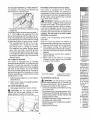
_DANGER:
This cutting
machine
is capable of ampLItating
hands
throwing
objects.
Failure to observe
the fol!owing
safety ,instructions
in serious injury or death.
INever dire_tldischaroed
material toward
!anyone. /_oid
discharging
material
tagainst a _iall or obstruction_ Material
Imay ricochet back toward the operator.
!Stop the'i_lades
when crossing gravel
i surfaces., i !i!
" Do not operate machine without the entire
grass catcher, or other safety devices in
place and working°
,
Slow down before turning°
,
Never leave a running machine unat:
tended. Always turn off blades, set parking brake, stop engine, and remove keys
before dismounting.
,
Disengage
blades when not mowing.
Shut off engine and wait for all parts to
come to a complete stop before cleaning
the machine, removing the grass catcher,
or unclogging the discharge guard.
• Operate machine only in daylight or good
,
artificial light,.
Do not operate the machine while under
the influence of alcohol or drugs°
° Watch for traffic when operating near or
crossing roadways.
" Use extra care when loading or unloading
the machine into a trailer or truck.
_WARNING:
In order to prevent accidental
starting when setting up, transporting, adjusting or making repairs, always disconnect
spark plug wire and place wire where it
cannot contact spark plug.
_WARN1NG:
Do not coast down a hill in
neutral, you may lose control of the tractor.
_WARNING:
Tow only the attachments
that are recommended
by and comply with
specifications
of the manufacturer
of your
tractor. Use common sense when towing.
Operate only at the lowest possible speed
when on a slope_ Too heavy of a load, while
on a slope, is dangerous°
Tires can lose
traction with the ground and cause you to
lose control of your tractor.
,_WARNING:
Engine exhaust, some of its
constituents, and certain vehicle components
contain or emit chemicals known tothe State
ofCaliforniatocause
cancerand birth defects
or other reproductive
harm.
_WARNING:
Battery posts, terminals and
related accessories
contain lead and lead
compounds, chemicals known to the State of
California to cause cancer and birth defects
or other reproductive
after handling.
I. GENERAL
,
•
,
,
,
•
,
harm.
Wash
and feet and
could result
hands
Always wear eye p rotectio n when o perating machine:
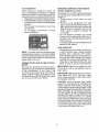
Data indicates that operators,
age 60
years and above, are involved in a large
percentag e of riding mower - related injuries, These operators should evaluate
! !their abilitytto operate the riding mower
safely enough to protect themselves and
others from serious injury,
recommem
° Follow the manufacturer's
dation for wheel weights or counterweights.
Keep machine free of grass , leaves
'
or other debris build - up which can
touch hot exhaust / engine parts and
burn. Do not allow the mower to plow
leaves or other debris which can cause
build - up to occur, Clean any oil or fue!
spillage before operating or storing the
machine. Allow machine to cool before
storage,
OPERATION
Read, understand, and follow all instructions on the machine and in the manual
before starting.
De not put hands or feet near rotating
parts or under the machine. Keep clear
of the discharge opening at all times.
Only allow responsible
adults, who are
familiar with the instructions,
to operate
the machine°
Clearthe area of objects such as rocks,
toys, wire, etc., which could be picked
up and thrown by the blades
Be sure the area is clear of bystanders
before operating. Stop machine if anyone
enters the area°
Never carry passengers.
Do not mow in reverse unless absolutely
necessary° Always look down and behind
before and while backing°
3
IDENTIFICA
Yea la seccil
!t, SLOPE
OPERATION
,
Never carry children,
even with the
blades shut off. They may fall off and be
seriously injured or interfere with safe
machine operation. Children who have
been given rides in the past may suddenly
appear in the mowing area for another
ride and be run over or backed over by
the machine,,
Slopes are a major factor related to loss of
control and tip - over accidents, which can
result in severe injury or death° Operation
on all slopes requires extra caution, if you
cannot back up the slope or if you feel uneasy
on it, do not mow iL
•
Mow up and down slopes, not across,
Watch for holes, ruts, bumps, rocks, or
" Never allow children to operate the meUneven terrain ........... chine.
............
other hidden objects.
could overturn the machine. Tall grass
" Use extra care when approaching
blind
corners, shrubs, trees, or other objects
can hide obstacles.
that may block your view of a child,
. Choose a low ground speed so that you
wilt not have to stop or shift while on the
IV. TOWING
slope.
• Tow only with a machine that has a hitch
.
Do not mow on wet grass, Tires may lose
designed for towing. Do not attach towed
traction.
equipment except at the hitch point.
Always keep the machine in gear when
• Followthemanufacturer'srecommendagoing down slopes., Do not shift to neutral
tion forweight limits for towed equipment
and coast downhill.
and towing on slopes.
. Avoid starting, stopping, or turning on a
• Never allow children or others in or on
slope. If the tires lose traction, disengage
towed equipment.
the blades and proceed slowly straight
• On slopes, theweight ofthe towed equipdown the slope_
ment may cause loss of traction and loss
,
Keep all movement on the slopes slow
of control.
and gradual.
Do not make sudden
- Travel slowly and allow extra distance to
changes
in speed or direction,
which
stop.
could cause the machine to roll over,
V, SERVICE
,
Use extra care while operating machine
with grass catchers or other attach ments;
SAFE HANDLING
OF GASOLINE
they can affect the stability of the maTo avoid personal injury or property damchine° Do no use on steep slopes,
age, use extreme care in handling gasoline.
.
Do not try to stabilize the machine by
Gasoline is extremely flammable
and the
putting your foot on the ground.
vapors are explosive,
o Do not mow near drop - offs, ditches,
.
Extinguish all cigarettes,
cigars, pipes,
or embankments.
The machine
could
and other sources of ignition.
suddenly roll over if a wheel is over the
° Use only approved gasoline container_
edge or if the edge caves in.,
.
Never remove gas cap or add fuel with
Iii. CHILDREN
the engine running, Allow engine to cool
before refueling
Tragic accidents can occur if the operator
•
Neverfuel the machine indoors.
is not alert to the presence
of children.
°
Neverstorethe
machine orfuel container
Children are often attracted to the machine
and the mowing activity. Never assume
that children will remain where you last
saw them.
• Keep children out of the mowing area
and in the watchful care of a responsible
adult other than the operator,,
• Be alert and turn machine off if a child
enters the area.
•
Before and while backing, look behind
and down for small children.
•
where there is an open flame, spark, or
pilot light such as on a water heater or
other appliances_
Never fill containers inside a vehicle or
on a truck or trailer bed with plastic liner.
Always place containers on the ground
away from your vehicle when filling.
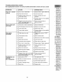
PROBLEI_
P#rdida de
continuadc
Vibraci6n
e
Et tractor st
en marcha
El motor co
funcionan c
cuando el e
se baja det
con el embl
del accesor
enganchadt
Ma corte - c
Las cuchill_
segadoras
_rvicioSears.
o
combustible,
AREL
,nde
s antesde
bie la bateria.
de aire.
mbustibleo
, combustible
a a llenar el
a nueva
nbustibleo
"ado,
rburador"
_io y Ajustes.
con un
_,rs O 00[1
url
Remove gas- powered equipment from
the truck or trailer and refuel it on the
ground, if this is not possible, then refuel
such equipment with a portable container,
rather than from a gasoline dispenser
nozzle.
•
Keep the nozzle in contact with the rim
of the fuel tank or container opening at
all times until fueling is complete. Do not
use a nozzle lock - open device.
•
If fuel is spilled on clothing, change clothing immediately.
o [--]ever overfill fuel tank_ Replace gas cap
and tighten securely.
GENERAL
SERVICE
.
•
) cualificado.
•
de aire.
.
•
.
•
Never operate machine in a closed area.
Keepallnutsandboltstighttobesurethe
equipment is in safe working condition,
NevertamperwithsafetydevicesoCheck
their proper operation regularly°
"
"
Keep maclfine4_ free of grass, leaves, or
other debris build - up. Clean oit or fue!
spillage and remove anyfuel- soaked debris. Allow machine to cool before storing.
If you strike a foreign object, stop and
inspect themachine.
Repair, if necessary,
before restarting,
Never make any adjustments
or repairs
with the engine running,
Check grass catcher components and the
discharge guard frequently and replace
with manufacturer's
recommended parts,
when necessary,
Mower blades are sharp. Wrap the blade
or wear gloves, and use extra caution
when servicing them.
Check brake operation frequently, Adjust
and service as required,
Maintain or replace safety and instruction
labels, as necessary,
ie la bateria.
mbustible.
_combustible
n gasolina
,ado,
_arburador"
o y Ajustes.
COn un
_rs o con
uR
3 cualificado.
freno,,
rague del
bie la bateria
de la bateria.
rado,
rruptor de la
.moide o
con
.
•
•
-
uP,
9.rs o OOl3 u13
cualificado.
bie la bateria.
Je ta bated&
rado.
.moide o
.
_e,
aceleraci6n.
,r de fa caja
°
Before and while backing, look behind
and down for small children.
Be sure the area is clear of bystanders
before operating. Stop machine if anyone
enters the area.
Never carry passengers.
Do not mowin reverse unless absolutely
necessary, Always look down and behind
before and while backing.
Never carry children,
even with the
blades shut off. They may fall off and
be seriously
injured or interfere with
safe machine operatiom
Children who
have been given rides in the past may
suddenly appear in the mowing area for
another ride and be run over or backed
over by the machine.
Keep children out of the mowing area
and in the watchful care of a responsible
adult other than the operator.
Be alert and turn machine off i-f a child
enters the area,
•
•
•
,
•
de aire.
._ite!cambie el
star la
bujfa,
5
Mow up and down slopes (15 ° Max), not
across.
Choose a low ground speed so that you
will not have to stop or shift while on the
slope_
: ,
Avoid starting, stopping, or turning on a
slope, If the tires lose traction, disengage
the blades and proceed slowly straight
down the slope°
If machine stops while going uphill, disengage blades, shift into reverse and
back down SlOWly.
Do nottum on slopes unless necessary,
and then, turn slowly and gradually down ....................
hill, if possible.
PRODUCT
REPAIR
SPECIFICATIONS
Gasoline Capacity
and ]_jpe:
1o50 Gallons
Unleaded Regular
Oil Type
API - SG - SL):
SAE 30 (above 32°F)
SAE 5W30 (below 32°F
Oil Capacity:
.....................
Wi Filter:
56 oz,.
W/O Filter: 48 ozo
Spark Plug:
Champion RC12YC
(Gap: .030")
Ground Speed
Forward:
.................................. Reverse:
Charging System:
Battery:
Congratulations on making a smart purchase.
Your new Craftsman@ product is designed
and manufactured
for years of dependable
operation. But like all products, it may require
repair from time to time. That's when having
a Repair Protection Agreement can save you
money and aggravation.
Purchase a Repair Protection Agreement
now and protect yourself from unexpected
hassle and expense..
0- 5.5
0- 2.4
Here's what's
3 Amps Battery
5 Amps Headlights
Amp/Hr:
Min. CCA:
Case size:
included
in the Agreement:
Expert service by our 12,000 profesional
repair specialists.
28
230
UIR
Unlimited service and no charge for parts
and labor on all covered repairs°
Product replacement if your covered
product can't be fixed,
Blade Bolt Torque: 45 - 55 Ft.. Lbs.
CONGRATULATIONS
on your purchase of
a new tractor. It has been designed, engineered and man ufactured to give you the best
possible dependability
and performance.
Should you experience any problem you cannot easily remedy, please contact a Sears or
other qualified service center. We have competent, well-trained
representatives
and the
proper tools to service or repair this tractor.
Please read and retain this manual, The
instructions
will enable you to assemble
and maintain your tractor properly. Always
observe the "SAFETY RULES"°
CUSTOMER
PROTECTION
AGREEMENTS
Discount of 10% from regular price of
service and service - related parts not
covered by the agreement; also, 10% off
regular price of preventive maintenance
check.
Fast help by phone- phone support from
a Sears representative
on products requiring in - home repair, plus convenient
repair scheduling,
Once you purchase
the Agreement,
a
simple phone call is all that it takes for you
to schedule service., You can call anytime
day or night, or schedule a service appointment online°
RESPONSIBILITIES
• Read and observe the safety rules
• Follow a regular schedule in maintaining,
caring for and using your tractor.
. Follow the instructions
under "Maintenance" and "Storage"
sections
of this
owner's manual.
Sears has over 12,000 professional repair
specialists,
who have access to over 4,5
million quality parts and accessories. That's
the kind of professionalism
you can count on
to help prolong the life of your new purchase
for years to come. Purchase your Repair
Protection Agreement today!
,_WARNING:
This tractor is equipped with
an internal combustion
engine and should
not be used on or near any unimproved
forest - covered, brush - covered or grass
- covered land unless the engine's exhaust
system is equipped with a spark arrester
meeting applicable
local or state laws (if
any). If a spark arrester is used, it should
be maintained in effective working order by
the operator.
Inthe state of California the above is required
by law (Section 4442 ofthe California Public
Resources Code). Other states may have
similar laws. Federal laws apply on federal
lands. A spark attester for the muffler is
available through your nearest Sears service
center (See REPAIR PARTS manual).
Some limitations
and exclusions
apply.
For prices and additional
information
call
1 - 800 - 827 - 6655.
SEARS
INSTALLATION
SERVICE
For Sears professional
installation of home
appliances,
garage door openers,
water
heaters, and other major home items, in the
U.S.A. call 1 - 800 - 4 - MY. HOME®
6
lnmediatame
macenamien
tractor no se
_ADVERTE
con gasolina
en d0nde los
expuesta o u
enfrie antes c
privado,
TRACTOR
Cuando el tr_
peri0do de t
quite toda la
Gu&rdela en
1. Limpieto
secci6n d
2_ Inspeccio
esario (w
de ]as cc
Ajustes d
3. Lubriquel
de Mante
4 Aseg_res
los tornillc
tnspeccio
si hay dat
es neces_
5 Retoque 1
o picadaE
BATERiA
• Cargue la
guardarla,
• Despu_s
almacenar
volver a ca
• Para ayud[
potencia d
namiento, I
la bateria
(vea "PAR/
MINALES"
este manu
• Despu6s
desconec
puedan en
de la bater
• Si se remt
almacenar
sobre con(
MOTOR
SISTEMA D[
IMPORTAN'I
man deposit,
tales del siste
carburador, e
del combustil
tide oomo ,
metanol) pu_
duce a la sep
durante elaln
puede daSar
motor durant_
i
I
hufable de 30
:lor del fusible
i
...............
O DEL CAPO
i .......
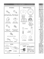
Steering
Bagger
Wheel
dambre de las
arre el cap6 en
_cia el motor y
asegerese de
Jel alambre de
%
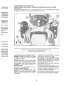
(6) 1/4 x 20 x 1,15
Shoulder Bolts
(8) t/4 x 20 x 1.25"
Carriage Bolts
Steering
Wheel
Wheel Insert
i
i
i
,
Conector deI
alambre de
las Luces
Delanteras
(10) 114x 20
(5) 114x 20
Square Nuts
Flange Lock Nuts
%
Steering
Boot
,r
(1) Bolt
(2) 1/4x 1,15"
i
(2) 1/4x 15 x 0.5"
Bosscrew
(Thread
Steering Wheel
i Adapter
Screw (Gold)
(Thread for plastic)
for plastic)
Steering
Extension
t
I
i
Shaft
i'
._ser removida
_=set purgada
_=sde operar el
}MISlON" en la
manual
t
(3) t/4 x 20 x 0,75" Bolt
CONTROL DE
preajustado en
_justes. Revise
:inuaci6n, antes
necesario, yea
Retainer Spring clip
Clevis Pin
Io en la f_,brica
in embargo, se
!or importancia
sen el combus-_iel carburador
de motor.
(1) Large
Flat Washer
(1) Lock
Washer
Seat
(1) Oil Drain Tube
For Future Use
DE
ido preajustado
ar ajustes.
DOR
'
(1) Washer
'k___
_
(1) Bolt
(I) Seat
Slope
Sheet
.......
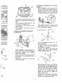
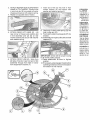
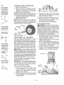
Your new tractor has been assembled at the factory with the exception of those parts left
unassembled
for shipping purposes° To ensure safe and proper operation of your tractor
al! parts and hardware you assemble must be tightened securely. Use the correct tools as
necessary to ensure proper tightness°
TOOLS
REQUIRED
FOR ASSEMBEY"
INSTALL STEERING WHEEL
....A socket wrench set will make assembly
easier. Standard wrench sizes are listed.
(t) 5/I6"
wrench
Utility knife
(2) 7/i 6" wrenches
(2) 1/2" wrenches
Tire pressure
Pliers
gauge
(1) 9/16" wrench
When right or left hand is mentioned in this
manual, it meanswhenyou
are in the operating
position (seated behind the steering wheel),
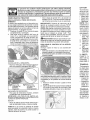
TO REMOVE
CARTON
UNPACK
TRACTOR
FROM
CARTON
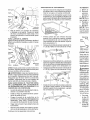
1. Remove all accessible loose parts and
parts boxes from carton,,
2. Cutalong dashed lines on allfour panels
of carton. Remove end panels and lay
side panels flat.
3. Check for any additional loose parts or
cartons and remove.
BEFORE REMOVING
FROM SKID
CHECK
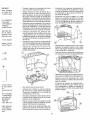
3.
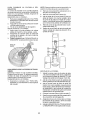
Position front wheels of the tractor so
they are pointing straight forward,
4o Remove steering wheel adapter from
steering wheel and slide adapter onto
..... steering shaft extension,
5. Position steeringwheelso
cross bars are
horizontal (left to right) and slide inside
boot and onto adapter_
6. Assemble
large flat washer, 5/16 lock
washer, 5/16 hex bolt and tighten securely.
7, Snap steering wheel insert into center of
steering wheel°
8. Remove protective materials from tractor
hood and grill.
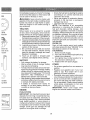
IMPORTANT:
Check for and remove any
staples in skid that may puncture tires where
tractor is to roll off skid°
ck
L°lnsertWasher
Bolt -_}_
TRACTOR
_c_---_Large
BATTERY
._.__.Steering
1, Lift seat pan to raised position.
NOTE: If this battery is put into service after
month and year indicated on label (label located between terminals) charge battery for
minimum of one hour at 6 - 10 amps. (See
"BATTERY"
in Maintenance
section of this
manual
Fla! Washer
for charging
Wheel
Steering
Boot
Adapter---_____,(_
_
Extension
_.___-_Shaft
Lower
\_( .....
Steering
_'P" ........
Shaft ____.,
k
'""---.-°",,
instructions),
Seat
I ./5_,;1_
-'%
Tab
{_P--'
':_"'_
Stot--"t_ [ _i./
INSTALL
STEERING
Rete_
ASSEMBLE
BOOT
EXTENSION
1. Slide extension
shaft.
2.
SHAFT AND
1'\
}
SEAT
3_ Place seat on seat pan so all three (3)
bottom pads are positioned
over large
slotted holes in pan.
4, Push down on seat to engage pads in
slots and pull seat towards rear of tractor,
5. Raise seat and tighten bolt securely,
shaft onto lower steering
Place tabs of steering boot overtab
in dash and push down to secure.
slots
B
'
',
Remove bolt and flat washer securing
seat to cardboard packing and set aside
for assembly of seat to tractor. Remove
the cardboard packing and discar&
2, Connect switch to seat.
WHEEL
PARA REMO
REPARAClO
1.. Bloquee
2. Remueva
ci6n y las
de ias rue
llave cuac
3. Repare la
AVISO: En la.,
las ranuras el
ejeo inserte la
4o Vuelvaac_
de retencid
5. Vuefva a c(
AVISO: Pare
prevenir que t
pequefias fuc
Sears y utilizer
que las Ilanta.,
Cubierta
del eje
t.
ATTACH
1_ Aparcar e
de hormic
el pedal c
el freno d
2. Desembn
mando de
misi6n de
rueda libr
asi se col
Las ruedas tr
tinar cuando
el tractor man
freno o contac
de servicio CL
Anillc
Terminal
Terminal
CONTROLAI
Si el tractor _
pararse a un_
mAs alto en u
seco o pavirn_
y ajustar eFfr(
CONTROL D
Llave Cuadrada
trasera solamer
IMPRESION 1
DELANTERA
La impresi6n
teras de sun
y son
normal
rJe las ruedas
caso que se F
impresi6n o I_
teras tel corn(
contacto con {
centro de sen
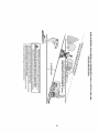
ransmisi6n y la
rdacorreas.
acionario (A) y
tral (C).,
oia la parte de
cuidado, retire
da de la trans)a y pas_,ndola
ventilador (D).
_1motor movi6te de atr&s del
direcci6n (F) y
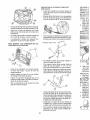
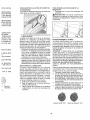
TO ASSEMBLE
Seat
switch
.
•
Slot
Seat
P
6_
Remove tape and discard.
Lower seat into operating position and
sit on seat° Press brake pedal all the
way down. If operating position is not
comfortable,
adjust seat.
TO ADJUST
•
SEAT
Grasp adjustment
handle and pull up, slide
seat to desired position and release adjustment handle.
Slot
•
Flat
washer
Seat
Bolt
Fee,
_6n central (C).
6n estacionario
(B),
calce en todas
_entro de todas
'ARA MONTAR
Jlo del manual).
First, align two holes as shown on side
of bagger frame upper weldment
(4)
with corresponding
holes in top bagger
frame tube (1).
Install two 1/4" - 20 x 1 25 carriage bolts
(5) and secure with two 1/4" nuts (6).
Tape
•
parte de atr&s
.-tor, pas&ndoia
._cciSn(F) y del
ue t freno (G)o
le adelante del
._adel motor (E)_
a de atr&s del
7ueva la correa
,r del ventilador
de la polea de
e la correa est6
Do not operate machine without the
entire grass catcher, or other safety
devices in place and working.
Feed top bagger frame tube (1)through
loop (2) atthetop of bagger fabric (leave
loop segments
on the ends loose).
Wiring harness
7.
®
BAGGER
pan
Tab
Adjustment
handle
•
NOTE: "You may now roll your tractor off
the skid. Follow the instructions
below to
remove the tractor from the skid.
Align two holes on opposite of bagger
frame upper weldment
(4) with corresponding
holes in top bagger frame
tube (1).
Install two 1/4" - 20 x 1.25 carriage bolts
(5) and secure with two 1/4" nuts (6).
,_kWARNING:
Before
starting,
read,
understand and follow all instructions in the
Operation section of this manual. Be sure
tractor is in a well - ventilated area. Be sure
the area in front of tractor is clear of other
people and objects_
TO ROLL
TRACTOR
OFF
SKID
Install two more carriage bolts (7) rearward on sides of top bagger frame tube,
hand tightening nuts (8).
(See
Operation
section
for location
and
function
of controls)
1. Raise attachment lift lever to its highest
position,
2. Release parking brake by depressing
brake pedal.
3 Place freewheel control in "transmission
disengaged" position" (See "TO TRANSPORT" in Operation section of manual),
4. Roll tractor forward off skid.,
5. Remove banding holding the deflector
shield up against tractor,.
Continue with the instructions that follow.
9
•
Lay bagger cover upside - down (leave
protective covering intact),.
.
Slide bagger
handle
insert
(9) into
depression
on inside of bagger cover,.
Make sure the two tabs at the top
lock into place with the bagger cover.
Teeth
at the bottom
of the bagger'
......................
handle insert should slide into place in
between the teeth on the bagger cover,
.
Slide two square nuts (10) into the two
square slots at the front of the bagger
cover and two square nuts into the two
square slots (one slot on each side) at
..........................
the- rear-, handle of the- bagger cove[:
. Turn bagger
assembly
(3) upside
down, lining up holes in the frame to
holes in the bagger cover, making sure
frame upper weldment tubing is seated
in plastic cradle in the bagger handle
insert (9).
•
Install four 1/4" hex bolts (!1) in holes
with four square nuts (10) and tighten
until seated°
•
•
•
Slide two 1\4" hex bolts (16) through
holes at top of the front bagger frame
and thread into nuts inside the tubing of
top bagger frame..
Slide plastic clip (17) down into bagger
fabric loop on right side and snap to front
bagger frame (I4) 101 mm (4 inches)
from top of front bagger frame tube.
PARA NIVEL
Aseg_rese de
ta PSI que se i
inflados o poc
bien cortado,
la SEGADOR
REGULACIO
1. Sitodoslc
inflados y
codado dq
cortadora
2. Con una
regulabte
tuerca de
para bajaJ
h&gala gil
para subi_
NOTA: Cada
ajuste her& va
madamente 3
Install two 1/4" screws (12) in holes at
center of frame upper weldment.
Haga girar la
°
•
,
°
.
•
•
Turn assembly right- side up.
Install two 1\4" carriage bolts (13) at
bottom of front bagger frame (I4), hand
tightening lock nuts (15).
Feed front
bagger
frame
(14) up
through fabric loops at front of bagger.
Snap bottom of front bagger frame (14)
into snap feature
at front of bagger
bottom.
•
•
Slide bagger fabric loop segments
at
the ends of bag onto top bagger frame
tubing.
•
10
Uninstall lock nuts (21) at rear of top
bagger frame and at bottom of front
bagger frame and attach cross braces
(22) on each side.
Reinstall lock nuts (21) and tighten until
fully seated.
Slide rubber seal (23) to top of metal
bagger handle (24).
Slide bagger handle (24) down through
bagger cover and frame upper weldment
holes.
Slide clevis pin (25) through hole at
bottom of bagger
handle
and slide
retainer spring (26) into hole at the end
of the clevis pin until it locks into place
tuerca f_acia!
la derecha
pare subir4a
segadora_
3.
Pruebe I_
c6sped q_
vando co
case nec,
satisfact#_
REGULAClOI
A LADO
1. Con todo
inflados, e
o en la en
CUIDADO:
las manos co_
con tela grue.,
2o Suba la S
3. A ambos
cuchilla h_
que hay e
y el suelo.
a ambos I
4,. En caso q_
lea los pa_
laci6n Vis_
Jela piezade
encuentra
en
_ra(H),y fijelo
' unresortede
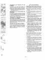
TO INSTALL
BAGGER
FULL LEVER/
PADD_LE
i
"
Before installation,
tractor engine must
be shut off and parking brake engaged.
•
Standing behind the tractor with the
bagger removed
from the backplate
(I), identify the bag full switch (2) area..
_.iiI
_..
.
embrague (Q)
•
3ntrae! soporteo
_rencima de la
e la correa (G).
•
,
Push plastic closeout (27) back so
it snaps into place behind retaining
(28).
Line up holes in grass deflector
with bosses in bagger cover°
First install 1/4" hex bolt (30) into
side as shown.
_"
that
ribs
(29)
Take bagger full lever (3) and insert
tab(4) into upper slot and rotate until
lever (3) snaps into position.
the
Then install 1/4" hex bolt (31) into the
top as shown.
TO INSTALL BAGGER
TO TRACTOR
_'L.
Front Qf Tractor
COMPONENT
rea encaje bien
:te lacortadora.
la posici6n de
:liras de l calibre
_iento la cortaitulo de Manejo
.
•
•
,
'
,
,
Before installation, tractor engine must
be shut off and parking brake engaged.
Install latch springs
(1) in mounting
holes on back plate,
Insert hex bolt (2) through each latch
spring hole and corresponding
hole in
back plate.
Fasten lock nut (3) to bolt on the other
side of back plate.
•
........
•
--.............
•
@
11
For the heaviest/wet
grasses,
do not
attach paddle (5),,
For lighter grasses use the paddle (5)
on setting "1 ", "2", or "3" ("3" being for
the lightest or dry grass)°
Choose
your setting and rotate the
bagger paddle (5) so that the desired
number (setting) faces you°
Place paddle (5) on lever (3) so that tab
(6) at the bottom of the bagger full lever
(3) goes through appropriate rectangular
slot and make sure holes in bagger
full lever (3) and paddle (5) line up.
Feed screw
(7) through
bagger full
paddle
(5) and lever (3) holes and
fasten using nut (8).
....................................
Setting may be changed by loosening
fasteners
(7 and 8), removing!rotating
paddle (5), and tightening again.
CHECK
TIRE
PRESSURE
_#fCHECKLIST
The tires on your tractor were overinflated
at the factory for shipping purposes. Correct
tire pressure is important for best cutting
performance,
• Reduce tire pressure to PSI shown on
..........i
ill-tires ..................... i.................
.
Please
CHECK
DECK
For best
should be
MOWER"
section of
cutting results, mower housing
properly leveled. See "TO LEVEL
in the Service and Adjustments
this manual.
CHECK
FOR
ALL BELTS
Before you operate your new tractor, we
wish to assure that you receive the best
performance
and satisfaction
from this
Quality Product.
LEVELNESS
PROPER
POSITION
OF
See the figures that are shown for replacing
motion and mower blade drive belts in the
Service and Adjustments section ofthis manual. Verify that the belts are ['outed correctly.
CHECK
BRAKE
SYSTEM
After you learn how to operate your tractor,
check to see that the b rake is operating properly. See"TO CHECK BRAKE" in the Service
and Adjustments
section of this manual.
review the following
_/All
assembly
completed.
_/No
remaining
checklist:
instructions
have
been
loose parts in carton.
J'Battery
is properly
prepared
and
..... charged,_
v/ Seat is adjusted comfortably
and tightened securely,,
_/f All tires are properly inflated. (For shipping purposes, the tires were overinflated
at the factory).,
_if Be sure mower deck is properly leveled
side - to - side/front - to - rear for best
cutting results. (Tires must be properly
inflated for leveling)°
Check mower and drive belts, Be sure
they are routed properly around pulleys
and inside all belt keepers.
vf Check wiring. See that all connections
are still secure and wires are properly
clamped.
_if Before driving tractor, be sure freewheel
control is in "transmission
engaged"
position (see "TO TRANSPORT"
in the
Operation section of this manual).
1,
2,
3,
4,
5.
6,
ADVER'I
ClO O D
Presion_
Ponga ia
Ponga e
Ponga fa
AsegOre_
Descone
PARA DI=SM,
ClaSPED
1, Suelte elE
"DISENGJ
2, Baje la p_
posici6n c
3, Ruede la
fijadors dE
4 Paraquital
5o Retire elr
dei brazo
6_ Desconec
la cortado
y la arand
7, Porunode
el brazo c
del chasis
la barra p,
los resort_
,_ CUIDAD(
piezas de unid
funcionar_, a r_
elevadora al c
While learning how to use your tractor, pay ex
-tra attention to the fotlowing important items:
Engine oil is at proper level.
Jf
Fuel tank is filled with fresh, clean, regular
unleaded gasoline.
J Become familiar with all controls, their
location and function.
Operate
them
before you start the engine.
_/ Be sure brake system is in safe operating
condition.
Be sure Operator Presence System and
Reverse Operation System (ROS) are
working properly (See the Operation and
Maintenance sections in this manual),.
_/ It is important to purge the transmission
before operating your tractor for the first
time° Follow proper starting and transmission purging instructions (See "TO START
ENGINE and PURGETRANSMISSION
in the Operation section of this manual).
12
(
J
or corroido y el
aquipado) pues
dio y!o dafios.
, de cada temada 100 horas
tero. El tipo de
arecen en "ESJCTO" secci6n
LINEA
biarse una vez
-ombustible se
"nbustible hacia
iarlo_
Efiltro y tapone
_ombustibleo
e nuevo
ell
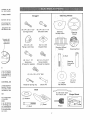
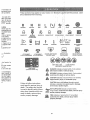
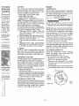
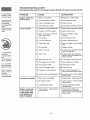
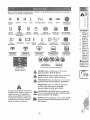
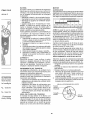
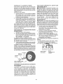
These symbols
and understand
R
N
REVERSE
NEUTRAL
ENGINE OFF
LIGHTS ON
REVERSE
OPERATION
SYSTEM (ROS)
FUEL
supplied
H
L
IXi
i'@,
HIGH
LOW
CHOKE
FAST'
Q #
SU
bustible con la
burador.
_n fugas en la
s grapas est6n
may appear on your tractor or in literature
their meaning.
8
ENGINE ON
ENGINE START
SLOW
IGNITION
SWITCH
@
I
PARKING
Learn
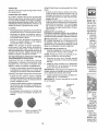
@
@,
8
BATTERY
with the product,
BRAKE!
fltOWER
HEIGHT
MOWER
LIFT
i
I' f
REVERSE
FORWARD
CRUISE
CONTROL
CLUTCHIBRAKE
PEDAL
a,
a gasolina der-
i
Abrazadera
ATTACHMENT
CLUTCH DISENGAGED
ATTACHMENT
CLUTCH ENGAGED
DO NOT OPERATE
WITHOUT BAGGER
@@®®®
, del motor, la
:C,
as y tas ruedas
te, etc..
s con cera tipo
OPERATE ONLY
WITH BAGGER
DANGER, KEEP HANDS
ANDFEETAWA¥
KEEP AREA CLEAR
i ,
(SEE SAFETY
(Automatic
Models only)
FREE WHEEL
,_una mangue_ara limpiar el
la transmisi6n
los del agua.
si6n acortan la
_mprimido o un
hierba, hojas y
SLOPE HAZARDS
RULES SECTION)
&
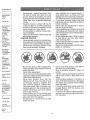
DANGER indicates a hazard which, if not avoided,
will result in death or serious injury.
&
WARNING indicates a hazard which, if not avoided,
could result in death or serious injury.
•
,j
CAUTION indicates a hazard which, if not avoided,
might result in minor or moderate injury.
q i
Failure to follow instructions
could result in serious injury or
death.. The safety alert symbol
is used to identify safety information about hazards which can
result in death, serious injury
and/or property damage.
CAUTION when usedwithout the alert symbol,
indicates a situation that could result in damage
to the tractor and/ol"engineo
;
HOT SURFACES indicates a hazard which,
if not avoided, could result in death, serious injury
,,,,tf_,_,_,,,,,
and/or property damage.
.......
FIRE indicates a hazard which, if not avoided,
/_,
could result in deat h, serious injury and/or
....... property damage.
13
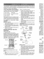
KNOW
YOUR
TRACTOR
READ THIS OWNER'S
TRACTOR
MANUAL
AND
SAFETY
RULES
BEFORE
OPERATING
YOUR
Compare the illustrations with your tractor to familiarize yourself with the locations
various controls and adjustments.
Save this manual for future reference,
of
BATERiA
Su tractor cue
bateria que e_
embargo, si s_
con un carga(
su duraci6n.
• Mantenga I
• Mantenga I
• Mantenga I
flos abieflo
• Vuelva a ca
AVlSO: La b
tractor no be(
remover las t_
a_,adir o verifi,
PARA L1MPIAI
La corrosi6n
terminales pu,
cia en la batel
1, Desconec
primero y
y remuev_
2, Enjuague
s6quelao
3. Limpie los
de la batel
que qued_
4. Cubra los
5, Reinstale
Baleria" e
de este m
CORREAS V
Revise las c_
deterioro y d_
operaci6n y c
reas no son
empiezan a d
Our tractors
conform
American
to the applicable safety standards
National Standards Instituter
of the
(A) ATTACHMENT
LIFT LEVER - Used to
raise and lower the mower or other attachments mounted to your tractor,
(G) R EVERSEOP ERATIO N SYSTEM (ROS)
"ON" POSITION -Allows operation of mower
or other powered attach merit while in reverse°
(B) BRAKE PEDAL
- Used braking
tractor and starting the engine.,
(H) LIGHT SWITCH
on and off.
the
- qqJrns the headlights
- Locks brake pedal
(K) FORWARD
DRIVE PEDAL
forward movement of tractor,
- Used for
(D) THROTTLE/CHOKE
CONTROLUsed
for starting and controlling engine speed°
(L) REVERSE
DRIVE PEDALreverse movement of tractor.
Used for
(E) ATTACH M ENT CLUTCH LEVER - Used
to engage the mower blades, or other attachments mounted to your tractor_
(M) FREEWHEELCONTROLDisengages
transmission
for pushing or slowly towing
the tractor with the engine off,
(C) PARKING BRAKE
into the brake position.
(F) IGNITION SWITCH _ Used for starting
and stopping the engine,
14
ENFRIAMIEI_
Las afetas de
transmisi6n Ii_
asegurar el el
No trate de lit
cuando el mo
transmisi6n e
• Inspeccion_
asegurarse
intactas y li
• lnspeccion,
verificar si
otros mate
juntas, no u
o de alta I:
enfriamient
NiVEL DEL F
Et transeje h
mantenimient
vida del trans
se filtrase onc
ponerse en c
Sears o con uJ
,]IENTO ATR,&,S
The operation
of any tractor can result in foreign objects thrown into
the eyes, which can result in severe eye damage. Always wear safety
glasses or eye shields while operating
your tractor or performing
any
adjustments
or repairs. We recommend
standard
safety glasses or a
wide vision safety mask worn over spectacles.
"ha con et intemotor "ON" y el
:tado, cualquier
r marcha atr_.s,
"ha con e! inteFuncionamiento
"y el embrague
lquier tentativa
atrb,s, NO apa-
las cuchillas de
Reemplace las
_daso daSadas.
_ente la hojas
bricante de su
tprobada por el
etigroso, puede
J garantia.
HOW
TO
USE YOUR
TO SET PARKING
TRACTOR
, Turn ignition key (F) to "STOP" position
and remove key.Always remove keywhen
leaving tractor to prevent unauthorized use.
. Never use the choke to stop the engine.
BRAKE
Your tractor is equipped with an operator
presence sensing switch. When engine is
running, any attempt bythe operator to leave
the seat without first setting the parking brake
will shut off the engine.
1_ Depress brake pedal (B) allthe way down
and hold.
2. Pull parking brake lever (C) up and hold,
release pressure from brake pedal (B),
then release parking brake lever. Pedal
should remain in brake position, Make
sure parking brake will hold tractor secu re.
IMPORTANT:
Leaving the ignition switch in
any position other than "STOP" will cause
the battery to discharge and go dead.
NOTE: Under certain conditions when tractor
is standing idle with the engine running, hot
engine exhaust gases may cause "browning" of grass. To eliminate this possibility,
always stop engine when stopping tractor
on grass areas.
CAUTION:
Always stop tractor completely, as described above, and set parking
brake before leaving the operator's position,
sici6n m_s alta
cuchiilas.
TO USE THROTTLE
_luantes y/o enuesa.
Jchilla dandole
al de tas agujas
el estampado
ion de la segariL
instalacion apral de la cuchilla
_andrii.
cuchi!la firme;).
._1de la cuchilta
CONTROL
(D)
Always operate engine at full speed (fast)_
• Operating engine at less than full speed
(fast) reduces engine's operating efficiency_
. Full speed (fast) offers the best mower
performance,
STOPPING
MOWER
BLADES
-
• To stop mower blades, move attachment
clutch lever to disengaged position (r_),
TO MOVE FORWARD
_,onjunto del
Vfandril
(,_r_'3)Attachment
Clutch Lever
"Engaged"
GROUND
(r_'l)Attachment
Clutch Lever
"Disengaged"
DRIVE-
, To stop ground drive, depress brake pedal
into full "BRAKE" position.
IMPORTANT:
FORWARD
AND
REVERSE
DRIVE PEDALS RETURN TO NEUTRAL POSITION WHEN NOT DEPRESSED.
ENGINE
AND
BACKWARD
The direction and speed of movement
is
controlled by the forward and reverse drive
pedals,
1. Start tractor and release parking brake
2, Slowly depress forward(K) or reverse (L)
drive pedal to begin movement. Ground
speed increases the further down the
pedal is depressed,
-
• Move throttle control (D) between half and
full speed (fast) position.
NOTE: Failure to move throttle control between half and full speed (fast) position, before stopping, may cause engine to "backfire".
I5
TO ADJUST
MOWER
CUTTING
The position of the attachment
determines the cutting height+
HEIGHT
REVERSE
lift lever (A)
TO OPERATE
clutch control.
CAUTION:
Do not operate machine
without the entire grass catcher, or other
safety devices in place and working
16
PRO(;.
MANTI
Revisar la oper;
Revisar
I_ presi,
up with the atA
I Revi_r
C
I Alilaricambiar
s} b.a_"
0
I Revisar el nivel
1_
R ILimpi_r
la baler
Revisar
el en|ri_
Gc.t'npruobe L_ t_
fnspeccbne
ta_
Revisar el nivef
OPERATION
Carnbtar el ac_l
Engine "ON" Position
(Normal Operating)
ON HILLS
WARNING:
Do not drive up or down
hills with slopes greater than I5 ° and do not
drive across any slope. Use the slope guide
provided at the back of this manual.
, Choose the slowest speed before starting
up or down hills.
, Avoid stopping or changing speed on hills.
• If stopping is absolutely necessary, push
brake pedal quickly to brake position and
engage parking brake.
• To restart movement, slowly release parking brake and brake pedal.
, Slowly depress appropriate drive pedal to
slowest setting°
, Make all turns slowly.
attach+
BLADE
attachment
REVERSE
ROS "ON" Position
1, Select desired height of cut with attachment lift iever_
1. Disengage
Backing
Only use if you are certain no children or
other bystanders will enter the mowing area.
1+ Depress brake pedal all the way down,
2. With engine running, turn ignition key
counterclockwise
to RQS "ON" position,,
3. Look down and behind before and while
backing.
4° Slowly depress reverse drive pedal to
start movement.
5. When use of the ROS is no longer
needed, turn the ignition key clockwise
to engine "ON" position.
MOWER
MOWER
WARNING:
USING
THE
SYSTEM -
Your tractor is equipped with an operator
presence sensing switch° Any attempt by the
operator to leave the seat with the engine
running and the attachment clutch engaged
will shut off the engine. You must remain
fully and centrally positioned in the seat to
prevent the engine from hesitating or cutting
offwhen operating your equipment on rough,
rolling terrain or hills.
TO STOP
(ROS)
tachment clutch engaged while mowing is
strongly discourage& Turning the ROS "ON",
to allow reverse operation with the attachment clutch engaged, should only be done
when the operator decides it is necessary to
reposition the machine with the attachment
engaged. Do not mow in reverse unless
absolutely
necessary..
o Put attachment
lift lever in desired cutting
' height sloto
The cutting height range is approximately
1"
to 4'L The heights
are measured
from the
ground to the blade tip with the engine not running, These heights are approximate
and may
vary depending upon soil conditions, height
of grass and types of grass being mowed,,
• The average lawn should be cut to approximately
2-1/2 " during the cool season and to over 3 " during hot months,,
For healthier and better looking lawns,
mow often and after moderate growth°
. For best cutting performance,
grass over
6" in height should be mowed twice, Make
the first cut relatively high; the second to
desired height.
2. Start mower blade by engaging
ment clutch control,
SYSTEM
Your tractor is equipped
with a Reverse
Operation System (ROS). Any attempt by
the operator to travel in the reverse direction
with the attachment clutch engaged will shut
off the engine unless ignition key is placed
in the ROS "ON" position.
_,
TO OPERATE
OPERATION
M ,'Cambia[
elUt_!
0 |Llmp{ar
T i Limpi+r
e! liltru
+
r"
t. rej+lla
Or
tnsp_.cCionar
t amorlir_uado,
el
[Jr
R
I Cambiar
el fill_o
Llmpiar
las _1_11
Cambt_r
la bulf_
! Carnb_tr el fill_
I- Cambiar m_._ a r
arnblont_s con a_
2+ Dar servicie rn,_s
o potvotosas
RECOMENI
La garant[a dt
que han esta¢
cia del opera
la garantia, e
segadora se_
este manual,
Hay algunos
forms peri6di,
adecuadame{
Ai menos un
si es necesal
en las seccio
manual,,
• Unavezal
bie et filtro
correas est
un filtro de +
aire- comb
su motor fL
ANTES DE
1. Revise el
2. Revise la
3. Revise la
4 Verifique
operado
adecuata_
5 Revise si
f
BEFORE
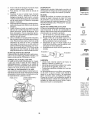
TO TRANSPORT
When pushing or towing your tractor, be
sure to disengage transmission
by placing
freewheel
control in freewheeling
position°
Freewheel control is located atthe of tractor,
CHECK
TRANSMISSION
ENGAGED
CARTS
AND OTHER
OIL LEVEL
ADD GASOLINE
• Fill fuel tank to bottom of filler neck. Do not
DISENGAGED
overfill. Use flesh, clean, regular unleaded
gasoline with a minimum
of 87 octane.
(Use of leaded gasoline will increase carbon and lead oxide deposits and reduce
valve life). Do not mix oil with gasoline, Purchase fuel in quantities that can be used
within 30 days to ensure fuel freshness,
NOTE: To protect hood from damage when
transporting your tractor on a truck or a trailer,
be sure hood is closed and secured to tractoro
Use an appropriate means of tying hood to
tractor (rope, cord, etc..)
TOWING
MENTS
ENGINE
THE ENGINE
The engine in your tractor has been shipped,
from the factory, already filled with summer
weight oil.
1. Check engine oil with tractor on level
ground°
2o Remove oil fill cap/dipstick
and wipe
clean, reinsertthe dipstick and screw cap
tight, wait for a few seconds, remove and
read oil level. If necessary, add oil until
"FULL'.' mark on dipstick is reached° Do
not overfill, t
• For cold weather operation you should
change oil for easier starting (See the oil
viscosity chart in the Maintenance section
of this manual),
• To change engine oil, see the Maintenance
section in this manual.
1. Raiseattachmentlifttoitshighestposition.
2. Pull freewheel control out and into the slot
and release so it is held in the disengaged
position.
,
Do not push or tow tractor at more than
two (2) MPH.
, To re-engage
transmission,
reverse
above procedure,
TRANSMISSION
STARTING
ATTACH-
_,CAUTION:
Wipe off any spilled oil or fuel,
Do,not store, spill or use gasoline near an
open flame.
:
Tow only the attachments
that are recommended by and comply with specifications
of the manufacturer
of your tractor. Use
common sense when towing Too heavy of
a load, while on a slope, is dangerous. Tires
can lose traction with the ground and cause
you to lose control of your tractor.
IMPORTANT:
When operating in temperatures below 32°F (0°C), use fresh, clean
winter grade gasoline to help ensure good
cold weather starting.
CAUTION:
Alcohol blended fuels (called
gasohol or using ethanol or methanol) can
attract moisture which leads to separation
and formation of acids during storage. Acidic
gas can damage the fuel system of an engine
while in storage. To avoid engine problems,
the fuel system ' should be emptied before
storage of 30 days or longer. Drain the gas
tank, start the engine and let it run until the
• fue! lines and carburetorare
empty. Use fresh
fuel next season° See Storage Instructions
....... for additional information. Never use engine
or' carburetor cleaner products in the fuel tank
or permanent damage may occur°
k:i
17
..............................
•
TO START
ENGINE
NOTE: If at a high altitude (above 3000
feet) or in cold temperatures
(below 32 F)
the carburetor fuel mixture may need to be
adjusted for best engine performance
(see
"TO ADJUST CARBURETOR"
in the Service
and Adjustments
section of this manual),
When starting the engine for the first time or
if the engine has run out of fuel, it will take
extra cranking time to move fuel from the
tank to the engine.
1. Be sure freewheel control is in the transmission engaged position_
2.
3.
4.
PURGE
Sit on seat in operating position, depress
brake pedal and set parking brake.
Move attachment
position_
Move throttle
_CAUTION:
Never engage or disengage
freewheel lever while the engine is running.
clutch to disengaged
To ensure proper operation and performance,
it is recommended
that the transmission
be
purged before operating tractor for the first
time. This procedure will remove any trapped
air inside the transmission which may have
developed during shipping of your tractor,
control to choke position.
NOTE: Before starting, read the warm and
cold starting procedures below.
5.. Insert key into ignition and turn key
clockwise to start position and release
key as soon as engine starts. Do not run
starter continuously for more than fifteen
seconds per minute. If the engine does
not start after several attempts, move
throttle control to fast position, wait a
few minutes and try again. If engine still
does not start, move the throttle control
back to the choke position and retry
WARM WEATHER STARTING
IMPORTANT:
Should your transmission
require removal for service or replacement.
it should be purged after reinstallation before
operating the tractor.
I.
Place tractor safely on a level surface that is clear of objects and open - with
engine off and parking brake set°
2.
Disengage
transmission
by placing
freewheel control in disengaged position
(See "TO TRANSPORT'
in this section
of manual).
(50°F (10 ° C) and above)
6. When engine starts, move the throttle
control to the fast position.
•
3.
The attachments
and ground drive can
now be used. If the engine does not
accept the load, restart the engine and
allow it to warm up for one minute using
the choke as described above_
COLD WEATHER
STARTING
4.
6. When engine starts, leave throttle control
in choke position until engine warms up
and begins to run roughly. Once rough
running begins, immediately
move the
throttle control to the fast position. Engine
warm-up may take from several seconds
to several minutes (the colder the temperature, the longer the warm-up).
TRANSMISSION
WARM
Sitting in the tractor seat, start engine.
After the engine is running, move throttle
control to stow position. Disengage parking brake.
&CAUTION:
At any time, during step 4,
there may be movement of the drive wheels.
(50°F (10 ° C) and below)
AUTOMATIC
TRANSMISSION
UP
5.
Shutoff
6.
Engagetransmissionby
pfacingfreewheel
control in engaged position (See "TO
TRANSPORT"
in this section of manual),
7.
Sitting in the tractor seat, start engine,
After the engine is running, move throttle
control to half (1/2) speed. Disengage
parking brake.
8.
Drive tractor forward for approximately
five feet then backwards for five feet. Re-
Before driving the unit in cold weather, the
transmission should be warmed up as follows:
1. Be sure the tractor is on level ground,
2.
Release the parking brake and let the
brake slowly return to operating position.
3. Allow one minute for transmission
to
warm uF This can be done during the
engine warm up period.
. The attachments can also be used dur-
Depress forward drive pedal to full forward position and hold forfive (5) seconds
and release pedal. Depress reverse drive
pedal to full reverse position and hold
for five (5) seconds and release pedal.
Repeat this procedure three (3) times,
engine and set parking
peat this driving
procedure
three times.
Your transmission
is now purged
ready for normal operation_
ing the engine warm-up period after the
transmission
has been warmed up,,
18
brake.
and now
PARA HACI
AI hacer arran
se ha acabadc
itar& tiempo p_
combustible c
1, AsegOres_
en la post,
2o Si6ntase
aci6n, su{
freno de e
3, Mueva e
posici6n o
4, Mueva la
a ia posici
AVlSO: Antes
guientes para_
5_ Insertelai
el sentido
posici6n d
pronto cot
cionar el
dequince
arranca dE
el control
r&pido, es
de nuevo
mueva el
posici6n d,
ARRANQUE !
(50°F(I0°C)
6, Cuando a
de ]a acel,
• Los accesc
set utilizadc
vuelva a arl
se caliente
gulador cor
ARRANQUE I
(50°F(10°C) "_
6, AI hacer
control de
trangulaci
empieze ft
a funcion_
control de
El calenta
partir de \
(cuanto m
es el calel
CAR EL MODE[. MOTOR
tviado desde la
d para verano,,
3n el tractor en
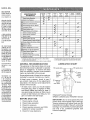
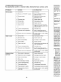
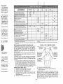
MAINTENANCE
SCHEDULE
BEFORE
EVERY
EACH
8
HOURS
USE
T
R
A
C
T
0
R
,, debe cambiar
m&s f#,cilmente
,_IAceite" en la
_ste manual)°
r,vea la secci6n
_uat,
][e., Llene hasta
relleno del eslemasiado, Use
,=vay limpia con
tso de gasolina
6sites de 6xido
la duraci6n de
con la gasolina,,
a utilizada sea
cuales puedan
_eros 30 dias,,
teo el combusderrame o use
cesta,,
•e en temperatse gasoline de
_dara asegurar
nezctados con
ol, o el uso de
;r la humedad,
y formaci6n de
to. La gasoline
Jel combustible
tamienta. Para
se debe vaciar
le guardarlo por
cie el estanque
motor y h_,galo
_ombustible y el
_xima tempora;s lnstrucciones
&s informaci6n,
pare el motor o
del combustible
; permanenteso
Check Tire Pressure
Check.Operail:)_"
PresRnce
EVERY
50
HOURS
EVERY
t00
HOURS
EVERY
SEASON
BEFORE
STORAGE
6/
Check Brake Operation
dora de nivel de
,uelva a inserter
atornille la tape
spere por unos
ray lea el nivet
agregue aceite
) la marca lleno
de niveL No to
EVERY
25
HOURS
./6/
&
ROS
Syslemfl
Check for Loose Fasteners
Chec!'JReplace
Mower Blades
Lubrication Chart
6/'_
e,"
.....................
Clean Battery and Terminals
j,,
v'
Cheek Transaxle Cooling
v'
Check
Battery
Level
.....................
v"
Check Mower Levelness
Cheek V-Belts
C,h,eck Engine Oil Level
............
Chancle Engine Otl (with oli filter)
El Change Engine
Ott (wtlhout
oil filter)
....
6'f_,a
N Clean Air Filter
_
el Clean Air Screen ............................................
V_'_
i inspect Mu![ler!Spa;k Ar[e2!er
.................................
.............................
6/
N:_Replace Oil Filter (If equipped)
E iClean Engine Cooling Fins
_
ReplaeD Spa rk P!ug
Replace Air Filler
Paper Cartridge
.....................
2
_
I
:
6/
Replace Fuel Filler
6/'
1 - Change, mere otlen when o{:_eratlng under a heavy lead or
in high ambient lemperalures
2 - Service more olfen when operating in dirty or dusty conditions
GENERAL
3 - Replace blades more often when mowing in sandy soil
4 - Not required i! equipped wilh matntenance-lree
batlery
LUBRICATION
RECOMMENDATIONS
The warranty on this tractor does not cover
items that have been subjected to operator
abuse or negligence.
To receive full value
from the warranty, operator must maintain
tractor as instructed in this manual.
CHART
(_ Spindle Zerk---]f-----_r----_
® ront
_-'i_[ .,
_) Spindle Zerk
.
...... ===
-
w.
o, ..4
.....
Bearing
_- ...... _
Some adjustments will need to be made periodically to properly maintain your tractor.
At least once a season, check to see if
you should make any of the adjustments
described in the Service and Adjustments
section of this manual.
@ Steering /
_-
...
Gear Teeth
_'_'"i\_
i @ Engin
i ii i
:"
*,:
i
:"
ii i
-
Ft',
(bGeneral Purpose Grease
@Refer to Maintenance
"ENGINE"
EACt4 USE
Front"
iBearing
hee,
Sector
At least once a year you should replace
the spark plug, clean or replace air filter,
and check blades and belts for wear. A
new spark plug and clean air filter ensure
proper air-fuel mixture and help your engine run better and last longer.
BEFORE
.......
[t,_z
Section
IMPORTANT:
Do not oil or grease the pivot
points which have special nylon bearings,
Viscous lubricants will attract dust and dirt
that wilt shorten the life of the self-lubricating
bearings, if you feel they must be lubricated,
use only a dry, powdered
graphite type
lubricant sparingly.
1, Check engine oil level.
2_ Check brake operation,
3.
4.
Check tire pressure.
Check operator presence and ROS
systems for proper operation,
5. Check for loose fasteners_
19
TRACTOR
CHECK
REVERSE
SYSTEM
Always observe safety rules when performing
any maintenance,.
BRAKE OPERATION
..........
.
Maintain proper air pressure in all tires
(See the sides of tires for proper PSI).
• Keep tires free of gasoline, oil, or insect
control chemicals which can harm rubber.
• Avoid stumps, stones, deep ruts, sharp
objects and other hazards that may cause
tire damage.
NOTE: To seal tire punctures and prevent
fiat tires due to slow leaks, tire sealant may
be purchased from your local parts dealer.
Tire sealant also prevents tire dry rot and
corrosion.
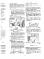
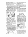
BLADE
SYSTEM
AND
gaged position.
CHECK
SYSTEM
OPERATOR
PRESENCE
. When the engine is running,
by the operator to leave the
first setting the parking brake
off the engine.
• When the engine is running
tachment clutch is engaged,
by the operator to leave the
shut off the engine.
• The attachment clutch should
ate unless the operator is in
any attempt
seat without
should shut
Slar
Center Hole
and the atany attempt
seat should
never operthe seat.
Blade Bolt
Mandrel
(Special) "_-_),_""
Assembly
Blade
@
ROS "ON" Position
REMOVAL
1o Raise mowerto highest position to allow
access to blades.
NOTE: Protect your hands with gloves and/
or wrap blade with heavy cloth.
2. Remove blade bolt by turning counterclockwise_
3, Install new blade with stamped "GRASS
SIDE" facing the ground°
IMPORTANT:
To ensure proper assembly,
center hole in blade must align with star on
mandrel assembly_
4. Install and tighten blade bolt securely
(45 - 55 Ft. Lbso torque).
IMPORTANT:
Special blade bolt iS heat
treated.
REVERSE OPERATION
SYSTEM (ROS)
Be sure operator presence
and reverse
operation systems are working properly. If
your tractor does not function as described,
repair the problem immediately_
. The engine should not start unless the
brake pedal is fully depressed,
and the
attachment clutch control is in the disen-
Engine "ON" Position
(Normal Operating)
20
PARA AJUS'f
LA SEGADOI
La posiciSn de
a qu6 altura s,
::;;:_!i!_i!!!:i
CARE
For best results mower blades must be sharp,.
eplace worn, bent or damaged blades.
CAUTION:
Use only a replacement
blade approved by the manufacturer
of your
tractor. Using a blade not approved by the
manufacturer
of your tractor is hazardous,
could damage your tractor and void your
warranty.
BLADE
PRESENCE
(ROS)
" Whentheengineis
runningwiththe
ignition
switch in the engine "ON" position and the
attachment clutch engaged, any attempt
by the operator to drive in reverse should
shut off the engine,
• When the engine is running with the ignition
switch in the ROS "ON" position and the
attachment clutch engaged, any attempt
by the operator to drive in reverse should
. NOT shut off the engine°
if tractor requires more than five (5) feet to
stop at highest speed in highest gear on a
level, dry concrete or paved surface, then
brake must be serviced., (See "TO CHECK
BRAKE" in the Service and Adjustments
section of this manual).
TIRES
OPERATOR
OPERATION
• Coloque la
la altura de,.
La gama de I;
damente 1 a
desde el sue!{
el motor no e_
aproximadas
condiciones d
del tipo del c6
• El c6sped p_
mente a 2 fria y sobn
calurosos_ f
able y de rr
y despu6s
, Para obten_
c6sped que
debe segars
ativamente
PARA OPERt
Su tractor vie
sensor que el
el motor estb. t
cesorio est& e
bajarse del as
que mantene
mente en et
vacile o se ap
en terreno dis
t. Seleccion,
2_ Baje la s_
tamiento c
3. Haga arra
engancha
accesorio_
tos extrafios
Siempre use
._resu tractor
: seguridad o
la posici6n de
ltave al abando, no autorizado.
erruptor de la
ra que "STOP"
gue (muerta).
cuando el traclando en vacio,
:aliente pueden
a "car6." Pare
e pare el motor
'on c_sped..
,_el tractor comanteriormente,
Jel operador.
LA ACELERa aceleraci6n
:idad inferior ala
tto disrninuye.
_eala velocidad
BATTERY
ENGINE
'four tractor has a battery charging system
which is sufficient for normal use. However,
periodic charging of the battery with an automotive charger will extend its life.
. Keep battery and terminals clean.
• Keep battery bolts tight.
. Keep small vent holes open.
. Recharge at 6 - 10 amperes for I hour.
NOTE: The original battery on your tractor is
maintenance free. Do not attempt to open or
remove caps or covers. Adding or checking
level of electrolyte is not necessary,,
TO CLEAN BATTERY AND TERMINALS
Corrosion and dirt on the battery and terminals
can cause the battery to "leak" power.
1. Disconnect
BLACK battery cable first
then RED batter,/ cable and remove
battery from tractor.
2. Rinsethe batterywithplainwateranddry.
3o Clean terminals and battery cable ends
with wire brush until bright.
4. Coat terminals with grease or petroleum
jelly°
5. Reinstall
battery
(See "REPLACING
BATTERY" in the SERVICE AND ADJUSTMENTS
section of this manual),,
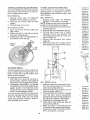
LUBRICATION
r quitar el freno
larcha adelante
_ovimiento. M&s
:s la velocidado
SAE:VtSCOSITY
c ._'_
,
0
'-_
30
-_i_
3Z
&O
_
"i'r_MPERA'T.URE RAI_GE AHTICIPATED
eQ
80
lee
1_ ......
_!.............
_
4.
BF.,FOR_ NEXT OIL CHANGE
NOTE: Although multi*viscosity oils (5W30,
10W30 etc.) improve starting in cold weather,
they will result in increased oil consumption
when used above 32°R Check your engine
oii level more frequently to avoid possible
engine damage from running low on oil.
Change the oil after' every 25 hours of operation or at least once a year if the tractor is
not used for 25 hours in one year,
Check the
the engine
operation.
each time
crankcase oil level before starting
and after each eight (8) hours of
Tighten oil fill cap/dipstick securely
you check the oil level,
TO CHANGE
ENGINE
OIL
Determine
temperature
range expected
before oil change. All oil must meet API
service classification
SG - SL,
• Be sure tractor is on level surface.
• Oil wilt drain more freely when warm.
, Catch oil in a suitable container.
1. Remove oil fill cap/dipstick.
Be careful
not to allow dirt to enter the engine when
changing oil.
2. Removeyell0wcapfrom
end ofdrain valve
and install the drain tube onto the fitting.
COOLING
The transmission fan and cooling fins should
be kept clean to ensure proper cooling.
Do not attempt to clean fan or transmission
while engine is running or while the transmission is hot. To prevent possible damage
to seals, do not use high pressure water or
steam to clean transaxfe.
- Inspect cooling fan to be sure fan blades
are intact and clean.
• Inspect coelingfins fordirt, grass clippings
and other materials. To prevent damage to
seals, do not use compressed
air or high
pressure sprayer to clean cooling fins°
TRANSAXLE
GRADES
-r
........... _0
V - BELTS
Check V - belts for deterioration
and wear
after 100 hours of operation and replace if
necessary. The belts are not adjustable. Replace belts if they begin to slip from wear,
TRANSAXLE
HACIAATRh, S
¢imientos est&n
tarcha adelante
Only use high quality detergent oil rated with
API service classification SG-SL Select the
oil's SAE viscosity grade according to your
expected operating temperature.
roll Drain Valve
PUMP FLUID
The transaxle was sealed at the factory and
fluid maintenance is not required for the life of
the transaxie. Should the transaxle ever leak
or require servicing, contact your nearest
Sears or other qualified service center.
Drain
Tube
21
MUFFLER
Unlock drain valve by pushing inward
slightly and turning counterclockwise.
4. To open, pull out on the drain valve.
5_ After oil has drained completely, close and
lock the drain valve by pushing inward
and turning clockwise until the pin is in
the locked position as shown.
6_
Remove the drain tube and replace the
cap onto the end of the drain valve.
7. Refill engine with oilthrough oil fill dipstick
tube° Pour slowly, Do not overfill. For
approximate
capacity see "PRODUCT
S PECIF1CATIONS"section
ofthis manual.
Use gauge on oil fill cap/dipstick
for
checking
level. For accurate
reading,
insert dipstick into the tube and push
down firmly into place before removing.
Keep oil up to, but not over, the "FULL:.'
line on dipstick. Push dipstick down firmly
into the tube when finished.
3_
ENGINE
Inspect and replace corroded muffler and
spark arrester (if equipped) as it could create
a fire hazard and/or damage.
SPARK PLUG(S)
Replace spark plug (s) atthe beginning of each
mowing season or after every 100 hours of
operation, whichever occurs first Spark plug
type and gap setting are shown in "PROD UCT
SPECIFICATIONS"
section of this manual
FAMILIARtC
LEA ESTE f_tb
SU TRACTOF
Compare 1as
controtes y ajt
IN - LINE FUEl.. FILTER
The fuel filter should be replaced once each
season. If fuel filter becomes clogged, obstructing fuel flow to carburetor, replacement
is required.
1. With engine cool, remove filter and plug
fuel line sections.
2. Place newfuel filter in position in fuel line
with arrow pointing towards carburetor.
3o Be sure there are no fuel line leaks and
clamps are properly positioned.
4. Immediatelywipe
up any spilled gasoline.
OIL, FILTER
®
Replace the engine oil filter every season or
every other oil change if the tractor is used
more than 100 hours in one year,
AIR FILTER
Your engine will not run properly using a dirty
air filter. Service air cleaner more often under
dusty conditions_ See Engine Manual.
CLEAN
CLEANING
• Clean engine, battery, seat, finish, etc. of
all foreign matter,
• Keep finished surfaces and wheels free
of all gasoline, oil, etc.
• Protect painted surfaces with automotive
type wax.
We do not recommend using a garden hose
or pressure washer to clean your tractor
unless the engine and transmission
are
covered to keep water out. Water in engine
or transmission wilt shorten the useful life of
your tractor. Use compressed
air or a leaf
blower to remove grass, leaves and trash
from tractor and mower.
AIR SCREEN
Air screen must be kept free of dirt and chaff
to prevent engine damage from overheating. Clean with a wire brush or compressed
air to remove dirt and stubborn dried gum
fibers.
ENGINE
COOLING
SYSTEM
Debris may clog the engine's air cooling
system_ Remove blower housing and clean
area shown to prevent overheating
and
engine damage.
Air Scree
n"---._._
Clean out chaff
and debris
(A) PALANCA
CESORiO - S_
el conjunto s
montados en',
(B) PEDAL DE
y frenar el trac
(C) PALANC
NAMIENTO posici6n del fr
(D) CONTROl.
controtar ]a ve
(E) PALANC/
SORIO - Se t
segadoras, o
en su tractor
22
n elproducto,
WARNING: OR
SERVICE
TOADJUSTMENTS:
AVOID SERIOUS
1.
2.
3.
4.
5.
6.
INTERRUPTOR
DE IGNICI6N
EDAL DE FRENO!
DEEMBRAGUE
NO PONGA EN
MARCHA SIN EL
CONTENEDOR,
BEFORE
PERFORMING
ANY
Depress brake pedal fully and set parking brake.
Place motion control lever in neutral position.
Place attachment clutch in "DISENGAGED"
position.
Turn ignition key to "STOP" and remove key.
Make sure the blades and aI! moving parts have completely stopped.
Disconnect spark plug wire from spark plug and place wire where it cannot
come in contact with plug.
TO REMOVE
LEVANTAMIENTO
DE LA SEGADORA
INJURY,
MOWER
8.{ Slide mower out from under right side of
tractor.'
IMPORTANT: If an attachment otherthan the
mower is to be mounted on the tractor, removethe front link (E) and rear lift liks (C) from
tractor and hook the clutch spring (Q) into
the cable guide on front edge of lower dash.
t.
Place attachment
clutch in "DISENGAGED" position.
2. Lower attachment lift lever to its lowest
position°
3. Roll belt off engine pulley (M) and belt
keepers (G).
4. Remove cable (P) by depressing tab (L).
5, Remove clutch cable spring (Q) from
idler arm (R)o
6, Disconnect front link (E) from mowerremove retainer spring and washer.
7. Go to either side of mower and disconnect mower suspension
arm (A) from
chassis pin (B) and rear lift link (C) from
rear mower bracket (D) - remove retainer
springs and washers.
CAUTION: After rear lift links are disconnected, the attachment lift lever will be spring
loaded. Have a tight grip on lift lever when
changing position of the lever.
TO INSTALL
MOWER
Be sure tractor is on level surface and engage
parking brake,
:
I. Lower attachment lift lever to its lowest
position.
CAUTION:
Lift lever is spring loaded,
Have a tight grip on lift lever, lower it slowly
and engage in lowest position.
NOTE: Be sure mower side suspension
arms (A) are pointing forward before sliding
mower under tractor.
2, Slide mower under tractor until it is cen-,
tered under tractor.
se evita,
, si no se evita,
]raves.
si no se evita,
noderadas.
:I simbolo
;de
_or.
i peligro que,
erte, lesiones
evita, puede
ylo danos
23
3. A'I-FACH MOWER
SIDE SUSPENSION
7.
ARMS (A) TO CHASSIS - Position hole
in arm over pin (B) on outside of tractor
chassis and secure with retainer spring,
4. Repeat on opposite side of tractor,,
8_ Hook end of clutch cable spring (Q) into
hole in idler arm (R).
9, Push clutch cable housing guide (P) into
bracket,
10, Install belt onto engine pulley (M) and belt
keepers (G).
ATTACH REAR LIFT LINKS (C) - Lift
rear corner of mower and position slot
in link assembly
over pin (D) on rear
mower bracket and secure with washer
5,
and retainer
Insert end of link (E) into hole in front
mower bracket
(H) and secure with
washer and retainer spring (J) o
spring°
REVISION
LLANTAS
Las ]lantas e
masiado en la
presi6n de la_
para obtener
• Reduzca la
que se indk
REVISION
CON JUNTO
Para obtener I
la caja de la
en la forma
LA CAJA DE
Servicio y Aju!
REVISION U
DE TODAS
Vea las figura
correas de im
dora y de mov
Ajustes de estl
sJgan su paso
REVISION
.
IMPORTANT:
Check belt for proper
in all mower pulley grooves_
11.Raise
attachment
lift lever to
position,
12, If necessary, adjust gauge wheels
operating mower as shown in the
tion section of this manual_
ATTACH FRONT LINK (E) - Work from
left side of tractor, Insert rod end of link
assembly
through front hole in tractor
front suspension
bracket (F)..
24
routing
highest
before
Opera-
E
Una vez que u
tractor, verifiql
mente. Ver "F
BIEN EL FRE
ajustes de est
•
i; ii
;OIVlPLETO
_cisodetenerel
enodeestacioIaensacadora
)e identifique
la
la ensacador&
_.>,-
TO LEVEL MOWER
Make sure tires are properly inflated to the
PSI shown on tires° If tires are over or under
inflated, it may affect the appearance ofyour
lawn and lead you to think the mower is not
adjusted properly.
VISUAL
SIDE-TO-SIDE
i>
i
FRONT-TO-BACK
_ i!
!
IMPOR'fANT:
ADJUSTMENT
!ii
Deck must be level side - to
_', I
i_
-sid6
'I ! _ej!'
TO obtain the
t cutting results, the mower
blades should 15Qadjusted so the front tip is
1/8" t0 3/8" lower than the rear tip when the
._ower is' in its highest position,.
CAUTION:
Blades are sharp° Protect
your hands with i gloves and/or wrap blade
with heavy cloth!
* Raise mower to highest position.
. Position any blade so the tip is pointing
straight forwar&
Measure distance
(B)
.to the ground at front and rear tip of the
blade,
' _
, If front tip of blade is not 1/8" to 3f8" lower
than the rear tip, go to the front of tractor.
, With an 1t/16"
or adjustable
wrench,
loosen jam nut A several turns to clear
adjustment nut B.
ADJUSTMENT
1. With all tires properly inflated and if your
Fawn appears unevenly cut, determine
which side of mower is cutting lower.
2o With a 3/4" or adjustable wrench, turn lift
link adjustment nut (A) to the left to lower
LH side of mower, or, to the right to raise
LH side of mowen
NOTE: Each full turn of adjustment nut wilt
change mower height about 3/16".
ensacadora (3),
1superior y.gireale en pomc_on,
!
,ndo trabaje en
_uede utilizar
Turn nut righ
to raise mower
° With a 3/4" or adjustable wrench, turn
Turn nut left
to lower mower
front link adjustment
nut (B) clockwise
(tighten) to raise the front of mower, or,
counterclockwise
(loosen) to lower the
front mower.,
la
", "2"0 "3" ("3"
"nenos tupido).
_leta de la ensare) orienlado hacuentra situado.
azo (3) de manarte inferior del
lora (3) pase por
ta, y asegSrese
! compteto (3) y
los orificios de
; la ensacadora
ra apretarlo (8)_
e afiojar las su_rla paleta (5) y
3,
Test your adjustment
by mowing some
uncut grass and visually checking the
appearance.
Readjust, if necessary, until
you are satisfied with the results.
PRECISION
SIDE-TO-SIDE
ADJUSTMENT
1. With atltires properly inflated, parktractor
on level ground or driveway°
_1_ CAUTION:
Blades are sharp. Protect
your hands with gloves and/or wrap blade
with heavy cloth.
2. Raise mower to its highest position.
3. At both sides of mower, position blade at
side and measure the distance (A) from
bottom edge of blade to the ground. The
distance should be the same on both sides.
4. If adjustment
is necessary, see step 2 in
Visual Adjustment
instructions above.
5o Recheck measurements,
adjustifnecessary until both sides are equal,
Tighten adjust nut
B to raise mower
!
: f
Loosen adjust
nut B to lower
mower
! ' Loosen jam nLit Afirst
NOTE: Each full turn of the adjustment nut
wilt change mower height about I/8"o
, Recheck measurements,
adjust if necessary until front tip of blade is 1/8" to 3/8"
lower than the rear tip,
• Hold adjustment nut in positionwithwrench
and tighten jam nut securely against adjustment nut,
IA
25
TO REPLACE
MOWER BLADE DRIVE BELT
TO REPLACE
The mower blade drive belt may be replaced
without tools. Park the tractor on level surface° Engage
parking
brake.
BELT
•
•
BELT REMOVAL-
1, Remove
mowero(See
"TO REMOVE
....MOWER" in this section of manual.)
2. Work belt off mandrel pulley and idler
pulleys.
3o Pull belt away from mower,
BELT INSTALLATION
DRIVE
Park the tractor on level surface. Engage
parking brake, For assistance,
there is a
belt installation guide decal on bottom side
of left footrest.
BELT REMOVAL-
..............
MOTION
1o Remove
mower (See "TO REMOVE
MOWER" in this section of manual).
NOTE: Observe entire motion drive belt and
position of all belt guides and keepers°
2. Remove beltfrom stationary idler (A) and
clutching idler (B)_
3/ Remove belt from centerspan idler (C).
6. Pull belt slack toward rear of tractor.
Carefully
remove
belt upwards
from
transmission
input pulley and over cooling fan blades (D).
4. Remove
belt downward
from engine
pulley (E),
5. Slide belt toward rear of tractor, off the
steering plate (F) and remove from tractor.
-
Work belt around mandrel pulley and
idler pulleys
2. Make sure belt is in all pulley grooves
and inside all belt guides.
3. Install mower (See "To Install Mower" in
this section of this manual).
1,
Mandrel
•
Insertedos
ranuras cu
tapa de fa
cuadradas
a cada lad_
•
Vuelque la
cios del b_
y asegt_re:
soldada de
en el sopoi
del asa (9)
Introduzca
1/4(1 l)enll
das (t0) y
Cotoque (
orificios de
soldada de
•
•
TO CHECK
Co!oque la
(con la cuL
Deslice la
sacadora (
tapao Asec
de la parte
ensacador
de la pieza
deben desl
BRAKE
If tractor requires more than five (5) feet to
stop at highest speed in highest gear on a
level, dry concrete or paved surface, then
brake must be sen;iced.
You may also check brake by:
I. Park tractor on a level, dry concrete or
paved surface, depress brake pedal all
the way down and engage parking brake.
2. Disengage
transmission
by placing
freewheel control in "transmission disengaged" position, Pull freewheel
control
out and into the slot and release so it is
held in the disengaged position.
The rear wheels must lock and skid when
you try to manually push the tractor fopJvar&
If the rear wheels rotate, then the brake
needs to be serviced, Contact a Sears or
other qualified service center.
BELT INSTALLATION
-
1, Install new belt from tractor rear to front,
over the steering plate (F) and above
clutch brake pedal shaft (G).
2, Pull belt toward front of tractor and roll
belt onto engine pulley (E),
3, Pull belt toward rear of tractor, Carefully
work belt down around transmission
4.
5,
6.
7.
26
cooling fan and onto the input pulley (D).
Be sure belt is inside the belt keeper,
Install belt on centerspan idler (C).
Install belt through stationary
idler (A)
and clutching idler (B).
Make sure belt is in all pulley grooves
and inside all belt guides and keepers.
Install mower (See"TO INSTALL MOWER" in this section of manual).
"
Gire el lad,
•
Cotoque c
de 1/4 (13
frontal de
contratuen
Introduzca
a trav6s dc
detantera
•
•
Encaje la
(14) en la I:
anterior de
•
Deslicelat
adas en 1o
tubos del b
DOR
TO REMOVE
a sin el captador
lsitivos de segu,s condiciones.
1.
2.
)r superior de la
(2) situada en la
nsacadora (deje
r los extremos),,
ficios del lade
Jperior soldada
)s orificios cor_
astidor superior
aredondade 1/4
)rcas de 1/4 (6).,
izq - uierdo de la
e la ensacadora
dientes de! tubo
_nsacadora (1).,
aredondade 1/4
.=rcasde 1/4 (6)°
WHEEL
FOR REPAIRS
Block up axle securely.
Remove axle cover, retaining ring and
washers to allow wheel removal (rear
wheels have a square key - Do not lose).
3o Repair tire and reassemble.
NOTE: On rear wheels only: align grooves in
rear wheel hub and axle. insert square key.
4. Replace washers and snap retaining ring
securely in axle groove.
5_ Replace axle cover,.
NOTE: To seal tire punctures and prevent
flat tires due to slow leaks, purchase and
use tire sealant from Sears° Tire sealant also
prevents tire dry rot and corrosion.
Weak or _
Dead
Battery
2.
Charged
BaLtery
from the fully charged battery.
RED cable last from both batteries_
REPLACING
BATTERY
n_asWARNING: _Do not short battery termiby allowing awrench or any other object
to contact both terminals at the same time.
Before connecting
battery, remove metal
bracelets, wrist*watch bands, rings, etc.
Positive terminal must be connected first to
prevent sparking from accidental grounding.
1o Lift seat pan to raised position.
2o Disconnect
BLACK battery cable first
then RED battery cable and carefully
remove battery from tractor.
3. Install new battery with terminals in same
position as old battery°
4. First connect RED battery cable to positive (+) terminal with hex bolt and keps
nut as shown. Tighten securely, Slide
terminal cover over terminal
5. Connect
BLACK grounding
cable to
negative (-) terminal with remaining hex
bolt and keps nut. Tighten securely_
Ring,
_-
FRONT WHEEL TOE - IN/CAMBER
"four new tractor front wheel toe - in and
camber is set at the factory and is normal. The
frontwheel toe -in and camber are not adjustableo If damage has occurred to affect the
factory set front wheeltoe -in or camber, contact a Sears or other qualified service center.
TO START ENGIN EWITH WEAK BATTERY
_,WARNING:
Lead-acid batteries generate
explosive gases. Keep sparks, flame and
smokingmaterialsawayfrom
batteries.Always
wear eye protection when around batteries.
Seat
If your battery istoo weakto startthe engine, it
should be recharged. (See "BATTERY" in the
MAINTENANCE
section of this manual).
.'abeza redonda
_n los lados del
adora, y apriete
!_1
TO REMOVE CABLES, REVERSE ORDER 1. BLACK cable first from chassis and then
Washers
Square
Key _
(Rear W,
iheel Only)
E_]l
3. Connect the other end of the BLACK
cable (D) to good chassis ground, away
from fuel tank and battery.
Retaining
Axle
[[_]
Fully
If "jumper cables" are used for emergency
starting, follow this procedure:
IMPORTANT: Your tractor is equipped with a
12 volt system. The other vehicle must also
be a 12 volt system.. Do not use your tractor
battery to start other vehicles.
Terminal
Nut
Negative
TO ATTACH JUMPER CABLES ' ............... Cover ,.....
"................ /
b
_lacK)
1. Connect one end of the RED ca le
_..._
_Cable...
".(_.
to the POSITIVE
(+) terminal of each
'
_
_
--_
battery(AB), taking care not to short
Positiv
against tractor chassis.
(Red)
2o Connect one end of the BLACK cable
Cable
to the NEGATIVE (-) terminal (C) of fully
charged battery.
27
Bolt
TO REPLACE
HEADLIGHT
BULB
1_ Raise hoo&
2. Remove bulb hotderfrom the hole in the
backside of the grill
3. Replace bulb in holder and install bulb
holder securely back into the hole in the
backside of the grill ......
4. Close hood.
TRANSMISSION
INTERLOCKS
ENGINE
FUSE
TO ADJUST
4,
TO ADJUST
CONTROL
CHOKE
CONTROL
The choke control
has been preset at
the factory and adjustment
should not be
necessary. If adjustment
is necessary, see
engine manual_
REMOVE HOOD & GRILLASSEMBLY
Raise hood.
Unsnap headlight wire connector.,
Stand in front of tractor, Grasp hood at
sides, tilt toward engine and lift off of
tractor,
When replacing hood, be sure to reconnect the headlight wire connector.
I
THROTTLE
The throttle control has been preset at
the factory and adjustment
should not be
•necessary
Check adjustment
as described
below before loosening cable, tf adjustment
is necessary, see engine manual.
Replace with 20 amp automotive
- type
plug - in fuse_ The fuse holder is located
behind the dash_
TO
1.
2..
3.
EP LACEM ENT
Should your transmission require removal for
service or replacement,
it should be purged
after reinstallation and before operating the
tractor. See "PURGE TRANSMISSION"
in
the Operation section of this manual.
AND RELAYS
Loose or damaged wiring may cause your
tractor to run poorly, stop running, or prevent
it from starting.
• Check wiring, See the electrical wiring
diagram in the Repair Parts manual
TO REPLACE
R E MOVAL/R
TO ADJUST
CARBURETOR
You r carburetor has bee n preset at the factory
and adjustment
should not be necessary.
However, minor adjustment may be required
to compensate for differences in fuel, temperature, altitude or load. If the engine does
need adjustment, see engine manual.
Headlight
Wire
Connector
\
Su tractor nue_
tado por razon
las partes y los
herramientas c
HERRAMIE
El. f,/IONTAJ
Un juego de tL
A continuaci6r
llaves est&nda
(t) Llave de 51
(2) Llaves de,
(2) Llaves de
(1) Llave de 9t
Cuando en est
nos "mane der
a cuando ustec
eraci6n (sentac
PARA REMt
CAJA DE CJ
DESEMPAQU
•
Remueva
accesibles
de cart6n !
•
Cortaralo L
los cuatro [
neles de ci,
•
Revise si
cart6n y re
ANTES DE I
LA CORRE[
VERIFIQUE L
1. Levante t_
levantada.
AViSO: Si est_
mes y aSo indi
que se encuen
bateria por un
Base de
Asienlo
ADJUNTE
EL
MONTAJE DE!
SORIO DE TF
1.. Deslice el
volante inf
2. Ponga las
de la dire_
orejas, en
para asegl
INSTALACIOI,
3,, Ponga tas
que est_n
28
t
ill
u
i6n
Immediately prepare your tractor for storage
at the end of the season or if the tractor will
-
Empty the fuel tank by starting the engine
and letting it run until the fuel lines and
carburetor are empty.
• Never use engine or carburetor
cleaner
products in the fuel tank or permanent
damage may occur,,
. Use fresh fuel next season,
NOTE: Fuel stabilizer
is an acceptable
alternative
in minimizing
the formation
of
fuel gum deposits
during storage.
Add
stabilizer to gasoline in fuel tank or storage
container. Always follow the mix ratio found
on stabilizer container, Run engine at least
10 minutes after adding stabilizer to allow
the stabilizer to reach the carburetor. Do not
not be used for 30 days or more.
_WARNING:
Never store the tractor
with
gasoline in the tank inside a building where
fumes may reach an open flame or spark,
Allow the engine to cool before storing in
any enclosure,
TRACTOR
_lante
lirecci6n
_=sonode
;ci6n de la
"ecci6n
When tractor is to be stored for a period
of time, clean it thoroughly, remove all dirt,
grease, leaves, etc. Store in a clean, dry area.
1. Clean entire tractor (See"CLEANING"
in
the Maintenance section of this manual),
2. Inspectand replacebelts,ifnecessary
(See
belt replacement instructions in the Service
and Adjustments section of this manual)°
3. Lubricate as shown in the Maintenance
section of this manual,
4. Be sure that all nuts, bolts and screws
are securely fastened.
Inspect moving
parts for damage, breakage and wear.
Replace if necessary..
5, Touch up all rusted or chipped paint
surfaces; sand lightly before painting.
empty the gas tank and carburetor
fuel stabilizer.
ENGINE OIL
Drain oil (with engine warm) and replace
with clean engine oil. (See "ENGINE" in the
Maintenance
section of this manual).
CYLINDER(S)
I. Remove spark plug(s).
2. Pourone ounce ofoifthrough
spark plug
hole(s) into cylinder(s).
3, Turn ignition key to start position for a
few seconds to distribute oil.
BATTERY
le
}n
J
randela
:guridad
4.
. Fully charge the bat[ery for storage.
. After a period of time in storage, battery
may require recharging.
" To help prevent corrosion and power leakage during long periods of storage, battery
cables should be disconnected
and battery cleaned thoroughly (see "TO CLEAN
BATTERY
AND TERMINALS"
in the
Replace
with new spark plug(s).
OTHER
• Do not store gasoline
another°
from one season to
• Replace your gasoline can if your can
starts to rust. Rust and/or dirt in your
gasoline wilt cause problems.
• If possible, store your tractor indoors and
cover it to give protection fro m dust and dirL
• Cover your tractor with a suitable protective cover that does not retain moisture.
Do not use plastic. Plastic cannot breathe
which allows condensation
to form and
will cause your tractor to rust.
IMPORTANT:
Never cover tractor while
engine and exhaust areas are still warm.
Maintenance
section of this manual),
. Aftercleaning,
leavecablesdisconnected
and place cables where they cannot come
in contact with battery terminals.
• If battery is removed from tractor for
storage, do not store battery directly on
concrete or damp surfaces.
ENGINE
FUEL SYSTEM
pendiente
if using
IMPORTANT:
it is important to prevent gum
deposits from forming in essential fuel system parts such as carburetor, fuel hose, or
tank during storage° Also, alcohol blended
fuels (called gasohol or using ethanol or
methanol) can attract moisture which leads
to separation and formation of acids during
storage. Acidic gas can damage the fue!
system of an engine while in storage.
29
TROUBLESHOOTING
CHART:
See appropriate section in manual unless directed to Sears service center
PROBLEM
Will not start
Hard to start
Engine will not
turn over
CAUSE
CORRECTION
1
Out of fuel,
2
Engine not "CHOKED"
3
ESPECIFIC_
Capacidad y"
de gasoline:
Tipo de Aceit_
(APt _ SG - Sl
Fill fuel tank_
See "TO START ENGINE" in
Operation section,
Capacidad dE
Aceite:
Engine flooded.,
Wait several minutes before
attempting to start,
Bujia:
4
Bad spark plug.
Replace spark plug,
S
Dirty air filter.
Cleanfreplace
6
Dirty fuel filter-
Replace fuel fitten
7
Water in fuel,
Empty fuel tank and carburetor,
refill tank with fresh gasoline and
replace fuel filter,,
8
Loose or damaged wiring_
Check all wiring°
9
Carburetor' out of adjustmer
See "To Adjust Carburetor" in
Service and Adjustments section,
10
Engine valves out of adjustment.
Contact a Sears or other qualified
service center.,
1
Dirty air filter,,
Cleanlreplace
2
Bad spark plug.,
Replace spark plug.
3
Weak or dead battery,
Recharge or replace battery.
4
Dirty fuel filter.
Replace fuel filter,
5
Stale or dirty fuel.
Empty fuel tank and refill tank with
fresh, clean gasoline,
6
Loose or damaged wiring,
Check all wiring,
7
Carburetor
See "To Adjust Carburetor" in
Service and Adjustments section,
8
Engine valves out of adjustment.
Contact a Sears or other qualified
service center.
Brake pedal not depressed.
Depress brake pedal,
Attachment
Disengage attachment
prop
out of adjustmer
clutch is engaged.
Vetocidad de
Recorrido (Mt
Sistema de C
air filter.
Bateria:
air filter.,
clutch°
Weak or dead battery.
Recharge or replace battery,
Blown fuse.
Replace fuse
Corroded battery terminals,
Clean battery terminals_
Loose or damaged wiring,
Check all wiring,
Faulty ignition switch_
Check!replace
ignition switch_
Faulty solenoid or starter°
Check/replace
solenoid or stadero
Faulty operator presence
switch(es) o
Contact a Sears or other qualified
service center,
3O
Torsi6n del PE
de la Cuchilla
FELICITACIOI
sido diseSado,
mejor confiabili
En el caso de
problema que
haga el favor
centro de serv
servicio cualifb
bien capacitac
ramientas ade
reparar este tn
Haga el favor
Estas instruc
mantener su ur
observe las "R
RESPONSA
• Leay obser
• Siga un pro!
cuidado y u_
• Siga las ins
clones "Mal
de este Mar
_DVERTEr
con un motor d
user sobre, o cl
cubierto de bo
o menos que
venga equipad
que cumpla co
existen)o Si se
et operador de
trabajo eficienl
En el estado dc
(Secci6n 4442
Code"). Otros
leyes parecida
en la tierras fec
cercano tiene c
pas para el sile
de Repuesto e
TROUBLESHOOTING
See appropriate
d sonafiladas.
;uantesy porter
e hacenoperaIfrenofrecuent3peraciones
de
_anecesario.
asdeseguridad
esario°
t_libredeo!ras
marcha_
parala
I b,rea_
CHART:
section
PROBLEM
in manual
unlessdirected
Loss of power
_,mirar adelante
3equeSos
: una pendiente
ntal.
_,archa baja de
_rarseo cambiar
_ren una pendi:ci6n,desconeclespacio cuesta
_tras va cuesta
_illas, porter la
Jespacio_
_S si no es neoy gradualmente
vibration
Engine continues
to run when oper
- ator leaves seat
with attachment
clutch engaged
t
to. Sears service
center
CORRECTION
CAUSE
Engine clicks but
will not start
Excessive
_
Weak or dead battery,
1
Recharge
or replace battery.
2
Corroded battery terminals,
Clean batter'] terminals.
3
Loose or damaged wiring,,
Check att wiring.
4
Faulty solenoid or starter.
Check/replace
1
Cutting too much grass/too
2
Throttle in "CHOKE" position.
Adjust throttle control
3
Build - up of grass, leaves and
trash under mower.
C]dan underside of mower
housing,
4
Dirty air filter.
Clean!replace
5
Low oil level/dirty oil.
Check oil level/change
6
Faulty spark plug.,
Clean and regap ol change spark
plug.
7
Dirty fuel filter,
RePlace fuel filter,
8
Stale or dirty fuel
Empty fuel tank and refill tank with
fresh, clean gasoline.
9
Water in fuel,,
Empty fuel tank and carburetor,
refill tank with fresh gasoline and
replace fuel filter.
10
Spark plug wire loose.
Connect/tighten
11
Dirty engine air screentfins_
12
Dirty/clogged
:
i'
Clean engine air screen/fins.
{
Clean!replace muffler.
13
Loose or damaged wiring,
;
Check all wiring,
14
Carburetor
15
Engine valves out of adjustment.
Contact a Sears or other qualified
service center.
1
Worn, bent or loose blade,
Replace blade_ Tighten blade bolt
2
Bent blade mandrel.
Contact a Sears or other qualified
service center_
3
Loosetdamaged part(s),
Tighten loose part(s), Replace
damaged parts.
1
Faulty operator - safety presence
control system.
:
Check wiring, switches and
connections, if not corrected,
contact a Sears or other qualified
service center,
muffler,
fast,
out of adjustment.
31
solenoid or starter,,
Ra!se cutting height!reduce
speed.
air filter.
oil.
spark plug wire.
See "To Adjust Carburetor" in
Service and Adjustments section.
TROUBLESHOOTING
See appropriate
CHART:
section
in manual
unless
directed
to Sears service
center
•
PROBLEM
CAUSE
Poor cut - uneven
cutting
Worn, bent or loose blade_
1
Replace blade, Tighten blade boll
Mower deck not level.
2
Level mower decks
Buildup of grass, leaves, and
trash under mower,
3
Clean underside of mower
housing.
Bent blade mandrel.
4
Contact a Sears or other qualified
service center,
Clogged mower deck vent from
build * up of grass, leaves, and
trash around mandrels.
5
Clean around mandrels to
open vent holes.
Obstruction
1
Remove obstruction,
2
Replace mower drive belt,
Frozen idler pulley,
3
Replace idler pulley,
Frozen blade mandrel
4
Contact a Sears or other qualified
service center,
.
•
Mower blade will
not rotate
CORRECTION
in clutch mechanism_
mower drive belt,.
Engine speed too slow,
1
Place throttle control in "FAST"
position,
Travel speed too fast,
2
Shift to slower speed.
Wet grass.
3
Allow grass to dry before mowing
Mower deck not level
4
Level mower deck,
Low/uneven
5
Check tires for proper PSI,,
Worn, bent or loose blade,
6
Replace blade. Tighten blade bolt,,
Buildup of grass, leaves and
trash under mowe_
7
Clean underside of mower
housing_
Mower drive belt worn°
8
Replace mower drive belt.
Blade improperly installed,,
9
Reinstall blade sharp edge down,
Improper blade used,
I0
Replace mower blade°
tire air pressure°
Clogged mower deck vent holes 11
from buildup of grass, leaves, and
trash around mandrelsr
Clean around mandreis to
open vent holes.
w
Headlight(s)
not
working
(if so equipped)
•
.
Worn/damaged
Poor grass
discharge
•
Light switch is "OFF".
1
Turn light switch "ON"o
Bulb(s) or lamp(s) burned out.
2
Replace bulb(s) or lamp(s).
Faul[y light switch,
3
Check/replace
Loose or damaged wiring.
4
Check wiring and connections.
Blown fuse.
5
Replace fuse°
light switch.,
Escoger un
modo que n,
estando en
No cortar la I
perder tracc
Porter siem
en pendient
cuesta abajc
Evitar arran
ente. Si lasr
tar las cuch
abajo en la!
Mantener
tc
dientes lent
repentinos
{
pueden cau
Ponerlam&
funciona
cc
dispositivos
estabilidad
entes empir
Nointentart
pie en el ter
No cortarce
Las m&quin;
si una rued_
m.NitrOS
Si el operador
de los niSos pt
Los niSos a me
na y las activi
de que los hi5
5ltima vez que
• Mantener Io
vigilados pol
el operador.,
• Estar alerta
entra en el
• Antes y dura
y abajo par_
• Nunca Ileval
apagadas.
F
o interferir c
mb,quinao Io
edentement
&rea de cort,
o tumbados
• Nunca dej_
m_.quina_
o Tener el m_
a cantos ci
objetos que
IV, REMOLQ
.
32
Remolcar s(
gancho dise
equipo o rer
al efecto_
TROUBLESHOOTING
CHART:
See appropriate
section
in manual
tes y de lanzar
ieden producir
sin el captador
sitivos de segucondiciones.
:endida sin vigi.
chillas, poner el
_rar el motor, y
,radores a partir
los por un gran
a la conducci6n
tdores tendrian
hacer funcionar
,astante seguro
otras personas
de[ fabricante
de las ruedas,
e hierba, hojas
reden tocar el
motor calientes
.=el puente del
otros residuos
cioneso Limpiar
arburante antes
; la m&quina o
,s de guardarla,.
_ENDIENTES
factor de acci,ontrol y vuelco,
ridas o muerte.
,_srequiere una
._hacer marcha
;ntes incomodo,
directed
I
to Sears
service
center
CORRECTION
1
Bad battery cell(s).
1
Replace battery,
2
Poor cable connections.
2
Check/clean all connections.
3
Faulty regulator (if so equipped)°
3
Replace regulator
4
Faulty alternator
4
Replace alternator,
I
Freewheel control in "disengaged" 1 Place freewheel control in
position,,
"engaged" position.
2
Motion drive belt worn, damaged, 2
or broken.
3
Air trapped in transmissionduring 3
sh pment or serv cing.
j
:
Engine "backfires"
when turning
engine "OFF"
I
Engine throttle control not set 1 Move throttle control between
between half and full speed (fast)
half and full speed (fast) position
position before stopping engine°
before stopping engine_
Engine dies when
tractor is shifted
into reverse
1
Reverse operation system (ROS) 1 Turn ignition key to ROS "ON"
is not "ON" while mower or other
position, See Operation section,
attachment is engaged. ; =::
Battery
charge
Loss
will not
of drive
Replace motion drive bett.
;
se opera cerca
rgar o descargar
cami6n,.
;ci6n cuando se
CAUSE
_ROBLEM
7do no se corta_
todas los panes
antes de limpiar
3r de hierba, o
_scargao
go con la luz del
la estando bajo
I
unless
Mower will not
operate
•t
Bagger or optional rear discharge 1
deflector is not installed correctly
NEED MORE HZLP?
You'l.I find the
answer
and more
Purge transmission..
Check bagger or optional rear
discharge deflector for proper
installation
I
i
i :):
ii
on managemyhome.com
• Find this and at[ your other product manuals on[ineo
• Get answers from our team of home experts°
I
o, for f_ee!
:
Ii:•!
ii,
• Get a personalized maintenance plan for your home,
• Find information
manage
and toots to help with home projects.
home
b[ought, to you by Seats
!;=
una pendiente,
;, las raices, los
,tos escondidos_
car la m&quina.
r obst&culos.
33
Garantia ...........
Reglas de Sec
Especificacion
Montaje/Pre 0
Operaci6n ......
Mantenimientc
Z
O
u
I==
t
/
ILl
I:L
/
DOS A_OS
/
O
I
LU
U=
/
(I)
re
1
/
O
1
1
W
GARANTJA
Si opera y ma
debido a defec
compra, comu
Durante et pri_
servicio de ga_
disponible lue,(
Si usted tran_
cancelar_.n. P_
z
O
90 DJAS PAl
Si la bateria qL
(nuestras prue
la fecha de co_
0
CO
EslEagarantia ,_
• Los artioLd,
bujias, liml
• EIservicio
• El reempla
exteriores
• El reempla
y mantanir
• Las repara
daSos cau
pacto de o
• Las repar_
daSos el_c
utilizaci6n
inflamable
se encuen
•
La limpiez_
erado conl
dias a part
•
EIdeterion
Si alguna vez
garantia del tr_
Esta garantia
Unidos.
Esta garantia i
que varian de
Sears,
34
Roeb
Garantia
.....................................................................
35 Programa
de Mantenimiento
............................
53
ReglasdeSeguridad
...............................................
36 Servicioy Ajustes.................................................
57
.......................................................
63
Especificaciones
delProducto
................................
39 Almacenamiento
deProblemas
.........................................
64
MontajeiPre
Operaci6n
.....................................
4! ldentificaci6n
Operaci6n
...................................................................
46 Ser'¢icio
Sears......................................
Contratapa
Mantenimiento
......................................................
53
GARANTiA
LIMITADA
DE CRAFTSMAN
DOS AI_IOS PARA TRACTORES
Si opera y mantiene este tractor seg_]n todas las instrucciones provistas, y este deja de funcionar
debido a defectos del material o de la mano de obra dentro de los dos aSos posteriores a la fecha de
compra, comuniquese al 1-800-4-MY-HOME® para ob[ener una reparaci6n sin cargo.
Durante el primer aSo a partir de la fecha de compra, no incurrir,'_ en gastos ocasionados por et
servicio de garantia a domicilio.. Para su conveniencia, el servicio de garanfia a domicilio aQn estar&
disponibte tuego del primer aSo a partir de la fecha de compra, pero se apficar&n gastos de traslado..
Si usted transporta el tractor a un lugar de entrega autorizado de Craftsman, estos gastos se
cancelar&n. Para Iocatizar el lugar autorizado mb,s cercano, comuniquese al 1-800-4-MY-HOME®.
90 DiAS PARA BATERiAS
Si la bateria que se incluye con este tractor resulta defectuosa en los materiales o en la mano de obra
(nuestras pruebas demuestran que no mantiene la carga) dentro de los 90 (noventa) dias a partir de
la fecha de compra, ser& reemplazada a domicilio sin cargo,
Esta garantia SOLO cubre los defectos en los materiales yen la mano de obrao Sears NO pagar& por:
•
•
•
•
•
•
,
•
Los articutos prescindibles que se desgastan con e! uso normal, que incluyen, entre otros: hoias,
bujias, limpiadores de aire, correas y filtros de aire.
El servicio de mantenimiento est&ndar, cambios de aceite o puestas a punto.
El reemplazo ni la reparaci6n de neum,_ticos debido a las pinchaduras provocadas por objetos
exteriores como clavos, espinas, tocones o vidrios.
El reemplazo ni ta reparaciSn de neum&ticos o ruedas debido al uso normal, accidente u operaciSn
y mantenimiento incorrectos.
Las reparaciones necesarias debido al abuso por parte del operador, que incluyen, entre otros:
daSos causados por el remolque de objetos que sobrepasen la capacidad del tractor, por el impacto de objetos que doblen ]a estructura o el cigLieSal, o por el exceso de velocidad del motor.
Las reparaciones necesarias debido a la neg]igencia del operador, que incluyen, entre otros:
daSos el#ctricos o causados por el medio ambiente debido al almacenamiento inapropiado, la no
utifizaci6n de ta cantidad ni el grado adecuado de aceite para el motor, ia acumulaci6n de basura
inflamabfe en ta plataforma, o la falta de mantenimiento del equipo segOn las instrucciones que
se encuentran en el manual del operador.
La limpieza del motor (sistema de combustible) ni las reparaciones debido a combustible considerado contaminado u oxidado (viejo).. En general, el combustible debe usarse dentro de los 30
d[as a partir de la fecha de compra.
El deterioro y uso normal de los acabados exteriores ni el reemplazo de ta etiqueta del producto..
Si alguna vez, este tractor se utiliza con fines comerciates o de alquiler, toda la cobertura de fa
garantia del tractor y de la bateria serb, nulao
Esta garantia se aplica t)nicamente
Unidos.
mientras el producto permanezca
dentro de los Estados
Esta garantia le otorga derechos legales especificos yes posible que usted goce de otros derechos
que varian de estado en estado°
Sears,
Roebuck
and Co,, Hoffman
Estates,
35
IL 60179
TROUBLE_
See approl
_PELIGRO:EstaMaquina
cortadora es capaz de amputar las manosy los pies y de lanzar
objetos° si no se observan las instrucciones de seguridad siguientes se pueden producir
lesiones graves o la muerteo
_ADVERTENClA:
Siempre desconecte el
alambre de la bujfa y p6ngalo donde no pueda
entrar en contacto con la bujia, para evitar el
arranque per accidente, durante la preparaci6n,
el transporte, el ajuste o cuando se hacen
reparaciones.
,_ADVERTENCIA:
No avance cuesta abajo
a punto muerto ya que podria perder el control
del tractor.
_ADVERTENCIA:
Remolque solamente los
accesorios recomendados y conformes alas
caracteristicas indicadas per el fabricante de su
tractor_ Tenga cuidado y prudencia al utilizar el
tractorr Cuando se encuentre en un declive, oper
utilizando exclusivamente la velocidad m_,sbaja,
En case de un dective una carga excesiva podria
resultar peligrosa. Los neum_,ticos pueden perder
la tracci6n con el suelo y hacerle perder el control
de su tractor.
_a_DVERTENClA:
El tube de escape det motor,
algunos de sus constituyentes y algunos componentes del vehiculo contienen o desprenden
productos qulmicos conocidos en el Estado de
California come causa de c&ncer y defectos al
nacimiento u otros daflos reproductivos.
_j:_DVERTENCIA:
Los bornes, terminales y accesorios relatives de ia bateria contienen plomo
o compuestos de plomo, productos quimicos
conocidos en el Estado de California come causa
de c&ncer y defectos al nacimiento u otros dafles
reproductivos. Lavar las manes despu6s de
manipularlos.
t. FUNCIONAMIENTO
GENERAl.
• Leer, entender y seguir todas las instrucciones
sobre la m&quina yen el manual antes de
empezar,
• No poner las manes o los pies cerca de partes
giratorias o debajo de ta m&quina, mantener
siempre limpia la abertura de descarg&
• Permitir el funcionamiento de la m&quina sS!o a
adultos que tengan familiaridad con las instrucclones.
• Limpiar el #,rea de objetos come piedras,
juguetes, cables, etc° que pueden ser recogidos y disparados con las cuchitlas
• Asegurarse de que el &rea est6 libre de otras
personas antes de ponerla en marcha. Parar
la m&quina si alguien entra en el &tea..
• Nunca Ilevar pasajeros_
• No cortar marcha atr&s a! no ser absolutamente
necesario. Mirar siempre aba]o y deiante mientras se procede atr&s,
• Nunca dirigir el material descargado hacia
nadie., Evitar descargar material contra paredes
u obstrucciones,. El material podr[a rebotar
hacia el operador. Parar las cuchiilas cuando
se pasan superficies de grava,,
36
• NO hacer funcionar la m&quina sin el captador
de hierba entera u otros dispositivos de seguridad en su lugar yen buenas condiciones
• Ralentizar antes de girar,
• Nunca dejar una m&quina encendida sin vigilancia, Apagar siempre las cuchillas, poner el
freno de estacionamiento, parar el motor, y
quitar ias liaves antes de baiar.
Desconectar las cuchillas cuando no se coda.
Apagar el motor y esperar que todas las partes
est6n completamente paradas antes de timpiar
la m&quina, quitar ei captador de hierba, o
desatascar ta protecci6n de descarga,,
, Hacer funcionar la m&quina s61ocon la luz del
dia o tuz artificial buena°
. No hacer funcionar la m&quina estando bajo
los efectos de alcohol o droga.
. Poner atenci6n al tr&fico cuando se opera cerca
de calles o se cruzan,.
Poner la m_ima atenci6n al cargar o descargar
la m&quina en una caravana o cami6n,.
. Llevar siempre galas de protecci6n cuando se
hace funcionar la m&quina.
* Los dabs indican que los operadores a partir
de los 60 aSos est&n afectados per un gran
porcentaje de heridas relativas a la conducci6n
del cortac6spedo Estos operadores tendrian
que evaluar su habilidad de hacer funcionar
el cortac#sped de mode 1o bastante seguro
para proteger a si mismos y a otras personas
de heridas graves.
" Seguir las recomendaciones del fabricante
para los pesos y contrapesos de las ruedas.
. Mantener la m&quina libre de hierba, hojas
u otros escombros
que pueden tocar el
tube de escape / partes del motor calientes
y quemarseo No permitir que el puente del
cortac_sped cargue hojas u otros residues
que pueden causar acumutacioneso Limpiar
toda salpicadura de aceite o carburante antes
de hacer operaciones sobre la mAquina o
guardarla_ Dejarla enfriar antes de guardarla.
II. FUNClONAIVlIENTO
EN PENDIENTES
Las pendientes son el mayor factor de accidentes relatives a la p6rdida de control y vuelco,
que pueden causar severas heridas o muerte,.
El funcionamiento en pendientes requiere una
atenci6n extra. Si no es posible hacer marcha
atr&s en una pendiente o site sientes incomodo,
no la cortes.
• Cortar hacia arriba y abajo de una pendiente,
no de mode horizontal..
, Poner atenciones a los hoyos, las raices, los
bulbs, las piedras u otros objetos escondidos.
El terreno irregular puede volcar ia m&quinao
La hierba alta puede esconder obst&culos_
PROBLEM
Battery
charge
will
Loss of drb
Engine "ba
when turni_
engine "OF
Engine die.,
tractor is sl
into reversq
Mower will
operate
• Find this
, Get answ
, Get a per
, Find info
n3an
;vice
center
ghten blade bolt,
)f mower
_r other qualified
_drels to
Dn.,
rive bell
)Y
,r other qualified
[rol in "FAST"
=.ed.
"before mowing
)per PSI,
ghten blade boll
}f mower
rive belt,.
arp edge down,
lade.
ldrels to
9H".
r lamp(s)..
it switch,,
connections.,
• Seguir las recomendaciones del productor con
respecto a los limites del equipo por remolcar
y el remolque en pendientes.
• Nunca permitir que ni[_os u otras personas
est6n dentro del equipo por remolcar,
• En pendientes, el peso del equipo remolcado
puede causar la p_rdida de tracci6n y ta p6rdida de control.,
• Viajar despacio y dejar m&s distancia para
frenar,,
V. SERVIClO
MANIPULACION SEGURA DE LA GASOLINA
Para evitar heridas personates o daBos alas
cosas, porter el m_tximo cuidado a la hora de manipular la gasolina. La gasolina es extremamente
inflamable y los vapores son explosivos,
• Apagar todos los cigarrillos, cigarros, pipas y
otras fuentes de ignici6n,.
• Usar s6to contenedores para gasolina aprobados,,
• Nunca quitar el tap6n de la gasolina o aSadir
carburante con el motor en marcha, dejar
enfriar el motor antes .dei abastecimiento de
la gasolina.
• Nunca abaslecer la m&quina at interior de un
local.
• Nunca guardar,la m_,quina o el contenedor
del carburante donde haya una llama abierta,
chispas o una luz piloto corno un calentador
de agua u otros dispositivos_
• Nunca Ilenar los contenedores ai interior de
un vehiculo o en una caravana o cami6n
recubiertos con un forro de pl_stico. Colocar
siempre los contenedores en el terreno lejos
del vehiculo cuando se est_ tlenando
• Quilar el equipo de gas del cami6n o caravana
y abastecerlo en el terrenoo Si no es posibte,
abastecer dicho equipo con un contenedor
port&ill, mb,s bien que de un surtidor de gasolina_
o Mantener la boqui!la a contacto del borde
del dep6sito de carburante o la abertura del
contenedor durante toda la operaciSn de
abastecimiento, No utilizar un dispositivo con
boquilla cerrada - abierta.
• Si se vierte carburante sobre la ropa, cambiarse la ropa inmediatamente,
• Nunca Ilenar el dep6sito mb,s de Io debido,
Votver a colocar el tap6n del gas y cerrar de
modo firme,
• Escoger una vefocidad de marcha baja de
modo que no sea necesario pararse o cambiar
estando en una pendiente,,
• No cortar la hierba mojada,, Las ruedas pueden
perder tracci6n.
Poner siempre una marcha cuando se est&
en pendientes, No porter en punto muerto e ir
cuesta abajo,
° Evitar arrancar, pararse o girar en una pendiente. Si las ruedas pierden tracci6n, desconectar las cuchilfas y proceder despacio cuesta
abajo en la pendiente.
• Mantener todo los movimientos en las pendientes lentos y gradual, No hacer cambios
repentinos de velocidad o direcci6n, ya que
pueden causar el escape de la m&quinao
• Poner la m,_.ximaatenci6n cuando la m&quina
funciona con captadores de hierba u otros
dispositivos enganchados; pueden afectar la
estabilidad de la m&quina. No usar en pendientes empinados,
. No intentar estabilizar fa m&quina poniendo el
pie an el terreno_
• No cortar cerca de bajadas, cunetas y orillas,,
Las m&quina puede volcarse improvisamente
si una rueda est& en el borde o se hunde.
II!. NItrOS
Si el operador no pone atenci6n a la presencia
de los niBos pueden ocurrir accidentes tr_gicos.
Los niSos a menudo est&n atraidos pot ta m&quinay las actividad de cortar. No dar por hecho
de que los niSos se queden adonde estaban la
51tima vez que los vistes.
• Mantener los ni_os fuera del &tea de corte y
vigilados pot un adulto responsable que no sea
el operador,
• Estar alerta y apagar la m&quina si un niSos
entra en el &rea.
• Antes y durante la marcha atr_,s, mirar adelante
y abajo para ver si hay ni_os pequeSoso
• Nunca Ilevar niSos, incluso si hay las cuchillas
apagadas., Podrian caer y herirse seriamente
o interferir con el funcionamiento seguro de la
m&quina los ni[ios que se han Ilevado precedenternente pueden aparecer de pronto en el
&tea de corte por otro paseo y set atropetlados
o tumbados pot la m_.quinao
o Nunca dejar que los niSos manipulen la
m&quina.
• Tener el m&ximo cuidado cuando se acerca
a cantos ciegos, arbustos, &rboles u otros
objetos que pueden impedir la vista de niifos.
IV. REMOLQUE
• Remofcar s61o con una m_.quina que tenga un
gancho diseSado para remofcar. Enganchar el
equipo o remolcar s61o en el punto dispuesto
at efecto.,
OPERACIONES DE SERVtClO GENERALES
• Nunca hacerfuncionar la m_quina en un _.rea
cerrada,
. Mantener todas las tuercas y pernos apretados
para asegurarse de que trabaja en condiciones
seguras,
• Nunca modificar los dispositivos de seguridad,
Controlar su correcto funcionamiento regularmente.
37
TROUBLE, €
See appro!
• Mantenerlamb,quinalibrede hierba,hojas
u otros residuesacumulados.Limpiar]as
salpicaduras de aceite o carburante y quitar
cualquier cosa mojada con carburanteo Dejar
que la m&quina se enfrie antes de guardaria_
• Si se golpea un objeto ajeno, hay que pararse
e inspeccionar la mAquina. Reparar, si es necesario, antes de volver a poner en marcha.
• Nunca hacer ning_n ajuste o reparaciSn con
el motor en funciSn.
• Controlar los componentes del captador de
hierba y la protecciSn de la descarga frecuentemente y sustituir con partes recomendadas
per el fabricante, en su case.
• No cortar marcha atr&s al no ser absolutamente
necesarioo Mirar siempre abajo y delante mientras se precede atr&s.
• Nunca llevar niSos, incluso si hay las cuchillas
apagadaso Podrian caer y herirse seriamente
o interferir con el funcionamiento seguro de la
mAquina° los niAos que se han llevado precedentemente pueden aparecer de pronto en el
&rea de corte per otro paseo y ser atropellados
o tumbados per la m&quina.
. Mantener los niSos fuera del &rea de corte y
vigilados per un adulto responsable que no sea
el operador.
• Estar alerta y apagar la m_quina si un niSos
entra en el #.tea.
• Las cuchillas del cortac_sped son afiladas,
Envolver la cuchilla, ponerse guantes y poner
fa m&xima atenci6n cuando se hacen operaclones en e!laso
• Controlar el funcienamiento del freno frecuentemente. Ajustar y hacer las operaciones de
mantenimiento cuando eso sea necesario.
• Mantener y sustituir las etiquetas de seguridad
e instrucci6n, cuando sea necesario,.
• Asegurarse de que et _rea est_ libre de otras
- personas antes de ponerla en marcha, para la
m&quina si alguien entra en el &rea.
• Nunca Ilevar pasajeros..
. Antes y durante ta marcha atr&s, mirar adelante
y abajo para vet si hay ni#,os pequeSos.
• Cortar hacia arriba y abajo de una pendiente
(I5 ° Mb.x), no de mode horizontal.
• Escoger una velocidad de rnarcha baja de
mode que no sea necesario pararse o cambiar
estando en una pendiente.
• Evitar arrancar, pararse o girar en una pendiente. Si las ruedas pierden tracci6n, desconectar las cuchillas y preceder despacio cuesta
abajo en la pendiente,
• Si la m&quina se para mientras va cuesta
arriba, desconectar las cuchi!fas, poner ta
marcha atr&s y ir hacia atr&s despacio.
• No girar estando en pendientes si no es necesario, y luego girar despacio y gradualmente
cuesta abajo, si es posible.
Engine clic
will not stal
Loss
of po\
Excessive
Engine con
to run whel
- ator leave
with attachl
clutch eng_
3B
/
ESPECIFICACIONES
rvice center
DEL PRODUCTO
Capacidad y Tipo
de gasotina:
1.5 Gatones (5,68 L)
Regular Sin Ptomo
Tipo de Aceite:
(API- SG- SL)
SAE 30 (Sobre 32°F/0°C)
SAE 5W30
(Debajo 320F/0°C)
:NGINE" in
Capacidad de
Aceite:
Con filtro: 56 oz,
Sin filtro: 48 oz.,
tes before
BujJa:
Champion RC12YC
(Abertura: °030")
Delante:
0 - 5.5
Velocidad de
go
filter°
'
AmpiHr:
Min_ CCA:
Case Size:
• Ser_,icio experto de nuestros 12.000 especialistas profesionales en la reparaci6n,,
28
230
Ut R
• Servicio ilimitado sin cargo alguno para
las partes y la mano de obra sobre todas las
reparaciones garantizadas.
Torsi6n del Perno
de la Cuchilla:
45 - 55 Ft. Lbs.
Lrburetor" in
;tments section°
r other qualified
filter°
Lcebattery_
ld refill tank wit]
ine,
rburetoP in
Itments section.
.r other qualified
dai,
merit clutch.
_ce batteryo
linats
_ition switch°
enoid or starter,
_rother qualified
Sustituci6n del producto si su producto
garantizado no puede set arreglado..
FELICITACIONES por la compra de su tractor. Ha
sido diseflado, planificado y fabricado para darle ia
mejor confiabitidad y el mejor rendimiento posible_
En el caso de que se encuentre con cualquier
problema qua no pueda solucionar f_cilmente,
haga el favor de ponerse en contacto con un
centro de servicio Sears o con un otto centro de
servicio cuatificado, Cuenta con representantes
bien capacitados y competentes y con los herramientas adecuadas para darle servicio o para
reparar este tractor,
Haga el favor de leer y de guardar este manual,
Estas instruc - clones fe permitir&n montar y
mantener su unidad en forma adecuada. Siempre
observe las "REGLAS DE SEGURIDAD."
RESPONSABILIDADES
Descuento dei 10% sobre el precio corriente
del servicio y de los partes relativas al servicio
no cubiertas pot el acuerdo; tambi_n et 10%
menos sobre el precio corriente de un control
de mantenimiento preventivo.
Ayuda r_pida por tel6fono - soporte telef6nico por parte de un representante Sears sobre
productos qua requieren un arreg]o en casa, y
adem&s una programaci6n sobre fos arregtos
m&s convenientes.
Cuando se ha comprado el Acuerdo, basta con
una ltamada telef6nica para programar el servicio.
Puede Ilamar cuando quiera, dia y noche o fijar
en linea una cita para obtener el servicioo Sears
tiene m&s de 12o000 especialistas profesionales
en la reparaci6n, que tienen acceso a mb,s de 4°5
miltones de partes y accesorios de catidad.
DEL CLIENTE
• Lea y observe las reglas de seguridad.
• Siga un programa regular de mantenimiento,
cuidado y uso de su tractor,
• Siga las instrucciones descritas en las sec_
clones "Mantenimiento" y 'Rlmacenamiento"
de este Manual del DueSoo
_ADVERTENClA:
Este tractor viene equipado
con un motor de combusti6n interna y no se debe
usar sobre, o cerca, de un terreno no desarrotlado
cubierto de bosques, de arbustos o de c6sped,
o menos que el sistema de escape del motor
venga equipado con un amortiguador de chispas
que cumpla con los leyes locales o estatales (si
existen). Si se usa un amortiguador de chispas,
el operador debe mantenerlo en condiciones de
trabajo eficientes.
En e] estado de California, la tey exige Io anterior
(Secci6n 4442 de! "California Public Resources
Code") Otros estados pueden contar con otras
leyes parecidas. Las leyes federales se aplican
en ta tierras federales.. Su centro de Servicio m_s
cercano tiene disponible amortiguadores de chispas para el silenciador. (Vea la secci6n de Partes
de Repuesto en et manual lngf_s del dueSo.)
t
la Reparaci6n y Prot_gese de molestias y gastos
inesperados,. _ !/'
Un Acuerdo inclu_/e los puntos siguientes:
Recorrido (MPH): Marcha Atr&s:
0 - 2.4
Sistema de Carga: 3 Amps Bateria
5 Amps Luces Delanteras
Bateria:
td carburetor,
,h gasoline and
ACUERDOS
DE PROTECCI0N
PARA
LA REPARACION
Congratulacione,_ por su buena compr& Su
nuevo productd ,Craftsman_J est#, diseSado y
fabricado para funcionar de modo liable pot
muchos a6oso Pero como todos los productos,
puede necesitar i&lguna reparaci6n de tanto en
tanto. En este caso tener un Acuerdo de Protecci6n para la Rep'a_raci6npuede hacerles ahorrar
dinero y fastidiosJ
Compre ahora u_ Acuerdo de Protecci6n para
Este es el tipo de profesionalidad con que puede
contar para ayudar a alargar la vida dot producto que acaba de comprar, por muchos ar_os.
iCompre hoy su Acuerdo de Protecci6n para ta
Reparaci6n!
Se aplican algu'nas limitaciones
y exclusiones, Para conocer los precios y tener m&s
lnformaci6n, Ilame al 1 - 800 - 827. 6655,
SERVlCIO
DE INSTALAClON
SEARS
Para la instatacidn profesionat Sears de aparatos de casa, puertas de garaje, calentadores de
agua y otros importantes articulos para la casa,
en U.S.A Ilamar a
I _ 800 - 4 - MY -HOME@ ............................
39
i
•
Volante
Contenedor
de direcci6n
Immediately
at the end of
not be used
_WARNIN(
gasoline in t]
fumes may r
Allow the en
any enclosur
©
TRACTOR
(8) 1!f_ X 20 ;<,! _25'I.........
(6)_.1/_x 20 x I, 15
Perno cabeza redondo
Perno hexagonal
(I O) 1/4 x 20
Tuerca de reborde
lnserto del
volante de
direcci6n
Volante
de direcci6n
(5) 1/4x 20
Tuerca cuadrado
Adaptador
Accesorio de
transci6n de la
dJrecci6n
(1) Perno
(Rosca pot pl_.stico)
(2) 1/4 x 15 x 0.5"
Tornilla (Oro)
(Rosca por pl_.stico)
Eje de
Extenci6n
(1) Arand_ela
(1) Arandela
de retenci6n
secul
parts for
Replace i
Touch ut:
surfaces;
BATTERY
(3) I/4 x 20 x 0.75" Perno
Abrazadera
are
5,
CC
(2) 1/4 x 1,15"
Bosscrew
When tracto
of time, cleaE
grease, leave
1. Cleanent
the Maint,
2. Inspectan
beltreplac
andAdjus
3, Lubricate
section o:
4. Be sure t
de seguridad
Pasador
. Fully chart
. After a pet
may requi_
• To help pre
age during
cables she
ten! cleane
BATTERY
Maintenan
. After clean
and place
in contact
• If battery
storage, d_
concrete o
ENGINE
Asiento
(1) Tubo de
desag_e
llll
(I) Arandela
(1) Asiento
(2) Llaves
(1) Perno
40
Hoja
de pendiente
FUEL SYSTI
IMPORTAN1
deposits fron
tem parts su,
tank during
fuels (called
methanol) ca
to separation
storage, Ack
system of an
ire removal for
uld be purged
operating the
}MISSION"
in
manual,
)NTROL
,en preset at
_hould not be
as described
If adjustment
tual,
ROL
en preset at
_hould not be
ecessary,
see
_tatthe factory
)e necessary.
ay be required
s in fuel, teme engine does
manual.
Su tractor nuevo ha side montado en la f&brica con la excepci6n de aquellas partes que no se han morn
tado per razones de envio. Para asegurarse que su tractor funcione en fornqa adecuada y segura todas
las partes y los articulos de ferreterfa que se monten tienen que ser apretados en forma segura° Use las
herramientas correctas, seg_n sea necesario, para asegurarse de que est_n apretados en forma segura.
HERRAMIENTAS
NECESARIAS
PARA
EL MONTAJE
Un juego de llaves de tube facilitar& et montaje.
A continuaci6n se enumeran los tamaSos de las
Ilaves est_ndar.
(1) Llave de 5/16"
Cuchillo
(2) Llaves de 7/I6"
Medidor de presi6n
(2) Ltaves de 1/2"
Pinzas
(1) Llave de 9/!6"
4,
Remueva el adaptador def volante y deslice
el adaptador sobre la extensi6n del eje de
direcci6no i
5, Ponga el volante de direcci6n de rnanera que
las barras transversales queden horizontaies
(izquierda a derecha) y desl[eelo al interior del
eje y sobre el adaptadoro
6. Monte la arandela plana grande, arandela
de seguridad 5/16, perno hexagonal 5/16 en
forma segura,,
7, Presione el inserto del volante de direcci6n
en el centre de 6ste.
8. Remueva el embalage de cart6n del cap6 y
de la rejitla'.
IMPORTANTE: Revise y remueva todas las
grampas en la corredera porque puden perforar
las llantas en donde el tractor tiene que rodar
para salirse de ella,
;t
Cuando en este manual se mencionan los t_rminos "mane derecha" o "mane izquierda" se refiere
a cuando usted se encuentra en la posici6n de operaci6n (sentado/a detr#.sdel volante de direcci6n).
PARA REMOVER
EL TRACTOR
DE IA
CAJA DE CARTON
DESEMPAQUE LA CAJA DE CARTON
•
Remueva todas las pantes sueltas que est_n
accesibles, y ias cajas de partes, de la caja
de cart6n grande.
• Cortar a to largo de las lineas de puntos en todos
los cuatro paneles de cart6n. Remover los paneles de cierre y aplanar los paneles laterales_
•
Revise si hay partes sueltas adicionales o
cart6n y remu_valas.
ANTES DE REMOVER EL TRACTOR
DE
LA CORREDERA
VERIFIQUE LA BATERIA
Arandela de
Pemo _I_!_
t' Seguddad
_Arandela
PranaGrande
Volante de
Direcci6n
1.
Levante la base del asiento a la posiciOn
levantada
AVISO: Siesta bateria esta utilizada despu6s del
mes y aSo indicado sobre la etiqueta (ta etiqueta
que se encuentra entre los terminales), cargue fa
bateria per un minimo de una hera a 6 - 10 amps.
Base del
Asiento
INSTALACION DEL ASIENTO
Ajuste el asiento antes de apretar el perno de ajuste,,
Io Remueva la pemo y ta arandela plana que
aseguran el asiento al empaque de cart6n y
p6ngalos de lade para poder ulilizarlos durante
la instalaci6n del asiento sobre el tractor. Remueva y desechese del embaFaje de cart6no
2, Conecte el interrupter con el asiento,
3. Colocar el asiento yen el asiento del recipiente
de manera que latres (3) c0jins est_ posicionada
en el agujero ancho ranurado en el recipiente.
4. Empujar en el asiento para enganchar e!
cojins en la ranura y empujar et asiento hacia
la parte trasera del tractor,.
5,, Levante el asiento y apriete la perno de ajuste
en forma segura,
6. Remueva y desechese del cinla,
ADJUNTE EL VOLANTE DE DIRECCION
Me NTAJE DELEJE DE EXTENSION Y ELACCE_SORIO DE TRANSICION DE LA DIRECCION
I.
Deslice el eje de extensiSn sobre et eje del
volante inferior.
2o Ponga las orejas del accesorio de transici6n
de la direcci6n sobre las ranuras para las
orejas, en el tablero, y empujelas hacia abajo
para asegurarlas,
tNSTALACION DELVOLANTE DE DIRECCION
3,
Ponga las ruedas delanteras deI tractor para
que est6n indicadas hacia adelante,,
41
PARA
MONTAR
EL CONTENEDOR
No hacer funcionar la mfiquina sin et captador
de hierba entera u otros dispositivos de seguridad en su lugar yen buenas condiciones.
lntroduzca el tubo del bastidor superior de la
ensacadora (I) porta argolla (2) situada en la
parle superior det tejido de la ensacadora (deje
floja la parte de la argolla por los extremos),
TO REMOVI
I.
2.
Block up
Remove
washers
wheels h_
3. Repair tit
NOTE: On re
rear wheel h_
4,
Replace_
securely
5, Replace;
NOTE: To sc
flat tires due
use tire seata
Cinta
,>
Arn6s de
alambrado
.......... 7:Baje
el asiento a la l_0sici6n de operaci6n
y si_ntese en el asientoo Presione el pedal
del freno completamente haste abajo. Si la
posici6n de operaci6n no est& c6moda, ajuste
el asientoo
PARA AJUSTAR EL ASIENTO
Agarre el mango de ajuste y fev&ntese, deslice el
asiento ala posici6n deseada y suelte el mango
de ajuste,
Ranurado
Cinta
prevents
.
•
Primero alinee los dos orificios del lado
derecho de la estructura superior soldada
de la ensacadora (4) con los orificios correspondientes del tubo del bastidor superior
de la ensacadora (1).
Coloque dos tornillos de cabeza redonda de I/4
x 1,25 (5) y fijelos con dos tuercas de 1/4 (6),,
tire
Retaining
Axle
Ring\
Cover,
Square_
(Rear Wheel
FRONT
•
Perno
LengCieta
Mango de
ajuste
•
AVtSO: Ahora puede rodar su tractor fuera de la
corredera, Siga las siguientes instrucciones pare
remover e! tractor de la corredera,,
ADVERTENClA: Antes de empezar, leer, entender y seguir todas las instrucciones presentes
en la secci6n Operaciones de este manual.
Asegurarse que el tractor est6 en un &rea bien
ventilada. Asegurarse que la zone delante del
tractor este libre de otras personas y objetos.
PARA HACER RODAR EL TRACTOR FUERA
DE LA CORREDERA (VEA LA SECCiON DE
LA OPERACI6N PARA LA LOCALIDAD Y LA
FUNCI(DN DE LOS CONTROLES)
•
°
.
•
Alinee los dos orificios del lado izq - uierdo de ]a
estructura superior soldada de la ensacadora
(4) con los orificios correspondientes del tubo
del bastidor superior de la ensacadora (t),
Coloque dos tornitlos de cabeza redondade I/4
x 1,25 (5) y fijelos con dos tuercas de 1/4 (6),,
WHI
Your new tr_
camber is set
front wheel to
able. If dam_
factory set frc
tact a Sears c
TOSTARTEI
_WARNIN!
explosive ga
smokingmate
wear eye pro
tfyourbattery
should be rec
MAINTENAb
lnstale otros dos tornillos de cabeza redonda
(7) hacia la parte posterior, en los lados del
bastidor superior de la ensacadora, y apriete
las contratuercas a mano (8).
Levante la palanca de levantamiento del accesorio a su posici6n m&s alta.
Suelte el freno de estacionamiento presionando e! pedal del freno.
Ponga el control de la rueda libre en ]a
posici6n de giro libre pare desenganchar la
transmisi6n. (Vea "PARA TRANSPORTAR"
en la secci6n de Operaci6n de este manual).
Haga rodar et tractor hacia delante fuera de
la correderao
tf "jumper ca
starting, folio
IMPORTAN']
12 volt systei
be a 12 volt
battery to st_
TO ATTACH
1. Connect
to the P(
battery(A
against tr
2,, Connect
to the NE
charged
•
Remueva las bandas que sujetan la protecci6n contra la descarga en contra del tractor°
Continuer con las siguientes instrucciones.
42
t
LVEBELT
_face.Engage
3e, there is a
_nbottomside
FO REMOVE
ff manual),
drivebeltand
i keepers_
ryidler(A)and
_panidler (C).
.=ar of tractor,
•
•
•
•
Jpwards from
and over cootfrom
engine
•
tractor, off the
vefromtractor,
•
Coloque ta tapa de la ensacadora del rev_s
(con la cubierta protectora inlacta),
Destice la pieza de uni6n del asa de la ensacadora (9) en el hueco det interior de la
tapa., Aseg_rese de que las dos lengL_etas
de la parte superior encajan en la tapa de la
ensacadora, Los dientes de la parle inferior
de la pieza de uni6n del asa de la ensacadora
deben deslizarse entre los dientes de ta tap&
Inserte dos tuercas cuadradas (10) en las dos
ranuras cuadradas de la parte anterior de la
tapa de la ensacadora, y otras dos tuercas
cuadradas en las dos ranuras cuadradas (una
a cada lado) de la parle posterior de la tapa_
Vuelque la ensacadora (3), alinee los orificios del bastidor con los orificios de la tapa
y asegL_rese de que la estructura superior
soldada del bastidor se encuentra colocada
en el soporte de pl&stico de la pieza de uni6n
del asa (9),
introduzca cuatro pasadores hexagonales de
1/4 (1I) en losorificios concuatro tuercas cuadradas (I0) y apri6telos basra que queden fijos.
Coloque dos torniltos de 1/4 (12) en los
orificios del centro de la estructura superior
soldada det bastidoro
•
Introduzca dos pasadores hexagonales de
1/4 (16) a trav6s de los orificios de la parte
superior del bastidor frontal de la ensacadora
y enr6squelos en las tuercas del interior de
los tubos del bastidor,.
•
In'troduzca una pinza de plb.stico (17) hacia
abaje pot la argolla del tejillo en el lado
derecho y ajOstela en el bastidor frontal (14) a
101 mm (4 pulgadas) de la parte superior del
lubo del bastidor frontal de la ensacadora,
,
Desinstale las contratuercas (21) de ia parte
posterior det bastidor superior y de la parle
inferior del bastidor frontal de la ensacadora
y fije riostras (22) a cada lado,
Vuelva a colocar y apretar las contratuercas
(21) hasta que queden completamente fiiaso
if
@
1
t
I
I
|
1
|
I
|
•
Destice la junta de goma (23) hasta la parte superior del asa met&lica de la ensacadora (24),
•
Deslice el asa de la ensacadora (24) hacia
abajo por la tapa y los orificios de la estructura
superior soldada,
lntroduzca el pasador de horquilla (25) a
trav6s de! orificio de la parte inferior del asa
de la ensacadora y deslice la arandela de
retenci6n (26) en el orificio det pasador hasta
quede encajada,,
_J
•
_r rear to front,
F) and above
•
Gire et lado derecho hacia arriba,,
G).
•
Coloque dos tornil!os de cabeza redonda
de 1/4 (13) en la parte inferior del bastidor
frontal de la ensacadora (I4) y apriete las
contratuercas a mano (15)_
...............
Introduzca elbastidorfrontal (14) hacia arriba
a trav_s de las argollas del tejilto de la parte
delantera de la ensacadora.
ractor and roll
i),
ctor. Carefully
transmission
put pulley (D)..
belt keeper,
idler (C)o
,nary idler (A)
,ulley grooves
and keepers.
STALL MOWlual) o
•
•
Encaje la parle inferior' del bastidor frontal
(14) en la pieza de piastico situada en fa parte
anterior del fondo de la ensacadora.
..........
•
Deslice la parle de las argollas det tejido, situadas en los extremos de ia belsa, sobre los
tubos del bastidor superior de ta ensacadora,
43
PARA INSTALAR EL BRAZO COMPLETO
CON PALETA
•
Antes de la instalaci6n es preciso detener el
motor de! tractor y porter el freno de estacionamiento.
• Sitt]ese detrfis del tractor con la ensacadora
........ fuera de fa placa de apoyo (1) e identifique la
zona de contacto total (2) de la ensacadora..
• Coloque
lacubiedatrasera
decierre(27)defoF
maqueencaieenlosbordesdesujeciSn
(28).
A]ineelosorificiosde[ deflectorde hierba
(29)conlasprotuberancias
de latapadela
ensacadora,.
• Enprimerlugar,instaleunpasador
hexagonal
de1/4(30)enel lateral,comose indica,.
, A continuaci6n,
coloqueotro pasadorhexagonaldeI/4 (31)enlapartesuperior,
TO LEVEL
Make sure til
PSI shown ol
inflated, it ma
lawn and lea
adjusted pro!
VISUAL S1D:
1 ,, With all tit
lawn app
which sid
2o With a3/z
link adjus
LH side o
LH side c
NOTE: Each
change mow
Tome el brazo completo de ta ensacadora (3),
inserte la brida (4) en la ranura supedor y girela hasta que el brazo (3) encaje en posici6n.
_';/::!:
Frontal De Tractor
PARAMONTARLOSCOMIPONENTES
DEL
CONTENEDOR
AL TRACTOR
::::::/:i
ii i¸:: :: L_'"
_i_
ii::/ _:_
:
®
•
• Antesde la instalaci6nes precisodetener
el motordel tractory porterel freno de
estacionamiento.
• Instalemuellesdecierre(!) en tos orificios
.
No instale la paleta (5) cuando trabaje en
hierba hfimeda muy tupida.
Con c6sped menos denso puede utilizar la
paleta (5) con los ajustes "t", "2"o :'3" ("3"
sirve para el c6sped seco o menes tupido),.
Etija el ajuste y haga girar la paleta de la ensacadora (5) con el nfimero (ajuste) orientado hacia ia posici6n en la que se encuentra situado,
de montaje de la placa de apoyo..
•
•
lnserte un pasador hexagonal (2) por el
orificio de cada muelle y et orificio correspom
diente de la placa de apoyo,
Fije la contratuerca (3) al pasador de cada
lado de la placa de apoyo.
"
•
,
44
Coloque la paleta (5) en el brazo (3) de manera que fa brida (6) de la parte inferior del
brazo eompleto de la ensacadora (3) pase per
Ia ranura rectangular correcta, y asegfirese
de que los orificios del brazo completo (3) y
ta paleta (5) est_n atineados.
Introduzca un tornillo (7) per los orificios de
ta paleta (5) y el brazo (3) de la ensacadora
y utilice una contratuerca para apretarlo (8)°
Para cambiar et ajuste puede aflojar las sujeciones (7 y 8), quitar o girar la paleta (5) y
apretarlas de nuevo.
to raise mowe
0294
3., Test your
uncut grE
appearar
you are s
PRECISION
1, With alltir
on level c
A_, CAUTIO]
your hands \
with heavy c
2. Raise mc
3, At both si.
side and
bottom e(
distances
4, if adjustrr
Visual Ac
5. Recheck
sary until
, hole in front
secure with
g (4.
_pring (Q)into
REVISION
DE LA PRESION
DE LAS
LLANTAS
Las llantas en su unidad fueron infladas demasiado en la f&brica por razones de envio_ La
presi6n de fas l]antas correctas es importante
para obtener el mejor rendimiento en el corte.
• Reduzca la presi6n de los neum&ticos a ]a PSI
que se indica en estos.
REVISION
DE LA NIVELACiON
DEL
CON JUNTO
Para obtener los mejores resuItados en et corte,
la caja de la segadora tiene que estar nlvelada
en la forma adecuada. Vea "PARA NIVELAR
LA CAJA DE LA SEGADORP;' en la secci6n de
Servicio y Ajustes de este manual
guide (P)into
REVISION DE LA POSIClON
DE TODAS LAS CORREAS
.=y(M) and belt
Vea las figuras que aparecen para cambiar las
correas de impulsiSn de la cuchilla de la segadora y de mowmiento en la secci6n de Servicio y
Ajustes de este manual. Verifique que Ins correas
sigan su paso correcto_
REVISION
3roper routing
LISTA DE REVISION
Antes de operar y de disfrutar de su tractor nuevo,
le deseamos que reciba el mejor rendimiento y la
mayor satisfaccion de este producto de catidad.
Haga el favor de revisar la lista a continuacion:
vf Se han completado todas tas instrucciones de
montaje,
vf No quedan partes sueltas en la caja de cartSno
vz La bateria est& preparada y cargada en forma
adecuadao
vf El asiento ha sido ajustado en forma c6moda
y apretado en forma segura.
V" Todas las Ilantas hart sido infladas en forma
adecuada,i (Para fines de envio, las Ilantas se
inflaron demasiado en ta f&brica.)
Vf AsegL_rese que el conjunto segador est#
nivelado en forma adecuada, de lado a lado
y desde adelante hacia atr_.s, para obtener los
mejores resultados en el corteo (Las llantas
tienen que estar infladas en forma adecuada
para la nivelaciSn,)
_/" Revise Ins correas de impulsiSn y de la
segadora. AsegSrese que recorran el paso
adecuado alrededor de las poleas y dentro
de todos los fijadores de las correas.
#" Revise el alambrado, Fijese que todas las
conexiones todavia est6n segurasy que los
alambres est#n sujetos en forma adecuadao
_/Antes de conducir el tractor, asegurese que
el control de rueda libre este en la posici6n
de "transmisiSn enganchada" (Vea "PARA
TRANSPORTAR" en la secci6n de la Operaci6n de este manual),
ADECUADA
DEL SISTEIV]A DE FRENOS
Una vez que usted haya aprendido a manejar su
tractor, verifique que el freno funcione correctamente. Ver "PARA VERIF1CAR SI FUNC1ONA
BiEN EL FRENO" en el capitulo de servicio y
ajustes de este manual_
er to highest
wheels before
in the Operat,
AI mismo tiempo que aprende a como usar su
tractor, preste atencion extra a los puntos de
importancia que se presentan a continuacion:
J" El aceite del motor tiene que Ilegar al nivel
adecuado.
_/El estanque de combustible tiene que estar lleno
con gasolina sin p[omo regular, nueva y limpia.
Vf Familiaricese con todos los controles - su
ubicaci6n y su funci6n. Op_retos antes de
hacer arrancar e! motor°
AsegOrese que et sistema de frenos est_ en
una condici6n de operaci6n segura,
Vf Asegurarse de que el Sistema de Presencia
del Operador y el Sistema de Funcionamiento
Atr&s (ROS) funcionan de modo adecuado
(Ver ins Secciones de Funcionamiento
y
Mantenimiento en este manual)°
#f Es importante purgar la transmisiSn antes
de operar su tractor por la primera vez., Siga
tas instrucciones adecuadas para et empiezo
y para purgar (Vea "PARA EMPESAR EL
MOTOR" y "PARA PURGAR LA TRANSMlSiON" en la secciSn de la Operaci6n de ...............
este manual,, ................................
. .........
45
Estossfmbobspuedenaparecer
sobresutractoro enlaliteraturaproporcionada
conelproducto_
Aprenday comprenda
sussignificados..
MAROHA
ATR,_,S
NEUTRO
ALTO
BAJO
ESTRANGULAClON
R/_PIDO
LENTO
1NTERRUPTOR
DE IGNICION
WARI
SER'v
Io De
2. PI_
3o PI_
4. Tu
5, MI
6o Di_
CO
MOTOR
APAGADO
LUCES
ENSENDIDAS
StSTEMA
FUNOIONANIIENTO
ATRAS (ROS)
COMBUSTIBLE
ACOESORIO
DEL
EMBRAGUE
ENGANCHADO
MOTOR
ENCENDIDO
BATERiA
ACCESORIO
DEL
EMBRAGUE
DESENGANCHADO
MOTOR
ENMARCHA
MARCHA
ATR/_S
FRENO DE
ESTACIONAMfENTO
MARCHA
HACIA ADELANTE
PELIGRO_ GUARDE
LAS MANOS Y
LOS PIES LEJOS
ALTURA DE LA
SEGADORA
PALANCA
DE
MANDO CRUCERO
TO REMOVl
1. Place at
GAGED"
2. Lower atl
position_
3, Roll belt
LEVANTAMIENTO
DE LA SEGADORA
PEDAL DE FRENO
DE EMBRAGUE
PONGA EN MARCHA
SOLAMENTE
CON
EL CONTENEDOR.
/
NO PONGA EN
MAROHA S]N EL
CONTENEDOR,,
@@®@@
RUEDA
LIBRE
(Solamante
para los
modelos automatico)
&
&
&
&
MANTENGA
EL
AREA DESPEJADA
PELIGROS DE
PENDIENTES
(Yea ta secet6n
de seguridad)
de las reglas
keepers{
4, Remove _
5 Remove
idler arm
6. Disconne
remove r,
7. Go to eitl
nect mo_
chassis p
rear mow
.springs a
CAUTIOt
nected, the a
Ioaded_ Haw
changing po_
PELIGRO indica un peligro que, si no se evita,
provoca muerte o lesiones graves.
ADVERTENCIA indica un peligro que, si no se evita,
puede provocar muerte o lesiones graves.
PRECAUCtON indica un peligro que, si no se evita,
puede provocar lestones ltgeras o moderadas.
PRECAUCION cuando se utiliza sin el simbolo
de aviso, indica una situaci6n que puede
provocar daSos al tractor y/o al motor.
No seguir las siguientes instrucciones
SUPERFICIES CALIENTES indica un peligro que,
puede provocar heridas o muerte. Los
si no se evita, puede provocar la muerte, lesiones
simbolos de aviso de seguridadse
,,_,lllf._,l_l,,_.
graves y/o danos a la m_quina.
utilizan para identificar informaciones
FUEGO indica un petigro que, si no se evita, puede
de seguridad relativas a peligros que /_.
puedenprovocar la muerte, heridas
provocar la muerte, lesiones graves yto danos
a la m_quina.
graves y!o da5os a la m&quina.
46
(
d muffler and
it could create
FAMILIARICESE
CON SU TRACTOR
LEA ESTE MANUAL DEL DUENO Y LAS REGLAS DE SEGURIDAD ANTES DE OPERAR
SU TRACTOR
'
'
!
Compare las ilustraciones con su tractor para famitiarizarse con las ubicaciones de los diversos
controles y ajuste& Guarde este manual para referencia en el future.
{
,
1
_linningofeach
/ I00 hours of
rst, Spark plug
in"PRODUCT
,f this manual.
•ed once each
;clogged, obr,replacement
filter and plug
tion in fuel line
Js carburetor.
line leaks and
ioned.
)illed gasoline.
amp
, finish, etc, of
d wheels
free
th automotive
garden hose
1 your tractor
_smission are
ater in engine
e useful life of
air or a leaf
/es and trash
Nuestros tractores cumplen con los est&ndares de seguridad del
American National Standard Institute,
(F) INTERRUPTER DE IGNICION - Se usa para
hacer arrancar o hacer parar el motor_
(A) PALANCA DEL LEVANTAMIENTO DEL ACCESORIO - Se usa para levantar, bajar y ajustar
el conjunto segador o los dem,_s accesorios
montados en su tractor
(G) SISTEMA DE FUNClONAMIENTO HACIA
ATRAS (ROS) en posici6n "ON" - Permite la
operaci6n del conjunto segador o otto accesorio
accionado mientras queen rev#s,
(B) PEDAL DEL Freno - Se usa para desembragar
y frenar el tractor y para hacer arrancar el motor_
(C) PALANCA DEL FRENO DE ESTAClONAMtENTO - Asegura el pedal del freno en la
posiciSn del freno,
(H) INTERRUPTER DE LA LUZ - Enciende y
apaga Ias luces delanteras,
(K) PEDAL DE MARCHA ADELANTE - Se utiliza
para el movimiento del tractor hacia adelante..
(D) CONTROL DE ACELERAClON - Se usa para
controlar la velocidad del motor,
(L) PEDAL DE MARCHA ATR,&,S- Se utiliza para
el movimiento de! tractor hacia atr_.so
(E) PALANCA DEL EMBRAGUE DEL ACCESORIO - Se usa para enganchar las cuchillas
segadoras, o los dem,_s accesorios montados
en su tractor,
(M) CONTROL DE RUEDA LIBRE - Desengancha la trans - misi6n para empujar o arrastrar.
47
!_
_'-_J_E
La oPe;aci6nde"c,aiquier
tractor puede hacer que saiten objetos extra_os"
"_ dentro de sus ojos, Io que puede producir daSos graves en _stos. Siempre use
anteojos de seguridad o protecciones para los ojos mientras opere su tractor
o cuando haga ajustes o reparaciones. Recomendamos gafas de seguridad o
una m&scara de visi6n amplia de seguridad usada sobre ias gafas.
COMO USAR SU TRACTOR
PARA AJUSTAR EL FRENO DE ESTACtONAMIENTO
Su tractor viene equipado con un interruptor sensor que exige ta presencia del operation Cuando
el motor est& funcionando, si el operador trata de
bajarse deI asiento sin primero aplicar el freno de
estacionamiento, se apagar& el motor,
I, Presione el pedal (D) del freno/embrague
completamente y sostengalo,
2, Jale hacia arriba la palanca del freno de
mano (H) y mant6ngala en esa posici6n;
suelte gradualmente el pedal del freno (D),
y luego suelte la palanca del freno de manoo
El pedal tiene que quedar en la posici6n de
freno, Asegt_rese que e! freno de estacionamiento va a sujetar el tractor en forma segura°
• Gire la Ilave de ignici6n (F) a la posici6n de
apagado "STOP" y remueva ]a Ilave al abandonar el tractor para evitar el uso no autorizado,
IMPORTANTE'
Dejando el interruptor de la
ignici6n en cualquier posici6n otra que "STOP"
causar i que la bateria se descargue (muerta).
AVISO: Bajo ciertas condiciones, cuando el tractor est& parado con e! motor andando en vacio,
los gases de escape del motor caliente pueden
hacer que el c#sped se ponga "caf6," Para
eliminar esta posibilidad, siempre pare el motor
cuando pare el tractor en &reas con c6sped,,
_PRECAUCl6N:
Siempre pare el tractor completamente, segQn se ha descdto anteriormente,
antes de abandonar la posici6n del operador,,
PARA USAR EL CONTROL DE LA ACELERACION (D)
Siempre opere el motor a una aceleraci6n
completa,
Si el motor funciona a una velocidad inferior a la
maxima (r&pida), su rendimiento disminuye,
° El rendimiento 6ptimo se obtiene a lavelocidad
maxima (r&pida).
PARADA
CUCHILLAS DE LA SEGADORA • Mueva e! interruptor det embrague del accesorio a la posici6n desenganchado (r'_),
EmbragueDel
Accesorio
"Enganchar"
MOVERSE HACIAADELANTE Y HACIAATR_,S
La direcci6n y la velocidad de movimientos est&n
controlados per los pedales de marcha adelante
y atr&s.
!. Porter en marcha el tractor y quitar et freno
de mano,,
2, Apretar lentamente el pedal marcha adelante
(K) y atr&s (L) para iniciar el movimiento, M&s
se aprieta el pedal y mayor es la velocidad,,
EmbragueDel
Accesorio
"Desenganchado"
IMPULSION DE RECORRIDO
• Para parar el mecanismo imputsor, presione
el pedal def freno completamente.
IMPORTANTE:. LOS PEDALES DE M&RCHA ADELANTEY ATRASV, UELVEN ALA POStCION NEUTRA
CUANDO NO ESTANAPRETADOS.
MOTOR • Mover la palanca (D) de mando entre la pos ici6n de velocidad media y maxima (r_pida),.
AVISO:Si no se mueve ia palanca de mando
entre la posici6n de velocidad media y m&xima
(r&pida), antes de pararse, se puede causar un
"retorno de llama" del motor,
48
BATTERY
Your tractor 1
which is suffi
periodic cha_
tomotive cha
, Keep batt(
, Keep battE
o Keep sma
, Recharge
NOTE: The c
maintenance
remove caps
level of elect
TO CLEAN
Corrosion an_
can cause th
1, Disconne
then REI
battery fr,
2, Rinsethe
3, Clean ter
with wire
4, Coat tern
jelly_
5, Reinstall
BATTER'
JUSTME
V - BELTS
Check V - b_
after 100 ho_
necessary. T
place belts if
TRANSAXL
Thetransmis
be kept cleaJ
Do not attem
while engine
mission is hc
to seals, do 1
steam to cle_
. Inspect co
are intact _
• Inspect co_
and other r
seals, do r
pressure E
TRANSAXL
The transaxl_
fluid mainten
the transaxle
or require s_
Sears or oth
i
_TION(ROS)
fiththe ignition
_sition and the
1, any attempt
.=verse should
PARA AJUSTAR LA ALTURA DE CORTE DE
LA SEGADORA
La posici6n de tapalanca elevadora (A) determina
a qu6 altura se cortarb, el c#sped.
PARA PARAR LAS CUCHILLAS DE LA
SEGADORA
1. Desenganche el control del embrague def
accesorio° '
41_PRECAUCl6N:
No hacer funcionar
ta
m&quina sin el captador de hierba entera u otros
dispositivos de seguridad en su lugar yen buenas
condiciones,
i
4th the ignition
sit]on and the
1, any attempt
werse should
/
'aust be sharp.
ed blades.
replacement
_cturer of your
_roved by the
is hazardous,
tnd void your
,sit]on to allow
:h gloves and/
h.
ning counter_ped "GRASS
)er assembly,
n with star on
bolt securely
bolt
is heat
?
_-J Mandret
Assembly
• Coloque la palanca elevadora en la ranura de
la altura deseada.
La gama de la altura de corte es de aproximadamente t a 4 pulgadas, Las alturas se re]den
desde el suelo a la punta de la cuchiita cuando
et motor no est,, funcionando. Estas alturas son
aproximadas y pueden variar dependiendo de las
condiciones del suelo, de la al[ura del c6sped y
del tipo del c6sped que se est& segando..
. El c6sped promedio debe corfarse aproximadamente a 2 - 1/2 putgadas durante la temporada
fria y sobre 3 pulgadas durante los meses
calurososo Para obtener un c6sped m&s saludable y de mejor apariencia, siegue a menudo
y despu_s de un crecimiento moderado.
• Para obtener el mejor rendimiento de corte, el
c6sped que tiene m&s de 6 pulgadas de aftura
debe segarse dos veces. Haga el primer corte rek
ativamente alto; el segundo a la altura deseada.
FUNCIONAMIENTO
ATR_,S
"Pdtractor estb, equipado con el Sistema de
Funcionamiento Atr&s (ROS). Cualquier tentativa del operador de viajar marcha atrb.s con el
embrague puesto apagar#, el motor a menos que
la ]lave de ignici6n se ponga en la posici6n de
"ON" del ROS.
ATENClON: tr marcha atr&s con el embrague
puesto para cortar, no es recomendable. Poniendo el ROSen posici6n "ON", para permitir el
funcionamiento atr&s con el embrague puesto, se
tiene que hacer s61ocuando el operador Io considera necesario para reposicionar la m&quina con
el dispositivo embragado, No siegue en rev6s a
menos que sea absolutamente
necesario.
USAR EL SISTEMA DE FUNCIONAMIENTO
ATRAS -
PARA OPERAR LA SEGADORA
Su tractor viene equipada con un interruptor
sensor que exige la presencia del operador,, Si
el motor est& funcionando y et embrague det accesorio est& enganchado y el operador trata de
bajarse del asiento, se apagarA el motor., Tiene
que mantenerse sentado completa y centralmente en el asiento para impedir que el motor
vacile o se apague cuando se opere su equipo
en terreno disparejo, #.spero o en cerros.
1_ Seleccione la altura de corte deseadao
2. Baje la segadora con el control de tevantamiento del accesorio.
3o Haga arrancar las cuchillas de la segadora
enganchando et control del embrague del
accesorio.
Utilice el tractor solamente si est& seguro de que
no ingresar_.n niSos ni otras personas o animales
al &rea donde se va a cortar el c_spedo
.o Presionar
el 2en
freno hasta
el Itave
rondo,
Con et moto_
edal
girar la
marcha,
det interruptor de la ignici6n en el sent]do inverso ,,a,t
de las agujas del reloj hasta la posici6n "ON '.
3 Mire hacia abajo y hacia atr&s no s61o antes
de ir marcha atr&s, sino mientras est_ yendo
marcha atr&so,
4, Presione lentamente el pedal reverso de la
: impulsi6n para comenzar el movimiento,
5.. Cuando el uso del ROSes m&s necesario, d6
! vuelta a la llave de ignici6n en el sent]do de
las agujas del reloj hasta la posici6n "ON"_
Posici6n ROS '!ON"
49
Motor en posici6n "ON"
PARA OPERAREN CERROS
ANTES DE HACER ARRANCAR
EL MOTOR
REVISE EL NIVEL DE ACEITE DEL MOTOR
El motor en su tractor ha side enviado desde la
f&brica Ileno con aceite de calidad para veranoo
I._ Revise el aceite del motor con el tractor en
terreno nivetado,
,_ADVERTENCIA: No maneje hacia ardba o hacia abajo en cerros con pendientes superiores a
! 5 ° y no maneje atravesando ninguna pendienteo
Utilice la guia de ta pendiente proporcionada en
la parle posteriora de este manual
• Escoja la velocidad m_s lenta antes de arrancar hacia arriba o hacia abajo en cerros.
• Evite parar o cambiar la velocidad en cerros.
• Si es absolutamente necesarie el parar, empuje
el pedal de freno r#,pidamente a la posici6n de
freno y enganche el freno de estacionamiento.
. Para velvet a empezar con et movimiento,
suelle lentamente, el freno de estacionamiento
y el pedal de freno.
• Apretar despacio el pedal apropiado hasta la
posici6n m#,s lentao
• Gire siempre lentamente,
MAIN'_
SC_
Check Br&_
2_ Remueva la tapaivariila indicadora de nivel de
relleno del aceite y Ifmpielas, vuelva a insertar
la varitla indicadora de nivef y atornille ]a tapa
hasta que quede apretada, espere per unos
cuantos segundos, remuevala y lea el nivel
del aceiteo Si es necesario, agregue aceite
hasta que se haya alcanzado la marca Iteno
(FULL) en la varilla indicadora de nivef, No Io
Ilene demasiadoo
T }Check Tire
R _Check
T ]Lubrication
0 1 ;ileck
a{ctean
AGREGUE GASOLINA
. Llene el estanque de combustible. Llene hasta
la parte inferior del cuello de relfeno del estanque de gasolina,, No 1oIlene demasiado. Use
gasolina regular, sin plomo, nueva y limpia con
el minimo de 87 octanes. (El use de gasolina
con plomo aumentar#, los dep6sitos de 6xido
de plomo y carbono y se reducir& la duraci6n de
la v&ivula). No mezcle el aceite con la gasolina.
Para asegurar que la gasofina utilizada sea
fresca compre estanques los cuales puedan
ser utilizados durante los prirneros 30 dias.
,_PRECAUCl6N:
Limpie el aceite o el combustible derramado,, No almacene, derrame o use
gasolina cerca de una llama expuesta.
IMPORTANTE: Cuando se opere en temperaturas per debajo de 32°F (0°C) use gasolina de
invierno limpia y nueva para auedar a asegurar
un buen arranque en clima frio.,
PREOAUClON: Combustibles mezclados con
alcohol (conocidos come gasohol, o el use de
etanol o metanot) pueden atraer la humedad,
la que conduce a la separaci6n y formaci6n de
&cidos durante el almacenamiento. La gasolina
acidica puede dafiar el sistema del combustible
de un motor durante el almacenamientOo Para
evitar los problemas con el motor, se debe vaciar
el sistema de combustible antes de guardarlo per
un periodo de 30 dias o m&soVacie el estanque
de combustible, haga arrancar el motor y h&galo
funcionar hasta que las iineas del combustible y el
carburador queden vacios. La pr6xima temporada use combustible nuevo. Vea las Instrucciones
para el Almacenamiento para m&s informaci6n,
Nunca use productos de limpieza para el motor o
para el carburador en el estanque del combustible
pues se pueden producir dafios permanentes,,
B
TRANSMISI6N DESENGANCHADA
AVISO: Para proteger el cap6 contra el dafio
cuando transporte su tractor en un cami6n o
remolcador, asegt_rese que el cap6 est6 cerrado
y asegurado al tractor, Use los medios apropiados para amarrar el cap5 al tractor (cuerdas,
cordeles, etco).
REMOLQUE DE CARRETILLAS O OTROS
ACCESORIOS
Remolque solamente los accesorios recomendados y especificados per el fabricante del tractor,,
Use sentido com0n cuado este remolcando. Las
cargas pesadas, cuando este yendo sobre una
pendiente, son peligrosas, las Ilantas pueden
perder su tracciSn con el terreno y pueden ocasionar que pierda el control de su tractor.
Batt
BattE
Check Trar
- Para la operaci6n en clima frie, debe cambiar
el aceite para poder arrancar m&s f&cilmente
(Vea "Tabta de Viscosidad Def Aceite" en la
secciSn de Mantenimento de este manual)..
• Para cambiar el aceite del motor, yea la secci6n
de Mantenimento en este manual.
PARA TRANSPORTAR
Cuando empuje o arrastre su tractor asegt)rese de
desenganchar la transmisi6n poniendo el control
de la rueda libre en la posici6n de marcha de rueda libre, El control de marcha de rueda libre esta
situado en la barra de tracci6n trasera del tractor.
1,. Levante la patanca de tevantamiento del accesorio a su posici6n m&s alta.
2. Tire del mando de la rueda tibre hacia afuera
y hacia abajo hasta que se cotoque en la guia
y su61talo de manera que se mantenga en la
posici6n de desenganchada..
•
No empuje o arrastre et tractor a m&s de dos
(2) MPHo
Para volver a accionar la transmisi6n, invierta
este procedimiento_
TRANSMtSlC)NENGANCHADA
Operall
AlCheck lor L
Check Mo_
Check V-B1
Check Eng
Change En
E ,Change
Clean
En_
Air F
Gic!ean Air S
I IlnsPect MU
N IRep]acep!
E Iolean E0_i I
Replace ,SF
Replace
Air
- Change more
inhighambim
2 - Service more
GENERAL
The warrant,
items that hr_
abuse or ne
from the wa_
tractor as in,,
Some adjust
riodically to I
At least one
you should
described in
section of th
• At least ol
the spark
and checl.
new spark
proper air
gine run b
BEFORE
E
1. Check er
2_ Check br
3.
Check tir
4,. Check o_
systems
5. Check fo
5O
(above 3000
(below32 F)
._y need to be
:_rmanoe (see
inthe Service
1is manual).
or disengage
ne is running.
performance,
nsmission be
or for the first
'e any trapped
ich may have
your tractor.
transmission
replacement,
_llation before
_vel surface
d open _ with
tke set.
by placing
aged position
n this section
start engine.
move th rottle
_engage park-
turing step 4,
drive wheels,
dal to full for;e (5) seconds
;reverse drive
tion and hold
Nease pedal.
_e (3) times.,
rking brake,
:ingfreewheel
on (See "TO
3n ofmanual)_
start engine,
move throttle
d, Disengage
PARA
HACER
ARRANCAR
CALENTAMIENTO
AUTOMATtCA
EL MOTOR
AI hacer arrancar el motor por la primera vez o si
se ha acabado el combustible del motor, se necesitar& tiempo para el arranque extra para mover el
combustible desde el estanque hasta el motor.
i, Asegurese que el control de rueda libre este
en la posici6n enganchada.
2. Si_ntase en el sill6n en la posici6n de operaci6n, suelte el pedal del freno y ponga el
freno de estacionamiento.
PARA LA TRANSMISION
Antes de conducir la unidad en un tiempo frio, la
transmisi6n debe ser catentada como tas instrucclones siguientes:,
1. Aseg,3rese que el tractor este situado en una
superficie nivelada.
2. Alivie el freno de estacionamiento y deje que
el freno vuetva a la posici6n de operaci6n°
3.
Permita qua la transmisi6n se caliente durante un minuto. Esto puede ser echo durante
el tiempo de Calen_amiento del motor.
• Los accesorios pueden ser utitizados durante el
periodo del recalentamiento del motor despu6s
qu e la transmisi6n halla sido calentada.
AVlSO:'Si se encuentra a mucha altura (sobre
3000 _pies) o en olima frio (por debajo de 32°F
[0°C]), la mezcla del combustible del carburador
debe ser ajustada _,para el mejor rendimiento det
motor. (Vea "PARA AJUSTAR EL CARBURADOR" en la secci6n de Ser'¢icio y Ajustes de
este manual)..
3,
Mueva el embrague del accesorio a la
posici6n desenganchado disengaged,,
4, Mueva la palanca de control de la aceleraci6n
a la posiciSn de estrangulaci6n,
AVISO: Antes de arrancar, lea las instrucciones sk
guientes para el arranque en clima frio y templado.
5o lnserte la Ilave en la ignici6n y gire la Ilave en
el sentido que giran las manillas del reloj a la
posici6n de arranque start, y suelte la Ilave tan
pronto como arranque el motor,. No haga rum
cionar el arrancador continuamente por m&s
de quince segundos por minuto. Si el motor no
arranca despu_s de varios intentados, mueva
el control de la aceleraci6n a la posici6n de
r&pido, espere unos cuantos minutos y trate
de nuevo_ Si el motor sigue sin funcionar,
mueva el control de la aceleraciSn a la
posici6n de estrangulaci6n y intente de nuevo,
'
,!
i
r
i
ARRANQUE CON TIEMPO TEMPLADO
(50°F(10°C) Y M,_S)
6o Cuando arranque el motor, mueva el control
de la aceleraci6n a la posici6n de r&pido.
• Los accesorios y el embrague ahora pueden
ser utilizados. Si el motor no acepta esta carga,
vuelva a arrancar el motor para permitirle que
se caliente por un minuto utilizando el estrangulador como describido arriba.
!
' I
!
FI
I
I
ARRANQUE CON TIEMPO FRiO
(50°F(!0°C) Y MENOS)
6. AI hacer arrancar el motor, mantenga el
control de la aceleraci6n a la posici6n de,estrangutaci6n hasta que el motor se caliente y
empieze funcionar maL Una vez que empieze
a funcionar real, mueva inmediatamente el
control de la aceleraci6n a la posici6n r&pida,
El calentamiento del motor puede tomar a
partir de varios segundos a varios minutos
(cuanto m&s fria es la temperatura, m&s largo
es el calentamiento)..
_pproximately
rfivefeet. Rethree times.,
ged and now
51
i
.li
PURGARLA TRANSMISION
_PRECAUCl6N:Nuncaengancheo desenganchela palancadel controlde ruedalibre
cuandoelmotorestafuncionando_
Paraasegurarla operaci6ny ejecuci6nadecuada,es recomendado que la transmisi6n sea
purgada antes de operar el tractor para Ja primera vez.. Este proceso remover_ cualquier aire
........... adentro de ]a transmisi6n que se halia formado
durante el transporte de su tractor,
IMPORTANTE: Si per acaso su transmisiSn debe
ser removida para servicio o reemplazo, debe set
purgada despues de fa reinstataci6n y antes de
• operar el tractor. ...............................
1. Para mayer seguridad, ubique el tractor en
una superficie nivelada, despejada de cuafquier objeto y abierta, con el motor apagado
y el freno de mane puestoo
2o Desenganche la transmisi6n poniendo el
control de rueda libre en la posici6n de desenganchado (Vea "PARA EL TRANSPORTE" en
esta secci6n de este manual),
3o Sentado en el asiento del tractor, empiece
et motor. Despues que este corriendo et motor, mueva el control de estrangulaci6n ala
posici6n de lento, Quitar el freno de mano_
_PRECAUCI([:)r-,I: En el transcurso del paso 4,
puede que de pronto se pongan en movimiento
las ruedas_
TO TRANSf
When pushi
sure to disel
freewheel cc
Freewheel c,
1. Raise att_
2. Pullfreev
and relea
position.
.
Do not p_
two (2) tv
• To re-er
above pr
TR
TRA
NOTE: To pr
transporting
be sure hood
Use an appr
tractor (rope
"['OWING
MENTS
4,
Apretar el pedal de marcha adelante hasta
el fondo_ mantener per cinco (5) segundos y
soltar el pedal. Apretar el pedal de marcha
atr&s haste el rondo, mantener per cinco (5)
segundos y soltar el pedal, Repetir et procedimiento tres (3) veces.
5o Apague el motor y embrague el freno de
estacionamiento.
CJ
Tow only the
mended by_
of the mant
common
sel
a load, while
can lose trac
you to lose c
6. Enganche la transmisi6n poniendo el control
de rueda iibre en la posiciSn de conducir (Vea
"PARA TRANSPORTAR" en esta secci6n del
manual).
7. Sentado en el asiento del tractor, empiece el
motor. Despu_s que este corriendo el motor,
mueva el control de estrangulaci6n media
(1/2) velocidad Quitar el freno de mane
8. Conduzca su tractor hacia adelante durante
aproximadamente cinco pies y entonces hacia marcha atr&s cinco pies (150 cm). Repita
este proceso tres (3) veces,
Su transmisi6n esta ahora purgado y dispuesto
pare la operaci6n normal.
52
i
:
f
t
,i
i¸
,l i
i
I'
rEM (ROS)
h a Reverse
ly attempt by
erse direction
aged will shut
key is placed
) with the atile mowing is
he ROS "ON",
th the attachonly be done
necessary to
_eattachment
/erse unless
PROGRAMA
DE
ANTES
MANTENIMIENTO
DE
c,_Da
usa
CADA
....
CA_A _
CADA
e
:
50
HORAS
;2_ r
HORA£
HORAS
CAOA
_ i
I
C^aA
100
HORAS
AU_ACENAt#IENTO
T_EMPORADA
t
T
R
V6flll_z le cammande de pT_se_c_
d'u#6laleur
el le sislem_ d ROS
_
A R_v_"!='!!_"Y
.,,i.t.,Jo,°_.._,,,,,o,
C
Alitartcambiar
I_ cuchilla_
T
Table de lubdcecl_n
0
Revtsar el nivet
a
Llmpiar
...........
i
]
! '
e,"
v'
...............
t/
de Ia seF;ado{a
I_;3
_
v'
i
ta balerla y bs termtnales
Revts_r el entdamlento
Ccmpruebn
del Irans,eje
£a Nlvefar;tr_n
bel C#rlac6nperJes
Inspe.cclene las cot{ea_ ltapezcldates
R,gvt_.ar el nivel del at°lie
)PERATION
_o children
oo=,o,
ato0e..o,,,.o,o,
or
mowing area,
_e way down.
1 ignition key
'ON" position.
'ore and while
Ltmplar
T
"ON" Position
_tOperating)
up or down
5 ° and do not
,e slope guide
ianual,,
)efore starting
_peed on hiliso
".essary, push
._position and
release parkdrive peda! to
de
:
_
.........................................
_/r
e[!o...............
Llmpierlarelilla
de air°
R ic._,i.,
_Z
de chi_Jl_a_
ol t_l{ro_£ acelie (si equipedo)
2
..............
_.2
..............
Llmpiar tel aIelas de enlrlamlealo
..............................
In bultn
.a mbli_t"el eallucho de tlalief dill lftl_eid_ ella
Cambiar
is no longer
cey clockwise
e! ftllr°
g, mofll[l!tadr_f
Cambl_r
!rive pedal to
del t'P,olor
el lillro de combustible
1- Cambiar m_s a menud° cuando se opera ba|o caega pesada o er_
amblanles con alias Iemperaluras_
2- Dar serviclo m_s a menudo cuando sa opera encc, ridtclonE_ssucias
o polvorosas
3- Carnbiar
las cuchtl[as
m;_s a rnenudo
cuando
se s{egue
en suelo
ai'enoso
4- No _°queddo
s{ equipado
TABLA
RECOMENDAClONES
GENERALES
La garantfa de este tractor no cubre los articulos
qua han estado sujetos al abuso o a la negligencia del operador. Para recibir todo et valor de
la garanfia, el operador tiene que mantener la
segadora segun las instrucciones descritas en
este manual,
Hay algunos ajustes qua se tienen qua hacer en
farina peri6dica para poder mantener su tractor
adecuadamente,,
AI menos una vez cada estaci6n comprobar
si es necesafio efectuar los adjustes descritos
en las secciones de Servicio y Ajus[es de este
manual,,
• Una vez al aSo, cambie la bujia, limpie o cambie e! fHtro de aire y revise si tas cuchiilas y las
correas est#,ndesgastadas_ Una b@a nueva y
un fillre de °ire limpio aseguran una mezcla de
aire - combustible adecuada y le ayudan a que
su motor funcione mejor y que dure m&s.
ANTES DE CADA usa
Io Revise el nivel del aceite del meto_
2, Revise la operaciSn de los frenos.
3. Revise ta presi6n de las llantas_
4_ Verifique que el sistema de presencia del
operado y el sistema det ROS funcionen
adecuatamente.
5, Revise si hay sujetadores sueI!os,
con una baled°
libre
DE LUBRICACl()N
Accesorio
de Grasa
det Arbol
de Grasa
del A_bol
cD
de Grasa del
Rodamien[o
de ia Rueda
Detantera
db
de mantenimienta
i
!
;
: i!
....
Accesofio
de Grasa det
Rodamiento
de la Rueda
Delantera
Motor
del engranaje i
IMPORTANTE: No aceite o engrase los puntos
pivotes, los que tienen rodamientos de nil6n
especiales Los lubricantes viscosos atraer&n
polvo y mugre, 1o que acortara la duraci6n de
los rodamientos. Si cree que lubricarse, use solamente un lubricante tipo grafito de polvo seco
en forma moderada.
53
Vl_RIFIISZ
SISTEMA
FUNCIONAM
lENTO
ATRAS
TRACTOR
Siempre
observelasreglasdeseguridad
cuando (ROS)
• Cuandoel motorest&enmarohaconelinted#mantenimiento..
rruptordellaveenposici6n
demotor"ON"y el
OPERACI6N
DELFRENO
embrague
delaccesorio
conectado,
cualquier
Si eltractornecesita
m&sdecinco(5)piespara
tentativa
deloperador
deviajarmarchaatr#,s,
detenerse
alam&xima
velocidad
alcambio
m&salto
apagarb,
elmoton
enunasuperficie
nivelada,
dehormig6n
opavimen- • Cuandoel motorestAenmarchaconelintetada,hayquehacerle
elservicio
alfreno.Ver"PAPA rruptordellavedelsistemadefuncionamiento
.........VERIFICAR
SIFUNCIONA
BIENELFRENO"
enel
atr&s(ROS)enlaposici6n
"ON"y elembrague
capitulo
deServicio
y ajustes
deestemanual
deiaccesorioconectado,
cualquiertentativa
deloperador
deviajarmarcha
atrAs,NOapaLLANTAS
gar_tel motor..
• Mantengatodos
losneum&ticos
confapresi6n
de
DELA CUCHtLLA
aireadecuada
(VerlaPSIqueseindicaenestos). CUIDADO
Pa._'a6btener
resuttad6s
6ptimos,lascuchillas
de
• Mantengalas Iiantassin gasolina,aceiteo lacortadora
debenestarafiladas.Reemptace
las
substancias
quimicas
paracontroldeinsectos cuchillas
queest6ngastadas,
dobladas
oda_adas
quepuedendaf_arlagoma°
,_PRECAUCI6N:
Usar solamente la hojas
• Evitelostocones,laspiedras,lasgrietaspro- de repuesto aprobada por el fabricante de su
fundas,losobjetosafiladosy otrospeligros cortac6sped. Usar una hoja no aprobada por el
quepuedendaSara lasllantas.
fabricante de su cortac6sped es peligroso, puede
AVlSO:Paraarreglarlas Ilantasperforadas
y daSar su codac6sped y anular su garantia,
p6raprevenirquetengallantaspinchadasa
causade pequeSas
fugas,puedecomprarel REMOClON DE LA CUCHILLA
selloparaIlantasdesucomerciante
departesde 1 .. Levante la segadora a su posici6n m&s alta
para permitir el acceso alas cuchillas_
repuestom&scercano.Elselloprevienequelas
ltantassesequeny tambi6nlacorrosi6n..
AVISO: Proteja sus manos con guantes y/o enSISTEMA
PRESENClA
OPERADOR
YSISTEMA vuelva la cuchilla con una tela gruesa,
2. Remueva el perno de la cuchilla dandole
FUNCIONAMtENTO
ATRAS(ROS)
vueltas en et sentido inverso at de las agujas
Asegurarsede que el sistemade presencia
del retoj.
deloperadory el sistemafuncionamiento
atr&s
funcionenbien,Si tu tractorno funci6ncomo 3_ Instale ta nueva cuchilla con el estampado
"THIS SIDE UP" en la direccion de la segadescrito,repararelproblema
inmediatamente.
dora y del conjunto del mandril.
• Elmotornoarrancar&
sielpedaldefrenoest&
completamente
presionado
y el mandodel IMPORTANTE: Para asegurar ta instalacion apembrague
delaccesorio
est&desconectado_ ropiada, posicione el agujero central de la cuchilta
VI_RIFII_Z
SISTEMA
PRESENCtA
OPERADOR con la estrella del conjunto del mandril
y apriete el perno de la cuchilla firme• Cuandoel motorest&en marcha,cualquier 4. Instale
mente (Par 45 - 55 piesilibras),
tentativa
deloperador
deabandonar
elasiento
sinhaberpuestoelfrenodeestacionamiento IMPORTANTE: Et perno especial de la cuchitta
es termotratado.
primero,apagar&
etmotor.
• Cuando
elmotor'est&enmarcha
y elembrague
Conjun[o del
delaccesorioestb,conectado,
cualquiertenCuchi!la
Mandril
tativadeloperadordeabandonar
el asiento,
\
apagar&
el motor..
Agujero
.• El embraguedel accesoriono tendr[aque
funcionarnuncasi el operador
noest&ensu
asiento.
"'" ".-._I_-_
""-'f-.[,...
Pernode ia
Cuchilla
Posici6n
ROS"ON"
Motorenposici6n"ON"
(Operaci6n
Normal)
54
'<"'t_ .T" Estretfa
....J".[
_'
HOW TO t.
TO SET PA
Your tractor
presence sE
running, any
the seat with
will shut off
1, Depress
and hold
2, Pull park
release !
then rele
should n
sure park
STOPPING
MOWER
BL
• To stop m,
clutch lew
(r_)
Attach,
Clutch
"Engac.
GROUND
C
. To stop gr(
into full "E_
IMPORTAN"I
DRIVE PEDA
TION WHEN
ENGINE
o Move thro
full speed
NOTE: FailL
tween half a
fore stoppinc
_,TINGYOUR
"ationsof
BATERiA
Su tractor cuenta con un sistema de carga de la
bateria que es suficiente para el uso normal_ Sin
embargo, si se carga la bateria peri6dicamente,
con un cargador de autom6viles, se prolongarA
su duraci6n.
. Mantenga la bateria y los terminales timpies_
• Mantenga los pernos de la bateria apretados,,
• Mantenga los agujeros de ventilaci6n pequeSos abiertos.
. Vuelva a cargar de 6 - 10 amperes por 1 horao
AVISO: La bateria del equipo original de su
tractor no becesita servicio, No intente abrir o
remover las tapas o cubiertas. No esnecesario
aSadir o verificar el nivel del electr6liteo
PARA LIMPIAR LABATERiAY LOS TERMlNALES
MOTOR
LUBRICACION
Use solamente aceite de detergente de alta calidad
clasificado con la clasificaci6n SG-SL de servicio
API. Selecciene la calidad de viscosidad del aceite
SAE segt_n su temperatura de operaciOn esperada,
CALIDADES
GA,I*t A [)E 3"EMPERATURA
he headlights
_,L- Usedfor
_L- Used for
- Disengages
_lowlytowing
A$;_TIC_PA OA AtI"iES
DE SAE
DEL PRO.v,IMO CAMStO
DE ACEITE
AVISO: A pesar de que los aceites de multiviscosidad (5W30, 10W30, etc.) mejoran el arranque
en clima frio, estos aceites de mut[iviscosidad van
a aumentar el consumo de aceite cuando se usan
en temperaturas sobre 32 ° F (0° C), Revise el
nivel del aceite del motor mAs a menudo, para
evitar un posible dario en el motor, debido a que
no tiene suficiente aceiteo
La corrosi6n y la mugre de la bateria y de los
terminales pueden producir "escapes" de potencia en la bated&
1_ Desconecte el cable de la bater[a NEGRO
primero y luego el cable de la bateria ROJO
y remueva la bateria del tractor,,
2. Enjuague la bateria con agua corriente y
s_quela.
3, Limpie los terminales y los extremos del cable
de ta bateria con un cepillo de alambre hasta
que queden britlantes.
4. Cubra los terminales con grasa o parafina.
5. Reinstale la bateria (Yea "Reemplazar ta
Bateria" en la secci6n de Servicio y ajustes
de este manual)_
CORREAS V
Revise las correas V para verificar si existe
deterioro y desgaste despu6s de 100 horas de
operaci6n y c&mbielas si es necesario. Las correas no son ajustables, Cambie las correas si
empiezan a deslizarse debido al desgaste,
fSTEM(ROS)
_tionofmower
hiteinreverse.
DE VISCOSIDAD
Cambie el aceite despu_s de 25 horas de operaci6n o por to menos una vez al ario si el tractor
se utiliza menos 25 horas el aSo_
Revise el nivet del aceite del carter antes de arrancar el motor y despues de cada ocho (8) horas
de uso continuado. Apriete la tapa del relleno/
varilla indicadora de nivet del aceite en forma
segura cada vez que revise el nivel del aceite,,
PARA CAMBIAR EL ACEtTE DEL MOTOR
Determine la gama de la temperatura esperada
antes de cambiar el aceiteo Todo el aceite debe
cumplir con la clasificaci6n de servicio APt SG - SL,
• AsegQrese que el tractor est_ en una superficie
niveladao
• El aceite se drenara m&s f&cilmente cuando
est6 caliente,,
• Recoja el aceite en un envase adecuado.
1_ Remueva ta tapaivarilla indicadora de nivel
para relleno del aceite, Tenga cuidado de
no permitir que la mugre entre en el motor
cuando cambie el aceite,
2_ Quite el casquillo amarillo de la parte inferior
de la v&lvula de desagi_e e instale el tubo de
desagL)e sobre la guarnici6n.
ENFRIAMIENTO DEL TRANSEJE
Las aletas de enfriamiento y el ventilador de la
transmisiSn tienen que mantenerse limpios para
asegurar et enfriamiento adecuado,
No trate de limpiar el ventilador o la transmisi6n
cuando el motor est_ funcionando o mientras ta
transmisi6n est6 caliente,
• Inspeccione elventilador de enfriamiento para
asegurarse que las aspas del ventilador est6n
intactas y limpias,
• Inspeccione las aletas de enfriamiento para
verificar si hay mugre, recortes de c6sped u
otros materiales. Para impedir daf_os alas
juntas, no use un rociador de aire compresado
o de alta presi6n para limpiar tas aletas de
enfriamiento
NlVEL DEL FLUIDO DEL TRANSEJE
El transeje ha sido sellado en la fAbrica y el
mantenimiento del fluido no es necesario para la
vida del transeie. En el case de que el transeje
se filtrase o necesitase servicio, haga el favor de
ponerse en contacto con un centro de servicio
Sears o con un otro centro de servicio cualificadoo
Vi_LVULA
DE DESAGUE
DEL ACEITE
Posici6n
bloquead
_;
amarillo
55
k--'_
-
. "" \/
7"
desagL)e
Tubo de
3, Abrafav&lvuladedesagtJe
empujando
hacia
dentroydandovueltaa laizquierda,
4. Paraabrirse,tire haciafuerala v&lvufade
desag_e.
5. DespuGs
de que el aceitehayadrenado
totalmente,cerrary bloqueela v&ivutade
desagL_e
empujandohaciadentroy dando
vueltaensentido
delasagujasdeunrelojbasra
quelactavijaestb,en la posiciGn
bloqueada
seg[_n
!omostradoo
6. Remueva
eltubodedesagcie
ysubstituya
elcasquiltosobrelaguarniciGn
inferior
delav&lvula
de
desagOe_
7. Vuelvaa ]lenarel motorconaceitea trav_s
deltubedetavarilfaindicadora
denivelpara
rellenodelaceite,Vacielolentamente.
No1o
llenedemasiado.
Paratacapacidadaproximadayealas"Especificaciones
delProducto"
secciGn
deestemanual,
8. Useunmedidorenlatapajvarilla
indicadora
de!nivelpararetlenodelaceitepararevisarel
nivel.Paralalecturaexacta,insertelavarilla
indicadorade niveten el tubey emp_jela
haciaabajofirmemente
en su sitio antes de
quitarla. Mantenga el aceite hasta, pero no encima, de ta marca de lleno "FULE' de ta varilla
indicadora de nive!o Empuje la varilla hacia
abajo firmemente en el tube cuando termine.
FILTRO DE ACEITE DEL MOTOR
Cambie el filtro de aceite del motor cada temporada ovez per medio que cambie e! aceite, si el
tractor se usa m#.s de 100horas en un aSo,
SILENClADOR
Inspeccione y cambie el silenciador corroido y el
amortiguador de chispas (si viene equipado) pues
pueden crear un petigro de incendio y/o dahoso
BUJiA(S)
Cambie las bujia(s) al comienzo de cada temporada de siega o despuGs de cada 100 horas
de operaciGn, Io que suceda primero,, El tipo de
bujia y el ajuste de la abertura aparecen en "ESPEC1FICACIONES DEL PRODUCTO" secciGn
de este manual
FILTRO DE COMBUSTIBLE EN LINEA
El filtro de combustible debe cambiarse una vez
cada temporada, Si el filtro de combustible se
tapona, obstruyendo el flujo del combustible hacia
e! carburador, es necesario cambiarlo,
1., Con el motor frio, remueva el filtro y tapone
las secciones de la linea de combustible°
2o Ponga el filtro de combustible nuevo en su
posiciOn en la linea de combustible con la
flecha sehalando hacia el carburador,.
3. AsegOrese de que no hayan fugas en la
]inea del combustible y que las grapas est_n
colocadas en forma adecuada
4, Inmediatamente limpie toda la gasolina derramada.
Abrazadera -_.-.._
_'!/1
Fi]tro de
"_----d_, i /l
combustible
---__
LIMPIEZA DE LA REJILLA DE AIRE
La rejilla de aire debe mantenerse sin mugre
y paja para evitar el daho al motor debido al
sobrecalentamiento, Limpiela con un cepilto de
atambre o con aire comprimido para remover }a
mugre y ias fibras de goma secas, pegadasr
SISTEMA DE ENFRIAMIENTO DE AIRE
Los escombros pueden atascar el sistema de enfriamiento de aire de motor, Remueva la cubierta
del soplador y limpie el area mostrada para evitar
el recalentamiento y dahos al motor.,
Rejilla de Aire
Limpieel desperdicioy
los escombros
_,_
Abrazadera
])U) -_
LIMPIEZA
• Limpie todo material extraho del motor, ta
bate&, el asiento, el pulido, etc.
. Mantenga las superficies pulidas y las ruedas
sin derrames de gasolina, aceite, etc.
• Proteja las superficies pintadas con cera tipo
automotriz.
No recomendamos que se utilice una manguera de jardin o agua a presiGn para limpiar el
tractor a no ser que el motor y la transmisiGn
est_n cubiertos para protegerlos del agua,
El agua en et motor y la transmisiGn acortan la
vida Qtil del tractor. Utilizar aire comprimido o un
soplador de hojas para remover hierba, hojas y
basura del tractor y cortacGspedes.
These syrnb
and underst
R
REVERSE
LIGHTS ON
ATTACHME
CLUTCH DISEN(
(Auto
d
Failure to f(
could resu]l
death, The
is used to i(
ation about
result in de;
and/or prop
56
T
w tractor, we
.=ive the best
3n from
this
qecklist:
have
been
in carton°
epared
and
_,
1.
24
3.
4,
5.
6.
ADVERTENCtA:PARA
EVITAR LESIONES SERIAS, ANTES DE DAR CUALQUIER SERVICiO O DE HACER AJUSTES:
i
i
Presione el pedal del freno completarnente y aptique el freno de estacionamientoo
Ponga la palanca de control de rnovimiento en la posici6n de neutro.
Ponga el embrague det accesorio en la posiciSn desenganchado (DISENGAGED),,
Ponga la Ilave de ignici6n en la posici6n de apagado (STOP) y remu6vala,,
Asegt_rese que las cuchillas y que todas las partes movibles se hayan detenido completamente.
Desconecte el alambre de la buj[a y pSngalo en donde no pueda entrar en contacto con 6sta.
PARA DESMONTAR LA CORTADORA DE
8.
Deslice la cortadora por debajo del lado
derecho del tractor..
IMPORTANTE: Si se monta un accesorio diferente del cortac6sped al tractor, hay que quitar
et estribo frontal (E) y los estribos traseros de
elevaci6n (C) del tractor y enganchar el resorte
de embrague (Q) en la guia del cable en et borde
frontal del salpicadero m&s bajo.
INSTALE LA SEGADORA
AsegOrese de que el tractor se encuentre en una
superficie nivelada, y ponga el freno de mano°
1. Haga descender la palanca elevadora a su
posici6n m&s baja.
CUIDADO: La palanca elevadora funciona
a resorte_ Suj_tela con fuerza, hb,gala descender
lentamente y tr&nqueta en la posici6n m&s bajao
NOTA: Cerci6rese de que los brazos de suspensi6n de los lados de fa segadora (A) est6n
dirigidos hacia adelante antes de deslizarla pot
2. Deslice ]a SEGADORA por debajo det tractor
hasta que quede bien centrada debajo de _ste,
CESPED
bly and tight_=d. (For shipe overinflated
_perly leveled
rear for best
_tbe properly
felts. Be sure
round pulleys
1connections
are properly
ire freewheel
3n engaged"
PORT" in the
nanual).
1. Suelte e! embrague poni_ndolo en la posiciSn
"DISENGAGED" ("DESACTIVADO").
2. Baje la palanca elevadora de montaje a la
posici6n de m&s abajo.
3. Ruede ta correa de potea del motor (M) y
fijadors de fa correa (G),
4 Para quitar el cable (P),presione la lengueta (L).
5. Retire el resorte del cable del embrague (Q)
del brazo del engranaje (R).
6, Desconecte la pieza de uniSn anterior (E) de
la cortadora - retire el resorte de contenci6n
y la arandela.
7, Por uno de los lados de la cortadora, desconecte
el brazo de suspensiSn de la cortadora (A)
del chasis y la pieza de uni6n posterior (C) de
la barra posterior de ta cortadora (D) - retire
los resortes de contenci6n y las arandelas.
CUIDADO: Una vez que se desconecten las
piezas de uni6n posteriores, la palanca elevadora
funcionar& a resorte. Sujete con fuerza la palanca
elevadora al cambiada de posici6n_
tractor, pay ex
po rtant items:
clean, regular
;ontrols, their
,perate them
9o
iafe operating
_=System and
m (ROS) are
3peration and
lis manual).
_transmission
:or for the first
and transmis._e'q'O START
,NSMtSSlON"
his manual).
t.)
57
3,
FIJE LOS BRAZOS DE SUSPENSION
LATERALES DE LA CORTADORA (A) AL
CHAStS - Ubique el orificio del brazo encima
de la cIavija (B) que hay en la parte exterior
del chasis del tractor; y fijelo con una _esorte
de contenci6n.
Realice el mismo procedimiento en el otro
..........
lado del tractor,,
7.
Introduzca el otro extremo de la pieza de
uni6n (E) en el orificio que se encuentra en
la barra anterior de la cortadora (H), y fiielo
por medio de una arandeta y un resorte de
contenci6n (J)
¸
,
8.
5_
6_
FIJE LAS PIEZAS DE PROPULSION POSTERIORES (C) - Levante la parte posterior
de la cortadora, ubique la ranura de la pieza
de uni6n (D) por encima de la clavija que hay
en la barra posterior de la cortadora y fijela
con una arandela y un resorte de contenci6n.
FIJE LA PIEZA DE UNION ANTERIOR (E)
- Trabaje por el iado izquierdo del tractor,,
Introduzca el extremo de la barra de la pieza
de uni6n por el orificio anterior de ta barra de
suspensi6n anterior del tractor (F).,
Retire el resorte del cable del embrague (Q)
del brazo del engranaje (R).
9_ Presi6n el cable (P) hasta que contra el soporte,
10. Instale la correa pas&ndofa pot encima de la
polea del motor (M) y fijadors de fa correa (G).
•
,
.
Push pla
it snaps i
(28).
Line up
with bos_
First insl
side as s
Then ins
top as sl
TO INSTAL
TO TRACT(
IMPORTANTE: Verifique que la correa encaie bien
en todas las ranuras de las poleas de la cortadora_
1t., Suba fa palanca elevadora a la posici6n de
m_.s arriba.
12. Si es necesario, ajuste las rueditas del calibre
antes de poner en funcionamiento la corladora, como se ilustra en el capitulo de Manejo
de este manual.,
o
°
.
°
Before ir
be shut
Install 1_
holes on
Insert h_
spring he
back pta
Fasten k
side of b
PARA NIVELAR LA SEGADORA
Asegt_rese de que los neumb,tices est6n inflados a
la PSI que se indica en estos Si est&n demasiado
inflados o poco inflados, el c6sped no le quedar&
bien cortado, lo cual podr& llevarlo a pensar que
la SEGADORA no est& bien regulada.
REGULACION VISUAL DE LADO A LADO
1. Si todos los neum&ticos est&n correctamente
inflados y el c_sped parece haber quedado
cortado desparejo, determine qu6 lado de la
cortadora est& cortando m&s at ras.
2. Con una llave inglesa de 3/4" o de calibre
regulable, haga girar hacia la izquierda la
tuerca de ajuste de la pieza de uni6n (A)
para bajar lado izquierdo la cortadora, o bien
hb,gala girar hacia lado derecho la derecha
para subirla.
NOTA: Cada vuelta compteta de ta tuerca de
ajuste har& variar la altura de la cortadora aproxF
madamente 3/I 6"..
Haga girar la
tuerca hacia
la derecha
para
segadora
5_ Vuelva a verificar las medidas y ajuste nuevaimente, en co'so necesario, hasta que ambos
lados quedenlmguales,.
,
AJUSTE DE DELANTE A ATRAS
IMPORTANTE' El p"
debe quedar bien nivelad0 de lade a la'do_ts°
Para qua el c6sped le quede perfectamente
cortado, los cuchillas de fa cortadora deben
ajustarse de tali manera que la punta anterior
quede 1/8" a 3/8'I m,_s abajo que la punta posterior cuando la _.
'cor[adora se encuentre en su
posici6n mas alia.'.
_1_CUlDADO: L,_lcuchilla son afiladas.. Prot6jase
las manos con guantes o envuetva las cuchillas
con tela gruesa, 0 bien haga ambas cosas..
, Suba la SEGADORA a la posici6n m&s alta.
• Ubique cualquiera de las hojas de la cuchilla
de tal manera queta punta quede apuntando
directamente hacia adelante,. Mida la distancia
{B) que hay entre la punta anterior y el suele y
entre la punta posterior y el suelo.
• Si la punta anterior de la hoja de ta cuchilla
no est#, 1/8" a 3/8" m&s abajo qua la punta
posterior, dirijase a ia parte de adelante del
tractor..
• Con una Ilave inglesa de II/16" o de calibre
regulable, afloje la tuerca A, d&ndole varias
vuellas para despejar la tuerca de ajuste Bo
• Con una Ilave inglesa de 3/4" o de calibre
regulable, haga girar la tuerca de ajuste de la
pieza de uni6n anterior (B) en sentido horario
(ajustar) para elevar la par[e de adelante de
la cortadorar o bien en sentido antihorario
(aflojar) para bajarla_
Haga girar la
tuerca hacia
la izquierda
_r la
segadora
3. Pruebe la reg ulaci6n realizada cortando
c6sped cjue aun no haya car[ado y obserrondo como queda. Vuelva a ajustar, en
caso necesario, hasta obtener resultados
satisfactgrioso
REGULAClON DE LA PRECISlON DE LADO
A LADO
1. Con todos los neum&ticos correctamente
inflados, estacione el tractor a nivel del suelo
o en la entrada a la casa.
OUIDADO: La cuchilla son afiladas.. Prot6jase
las manos con guantes o envuelva los cuchiflas
con tela gruesa, o bien haga ambas cosas.
2. Suba la SEGADORA a la posici6n mAs alta,
3. A ambos lados de la cortadora, ubique la
cuchilta hacia un lado y mida ta distancia (A)
que hay entre el borde inferior de la cuchilla
y el sueto. Dicha distancia debe set la misma
a ambos lados
4. En caso que sea necesario realizar un ajuste,
lea los paso 2 de las instrucciones de Regutaci6n Visual que aparecen m&s arriba.
Ajus
de regulaci6n
de
altura
B
para levantar la
segadora
I
tuerca
de regulaci6n
de altura B para
gadora
,je ]a tuerca
A primero
NOTA: Cada vuelta compteta de ta tuerca de
ajuste har& variar la altura de ]a cortadora t/8'L.
• Vuetva a verificar las medidas y ajuste nuevamente, en caso necesario, hasta qua ta punta
anterior de la hoja de la cuchilia quede 1/8" a
3/8" m_.s abajo que fa .punta posterior.
• Mantenga en ta pos_c_on la tuerca de ajuste
por medio de una Ilave inglesa, y apriete bien
ia tuerca contra dicha tuerca de ajuste.
tr2#_8,
59
PARA CAMBIAR LA CUCHILLA DEL
SEGADORA
La correade impulsi6n de ta cuchita segadora
se puede cambiar sin herramientas. Estacione el
tractor' en una superficie nivelada. Enganche el
freno de estacionamiento.
REMOCION DE LA CORREA 1., Remueva la segadora del tractor (Vea"PARA
REMOVER LA SEGADOR,_' de esta secciSn
de este manual).
2. Haga salir ta correa de ]as poleas del mandril
y de las poleas de guia.
3o Tire la correa atej&ndola de la segadora
INSTALACION1 DE LA CORREA
1,, Haga rodar ta correa atredeor de ambas
poleas det mandrin y de las poleas - guiaso
2 Aseg6rese las correas esten en todas las
ranuras de las peleas y al interior todas las
guias de la correa.
3o Instale la segadora (v6a" PARA INSTALAR LA
SEGADORA" en esta secci6n de este manual).
NOTE: Observe toda la correa de transmisi6n y la
posici6n de todas tas gu[as y guardacorreas.
2, Retire la correa del pi56n estacionario (A) y
del pi56n de embrague (B)..
3, Retire la correa del pi56n central (C).
6, Jale el cable de la correa hacia la parte de
atr&s det tractor. Con mucho cuidado, retire
la correa de la polea de entrada de la transmisiSn, movi6ndola hacia arriba y pas_ndola
por encima de las paletas det ventilador (D),
4, Retire la correa de la polea del motor movi_....ndola hacia abajo (E).
5. Deslice la correa hacia la parle de atr&s del
tractor, retirela de la placa de direcciSn (F) y
quitela del tractor.
f_,,.
Polea del
Mandril
...... _@/_
.......
f
'-
._
ilia!
PARA REEMPLAZAR LACORREA DETRANS-
M S ON
MONTAJE DE LA CORREA
Estacione el tractor en una superficie nivelada.
Ponga el freno de mano, Si necesita asistencia,
del lado de abajo del apoyapi_s hay una gula
pr&ctica para el montaje de la correa,
DESMONTAJE DE LA CORREA
1. Desmonte la cortadora (Ver "PARA DESMONTAR LA CORTADOR,_' en este capitulo
del manual).
1. lnstaIe la correa nueva de la parte de atr,_s
a la parte de adelante del tractor, pas&ndola
por encima de la placa de direcci6n (F) y del
v&stago del pedal del embrague I freno (G)_
2. Jale la correa hacia la parte de adelante del
tractor y p#,selopor sobre la polea del motor (E),
3. Jale la correa hacia la parte de atr_.s del
tractor_ Con mucho cuidado, mueva ta correa
hacia abajo y p&sela alrededor del ventilador
de transmisi6n y por encima de la polea de
entrada (D) oCerci6rese de que la correa est6
ca]zada dentro del guardacorrea,
4_ Coloque la correa sobre el pi56n central (C).
5. Pase la correa a trav6s del pi56n estacionario
(A) y del pi56n del embrague (B).
6o Asegurese de que la correa calce en todas
las ranuras de las poleas y dentro de todas
las guias y guardacorreas.
5, Instale la SEGADORA (Ver"PARA MONTAR
LA SEGADO RA_'en este capituto del manual).
60
PARA HACER ARRANCAR EL MOTOR CON
CONTROLAR
YAJUSTAREL FRENO
Si el tractorexigem&sde cinco(5) piespara UNA BATERiA BAJA
pararsea unavelocidadm&salia enetcambio _ADVERTENClA:
Las baterias de _.cido - plom_saltoenunasuperficie
nivelada
dehormig6n mo generan gases explosivos, Mantenga las
secoo pavimentada,
entonces
sedebecontrolar chispas, las llamas y los materiales para fumar
yajustarelfreno.,
alejados de ias baterias, Siempre use una protec_
CONTROL
DELFRENO
ci6n para los ojos alrededor de las baterias.Si su
I, Aparcareltractorenunasuperficie
nivelada bateria est& demasiado baja como para hacer
dehormig6n
secoo pavimentada,
presionar arrancar el motor tiene que volverse a cargar,,
el pedaldelfrenohastaelfondoy accionar (Vea "Bateria" en la secci6n de Mantenimiento
elfrenodeestacionamiento.
de este manual),
Si se usan "cables de em2, Desembragar
la transmisi6ncolocandoel palme" para un arranque de emergencia, siga
mandodetaruedafibreenlaposici6n
"trans- este procedimiento:
misi6ndesembragada".
Tirarelrnandodela IMPORTANTE" Su tractor esta equipado con un
ruedalibrefueray dentrola ranuray soltar sistema de 12 volts, E1otro vehiculo tambi6n tiene
asise colocaenlaposici6n
desembragada. que tenet un sistema de 12 volts. No use la bateria
Lasruedastraserastienequebloquearse
y pa- de su tractor para hacer arrancar a otros vehfculos.
tinarcuandose intentaempujarhaciaadelante PARAADJUNTAR LOS CABLES DE EMPALMEeltractormanualmente.
Sustituirlaszapatas
del 1. Conecte cada extremo del cable ROJO
frenoo contactar
conSearso conunotrocentro
con el terminal (A - B) POS1TIVO (+) de
deserviciocualificado,
carla bated& preecup_.ndose de no hacer
cortocircuito en el chasis.
Conecte un extremo del cable NEGRO
con el terminal (C) NEGATIVO ( - ) de una
bateria completamente cargada.
3o Conecte el otro extremo del cable (D) NEGRO con un buena CONEXION A TIERRA
DEL CHASIS, alejado del estanque de
combustible y de la bateria
PARA REMOVER LOS CABLES, INVIERTA EL
ORDEN
PARA REMOVER LAS RUEDAS PARA HACER
REPARACIONES
1. Bloquee et eje en forma segura.
2, Remueva la cubierta del eje, el anillo de retenci6n y las arandelas para permitir la remoci6n
de las ruedas (la rueda trasera contiene una
ltave cuadrada - no ta pierda).
3, Repare la llanta y vu61vala a montaro
AVISO: En las ruedas traseras sofamente: alinee
las ranuras en el cubo de la rueda trasera en el
eje. Inserte la Ilave cuadradao
4. Vuetva a colocar las arandelas e inserte el anillo
de retenci6n enformaseguraen laranuradel eje
5. Vuelva a colocar la cubierta del eje.
AVlSO: Para arreglar ]as llantas perforadas y p#ra
prevenir que tenga tlantas pinchadas a causa de
pequeSas fugas, comprar de su commerciante
Sears y utilizar el sello para Ilantas,.Etselto previene
que las llantas se sequen y tambi6n la corrosi6n.,
2,
I. El cable NEGRO primero del chasis y luego
de la baterfa compietamente cargada.
2. El cable ROJO al Qltimo de ambas baterlas,
Bateria
D_bil o
Descargada
Arandelas
Anillo de
Retenci6n
Cubierta
del eje
Llave Cuadrada (rueda _.._I'
trasera solamente)
IMPRESION / INCLINACtON DE LAS RUEDAS
DELANTERAS
....
La impresi6n e inclinaci6n de las ruedas de]anteras de su nuevo tractor vienen asi de f&brica
y son normales. La impresi6n y la inclinaci6n
de las ruedas delanteras no son regulables, En
caso que se produzca algun daSo que afecte la
impresi6n o la inclinaci6n de las ruedas delanteras tal como vinieron de f&brica, p6ngase en
contacto con un centro de servicios Sears u otto
centro de seF_icios autorizado
61
Baleria
Comp]etamenle
Cargada
REEMPLAZAR
LA BATERIA
PARA CAMBIAR EL FUSIBLE
C&mbielo por un fusible tipo enchufable de 30
,4qkADVERTENClA: No haga cortocircuito con los
amps, tipo automotriz, El sujetador del fusible
terminales de la bateria al permitir que una Ilave
est& ubicado detr&s del tableroo
de tuerca o cualquier otro objeto entre en contacto
PARA REMOVER EL CONJUNTO DEL CAPO
con ambos terminales a ]a misma vez.. Antes de
Y
DEL ENREJADO
instalar la bateria remueva las pulseras de metal,
....
los refojes de pulsera de metal, los anillos, etc. ....i ._ Levante el cap&
........ El terminal positivo tiene que conectarse primero
•2. _Desabroche el conector del alambre de las
.. para evitar las chispas debido a la conexi6n a
Iuces delanteras.
tierra por accidente_
3. P&rese delante del tractor. Agarre el cap6 en
t._ Levante la base del asiento a la posiciSn
los lados, inclinelo un poco hacia el motor y
levantada.
s&quelo del tractor_
2. Desconecte el cable de la bateria NEGRO
'4:- Para volver a instalar el cap6, asegurese de
primero y luego el cable de la batefia ROJO
votver a conectar el conector del alambre de
y remueva ]a bateria del tractor,
ias tuces.
3.. lnstale la nueva bateria con los t_rminos en
misma posici6n como la bateria vieja,
4. Primero, conecte el cable de la baterla ROJO
con el terminal positivo (+) con el perno hexagonal y la tuerca segQn se muestra. Apri6Conector de]
telos en forma segura,. Deslize la cubierta
alambre de
terminal sobre el terminal
las Luces
5. Conecte el cable de conexi6n a tierra NEDelanteras
GRO al terminal negativo ( - ) con el pemo
hexagonal y la tuerca que queden. Apri6telos
en forma segura,.
Base
Del Asiento
TRANSMISI6N
Cubierta
Terminal
'-\
Tuerca
Cable Negro
/
-...jnooo,,"".'G
o
REMOCI6N/REEMPLAZO
DE LA
TRANSMISION
Si por acaso su transmisi6n debe ser removida
para servicio o reemplazo, debe ser purgada
despu_s de la reinstalaci6n y antes de operar el
tractor, Vea "PURGAR LA TRANSMISION" en la
secci6n de la OperaciSn de este manual
Perno
/
'4_'-,,. 0
c J o'e
(positive)_,_]
........................................
.
MOTOR
i_
PARA AJUSTAR EL CABLE DE CONTROL DE
LA ACELERACION
PARA CAMBIAR LA BOMBILLA DE LA LUZ
DELANTERA
I, Levante el cap&
2.. Tire el sujetador de la bombitla fuera del
agujero en la parte trasera del enrejado.
3. Cambie la bombilla en el sujetador y empuje
el sujetador de la bombilla, en forma segura,
hacia atr&s en el agujero en la parte trasera
del enrejado..
4, Cierre elcap&
ENTREClERRE Y RELI_S
E! alambrado suelto o daSado puede producir el
real funcionamiento de su tractor; o que deje de
funcionar, o le impida el arrancar,
• Revise el alambrado. Vea el diagrama del
alambrado el6ctrico en la manual de Partes
de Repuesto.
El control de la aceleraci6n ha sido preajustado en
la f_,brica y no deberia necesitar ajustes. Revise
los ajustes que se describen a continuaciSn, antes
de soltar el cable. Si et ajuste es necesario, vea
de manual de motor.
PARA AJUSTAR EL CONTROL DE
ESTRANGULACION
El control de la estrangulaci6n ha sido preajustado
en ia fb,brica y no deberia necesitar ajusteso
PARA AJUSTAR EL CARBURADOR
El carburador ha sido preajustado en la f&brica
y no deberia necesitar ajustes. Sin embargo, se
pueden necesitar ajustes de menor importancia
para compensar por las diferencias en el combustible, temperatura, altura o carga. Si el carburador
necesita ajustes, vea de manual de motor.
62
Inmediatamente
preparesu tractorparael almacenamiento
at finalde la temporadao si el
tractornosevaa usarpor30diaso rob.so
_ADVERTENCIA:Nuncaaimaceneel tractor
congasolina
enelestanque
dentrodeunedificio
endondelosgasespuedenalcanzarunallama
expuesta o una chispa. Permita que el motor se
enfrie antes de almacenarlo en cualquier recinto
privado,
TRACTOR
Cuando el tractor se va a almacenar pot cierto
periodo de tiempo, limpieta cuidadosamente,
quite toda la mugre, la grasa, las hojas, etc.
Gu#,rdela en una #.rea limpia y seca.
1. Limpie todo el tractor (yea "LIMPIEZ_' en la
secci6n de Mantenimiento en este manual).
2. Inspeccione y cambie las correas, si es necesario (vea las instrucciones para el cambio
de las correas en la secci6n de Servicio y
Ajustes de este manual).
3. Lubrfquelo, seg_n se muestra en la secci6n
de Mantenimiento de este manual..
4o Asegt_rese que todas tas tuercas, los pemos y
los tornil!os est6n sujetados en forma segura..
lnspeccione las partes movibles para verificar
si hay daSo, rotura o desgaste. C&mbielas si
es necesario.
5.. Retoque todas superficies pintadas oxidadas
o picadas; aplique lija antes de pintar..
BATERJA
• Cargue la bateria completamente antes de
guardarla.
• Despu6s de cierto periodo de tiempo en
almacenamiento, ta bateria puede necesitar
volver a cargarse,.
• Para ayudar a evitar la corrosi6n y las fugas de
potencia durante largos periodos de almacenamiento, se deben desconectar los cables de
ta bateria y se debe limpiar cui,dadosamente
(vea "PARA LIMPIAR LA BATER1A YLQS TERMINALES" en la secci6n de Mantenimientode
este manual).,
, Despu_s de limpiarta,
deje los cables
desconectados
y p6ngalos en donde no
puedan entrar ell contacto con los terminales
de la bateria,
• Si se remueve la bateria del tractor para el
almacenamiento, no la guarde directamente
sobre concreto o sobre superficies h_medas.
MOTOR
SISTEMA DE COMBUSTIBLE
IMPORTANTE: Es important evitar que se forman depositos de goma en partes fundamentaJes del sistema de combos - tibje taJes come el
carburador, e! filtro del combustible, la manguera
del combustibles mezclados con alcohol (conocido como gasohol o que tienen etano! o
metanol) pueden atraer humedad, 1o que conduce a la separaci6n y a la formaci6n de acudos
durante elalmacenamiento, La gasolina acidica
puede daSar el sistema de combustible de un
motor durante el periodo de almacenamiento,
63
• Vaciar el dep6s'ito del carburante poniendo en
marcha el motor y dejb.ndolo funcionar hasta
que el carburante termine el carburador est_
vacio,
i
• Nunca use =los productos para limpieza del
carburador o del motor en el estanque de
combustible pues se pueden producir daSos
permanentes.
• Use combustible nuevo la pr6xima
temporada.i
AVISO: El estabilizador de combustible es una
alternativa aceptable para reducir a un minimo
]a formaci6n de dep6sitos de goma en el combustible durante el periodo de almacenamiento.
Agregue estabilizador a la gasolina en el estanque de combustible o en el envase para el
almacenamlentoo Stempre stga a proporclon de
mezcla que se encuentra en el envase dot estabilizadoro Haga funcionar el motor' por Io menos
t0 minutos despu_s de agregar el estabilizador,
para permitir que 0ste llegue al carburador, No
vaciar la gasolina del estanque de gasolina y el
carburador si se est,. usando estabilizador de
combustible_
:
ACEITE DEL MOTOR
Drene e! aceite (con el motor caliente) y c&mbieto
con aceite de motor limpio. (Vea "MOTOR" en ta
secci6n de Mantenimiento" de este manuaL)
ClLINDRO(S) _ _'
1,, Remueva la(s) bujia(s),
2o Vacie una onza de aceite a trav6s del
agujer0(s ) de la bujla en el cilindro(s).
3. Gire la Ilave de ignici6n a la posici6n de %rranque" (Start). por unos cuantos segundos
para distribuir el aceite,
4. Cambie p0 r b,ujia(s) nueva(s),
OTROS i
''
• No guarde la gasolina de una temporada a la
otrao
• Cambie el envase de la gasotina si se empieza a oxidar.. La oxidaciOn yio la mugre en su
gasolina producir&n problemas.
• Si es posible, guarde su unidad en un recinto
cerrado y cObrafa para protegerla contra el
polvo y la mugre.
• Cubra su unidad con un forro protector adecuado que no retenga la humedad. No use
pt#,stico. El pl&stico no puede respirar, Io que
permite la formaci6n de condensaci6n, Io que
producir& ia oxidaci6n de su unidad,,
IMPORTANTE: Nunca cubra el tractor mientras ........
el motor y las areas de escape todavia estan
calientes.
IDENTIFICACION
DE PROBLEMAS:
Vea la seccibn apropiada en el manual a menos que est6 dirigido a un centre de servicio Sears.
PROBLEMA
CAUSA
No arranca
1, Sin combustible,
2, Motor sin la
"ESTRANGULACtON"
......adecuadao
3, Motor ahogado.,
Dificil de arrancar
1,
2,
3,
4,
5r
CORRECCION
I_ Llene el estanque de combustible,
2, Yea "PARA ARRANCAR EL
MOTOR" en la secci6n de
(CHOKE)
operaci6n.
3, Espere varies minutes antes de
tratar de arrancar..
4. Bujia mala°
4. Cambie la buiia..
5, Bateria baja o descargada
5. Vuelva a cargar o cambie la bateria.,
6. Filtro de aire sucio,
6, Limpie/cambie el filtro de aire,.
7, Filtro de combustible sucioo
7. Cambie el filtro de combustible.
8, Agua en el combustible,
8, Vaciar el estanque de combustible
y el carburador, vuelva a ilenar el
estanque con gasolina nueva
cambie el filtro de combustible°
9. Alambrado suelto o daSado,
9. Revise rode el alambrado..
10.Carburador desajustadoo
t 0.Vea "Pare aiustar el Carburador"
en la secclon de Servicio y Ajustes.
11,V&tvulas del motor
11.Pongase en contacto con un
centre de ser,ficio Sears o con un
desajustadaso
otro centre de servicio cualificado.
Filtro de aire sucioo
Bujia mala,,
Bateria baja o descargada,
Filtro de combustible sucioo
Combustible rancio o sucio,
6o Aiambrado suelto o da_ado,
7, Carburador desajustado.
8_ V&lvulas del motor desajustadaso
to
2.
3,
4,
5,
Limpie/cambie el filtro de aire,
Cambie la bujia.
Vue]va a cargar o cambie la bateriao
Cambie el filtro de combustible.
Vaciar el estanque de combustible
y vuelva a Ilenarlo con gasolina
nuevao
6, Revise todo el alambradoo
7, Vea "Pare ajustar el Carburador"
en la secci6n de Servicio y Ajustes,
8, Pongase en contacto con un
centre de servicio Sears o con un
otro centre de servicio cualificado.
Et motor no da
vueita
Pedal del freno no presionado,
1, Presione el pedal del freno°
2, E] embrague del accesorio est#, 2, Desenganche el embrague del
accesorio.
enganchado,
.
Bateria baja o descargada,,
3, Vuelva a cargar o cambie la bateria.,
4, Fusible quemade_
4, Cambie el fusible°
5, Terminales de la baterla corroidos, 5, Limpie los terminales de la bateria,
Revise todo el alambradoo
6, Alambrado suelto o daSado,
6_
7,,
Interrupter de la ignici6n fallado, 7. Revise/cambie el interrupter de la
ignici6no
8, Solenoide o arrancador falladoso 8, Revise/cambie el solenoide o
arrancado r,
,
9, P6ngase en contacto con un
lnterruptor(es) que exige la
centre de servicio Sears o con un
presencia del operador fallado,
otro centre de ser¢icio cualificade.
Et motor suena
)ere noarranca
1o
2,
3,.
4,
P6rdida de fuerza
Bateria baja o descargada
Terminales de la bateria corroldos.
Interrupter de la ignici6n
Solenoide o arrancador fallados,
1o Corta mucho c_sped, muy r&pidoo
2, Aceleraci6n en la posicidn de
"ESTRANGULACION" (CHOKE),
3. Acumulaci6n de c6sped, hojas y
basura debajo de la segadora,
4, Filtro de aire sucio,
5, Nive! de aceite bajo!aceite sucio
6, Bujia fal]ada,
64
1.
2,
3,
4_
Vuelva a cargar o carnbie la bateriao
Limpie los terminales de la bateda,
Revise todo el alambrado.
Revise/cambie el solenoide o
arrancador..
1, Eleve la altura de code,
2, Ajuste el control de ta aceleraci6n_
3. Limpie la parle inferior de ia caja
de la segadora,
4, Umpie/cambie el filtro de aire°
5, Revise el nivel de aceite!cambie el
aceite,
6., Umpie y vuelva a ajustar la
abedura o cambie la bujia_
IDENTIFICACION
DE PROBLEMAS:
Vea la secci6n apropiada en el manual a menos que est_ dirigido a un centro de servicio Sears,
PROBLEMA
P6rdtda de fuerza
(continuado)
CAUSA
CORRECCt6N
7,, Filtro de combustible sucio,
8o Combustible rancio o sucioo
9., Agua en el combustible.
10.Alambrado de la bujia suelto.
11,,Rejilla/aletas de aire del motor
suciaso
12oSilenciador sucio/taponado,
13,Alambrado suelto o dafiado_
14.Carburador desajustado,,
15oV_.Ivulasdel motor desajustadas
Vibraci6n
excesiva
1. Cuchilta desgastada, doblada o
sueltao
2. Mandril de la cuchilla doblado.
7,
8.
,
:
9,
camille el filtro de combustible.
Va.ciar et estanque de combustible
y vuelva a Ilenarfo con gasolina
nueva,,
Vaciar el estanque de combustible
y el ,carburador, vuelva a llenar el
estanque con gasolina nueva y
cambie el filtro de combustible°
10.Conecte y apriete el alambre de la
bujia.
11 ,Limpie las rejilla!aletas de aire del
motor.
12oLimpie/cambie el silenciador.
13Revise todo el alambrado.
14.Vea "Para ajustar el Carburador"
en la secci6n de Servicio y Ajustes.
15.Pongase en contacto con un
centro de servicio Sears o con un
otro centro de servicio cualificadoo
14
2_
Cambie la cuchilla_ Apriete el
perno de ia cuchilla_
Pongase en contacto con uncentro
de servicio Sears o con un otro
centro de servicio cualificado,
Apriete la(s)parte(s). Cambie las
partes dafiadas.
3. Parte(s) suelta(s)/dafiada(s).
3"
El tractor se pon
en marcha atr&s
io El sistema de funcionamiento
atr&s (ROS) no est& "ON",
1, Girar el ROS en la posici6n "ON"_
Vea la secci6n de operaci6n,
El motor continua
funcionan do
cuando el operador
se baja del asiento
con el embra - gue
del accesorio
enganchado
1o Sistema de control que exige la
presencia det operador seguridad fallado,
1 Revise et alambrado, los
interruptores y ta conexiones,
Si no est&n correctas, pongase
en contacto con un centro de
sewicio Sears o con un otro
centro de servicio cualificadoo
Ma corte - disparejo I,, Cuchilla desgastada, doblada o
suelia.
2. El conjunto segador no est&
nivefado..
3. Acumulaci6n de c_sped, hojas y
basura debajo de la segadora.
4o Mandril de la cuchilta doblado..
5_
Las cuchitlas
segadoras no rotan
Los agujeros de ventilaci6n del
conjunto segador taponados
debido a la acumulaci6n de
c6sped, hojas y basura alrededor
de los mandriles.
i. Obstrucci6n en "el mecanismo
del embrague.,
2o La correa de impulsi6n de la
segadora est& desgastadaJdafiada.
3. Polea de guia atascada
4. Mandril de la cuchilla atascado,,
65
Io Cambie la cuchillao Apriete el
perno de la cuchilla,
2. Nivele el conjunto segador.
3o Limpie fa parte inferior de la caja
de la segadora.
4. Pongase en contacto con un
centro de ser,4cio Sears o con un
otro centro de servicio cualificado.
5. Limpie alrededor de los mandriles
para abrir los de ventilacion
1. Remueva la obstrucci6n.
2o Cambie la correa de impulsi6n de
la segadora.
3. Cambie la polea de guia.
4. Pongase en contacto con un
centro de servicio Sears o con un ............
otro centre de servicio cualificado.
IDENTIFICACiON
DE
Vea la secci6n
Sears.
PROBLEMAS:
apropiada en el manual a menos que est_ dirigido a un centro de servicio
PROBLEMA
Mala descarga del
c_sped ..........
CAUSA
CORRECCION
1, Velocidad del motor muy lenta,
2, Velocidad de recorrido
demasiado r&pida.
3. C_sped mojado,
4. El conjunto segador no est_
.........
nivetado_
5. Presi6n de aire de las Ilantas
baja o dispareja.
1, Ponga el control de I_ aceleraci6n
en la posiciSn de "RAPIDO" (fast),
2o Cambie a una velocidad m&s lenta.
3. Permita que se seque el c@sped
antes de segar.
4. Nivele el conjunto segador,
5. Revise las ilantas para verificar
que tienen la presi6n de aire
adecuada,,
6. Cuchilia desgastada, doblada o
_, Cambie/afile la cuchilla,, Apriete el
suelta,
perno de la cuchillao
7o Acumulaci6n de c6sped, hojas y 7. Limpie la parte inferior de ia caja
basura debajo de la segadora.
de fa segadora.
8. La correa de impulsi6n de la
8, Cambieiajuste la correa de
segadora est#, desgastada o
impulsi6n de la segadorao
desajustada,,
9o Las cuchillas est&n mal con
9. Vuelva a instalar las cuchillas el
instaladas,.
horde afitado hacia abajo,,
10Cuchillas inadecuadas en uso.
!0Cambie por las cuchillas
enumeradas en este manual.
11 ,,Losagujeros de ventilaci6n del
11.Limpie alrededor de los mandriles
conjunto agujeros segador
para abrir los de ventilaci6n.
taponados debido a la acumu laci6n de c6sped, hojas y basura
alrededor de los mandriles_
Las iuz (ces)
delantera(s) no
est&
funcionando
(si equipadas)
1o El interruptor est& 'APAGADO"
(OFF),
2. Bombilla(s) o l_mpara(s)
quemadas,
tnterruptor de la luz fatladoo
4. Alambrado suetto o daflado.
5. Fusible quemado,,
La bateria no carga 1.
2.
3.
4.
P_rdida de
impulsi6n
El motor tiene
"contraexp losiones"cuando
se "APAGA"
El motor no
funcionar_.
Eiemento(s) de la bateria malo(s)_
Malas conexiones de conexiones,,
Regu]ador fallado (si equipado).
Alternador fallado°
1o El control de rueda libre est& en
ta posici6n "desenganchado"
(disengaged).
2o La correa de impulsi6n de
impulsi6n de movimiento.
3_ Aire atrapado en la transporte o
el servicio.
I,
El control de ta aceleraci6n del
motor no fue ajustado en la
posici6n de velocidad media y
m_.xima (r&pida) antes de parar
el motor.
11, La contenedor est#, mal
instaladas o suelto.
66
1. "ENCIEND/_' (ON) el interrupter,,
2, Cambie la bombilta(s) o l&mpara(s).
3. Revise/cambie el interruptor de la
luz.
4_ Revise el alambradoy las conexiones.
5_ Cambie el fusible.
1.
2,
3.
4.
Cambie la bateria.
Revise/limpie todas las cables.
Cambie el reguladoc
Cambie et alternador.
t. Ponga el control de rueda libre en
la posici6n "enganchado"
(disengaged).
2o Reemplace la correa de movimien to esta gastada, daSada o rota.
3,, Purgue la transmisi6n.,
.
Mueva el control de la aceleraci6n
a la posici6n de velocidad media y
maxima (rapida) antes de parar
el motor.
1. Revise la contenedor o vea "PARA
MONTAR EL CONTENEDOR" en
la secciSn "Montaje",
03
r_
_0
_-=_
_ _.= i g_z="
r_
_-
OO
m
;:_3r"
om
g'r
Zz
0
r*
O.r-
i_
-t
o
mN
_m
/
1
/
0
Z
I--
/
_m-,n
/
!
GO
-t
/
1
1
/
67
Z
Opera
NEED MORE HELP?
You'll find the answez and more oil managemyhome.cem
L_Z:
- for free!
i:L
E :
{:
F:
. Find this and afl your other product manuals on[ine,
Get answers From our team of home experts.
• Get a personalized
• Find information
maintenance
i:
plan for your home,
!::
and tools to help with home projects,
manage
home
LAV
17.5 F
Electr
brought toyo_ by 5_ar_
Autorr
Model i,
917.28(
Your
"'Zi:i,
Home
For repair - in your home - of all major brand appliances,
lawn and garden equipment, or heating and cooling systems,
no matter who made it, no matter who sold it!
For the replacement parts, accessories and
owner's manuals that you need to do-it-yourself.
•
i:: _:
::,
• Espahol
!>:/
• • ,:i _
For Sears professional installation of home appliances
and items like garage door openers and water heaters,
1-800-4-MY-HOME ®
(1-80046g-4663)
www.sears.com
Anytime, day or night
(U,S A. and Canada)
www°sears,ca
Our Home
For repair of carry-in products like vacuums, lawn equipment,
and electronics, call or go on-line for the nearest
Sears Parts and Repair Center.
1-800488.1222
Anylime,
day or night (U S.A only)
www,sears_com
To purchase a protection agreement (U,SAo)
or maintenance agreement (Canada) on a product serviced by Sears:
1-B00-827-6655 (u,sA)
1-800-361-6665
:i::id
(Canada)
I
ii?:;i:i!i
PaPapedir servicio de reparaci6n
a domicifio, y para ordenar piezas:
1.BBB-SU.HOGARc_
(t-888-784-6427)
Au Canada pour service en francis:
1-8O04_E.FOYER_'_c
:-:• "<L
: :3: _:!:
(1-800-533-6937)
www.searsca
: :
© SearsBrar:ds,LLC
@ Registered Trademark t T_ Trademark / s_ Service Mark of Sears Brands, LLC
® Marco Regtelrada I ' Marco de F_brica t '" Mama de Servtcle de Sears Brands, LLC
t_:
' Marque de commerce l MD Marque d_pos6e de Sears Brands, LLC
426149
Rev. 3 04,16o09
AP
Printed
in the UoS_A.
IMPORT,
Read an(
Rules an
operatin(
SEARS, R
Visit our Cr_