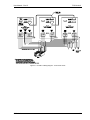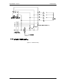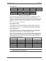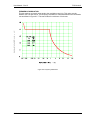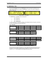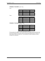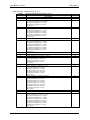
1
Revision B
December 2007
Copyright © 2007
by California Instruments.
All rights reserved.
P/N 5000-967
FCS Series II
AC Power Source
User Manual
TEL: +1 (858) 677-9040
FAX: +1 (858) 677-0940
Email: [email protected]
Web Site: http://www.calinst.com
User Manual – Rev B
FCS Series II
Refers to:
FCS Series II AC Power Source/Analyzers
Models:
Single chassis:
Multiple chassis:
FCS18-1, FCS18-3
FCS36-3, FCS54-3
Manual revision: B.
Copyright © 2007 California Instruments Company
California Instruments
2
User Manual – Rev B
FCS Series II
SAFETY SUMMARY
This power source contains high voltage and current circuits, which are potentially lethal.
Because of its size and weight, mechanical stability must be ensured. The following
safety guidelines must be followed when operating or servicing this equipment. These
guidelines are not a substitute for vigilance and common sense. California Instruments
assumes no liability for the customer’s failure to comply with these requirements. If the
power source is used in a manner not specified by California Instruments, the protection
provided by the equipment may be impaired.
BEFORE APPLYING POWER
1.
Verify the correct three phase input voltage is applied to the unit. Input ratings are shown
on the model and serial number tag located at the rear of the unit.
2.
The chassis and cabinet of this power source must be grounded to minimize shock hazard.
A chassis ground is provided at the input terminal block. This is located in the front of the
cabinet on the lower left hand side. The lower front cover panel must be removed to
access the line input and ground connections. The chassis ground must be connected to
an electrical ground through an insulated wire of sufficient gauge.
FUSES
Use only fuses of the specified current, voltage, and protection speed (slow blow, normal blow,
fast blow) rating. Do not short out the fuse holder or use a repaired fuse.
DO NOT OPERATE IN A VOLATILE ATMOSPHERE
Do not operate the power source in the presence of flammable gases or fumes.
DO NOT TOUCH ENERGIZED CIRCUITS
Disconnect the power cable before servicing this equipment. Even with the power cable
disconnected, high voltage can still exist on some circuits. Discharge these voltages before
servicing. Only qualified service personnel may remove covers, replace components or make
adjustments.
DO NOT SERVICE ALONE
Do not remove covers, replace components, or make adjustments unless another person, who
can administer first aid, is present.
DO NOT EXCEED INPUT RATINGS
Do not exceed the rated input voltage or frequency. Additional hazards may be introduced
because of component failure or improper operation.
DO NOT MODIFY INSTRUMENT OR SUBSTITUTE PARTS
Do not modify this instrument or substitute any parts. Additional hazards may be introduced
because of component failure or improper operation.
MOVING THE POWER SOURCE
When moving the power source, observe the following:
1.
Remove all AC power to unit.
2. Do not attempt to lift by hand. Raise the levelers and push the unit using two people to
prevent injury or use forklift equipment with a qualified operator.
ALLOW CAPACITORS TO DISCHARGE
Capacitors in the power source may hold a hazardous electrical charge even if the power source
has been disconnected from the mains supply. Allow capacitors to discharge to a safe voltage
before servicing internal circuits or touching exposed pins of the mains supply connectors.
California Instruments
3
User Manual – Rev B
FCS Series II
California Instruments
4
User Manual – Rev B
FCS Series II
WARRANTY INFORMATION
CALIFORNIA INSTRUMENTS CORPORATION warrants each instrument manufactured by them to be
free from defects in material and workmanship for a period of one year from the date of shipment to the
original purchaser. Excepted from this warranty are fuses and batteries that carry the warranty of their
original manufacturer where applicable. CALIFORNIA INSTRUMENTS will service, replace, or adjust
any defective part or parts, free of charge, when the instrument is returned freight prepaid, and when
examination reveals that the fault has not occurred because of misuse, abnormal conditions of
operation, user modification, or attempted user repair. Equipment repaired beyond the effective date of
warranty or when abnormal usage has occurred will be charged at applicable rates. CALIFORNIA
INSTRUMENTS will submit an estimate for such charges before commencing repair, if so requested.
VOIDED WARRANTY
Any misuse or abuse of, as well as any modifications or changes made to any California Instruments
product will automatically void the factory warranty. Removing non-normal use related covers or any
sealed covers or lids also automatically voids factory warranty unless express written or email
authorization is obtained from the customer service department in advance. The customer service
department can be reached via email at [email protected].
SERVICE PROCEDURE
If a fault develops, notify CALIFORNIA INSTRUMENTS at [email protected] or its local
representative, giving full details of the difficulty, including the model number and serial number. On
receipt of this information, service information or a Return Material Authorization (RMA) number will be
given. Add the RMA number furnished to the shipping label. Pack the instrument carefully to prevent
transportation damage, affix label to shipping container, and ship freight prepaid to the factory.
CALIFORNIA INSTRUMENTS shall not be responsible for repair of damage due to improper handling
or packing. Instruments returned without RMA No. or freight collect may be refused at California
Instruments discretion. Instruments repaired under Warranty will be returned either via prepaid surface
freight or low cost airfreight at California Instruments discretion. Instruments repaired outside the
Warranty period will be returned freight collect, Ex Works CALIFORNIA INSTRUMENTS 9689 Towne
Centre Drive, San Diego, CA 92121-1964. If requested, an estimate of repair charges will be made
before work begins on repairs not covered by the Warranty.
DAMAGE IN TRANSIT
The instrument should be tested when it is received. If it fails to operate properly, or is damaged in any
way, a claim should be filed immediately with the carrier. The claim agent should obtain a full report of
the damage, and a copy of this report should be forwarded to us by fax or email (Fax: 858 677 0940,
Email: [email protected]). CALIFORNIA INSTRUMENTS will prepare an estimate of repair cost
and repair the instrument when authorized by the claim agent. Please include model number and
serial number when referring to the instrument.
SPARE PARTS
To order spare parts, user manuals, or determine the correct replacement part for your California
Instruments products, please contact the Customer Service department by phone at + 1 858 677 9040,
press 2 or by email [email protected].
California Instruments
5
User Manual – Rev B
FCS Series II
Table of Contents
1. Introduction ................................................................................................................................... 10
1.1
1.2
General Description......................................................................................................................... 10
Manual organization and format ...................................................................................................... 11
2. Specifications ............................................................................................................................... 12
2.1
2.2
2.3
2.4
2.5
2.6
Electrical.......................................................................................................................................... 12
Mechanical ...................................................................................................................................... 18
Environmental ................................................................................................................................. 18
Front Panel Controls ....................................................................................................................... 19
Special Features ............................................................................................................................. 20
Available Options ............................................................................................................................ 21
3. Unpacking and Installation ........................................................................................................... 26
3.1
3.2
3.3
3.4
3.5
3.6
3.7
3.8
3.9
3.10
Unpacking ....................................................................................................................................... 26
Power Requirements ....................................................................................................................... 26
Mechanical Installation .................................................................................................................... 26
AC Input Wiring – TB1..................................................................................................................... 29
Output Connections......................................................................................................................... 31
Connectors - Rear Panel ................................................................................................................. 37
Basic Initial Functional Test............................................................................................................. 42
Multi-box Configurations (-MB Option) ............................................................................................ 44
Clock and Lock Mode (-LKM/-LKS Option)...................................................................................... 45
Remote Control Interfaces .............................................................................................................. 46
4. Front Panel Operation .................................................................................................................. 47
4.1
4.2
4.3
4.4
4.5
4.6
4.7
4.8
4.9
Tour of the Front Panel ................................................................................................................... 47
Menu Structure................................................................................................................................ 54
Output Programming ....................................................................................................................... 75
Waveform Management (-ADV Option required)............................................................................. 77
Measurements................................................................................................................................. 80
Harmonic Analysis........................................................................................................................... 81
Transient Programming................................................................................................................... 81
Setting the Power-on Initialization Values ....................................................................................... 86
Remote Inhibit Function .................................................................................................................. 87
5. Principle of Operation ................................................................................................................... 88
5.1
5.2
5.3
Overall Description .......................................................................................................................... 88
Controller Assembly ........................................................................................................................ 88
Power Amplifiers Assembly ............................................................................................................. 90
6. Calibration..................................................................................................................................... 94
6.1
6.2
6.3
6.4
6.5
6.6
6.7
Recommended Calibration Equipment ............................................................................................ 94
Calibration Screens ......................................................................................................................... 96
Measurement Calibration ................................................................................................................ 96
Output Calibration ........................................................................................................................... 99
Phase Offset Calibration ................................................................................................................. 99
Non-Routine Output Gain Calibration ............................................................................................ 100
Load Resistance by Model ............................................................................................................ 102
California Instruments
6
User Manual – Rev B
FCS Series II
7. Service ........................................................................................................................................ 103
7.1
7.2
7.3
7.4
7.5
7.6
7.7
7.8
Cleaning......................................................................................................................................... 103
General.......................................................................................................................................... 103
Basic operation .............................................................................................................................. 103
Isolating amplifier failures in multi-box systems ............................................................................. 106
Advanced Troubleshooting. ........................................................................................................... 107
Factory Assistance ........................................................................................................................ 110
Fuses............................................................................................................................................. 110
Replaceable Parts ......................................................................................................................... 111
8. Option -160: RTCA / DO-160D................................................................................................... 113
8.1
8.2
8.3
8.4
8.5
8.6
8.7
General.......................................................................................................................................... 113
Initial Setup .................................................................................................................................... 113
Tests Performed ............................................................................................................................ 113
Front Panel Operation -160 ........................................................................................................... 114
Normal State tests ......................................................................................................................... 115
EMERGENCY TEST ..................................................................................................................... 123
ABNORMAL TEST ........................................................................................................................ 125
9. Option –160: RTCA/DO-160 Rev E Tests (Software) ................................................................ 128
10. Option -704: MIL-STD 704 Rev D through F (MIL704 Mode) .................................................... 129
10.1
10.2
10.3
10.4
10.5
10.6
10.7
10.8
General.......................................................................................................................................... 129
Initial Setup .................................................................................................................................... 129
Test Revision ................................................................................................................................. 129
Tests Performed ............................................................................................................................ 130
Front Panel Operation MIL704....................................................................................................... 131
Steady State Tests ........................................................................................................................ 132
Emergency Test............................................................................................................................. 135
Abnormal Test ............................................................................................................................... 136
11. Option –704F: MIL-STD 704 Rev A through F (MS704 mode) .................................................. 138
11.1
11.2
11.3
11.4
11.5
11.6
11.7
11.8
General.......................................................................................................................................... 138
Initial Setup .................................................................................................................................... 138
Test Revision ................................................................................................................................. 138
Power Group Reference ................................................................................................................ 139
Available Tests .............................................................................................................................. 139
Front Panel Operation MS704 ....................................................................................................... 141
Test Steps and Execution Times Summary ................................................................................... 144
MS704 Operation Using the LxGui Software ................................................................................. 191
12. Option –ABD: Airbus ABD0100.1.8 Test (Software) .................................................................. 199
13. Option –AMD: Airbus AMD24C Test (Software) ........................................................................ 200
14. Option –B787: Boeing 787B3-0147 Test (Software) .................................................................. 201
15. Error Messages .......................................................................................................................... 202
16. Index ........................................................................................................................................... 208
California Instruments
7
User Manual – Rev B
FCS Series II
List of Figures
Figure 2-1: Distortion as a function of Output Frequency .................................................................................... 14
Figure 2-2: Current versus Voltage operating range. .......................................................................................... 15
Figure 2-3: Voltage / Frequency Rating............................................................................................................... 15
Figure 3-1: Rear Panel Connector Locations ...................................................................................................... 28
Figure 3-2: FCS36/2-3 Wiring diagram - Three Phase mode .............................................................................. 33
Figure 3-3: FCS36/2-1 Wiring diagram - Single Phase mode ............................................................................. 34
Figure 3-4: FCS54/3-3 Wiring Diagram - Three Phase mode ............................................................................. 35
Figure 3-5: FCS54/3-1 Wiring Diagram - Single Phase mode............................................................................. 36
Figure 3-6: USB Connector pin orientation.......................................................................................................... 40
Figure 3-7: Functional Test Setup ....................................................................................................................... 42
Figure 4-1: Shuttle Knob ..................................................................................................................................... 50
Figure 4-2: Menu Keys ........................................................................................................................................ 51
Figure 4-3: Measurement Screen........................................................................................................................ 53
Figure 4-4: PROGRAM Menu ............................................................................................................................. 58
Figure 4-5: CONTROL Menus............................................................................................................................. 59
Figure 4-6: MEASUREMENT Screen.................................................................................................................. 62
Figure 4-7: Selecting a Waveform....................................................................................................................... 77
Figure 4-8: Selecting Waveforms for Single Phase or All Phases....................................................................... 77
Figure 4-9: Waveform Crest Factor Affects Max. rms Voltage ............................................................................ 78
Figure 4-10: Pulse Transients ............................................................................................................................. 82
Figure 4-11: List Transients................................................................................................................................. 82
Figure 4-12: Sample Transient Output Sequence ............................................................................................... 84
Figure 4-13: Switching Waveforms in a Transient List ........................................................................................ 85
Figure 4-14: TRANSIENT Menu.......................................................................................................................... 85
Figure 5-1: FCS System Block Diagram.............................................................................................................. 89
Figure 5-2: Power Amplifier - Exploded View. ..................................................................................................... 92
Figure 6-1: Calibration Setup .............................................................................................................................. 95
Figure 6-2: Current Limit board access panel ................................................................................................... 100
Figure 6-3: Location of Gain pot adjustments and TP1 through TP4 ................................................................ 100
Figure 7-1: Front panel location ........................................................................................................................ 109
Figure 7-2: Fuse Locations................................................................................................................................ 109
Figure 8-1: Application Menu ............................................................................................................................ 114
Figure 8-2: DO160 Main Menus ........................................................................................................................ 114
Figure 8-3: Normal state screens ...................................................................................................................... 115
Figure 8-4: Voltage Modulation - Frequency characteristics ............................................................................. 118
Figure 8-5: Frequency Modulation..................................................................................................................... 119
Figure 8-6: Power Interrupt ............................................................................................................................... 120
Figure 8-7: Power Interrupt for Group2/A(NF) and Group3/A(WF).................................................................... 121
Figure 8-8: Emergency Screens........................................................................................................................ 123
Figure 8-9: Abnormal Screen ............................................................................................................................ 125
Figure 10-1: Applications Menu......................................................................................................................... 131
Figure 10-2: MIL704 Menu ................................................................................................................................ 131
Figure 10-3: Steady State Menu ....................................................................................................................... 132
Figure 10-4: Emergency Menu.......................................................................................................................... 135
Figure 10-5: Abnormal Screens ........................................................................................................................ 136
Figure 11-1: Applications Menu......................................................................................................................... 141
Figure 11-2: MIL704 Run/Status ....................................................................................................................... 141
Figure 11-3: Mil704 Run/Status......................................................................................................................... 141
Figure 11-4: Revision/Group Menu ................................................................................................................... 142
Figure 11-5: Test selection Menu...................................................................................................................... 142
Figure 11-6: Section and Test Condition ........................................................................................................... 143
Figure 11-7:Steady State frequency.................................................................................................................. 143
Figure 11-8: Required SAC-106 Test Setup...................................................................................................... 146
Figure 11-9: Required TAC-106 Test Setup...................................................................................................... 159
Figure 11-10: Required SVF-106 Test Setup. ................................................................................................... 172
Figure 11-11: Required TVF-106 Test Setup. ................................................................................................... 180
Figure 11-12: Required SXF-106 Test Setup. ................................................................................................... 187
Figure 11-13: LxGui MS704 Option Screen ...................................................................................................... 192
Figure 11-14: LxGui MS704 Option EUT Performance Test Screen - Measurements ...................................... 193
California Instruments
8
User Manual – Rev B
FCS Series II
Figure 11-15: LxGui MS704 Option EUT Performance Test Screen - Waveforms ............................................ 195
List of Tables
Table 3-1: AC Input transformer, EMI Filter and CB configurations.....................................................................30
Table 3-2: FCS18 Rear Panel Connections.........................................................................................................31
Table 3-3: Wire Gauge table................................................................................................................................32
Table 3-4: Output Terminal connections..............................................................................................................32
Table 3-5: AC Input Terminal Block Connection Description ...............................................................................37
Table 3-6: External Sense Connector..................................................................................................................37
Table 3-7: Output Terminal connections..............................................................................................................37
Table 3-8: DB15 Auxiliary I/O Connector.............................................................................................................38
Table 3-9: BNC Connectors.................................................................................................................................38
Table 3-10: RS232C Connector ..........................................................................................................................39
Table 3-11: USB Connector pin out. ....................................................................................................................40
Table 3-12: RJ45 LAN Connector pin out. ...........................................................................................................41
Table 3-13: Full Load Resistance. .......................................................................................................................43
Table 4-1: Menu Tree ..........................................................................................................................................57
Table 4-2: Sample Transient List.........................................................................................................................84
Table 4-3: Factory Default Power on Settings .....................................................................................................86
Table 4-4: Factory Default Power on Settings .....................................................................................................87
Table 6-1: Calibration Load Values by model and voltage range.........................................................................97
Table 6-2: Output Calibration Coefficients - Factory Defaults..............................................................................99
Table 6-3: Output Calibration Coefficients - Factory Defaults............................................................................ 101
Table 7-1: Basic Symptoms............................................................................................................................... 103
Table 7-2: Replaceable Parts and Assemblies .................................................................................................. 112
Table 8-1: Normal Voltage and Frequency minimum......................................................................................... 116
Table 8-2: Normal Voltage and Frequency Maximum ........................................................................................ 116
Table 8-3: Normal Voltage Unbalance............................................................................................................... 117
Table 8-4: Airbus mode voltage modulation. ..................................................................................................... 117
Table 8-5: Normal VoltageSurge Sequence ...................................................................................................... 121
Table 8-6: Normal Frequency Transient Sequence ........................................................................................... 122
Table 8-7: Normal Frequency Variation Sequence ............................................................................................ 122
Table 8-8: Emergency Voltage and Frequency Minimum .................................................................................. 123
Table 8-9: Emergency Voltage and Frequency Maximum ................................................................................. 123
Table 8-10: Emergency Voltage Unbalance ...................................................................................................... 124
Table 8-11: Abnormal Voltage Minimum............................................................................................................ 125
Table 8-12: Abnormal Voltage Maximum........................................................................................................... 125
Table 8-13: Abnormal Voltage Unbalance ......................................................................................................... 126
Table 8-14: Abnormal Frequency Transient ...................................................................................................... 127
Table 10-1: Steady state voltage ....................................................................................................................... 132
Table 10-2: Steady state frequency ................................................................................................................... 133
Table 10-3: Frequency Modulation .................................................................................................................... 133
Table 10-4: Abnormal Over Frequency.............................................................................................................. 137
Table 10-5: Abnormal Under Frequency............................................................................................................ 137
Table 11-1: DO160 Test Groups ....................................................................................................................... 139
Table 11-2: Test Selections ............................................................................................................................... 142
Table 11-3: Steady state frequency ................................................................................................................... 143
Table 15-1: Error Messages .............................................................................................................................. 207
California Instruments
9
User Manual – Rev B
FCS Series II
1. Introduction
This instruction manual (P/N 5000-967) contains information on the installation, operation,
calibration and maintenance of the FCS Series II AC power sources.
FCS Series II models are different from the original FCS Series in the following areas:
•
New higher performance controller with arbitrary waveform capability is used.
•
Standard RS232 and USB interfaces have been added in addition to GPIB.
•
Optional Ethernet LAN interface is available. (Option –LAN).
•
The front panel keyboard display is more user friendly with full decimal keypad for data
entry.
•
Number of available output voltage range options has been reduced to 135/270
(standard), 156/312 or 200/400.
1.1 General Description
The FCS Series II AC Power Source is a high efficiency, cabinet AC Power Source/Analyzer
combination that provides a precise output and advanced measurements. Standard output
voltage ranges are 135 Vac and 270 Vac RMS. The FCS II Series is available in either single (1) or three-phase (-3) mode. Three phase units offer an optional single-phase mode for both
modes of operation.
For power levels above 18 KVA, two or more FCS series units can be combined using the
system interface in a parallel mode of operation. These multi chassis systems consist of one
master unit with controller and one or two auxiliary units without controllers. Only the master unit
has a front panel keyboard and display.
Read the installation instructions carefully before attempting to install and operate the FCS
Series II power systems.
California Instruments
10
User Manual – Rev B
FCS Series II
1.2 Manual organization and format
All user documentation for California Instruments power sources is provided on CDROM in
electronic format. (Adobe Portable Document Format) The required Adobe PDF viewer is
supplied on the same CDROM. This manual may be printed for personal use if a hardcopy is
desired. To request a hardcopy from California Instruments, contact customer service at
[email protected]. There will be an additional charge for printed manuals.
This manual contains sections on installation, normal use, maintenance and calibration. The
FCS Series II is equipped with GPIB, USB and RS232C interfaces. A LAN interface can be
specified at the time of order. Refer to the Lx/Ls Series II Programming manual for information
on using the remote control interface and command syntax. The programming manual (P/N
7004-981) is provided on the same CDROM as this user manual.
California Instruments may make updated versions of this manual available from time to time in
electronic format through it’s website. To obtain an updated manual revision if available, check
the California Instruments Manual download page at www.calinst.com. You need to register as a
customer to obtain free access to manual and software downloads.
California Instruments
11
User Manual – Rev B
FCS Series II
2. Specifications
Specifications shown are valid over an ambient temperature range of 25 ± 5° C and apply after a
30 minute warm-up time. Unless otherwise noted, all specifications are per phase for sine wave
output into a resistive load. For three phase configurations or mode of operation, all
specifications are for Line to Neutral (L-N) and phase angle specifications are valid under
balanced load conditions only.
2.1 Electrical
2.1.1 Input
Parameter
Specification
Line Voltage:
(3 phase, 3 wire
+ ground (PE))
Standard: 208 VAC ± 10 %
Line VA:
(total)
24 KVA. at nominal input voltage.
Line Current:
(per phase)
65 Arms @ 208 VAC
56 Arms @ 240 VAC
36 Arms @ 380 VAC
33 Arms @ 415 VAC
28 Arms @ 480 VAC
Note: Each FCS chassis requires its
own AC service.
Optional: 240 VAC ± 10%
380 VAC ± 10%
415 VAC ± 10%
480 VAC ± 10%
Currents shown are for single chassis models and per phase. For multichassis configurations, currents are per chassis.
Line Frequency:
47- 63 Hz
Efficiency:
85 % (typical) depending on line and load
Power Factor:
Inrush Current:
0.85 (typical)
250 Apk max.
Hold-Up Time:
> 10 ms
Isolation
Voltage:
400 VAC RMS input to output
California Instruments
Note: Each FCS chassis
requires its own AC service.
1350 VAC input to chassis
12
User Manual – Rev B
FCS Series II
2.1.2 Output
Output Parameter
Specification
AC
Modes
Voltage:
Standard Voltage
Ranges (L-N):
Low range: 0 – 135 Vac
High range: 0 – 270 Vac
Resolution:
Programming
Accuracy:
Distortion THD (to 80
Khz)1:
0.1 V
± (0.05% + 0.25 V) from 10V to FS.
Specified at voltage sense point with ALC mode ON.
< 1 % from 50 Hz to 60 Hz.
See for distortion as a function of frequency.
Load Regulation:
ALC mode ON
0.1 % FS
External Sense
Up to 2% of Full scale voltage can be dropped across each load lead Internal
or External sense selectable.
Line Regulation:
0.1% for 10% input line change
Stability:
± 0.05% FS, 24 hours, constant line, load and temperature, ALC on.
Temp Coefficient:
± 0.05 V/°C
DC Offset Voltage:
0.0 V
Output Noise:
(20 kHz to 1 MHz)
Low voltage range: < 425 mVRMS
High voltage range: < 950 mVRMS
Output Coupling
Transformer coupled
Output Impedance (Z)
Z = Vrange * 0.001 / I_load
Power (total power per phase, either range, at full scale voltage)
FCS18-1 (single phase)
FCS18-3 (three phase)
18 kVA
6 kVA
FCS18-1 (single phase)
FCS18-3 (three phase)
135 V Range.
133.2 Arms
44.4 Arms
270 V Range.
66.6 Arms
22.2 Arms
At 35° C ambient max.
Current
Model
Note:
Current derates linearly from 50% of voltage range to 10% of specified current at 10% of
voltage range. See Figure 2-2 for specified current versus voltage operating range.
Note:
Current, maximum amps per phase available. For FCS36/2, currents are times two. For
FCS54/3, currents are times three. 35° C ambient max.
Current Limit mode
Programmable, CC or CV mode
Repetitive Peak Current
1
135 V Range.
375 Apk
125 Apk
270 V Range.
187.5 Apk
62.5 Apk
The distortion specification for the FCS II Series applies at full-scale voltage, full resistive load conditions.
California Instruments
13
User Manual – Rev B
FCS Series II
Output Parameter
Specification
Frequency
Range:
45 Hz - 1200 Hz [Standard, -HV option]
45 Hz – 1000 Hz [-EHV option]
Supplemental
Operation from 17 to 45 Hz is available at reduced output voltage.
Vout max = 100 % * F /45 for F < 45Hz. See chart Figure 2-3 for
Voltage/Frequency rating.
Resolution1:
0.01 Hz
0.1 Hz
1 Hz2
[< 81.91 Hz]
[> 82.0 to 819.1 Hz]
[> 819 Hz]
Accuracy:
± 0.025 %
Temp. Coefficient
± 5 ppm of value / °C
Stability:
± 15 ppm of value
Phase (3 phase mode)
Range:
Phase B/C relative to phase A
0.0 to 360.0°
Resolution:
0.1° < 819.1 Hz
0.5° > 819.1 Hz
Accuracy:
< 1°
<2
[45 Hz - 1000 Hz]
[1000 Hz – 1200 Hz]
Distortion (% THD)
4.50
4.00
3.50
3.00
2.50
2.00
1.50
1.00
0.50
0.00
10
100
1000
10000
Output Frequency
Figure 2-1: Distortion as a function of Output Frequency
1
Programming resolution reduced if –LKM/-LKS option is installed. See paragraphs 2.6.3.
Programming resolution of 0.5 Hz above 819.1 Hz may be used over the remote control bus with ± 0.5 Hz
accuracy.
2
California Instruments
14
OUTPUT CURRENT (% FS)
User Manual – Rev B
FCS Series II
100
75
50
OPERATING RANGE
25
10
10
50
75
100
OUTPUT VOLTAGE (% FS)
Figure 2-2: Current versus Voltage operating range.
Vout max.
in % FS
100%
50%
38%
17 Hz
45 Hz
Frequency
Max.
Figure 2-3: Voltage / Frequency Rating
California Instruments
15
User Manual – Rev B
FCS Series II
2.1.3 AC Measurements
Measurement specifications apply to single chassis FCS Series II AC source in three-phase
mode. See notes for other models and configurations.
Parameter
Range
Accuracy (±)
1 Phase Mode
1
Resolution
3 Phase Mode
Frequency
45.00-1200.0 Hz
0.1% ± 1 digit
Phase
45.00 - 100.0 Hz
100.0 - 1200 Hz
0.5°
2°
RMS Voltage
0 - 400 Volts
RMS Current
0 - 150 Amps
0.1% + 0.45A
0.1% + 0.15A
0.001 Amp
Peak Current
0 - 250 Amps
0.2% + 1.5A
0.1% + 0.45A
0.001 Amp
Crest Factor
1.00 – 10.00
1.5 %
1.5 %
0.01
VA Power
0 - 6 KVA
0.3% + 15 VA
0.15% + 5 VA
1 VA
Real Power
0 - 6 KW
0.3% + 15 W
0.15% + 5 W
1W
Power Factor
0.00 - 1.00
0.03
0.01
0.01
0.05% + 0.25V
0.01 Hz to 81.91 Hz
0.1 Hz to 819.1 Hz
1 Hz > 819.1 Hz
0. 1°
0.01 Volt
Note: Accuracy specifications are valid above 100 counts. For multi-chassis configurations, Current
and Power range and accuracy specifications are times the number of chassis.
Note: Frequency measurement specification valid for output > 20 Vrms.
Note: Crest Factor accuracy applies for Irms > 50% of max.
Note: Power Factor accuracy applies for PF > 0.5 and VA > 50% of max.
2.1.4 Harmonic Measurements
Harmonic measurement specifications apply to FCS18-3 with –ADV option in three-phase
mode. See notes for single-phase mode or FCS18–1 with –ADV option.
Parameter
Range
Accuracy (±)
Resolution
Frequency fundamental
45.00 - 81.91 Hz
82.0 - 819.1 Hz
> 819.1 Hz
0.1% ± 1 digit
0.01 Hz
0.1 Hz
1 Hz
Frequency harmonics
45.00 Hz – 16 kHz
0.1% + 2 digits
0.1 Hz
0 - 400 Volts
0.05% + 0.25V
0.01V
0.1% + 0.1%/kHz + 0.25
0.01V
0.1% + 0.15A
0.01A
0.1% + 0.1%/kHz + 0.05A
0.01A
Voltage
Fundamental
Harmonic 2 - 50
Current
Fundamental
Harmonic 2 - 50
0 - 20 Amps
Note: Current range and accuracy specifications are times three in single-phase mode. For multichassis configurations, current accuracy specifications are times the number of chassis. The harmonic
measurement bandwith increases to 48Khz in single-phase mode.
1
Frequency measurement specifications valid with output voltage of 30Vrms or higher. If output relay is open,
frequency measurement will return 0.0 Hz.
California Instruments
16
User Manual – Rev B
FCS Series II
2.1.5 System Specification
Parameter
Specification
Trigger Input:
External trigger source input. Requires TTL level input signal. Triggers
on negative edge. Response time 80 - 100 µs.
Non volatile memory
storage:
16 complete instrument setups and transient lists, 100 events per list.
50 User defined waveforms.
Waveforms
Standard:
with –ADV option:
Transients
Voltage: drop, step, sag, surge, sweep
Sine
Sine, square, clipped, user defined
Frequency: step, sag, surge, sweep
Voltage and Frequency: step, sweep
Current Limit Modes:
Two selectable modes of operation:
1.
Constant current mode (voltage folds back with automatic recovery)
2.
Constant voltage mode with trip-off (Relays open).
Interfaces
IEEE-488
AH1, DC1, DT1, L3, RL2, SH1, SR1, T6
IEEE 488.2 and SCPI
Response time is 10 ms (typical)
LAN / Ethernet
(-LAN Option)
RJ45 Connector, 10BaseT, 100BaseT or 1000BaseT,
Data transfer rate: 460,800 bps
Protocol: TCP/IP.
Note: If –LAN is installed, RS232C interface is disabled.
RS232C
Baud rates, 9600, 19200, 38400, 57600 and 115200
Data bits: 8, Start bits: 1, Stop bits: 1, Parity: None
Syntax: SCPI
Response time is 10 ms (typical @ 115200 baud)
USB
Standard USB peripheral.
Data transfer rate: 460,800 bps
Syntax: SCPI
Note: Use of the USB port to control more than one power
source from a single PC is not recommended, as communication
may not be reliable. Use GPIB interface for multiple power source
control.
2.1.6 Unit Protection
Parameter
Specification
Input Over current:
Input Circuit breaker. This breaker protects the equipment only and is not
a branch protection device. AC input connection should be make using a
suitable branch protection device per local electrical code.
Input Over voltage
Transients:
Surge protection to withstand EN50082-1 (IEC 801-4, 5) levels.
Output Over current:
Adjustable level constant current mode with programmable set point.
Output Short Circuit:
Peak and RMS current limit.
Over temperature:
Automatic shutdown.
California Instruments
17
User Manual – Rev B
FCS Series II
2.2 Mechanical
Parameter
Dimensions:
Specification
Floor standing Cabinet on casters:
Height:
45 inches (114.3 cm)
Depth:
36 inches + 4 inches for J-box = 40 inches (101.6 cm)
Width:
30 inches (76.2 cm)
All dimensions are per chassis. For /2 or /3 model configurations,
multiply height by 2 or 3 for total height.
Unit Weight:
Per chassis
Net:
900 lbs / 87.7 Kg approximately
Shipping:
1100 lbs / 127.3 Kg approximately
All weights are per chassis. For /2 or /3 model configurations, each
chassis is packaged individually.
Material:
Steel chassis with steel side panels.
Finish:
Powder coated.
Color: medium gray.
Cooling:
Fan cooled with front air intake and rear exhaust.
Variable speed fan control.
Acoustic Noise
(Supplemental
specification)
Measured at 1 m distance:
Fan speed:
Low power mode
Full power mode
Front of unit:
65 dBA
70 dBA
Rear of unit:
62 dBA
67 dBA
Internal Construction:
Modular sub assemblies.
Rear Panel
Connections:
(See section 3 for description of connections)
•
AC input wiring
•
AC output wiring
•
External sense terminal block (Remote voltage sense)
•
System interface (2x)
•
GPIB, USB, LAN (option) and RS232C
•
Auxiliary I/O connector. (High density DB15)
2.3 Environmental
Parameter
Specification
Operating Temp:
0° to +35° C, full power, 0° to +50° C, reduced power
+32° to +95° F, full power, +32° to +122° F, reduced power.
Storage Temp:
-40° to +85 °C.
-40° to +185° F.
Altitude:
< 2500 meters
< 7500 feet
Relative Humidity:
0-95 % RAH, non-condensing maximum for temperatures up to 31°C
decreasing linearly to 50% at 40°C.
Indoor Use Only
California Instruments
18
User Manual – Rev B
Parameter
FCS Series II
Specification
Vibration:
Designed to meet NSTA project 1A transportation levels using CI
provided packing crate.
Shock:
Designed to meet NSTA project 1A transportation levels using CI
provided packing crate.
2.4 Front Panel Controls
Controls:
Shuttle knob:
Shuttle knob may be used to adjust voltage, current limit and frequency
for selected phase or all three phases while in the SET menu. In all other
menu's, the shuttle may be used to change parameter values and
settings.
Numeric Keypad
Keys 0 through 9, decimal point, and +/- sign key may be used to enter
any numeric data value.
Up/down arrow keys:
A set of up and down arrow keys is used to move the cursor position in
all menus. This allows quick selection of the desired function or
parameter.
Function keys:
Set key will show output voltage and frequency setting.
Meas key displays the measurement screens. Measure key will display
measurement values for selected phase or phase A if all three phases
are selected.
Menu key selects main menu.
Enter key is used to confirm selections.
Back key is used to back up to previous screen.
Output on/off key for output relay control.
Phase key toggles between phase A, B, C or all phases selection.
Displays:
LCD graphics display:
Large high contrast backlit LCD display. An adjustable viewing angle
makes it easy to read from all practical locations.
Status indicators:
Large and bright status indicators inform the user of important power
source conditions.
The Remote lamp informs the user that the unit is under remote control.
The Overload lamp indicates that excessive current is being drawn at the
output.
The Over temperature lamp illuminates when internal heat sink
temperatures are too high.
The Hi Range indicator is lit any time the unit is switched to the high
voltage range.
The Output On/Off indicator is on when the power source output relays
are closed.
The Phase A, B and C indicators are lit when the relevant phase is
selected with the Phase key.
California Instruments
19
User Manual – Rev B
FCS Series II
2.5 Special Features
Controller Features
Mode:
Switches between 1 and 3 phase outputs.
Parallel Operation:
FCS36 and FCS54 systems use two or three chassis in parallel
operation. The two or three chassis must be connected using the system
interface cable supplied with the system.
Controller:
Programmable controller front panel assembly.
Output Relay:
Standard output relay feature to isolate power source from the load.
Output On/Off:
The output relay can be used to quickly disconnect the load. A yellow
status indicator displays the status of the output relay. Relay is either
through front panel button or using Remote Inhibit input signal.
External Trigger Output
or Function Strobe
An external TTL output is available which may be used to trigger other
equipment. The TTL output can be controlled by the transient
programming system. This requires the trigger mode to be set to EXT
(factory default). This can only be done over the bus using the
OUTP:TTLT:MODE TRIG command.
It can also be configured to generate an output pulse any time the
voltage, frequency, current limit or phase programming is updated. This
requires the trigger mode to be set to FSTR. This can only be done over
the bus using the OUTP:TTLT:MODE FSTR command. This mode is
compatible with the CI FCS Series I.
The Trigger Output / function strobe is an active low TTL signal with a
duration of no less than 400 usec.
Clock and Lock Mode
Enables two or more independent FCS II power systems to be phase
synchronized to each other. One system (-LKM) acts as the master, the
other(s) (-LKS) as auxiliaries. The –LKS units are synced to the –LKM
unit. Refer to section 3.9 for details on Clock and Lock mode.
Trigger Input
A TTL input signal may be used as an external trigger source for output
changes programmed on the AC power source transient system. This
requires the trigger source to be set to EXT. This can only be done over
the bus.
California Instruments
20
User Manual – Rev B
FCS Series II
2.6 Available Options
AC Input Voltage Options
Line input:
Must be specified at time of order. Refer to section 3.4.1
- 208
208V L-L AC nominal, 3 phase
- 240
240V L-L AC nominal, 3 phase
-380
380V L-L AC nominal, 3 phase
-415
415V L-L AC nominal, 3 phase
-480
480V L-L AC nominal, 3 phase
- HV
156 / 312 V range output
- EHV
200 / 400 V range output
Output Options
-LF
-MODE
Low frequency option. Limits maximum output frequency to 500 Hz.
Adds single phase and three-phase mode switching capability to FCS183 models. Not available on FCS18–1 or FCS36-3 and FCS54-3 models.
Firmware Options
- 160
RTCA/DO-160D test firmware.
Includes RCTA-DO160D, section 16, Change #2 and EURO/CAE-14D
AC tests only.
- 704
Mil Std 704 test firmware – MIL704
Includes AC tests for Revisions D and E
- 704F
Mil Std 704 test firmware – MS704
Includes AC tests for Revisions A through F
-ABD
Airbus ABD0100.1.8 Tests. – ABD
Includes tables A, B and C.
This option can only be used with the provided LxGui Windows software.
-AMD
Airbus AMD24C Tests. – AMD
Revision C.
This option can only be used with the provided LxGui Windows software.
-B787
Boeing 787B3-0147 Tests. – B787
This option can only be used with the provided LxGui Windows software.
-ADV
Advanced features package. Adds arbitrary waveform generation and
harmonic analysis measurements.
-EXS
External Sync (see Notes)
-LAN
Ethernet LAN interface connection. RJ45 connector.
Note: When installed, RS232C interface is disabled.
-LKM
Clock and Lock Master. Enables synchronizing outputs of two AC
sources, one acts as master.
This mode supports a frequency range of 45 to 819 Hz. See section 3.9.
-LKS
Clock and Lock Auxiliary. See -LKM for details. (See Notes, see section
3.9.)
Misc. Options
-MB
California Instruments
Multi-box option. Provides additional controller(s) on FCS36/2 or FCS54/3
configurations allowing system to be separated into individual functional
21
User Manual – Rev B
FCS Series II
units.
Notes:
External Trigger input is standard.
External Trigger input and External sync are mutually exclusive.
Units with -LKS (auxiliary) cannot have External Sync.
2.6.1 -HV Option - Supplemental Specifications
Specifications for FCS units with -HV voltage range option installed are same as standard FCS
except where noted below.
Frequency
Range:
45 Hz - 1200 Hz
Voltage:
Ranges (L-N):
Low range
0 - 156 Vrms
High range
0 - 312 Vrms
Current
Model
FCS18-1-HV (single phase)
FCS18-3-HV (three phase)
156 V Range.
115.2 Arms
38.4 Arms
312 V Range.
57.6 Arms
19.22 Arms
Note:
Current derates linearly from 50% of voltage range to 20% of specified current at 10% of
voltage range.
Note:
Current, maximum amps per phase available. For FCS36/2, currents are times two. For
FCS54/3, currents are times three. 35° C ambient max.
Repetitive Peak Current
156 V Range.
325 Apk
108 Apk
312 V Range.
162 Apk
54 Apk
California Instruments
22
User Manual – Rev B
FCS Series II
2.6.2 -EHV Option - Supplemental Specifications
Specifications for FCS units with -EHV voltage range option installed are same as standard FCS
unit except where noted below.
Frequency
Range:
45 Hz - 1000 Hz
Voltage:
Ranges (L-N):
Low range
0 - 200 Vrms
High range
0 - 400 Vrms
Current
Model
FCS18-1-HV (single phase)
FCS18-3-HV (three phase)
200 V Range.
90 Arms
30 Arms
400 V Range.
45 Arms
15 Arms
Note:
Current derates linearly from 50% of voltage range to 20% of specified current at 10% of
voltage range.
Note:
Current, maximum amps per phase available. For FCS36/2, currents are times two. For
FCS54/3, currents are times three. 35° C ambient max.
Repetitive Peak Current
200 V Range.
250 Apk
84 Apk
400 V Range.
125 Apk
42 Apk
California Instruments
23
User Manual – Rev B
FCS Series II
2.6.3 -LKM and -LKS Options - Supplemental Specifications
The Clock and Lock option enables two independent FCS power systems to be phase synchronized to
each other. One system (-LKM) acts as the master, the other(s) (-LKS) as auxiliaries. The –LKS units are
synced to the –LKM unit. Refer to section 3.9 for details on Clock and Lock mode. Note that the maximum
number of auxiliary units (-LKS) per master (-LKM) is one. No T connectors are allowed to increase the
number of auxiliary units as this may cause reflections on the clock and lock signals.
Note:
It is not possible to mix Series I FCS units and Series II FCS units in a clock and
lock configuration. Both models must be of the same series.
The following supplemental specifications apply when the Ls is configured with the Clock and Lock option.
(-LKM or –LKS).
Parameter
Supplemental Specification
Voltage
Voltage Distortion
Standard specifications apply.
Frequency
Range
Resolution
Accuracy
45 – 1200 Hz (Standard, -HV)
45 – 1000 Hz (-EHV)
0.1 Hz
± 0.025%
Phase
Phase Resolution
Standard specifications apply.
Phase Accuracy
Standard specifications apply.
California Instruments
24
User Manual – Rev B
FCS Series II
2.6.4 –EXS Option - Supplemental Specifications
The –EXS (External Sync) option allows the output frequency of the AC source to be synchronized to an
external TTL level clock signal.
The following supplemental specifications apply when the FCS II is configured with the external sync option.
(-EXS).
Parameter
Supplemental Specification
Input
Voltage Input
Impedance
TTL Level square wave.
10 KOhm.
Frequency
Range
Max Sync Input Slew Rate
Max Sync Step
Same as internal clock mode. See configuration limits.
< 80 Hz / sec.
Changes in sync input frequency occurring faster than this rate will result in
Error 804: External Sync Error. Output relay is opened on Error.
< 20 Hz.
Sudden changes in sync input frequency greater than 20 Hz will result in
Error 804: External Sync Error. Output relay is opened on Error.
Mode Selection
When switching between INT and EXT sync mode, the output of the AC
source will be dropped momentarily.
Restrictions
Frequency cannot be programmed in external sync mode.
Frequency transient list system is not available in sync mode.
Transient list dwell times are not correlated to external sync but based on
internal timebase.
California Instruments
25
User Manual – Rev B
FCS Series II
3. Unpacking and Installation
3.1 Unpacking
Inspect the unit for any possible shipping damage immediately upon receipt. If damage is
evident, notify the carrier. DO NOT return an instrument to the factory without prior approval.
Do not destroy the packing container until the unit has been inspected for damage in shipment.
If possible, retain the container in the event the system ever has to be returned to the factory for
either repair of upgrades.
A forklift should be used to remove the FCS cabinet from its shipping crate. Once on a level
floor, the cabinet can be pushed in place using it’s own casters. Levelers at each corner may be
used to prevent the unit from moving. Levelers are not intended to support the entire weight of
the cabinet howewer.
WARNING: This power source weighs approximately 900 lbs / 400 Kg per chassis.
Obtain adequate help when moving or installing the unit. Make sure the floor on
which the FSC II Series unit is installed can support the weight of the unit.
3.2 Power Requirements
The FCS Series II power Source has been designed to operate from a three-phase, three wire
(Wye or Delta) AC input line. A protective earth connection is required as well. (PE).
Available three-phase input setting is 208 VLL nominal for standard FCS18 models or 230, 380,
415 or 480 VLL with optionally configured input settings. All three phase input is three wire plus
ground.
CAUTION: Do not connect 400Vor 480V into a unit designed for 208V use. The result
could be a severely damaged unit. Always check the input rating on the model
number tag before connecting AC input power. AC voltage input settings CANNOT
be changed in the field. Contact California Instrument customer service to obtain
support for input reconfiguration.
3.3 Mechanical Installation
The FCS II Series AC power sources can be used free standing on a solid surface. The units
are fan cooled, drawing air in from the front and exhausting at the rear. The back of each unit
must be kept clear of obstruction and a 6” clearance must be maintained to the rear. Special
consideration of overall airflow characteristics and the resultant internal heat rise must be
considered at all times to avoid self heating and over temperature problems.
Multi chassis configurations such as the FCS36/2 or FSC54/3 consist of two or three selfcontained FCS18 power sources. They must be connected through the system interface using
the supplied DB25 to DB25 cable. Output wiring from each chassis to the EUT must be of equal
wire gage and length to ensure proper current sharing between units.
Note that for multi-chassis systems, it is recommended to turn the Master unit ON first and then
the Auxiliary unit(s). To turn the system off, turn OFF the Auxiliary unit(s) first and then the
Master unit.
California Instruments
26
User Manual – Rev B
FCS Series II
California Instruments
27
User Manual – Rev B
FCS Series II
Figure 3-1: Rear Panel Connector Locations
California Instruments
28
User Manual – Rev B
FCS Series II
3.4 AC Input Wiring – TB1
AC input connections are to be made directly to the input terminal block (TB1) of all units that
make up an FCS system. The input block is located on the lower right hand corner of the back
of the FCS18 chassis when facing the back. It is labeled “TB1” and “INPUT”. To connect AC
input wiring, remove the safety cover from the input junction box using a screwdriver to gain
access to the terminal block.
A Ground (earth) wire must be connected to the chassis of the AC power system using the
ground connection of the AC input connecter block. The mains source must have a current
rating equal to or greater than the input circuit breaker and the input wiring must be sized to
satisfy the applicable electrical codes. Consult a qualified electrician prior to installation. Note
that all wires must be sized to accommodate the worst-case maximum current that may occur
under low line conditions. Local electrical codes may also require different wire types and sizes.
Cable lengths must not exceed twenty-five (25) feet. For lengths greater than 25 feet, calculate
the voltage drop from the following formula:
2 X DISTANCE X CABLE RESISTANCE PER FT. X CURRENT = VOLT DROP
CAUTION: Capacitors in the power source may hold a hazardous electrical charge
even if the power source has been disconnected from the mains supply. Allow
capacitors to discharge to a safe voltage before touching exposed pins of mains
supply connectors. Power modules need at least 10 Minutes to discharge to safe
levels before they can be removed.
California Instruments
29
User Manual – Rev B
FCS Series II
3.4.1 AC Input Voltage Taps
The factory configured input voltage is shown in the serial tag label at the back of the power
source cabinet. If it is required to change the factory set input voltage configuration, a new EMI
filter and circuit breaker may have to be installed depending on what filter and breaker was
originally installed. Refer to the table below for input wiring configuration settings and EMI filter
and CB part numbers.
NOMINAL INPUT
VOLTAGE
TRANSFORMER
CONNECTIONS
CIRCUIT
BREAKER
EMI FILTER
208
(187 - 229)
Jumper 1, 5, 19, 23
Jumper 3, 7, 9, 13
Jumper 11, 15, 17, 21
100 amp
270162
250558
240
(216 - 264)
Jumper 1, 5, 20, 24
Jumper 4, 8, 9, 13
Jumper 12, 16, 17, 21
100 amp
270162
250558
380
(342 - 418)
Jumper 1, 22
Jumper 2, 5
Jumper 6, 9
Jumper 10, 13
Jumper 14, 17
Jumper 18, 21
50 amp
270175
250567
415
(374 - 456)
Jumper 1, 23
Jumper 3, 5
Jumper 7, 9
Jumper 11, 13
Jumper 15, 17
Jumper 19, 21
50 amp
270175
250567
480
(432 - 528)
Jumper 1, 24
Jumper 4, 5
Jumper 8, 9
Jumper 12, 13
Jumper 16, 17
Jumper 20, 21
50 amp
270175
250567
Table 3-1: AC Input transformer, EMI Filter and CB configurations.
Note:
For 220V or 230V nominal input voltages, use the 240V nominal input tap setting.
California Instruments
30
User Manual – Rev B
FCS Series II
3.5 Output Connections
3.5.1 Output Wiring
The output terminal block (TB3) for each chassis is located at the rear of the unit to the left when
facing the rear. Three phase output connections are made to the terminal block labeled “TB3”
and “OUTPUT”. For mulit-box systems, the output terminals from the master FCS18 and the
Auxiliary FCS18(s) must be connected together using the provided marathon block and equal
length wires.
Table 3-2: FCS18 Rear Panel Connections
The phase outputs are labeled øA, øB, øC and NEUT. If the power source is a single-phase
model (-1) or a three-phase model (-3) operated in single-phase mode, all power is available
from the øA output connection and the neutral connection (NEUT).
The external sense inputs (TB2) allow the power system output voltages to be monitored directly
at the load and MUST be connected at the external sense connector on the lower rear panel.
The external sense wires should be run as twisted pairs for short lengths. Sense leads over
three (3) feet long should be run as a twisted shielded pairs.
Note:
The sense connections (TB2) MUST be made at all times. There is no internal
sense mode that would allow these connections to remain open. Sence
connections can be made to TB3 or to the actual load.
California Instruments
31
User Manual – Rev B
Note:
FCS Series II
The output of the power source is isolated from the input line and floating with
respect to chassis ground. If needed, either side (A,B,C or NEUT) may be
grounded.
The output power cables must be large enough to prevent a total voltage drop exceeding 2% of
the rated output voltage between the power source and the load. Note that wires must be sized
to accommodate the maximum current that is available. This may be a function of the voltage
range and phase mode of the FCS model on hand. Always use the current available on the low
voltage range to size the wires.
Cable lengths must not exceed twenty-five (25) feet. For lengths greater than 25 feet, calculate
the voltage drop from the following formula:
2 X DISTANCE X CABLE RESISTANCE PER FT. X CURRENT = VOLT DROP
Note:
For multi-cabinet FCS systems, ensure that output cable lengths from Master and
Auxiliary chassis to EUT are of identical length.
Recommended wire gauge sizes for different levels of EUT load currents are shown in below.
LOAD CURRENT
45A
90A
135A
200A
WIRE GAGE
8 AWG
4 AWG
2 AWG
0 AWG
Table 3-3: Wire Gauge table.
3.5.2 Output Terminal Block - TB3 - OUTPUT
Each FCS chassis has a single AC output terminal block. The output terminal block junction box
must be closed (covered) at all times except when reconnecting an EUT. The terminal blocks
are large enough to accommodate required wire gauge sizes. The terminal block is located in
the lower left corner on the rear panel of the unit. (Looking from the back).
Multi-chassis configurations have two or more output terminal blocks, one on the master FCS
chassis and one on each of the auxiliary FCS chassis.
For operation as a multi-chassis system, the outputs of all FCS chassis’ must be connected
together using the additional terminal blocks provided in the ship kit. Keep the wire lengths
between each chassis and this common terminal block the same.
Connector
Terminal
Mode
FCS Output
TB3
1
3 Phase & 1 Phase
ØA
2
3 Phase
ØB
3
3 Phase
ØB
4
Common / Neutral
NEUT
Table 3-4: Output Terminal connections.
California Instruments
32
User Manual – Rev B
FCS Series II
3.5.3 Multi-chassis Output Wiring Diagram
Figure 3-2 through Figure 3-4 show the required output connections for FCS36/2 and FCS54/3
single and three phase multi-chassis systems respectively (rear-view perspective). Always turn
off AC mains power to the FCS36/2 or FCS54/3 by turning off the circuit breakers on both
the Master and Auxiliary power source before making or changing output connections.
The terminal block shown to connect the outputs of both chassis together is provided in the
FCS36/2 or FCS54/3 ship kit. The System Interface cable is a DB25 to DB25 M/F cable
approximately 2 meters in length. (CI P/N 250778). This cable connects between the male DB25
connector on the Master unit rear panel labeled TO AUXILIARY INTERFACE and the female
DB25 connector on the Auxiliary unit rear panel labeled TO MASTER INTERFACE as shown in
Figure 3-2 through Figure 3-4. The OUTPUT SAFETY COVER must be removed to use the
System Interface and the AC Source must be installed in a cabinet with a protective rear screen
or door.
Figure 3-2: FCS36/2-3 Wiring diagram - Three Phase mode
California Instruments
33
User Manual – Rev B
FCS Series II
Figure 3-3: FCS36/2-1 Wiring diagram - Single Phase mode
California Instruments
34
User Manual – Rev B
FCS Series II
Figure 3-4: FCS54/3-3 Wiring Diagram - Three Phase mode
California Instruments
35
User Manual – Rev B
FCS Series II
Figure 3-5: FCS54/3-1 Wiring Diagram - Single Phase mode
California Instruments
36
User Manual – Rev B
FCS Series II
3.6 Connectors - Rear Panel
A number of connectors are located on the rear panel of the FCS18 cabinet.
3.6.1 AC Input Connector – INPUT – TB1
See section 3.4 for details on connecting AC input power. Labeled INPUT TB1.
INPUT.
Direction
Connection Description
1
ØA
Input
AC Line
2
ØB
Input
AC Line
3
ØC
Input
AC Line
4
GND
Chassis Ground
Table 3-5: AC Input Terminal Block Connection Description
3.6.2 External Sense Connector – SENSE – TB2
The external sense connections for Phase A, B and C in three-phase mode and Phase A in
single phase mode MUST be connected for correct operation in external sense mode. Sense
connections must be made at the MASTER FCS unit for a multi-box FCS system. There is NO
internal sense mode on the FCS Series II.
Pin
Description
1
Phase A sense Hi
2
Phase B sense Hi
3
Phase C sense Hi
4
Neutral sense
Table 3-6: External Sense Connector
3.6.3 Output Terminal Block – OUTPUT - TB3
Each FCS chassis has a single AC output terminal block. The output terminal block junction box
must be closed (covered) at all times except when reconnecting an EUT. The terminal blocks
are large enough to accommodate required wire gauge sizes. The terminal block is located in
the lower left corner on the rear panel of the unit. (Looking from the back).
Connector
Terminal
Mode
FCS Output
TB3
1
3 Phase & 1 Phase
ØA
2
3 Phase
ØB
3
3 Phase
ØB
4
Common / Neutral
NEUT
Table 3-7: Output Terminal connections.
California Instruments
37
User Manual – Rev B
FCS Series II
3.6.4 Auxiliary I/O Connector
A high density D style, 15-pin I/O connector is located on the upper rear panel. Table 3-8 shows
connections by pin number.
Pin
Signal
Description
1
ACOM
Analog Common
2
RPVA
Remote Programming Voltage phase A (Option RPV) or Ext Input phase A (Option –EXT)
3
RPF
Remote Programming Frequency (Option –RPF)
4
/INH
Remote Inhibit. (TTL input)
5
TRIG IN
6
FSTB
7
DFI
8
DCOM
Digital Common
9
RPVB
Remote Programming Voltage phase B (Option RPV) or Ext Input phase B (Option –EXT)
10
RPVC
Remote Programming Voltage phase C (Option RPV) or Ext Input phase C (Option –EXT)
11-15
Reserved
Trigger Input (TTL input) If external sync option
(–EXS) is installed, this input is reassigned as Ext
Sync.
Function Strobe or Trigger Output (TTL output)
Discrete Fault Indicator output. Isolated Open
Collector. Can be used to signal external devices
when a fault condition is detected.
Do not use.
Table 3-8: DB15 Auxiliary I/O Connector
3.6.5 BNC Connectors (-LKM / -LKS options)
BNC connectors. Functions are called out on rear panel decal. Table 3-9 shows connections for
the optional -LKM and -LKS clock and lock mode. Refer to section 3.9 for more details.
BNC
REF
Description
CLOCK
J1
Clock Option (TTL output on Master / TTL input on Auxiliary)
LOCK
J2
Lock Option (TTL output on Master / TTL input on Auxiliary)
Table 3-9: BNC Connectors
California Instruments
38
User Manual – Rev B
FCS Series II
3.6.6 RS232C Serial Interface – RS232C
A standard RS232C DB9 connector is located on the rear panel for serial control. A straight thru
DB9 male to DB9 female interface cable to 9-pin PC serial port connector may be used
Pin
Designator
Dir.
Description
1
Not used
N/C
2
TxD
Output
Transmit data
3
RxD
Input
Receive data
4
Not used
N/C
5
Common
Common
6
Not used
N/C
7
CTS
Input
Clear to send
8
RTS
Output
Request to send
9
Not used
N/C
Table 3-10: RS232C Connector
California Instruments
39
User Manual – Rev B
FCS Series II
3.6.7 System Interface Connectors – MASTER and AUXILIARY
WARNING: The system interface connectors are for use with California Instruments
supplied cables, and only between California Instruments equipment.
A set of two System Interface connectors is located on the upper rear panel of each FCS18
chassis. The system interface is used to connect the multiple FCS18 Series II power sources in
a Master/Auxiliary configuration to create a FCS36/2 or FCS54/3 AC power source
configuration. In this configuration, only the Master power source has a built-in controller and
front panel. The System Interface cable (CI P/N 250778) provided in the FCS Series ship kit
MUST be used to connect both chassis as shown in Figure 3-2.
Note that no user accessible signals are provided on the System Interface connections and they
should only be used for their intended purpose. To use the System Interface capability, the
safety cover has to be removed.
Note that for multi-chassis systems, it is recommended to turn the Master unit ON first and then
the Auxiliary unit(s). To turn the system off, turn OFF the Auxiliary unit(s) first and then the
Master unit.
3.6.8 USB Interface
A standard USB Series B device connector is located on the rear panel for remote control. A
standard USB cable between the AC Source and a PC or USB Hub may be used.
Note:
Use of the USB port to control more than one power source from a single PC is
not recommended, as communication may not be reliable. Use GPIB interface for
multiple power source control.
Figure 3-6: USB Connector pin orientation.
Pin
1
2
3
4
Name
VBUS
DD+
GND
Description
+5 VDC
Data Data +
Ground
Table 3-11: USB Connector pin out.
California Instruments
40
User Manual – Rev B
FCS Series II
3.6.9 LAN Interface – RJ45
An optonal RJ45 Ethernet 10BaseT connector is located on the rear panel for remote control. A
standard RJ45 UTP patch cord between the AC Source and a network Hub may be used to
connect the AC source to a LAN. For direct connection to a PC LAN card, a crossover RJ45
cable is required. Consult your network administrator for directions on connecting the AC source
to any corporate LAN.
If the –LAN Ethernet interface option is present, the MAC Address (Media Access Control) of the
Ethernet port is printed on the serial tag of the power source. The serial tag is located on the
rear panel of the unit.
For information on how to set up a network connection or a direct PC connection using the LAN
interface, refer to the Lx/Ls Series Programming Manual P/N 7004-981 distributed in Adobe PDF
format on CD ROM CIC496.
LAN
Pin #
1
2
Ethernet TPE
10BaseT/100BastT/1000BaseT
Transmit/Receive Data 0 +
Transmit/Receive Data 0 -
3
4
Transmit/Receive Data 1 +
Transmit/Receive Data 2 +
5
6
Transmit/Receive Data 2 Transmit/Receive Data 1 -
7
Transmit/Receive Data 3 +
8
Transmit/Receive Data 3 -
EIA/TIA 568A
White with green strip
Green with white stripe or
solid green
White with orange stripe
Blue with white stripe or
solid blue
White with blue stripe
Orange with white stripe
or solid orange
White with brown strip or
solid brown
Brown with white stripe or
solid brown.
EIA/TIA 568B
Crossover
White with orange stripe
Orange with white stripe or
solid orange
White with green stripe
Blue with white stripe or
solid blue
White with blue stripe
Green with white stripe or
solid
White with brown strip or
solid brown
Brown with white stripe or
solid brown
Table 3-12: RJ45 LAN Connector pin out.
California Instruments
41
User Manual – Rev B
FCS Series II
3.7 Basic Initial Functional Test
CAUTION:
Work carefully when performing these tests; hazardous voltages
are present on the input and output during this test.
Figure 3-7: Functional Test Setup
Refer to Figure 3-7 for the required functional test set up. Proceed as follows to perform a basic
functional check of the power system:
1. Verify the correct AC line input rating on the nameplate of the FCS unit(s) and make sure
the correct three-phase line voltage is wired to the input of the FCS cabinet before applying
input power.
2. Connect a suitable resistive or other type load to the output of the power source. Suggested
load values for the low voltage range rounded up to the nearest 0.1 Ohm are shown in Table
3-13.
For the high voltage range, the resistor values must be multiplied by four. For models with –
HV or –EHV voltage range option, recalculate these values by adjusting for the voltage
range value. Make sure the power resistor has sufficient power dissipation capability for full
California Instruments
42
User Manual – Rev B
FCS Series II
load test and that the load used does not exceed the maximum power rating of the AC
source. For three phase configurations, this test can be performed on one phase at a time if
needed.
3. Connect an oscilloscope and DMM / voltmeter to the AC source output. Set both for AC
mode.
4. If the correct AC input voltage is present, turn on the FCS unit(s) by closing the On/Off
circuit breaker on the front panel.
5. Set the output voltage to 0 volt and close the output relay with the OUTPUT ON/OFF button.
There should be little or no output although the DMM may show a noise level, especially if
the DMM is in auto ranging mode.
6. Select the Set screen and use the numeric keypad or shuttle to program a small voltage (20
VAC). Observe the DMM reading. The reading should track the programmed voltage.
7. Also monitor the scope. The output should be a low distortion sinusoidal voltage waveform.
8. If the output tracks, increase the voltage till you reach 80 % of the voltage range or more.
Check the output voltage reading and waveform.
9. Select the measurement screen by pressing the Meas button. The output voltage, current
and power will be displayed. For three phase configurations, use the PHASE button to
select individual phase data. If all phases are loaded equally, the same current and power
should be visible for all three unless the voltages are not programmed to the same level. If
only one phase is loaded, current and power will only be shown for the loaded phase.
In the unlikely event the power source does not pass the functional test, refer to the calibration
procedure in Section 6 or call California Instrument’s customer satisfaction department for
further assistance.
Model
3 Phase Mode, 135 V range
Model
1 Phase Mode, 135 V range
FCS18-3
3.1 Ohm
FCS18-1
1.1 Ohm
FCS36-3
1.6 Ohm
FCS18-1
0.5 Ohm
FCS54-3
1.1 Ohm
FCS18-1
0.34 Ohhm
Table 3-13: Full Load Resistance.
California Instruments
43
User Manual – Rev B
FCS Series II
3.8 Multi-box Configurations (-MB Option)
Multi-box configurations are identical to a two or three box system except each chassis (box)
has its own controller. When connected as a multi-chassis system through the system interface,
the controller in the auxiliary chassis is disabled and the entire system is controller from the
master unit. Operation is identical to a normal multi-box model. E.g. a FCS36/2-MB is connected
and operated the same way as a FCS36/2. While a FCS36/2 will have once chassis with a
blank front panel, a FCS36/2-MB will have a controller on both front panels of which only one is
used when configured as a FCS36/2. The other controller will display a message indicating it is
operating as an auxiliary unit1.
The benefit of the –MB option is that both units can be separated and operated independently.
To so do, proceed as follows:
1. Turn off both units.
2. Disconnect the output terminals (A, B, C, NEUT) from each other.
3. Disconnect the system interface cable between the two (or three) units.
When powered up, each unit will power up as a stand-alone unit. Connection diagrams for a –
MB system are identical to those for a FCS36/2 or FCS36/3. See section 3.5.3, Figure 3-2 and
Figure 3-5 for wiring diagrams.
3.8.1 Power Up and Power Dow n sequence.
A multi-box FCS system can be turned on in either order. Generally, it is recommended to turn
on the auxiliary unit before turning on the master unit and turn off in the opposite order but no
damage will occur if the order is reversed.
Note:
It is not recommended to turn off either unit without turning off the other unit and
then turning it back on. This may result in miscellaneous error messages
occurring on the unit that was not powered down. If one unit has been turned off,
turn off all units first before turning the system back on.
If a master unit is to be used by itself, it is not sufficient to just leave the auxiliary unit off while
the system interface cable remains connected. Disconnect the system interface from the back of
the master unit and then turn the unit on for stand-alone use.
1
This message will disappear when the controls on the auxiliary unit are operated. However, changing settings on
the auxiliary unit controller will not affect the output. Use the master unit controller and or remote control interface to
operate the system.
California Instruments
44
User Manual – Rev B
FCS Series II
3.9 Clock and Lock Mode (-LKM/-LKS Option)
Clock and lock mode operation of two FCS18 AC power sources is available only if the –LKM
and –LKS options have been installed at the factory. With these options installed, it is possible
to lock an auxiliary unit (-LKS) to a master unit (-LKM). The master unit controls the frequency.
This configuration can be used to create multiphase power systems such as split-phase or six
phases. The auxiliary unit must be set to external clock mode from the Control screen. See
section 4.2.5.
Two BNC connectors are provided on the rear panel of the FCS for clock and lock mode. Both
need to be connected between the master and auxiliary unit. On the master unit (-LKM), both
are outputs. On the auxiliary unit (-LKS), both are inputs. Do not connect these BNC’s between
two master units (-LKM’s) or damage to the unit could result.
Note:
The maximum number of auxiliary units (-LKS) per master (-LKM) is one. No T
connectors are allowed to increase the number of auxiliary units as this may
cause reflections on the clock and lock signals.
Refer to Error! Reference source not found. for the required connections between the –LKM
and –LKS units. The example is shown for two units, one master, one auxiliary.
WARNING:
DO NOT CONNECT THE AC OUTPUTS OF THE –LKM AND –LKS UNITS
TOGETHER. CLOCK AND LOCK OUTPUTS CANNOT BE PARALLELED TO
OBTAIN HIGHER OUTPUT CURRENTS.
Do not use clock and lock mode to obtain higher power capability on the same phase(s). For
higher power configurations, use the multi-chassis configuration through the system interface
connection instead. Refer to section 3.5.3 for multi-chassis configuration and connection
information.
The frequency of the auxiliary unit will track that of the master. The output phase angle of phase
A will be locked to the auxiliary unit as well to within 3°. This allows split phase or six phase
configurations to be created.
3.9.1 Configuration settings
Units configured with the –LKM option will show the Clock as INT (internal) and the mode as
CLK/LOC on the CONTROL screen. Units configured with the –LKS option can be set to INT
(internal) or EXT (external) clock from the CONTROL screen. The MODE setting on the
CONTROL screen of the –LKS unit determines the power on state for the clock setting. When
set to STAN (Stand-alone operation), the unit powers up with INT clock. When set to CLK/LOC
mode, it powers up in EXT clock mode suitable to clock and lock system operation. See section
4.2.5 for details.
3.9.2 Frequency measurements on –LKS units
FCS models configured with the –LKS option used in a clock and lock configuration will not
accurately measure frequency if the programmed frequency of the master unit (-LKM) exceeds
2000 Hz unless the frequency setting of the –LKS is set to the a value close to the programmed
frequency of the –LKM master unit. Setting the –LKS programmed frequency when it is
operating as a clock and lock auxiliary does not affect its actual output frequency as it is
controlled by the
–LKM master unit. This provides the controller with the required information to accurately
measure the frequency.
California Instruments
45
User Manual – Rev B
FCS Series II
3.10 Remote Control Interfaces
Setup and connection information on setting up remote control using either GPIB, RS232, USB
or LAN interfaces is provided in the Lx/Ls Series II Programming Manual P/N 7004-981. This
manual is distributed on the same CD ROM (P/N CIC496) as this user manual. It can also be
downloaded from the California Instruments website (www.calinst.com).
Connector pin out information is provided in sections 3.6.6, 3.6.8 and 3.6.9 of this manual.
Note:
Use of the USB port to control more than one power source from a single PC is
not recommended, as communication may not be reliable. Use GPIB interface for
multiple power source control.
California Instruments
46
User Manual – Rev B
FCS Series II
4. Front Panel Operation
4.1 Tour of the Front Panel
Before operating the AC source using the front panel, it helps to understand the operation of the
front panel controls. Specifically, the operation of the knob, keyboard and the menu layout are
covered in the next few paragraphs.
4.1.1 Front Panel Controls and Indicators
FCS Series II Keyboard / Display
The front panel can be divided in a small number of functional areas:
•
Mains circuit breaker
•
Keyboad/ Display panel:
•
Status Indicator lights
•
Shuttle knob
•
Numeric Keypad
•
LCD display
•
MENU and CURSOR keys
California Instruments
47
User Manual – Rev B
FCS Series II
4.1.2 System On/Off Circuit Breaker
The circuit breaker located on the bottom left side of the front panel of the unit and disconnects
the three phase Line input. As such, the circuit breaker acts as a power on/off switch for the
FCS Series unit.
When the input current rating of the FCS Series AC power source is exceeded, the circuit
breaker will trip.
Note that for multi-chassis systems, it is recommended to turn the Master unit ON first and then
the Auxiliary unit(s). To turn the system off, turn OFF the Auxiliary unit(s) first and then the
Master unit.
California Instruments
48
User Manual – Rev B
FCS Series II
4.1.3 Status Indicator Lights
Eight yellow LED status indicators are located on the left hand side of the keyboard/display
panel. These LED’s correspond to the following conditions:
Hi Range
The Hi Range LED is on when the high voltage output range
has been selected.
Overtemp
The Overtemp LED indicates an overheating problem inside
the unit. This is an abnormal condition, which will cause the unit
to shut off. Check the air openings to make sure they are not
blocked.
Overcurrent
The Overcurrent LED indicates an output overload condition.
This condition can be controlled by setting the current limit
value in the PROGRAM menu. Removing the load using the
OUTPUT ON/OFF button will recover from an overload
condition when in CV mode.
Remote
The Remote LED indicates that the unit is in remote control
mode. If the IEEE-488 interface is used, this indicator will be lit
whenever the ATN line (Attention) line is asserted by the IEEE
controller. If the RS232C, USB or LAN interface is used, the
REMOTE state can be enabled by the controller using the
SYST:REM command. Any time the Remote LED is lit, the front
panel of the power source is disabled. Note: The BACK button
doubles as a GOTO LOCAL button (LOCAL) while the unit is in
remote state. This allows the user to regain control of the front
panel. The LOCAL button can be disabled by sending a Local
Lockout bus command. This prevents unauthorized changes of
settings in ATE applications.
Output on/off
The Output on/off LED indicates the output relay status. If the
LED is off, the output relays for all output phases are open and
the external sense lines are wrapped around internally. If the
LED is on, the output relays are closed and the external sense
lines are connected to the SENSE terminal block.
ØA, ØB, ØC
The ØA, ØB, ØC LED indicates the output phase selection for
either settings or measurements. Phase selection can be
changed using the Phase button to the right of the MEMU keys.
Pressing the Phase button repeatedly will cycle through phase
A, B, C and ALL PHASES. The ØA, ØB, ØC indicators
correspond to outputs ØA, ØB, ØC on the rear panel.
If all three phase selection LED's are lit, all three phases are
selected and changes made to voltage and current limit settings
will apply to all three phases.
Note that in single-phase mode, the ØA LED is always lit and
the Phase button is inactive.
California Instruments
49
User Manual – Rev B
FCS Series II
4.1.4 The Shuttle Knob
Counter
Clock
wise
DECR
Clock
wise
INCR
Figure 4-1: Shuttle Knob
The FCS II Series comes standard with a numeric keypad and single shuttle. Data entry can be
done either through the 0-9 numeric keypad or using the single shuttle.
The shuttle knob is located to the right of the LCD screen and is used to change setup
parameters. Note that it cannot be used to move the cursor position between menu fields. Use
the UP and DOWN arrow keys for this.
The shuttle knob can operate in one of two distinct modes of operation:
MODE
DESCRIPTION
IMMEDIATE mode
Any time the ENTER key is pressed, the FCS Series II returns
to its normal mode of operation. In this mode, changes made
with the shuttle knob will take immediate effect. The
IMMEDIATE mode is useful for slewing output values such as
voltage and frequency and observing the effect on the load.
SET mode
When the Set key is pressed again while the PROGRAM
screen is already displayed, changes made with the shuttle to
any output parameter will not take effect until the ENTER key is
pressed. In this mode, any changes made to a setup menu will
have a blinking cursor to indicate the pending change
condition. This mode allows changes to be made to all output
parameters and executing them all at once by pressing the
ENTER key.
California Instruments
50
User Manual – Rev B
FCS Series II
4.1.5 Menu Keys
The FCS Series II is operated through a series of menu's. These menus can be reached by
using a number of menu keys located along the bottom of the LCD display and the UP/DOWN
cursors keys. Several menus have more than two entries. Since the LCD display only has two
display lines, additional entries may not be visible and can be reached only by scrolling up or
down using the UP/DOWN cursor keys. The following menu keys are available:
Figure 4-2: Menu Keys
KEY
DESCRIPTION
Set
The Set key selects the output setting screen. While this screen
is displayed, the shuttle knob can be used to change voltage for
the selected phase(s) or frequency for all phases. Additional
output settings such as current limit can be reached by using
the down T cursor key.
For tests implemented in firmware such as the –160 and –704
options, the SET key can be used to skip to the next test in a
test sequence.
Meas
The Meas key selects the measurement screen for the selected
phase. If all three phases are selected, the measurement data
for phase A will be displayed. There are no user changeable
fields in the measurement screen. The voltage and frequency
shuttles are active while the measurement screen is displayed.
Additional measurement data can be displayed by using the up
S and down T cursor keys.
Menu
The top-level menu is accessed by pressing the Menu key.
Refer to section 4.2 for details on available menus.
Enter
The Enter key is used to confirm selections made in menu's or
to active settings made in SET mode.
Back
The Back key may be used to back up to the previous menu
level or previously selected screen. It can also be used as a
backspace key to delete the last digit entered.
For tests implemented in firmware such as the –160 and –704
options, the BACK key can be used to abort a test in progress.
If the unit is in remote mode, (Remote LED is lit), the front
panel of the power source is disabled. The BACK button
doubles as a GOTO LOCAL button (LOCAL) while the unit is in
remote state. This allows the user to regain control of the front
panel. This LOCAL button can be disabled by sending a Local
Lockout bus command. This prevents unauthorized changes of
settings in ATE applications.
California Instruments
51
User Manual – Rev B
FCS Series II
4.1.6 Cursor Keys
The cursor keys can be used to scroll through a list of menu entries.:
CURSOR UP (S)
The UP key moves the cursor position upwards one position to
the previous available cursor position. If the present cursor
position is at the top of the right hand column, the cursor is
moved to the bottom position of the left hand column. If the
present cursor is at the top of the left hand column, the cursor is
moved to the bottom of the right hand column.
CURSOR DOWN (T)
The DOWN key moves the cursor position downwards one
position to the next available cursor position. If the present
cursor position is at the bottom of the left hand column, the
cursor is moved to the top position of the right hand column. If
the present cursor is at the bottom of the right hand column, the
cursor is moved to the top of the left hand column.
4.1.7 Output on/off Key
The Output on/off key located to the left of the Menu keys may be used to control the state of
the output relays. The active state is indicated by the LED directly above the on/off key. If the
output relays are open (LED is off), the output is floating. The ON/OFF button provides a
convenient way to disconnect the load without having to remove any wires.
4.1.8 Phase Key
The Phase key may be used to select the desired output phase. (ØA, ØB, ØC). Pressing the
Phase button repeatedly will cycle through phase A, B, C and ALL PHASES.
If all three phase selection LED's are lit, all three phases are selected and changes made to
voltage and current limit settings will apply to all three phases.
Note that in single-phase mode, the ØA LED is always lit and the Phase button is inactive.
California Instruments
52
User Manual – Rev B
FCS Series II
4.1.9 LCD Display
The LCD display of the FCS Series II power source provides information on instrument settings
and also guides the user through the various menus. A sample of the measurement display
screen is shown in Figure 4-3. Due to the dual line (x 20 characters) display limitation of the
LCD display, most menus are accessed by scrolling through two or more entries. Alternatively,
the Menu key may be pressed repeatedly to access additional available menu entries.
The active cursor position is indicated by a LEFT POINTING ARROW (») and can be moved by
using the UP (S)and DOWN (T) keys located to the right of the LCD display.
Figure 4-3: Measurement Screen
California Instruments
53
User Manual – Rev B
FCS Series II
4.2 Menu Structure
The next few pages show a map of the available menus in the FCS Series II. All menus can be
reached by repeatedly pressing the Menu key. Frequently used menus have a short cut key that
provides direct access. Examples of such menus are Program and Measurements. In any case,
there are never more than two levels of menus although some menus may be spread across
more than one screen.
4.2.1 Power on screens
At initial power up, the FCS Series II power supply will display important configuration
information in a series of power on screens. These displays are only visible for a short period of
time and will not re-appear until the next time the unit is turned on.
There are three screens that will appear in the same order:
1. Company and firmware information. Displays the manufacturer (Cal Inst., which is short for
California Instruments and the firmware part number and revision. The firmware part number
starts with CIC followed by a three-digit code and dash number. The firmware revision has a
major revisions before the decimal point and a minor revision after the decimal point.
2. Model and Serial number information. The model will be a function of the configuration and
will include the series designation (FCS). The serial number is a 5 digit number. This
number should match the model type sticker located on the back of the unit.
3. Memory test result. If all internal controller memory devices pass the power-on memory
test, the message "MEMORY TEST PASSED" will appear. If any part of the internal selftest fails, an error message will be displayed instead. This information may be useful when
calling in for service support.
Once the power on sequence is completed, the power source will always revert to the
PROGRAM screen shown here.
The power source is now ready to be used.
California Instruments
54
User Manual – Rev B
FCS Series II
4.2.2 Top Level Menus
The following top-level menu choices can be accessed using the Menu key:
ENTRY
DESCRIPTION
PROGRAM
The PROGRAM menu allows primary output parameters such as
voltage, frequency, current limit, waveform shape and voltage
range to be changed.
CONTROL
The CONTROL menu allows secondary setting parameters such
as phase mode and ALC mode to be changed.
MEASUREMENTS
The MEASUREMENT screen is not a menus in that no user
entries are required. It displays read-back data.
TRANSIENTS
The TRANSIENTS menu allows output transients to be
programmed.
REGISTERS
The SETUP REGISTERS menu allows complete instrument
settings and transient list programs to be saved to nonvolatile
memory.
CONFIGURATION
The CONFIGURATION menu allows changes to be made to
configuration settings such as the IEEE-488 address, RS232C or
USB/LAN internal baudrate, LAN settings, power on state and
Master/Auxiliary control mode.
OUTPUT CAL
The OUTPUT CAL menu provides access to the LCD viewing
angle and Calibration password entry. If the correct calibration
password is entered, additional Calibration screens can be
accessed.
MEAS CAL
The MEAS CAL menu allows for calibration of the AC source
measurement system.
APPLICATIONS
The APPLICATIONS menu provides access to the optional
firmware application programs that may be installed in the FCS
Series II AC source.
OPTIONS
The OPTIONS menu provides access optional functions that may
be present on the FCS unit.
ETIME/TEMP
The ETIME/TEMP screen displays the Elapsed time (Time the unit
has been in operation) in hours, minutes and seconds. It also
displays the internal temperature of the unit in degrees Celsius.
LIMITS
The LIMITS screen display the hardware configuration limits of the
AC power source. It is for display purposes only and the user can
change none of these fields.
California Instruments
55
User Manual – Rev B
FCS Series II
4.2.3 Menu Tree
FCS Series II
Menu Structure
LEVEL 1
PROGRAM
CONTROL
LEVEL 2
VOLT
FREQ
120.0V
400.0HZ
VRANGE
PHASE
150.0V
0.0°
LEVEL 1
REGISTERS
CONFIGURATION
LEVEL 2
SAVE
REG #
RECALL REG #
ADDRESS
01
BAUD RATE 38400
FUNC >SINUSOID
CLIP THD
10.0
PON REG
CONTROL
CURR
OL MODE
24.34A
CV
LANGUAGE
SENSE
SYNC
EXT
INT
LANetwork
CLOCK
MODE
INT
STAN
ALC STATE
VOLT REF
NO OUTP
ST PHASE
-LAN option only
(FW 1.33+)
ON
INT
RST
MASTER
100.00V
400.0HZ
MAC Address
0:20:4A:9A:02:FD
THREE
RAND
238.7VA
2.349Ap
0.18%A
0.19%V
2.349A
234.9W
GWAddress
NC
100.10.1.1
10.559A
120.0°
TRIG SOUR
TRAN STEP
California Instruments
OUTP CAL
MEAS CAL
1.00Cf
0.98Pf
TRAN ST
IDLE
COUNT
10
IMM
AUTO
<
IP Address
NC
100.10.1.87
HostBits
Port No
MEASUREMENT
TRANSIENT
SCPI
APPLICATIONS
OPTIONS
8 NC<
5025
VIEW ANGLE
CAL PWORD
-5
100
VOLT F/S
PHASE OFST
450
1.0
MVOLT F/S
MCURR F/S
11OO
1200
MIL704
DO160
ON
N/A
MS704
N/A
56
User Manual – Rev B
FCS Series II
VOLT #12 120.0
VSLEW #12 1e+06
FREQ #12 400.0
FSLEW #12 10.00
FUNC #12
0
PAUSE#12
0.0
CURR #12
20.0
PHASE#12
0.0
DWELL #12 10.00
TTLT
#12
LANGUAGE
ADVANCE
ON
ON
MODE
ON
CLOCK/LOC
N/A
MIL704
ON
DO160
N/A
MS704
N/A
ABD
ON
ETIME/TEMP
ETIME
21:20:03
LIMITS
TEMP
25:33°C
ON
LIM LVOLT 150.0V
HVOLT 300.0V
Pwr on Screens
#1
CAL. INST.
CIC674-1,Rev1.33
LIM LFREQ 45.00HZ
HFREQ 1200HZ
#2
MODEL FCS18
SERIAL #12345
CURR
PHASE(C)
#3
Memory test passed
10.00A
120.0
Table 4-1: Menu Tree
California Instruments
57
User Manual – Rev B
FCS Series II
4.2.4 PROGRAM Menu
Figure 4-4: PROGRAM Menu
The PROGRAM menu is shown in Figure 4-4. It can be reached in one of two ways:
1. by selecting the Menu key, selecting the PROGRAM entry and pressing the Enter key.
2. by pressing the Set key.
The PROGRAM menu is used to change primary output parameters. Less frequently used
parameters are located in the CONTROL menu.
The following choices are available in the PROGRAM menus:
ENTRY
DESCRIPTION
VOLTAGE
Programs the output voltage in Vrms. The voltage can be changed
from 0 to its max range value as determined by the configuration
settings and the selected voltage range using the Voltage shuttle.
FREQ
Programs the output frequency The frequency can be changed from
its min to its max value as determined by the configuration settings
using the Frequency shuttle.
VRANGE
Selects 150V or 300V voltage range (if available). The actual range
values may be different depending on the configuration. The value
of this field can be changed with either Voltage or Frequency shuttle
as long as the active pointer (») points to the VRANGE entry. If
only one voltage range is available, this field cannot be changed.
PHASE
Selects the phase angle between the external clock and the output
of the AC source. If the clock source is internal, this parameter has
no effect.
FUNC
Selects the waveform for the selected phase. Available choices are
SINE, SQUARE and CLIPPED or any user defined waveform that
was downloaded to the AC source waveform memory using the
IEEE-488, LAN, RS232C or USB interface.
CLIP LEVEL
Sets the clip level for the CLIPPED sine wave in percent VTHD. The
range is 0 to 20 %.
CURR
Sets the current limit value for the current detection system. When
the load current value exceeds the set current limit, a fault condition
is generated. The actual response of the AC Source to a current
limit fault is determined by the protection mode selected in the OL
MODE field. (CC = Constant Current, CV = Constant Voltage).
OL MODE
Sets the current limit over load mode. The actual response of the
AC Source to a current limit fault is determined by this setting.
Available settings are CC for Constant Current mode or CV for
California Instruments
58
User Manual – Rev B
ENTRY
FCS Series II
DESCRIPTION
Constant Voltage mode. In CV mode, the AC source output will trip
off and stay off until re-engaged. In CC mode, the voltage will be
reduced to maintain the set current level.
4.2.5 CONTROL Menus
Figure 4-5: CONTROL Menus
The CONTROL menu is shown in Figure 4-5 and can be reached by selecting the Menu key,
selecting the CONTROL entry using the DOWN cursor key and then pressing the Enter key.
The CONTROL menu is used to change secondary output parameters. The following choices
are available in the CONTROL menus:
ENTRY
DESCRIPTION
SENSE
Selects the remote sense mode. For the FCS Series II, there is no
internal sense mode so selecting INT or EXT will have no effect.
The voltage is always sensed at the output terminal block,
regardless of the selection in this field. Care must be taken to
connect the external sense lines at the load or at the output terminal
block at all times. For sense leads longer than 1 meter, twisted pairs
should be used.
SYNC
Selects the external sync mode if available. Default is internal sync,
which means a free running time base. The timebase can be
synchronized to either the AC line frequency (-LNS option) or an
external sync signal (-EXS option) depending on the installed option.
CLOCK
Selects internal or external clock source. The FCS Series II
controller uses an open-air crystal time base with an accuracy of
100 ppm. The external clock mode is used to support the –LKS
option. For use as an auxiliary unit in a clock and lock system, this
field must be set to EXT. A unit with –LKS option can be used standalone if needed by setting the INT clock mode.
California Instruments
INT
Default, internal clock.
EXT
Auxiliary unit (-LKS) driven by master (-LKM) clock
input.
Note: When selecting EXT mode, make sure the
Clock and Lock BNC cables are connected to the
Master (-LKM) unit. If not, there will be no output on
the –LKS unit. See section 3.9 for connection
59
User Manual – Rev B
ENTRY
FCS Series II
DESCRIPTION
information.
MODE
ALC STATE
Power on clock mode. The following two modes can be selected.
STAND
Power up in INT (internal) clock mode for standalone operation. This is the only mode for FCS units
without the –LKS option.
For units with the –LKM option installed, this field is
fixed to CLK/LOCK.
For units with the –LKS option installed, this field
can be changed to CLK/LOCK for use as an
auxiliary unit in a clock and lock system or to
STAND for use as a stand alone unit.
CLK/LOCK
Fixed on master (-LKM) unit configuration in a clock
and lock system. Power up with EXT (external)
clock mode on unit with –LKS option. (See OPTION
menu section.).
Note that this field cannot be changed if the –LKM
option is installed.
The frequency resolution below 81.9 Hz in MAST
clock and lock mode is reduced to 0.1 Hz from the
normal 0.01 Hz.
If the –HF option is installed, frequency resolution
on the –LKM unit is fixed at 1 Hz.
Sets the Auto Level Control (ALC) mode. This mode uses the
internal measurement system to zero regulate the output. There are
three modes of operation:
OFF
No measurement based output regulation.
REG Output regulation is enabled. AC source will continuously
regulate output but will not trip off output. (Note: This mode
requires firmware revision 0.98 or higher).
ON
Output regulation is enabled and output will fault (trip off)
with Error 801 “Output Voltage fault” if regulation cannot be
maintained and the programmed output voltage is 10Vrms
or higher. No error is generated for settings below 10 volt.
In most situations, the ALC mode should be set to REG or ON for
optimal performance.
Note: The ALC mode only functions for programmed output
voltages above 10 Vrms.
VOLT REF
California Instruments
Selects internal or external voltage programming. Select INT for
programming of voltage from the front panel or over the bus. Select
EXT to use the RPV. The RPV input expects a 0-10 Vdc signal for 0
to full-scale voltage.
60
User Manual – Rev B
FCS Series II
ENTRY
DESCRIPTION
NO OUTP
Selects SINGLE or THREE phase mode of operation. In SINGLE
phase mode, all current is delivered to the ø1 and COM terminals of
the OUTPUT terminal block.
Note that even in SINGLE phase mode, a voltage is present at ø2
and ø3 terminals. Connect only a single phase load when operating
in single phase mode.
ST PHASE
California Instruments
Selects the start phase angle for output changes made to either
voltage or frequency. This allows changing the output at a specific
phase angle. The Output on/off key also uses this phase angle
setting to program the output voltage up to the set level after the
output relay is closed. The default value for this field is RAND. To
set the start phase angle, set the cursor to the ST PHASE field and
use either shuttle knob to adjust between ± 360°. To set to RAND,
use the BACK key.
61
User Manual – Rev B
FCS Series II
4.2.6 MEASUREMENTS Screens
The FCS Series II uses a DSP based data acquisition system to provide extensive information
regarding the output of the Source. This data acquisition system digitizes the voltage and current
waveforms and calculates several parameters from this digitized data. The results of these
calculations are displayed in a series of measurement data screens. A total of three
measurement screens are used to display all this information.
Figure 4-6: MEASUREMENT Screen
The Measurement screens available on the FCS Series are not menus in that no changes can
be made anywhere. Instead, these three screens provide load parameter readouts. The
measurement screens can be reached by successively pressing the Meas key, which will toggle
to all available screens. Only the first two screens are available unless the –ADV option is
installed which will add the third screen.
In three-phase mode, measurements are available for each phase individually. To select the
desired phase, use the PHASE key to toggle through phase A, B, C, or ABC. The ABC mode
displays the data for phase A only.
The following parameters are available in the measurement screens:
ENTRY
DESCRIPTION
MEASUREMENTS 1
VOLTAGE
This value is the true rms output voltage measured at the voltage
sense lines.
CURRENT
This value is the true rms output current drawn by the load.
FREQ
The output frequency is measured at the sense lines.
For units with –LKS option, see note below.
POWER
This value is the real power.
MEASUREMENTS 2
VA POWER
This value is the apparent power.
VAR POWER
This value is the reactive power.
POWER FACTOR
This readout shows the power factor of the load.
CREST FACTOR
This readout displays the ratio between peak current and rms
current.
MEASUREMENTS 3
VOLT THD
California Instruments
This readout displays the total voltage distortion for the selected
phase. The distortion calculation is based on the H2 through H50
62
User Manual – Rev B
ENTRY
FCS Series II
DESCRIPTION
with the RMS voltage in the denominator. Note that some definitions
of THD use the fundamental component (H1) of the voltage as the
denominator.
The controller can be programmed to use the fundamental
component as the denominator. This mode can only be programmed
over the bus by sending the “MEAS:THD:MODE FUND” command
or using the LxGui program. At power up or after a reset command,
the mode will revert back to RMS.
CURR THD
This readout displays the total current distortion for the selected
phase. The distortion calculation is based on the H2 through H50
with the RMS current in the denominator. Note that some definitions
of THD use the fundamental component (H1) of the current as the
denominator.
The controller can be programmed to use the fundamental
component as the denominator. This mode can only be programmed
over the bus by sending the “MEAS:THD:MODE FUND” command
or using the LxGui program. At power up or after a reset command,
the mode will revert back to RMS.
PEAK CURR
This readout reflects the peak current value detected at the output.
To measure inrush current for a unit under test, open the output
relay and reset the peak current value using the PEAK CURR
RESET entry. Then program the output voltage and frequency and
turn on the output relay. The peak current measurement will
continuously track the maximum current value detected until reset.
PHASE
Relative voltage phase angle measurement with respect to phase A.
Update Program Functions from Measurement Screen
The Shuttle can be used to update voltage or frequency settings from the measurement screen.
The function of the shuttle (Voltage adjustment or Frequency adjustment) depends on the last
selection in the SET screen. If the cursor is on the top line (Voltage), turning the shuttle while in
the measurement screen will change the voltage. If the cursor is on the bottom line (Frequency),
turning the shuttle while in the measurement screen will change the frequency.
California Instruments
63
User Manual – Rev B
FCS Series II
4.2.7 TRANSIENT Menu
The transient menu is used to program and execute user-defined output sequences. These
output sequences are defined as a sequential list of voltage and/or current settings that can be
executed in a time controlled manner.
Each step in these lists is assigned a sequence number ranging from #0 through #99. The
numbering determines the order in which each step is executed.
Each step can control the voltage setting, voltage slew rate, frequency setting, frequency slew
rate and dwell time. The dwell time determines how long the output dwells at the current step
before progressing to the next step. Dwell times can range from 1 msec up to 900000 secs.
Transient lists can be set up from the front panel or over the bus. The transient list can be saved
with the rest of the front panel settings in one of the setup registers. (See Register Menu).
ENTRY
TRAN ST
DESCRIPTION
Indicates the status of the transient system. Available modes of
operation are:
IDLE
Transient system is in IDLE or inactive state. To
start a transient list, press the ENTER key while on
the TRAN STATE field. Note that the output must be
ON to run a transient program or an error message
will be displayed.
WTRIG
Transient system is armed and waiting for a trigger
event.
BUSY
Transient system is active. A transient list execution
is in progress.
COUNT
Sets the execution count for the transient system. A count of 1
indicates the transient will run 1 times. The count value can be set
with either voltage or current knob while the cursor is on this field.
The count range is from 1 through 2E+08. Values below 200,000
are displayed in fixed point notation. Value higher than 200,000
are displayed as a floating point number (2E+05). The display has
insufficient characters to display the entire mantissa so entering
values above 2E+05 from the keyboard is not recommended.
TRIG SOURCE
Indicates the trigger source for transient system. Available trigger
sources are:
IMM
California Instruments
Immediate mode. The transient is started from the
front panel using the ENTER key
64
User Manual – Rev B
ENTRY
FCS Series II
DESCRIPTION
front panel using the ENTER key.
TRAN STEP
BUS
Bus mode. The transient system is started by a bus
command or a group execute trigger (GET).
EXT
External mode. The transient system is started by a
user-provided external TTL trigger signal on
TRIGGER IN1.
Indicates the transient system execution mode. Available modes
are:
AUTO
When triggered, the transient system will
automatically execute each list point sequentially
without waiting for a trigger between list points. This
execution is paced by the dwell time set for each
data point.
ONCE
When triggered, the transient system will execute
the first list point and wait for a new trigger once the
dwell time expires. This allows triggered execution
of each step in the transient list.
VOLT
Step #
Voltage set point
VSLEW
Step #
Voltage slew rate in V/sec
FREQ
Step #
Frequency set point
FSLEW
Step #
Frequency slew rate in Hz/sec
FUNC
Step #
Waveform selection. Available choices are Sine,
Square, Clipped or any of the user provided
waveforms in waveform memory.
PAUSE
Step #
Delay
CURR
Step #
Current set point
PHASE
Step #
Phase angle set point. (Not relevant for phase A if
clock mode is internal.)
DWELL
Step #
Dwell time in seconds.
Range is 0.001 to 900000
TTLT
Step #
ON:
Generates an output trigger pulse at this list
step.
OFF: No output trigger.
The output trigger is available on the TRIG OUT1
List parameters:
California Instruments
65
User Manual – Rev B
ENTRY
FCS Series II
DESCRIPTION
SMC connector on the rear panel.
Transient List points data entry method.
Transient list points are numbered sequentially from 0 through 99 and executed in this order.
Each list point or list entry has 6 parameters as shown in the table above. To enter list point
data, the right hand knob (Frequency) is used to increment or decrement the parameter value.
The left-hand knob (Voltage) is used to increment or decrement the list point sequence number
(#). The sequence number can only be increased to the next available empty (new) list point.
To move to the next or previous parameter, use the UP (S) or DOWN (T) cursor keys
The voltage and frequency slew parameters can be set to their maximum slew rates by turning
the Frequency knob counter clock-wise past 0. This will cause the slew parameter to 'wrap
around' to its maximum available value.
It is not necessary to use all list points, only as many needed to accomplish the desired output
sequence.
Setting Data Values
Data values can be set for each point in a list. If all data values in a specific list are going to be
the same value (e.g. the current limit parameter is set to the same value for the entire transient
program), only the first data value for that parameter has to be set. Setting only the first data
point will automatically repeat that value for all subsequent points in the transient list.
Setting Slew Rates
Very often, output changes must be done as fast as the power source can make them. This
means the transient list slew rate is set to its maximum value. If this is the case for all the data
points in the list, it is sufficient to set just the first data point's slew rate for either voltage and/or
current. Setting only the first point of any parameter in the list will automatically cause all points
for that parameter to be set to the same value. This saves a lot of data entry time.
If however, one or more data points require a specific slew rate such as needed to do a ramp, all
other points have to be specifically set to their required slew rates, including the maximum slew
rate.
Saving Transient Lists
Once completed, a transient sequence can be saved along with the steady state setup of the
instrument by using the REGISTER, SAVE menu. Registers that may be used for this purpose
are 1 through 15. It is advisable to do so, especially for longer transient lists.
California Instruments
66
User Manual – Rev B
FCS Series II
4.2.8 REGISTERS Menu
The registers menu provides access to the non-voltage setup storage of the power source. A
total of 16 front panel setups can be stored in registers numbered from 0 through 15. Each
register except register 0 can hold the complete front panel setup, including the programmed
transient list. This allows for quick recall of different setups and transient programs.
Register 0 is reserved to be used as the power-on setting as assigned by the user. To have the
power source start in a specific setting, save the desired setting to Register 0 and assign
register zero as the power-on default in the CONFIGURATION menu. Alternatively, the FCS
can be set to power up with the RST factory default settings. See 4.9 for factory default settings.
ENTRY
SAVE
DESCRIPTION
REG 0 – 15
Saves the selected setup and transient list from
memory. (Setup only for Reg 0) The left knob
(Voltage) may be used to scroll through the
available list of setup register numbers.
Use the ENTER key to perform the save
operation.
Register 0 can be assigned as the power-on state
setup from the CONFIGURATION menu. A valid
setup must be saved in REG0 to do so.
Note that REG0 only saves the setup, not the
transient list. All other registers also save the
transient list.
RECALL
REG 0 – 15
Recalls the selected setup and transient list to
memory. (Setup only for Reg 0) The left knob
(Voltage) may be used to scroll through the
available list of setup register numbers.
Use the ENTER key to perform the recall
operation.
Register 0 can be assigned as the power-on state
setup from the CONFIGURATION menu. A valid
setup must be saved in REG0 to do so.
Note that REG0 only saves the setup, not the
transient list. All other registers also save the
transient list.
California Instruments
67
User Manual – Rev B
FCS Series II
4.2.9 CONFIGURATION Menu
The configuration menu may be used to configure various aspects of the instrument such as the
serial port, IEEE-488/GPIB address and the power-on settings of the supply.
ENTRY
DESCRIPTION
ADDRESS
0 - 31
Sets the selected IEEE / GPIB bus address for the
optional IEEE/GPIB interface.
Factory default is address 1. The left knob
(Voltage) can be used to scroll through the 0
through 31 address range. Do not use address 0
as this address is typically reserved for the GPIB
controller.
BAUD RATE
9600
19200
38400
57600
115200
230400
460800
Sets the baud rate for the RS232C serial
communications port. The same setting applies to
the internal baud rate used to interface with the
USB and LAN interface of the power source.
Factory default is 38400 baud. Available settings
are 9600 through 460800 baud for RS232C.
Note: For USB use, you must set the baud rate to
460800. For LAN use, any baud rate can be used
but 460800 is recommended.
Either shuttle knob can be used to scroll through
these selections.
POWER ON
REG0
RST
Selects either non-volatile REG0 to be recalled
automatically at power-on or factory default (RST).
Factory default is RST, which recalls the factory
settings.
Note that to use REG0 for power-on default, the
contents of the register must be programmed first.
See section 4.2.8. If an empty register is selected,
the power source will revert back to RST (factory
setting).
CONTROL
California Instruments
MASTER
AUX
This is an information-only field that displays the
controller operation mode. For a single stand-alone
unit, the mode is always MASTER.
Alternatively, the auxiliary mode may be detected if
the system interface cable at the rear panel is
plugged in and connected to another FCS unit. In
AUX mode, the AC source is controlled by another
68
User Manual – Rev B
ENTRY
FCS Series II
DESCRIPTION
unit (Master unit). The controller will be disabled
and has no control over the amplifiers, the
measurements or any other function. A message
will be displayed at power indicating it is in Auxiliary
mode. You can press any key to get in the menus
but no control is possible.
LANGUAGE
SCPI
APE
The standard bus syntax used by the FCS Series II
is the Standard Commands for Programmable
Instruments (SCPI).
If an alternative syntax such as APE (Abbreviated
Plain English) is available, it can be selected from
this menu.
LANetwork1
LAN
If the –LAN option is installed; pressing Enter while
the cursor is on the LANetwork entry provides
access to the LAN interface setting screens listed
below.
IP Address
Displays the IP address setting. This value can be
changed by pressing the SET key and entering a
new value from the keypad or using the Voltage
and Frequency shuttles. Use the numeric data pad
or the voltage shuttle to enter each field. To move
between the four fields, use the decimal point key
on the keypad or the Frequency shuttle.
To set a fixed IP address, press SET and enter the
desired IP address. To set the unit to Dynamic
Host Configuration Protocol (DHCP) mode, press
SET and enter all zeros (0.0.0.0) as the IP address
and cycle power two times. The obtained IP
address will be displayed after the second power
on. For the DHCP setting to work however, the unit
MUST be connected to a network with a DHCP
server.
Any change to this value will NOT take effect until
after power on the unit has been cycled.
When changing mode from static IP to DHCP, it is
necessary to cycle power on the unit twice, once to
change mode and again to obtain and display a
new IP address from the network.
MAC Address
Displays the network Media Acces Control
address. This value is fixed and cannot be
changed. The same MAC is normally printed on the
model serial tag. The MAC address is shown as six
hexadecimal numbers separated by a colon, e.g.
00:20:4A:9A:02:FD. Note that the leading ‘0’ is
never visible due to the maximum number of LCD
characters per line.
1
This feature requires firmware revision 1.40 or higher. If you upgraded from a lower firmware revision, the LAN configuration has
to be enabled to display this menu. Contact customer service for information on enabled this screen.
California Instruments
69
User Manual – Rev B
ENTRY
FCS Series II
DESCRIPTION
Note: If the MAC Address displayed is corrupted or
does not match the serial tag, there may have been a
problem retrieving the LAN port settings. This can
happen if a static IP was set that conflicts with
another device on the network. To recover, turn on
power to the unit while holding down the SET key.
This will allow the unit to boot without attempting to
collect the IP settings. You can then set the required
IP values. [See IP Address above].
California Instruments
GWAddress
Gateway address setting. A default gateway is a
node (a router) on a computer network that serves
as an access point to another network.
This value can be changed by pressing the SET
key and entering a new value from the keypad or
using the Voltage and Frequency shuttles. Use the
numeric data pad or the Voltage shuttle to enter
each field. To move between the four fields, use
the decimal point key on the keypad or the
Frequency shuttle.
Any change to this value will NOT take effect until
after power on the unit has been cycled.
HostBits
Number of host bits as opposed to network bits in
network mask. A CIDR class C network uses 24
network bits and 8 host bits. (Class A = 24, Class B
= 16).
This value can be changed by pressing the SET
key and entering a new value from the keypad. Any
change to this value will NOT take effect until after
power on the unit has been cycled.
Port No
TCP remote port number. This value must be set to
5025 (SCPI) to support the built in web page.
This value can be changed by pressing the SET
key and entering a new value from the keypad. Any
change to this value will NOT take effect until after
power on the unit has been cycled.
70
User Manual – Rev B
FCS Series II
4.2.9.1 CALIBRATION Menus
The measurement calibration menu can be used to perform routine calibration of the internal
measurement system. The recommended calibration interval is 12 months. To enter the
calibration screens, the calibration password must be entered first.
Note: Refer to chapter 6 for details on routine calibration procedures and equipment
requirements. Do not attempt calibration without consulting the user manual.
This menu also contains the LCD viewing angle adjustment.
ENTRY
DESCRIPTION
VIEW ANGLE
-10 to +10
LCD viewing angle adjustment.
CAL PWORD
V range
Calibration password required to access all
calibration screens. The calibration password
is the high voltage range value. [270] The
password can be entered using the Voltage
shuttle followed by the ENTER key.
Measurement Calibration Screens
MVOLT F/S
± 9999
Calibration coefficient for full-scale voltage
measurement.
MCURR F/S
± 9999
Calibration coefficient for full-scale current
measurement.
Output Calibration Screens
VOLT F/S
± 9999
Calibration coefficient for full-scale voltage
output. (calibrated by measurement)
CURR F/S
± 9999
Calibration coefficient for full-scale current
ouptut. (calibrated by measurement)
California Instruments
71
User Manual – Rev B
FCS Series II
4.2.10 APPLICATIONS Menu
The Applications menu provides access to application specific firmware functions if available.
Note that there may be no applications installed in which case this screen will still be shown but
has no function.
Possible applications are DO160 and MIL704. To access either of the application screens,
position the cursor on the APPLICATIONS entry and press the ENTER key. Select the desired
application and press ENTER.
For information on using these applications, see sections 8 and 9.
4.2.11 OPTIONS Menu
The Options menu provides access to available optional features. Note that there may be no
options installed in which case this screen will still be shown but has no function. The option
settings are protected and cannot be changed by the user. These screens are provided for
information purposes only.
ENTRY
LANGUAGE
California Instruments
DESCRIPTION
N/A
Standard SCPI command language.
ON
FCS Series II may be equipped with the APE
(Abbreviated Plain English) language option
72
User Manual – Rev B
ENTRY
FCS Series II
DESCRIPTION
for backward compatibility with California
Instrument’s original FCS Series AC power
source.
If APE is installed, the language mode can be
selected over the bus or from the
CONFIGURATION screen. (see section
4.2.9).
ADVANCE
MODE
CLOCK/LOC
ON
Adds arbitrary waveforms and harmonic
measurements. This feature is optional. If
installed, this field will display ON. If not, N/A
is shown instead.
N/A
If –ADV option is not installed, N/A is shown.
ON
Allows the output to be switched between
single and three phase modes of operation.
This feature is optional. If installed, this field
will display ON.
N/A
If –MODE option is not present, N/A is shown.
N/A
Clock and lock is an option. If no –LKM option
is installed, this field will show N/A.
MAST
-LKM Option installed. The unit can be used
as a Clock and Lock system master or stand
alone.
AUX
-LKS option installed. The unit can be used as
a Clock and Lock system auxiliary or stand
alone.
4.2.12 Elapsed Time and Temperature Screen
The Etime/Temp screen displays the elapsed time since the power source has first been turned
on. This is an accumulated total time in hours, minutes and seconds.
The same screen also displays the internal temperature of the power supply.
ENTRY
ETIME
California Instruments
DESCRIPTION
01:23:45
The ETIME field displays the total
accumulated elapsed time for the instrument
since it's initial manufacture. This value
cannot be changed or reset.
73
User Manual – Rev B
ENTRY
TEMP
FCS Series II
DESCRIPTION
37.342°
The TEMP field is not a user selectable
parameter but rather a read-out of the internal
temperature in degrees Celsius. It is provided
for informational purposes only.
4.2.13 LIMIT Menu
The Limit menu displays the maximum available value for voltage, frequency and current range
of the power supply. This screen is used for information only and contains no user changeable
fields. The limit values shown cannot be changed.
ENTRY
DESCRIPTION
LIM LVOLT
Low Voltage
Range
Displays maximum available output voltage in
the low voltage range.
HVOLT
High Voltage
Range
Displays maximum available output voltage in
the high voltage range.
LIM LFREQ
Low Frequency
Limit
Displays minimum available output frequency.
HFREQ
High Frequency
Limit
Displays maximum available output frequency
CURR
C range
Displays maximum available current in low
voltage range and single-phase mode. If only 2
or 3-phase mode is available, this value is the
maximum available current per phase.
PHASE (C)
Phase Setting
Displays phase angle for phase C. Valid values
are 120 for three-phase or mode configuration,
0 for single-phase only configuration. Any other
value indicates split (2) phase configuration.
California Instruments
74
User Manual – Rev B
FCS Series II
4.3 Output Programming
4.3.1 Set the Output
Output parameters are all set from the PROGRAM screen.
1. Use the MENU key and select the PROGRAM entry.
2. Press the ENTER key to bring up the PROGRAM menu.
or
2. Use the PROG key to directly bring up the PROGRAM menu.
There are two methods for programming output parameters:
IMMEDIATE mode
SET mode
4.3.2 Slewing Output Values with the Knob in IMMEDIATE Mode
The default mode of operation is an immediate mode in which changes to output parameters
made with the knob or the entry keypad are immediately reflected at the output.
To change the output voltage:
Counter
Clock
wise
Clock
wise
DECR
INCR
1. Place the cursor on the VOLT entry
2. Rotate the shuttle knob clockwise to increase the value, counterclockwise to decrease the
value or use the Keypad to enter a value and press the Enter key.
These changes take effect immediately.
To change the output frequency:
Counter
Clock
wise
DECR
Clock
wise
INCR
1. Place the cursor on the FREQ entry
2. Rotate the shuttle knob clockwise to increase the value, counterclockwise to decrease the
value or use the keypad to enter a value and press the Enter key.
These changes take effect immediately.
California Instruments
75
User Manual – Rev B
FCS Series II
4.3.3 Change Output Values with the Knob in SET Mode
The SET mode of operation is a mode in which changes to output parameters made with the
knob or the entry keypad do not affect the output until the Enter key is pressed. The AC source
is put in this SET mode by pressing the Set key twice. A blinking cursor indicates SET mode is
active.
To change the output voltage:
Counter
Clock
wise
DECR
Clock
wise
INCR
1. Press the Set key twice
2. Place the cursor on the VOLT entry
3. Rotate the Voltage knob clockwise to increase the value, counterclockwise to decrease the
value
4. A blinking underline cursor will appear in the data for the VOLT field to indicate a change in
settings but the output remains unchanged.
5. Place the cursor on the FREQ entry
6. Rotate the Frequency knob clockwise to increase the value, counterclockwise to decrease
the value
7. A blinking underline cursor will appear in the data for the FREQ field to indicate a change in
settings but the output remains unchanged.
8. Press the Enter key.
Both new voltage and frequency output values are now present at the output. The unit has
returned to immediate mode of operation until the Set key is pressed again.
Note that output settings such as voltage and frequency can be changed from the measurement
screen as well. If all three phases are selected, slewing the Voltage knob will change the output
voltage on all three phases. If only one phase is selected, only the output of the selected phase
will be affected.
California Instruments
76
User Manual – Rev B
FCS Series II
4.4 Waveform Management (-ADV Option required)
The FCS Series II with –ADV option employs independent arbitrary waveform generators for
each phase. This allows the user to create custom waveforms. In addition, three standard
waveforms are always available. This chapter covers issues that relate to defining, downloading
and managing custom waveforms.
FCS Series II models only support arbitrary waveform generation if the –ADV option is installed.
If not, you can skip forward to section 4.5 as the next sections do not apply.
4.4.1 Standard Waveforms
For most AC applications, a sine wave shape is used. The sine wave is one of the standard
waveforms provided on all FCS Series II models. This standard sine wave is always available
and is the default waveform at power-on. Two more standard waveforms are available, square
and clipped.
Figure 4-7: Selecting a Waveform
The square wave provides a high frequency content waveform with relative fast rise and fall
times. Due to AC amplifier bandwidth limitations, the frequency content of the standard square
wave has been kept within the amplifier’s capabilities. As the fundamental frequency is
increased, the relative contribution of higher harmonics is reduced.
The clipped sine wave may be used to simulate voltage distortion levels to the unit under test.
The total harmonic distortion level may be programmed in percent using the CLIP LEV field
directly below the FUNC entry.
Note that changing the distortion level of the clipped waveform forces the AC source to
regenerate the clipped sine wave’s data points and reload the waveform register with the newly
requested data. This process requires the output to be dropped briefly. To avoid interrupting the
voltage output to the unit under test, set the clip level needed before closing the output relay and
do not change it while the EUT is under power. You can then toggle between the clipped sine
wave and any other waveform in memory without interrupting the output.
4.4.2 Phase Selection
Figure 4-8: Selecting Waveforms for Single Phase or All Phases
Different waveforms may be selected for each phase. The number of custom waveforms from
which to select remains 50 but each phase can be assigned a different custom or standard
waveform. The specific output phase for which the wave shape is programmed is selected with
the Phase key on the front panel. To select the same wave shape for all three phases in a
California Instruments
77
User Manual – Rev B
FCS Series II
three-phase configuration, press the Phase key until all phase enunciators (øA, øB and øC) are
lit. Waveform selections made in this mode will apply to all three phases.
4.4.3 Creating Custom Waveforms
The FCS controller supports up to 50 user defined waveforms in addition to the 3 standard
waveforms. Custom waveforms cannot be created from the front panel of the FCS Series.
Rather, they have to be downloaded through the IEEE-488, RS232C, LAN or USB interface.
Each waveform is defined by 1024 data points. Each data point can range between –1 and +1
(floating point number). See Lx Series II programming Manual (P/N 7004-981) for details on
downloading waveforms.
Once downloaded, waveforms remain in non-volatile memory and will be visible in the
WAVEFORMS menu for selection. The user can assign a 12-character name to each custom
waveform. Avoid using any of the standard waveform names (SINE, SQUARE or CLIPPED) as
these names will not be accepted.
Waveforms may be deleted using the IEEE-488, RS232C, LAN or USB interface as well.
Custom waveforms cannot be deleted from the front panel however to avoid accidental erasure.
4.4.4 RMS Amplitude Restrictions
The output of a sine wave may be programmed to the full rms value of the voltage range
selected. If the AC source is in the 300 V range, the maximum programmable rms voltage is 300
Volt. If a custom waveform is used however, the maximum programmable rms voltage may be
less than the maximum range value. The voltage range limit is based on the use of a sine wave
with a 1.414 crest factor. A 300 V rms sine wave has a 424 Volt peak voltage. The AC source
has a maximum peak voltage capability that is determined by the selected voltage range. If the
user selects a custom waveform with a crest factor that is higher than 1.414, the peak voltage
would exceed this maximum if the rms voltage were to be programmed at 300 V rms.
The FCS Series II power source automatically limits the maximum allowable programmed rms
voltage of a any custom waveform by calculating the crest factor of the selected waveform and
controlling the rms limit accordingly. Thus, each custom waveform may have a different
maximum rms value. The controller will prevent the user from programming the rms voltage
above this limit. If a value is entered in the PROGRAM menu above this value, a “Voltage peak
error” message is generated.
Figure 4-9: Waveform Crest Factor Affects Max. rms Voltage
The figure shown here illustrates the relationship between the crest factor of the wave shape (or
its “peakiness”) and the maximum peak voltage allowed for a given voltage range. Since the
peak voltage cannot exceed the AC source’s capabilities, the programmable rms voltage has to
be restricted, in this case to only 167.8785 volt for the waveform on the left. The sine wave on
California Instruments
78
User Manual – Rev B
FCS Series II
the right can be programmed to the full 300 V rms as this still falls within the same peak voltage
limitation of the AC source.
If the FCS Series II is used over the bus, the “:VOLT? MAX” query command can be used to
determine the maximum allowable RMS voltage for the selected waveform. Using the returned
value as part of a program will prevent range errors.
4.4.5 Frequency Response Restrictions
The user may create a waveform that contains any number of harmonic frequencies of the
fundamental. The AC Source itself however has a finite signal bandwidth and will attenuate
higher frequency components of the signal. To limit the maximum frequency component of the
output signal, the controller automatically applies a band-pass filter to all custom waveforms as
they are downloaded. The controller implements the following process for user-defined
waveforms:
Each down loaded waveform will have a computed frequency limit that is less than or equal the
maximum frequency limit of the AC source. The frequency limit is a function of the harmonics
content of the waveform and will follow the equation below.
Fmaxh = Fmax/(level * hn)
If Fmaxh is below the minimum frequency limit, the waveform will be rejected at down load time
and the label will be deleted from the waveform catalogue.
If the FCS Series II is used over the bus, the “:FREQ? MAX” query command can be used to
determine the maximum allowable fundamental frequency for the selected waveform. Using the
returned value as part of a program will prevent range errors.
Limits assume a program of full-scale voltage. No adjustments for voltage setting are made
below the full-scale value.
Waveform selection and frequency programming will be subject to the above limit. An error
message will be generated to reflect this type of error:
"22,Waveform harmonics limit"
Transient editing will also generate the above error during keyboard entry. Remote transient
entry will not check for the error until transient execution.
4.4.6 Switching Waveforms
Waveforms can be switched as part of the transient system. Each transient type setup menu has
a FUNC field. This field allows selection of any of the standard or custom waveforms available in
waveform memory. Refer to the section on transients for more details on using transient list to
switch output waveforms.
California Instruments
79
User Manual – Rev B
FCS Series II
4.5 Measurements
Standard measurements are always available through the Meas key on the front panel. These
measurements are spread across multiple screens to enhance readability. Switching between
these screens can be done by successively pressing the Meas button on the front panel. This
will cause the screen to cycle through all available measurement screens.
4.5.1 Basic Measurements
The following three measurement screens are available:
Parameter
VOLTAGE
CURRENT
FREQUENCY
POWER
VA POWER
VAR POWER
POWER FACT
CREST FACT
VOLT THD
CURR THD
PEAK CURR
PHASE
MEASUREMENTS 1
AC rms voltage
AC rms current
Frequency
Real power
MEASUREMENTS 2
Apparent power
Reactive power
Power factor
Crest factor
MEASUREMENTS 3
Voltage distortion
Current distortion
Highest AC current found
Phase angle (relative to phase A (ø1)
Note: The V and I distortion calculations are based on H2 through H50 with the fundamental
component (H1) in the denominator.
Measurements are always running in the background. When the user selects a measurement
screen for display, the AC source first updates all the measurement parameters before
displaying the requested screen. Consequently, pressing the MEAS key may not always bring
up the selected screen immediately. There will be a perceptible delay. This will prevent the
screen from appearing with invalid or blank readouts.
Note that all measurements are AC coupled only so any DC offset will not be reported.
4.5.2 Accuracy Considerations
Any measurement system has a finite accuracy specification. Measurement specifications are
listed in Section 2. When using the AC source for measurement purposes, always consider
these specifications when interpreting results. Measurement inaccuracies become more
pronounced as the signal being measured is at the low end of the measurement range. This is
particularly relevant for low current measurements. The FCS Series II is a high power AC source
optimized for providing and measuring high load currents. When powering low power loads,
measurement inaccuracies on rms and peak current measurements will greatly affect derived
measurements such as power, power factor and crest factor.
The measurement system on the FCS Series II uses a digital data acquisition system with a 96
Ks/sec sampling rate and 16 KHz bandwidth. This means that higher frequency components of
the measured signal are filtered out. Any contribution to the rms value of voltage and current
California Instruments
80
User Manual – Rev B
FCS Series II
above this cutoff frequency will not be reflected in the measurements. When using an external
measurement reference, this may account for discrepancies in readings.
4.6 Harmonic Analysis
The FCS Series II controller with –ADV option offers advanced power analyzer measurement
capabilities. These functions may be accessed from the Meas screen. The phase for which the
analysis or waveform acquisition is done may be selected using the Phase key when in threephase mode.
The controller’s power analyzer performs fast Fourier transformation (FFT) on both voltage and
current on each available phase. The resulting frequency spectrum can be obtained over the
bus only.
The FCS Series II provides this capability only if the –ADV option is present.
4.7 Transient Programming
4.7.1 Introduction
Transient programming provides a precise timing control over output voltage and frequency
changes. This mode of operation can be used to test a product for susceptibility to common AC
line conditions such as surges, sags, brownouts and spikes. By combining transient
programming with custom waveforms, virtually any AC condition can be simulated on the output
of the AC source.
The default voltage mode is FIXED which means the output voltage is constant and remains at
the level set by the user. Changes made to the output voltage made from the PROGRAM menu
take effect immediately. In front panel operation mode, the voltage and frequency slew rates
(rate of change) are always at their maximum of 2E5 V/s and 2E5 Hz/s. Slew rate programming
is only possible over the IEEE-488, RS232C, LAN or USB bus. On power up, the AC source
always reverts to the maximum slew rate for both voltage and frequency.
4.7.2 Using Transient Modes
The voltage can be programmed in the following transient operating modes:
STEP
Causes the output to permanently change to its triggered value.
PULSE
Causes the output to change to its triggered value for a specific time, as
determined by the Pulse menu parameters.
LIST
Causes the output to sequence through a number of values, as determined by
points entered in the List menu.
FIXED
Disables transient operation for the selected function.
4.7.3 Step Transients
Step transients let you specify an alternate or triggered voltage level that the AC source will
apply to the output when it receives a trigger. Because the default transient voltage level is zero
volts, you must first enter a triggered voltage before you can trigger the AC source to change the
output amplitude. Step transients can only be programmed through the bus, not the front panel.
Refer to the SCPI Programming Manual for more information about programming Step
transients and triggers.
California Instruments
81
User Manual – Rev B
FCS Series II
4.7.4 Pulse Transients
Pulse transients let you program the output to a specified value for a predetermined amount of
time. At the end of the Pulse transient, the output voltage returns to its previous value.
Parameters required to set up a Pulse transient include the pulse count, pulse period, and pulse
duty cycle. An example of a Pulse transient is shown in Figure 4-10. In this case, the count is 4,
the pulse period is 16.6 ms or 60 Hz and the duty cycle is 33%.
Figure 4-10: Pulse Transients
Note that Pulse transients can only be programmed over the bus, not the front panel. Refer to
the SCPI Programming Manual for more information about programming Pulse transients and
triggers.
4.7.5 List Transients
List transients provide the most versatile means of controlling the output in a specific manner as
they allow a series of parameters to be programmed in a timed sequence. The following figure
shows a voltage output generated from a list. The output shown represents three different AC
voltage pulses (160 volts for 33 milliseconds, 120 volts for 83 milliseconds, and 80 volts for 150
milliseconds) separated by 67 millisecond, zero volt intervals.
Transient list programming is supported from the front panel and may be accessed by selecting
the TRANSIENTS screen. Transient lists can also be programmed over the bus. Refer to the
SCPI Programming Manual for more information about programming List transients and triggers
over the bus.
Figure 4-11: List Transients
The list specifies the pulses as three voltage points (point 0, 2, and 4), each with its
corresponding dwell point. The intervals are three zero-voltage points (point 1, 3, and 5) of equal
intervals. The count parameter causes the list to execute twice when started by a single trigger.
California Instruments
82
User Manual – Rev B
FCS Series II
4.7.6 Programming list transients from the front panel
The output transient system allows sequences of programmed voltage and or frequency
changes to be executed in a time controlled manner. Changes can be either step changes
(maximum slew rate) or ramps (specified slew rates).
The section provides some examples of programming output changes (transients). Transients
are defined as a series of numbered steps in a list. The list is executed sequentially. Each step
has a number of fields that can be set by the user:
Voltage, Voltage slew rate, Frequency, Frequency slew rate, Current, Function, Dwell
time, Trigger out, Phase.
The voltage, current and frequency settings are the same as one would do form the setup
screen using the knobs. At each step, the output will be set to the specified voltage, current
and/or frequency. The rate of change for voltage and frequency is determined by the slew rate
set. Current slew is fixed at MAX and cannot be programmed.
If the voltage is changed from 10 Vac to 20 Vac and the V slew is set to 100 V/sec, the voltage
will ramp from 10 to 20 Vac in 100 msec. ( [20 - 10] / 100 = 0.1 sec). The dwell time is the time
the output will remain at this setting. In this example, it should be set long enough to reach the
final programmed value of 20 Vac, e.g. it should be at least 0.1 sec. If not, the voltage will never
reach the final value of 20 Vac before the next step in the transient list is executed. The dwell
time may be set longer than 0.1 sec in this example. If for example the dwell time is set to 1.0
sec, the voltage will ramp from 10 Vac to 20 Vac over a 0.1 sec period and then remain at 20
Vac for 0.9 sec.
Once the dwell time set for a step in the list expires, the next step is entered (if available, if not,
execution stops and the output remains at the final values set in the last step of the list.)
Note that while there are parameters for both voltage and frequency level and slew rates, there
is only one dwell time, which applies to each step in the transient list.
Front panel entry only supports the LIST mode of operation. For Pulse and Triggered modes,
the remote control interface must be used.
When entering transient lists, each list must be entered sequentially starting with step #0. If a list
point is not yet set, the step number cannot be increased past it.
The following sample illustrates the use of transient system to program controlled output
changes.
California Instruments
83
User Manual – Rev B
FCS Series II
Figure 4-12: Sample Transient Output Sequence
This output can be accomplished using the following transient list.
Volt
VSlew
Frequency
FSlew
Dwell
0
70.00
MAX
360.0
MAX
0.100
1
110.00
100.0
440.0
MAX
0.900
2
130.00
MAX
240.0
800.00
0.250
3
90.00
53.3
240.0
MAX
0.750
4
90.00
MAX
460.0
MAX
1.000
5
110.00
MAX
400.0
MAX
0.800
6
88.00
MAX
400.0
MAX
0.200
7
110.00
MAX
400.0
MAX
1.000
Step #
(data point)
Table 4-2: Sample Transient List
4.7.7 Waveforms Function List
The FUNCTION field available in each transient list event setup menu may be used to
dynamically switch waveforms during transient execution. This allows different waveforms to be
used during transient execution. Waveforms may be switched without the output of the source
being turned off. For three phase configurations, each phase has its own waveform list so
different waveforms may be programmed on different phases during transient execution.
Figure 4-13 illustrates the concept of using different waveforms at different steps in a transient
list. In this case, the change was programmed to occur at the zero crossing. Any phase angle
can be used to start the transient execution however. To keep the phase angle synchronization,
the dwell times have to be set to an integer number of periods. Over long periods of time, phase
California Instruments
84
User Manual – Rev B
FCS Series II
synchronization may get lost due to timing skew between the waveform generator and the
transient state machine.
Figure 4-13: Switching Waveforms in a Transient List
4.7.8 Transient Execution
Figure 4-14: TRANSIENT Menu
A transient list can be executed from the TRANSIENT menu. To start a transient list, position the
cursor on the TRAN ST field as shown in Figure 4-14 and press the ENTER key. Transients
may be aborted by pressing the ENTER key again while on the same field as the field changes
to ABORT while a transient execution is in progress. For short duration transients, this will likely
not be visible, as the transient will complete before the screen is updated. Longer duration
transients however may be aborted in this fashion.
4.7.9 Saving Transient List Programs
When the AC source is turned off, the transient list that was programmed is not automatically
retained. Thus, if you turn the unit off, you will loose your programmed transient list. However,
transient programs may be saved in nonvolatile memory for later recall. This allows multiple
transient list programs to be recalled quickly without the need to enter all parameters each time.
Transient lists are stored as part of the overall instrument front panel setup in any of the
available setup registers.
To save the transient list you created in the previous example, proceed as follows:
1. Press the Menu key repeatedly until the REGISTERS / CONFIGURATION menu is
displayed.
2. Move the cursor to the REGISTERS entry and press the ENTER key.
3. The cursor will default to the SAVE REGISTER # position. Enter a number from 1 through
15 and press the ENTER key. DO NOT USE REGISTER 0 (REG0) as it is reserved for
power-on setting recall and does not include a transient list.
4. A message will appear indicating that the front panel settings and the transient list data have
been saved in the setup register you selected.
California Instruments
85
User Manual – Rev B
FCS Series II
4.8 Setting the Power-on Initialization Values
The power source is shipped with default factory settings when the unit is powered up. The
factory settings are:
Parameter
Factory default setting
Voltage
0.0 Volt
Frequency
50 Hz
Current limit
Maximum available current.
Output state
OFF
Local / Remote State
Local. Front panel unlocked.
Table 4-3: Factory Default Power on Settings
It is possible to change the power on initialization values in one of two ways:
1. Using the IEEE-488, RS232C, LAN or USB bus interface.
2. Using the front panel.
To change the power on initialization values from the front panel, proceed as follows:
1. Set the AC power source output parameters from the front panel as you want to power
up the unit.
2. Save this setting to setup register 0 from the REGISTERS menu.
3. Select the CONFIGURATION menu and move to the POWER ON field.
4. Change the POWER ON field to REG0.
5. This will recall the settings contained in register 0 at power up.
California Instruments
86
User Manual – Rev B
FCS Series II
4.9 Remote Inhibit Function
The remote inhibit input on the rear panel can be used to disable the output of the AC source.
This input takes either a low level TTL signal or a contact closure. The mode of operation can be
programmed over the remote control interface using the OUTP:RI:MODE command. See 7004981 programming manual for details.
The following modes are supported.
MODE
OPERATION
LATCHING
A TTL low at the RI input latches the output in the
protection shutdown state, which can only be cleared
by an OUTPut:PROTection:CLEar command or by
manually resetting the output.
LIVE
The output state follows the state of the RI input. A TTL
low at the RI input turns the output off; a TTL high
turns the output on. This mode is equivalent to using
the Output On/Off button on the front panel.
Default mode. This mode is active at power up.
OFF
The instrument ignores the RI input.
Table 4-4: Factory Default Power on Settings
The RI output state is saved as part of an instrument setup using the REGISTERS menu. It can
be made part of the power on setting if needed. The default state is LIVE.
California Instruments
87
User Manual – Rev B
FCS Series II
5. Principle of Operation
5.1 Overall Description
Input power from the rear panel is routed through an EMI filter, the circuit breaker, and to the
input transformer, T1. The input transformer provides three isolated six phase supplies each of
which are rectified to supply 300 VDC for the power amplifiers. A low power three-phase
secondary provides isolated AC power to drive the oscillator and current limit boards and the
two fans on the lower front panel of the cabinet.
The oscillator assembly, A2, generates the oscillator waveforms and power source control and
measurement signals. The oscillator assembly plugs into the motherboard, A6, through the
cabinet front panel.
The current limit assembly, A1, provides the programmable current limit function.
The motherboard, A6, makes the interconnections between the oscillator, current limit board,
power amplifiers, output sense and system interface.
The power amplifiers, A3, A4, A5, provide high power AC outputs using DC power from the 300
volt bus, and signal reference from the oscillator assembly.
One line of each of the outputs is routed through current transformers on A7, the current
transformer assembly; this is the means of measuring output current. Voltage sense is also
received from the sense terminal block and directed to the motherboard.
The assemblies are described in more detail in the following paragraphs.
5.2 Controller Assembly
The Controller Assembly is located on the front panel of the master unit behind the
keyboard/display. The controller assembly consists of a single printed circuit board that plugs
into the backplane motherboard. The controller contains the main oscillator, which generates
the sine wave signal setting the frequency, amplitude and current limit level. It also senses the
output voltage to provide closed loop control of the output. The controller also handles all user
interface and remote control related tasks. The function of the controller module is described in
the following paragraphs.
5.2.1 Programmable Controller
This board assembly, A7, consists of the components for the CPU (DSP), generating all three
Phase waveform signals to the power amplifier and all of the program, waveform and data
memory. In addition, this board contains the circuits for all measurements. The clock and lock
circuit required to support the clock and lock mode of operation of multiple units is also on this
board assembly.
5.2.2 Keyboard / Display Board
The keyboard/display assembly is assembly A9 and is mounted to the front panel. If the power
system is used over one of the remote control interfaces, the keyboard functions can be locked
out by asserting the REMOTE state. See the Lx/Ls Series Programming Manual (P/N 7004-981)
for details.
California Instruments
88
User Manual – Rev B
FCS Series II
Figure 5-1: FCS System Block Diagram.
California Instruments
89
User Manual – Rev B
FCS Series II
5.3 Power Amplifiers Assembly
The AC power system has three power amplifiers, A3, A4, and A5. In the three-phase mode,
one amplifier is used for each of the three outputs. In the single-phase mode, the three outputs
are paralleled by the user at the output terminal block, TB3.
Each amplifier obtains its input signal from the current limit board. A signal of 5 vrms drives the
output to full scale. The amplifier generates 0-135 VAC at 44 amps at any frequency from 45 Hz
to 1200 Hz. To achieve high efficiency operation, the power amplifiers operate in class D mode
(pulse width modulation at 75 kHz).
A power amplifier consists of 5 printed circuit assemblies, plugged together, mounted to a heat
sink in a steel case. LED's on each board indicate operational status of each board. See
exploded layout, Figure 5-2.
5.3.1 Input / Output Board
The +300 volt supply is connected to J9-3 and J9-4 of the input/output board. The DC supply is
filtered by large electrolytic capacitors that also provide storage and approximately 10 ms holdup
time. There are outputs of the conditioned 300 VDC to both the front and rear amplifiers and a
third output via a 2 Amp fuse to the auxiliary switching power supply.
A green LED on this board is lit if DC above 50 volts (approximate) is present.
This assembly also includes part of the AC output filtering. The AC output is available on J9-1
and J9-2.
5.3.2 Auxiliary Power Supply
The auxiliary power supply uses the 300 VDC bus to generate all of the low voltage DC supplies
needed for amplifier operation. This switching supply delivers the following voltages:
1)
±15 VDC to the control board
2)
+16 VDC to the lower gate drives on the front and rear amplifier boards
3)
+16 VDC to the top rear amplifier
4)
+16 VDC to the top front amplifier
5)
+24 VDC to the DC fan.
All five DC supplies are isolated from one another. LED's on the power supply are lit when each
output is in regulation. If an overload condition causes an output voltage to drop more than
10%, the corresponding LED will extinguish.
5.3.3 Amplifier Boards
The power amplifier is a full bridge inverter made of two half bridges joined together. One half
bridge is the rear amplifier board, the other is the front amplifier board. Power MOSFET's are
used as the switching device in each quadrant of the bridge. Status of the gate drive to the
MOSFET's is indicated by LED's on the front and rear boards. Green indicates that the power
FET should be on and yellow off. When the unit is switching normally, both green and yellow
LED's should appear lit.
California Instruments
90
User Manual – Rev B
FCS Series II
5.3.4 Control Board
The main function of the control board is to generate the gate drive signals for the front and rear
amplifier boards. Other functions include overcurrent and overtemperature protection, and
power supply fault detection.
The SIG HI oscillator signal from the current limit board is low pass filtered and sent to the
reference input of the control board error amplifier. Differentially sensed output voltage closes
the loop to the error amp. The output of the error amp drives a 75 kHz pulse width modulator.
Modulator output is sent to two gate drive circuits, which drive optical isolators to the full bridge
switching devices.
Power amplifier switch current is sensed by current transformers and used on the control board
to provide peak and average current limiting. Thermal switches mounted to the amplifier heat
sink and one of the snubber resistors are used to sense overtemperature conditions. If either of
the switches is activated, the amplifier output is disabled until the overheated component cools
down.
A power supply comparator on the control board disables the amplifier output if the supply is
below a safe level.
5.3.5 Current Transformer Board
The current transformer board, A7, holds three current transformers, one per power amplifier, to
sense the output current of each amplifier. The current transformers are terminated with
variable resistors used for current sense calibration. Also on the current transformer board are
monitor connections to the output terminal block, TB3. These monitor signals are sent to the
front panel voltmeter on the current limit assembly.
California Instruments
91
User Manual – Rev B
FCS Series II
Figure 5-2: Power Amplifier - Exploded View.
California Instruments
92
User Manual – Rev B
FCS Series II
CAUTION
VOLTAGES UP TO 504 VAC AND 710 VDC ARE PRESENT IN
CERTAIN SECTIONS OF THIS
POWER SOURCE. THIS EQUIPMENT GENERATES
POTENTIALLY LETHAL VOLTAGES.
DEATH
ON CONTACT MAY RESULT IF PERSONNEL FAIL TO
OBSERVE SAFETY PRECAUTIONS. DO NOT TOUCH
ELECTRONIC CIRCUITS WHEN POWER IS APPLIED.
California Instruments
93
User Manual – Rev B
FCS Series II
6. Calibration
The Routine Calibration should be performed every 12 months. Non-routine Calibration is only
required if a related assembly is replaced or if the periodic calibration is unsuccessful.
Calibration of the FCS system can be performed from the front panel or over the bus. This
section covers calibration from the front panel.
6.1 Recommended Calibration Equipment
Digital Multimeter:
100 mOhm Current Shunt:
10 mOhm Current Shunt:
Load Bank:
Phase Meter
California Instruments
Fluke 8506A or equivalent / better.
HP 34401A or equivalent / better
Isotek Model RUG-Z-R100-0.1.calibrated to 0.25% - OR Isotek Model RUG-Z-R010-0.1.calibrated to 0.25%
(For single-phase mode or multi-chassis FCS configurations, a
10 mOhm shunt may be needed.
Various high power load resistors or a resistive load bank will
be needed. (E.g. Avtron) Size of the load bank depends on
model and phase mode. A load is required to perform the
current measurement calibration near full scale. Current
measurement calibration should be done on the lowest
available voltage range.
The accuracy and value of the load resistor is not critical as
long as the current drawn is sufficient to operate the AC Source
in the upper current range (80-100 %). Suggested values of
load bank settings for current measurement calibration
purposes are shown in Table 6-1.
Krohn-Hite Model 6620 or equivalent phase meter (0.01°
resolution, 0.02° accuracy).
94
User Manual – Rev B
FCS Series II
Figure 6-1: Calibration Setup
California Instruments
95
User Manual – Rev B
FCS Series II
6.2 Calibration Screens
The calibration screens for output or measurement calibration can be selected from the MENU
screen. (Press MENU button several times to toggle to select the CALIBRATION screen.)
To select the CALIBRATION screen press the ↑ or ↓ key several times to select PASSWORD.
Then press the ENTER key. This will bring up the PASSWORD screen. To prevent
unauthorized access to calibration data, a password must be entered to access any calibration
screen. The calibration password is an numeric value equal to the high voltage range limit,
typically 270. Units with a –HV or –EHV output range option may have a different high voltage
range value and corresponding calibration password. Check the serial tag label or the LIMIT
screen when in doubt.
The password can be entered using the knob to dial in the number. The password can also be
entered using the Keypad. Once the correct value is set, press the ENTER key. Once set, the
calibration screens remain accessible until the unit is powered down. If you leave the calibration
screen and return, toggle the value up or down and back, followed by the ENTER key to reengage the calibration mode.
On systems with three-phase output capability, use the PHASE key on the front panel to select
the phase to be calibrated.
To select the MEASUREMENT CALIBRATION screen, follow the same steps as outlined above
but select the MEASUREMENT CAL entry instead of OUTPUT CAL. If another CALIBRATION
screen has been accessed since power-up, no password is needed. Otherwise, enter the same
password as indicated above.
6.3 Measurement Calibration
The FCS Series II controller measures voltage and current by digitizing both voltage and current
waveforms on each available output phase. This data is subsequently processed and use to
calculate all measurement parameters such as VRMS, IRMS, Power, VA, and Frequency etc.
To calibrate all measurements, only the voltage and current measurement need to be calibrated
specifically. All other measurements are derived from these.
Connect the test equipment to the power source. If the power system is a master/auxiliary multibox system with one controller, the DVM for calibrating the measurement voltage should always
be connected to the Remote Sense connector on the Master cabinet.
Note:
The Fluke 8506A or Agilent HP 34401A Digital Multi meter (or higher AC accuracy
DMM) must be used for the following calibration. The DMM must be set to the AC
HI ACCUR mode for all AC measurements.
The shunt must be connected in series with the load. Connect the load to the output. Use a 10
mOhm current shunt of sufficient power rating in series with the load to measure the AC load
current.
To calibrate all measurement functions, the desired value for the measurement value of current
or voltage must be entered for the corresponding calibration value. Make the indicated
adjustments by typing in the desired display value. This should be the value indicated by the
external DVM. If a 10 mOhm current shunt is used for current, 300 mV represents 30 amps.
The Calibration Load Table shows required load bank settings for the current measurement
calibration procedure. The current should be calibrated in the lowest voltage range only.
(Highest current range). The current measurement calibration must be performed for Phase A in
both single and three phase mode and for phase B and C in three phase mode only.
California Instruments
96
User Manual – Rev B
FCS Series II
PARAMETER
Standard Voltage
Range
Max current, 135 V, Lo
Vrange
-HV Option Voltage
Range
Max current, 156 V, Lo
Vrange
-EHV Option Voltage
Range
Max current, 200 V, Lo
Vrange
POWER SYSTEM
FCS18
1 phs mode
FCS18
3 phs mode
FCS36/2
3 phs mode
FCS54/3
3 phs mode
1.0125 Ω
18 kW
3.0375 Ω
6 kW
1.519 Ω
12 kW
1.0125 Ω
18 kW
FCS18
1 phs mode
FCS18
3 phs mode
FCS36/2
3 phs mode
FCS54/3
3 phs mode
1.352 Ω
18 kW
4.056 Ω
6 kW
2.028 Ω
12 kW
1.352 Ω
18 kW
FCS18
1 phs mode
FCS18
3 phs mode
FCS36/2
3 phs mode
FCS54/3
3 phs mode
2.222 Ω
18 kW
6.667 Ω
6 kW
3.333 Ω
12 kW
2.222 Ω
18 kW
Table 6-1: Calibration Load Values by model and voltage range.
California Instruments
97
User Manual – Rev B
FCS Series II
6.3.1 Measurement Cal - AC
AC Volt Full-scale:
Program the output voltage to maximum voltage on the high
voltage range and 400 Hz. Close the output relay. Go to the
MEASUREMENT CALIBRATION screen. Enter the actual AC
output voltage reading in the MVOLT FS parameter field, then
press the ENTER key. Wait for the calibration cycle to finish,
which may take several minutes. Once completed, the new cal
factor will be displayed. If the auto-cal process is unable to
complete successfully, the original cal factor will be displayed
instead. This can happen if the meter reading was entered
incorrectly.
AC Current Full-scale:
Open the output relay and switch to the low voltage range.
Apply load as indicated in Table 6-1 and close output relay
again. To prevent a current limit fault, you can set the unit to the
constant current mode. With the correct load setting, this should
not be necessary however. Program the output to about 80%
to 90% of full-scale voltage range on the low voltage range and
400 Hz. Observe the actual output current on the reference
DMM and enter this current reading value in the MCURR FS
parameter field. Press the ENTER key. Wait for the calibration
cycle to finish, which may take several minutes. Once
completed, the new cal factor will be displayed. If the auto-cal
process is unable to complete successfully, the original cal
factor will be displayed instead. This can happen if the meter
reading was entered incorrectly.
6.3.2 Single and Three Phase Modes
As indicated earlier, for 3-Phase power system, repeat the preceding steps for the Phase B and
C outputs. The order in which the outputs for each phase are calibrated is not important.
Press the PHASE key to select each output to be calibrated. Monitor the output of the
respective phase by moving the HI input of the Digital Multimeter and the current shunt as
needed. The LO input should remain connected to the common LO of the sense connector.
The current measurement calibration for Phase A (ø1) should be done in both single and three
phase modes as separate calibration coefficients apply to each phase mode. Voltage
measurement calibration for phase A (ø1) can be done in either phase mode.
California Instruments
98
User Manual – Rev B
FCS Series II
6.4 Output Calibration
The output calibration is performed automatically when the measurement calibration takes
place. As such, there is no need to perform this calibration again. The output calibration
coefficients may be viewed by selecting the OUTPUT CAL screen.
Output gain is set at the factory and the output calibration coefficients are pre-set. They is no
need to change the factory default settings unless any of the following conditions occurs:
1. Replacement of one or more amplifiers as a result of a service action.
2. Replacement of the current limit board. (CI P/N 7004-703-1)
3. Replacement of the controller board. (CI P/N 7004-715-1)
If the output gains are found to be out of tolerance, they need to be adjusted. This requires
removal of the top cover and should only be done by qualified service personnel. In that case,
refer to the non-routine gain calibration section.
The factory output calibration coefficients are shown in the table below.
Output
Phase
Current Limit Board
Adjustment Pots
A or 1
B or 2
C or 3
R1
R2
R3
OUTP CAL value
450
450
450
Table 6-2: Output Calibration Coefficients - Factory Defaults.
6.5 Phase Offset Calibration
The phase offsets for phase B and C can be calibrated using the OUTPUT CALIBRATION
screen. The same calibration can be done over the IEEE-488, RS232C, LAN or USB bus if
needed. Refer to the Lx/ Ls programming manual (P/N 7004-981) for command syntax on bus
calibration.
Phase offset calibration requires a phase meter for reference. See section 6.1 for recommended
equipment list.
For front panel calibration, proceed as follows.
1. Program the output frequency to 400 Hz.
2. Select the phase to be checked/calibrated (Phase B or C) using the PHASE key. Phase
A calibration is only relevant if the FCS unit is used in External Sync or LKS mode. In
that case, phase A offset is with respect to the external reference signal.
3. Program full-scale voltage and measure phase angle between phase A and B or A and
C using a phase meter.
4. Press the MENU key several times to display OUTP CAL, then press the ENTER key.
5. Again you must enter the password, which will be the value for the highest voltage
range and press ENTER.
6. Press the ↓ key to point to the PHASE OFST value. This will be the phase calibration
value for the phase selected.
7. Adjust the calibration value as needed while monitoring the external phase meter
reading so the output phase angle is calibrated. Press the ENTER key to save the
calibration.
California Instruments
99
User Manual – Rev B
FCS Series II
8. Repeat for the other phase.
6.6 Non-Routine Output Gain Calibration
If the Current Limit board assembly (P/N 7004-703-1) is replaced in the field or one of the
amplifiers has been replaced, it is necessary to check the gain of each phase and adjust as
needed.
WARNING:
This requires an access panel to be removed and should be done by qualified
service personnel only. Dangerous Voltages are present inside the AC power
source.
To adjust amplifier output gains, proceed as follows:
1. Turn OFF the front panel circuit breaker.
Figure 6-2: Current Limit board access panel
2. Remove the four screws that hold the current limit board access panel to the front panel
and remove the access panel. This will provide access to the Current Limit board
assembly (P/N 7004-703-1). Refer to Figure 6-3.
Figure 6-3: Location of Gain pot adjustments and TP1 through TP4
3. Go to the Output Calibration screen by repeatedly pressing the MENU key until OUTP
CAL is displayed.
California Instruments
100
User Manual – Rev B
FCS Series II
4. Select this function by pressing the cursor until the arrow on the right side of the display
point to OUTP CAL. Press the ENTER key.
5. A Calibration Password (CAL PWORD) will be required. The password will be the value
of the high voltage range. Enter this value with the Front Panel encoder and press the
ENTER key.
6. Select Phase A and check the output calibration coefficient setting. The value should be
450 for both standard FCS II models. (Refer to table below). If not, adjust as needed
and press the ENTER key.
7. Select Phase B and check for the correct value or set it as needed.
8. Repeat the entry for Phase C. Make sure the ENTER key is pressed each time a value
has to be reset to the factory default setting to store this value
9. If three-phase mode is available, select the three-phase mode from the
CONFIGURATION menu. If the Ls unit has one-phase only, adjust only phase A.
10. Select the Low Voltage range.
11. Select the SETUP screen and scroll to the ALC setting entry. Turn off the ALC mode by
selecting OFF and then set the program value for the output voltage for all three phases
to 115.00 volts and 400 Hz with respect to Neutral.
12. Close the output relay.
13. Connect the external AC DVM to the respective output and use the adjustment indicated
below so set the output voltage to 115 ± 0.115 volts.
14. Repeat for Phase B and C as needed.
15. Open the output relays when done.
Output
Phase
A or 1
B or 2
C or 3
Current Limit
Board
Adjustment Pots
R1
R2
R3
OUTP CAL value
Standard
450
450
450
Table 6-3: Output Calibration Coefficients - Factory Defaults.
California Instruments
101
User Manual – Rev B
FCS Series II
6.7 Load Resistance by Model
The load resistance values shown in the tables below represent approximately 80% of maximum
current for the model configuration and phase mode shown in the low voltage range with the
indicated Vrms value programmed. Resister values are rounded to nearest 0.1 Ohm or 0.01
Ohm value for practical purposes.
MODEL
FCS18 @ 120Vrms
FCS18-HV @ 120Vrms
FCS18-EHV @ 180Vrms
3-Phase
Load Res.
3.3 ohms
4.0 ohms
7.5 ohms
3-Phase
Load Curr
36 amps
30 amps
24 amps
1-Phase
Load Res.
1.1 ohms
1.3 ohms
2.5 ohms
1-Phase
Load Curr.
108 amps
90 amps
72 amps
FCS18 Series II - Current Measurement Calibration Currents
MODEL
FCS36/2 @ 120Vrms
FCS36/2-HV @ 120Vrms
FCS36/2-EHV @ 180Vrms
3-Phase
Load Res.
1.4 ohms
1.7 ohms
2.1 ohms
3-Phase
Load Curr
72 amps
60 amps
48 amps
FCS36 Series II - Current Measurement Calibration Currents (2 boxes)
MODEL
FCS54/3 @ 120Vrms
FCS54/3-HV @ 120Vrms
FCS54/3-EHV @ 180Vrms
3-Phase
Load Res.
1.1 ohms
1.3 ohms
2.5 ohms
3-Phase
Load Curr
108 amps
90 amps
72 amps
FCS54 Series II - Current Measurement Calibration Currents (3 boxes)
California Instruments
102
User Manual – Rev B
FCS Series II
7. Service
7.1 Cleaning
The exterior of the power source may be cleaned with a cloth dampened with a mild detergent
and wrung out. Disconnect mains power to the source before cleaning. Do not spray water or
other cleaning agents directly on the power source.
7.2 General
This section describes the suggested maintenance and troubleshooting procedures. The
troubleshooting procedure is divided into two sections. The first section deals with basic
operation and connection of the equipment. The second section requires opening the unit and
using LED indicators and a simple multimeter to troubleshoot the unit down to the module level.
Only a qualified electronic technician should attempt this level troubleshooting.
7.3 Basic operation
Table 7-1: Basic Symptoms
PARAGRAPH
PROBLEM
7.3.1
7.3.2
7.3.3
7.3.5
7.3.6
7.3.7
7.3.8
Excessive Output Voltage
Poor Output Voltage Regulation
Overload Light On
Distorted Output
Unit Shuts Down After 1-2 Seconds
No Output and no lights on front panel
No output, but front panel controller is active.
7.3.1 Excessive Output Voltage
CAUSE
SOLUTION
External sense not connected(If used)
Connect external sense wires from TB2 on
rear panel to the AC power outlet TB1A
and TB1B
7.3.2 Poor Output Voltage Regulation
CAUSE
SOLUTION
Unit is overloaded
Unit is programmed to wrong voltage
range.
Input line has fallen below spec. limit.
Remove overload
Select correct voltage range.
California Instruments
Check input supply voltage.
103
User Manual – Rev B
FCS Series II
7.3.3 Over Temperature Light is On
CAUSE
SOLUTION
Ambient temperature is too high
Operate power source in ventilated or air
conditioned room. Maintain ambient
between 0 and 35° C.
Remove any obstructions. Ensure at least
6” of clearance behind cabinet to allow air
to exhaust.
Replace Fan.
Fan or vent holes are blocked.
Fan not working
7.3.4 Overload Light is On
CAUSE
SOLUTION
Unit is overloaded
Unit is switched to high voltage range.
Programmable current limit set too low.
Remove overload or check CL setting
Select correct voltage range.
Increase the current limit setting to
support the load. (If enough range
available).
7.3.5 Distorted Output
CAUSE
SOLUTION
Power source is grossly overloaded.
The crest factor of the load exceeds 3:1.
Reduce load
Reduce load current peaks by reducing
load.
7.3.6 Unit Shuts Down after 1-2 Seconds
CAUSE
SOLUTION
Output shorted
Output grossly overloaded.
-400 Input module failure
Operating load with too high inrush or start
up currents.
Remove output short
Remove overload.
Have power module serviced
Consult factory for application advice.
7.3.7 No Output and No Lights on Front Panel
CAUSE
SOLUTION
Input circuit breaker switched off.
No input power.
Switch the breaker on.
Ensure 3 phase power is present at AC
input terminal block
Have -400 input supply serviced.
-400 Input Power Supply failure
7.3.8 No Output But Front Panel controller is active
CAUSE
SOLUTION
“OUTPUT ON” button is turned off.
Press OUTPUT ON so that “ON” LED is
California Instruments
104
User Manual – Rev B
FCS Series II
CAUSE
SOLUTION
Current limit programmed down or to zero.
Voltage programmed down or to zero.
lit.
Program current limit higher.
Turn amplitude control up.
California Instruments
105
User Manual – Rev B
FCS Series II
7.4 Isolating amplifier failures in multi-box systems
A self-test can be performed over the bus by sending the *TST? query command. The self-test
will run until the first error is encountered and terminate. The response to the query will either
be the first error encountered or 0 is no error was found. (Selftest passed).
On multi-box model configurations such as FCS36/2 or FCS54/3, it is possible to isolate certain
failures to a particular chassis. This can be done using the *TST? Self test error codes.
Note: The self test should always be run in 3 phase mode on all FCS models with the –MODE
option. If the self-test is run in single-phase mode, not all aspects of the Phase B and C
hardware will be tested as a result. If the power source is a single-phase only configuration, the
self-test can only be run in single-phase mode.
To execute a selftest, the IEEE-488, RS232C, LAN or USB interface must be used. The LxGui
command line can be used to send the *TST? Command. The following rules apply:
1. If a voltage error is reported on phase 1, 2 or 3, it indicates the corresponding amplifier
in the Master chassis has most likely failed.
To further isolate the failed amplifier in a three-box configuration, the outputs of all three chassis
must be disconnected from each other. Then program each phase and close the output relay.
Check the output of each chassis for the expected output voltage. The chassis with no output(s)
will have the failed amplifier.
California Instruments
106
User Manual – Rev B
FCS Series II
7.5 Advanced Troubleshooting.
WARNING:
Do not connect 400-480V into the 208-240V unit, the result could
be a severely damaged unit.
CAUTION:
VOLTAGES UP TO 504 VAC AND 710 VDC ARE PRESENT IN
CERTAIN SECTIONS OF THIS POWER SOURCE.
WARNING:
THIS EQUIPMENT GENERATES POTENTIALLY LETHAL
VOLTAGES. DEATH ON CONTACT MAY RESULT IF PERSONNEL FAIL TO
OBSERVE SAFETY PRECAUTIONS. DO NOT TOUCH ELECTRONIC CIRCUITS
WHEN POWER IS APPLIED
Switch Off Units
Switch off each unit at the circuit breaker on the front panel as well as removing the input power
from the unit.
WARNING:
Wait 10 minutes for all internal capacitors to discharge.
7.5.1 Accessing Amplifiers
To access any of the three power amplifiers, the front panel door needs to be opened. To open
the front panel door, pull open the chrome latch on the right hand side and twist counter
clockwise. The door can now swing open on its hinges. To close, reverse this sequence.
Initial Inspection
Make a visual inspection of the unit and ensure all the connectors are properly mated and there
are no loose wires.
7.5.2 Module Fault
The MODULE FAILURE lamp turns on if any of the power amplifier modules cannot maintain a
regulated output proportional to the oscillator reference input. If the MODULE FAILURE lamp
turns on, the following items may be at fault:
1.
The output is overloaded.
SOLUTION: Remove the overload. Observe the output capability of the power source.
2.
The three phase input voltage is too low or one of the input phases is not functioning.
SOLUTION: Verify that the voltage to the power source is within the specified input range and
that all three phases are active.
3.
An overtemperature condition exists.
SOLUTION: If an overtemperature condition has caused the MODULE FAILURE lamp to turn
on, the OVERTEMP lamp will also be lit. Refer to paragraph 6.5.
4.
An amplifier has failed or its 300 volt bus fuse has blown.
California Instruments
107
User Manual – Rev B
FCS Series II
SOLUTION: Observe amplifiers from the front of the power source cabinet. Note the condition
of the green LED on the upper left side of each amplifier front panel. The green LED is normally
on. A module fault in a specific amplifier is indicated when its LED is not on. Replace the fuse
or amplifier whose LED is not lit. Refer to paragraph 6.11.
7.5.3 Controller Assembly Removal / Replacement
If a fault is found that requires the replacement of the oscillator assembly, perform the following
steps.
1. Turn off the front panel circuit breaker.
2. Unscrew the four captive screws holding the controller keyboard/display panel to the
cabinet front panel.
3. Remove the keyboard/display assembly by disconnecting the ribbon cable that connects
to the controller from the keyboard/display assembly. This ribbon connector is locking so
the latches must be pushed down on both sides to unseat the connector. You can now
remove the keyboard/display assembly.
4. The controller has a ribbon cable that connects to the middle of the motherboard, which
is located directly behind the controller board. The connector on this ribbon cable must
be disconnected to be able to remove the controller assembly. The connector can be
reached through the opening in the front. This connector is locking so the latches must
be pushed down on both sides to unseat the connector. You can now remove the
controller assembly by pulling it forward on its card guides.
To replace the controller assembly follow the above steps in reverse order. Make sure the
controller is seated properly (all the way) into the motherboard edge connected when sliding it in
place.
7.5.4 Pow er Amplifier Module Removal / Replacement
If a fault is found that indicates the failure of a power amplifier assembly, perform the following
steps to remove and replace the amplifier.
1. Turn off the front panel circuit breaker.
2. CAUTION: Allow 10 minutes for the input capacitors to bleed to a safe voltage before
attempting to remove an amplifier or check an associated fuse.
3. Disconnect power to the cabinet.
4. Open the cabinet front door and remove the two #8 screws that hold the top edge of the
failed amplifier front panel to the cabinet.
5. Remove the screen panel from the rear of the cabinet.
6. Unplug the heavy gauge 4-wire connector from the failed amplifier.
7. Unplug the 16-pin ribbon cable from the failed amplifier.
8. Remove the #8 screw that holds the back flange of the failed amplifier to the amplifier
module rack.
9. Withdraw the amplifier from the front of the cabinet.
10. To replace the amplifier, follow the above steps in reverse order.
11. Check the input and output fuses associated with the failed amplifier. They may have
blown open and must be replaced. Refer to Figure 7-2.
California Instruments
108
User Manual – Rev B
FCS Series II
Figure 7-1: Front panel location
Figure 7-2: Fuse Locations
California Instruments
109
User Manual – Rev B
FCS Series II
7.6 Factory Assistance
If the problem with the cabinet or one of the power modules cannot be isolated, contact the
factory for assistance.
7.7 Fuses
See Table 7-2 and Figure 7-2 for replaceable fuses and ratings for each of the sub assemblies
in the FCS Power source.
California Instruments
110
User Manual – Rev B
FCS Series II
7.8 Replaceable Parts
In order to ensure prompt, accurate service, please provide the following information, when
applicable for each replacement part ordered.
a. Model number and serial number of the instrument.
b. Argantix part number for the sub-assembly where the component is located. (California
Instruments PART #)
c.
Component reference designator if applicable (REF #)
d. Component description.
e. Component manufacturers (VENDOR)
All replaceable part orders should be addressed to:
California Instruments Corporation.
Attention: Customer Service
9689 Towne Centre Drive
San Diego, California 92121-1964
United States of America
Orders may also be placed using the following fax number: 1 858 677 0904 or via email:
[email protected]
REF #
CI PART #
DESCRIPTION
MNF, P/N
QTY
A3, A4, A5
5000-403-1
AMPLIFIER ASSY
16067
3
A6
5000-717-1
Mother Board
A7
5000-704-1
PC ASSY, CURRENT XFMR
A8
7004-703-1
Current Limit board
A9
5000-716-1
System Interface Board
1
A101
5000-713-1
Isolation Relay Board
1
A102
250601
A12
6005-714-2
Interface board, GPIB/RS232/USB
1
A12
6005-714-3
Interface board w LAN option,
GPIB/RS232/USB/LAN
1
A13
7004-417-3
Controller Assembly, Three Phase
CI
1
A10
7004-715-3
Controller Board
CI
1
A11
Common Assemblies
Power Supply
7004-709-1
Keyboard / Display board
A19
5000-455-1
HEATSINK ASSY, RECTIFIER
K101
K102
245213
California Instruments
Relay, Pwr, 3PST, W/Aux, SPST
1
16067
1
CI
1
Power One,
HB24-1.2-A
1
CI
1
16067
1
Furnass,
42CF35AF/49ACRC
SQUARE D,
8910DPA43V02/9999
D01
111
User Manual – Rev B
FCS Series II
REF #
CI PART #
DESCRIPTION
MNF, P/N
QTY
S1
250559
Thermo Switch
B1, B2
241172
FAN, 6", 115 VAC,50/60 HZ
99743
2
CR1, CR2,
CR3, CR4,
CR5, CR6
310344
BRDG,RECT,FW,75A,800V
OOBV
6
F1 through
F9
270168
FUSE,30A,600V
71400
9
1
208 V Input Models (-208 / -240)
CB
270162
Circuit Breaker, 100 A
1
Filter
250558
EMI Filter
1
380 V / 480 Input Models (-380 / -415 / -480)
CB
270175
Circuit Breaker, 50 A
1
Filter
250567
EMI Filter
1
Table 7-2: Replaceable Parts and Assemblies
California Instruments
112
User Manual – Rev B
FCS Series II
8. Option -160: RTCA / DO-160D
8.1 General
This user manual assumes that the user is familiar with the text of the relevant DO160, section
16 test standard. No attempt is made to explain or elaborate on the actual test specification.
The RTCA/DO-160D option is capable of performing all sub-sections of RTCA/DO-160D,
Section 16, RTCA/DO-160D change No2 and EUROCAE-14D / RTCA DO160D, Section 16 for
the AC Source signal. A selection is made available to specify the type of standard to be applied
to the EUT and the available EUT groups.
The voltage modulation tests for Airbus ABD0100.8 are supported by this option as well. The
voltage modulation levels for the Airbus version are specified differently from DO160. All other
tests are the same for Airbus and DO160.
Through out this document, RTCA/DO-160D change No2 will be referred to as RTCA2. Groups
1 through 3 will be used to refer to the EUROCAE-14D standard. Category A(CF), A(NF) and
A(WF) will be used to refer to the RTCA2 standard.
8.2 Initial Setup
Nominal parameters for the AC Power source are as follows:
Note:
Output Voltage
115V L-N or 230V L-N
Output Frequency
360 Hz to 800 Hz
A setting outside these nominal values will disable the test and will prevent
access to the DO160 Menu screens. To execute all tests for the 230V L-N, the
power source must be capable of programming 360V RMS. This requires the -EHV
option output range pair (200/400V). If this option is not installed, some tests will
be skipped.
8.3 Tests Performed
8.3.1 NORMAL STATE
AC Source:
1. Normal State Voltage and Frequency test
2. Voltage unbalance test
3. Waveform Distortion test
4. Voltage Modulation test
5. Frequency Modulation test
6. Momentary Power Interrupt (Under voltage) test
7. Voltage Surge (Over voltage) test
8. Frequency Transients test(Group 1 only)
Frequency Variation test (Group 2 and 3 only)
California Instruments
113
User Manual – Rev B
FCS Series II
8.3.2 EMERGENCY TEST
AC Source:
1. Emergency Voltage and Frequency minimum
2. Emergency Voltage and Frequency maximum
3. Voltage unbalance
8.3.3 ABNORMAL TEST
AC Source:
1. Abnormal Voltage minimum
2. Abnormal Voltage maximum
3. Voltage Drop
4. Voltage Surge
5. Frequency Transients test (group 1 only)
8.4 Front Panel Operation -160
To perform a test from the keyboard, Press the MENU key several times until the
APPLICATIONS/OPTIONS Menu appears, select the APPLICATIONS screen. The
APPLICATIONS screen will appear as shown in Figure 8-1.
Figure 8-1: Application Menu
Scroll to the RTCA/DO-160D entry using the up and down cursor keys. Press the ENTER key to
select the RTCA/DO 160D main menu. The screen will appear as shown in Figure 8-2.
Note:
The user has to turn on the Output relay before starting a test.
Figure 8-2: DO160 Main Menus
Prior to executing a test, selection of the desired test standard and group is required. Use the
shuttle to select the standard and the group if applicable.
California Instruments
114
User Manual – Rev B
FCS Series II
8.5 Normal State tests
Scroll to the NORMAL STATE entry using the up and down cursor keys. Press the ENTER key
to select the NORMAL STATE screens. The screen will appear as shown in Figure 8-3.
Figure 8-3: Normal state screens
The DO160 NORMAL screens have the following tests:
1
VOLT FREQ MIN
2
VOLT FREQ MAX
3
VOLT UNBALANCE
4
WAVEFORM DISTORTION
5
VOLT MODULATION
6
FREQ MODULATION
7
POWER INTERRUPT
8
VOLTAGE SURGE
9
FREQ TRANSIENT (group 1/A(CF))
FREQ VARIATION (group 2 & 3/A(NF) & A(WF))
The above tests can be selected by scrolling to the highlighted selection using the up and down
key and the ENTER key to start the selected test. For some of these tests, numeric data entry
may be required to define the test number or the modulation rate.
California Instruments
115
User Manual – Rev B
FCS Series II
VOLT FREQ MIN
Standard/Group
Voltage
1
3
RTCA
100
101.5
380
A(CF)
100
101.5
390
A(NF)
100
101.5
360
1
3
Group1
104
105.5
390
Group2
104
105.5
360
Group3
104
105.5
360
Frequency
Standard/Group
Voltage
Frequency
A(WF)
100
101.5
360
Table 8-1: Normal Voltage and Frequency minimum
Standard/Group
Voltage
1
3
RTCA
122
120.5
420
A(CF)
122
120.5
410
A(NF)
122
120.5
650
1
3
Group1
122
120.5
410
Group2
122
120.5
650
Group3
122
120.5
800
Frequency
Standard/Group
Voltage
Frequency
A(WF)
122
120.5
800
Table 8-2: Normal Voltage and Frequency Maximum
This test will set the voltage and frequency to levels defined by Table 8-1. The test will last for 30
minutes. The test will be repeated, except group1, using the Voltage setting from Table 8-2 and the
frequency from Table 8-1. The ← key (backspace) will terminate the test at any time.
VOLT FREQ MAX
This test will set the voltage and frequency to levels defined by Table 1-2. The test will last for 30
minutes. The test will be repeated, except group1, using the Voltage setting from Table 1-1 and the
frequency from Table 1-2. The unselected phases will remain at 115 volts. The ← key
(backspace) will terminate the test at any time.
California Instruments
116
User Manual – Rev B
FCS Series II
VOLT UNBALANCE
Standard/Group
Voltage offset
Frequency
RTCA
6
400
A(CF)
6
390/410
A(NF)
6
360/650
Standard/Group
Voltage offset
Frequency
Group1
6
400
Group2
6
360/650
Group3
9
360/800
A(WF)
8
360/800
Table 8-3: Normal Voltage Unbalance
This test will change the output voltage for phase A and B to 122V and phase C to a voltage
lower by a value specified by an offset. Refer to Table 8-3 for the offset value and the
Frequency. The test will repeat with the same frequency and phase A and B volt is set to 100V
and phase C set to a higher voltage specified by the offset value. The test will last 30 minutes.
The test will be repeated for a second Frequency if applicable. The test can be terminated at
any time.
The ← key will terminate the test at any time.
WAVEFORM DISTORTION
This test will generate a 5% THD voltage distortion on the output voltage waveform at the
nominal voltage set. (115 V or 230 V) A clipped sine wave generates the required distortion.
The test will last for 30 minutes. The ← key (backspace) will terminate the test at any time.
VOLTAGE MODULATION
This test requires a numeric value entry equal to the modulation rate in Hz. This entry value
must be between 1 Hz and 200 Hz. The amplitude modulation is calculated based on the
modulation rate as defined in Figure 8-4. This test will last for 2 minutes.
Note that the Airbus voltage modulation test levels are specified in peak to peak voltage instead
of Vrms. Table 8-4 shows the levels for the Airbus mode versus the DO160 and EUROCAE
modes as implemented in FCS firmware. The actual requirement for Airbus ABD0100.8 is now
specified in Vpeak peak instead of Vrms so the Airbus mode should not be used. Use the
DO160 or EURO/CAE mode instead.
Modulation
Frequency (Hz)
1
1.7
10
25
70
100
200
DO160 / EUROCAE
Volt RMS
0.18
0.18
1.24
1.24
0.18
0.18
0.18
Modulation
Frequency (Hz)
1
1.7
10
25
70
100
N/A
AIRBUS
Volt RMS
0.5
0.5
3.5
3.5
0.5
0.5
N/A
Table 8-4: Airbus mode voltage modulation.
Note:
Voltage modulation levels change linearly from frequency 1.7Hz to 10Hz and
again from 25Hz to 75Hz. See Figure 8-4.
California Instruments
117
User Manual – Rev B
FCS Series II
Figure 8-4: Voltage Modulation - Frequency characteristics
California Instruments
118
User Manual – Rev B
FCS Series II
FREQUENCY MODULATION
This test requires a numeric value equal to the modulation rate in Hz. This value must be
between 0.01 Hz and 100 Hz. The frequency modulation is calculated based on the modulation
rate as defined in Figure 8-5. This test will last for a minimum of 2 minutes.
Figure 8-5: Frequency Modulation
California Instruments
119
User Manual – Rev B
FCS Series II
POWER INTERRUPT
This test requires a numeric entry value equal to the test number. The tests are grouped as
follows:
•
Test numbers 1 through 15 are for all Standard and Groups. See Figure 8-6 for details of
the tests.
•
Test numbers 16 and 17 for all equipment that does not incorporate digital circuit. Test
number 16 will drop the output to zero voltage for 50 ms. Test number 17 will drop the
output to zero voltage for 200 ms. Test numbers 21 through 26 are applicable for Groups 2
and 3 only for EUROCAE standard and category A(NF) and A(WF) for RTCA2. Output
frequency will be set to the F1 value for 1 second prior to the test. The output frequency will
remain set to the F2 value when the test is completed. This will allow the user to apply
sequence of power interrupts. See Figure 8-7 for detail of the tests.
T1
V (NOM)
% of V NOMINAL
(V MIN)
0 VOLTS
T2
T3
DO160 Table 16-1: Test conditions for equipment with digital circuits.
NOTES
1: Definitions:
T1
Power interrupt time
T2
Time it would take for the applied voltage to decay from V (nom) to zero volts.
T3
Time it would take for the applied voltage to rise from zero to V (nom) volts.
V MIN The minimum level (expressed as a percentage of V NOMINAL) to which the applied
voltage is permitted to decay.
2:
Tolerance to T1, T2, T3 = ± 10%
3:
Test condition numbers 8 and 15 are for category Z, dc powered equipment only.
Applicable
Category:
A
A, Z
Z
A, B, Z
A, Z
Z
Test Condition No.
1**
2
3
4
5
6
7
8
9
10
11
12
13
14
15
T1 (ms)
2**
10
25
50
75
100
200
1000
10
25
50
75
100
200
1000
T2 (ms)
<1
20*
20
20
20
20
20
20
50*
50*
50
50
50
50
50
T3 (ms)
<1
5
5
5
5
5
5
5
20
20
20
20
20
20
20
0
50
15
10
5
0
0
0
80
50
0
15
5
0
0
%V Nom.
(V min)
*
Voltage will not reach zero in this test condition.
** Equipment performance standards may require to repeat test n°1 with T1 varying from 5 to 200 ms by step
defined in the test equipment performance standards (step typically comprised between 5 ms and 20 ms depending
on equipment design.
Figure 8-6: Power Interrupt
California Instruments
120
User Manual – Rev B
FCS Series II
T1
0 Volt
F1
F2
T2
Test no.:
Standard:
T1 (ms)
F1 (Hz)
F2 (Hz)
T3
21
I
50
360
Fmax
22
II
50
Fmax
360
23
III
100
360
Fmax
24
IV
100
Fmax
360
25
V
200
360
Fmax
26
VI
200
Fmax
360
Fmax = 650 Hz for Group2/A(NF)
Fmax = 800 Hz for Group3/A(WF)
T2 = 20 msec
T3 = 5 msec
Figure 8-7: Power Interrupt for Group2/A(NF) and Group3/A(WF)
VOLTAGE SURGE
This test requires 160V output voltage. If the power source is set at the low voltage range, the
high voltage range will be selected before the test starts. At the end of the test, the power
source will be switched back to the low range automatically
Seq. No.
1
2
3
4
5
RTCA
115
160
115
60
115
Group 1
115
160
115
70
115
Voltage
Group 2
115
160
115
70
115
Group 3
115
170
115
70
115
Time
ALL
5 Minute
30msec
5 Sec.
30msec
5 Sec.
Table 8-5: Normal VoltageSurge Sequence
The output voltage will follow the sequence in Table 8-5. The above sequence will repeat itself
three times. Each repeat will start from sequence two. RTCA and Group 1 will run at 400 Hz.
Group 2 and A(NF) will run at 360 Hz and 650 Hz. Group 3 and A(WF) will run at 360Hz and
800Hz. The frequency will return to the nominal setting when the test is completed. The ← key
(backspace) will terminate the test at any time.
California Instruments
121
User Manual – Rev B
FCS Series II
FREQUENCY TRANSIENTS (Group 1 and A(CF) only)
Seq. No
1
2
3
4
5
6
7
Frequency
400
440
420
400
350
380
400
Time
5 Minute
150msec
1.5sec
5Sec.
150msec
1.5sec
5Sec.
Table 8-6: Normal Frequency Transient Sequence
This test applies to Group1 and A(CF) only. The output voltage is set to Vnom (115 V) while the
frequency is changed per the sequence listed in Table 8-6. The test will cycle 5 times starting
from sequence 2. Steps 3 and 6 apply to A(CF) only.
FREQUENCY VARIATION (Group2 / A(NF) and Group3 / A(WF) only)
Seq. No
1
2
3
Initial Frequency
Group2 Group3
360
360
650
800
360
360
Slew rate
Hz/Sec
100
100 or 200
Pause 5 sec
Final Frequency
Group2 Group3
650
800
360
360
360
360
Table 8-7: Normal Frequency Variation Sequence
This test will apply to Group2/A(NF) and Group3/A(WF) only. . The output voltage is set to
Vnom (115 V) while the frequency is set to 360Hz for 5 minutes. The frequency is slowed per
the sequence listed in Table 8-7. The test will cycle 3 times. The frequency will return to
nominal after the test is completed. Slew rates of 200Hz apply to RTCA2 only.
California Instruments
122
User Manual – Rev B
FCS Series II
8.6 EMERGENCY TEST
From the DO160 MENU scroll to the EMERGENCY AC entry using the up and down cursor
keys. Press the ENTER key to select the EMERGENCY screens. The screen will appear as
shown in Figure 8-8.
Figure 8-8: Emergency Screens
The EMERGENCY SCREEN has the following tests:
1
VOLT FREQ MIN
2
VOLT FREQ MAX
3
VOLT UNBALANCE
The above tests can be selected by scrolling to the highlighted selection using the up and down
key and the ENTER key to start the selected test.
VOLT FREQ MIN
Standard/Group
Voltage
1Ф
3Ф
RTCA
100
101.5
360
A(CF)
100
101.5
360
A(NF)
100
101.5
360
1Ф
3Ф
Group1
104
105.5
360
Group2
104
105.5
360
Group3
104
105.5
360
Frequency
Standard/Group
Voltage
Frequency
A(WF)
100
101.5
360
Table 8-8: Emergency Voltage and Frequency Minimum
Standard/Group
Voltage
1Ф
3Ф
RTCA
122
120.5
440
Group1
122
120.5
440
Group2
122
120.5
650
1Ф
3Ф
Group1
122
120.5
440
Group2
122
120.5
650
Group3
122
120.5
800
Frequency
Standard/Group
Voltage
Frequency
Group3
122
120.5
800
Table 8-9: Emergency Voltage and Frequency Maximum
This test will set the voltage and frequency to a level defined by Table 8-8. The test will last for
30 minutes. The test will be repeated using the voltage from Table 8-9 and frequency from
Table 8-8. The ← key (backspace) will terminate the test at any time.
California Instruments
123
User Manual – Rev B
FCS Series II
VOLT FREQ MAX
This test will set the voltage and frequency to a level defined by Table 8-9. The test will last for
30 minutes. The test will be repeated using the voltage from Table 8-8and frequency from Table
8-9. The ← key (backspace) will terminate the test at any time.
VOLT UNBALANCE
Standard/Group
Voltage offset
Frequency
RTCA
8
400
A(CF)
8
360/440
A(NF)
8
360/650
Standard/Group
Voltage offset
Frequency
Group1
8
400
Group2
8
360/650
Group3
12
360/800
A(WF)
10
360/800
Table 8-10: Emergency Voltage Unbalance
This test will change the output voltage for phase A and B to 122V and phase C to a voltage
lower by a value specified by an offset. Refer to Table 8-10 for the offset value and the
Frequency. The test will repeat with the same frequency and phase A and B volt is set to 100V
and phase C set to a higher voltage specified by the offset. The test will last 30 minutes. The
test will be repeated for a second Frequency if applicable. The test can be terminated at any
time.
The ← key (backspace) will terminate the test at any time.
California Instruments
124
User Manual – Rev B
FCS Series II
8.7 ABNORMAL TEST
From the DO160 MENU Scroll to the ABNORMAL AC entry using the up and down cursor keys.
Press the ENTER key to select the ABNORMAL screens. The screen will appear as shown in
Figure 8-9.
Figure 8-9: Abnormal Screen
The ABNORMAL SCREEN has the following tests:
1
VOLT MAX
2
VOLT MIN
3
VOLT UNBALNCE
4
VOLT SURG
5
VOLT DROP
6
FREQ TRANSIENTS
The above test can be selected by scrolling to the highlighted selection using the up and down
key and the ENTER key to start the selected test.
VOLT MAX
Standard/Group
Voltage
1
3
Frequency
RTCA
97
98.5
400
Group1/A(CF)
97
104/100
98.5
105.5/101.5
400
370
Group2/A(NF)
97
98.5
360
Group3/A(WF)
97
98.5
360
Group2/A(NF)
134
132.5
650
Group3/A(WF)
134
132.5
800
Table 8-11: Abnormal Voltage Minimum
Standard/Group
Voltage
Frequency
1
3
RTCA
134
132.5
400
Group1/ACF)
134
122
132.5
120.5
400
430
Table 8-12: Abnormal Voltage Maximum
This test will set the voltage and frequency to levels defined by Table 8-11 for 5 minutes. The
test will be repeated for Group1and A(CF) only as indicated in Table 1-10 for voltage and Table
8-12 for frequency. All Groups will repeat the test using Table 1-10 for the voltage setting and
Table 1-10 or Table 1-11for the frequency setting. The ← key (backspace) will terminate the
test at any time.
California Instruments
125
User Manual – Rev B
FCS Series II
VOLT MIN
This test will set the voltage and frequency to levels defined by Table 8-12 for 5 minutes. The test
will be repeated for Group1 only as indicated in Table 8-12. All Groups will repeat the test using
Table 8-12 for the voltage setting and Table 8-11 for the frequency setting. The ← key (backspace)
will terminate the test at any time.
VOLT UNBALANCE
This test applies only to RTCA2 standard.
Standard/Group
Voltage offset
Frequency
A(CF)
6
400
A(NF)
6
360/650
A(WF)
8
360/800
Table 8-13: Abnormal Voltage Unbalance
This test will change the output voltage for phase A and B to 134V and phase C to a voltage
lower by a value specified by an offset. Refer to Table 8-13 for the offset value and the
Frequency. The test will repeat with the same frequency and phase A and B volt is set to 97V
and phase C set to a higher voltage specified by the offset. The test will last 5 minutes. The test
will be repeated for a second Frequency if applicable. Additional test for A(CF) category is
applied with phase A and voltage set at 122V and phase C at 116V. The frequency is set at
430V. The test is repeated with the same frequency but phase A and B are set at 100V and
phase C set at 106V. Both tests are repeated for 370Hz.The test can be terminated at any time.
The ← key (backspace) will terminate the test at any time.
VOLT UNDER
This test will drop the output voltage from 115 volts to 60 volts for 7 seconds.
VOLT SURGE
This test requires 180 volt output voltage. If the power source is set at the low voltage range,
the high voltage range will be selected before the test starts. At the end of the test the AC
source will be switched back to the low range.
Note: To avoid switching to the high voltage range which provides only half the current of the low
voltage range, the -EHV option range pair must be installed (200/400V).
The output voltage will surge to 180 volts for 100 ms. followed by drop to 148 volts for 1 sec
before it returns to 115 volts. The ← key (backspace) will terminate the test at any time.
California Instruments
126
User Manual – Rev B
FCS Series II
FREQUENCY TRANSIENTS (A(CF) only)
Test 1
Seq. No.
1
2
3
4
5
Volt/Frequency
115/400
115/350
115/320
0/320
115V/400
Time
5 minutes
5 sec.
0.2 sec.
0.2 sec.
10 sec.
Seq. No.
1
2
3
4
5
Volt/Frequency
115/400
115/480
115/440
0/440
115V/400
Time
5 minutes
0.2 sec.
5 sec.
0.2 sec.
10 sec.
Test 2
FREQUENCY TRANSIENTS (Group 1 only)
Seq. No.
1
2
3
4
5
Frequency
400
480
400
320
400
Time
5 minutes
5 sec.
10 sec.
5 sec.
10 sec.
Table 8-14: Abnormal Frequency Transient
This test will set the voltage at 115V and will remain at this voltage through out the test except
for the A(CF) category. The test will cycle the frequency three times as shown in Table 8-14.
Each repeat will start from sequence 2. Test1 and test2 for the A(CF) category are done in
succession as a single test.
California Instruments
127
User Manual – Rev B
FCS Series II
9. Option –160: RTCA/DO-160 Rev E Tests (Software)
Use of this option requires the following:
•
FCS Series1 II Power Source.
•
-160 option. Options installed are listed on unit’s serial tag or shown on Configuration
screen.
•
Windows XP/2000 PC with RS232C, LAN or National Instruments GPIB controller
interface. California Instruments recommends the use of the GPIB interface for best
performance.
•
LxGui Windows software revision 1.14 or higher. Provided on CI P/N CIC496 CD ROM
or available for download from California Instruments’ website.
•
For specific tests, additional test equipment may be required to perform all section 16
tests.
Refer to the Avionics Software user manual (CI P/N 4994-971) for operating instructions for all
GUI based test options. This manual is distributed in PFD format on the same CD as this user
manual. (CI P/N CIC496).
1
Note: This DO160 Rev E implementation uses arbitrary waveform capabilities and harmonic measurements, both
of which require the –ADV (advanced features) option on the FCS Series II. Contact California Instruments for
information on upgrading FCS Series II models with the –ADV option.
California Instruments
128
User Manual – Rev B
FCS Series II
10. Option -704: MIL-STD 704 Rev D through F (MIL704 Mode)
10.1 General
This user manual assumes that the user is familiar with the text of the relevant MIL-STD 704,
test standard. No attempt is made to explain or elaborate on the actual test specification.
The–704 option as implemented on the FCS Series only supports AC power applications. DC
mode is not available on the FCS Series so no DC tests are provided in the –704 option.
The FCS supports two different implementations of the MIL-STD 704. This chapter covers the
legacy implementation referred to on the menu screens as MIL704. This implementation (Option
–704) pre-dates the release of the test protocol handbook that accompanied revision F of the
standard. To test conform the suggested test protocol, use the MS704 test mode instead.
(Option –704F, Refer to Chapter 11.)
Test Execution Considerations
Several of the MIL-STD 704 test steps take considerable time to execute. Tests in progress may
be aborted by using the BACK button on the FCS front panel.
10.2 Initial Setup
Nominal parameters for the AC Power source are as follows:
Note:
Output Voltage
115V L-N or 230V L-N
Output Frequency
360 Hz to 800 Hz for all revisions.
60 Hz for revision F only.
A setting outside these nominal values will disable the test and will prevent
access to the 704 Menu screens or execution of any test step. To execute all tests
for the 230V L-N, the power source must be capable of programming 360V RMS.
This requires the -EHV option output range pair (200/400V). If this option is not
installed, some tests will be skipped.
10.3 Test Revision
The MIL-STD 704 option is capable of performing all sub-sections of MIL-STD 704 revision D, E
or F. A selection is made available to specify the revision of standard to be applied to the EUT.
The MIL704 option defaults to Revision E.
California Instruments
129
User Manual – Rev B
FCS Series II
10.4 Tests Performed
10.4.1 STEADY STATE
AC Source:
Steady State Voltage and Frequency test
Waveform Distortion test
Voltage Modulation test
Voltage Unbalance test
Phase Unbalance test
Frequency Modulation test
Voltage Modulation test
Transient Voltage low and high test
Transient Frequency low and high test
10.4.2 EMERGENCY STATE
Emergency Voltage minimum and maximum test
Emergency Frequency minimum and maximum test
10.4.3 ABNORMAL STATE
Abnormal Voltage under
Abnormal Voltage over
Abnormal Frequency under
Abnormal Frequency under
California Instruments
130
User Manual – Rev B
FCS Series II
10.5 Front Panel Operation MIL704
To perform a test from the keyboard, from the MENU 2 screen, select the APPLICATIONS
screen. The APPLICATIONS screen will appear as shown in Figure 10-1.
Figure 10-1: Applications Menu
Scroll to the MIL-STD-704 entry using the up and down cursor keys. Press the ENTER key to
select the MIL704 main menu. One of the screens will appear as shown in.
Note: The user has to turn on the Output relay before starting a test and set the steady state
setup for the test. NOM FREQ must be set to match the desired steady state frequency. All
MIL704 revisions will accept 400Hz as a nominal frequency. Revision F only will accept 60Hz
and VFREQ.
Figure 10-2: MIL704 Menu
10.5.1 Revision Selection
The default Revision is E. Revisions supported is D, E and F. The Revision can be changed
from the front panel. Scroll to the REVISION entry using the up and down cursor keys (Figure
10-2). Use the shuttle to change the selection.
10.5.2 Nominal Frequency Selection
Three selections are available for the nominal frequency to be used:
•
400Hz, this selection is active in all revisions. Program frequency must be set to 400Hz.
•
VFREQ, this selection is active for revision F only. Program frequency must be set
between 360Hz and 800Hz to run the tests.
•
60Hz, this selection is active for revision F only. Program frequency must be set to 60Hz
to run the tests.
Note that the programmed frequency of the AC source must be the same as the selected
nominal test frequency selected in the 704 screen. If not, a Setting Conflict error will be
generated when attempting to run a test. The programmed frequency can only be changed from
the normal setup screen. Selecting the nominal test frequency in the 704 Application screen
does not change the output frequency programmed.
California Instruments
131
User Manual – Rev B
FCS Series II
10.6 Steady State Tests
Scroll to the STEADY STATE entry using the up and down cursor keys. Press the ENTER key to
select the STEADY STATE screens. The screen will appear as shown in Figure 10-3
Figure 10-3: Steady State Menu
The MIL704 Steady state screens have the following tests:
1. VOLTAGE
2. FREQUENCY
3. VOLT UNBALANCE
4. PHASE DIFFERENCE
5. VOLT MODULATION
6. FREQ MODULATION
7. VOLT TRANSIENT
8. FREQ TRANSIENT
9. DISTORTION
The above tests can be selected by scrolling to the highlighted selection using the up and down
cursor keys and the ENTER key to start the selected test.
VOLTAGE
This test will change the output voltage in the sequence shown in Table 10-1.
SEQUENCE
1
2
3
VOLTAGE
400Hz/VFREQ
60Hz only
108
110
118
125
115
115
TIME
1 minute
1 minute
1 minute
Table 10-1: Steady state voltage
The ← key (backspace) will terminate the test at any time.
FREQUENCY
This test will change the output frequency in the sequence shown in Table 10-2.
SEQUENCE
California Instruments
FREQUENCY
TIME
132
User Manual – Rev B
FCS Series II
1
2
3
400Hz
393
407
400
VFREQ
360
800
SSF
60 Hz
59
61
60
1 minute
1 minute
1 minute
Table 10-2: Steady state frequency
The ← key (backspace) will terminate the test at any time.
VOLT UNBALANCE
This test will change the output voltage for the selected phase only in the following sequence:
•
112V for 1 minute.
•
118V for 1 minute.
•
115V for 1 minute.
The test will be repeated on three phase systems to include all three phases if the coupling is set to all.
The ← key (backspace) will terminate the test at any time.
PHASE DIFFERENCE
This test applies to three phase systems only. The phase angle for the selected phase will
change relative to phase A in the following sequence:
If phase B is selected:
•
236° for 1 minute.
•
244° for 1 minute.
•
240° for 1 minute.
If phase C is selected:
•
116° for 1 minute.
•
124° for 1 minute.
•
120° for 1 minute
VOLTAGE MODULATION
This test will vary the output voltage by ±2.5V rms over a period of one second. The test will last
for 2 minutes. The ← key (backspace) will terminate the test at any time.
FREQUENCY MODULATION
REVISION
D
E
F (400Hz /VFREQ)
F (60HZ)
MODULATION
±7Hz
±4Hz
±4Hz
±0.5Hz
Table 10-3: Frequency Modulation
This test will vary the output frequency as defined by Table 10-3 over a period of one minute.
The test will last for 4 minutes. The ← key (backspace) will terminate the test at any time.
WAVEFORM DISTORTION
California Instruments
133
User Manual – Rev B
FCS Series II
This test will generate a 5% THD voltage distortion on the output voltage waveform. Using a
clipped sine wave causes the distortion. The test will last for 2 minutes. The ← key (backspace)
will terminate the test at any time.
HIGH VOLTAGE TRANSIENT
This test will change the output voltage for the selected phase in the following sequence:
For 400 Hz and VFREQ:
•
180V for 10msec.
•
Linearly reduced to118V in 78msec.
•
Stay at 118V for 87msec before returning to 115V.
For 60 Hz only:
•
170V for 1.67msec
•
Linearly reduced to 130V in 14msec.
•
Linearly reduced to 120V in 83.3msec.
•
Stay at 120V for 75msec.
Note: Prior to the test, a voltage range change may take place if the power source is set for the
low voltage range. This will cause the EUT to loose power momentarily. If this is not acceptable,
the power source must be left in high range at all times.
After this sequence, a 5 second delay will be inserted at the nominal test voltage. The ← key
(backspace) will terminate the test at any time.
LOW VOLTAGE TRANSIENT
This test will change the output voltage for the selected phase only in the following sequence:
For 400 Hz and VFREQ:
•
80V for 10msec.
•
Linearly increase to108V in 70msec.
•
Stay at 108V for 95msec before returning to 115V.
For 60Hz only:
•
0V for 1.67msec.
•
Linearly increase to 70V in 14msec.
•
Linearly increase to 105V in 83.3msec
•
Stay at 105V for 75msec.
After this sequence, a 5 second delay will be inserted at the nominal test voltage. The ← key
(backspace) will terminate the test at any time.
HIGH FREQUENCY TRANSIENT
This test will change the output frequency in the following sequence:
For 400Hz and VFREQ:
•
425Hz for 1 sec.
•
420Hz for 4 sec.
California Instruments
134
User Manual – Rev B
•
410Hz for 5 sec.
•
407Hz for 4 sec.
FCS Series II
For 60Hz only:
•
61Hz for 0.5 sec.
•
60.5Hz for 0.5 sec.
After this sequence, a 5 second delay will be inserted at the nominal test frequency. The ← key
(backspace) will terminate the test at any time.
LOW FREQUENCY TRANSIENT
This test will change the output frequency in the following sequence:
For 400Hz and VFREQ:
•
375Hz for 1 sec.
•
380Hz for 4 sec.
•
390Hz for 5 sec.
•
393Hz for 4 sec.
For 60Hz only:
•
59Hz for 0.5 sec.
•
59.5Hz for 0.5 sec.
After this sequence, a 5 second delay will be inserted at the nominal test frequency. The ← key
(backspace) will terminate the test at any time.
10.7 Emergency Test
From the MIL704 main menu (Figure 10-2) scroll to the EMERGENCY entry using the up and
down cursor keys. Press the ENTER key to select the EMERGENCY screens. The screen will
appear as shown in Figure 10-4.
Figure 10-4: Emergency Menu
The EMERGENCY SCREEN has the following tests:
1
VOLTAGE
2
FREQUENCY
The above tests can be selected by scrolling to the highlighted selection using the up and down
key and the ENTER key to start the selected test.
Note:
These tests are only required for revision D. See steady state voltage and
frequency tests for all other revisions.
VOLTAGE
This test will change the output voltage in the following sequence:
California Instruments
135
User Manual – Rev B
FCS Series II
•
104V for 1 minute.
•
122V for 1 minute.
•
115V for 1 minute.
The ← key (backspace) will terminate the test at any time.
FREQUENCY
This test will change the output frequency in the following sequence:
•
360Hz for 1 minute.
•
440Hz for 1 minute.
•
400Hz for 1 minute.
The ← key (backspace) will terminate the test at any time.
10.8 Abnormal Test
From the MIL704 main menu Figure 10-2) scroll to the ABNORMAL AC entry using the up and
down cursor keys. Press the ENTER key to select the ABNORMAL screens. The screen will
appear as shown in Figure 10-5.
Figure 10-5: Abnormal Screens
The ABNORMAL SCREEN has the following tests:
1. OVER VOLTAGE
2. UNDER VOLTAGE
3. OVER FREQUENCY
4. UNDER FREQUENCY
The above test can be selected by scrolling to the highlighted selection using the up and down
key and the ENTER key to start the selected test.
OVER VOLTAGE
This test will change the output voltage for the selected phase in the following sequence:
For 400Hz and VFREQ:
•
180V for 50msec.
•
The voltage gradually decays with time to 125 volt by the following equation:
V = 124.6 + 2.77/t. For 0.05 ≤ t ≤ 6.925
•
Stay at 125V for 93 seconds before returning to 115V.
For 60Hz only:
•
180V for 3.34msec
•
The Voltage gradually decays with time to 122 volt by the following equation:
V = 121.7 + 0.583/t. For 0.00334 ≤ t ≤ 1.947
California Instruments
136
User Manual – Rev B
•
FCS Series II
Stay at 122V for 8 seconds before returning to 115V.
Note: Prior to the test, a voltage range change may take place if the power source is set for the
low voltage range. This will cause the EUT to loose power momentarily. If this is not acceptable,
the power source must be left in high range at all times.
The ← key (backspace) will terminate the test at any time.
UNDER VOLTAGE
This test will change the output voltage for the selected phase in the following sequence:
For 400Hz and VFREQ:
•
0V for 7 seconds.
•
100V for 93 seconds.
For 60Hz only
•
0V for 2 seconds.
•
100V for 8 seconds.
The ← key (backspace) will terminate the test at any time.
OVER FREQUENCY
This test will change the output frequency in the sequence shown in Table 10-4 before returning
to the steady state frequency.
The ← key (backspace) will terminate the test at any time.
Revision
Seq1
Seq2
D
FREQ
480Hz
420Hz
E
Time
5sec.
5sec
FREQ
480Hz
420Hz
F
Time
5sec.
9sec
FREQ
480Hz
420Hz
TIME
5sec
5sec
F 60Hz only
FREQ
TIME
61Hz
7sec
60.5Hz
8sec
Table 10-4: Abnormal Over Frequency
After this sequence, a 5 second delay will be inserted at the nominal test frequency. The ← key
(backspace) will terminate the test at any time.
UNDER FREQUENCY
This test will change the output frequency in the sequence shown in Table 10-5 before returning
to steady state frequency.
The ← key (backspace) will terminate the test at any time.
Revision
Seq1
Seq2
D
FREQ
0
375Hz
E
Time
5sec.
5sec
FREQ
0Hz
380Hz
F
Time
7sec.
7sec
FREQ
0Hz
380Hz
TIME
7sec
3sec
F 60Hz only
FREQ
TIME
0Hz
7sec
59.5Hz
8sec
Table 10-5: Abnormal Under Frequency
After this sequence, a 5 second delay will be inserted at the nominal test frequency. The ← key
(backspace) will terminate the test at any time.
California Instruments
137
User Manual – Rev B
FCS Series II
11. Option –704F: MIL-STD 704 Rev A through F (MS704 mode)
11.1 General
This user manual assumes that the user is familiar with the text of the relevant MIL-STD 704,
test standard. No attempt is made to explain or elaborate on the actual test specification.
The–704F option as implemented on the FCS Series only supports AC power applications. DC
mode is not available on the FCS Series so no DC tests are provided in the –704 option.
The FCS supports two different implementations of the MIL-STD 704. This chapter covers the
implementation that follows the test protocol handbook released with revision F of the standard.
This mode is selected by scrolling down in the APPLICATIONS menu to the MS704 entry and
pressing the ENTER key.
To test conform the legacy protocol instead, use the MIL704 mode from the APPLICATIONS
screen. (Refer to Chapter 9.)
11.2 Initial Setup
Nominal parameters for the AC Power source are as follows:
Note:
Output Voltage
115V L-N or 230V L-N
Output Frequency
360 Hz to 800 Hz for all revisions.
60 Hz for revision F only.
A setting outside these nominal values will disable the test and will prevent
access to the 704 Menu screens or execution of any test step. To execute all tests
for the 230V L-N, the power source must be capable of programming 360V RMS.
This requires the -EHV option output range pair (200/400V). If this option is not
installed, some tests will be skipped.
11.3 Test Revision
The MIL-STD 704 option is capable of performing all sub-sections of MIL-STD 704 revision A, B,
C, D, E or F. A selection is made available to specify the revision of standard to be applied to the
EUT.
The MIL704 option defaults to Revision E.
California Instruments
138
User Manual – Rev B
FCS Series II
11.4 Power Group Reference
The following power groups are supported by the –704F option.
Test Group
Description
704F_TP_SAC
Single phase, AC mode, 400 Hz nominal frequency
704F_TP_SVF
Single phase, AC mode, variable nominal frequency
704F_TP_SXF
Single phase, AC mode, 60 Hz nominal frequency
704F_TP_TAC
Three phase, AC mode, 400 Hz nominal frequency
704F_TP_TVF
Three phase, AC mode, variable nominal frequency
Table 11-1: DO160 Test Groups
11.5 Available Tests
Available tests at the Group level are shown in this section. For details on test levels and test
times for various test conditions in each group, refer to section 11.7 in this manual.
11.5.1 Normal Operation
AC Mode:
Test
Section
Steady State Limits for Voltage and Frequency (Includes Unbalance)
102
Voltage Phase Difference
103
Voltage Modulation
104
Frequency Modulation
105
Total Voltage Distortion
107
Normal Voltage Transient
109
Normal Frequency Transient
110
11.5.2 Transfer Operation
AC Mode:
Test
Power Interrupt
California Instruments
Section
201
139
User Manual – Rev B
FCS Series II
11.5.3 Abnormal Operation
AC Mode:
Test
Section
Abnormal Limits for Voltage and Frequency
301
Abnormal Voltage Transients
302
Abnormal Frequency Transients
303
11.5.4 Emergency Operation
AC Mode:
Test
Emergency Limits for Voltage and Frequency
Section
401
11.5.5 Power Failure Operation
AC Mode:
Test
Section
Power Failure (Three Phase)
601
One Phase and Two Phase Power Failures
602
Phase Reversal
603
California Instruments
140
User Manual – Rev B
FCS Series II
11.6 Front Panel Operation MS704
This section covers operating the –704 option from the front panel keyboard. For remote control
operation, refer to the Lx/Ls Series II Programming Manual (P/N 7004-981).
To perform a test from the keyboard, from the MENU 2 screen, select the APPLICATIONS
screen. The APPLICATIONS screen will appear as shown in Figure 11-1.
Figure 11-1: Applications Menu
Use the ENTER Key and scroll to the MS704 entry using the up and down cursor keys. Press
the ENTER key to select the MS704 main menu. The Run/Status screen will appear shown in
Figure 11-2.
Figure 11-2: MIL704 Run/Status
Note: Prior to starting any tests, you must turn on the Output relay and set the desired steady
state output settings for the test. Also select the appropriate parameters that define revision,
and test type before starting the test.
The RUN field has two parameters that can be selected by the shuttle, SINGLE and CONT.
Scroll to the RUN entry using the up and down cursor keys. Use the shuttle to change the
selection. Use the ENTER Key to Run the test. The screen will appear as shown in Figure 11-3
while the test is running.
Figure 11-3: Mil704 Run/Status
The status line will show the type of test that is running followed by the Test condition and the
remaining time to complete the test condition. Test condition may be repeated several times
before moving to the next test condition. Run Single will terminate the test once the test
condition is completed. Run Continuous will terminate the test only when all remaining test
condition is completed.
Note:
Several of the MIL-STD 704 test steps take considerable time to execute. Tests in
progress may be aborted by using the BACK button on the front panel.
California Instruments
141
User Manual – Rev B
FCS Series II
11.6.1 Revision and Group Selection
Revision and Group selection must be selected prior to running the test. Use the up and down
key to access the screen as shown in Figure 11-4
Figure 11-4: Revision/Group Menu
The default Revision is E. Revisions supported are A, B, C, D, E and F. Scroll to the REVISION
entry using the up and down cursor key. Use the shuttle to change the selection.
The default GROUP is TAC. Groups supported are SAC, TAC, SVF, TVF and SXF. Use the
shuttle to change the group selection.
11.6.2 Operating Area and Test Selection
Operating area and test define the test to perform. Use the up and down key to access the
screen as shown in Figure 11-5
Figure 11-5: Test selection Menu
Scroll to the OPArea (Operating Area) and or TEST entry using the up and down cursor keys.
Use the shuttle to change the selection. The OPArea and Test selection offer the choices shown
in Table 11-2.
OPArea
NORMAL
LIMITS
TEST:
TRANSFER
POW INT
ABNORMAL
LIMITS
EMERGENCY
LIMITS
PFAILURE
THREE
PH DIFF
VTRANS
COMB
VOLT MOD
FTRANS
PREVERSAL
FREQ MOD
DIST TH
VTRANS
FTRANS
Table 11-2: Test Selections
California Instruments
142
User Manual – Rev B
FCS Series II
11.6.3 Section and Test Condition Selection
The test section and test condition of the test to be performed is selected from section and test
condition entry screen. Use the up and down key to access the screen as shown in Figure 11-6.
Figure 11-6: Section and Test Condition
The start and end of Test Condition will be within the tested Section.
Note:
All MIL704 tests start with condition A, even if the specification specifies the start
test condition as AA.
11.6.4 Steady State Frequency Selection
The applicable Steady State Frequency can be selected from the SSTFreq screen by rotating
the shuttle. The available frequency selections will depend on the group selected. Figure 11-7
shows the steady state frequency entry. The test must be repeated for each available frequency
selection to satisfy the test requirements. Table 11-3 shows the available steady state
frequencies for each group.
Figure 11-7:Steady State frequency
GROUP
SAC
TAC
SVF
TVF
SXF
400
400
Steady State Frequency in Hz
400
400
360
600
360
600
60
800
800
Table 11-3: Steady state frequency
11.6.5 Test Execution
Once Power group (Section) and test step (Condition) has been selected, execution can be
started by moving the cursor to the RUN/STATUS screen RUN field. Press the ENTER key to
start the test.
Note:
Prior to starting any tests, you must turn on the Output relay.
The RUN field has two parameters that can be selected by the shuttle, SINGLE and CONT.
Scroll to the RUN entry using the up and down cursor keys. Use the shuttle to change the
selection. Use the ENTER Key to Run the test.
Several of the MIL-STD 704 test steps take considerable time to execute. Tests in progress may
be aborted by using the BACK button on the front panel.
California Instruments
143
User Manual – Rev B
FCS Series II
11.7 Test Steps and Execution Times Summary
With the release of revision F and the accompanying test protocol handbook, the MIL-STD 704
has grown in scope considerably. Rather than duplicating all this information in this user manual,
the user is referred to the MIL-STD 704 Specification documentation for test details on each
specific test.
A summary of tests arranged by group is provided in this section. Approximate test times are
shown for each tests. Where tests differ by standard revisions, separate tables are shown for
revisions that differ in test levels and or execution times.
11.7.1 SAC Group - Singe phase 400 Hz AC tests
SAC 102 Tests - Revisions C, D, E, F
SAC102
Condition
A
B
C
D
E
F
G
H
I
Steady State Voltage and Frequency - Rev C-F
Duration (s)
Nominal Voltage
Vnom=115V, Fnom=400 Hz - Nominal
Vnom=115V, Flow=393 Hz - Nominal
Vnom=115V, Fhigh=407 Hz - Nominal
Low Voltage
Vlow =108V, Fnom=400 Hz - Low
Vlow=108V, Flow= 393 Hz- Low
Vlow=108V, Fhigh=407 Hz - Low
High Voltage
Vhigh=118V, Fnom=400 Hz - High
Vhigh=118V, Flow=393 Hz- High
Vhigh=118V, Fhigh=407 Hz - High
1800
1800
1800
1800
1800
1800
1800
1800
1800
SAC 102 Tests - Revision B
SAC102
Condition
A
B
C
D
E
F
G
H
I
Steady State Voltage and Frequency - Rev B
Duration (s)
Nominal Voltage
Vnom=115V, Fnom=400 Hz - Nominal
Vnom=115V, Flow=395 Hz - Nominal
Vnom=115V, Fhigh=405 Hz - Nominal
Low Voltage
Vlow =108V, Fnom=400 Hz - Low
Vlow=108V, Flow= 395 Hz- Low
Vlow=108V, Fhigh=405 Hz - Low
High Voltage
Vhigh=118V, Fnom=400 Hz - High
Vhigh=118V, Flow=395 Hz- High
Vhigh=118V, Fhigh=405 Hz - High
1800
1800
1800
1800
1800
1800
1800
1800
1800
SAC 102 Tests - Revision A
SAC102
Condition
A
B
C
D
E
F
California Instruments
Steady State Voltage and Frequency - Rev A
Duration (s)
Nominal Voltage
Vnom=115V, Fnom=400 Hz - Nominal
Vnom=115V, Flow=380 Hz - Nominal
Vnom=115V, Fhigh=420 Hz - Nominal
Low Voltage
Vlow =108V, Fnom=400 Hz - Low
Vlow=108V, Flow= 380 Hz- Low
Vlow=108V, Fhigh=420 Hz - Low
1800
1800
1800
1800
1800
1800
144
User Manual – Rev B
SAC102
Condition
FCS Series II
Steady State Voltage and Frequency - Rev A
Duration (s)
High Voltage
G
H
I
Vhigh=118V, Fnom=400 Hz - High
Vhigh=118V, Flow=380 Hz- High
Vhigh=118V, Fhigh=420 Hz - High
1800
1800
1800
SAC 103 Tests
Voltage Phase Difference tests do not apply for single-phase EUT’s.
SAC 104 Tests - Revisions B, C, D, E, F
SAC104
Condition
A
B
C
D
E
F
G
Voltage Modulation Rev B - F
Vmod F = 1.0 Hz, V = 0.375 Vrms
Vmod F = 1.7 Hz, V = 0.375 Vrms
Vmod F = 10 Hz, V = 2.5 Vrms
Vmod F = 25 Hz, V = 2.5 Vrms
Vmod F = 70 Hz, V = 0.375 Vrms
Vmod F = 100 Hz, V = 0.375 Vrms
Vmod F = 200 Hz, V = 0.375 Vrms
Duration (s)
1800
1800
1800
1800
1800
1800
1800
SAC 104 Tests - Revisions A
SAC104
Condition
A
B
C
D
E
F
G
Voltage Modulation Rev A
Vmod F = 1.0 Hz, V = 0.5 Vpp
Vmod F = 1.7 Hz, V = 0.5 Vpp
Vmod F = 10 Hz, V = 3.5 Vpp
Vmod F = 25 Hz, V = 3.5 Vpp
Vmod F = 70 Hz, V = 0.5 Vpp
Vmod F = 100 Hz, V = 0.5 Vpp
Vmod F = 200 Hz, V = 0.5 Vpp
Duration (s)
1800
1800
1800
1800
1800
1800
1800
SAC 105 Tests – Revisions E, F
SAC105
Condition
A
B
C
D
E
California Instruments
Frequency Modulation Rev E, F
Fmod F = 1 Hz/sec, Fmod Amp = 4 Hz± 2 Hz
Fmod F = 5 Hz/sec, Fmod Amp = 4 Hz± 2 Hz
Fmod F = 10 Hz/sec, Fmod Amp = 4 Hz± 2 Hz
Fmod F = 25 Hz/sec, Fmod Amp = 4 Hz± 2 Hz
Fmod F = 100 Hz/sec, Fmod Amp = 4 Hz± 2 Hz
Duration (s)
1800
1800
1800
1800
1800
145
User Manual – Rev B
FCS Series II
SAC 105 Tests – Revisions B, C, D
SAC105
Condition
A
B
C
D
E
Frequency Modulation Rev B, C, D
Fmod F = 1 Hz/sec, Fmod Amp = ±5 Hz
Fmod F = 5 Hz/sec, Fmod Amp = ±1.75 Hz
Fmod F = 10 Hz/sec, Fmod Amp = ±1.20 Hz
Fmod F = 25 Hz/sec, Fmod Amp = ±0.85 Hz
Fmod F = 100 Hz/sec, Fmod Amp = ±0.58 Hz
Duration (s)
1800
1800
1800
1800
1800
SAC 105 Tests – Revisions A
SAC105
Condition
A
B
C
D
Frequency Modulation Rev A
Fmod F = 1 Hz/sec, Fmod Amp = ±4 Hz
Fmod F = 5 Hz/sec, Fmod Amp = ±4 Hz
Fmod F = 10 Hz/sec, Fmod Amp = ±4 Hz
Fmod F = 25 Hz/sec, Fmod Amp = ±4 Hz
Duration (s)
1800
1800
1800
1800
SAC 106 Tests
Voltage distortion spectrum test require the use of additional external equipment. In particular, a
high bandwidth (100Khz) AC source, a high frequency coupling transformer and coupling
network as shown in figure SAC106-1 of the Mil-Std 704 standard. For this test, the AC source
can be programmed to a steady state condition of 400 Hz and Vnominal of 115 Vrms or 230
Vrms.
Figure 11-8: Required SAC-106 Test Setup.
California Instruments
146
User Manual – Rev B
FCS Series II
SAC 107 Tests – Revisions B, C, D, E, F
SAC107
Condition
A
Total Voltage Distortion Rev B,C,D,E,F
0.05 % VTHD
F = 100%
H3 = 2.75%
H5 = 2.75%
H7 = 1.97%
H9 = 1.53%
H11 = 1.25%
H13 = 1.06%
H15 = 0.92%
Duration (s)
1800
SAC 107 Tests – Revisions A
SAC107
Condition
A
Total Voltage Distortion Rev A
0.08 % VTHD
F = 100%
H3 = 5.00%
H5 = 4.12%
H7 = 2.94%
H9 = 2.29%
H11 = 1.87%
H13 = 1.06%
H15 = 1.37%
Duration (s)
1800
SAC 108 Tests
SAC108 are DC offset tests and are not supported by the FCS Series AC Power sources.
Contact California Instruments for DC Supply information. ([email protected] )
California Instruments
147
User Manual – Rev B
FCS Series II
SAC 109 Tests – Revisions B, C, D, E, F
SAC109
Condition
A
B
C
D
E
F
G
H
I
J
K
L
M
N
Normal Voltage Transients Rev B,C,D,E,F
Duration (s)
Over Voltage
140Vrms, 60 msec, tf < 1.25 ms, tr < 1.25 ms
140Vrms, 60 msec, tf < 1.25 ms, tr = 25 ms
160Vrms, 34 msec, tf < 1.25 ms, tr < 1.25 ms
160Vrms, 34 msec, tf < 1.25 ms, tr = 25 ms
180Vrms, 10 msec, tf < 1.25 ms, tr < 1.25 ms
180Vrms, 10 msec, tf < 1.25 ms, tr = 77 ms
180Vrms, 3 x 10 msec, 0.5 apart, tf < 1.25 ms, tr < 1.25 ms
Under Voltage
90Vrms, 35 msec, tf < 1.25 ms, tr < 1.25 ms
90Vrms, 35 msec, tf < 1.25 ms, tr = 45 ms
80Vrms, 10 msec, tf < 1.25 ms, tr < 1.25 ms
80Vrms, 10 msec, tf < 1.25 ms, tr = 70 ms
80Vrms, 3 x 10 msec, 0.5 sec apart, tf < 1.25 ms, tr < 1.25 ms
Combined Transient
80Vrms, 10 msec, tf < 1.25 ms, tr < 1.25 ms
180Vrms, 10 msec, tf < 1.25 ms, tr = 77 ms
Repetitive Transient
Repeats every 500 msec
52
52
52
52
52
52
56
52
52
52
52
56
52
SAC 109 Tests – Revisions A
SAC109
Condition
A
B
C
D
E
F
G
H
I
J
K
L
M
N
O
P
California Instruments
Normal Voltage Transients Rev A
Duration (s)
Over Voltage
135Vrms, 210 msec, tf < 1.25 ms, tr < 1.25 ms
135Vrms, 145 msec, tf < 1.25 ms, tr = 130 ms
145Vrms, 130 msec, tf < 1.25 ms, tr < 1.25 ms
145Vrms, 90 msec, tf < 1.25 ms, tr = 80 ms
160Vrms, 48 msec, tf < 1.25 ms, tr < 1.25 ms
160Vrms, 30 msec, tf < 1.25 ms, tr = 40 ms
160Vrms, 3 x 25 msec, 0.5 apart, tf < 1.25 ms, tr < 1.25 ms
Under Voltage
90Vrms, 300 msec, tf < 1.25 ms, tr < 1.25 ms
90Vrms, 210 msec, tf < 1.25 ms, tr = 180 ms
70Vrms, 140 msec, tf < 1.25 ms, tr < 1.25 ms
70Vrms, 95 msec, tf < 1.25 ms, tr = 85 ms
58Vrms, 48 msec, tf < 1.25 ms, tr < 1.25 ms
58Vrms, 30 msec, tf < 1.25 ms, tr = 40 ms
58Vrms, 3 x 25 msec, 0.5 apart, tf < 1.25 ms, tr < 1.25 ms
Combined Transient
58Vrms, 25 msec, tf < 1.25 ms, tr < 1.25 ms
160Vrms, 25 msec, tf < 1.25 ms, tr = 50 ms
Repetitive Transient
Repeats every 500 msec
52
52
52
52
52
52
56
52
52
52
52
56
56
56
52
148
User Manual – Rev B
FCS Series II
SAC 110 Tests – Revisions B, C, D, E, F
SAC110
Condition
A
B
C
D
E
F
G
H
I
Normal Frequency Transients, Rev B, C, D, E, F
Duration (s)
Over Frequency
410 Hz, 10 sec, tr = 40 msec, tf = 40 msec
420 Hz, 5 sec, tr = 80 msec, tf = 80 msec
425 Hz, 1 sec, tr = 100 msec, tf = 100 msec
425 Hz, 1 sec, tr = 100 msec, tf = 10 msec
420 Hz, 4 sec, tr = 10 msec, tf = 20 msec
410 Hz, 5 sec, tr = 20 msec, tf = 40 msec
Under Frequency
390 Hz, 10 sec, tr = 40 msec, tf = 40 msec
380 Hz, 5 sec, tr = 80 msec, tf = 80 msec
375 Hz, 1 sec, tr = 100 msec, tf = 100 msec
375 Hz, 1 sec, tr = 100 msec, tf = 10 msec
380 Hz, 4 sec, tr = 10 msec, tf = 20 msec
390 Hz, 5 sec, tr = 20 msec, tf = 40 msec
Combined
375 Hz, 1 sec, tr = 100 msec, tf = 100 msec
425 Hz, 1 sec, tr = 100 msec, tf = 100 msec
100
80
60
100
100
80
60
100
62
SAC 110 Tests – Revisions A
SAC110
Condition
A
B
C
D
E
F
G
H
I
California Instruments
Normal Frequency Transients, Rev A
Duration (s)
Over Frequency
430 Hz, 0.5 cycle, tr = 120 msec, tf = 120 msec
430 Hz, 0.5 cycle, tr = 300 msec, tf = 1.2 sec
450 Hz, 0.5 cycle, tr = 200 msec, tf = 200 msec
450 Hz, 0.5 cycle, tr = 250 msec, tf = 3 sec
Under Frequency
370 Hz, 0.5 cycle, tr = 120 msec, tf = 120 msec
370 Hz, 0.5 cycle, tr = 300 msec, tf = 1.2 sec/
350 Hz, 0.5 cycle, tr = 200 msec, tf = 200 msec
350 Hz, 0.5 cycle, tr = 250 msec, tf = 3 sec
Combined
350 Hz, 0.5 cycle, tr = 200 msec, tf = 200 msec
450 Hz, 0.5 cycle, tr = 200 msec, tf = 200 msec
100
80
60
100
100
80
60
100
62
149
User Manual – Rev B
FCS Series II
SAC 201 Tests – All Revisions
SAC201
Condition
A
B
C
D
E
F
G
H
I
J
K
L
California Instruments
Power Interrupt, Rev A, B, C, D, E, F
Vnom 115V, 50 msec
Vlow 108V, 50 msec
Vhigh 118V, 50 msec
Vnom 115V, 30 msec
Vlow 108V, 30 msec
Vhigh 118V, 30 msec
Vnom 115V, 10 msec
Vlow 108V, 10 msec
Vhigh 118V, 10 msec
Vnom 115V, 3 x 50 msec, 0.5 sec apart
Vnom 115V, 50 msec
160Vrms, 30 msec, tr = 40 msec
Vnom 115V, 50 msec
70Vrms, 30 msec, tr = 40 msec
Duration (s)
62
62
62
62
62
62
62
62
62
62
62
62
150
User Manual – Rev B
FCS Series II
SAC 301 Tests – Revisions C, E, F
SAC301
Condition
Abnormal SS Limits Volt and Freq Rev C, E, F
Duration (s)
Nominal Voltage
A
B
Vnom 115V, Flow 380 Hz
Vnom 115V, Fhigh 420 Hz
C
D
E
Vlow 100V, Fnom 400 Hz
Vlow 100V, Flow 380 Hz
Vlow 100V, Fhigh 420 Hz
F
G
H
Vhigh 125V, Fnom 400 Hz
Vhigh 125V, Flow 380 Hz
Vhigh 125V, Fhigh 420 Hz
1800
1800
Low Voltage
1800
1800
1800
High Voltage
1800
1800
1800
SAC 301 Tests – Revisions B, D
SAC301
Condition
Abnormal SS Limits Volt and Freq Rev B, D
Duration (s)
Nominal Voltage
A
B
Vnom 115V, Flow 375 Hz
Vnom 115V, Fhigh 425 Hz
C
D
E
Vlow 100V, Fnom 400 Hz
Vlow 100V, Flow 375 Hz
Vlow 100V, Fhigh 425 Hz
F
G
H
Vhigh 125V, Fnom 400 Hz
Vhigh 125V, Flow 375 Hz
Vhigh 125V, Fhigh 425 Hz
1800
1800
Low Voltage
1800
1800
1800
High Voltage
1800
1800
1800
SAC 301 Tests – Revisions A
SAC301
Condition
Abnormal SS Limits Volt and Freq Rev A
Duration (s)
Nominal Voltage
A
B
Vnom 115V, Flow 370 Hz
Vnom 115V, Fhigh 430 Hz
C
D
E
Vlow 102V, Fnom 400 Hz
Vlow 102V, Flow 370 Hz
Vlow 102V, Fhigh 430 Hz
F
G
H
Vhigh 124V, Fnom 400 Hz
Vhigh 124V, Flow 370 Hz
Vhigh 124V, Fhigh 430 Hz
1800
1800
Low Voltage
1800
1800
1800
High Voltage
California Instruments
1800
1800
1800
151
User Manual – Rev B
FCS Series II
SAC 302 Tests – Revisions B, C, D, E, F
SAC302
Condition
A
B
C
D
E
F
G
H
I
J
K
L
M
N
O
California Instruments
Abnormal Voltage Transients. Rev B, C, D, E, F
Duration (s)
Over Voltage
140Vrms, 180 msec, tf < 1.25 ms, tr < 1.25 ms
140Vrms, 180 msec, tf < 1.25 ms, tr = 87 ms
then 135Vrms, ramp down, tr = 253 msec
then 130Vrms, ramp down, tr = 6.41 sec
then 125Vrms, ramp down, tr > 10 sec
then 115Vrms.
160Vrms, 78 msec, tf < 1.25 ms, tr < 1.25 ms
160Vrms, 78 msec, tf < 1.25 ms, tr = 31 ms
then 150Vrms, ramp down, tr = 71 msec
then 140Vrms, ramp down, tr = 87 sec
then 135Vrms, ramp down, tr > 253 sec.
then 130Vrms, ramp down, tr = 6.41 sec
then 125Vrms, ramp down, tr > 10 sec
then 115Vrms.
180Vrms, 50 msec, tf < 1.25 ms, tr < 1.25 ms
180Vrms, 50 msec, tf < 1.25 ms, tr = 11 ms
then 170Vrms, ramp down, tr = 17 msec
then 160Vrms, ramp down, tr = 31 msec
then 150Vrms, ramp down, tr = 71 msec
then 140Vrms, ramp down, tr = 87 sec
then 135Vrms, ramp down, tr > 253 sec.
then 130Vrms, ramp down, tr = 6.41 sec
then 125Vrms, ramp down, tr > 10 sec
then 115Vrms.
180Vrms, 3 x 20 msec, 0.5 sec apart, tf < 1.25 ms, tr < 1.25 ms
Under Voltage
85Vrms, 180 msec, tf < 1.25 ms, tr < 1.25 ms
85Vrms, 180 msec, tf < 1.25 ms, tr = 87 ms
then 90Vrms, ramp up, tr = 253 msec
then 95Vrms, ramp up, tr = 6.41 sec
then 100Vrms, ramp up, tr > 10 sec
then 115Vrms.
66Vrms, 78 msec, tf < 1.25 ms, tr < 1.25 ms
65Vrms, 78 msec, tf < 1.25 ms, tr = 31 ms
then 75Vrms, ramp up, tr = 71 msec
then 85Vrms, ramp up, tr = 87 msec
then 90Vrms, ramp up, tr = 253 msec
then 95Vrms, ramp up, tr = 6.41 sec
then 100Vrms, ramp up, tr > 10 sec
then 115Vrms.
45Vrms, 50 msec, tf < 1.25 ms, tr < 1.25 ms
45Vrms, 50 msec, tf < 1.25 ms, tr = 11 ms
then 55Vrms, ramp up, tr = 17 msec
then 65Vrms, ramp up, tr = 31 msec
then 75Vrms, ramp up, tr = 71 msec
then 85Vrms, ramp up, tr = 87 msec
then 90Vrms, ramp up, tr = 253 msec
then 95Vrms, ramp up, tr = 6.41 sec
then 100Vrms, ramp up, tr > 10 sec
then 115Vrms.
45Vrms, 3 x 20 msec, 0.5 sec apart, tf < 1.25 ms, tr < 1.25 ms
Combined Transient
45Vrms, 20 msec, tf < 1.25 ms, tr < 1.25 ms
180Vrms, 50 msec, tf < 1.25 ms, tr = 11 ms
then 170Vrms, ramp down, tr = 17 msec
then 160Vrms, ramp down, tr = 31 msec
then 150Vrms, ramp down, tr = 71 msec
then 140Vrms, ramp down, tr = 87 sec
then 135Vrms, ramp down, tr > 253 sec.
then 130Vrms, ramp down, tr = 6.41 sec
then 125Vrms, ramp down, tr > 10 sec
then 115Vrms.
54
135
54
135
54
135
54
54
135
54
135
54
135
54
135
152
User Manual – Rev B
FCS Series II
SAC 302 Tests – Revision A
SAC302
Condition
A
B
C
D
E
F
G
H
I
J
K
L
M
N
O
California Instruments
Abnormal Voltage Transients. Rev A
Duration (s)
Over Voltage
140Vrms, 1450 msec, tf < 1.25 ms, tr < 1.25 ms
140Vrms, 1025 msec, tf < 1.25 ms, tr = 850 ms
160Vrms, 520 msec, tf < 1.25 ms, tr < 1.25 ms
160Vrms, 390 msec, tf < 1.25 ms, tr = 250 ms
180Vrms, 98 msec, tf < 1.25 ms, tr < 1.25 ms
180Vrms, 75 msec, tf < 1.25 ms, tr = 50 ms
180Vrms, 3 x 20 msec, 0.5 apart, tf < 1.25 ms, tr < 1.25 ms
Under Voltage
85Vrms, 1450 msec, tf < 1.25 ms, tr < 1.25 ms
85Vrms, 1025 msec, tf < 1.25 ms, tr = 850 ms
75Vrms, 520 msec, tf < 1.25 ms, tr < 1.25 ms
75Vrms, 390 msec, tf < 1.25 ms, tr = 250 ms
45Vrms, 98 msec, tf < 1.25 ms, tr < 1.25 ms
45Vrms, 75 msec, tf < 1.25 ms, tr = 50 ms
45Vrms, 3 x 20 msec, 0.5 apart, tf < 1.25 ms, tr < 1.25 ms
Combined Transient
45Vrms, 20 msec, tf < 1.25 ms, tr < 1.25 ms
180Vrms, 75 msec, tf < 1.25 ms, tr = 50 ms
54
135
54
135
54
135
54
54
135
54
135
54
135
54
135
153
User Manual – Rev B
FCS Series II
SAC 303 Tests – Revisions B, C, D, E, F
SAC303
Condition
A
B
C
D
E
Abnormal Frequency Transients. Rev B, C, D, E, F
Duration (s)
Over Frequency
480 Hz, 0.5 cycle, tr = 160 msec, tf = 160 msec
480 Hz, 4.78 sec, tr = 160 msec, tf = 160 msec
Under Frequency
320 Hz, 0.5 cycle, tr = 160 msec, tf = 160 msec
320 Hz, 4.78 sec, tr = 160 msec, tf = 160 msec
Combined
320 Hz, 0.5 cycle, tr = 160 msec, tf = 160 msec
480 Hz, 0.5 cycle, tr = 160 msec, tf = 160 msec
55
76
55
76
56
SAC 303 Tests – Revision A
SAC303
Condition
A
B
C
D
E
California Instruments
Abnormal Frequency Transients. Rev A
Duration (s)
Over Frequency
480 Hz, 0.5 cycle, tr = 333 msec, tf = 60 msec
480 Hz, 6.69 sec, tr = 333 msec, tf = 60 msec
Under Frequency
320 Hz, 0.5 cycle, tr = 333 msec, tf = 60 msec
320 Hz, 6.69 sec, tr = 333 msec, tf = 60 msec
Combined
320 Hz, 0.5 cycle, tr = 333 msec, tf = 333 msec
480 Hz, 0.5 cycle, tr = 333 msec, tf = 333 msec
55
76
55
76
56
154
User Manual – Rev B
FCS Series II
SAC 401 Tests – Revision E, F
SAC401
Condition
Emergency SS Limits Volt and Freq. Rev E, F
Duration (s)
Nominal Voltage
A
B
Vnom 115V, Flow 393 Hz
Vnom 115V, Fhigh 407 Hz
C
D
E
Vlow 108V, Fnom 400 Hz
Vlow 108V, Flow 393 Hz
Vlow 108V, Fhigh 407 Hz
F
G
H
Vhigh 118V, Fnom 400 Hz
Vhigh 118V, Flow 393 Hz
Vhigh 118V, Fhigh 407 Hz
1800
1800
Low Voltage
1800
1800
1800
High Voltage
1800
1800
1800
SAC 401 Tests – Revision B, D
SAC401
Condition
Emergency SS Limits Volt and Freq. Rev B, D
Duration (s)
Nominal Voltage
A
B
Vnom 115V, Flow 360 Hz
Vnom 115V, Fhigh 440 Hz
C
D
E
Vlow 102V, Fnom 400 Hz
Vlow 102V, Flow 360 Hz
Vlow 102V, Fhigh 440 Hz
F
G
H
Vhigh 124V, Fnom 400 Hz
Vhigh 124V, Flow 360 Hz
Vhigh 124V, Fhigh 440 Hz
1800
1800
Low Voltage
1800
1800
1800
High Voltage
1800
1800
1800
SAC 401 Tests – Revision A, C
SAC401
Condition
Emergency SS Limits Volt and Freq. Rev A, C
Duration (s)
Nominal Voltage
A
B
Vnom 115V, Flow 360 Hz
Vnom 115V, Fhigh 440 Hz
C
D
E
Vlow 104V, Fnom 400 Hz
Vlow 104V, Flow 360 Hz
Vlow 104V, Fhigh 440 Hz
F
G
H
Vhigh 122V, Fnom 400 Hz
Vhigh 122V, Flow 360 Hz
Vhigh 122V, Fhigh 440 Hz
1800
1800
Low Voltage
1800
1800
1800
High Voltage
California Instruments
1800
1800
1800
155
User Manual – Rev B
FCS Series II
SAC 501 Tests
Starting operations are not applicable to AC Utilization Equipment.
SAC 601 Tests – Revision F only.
SAC601
Condition
A
B
C
D
Power Failure - One Phase
100 msec
500 msec
3 sec
7 sec
Duration (s)
52
54
66
86
SAC 602 Tests – Revision F only.
Not applicable for single-phase EUT’s.
SAC 603 Tests – Revision F only.
SAC603
Condition
N/A
California Instruments
Power Failure – Phase Reversal
Use physical L-N connection reversal
Apply Vnom = 115 V, Fnom = 400 Hz
Duration (s)
1800
156
User Manual – Rev B
FCS Series II
11.7.2 TAC Group Tests
Three phase 400 Hz AC tests
TAC 102 Tests - Revisions A, B, C, D, E, F
TAC102
Condition
Steady State Voltage and Frequency - Rev A through F
Duration (s)
Balanced Voltage
A
B
C
D
E
F
G
H
I
J
K
Nominal Voltage
Vnom=115V, Fnom=400 Hz - Nominal
Vnom=115V, Flow=393 Hz - Nominal
Vnom=115V, Fhigh=407 Hz - Nominal
Low Voltage
Vlow =108V, Fnom=400 Hz - Low
Vlow=108V, Flow= 393 Hz- Low
Vlow=108V, Fhigh=407 Hz - Low
High Voltage
Vhigh=118V, Fnom=400 Hz - High
Vhigh=118V, Flow=393 Hz- High
Vhigh=118V, Fhigh=407 Hz - High
Unbalanced Voltage
Va, Vb+3V, Vc+3V, Fnom
Va, Vb-3V, Vc-3V, Fnom
1800
1800
1800
1800
1800
1800
1800
1800
1800
1800
1800
TAC 103 Tests - Revisions A, B, C, D, E, F
TAC103
Condition
A
B
Voltage Phase Difference - Rev A through F
A = 0, B = 116, C = 240
A = 0, B = 124, C = 240
Duration (s)
1800
1800
TAC 104 Tests - Revisions B, C, D, E, F
TAC104
Condition
A
B
C
D
E
F
G
Voltage Modulation - Rev B through F
Vmod F = 1.0 Hz, V = 0.375 Vrms
Vmod F = 1.7 Hz, V = 0.375 Vrms
Vmod F = 10 Hz, V = 2.5 Vrms
Vmod F = 25 Hz, V = 2.5 Vrms
Vmod F = 70 Hz, V = 0.375 Vrms
Vmod F = 100 Hz, V = 0.375 Vrms
Vmod F = 200 Hz, V = 0.375 Vrms
Duration (s)
1800
1800
1800
1800
1800
1800
1800
TAC 104 Tests – Revision A
TAC104
Condition
A
B
C
D
E
F
G
California Instruments
Voltage Modulation - Rev A
Vmod F = 1.0 Hz, V = 0.5 Vpp
Vmod F = 1.7 Hz, V = 0.5 Vpp
Vmod F = 10 Hz, V = 3.5 Vpp
Vmod F = 25 Hz, V = 3.5 Vpp
Vmod F = 70 Hz, V = 0.5 Vpp
Vmod F = 100 Hz, V = 0.5 Vpp
Vmod F = 200 Hz, V = 0.5 Vpp
Duration (s)
1800
1800
1800
1800
1800
1800
1800
157
User Manual – Rev B
FCS Series II
TAC 105 Tests – Revision E, F
TAC105
Condition
A
B
C
D
E
Frequency Modulation Rev E, F
Fmod F = 1 Hz/sec, Fmod Amp = 4 Hz± 2 Hz
Fmod F = 5 Hz/sec, Fmod Amp = 4 Hz± 2 Hz
Fmod F = 10 Hz/sec, Fmod Amp = 4 Hz± 2 Hz
Fmod F = 25 Hz/sec, Fmod Amp = 4 Hz± 2 Hz
Fmod F = 100 Hz/sec, Fmod Amp = 4 Hz± 2 Hz
Duration (s)
1800
1800
1800
1800
1800
TAC 105 Tests – Revision B, C, D
TAC105
Condition
A
B
C
D
E
Frequency Modulation Rev B, C, D
Fmod F = 1 Hz/sec, Fmod Amp = ±5 Hz
Fmod F = 5 Hz/sec, Fmod Amp = ±1.75 Hz
Fmod F = 10 Hz/sec, Fmod Amp = ±1.20 Hz
Fmod F = 25 Hz/sec, Fmod Amp = ±0.85 Hz
Fmod F = 100 Hz/sec, Fmod Amp = ±0.58 Hz
Duration (s)
1800
1800
1800
1800
1800
TAC 105 Tests – Revision A
TAC105
Condition
A
B
C
D
California Instruments
Frequency Modulation Rev A
Fmod F = 1 Hz/sec, Fmod Amp = ±4 Hz
Fmod F = 5 Hz/sec, Fmod Amp = ±4 Hz
Fmod F = 10 Hz/sec, Fmod Amp = ±4 Hz
Fmod F = 25 Hz/sec, Fmod Amp = ±4 Hz
Duration (s)
1800
1800
1800
1800
158
User Manual – Rev B
FCS Series II
TAC 106 Tests
Voltage distortion spectrum test require the use of additional external equipment. In particular, a
high bandwidth (100Khz) AC source, a high frequency coupling transformer and coupling
network as shown in figure TAC106-1 of the Mil-Std 704 standard. For this test, the AC source
can be programmed to a steady state condition of 400 Hz and Vnominal of 115 Vrms or 230
Vrms.
Figure 11-9: Required TAC-106 Test Setup.
California Instruments
159
User Manual – Rev B
FCS Series II
TAC 107 Tests – Revisions B, C, D, E, F
TAC107
Condition
A
Total Voltage Distortion Rev B,C,D,E,F
0.05 % VTHD
F = 100%
H3 = 2.75%
H5 = 2.75%
H7 = 1.97%
H9 = 1.53%
H11 = 1.25%
H13 = 1.06%
H15 = 0.92%
Duration (s)
1800
TAC 107 Tests – Revisions A
TAC107
Condition
A
Total Voltage Distortion Rev A
0.08 % VTHD
F = 100%
H3 = 5.00%
H5 = 4.12%
H7 = 2.94%
H9 = 2.29%
H11 = 1.87%
H13 = 1.06%
H15 = 1.37%
Duration (s)
1800
TAC 108 Tests
TAC108 are DC offset tests and are not supported by the FCS Series AC Power sources.
Contact California Instruments for DC Supply information. ([email protected] )
California Instruments
160
User Manual – Rev B
FCS Series II
TAC 109 Tests – Revisions B, C, D, E, F
TAC109
Condition
A
B
C
D
E
F
G
H
I
J
K
L
M
N
Normal Voltage Transients Rev B,C,D,E,F
Duration (s)
Over Voltage
140Vrms, 60 msec, tf < 1.25 ms, tr < 1.25 ms
140Vrms, 60 msec, tf < 1.25 ms, tr = 25 ms
160Vrms, 34 msec, tf < 1.25 ms, tr < 1.25 ms
160Vrms, 34 msec, tf < 1.25 ms, tr = 25 ms
180Vrms, 10 msec, tf < 1.25 ms, tr < 1.25 ms
180Vrms, 10 msec, tf < 1.25 ms, tr = 77 ms
180Vrms, 3 x 10 msec, 0.5 apart, tf < 1.25 ms, tr < 1.25 ms
Under Voltage
90Vrms, 35 msec, tf < 1.25 ms, tr < 1.25 ms
90Vrms, 35 msec, tf < 1.25 ms, tr = 45 ms
80Vrms, 10 msec, tf < 1.25 ms, tr < 1.25 ms
80Vrms, 10 msec, tf < 1.25 ms, tr = 70 ms
80Vrms, 3 x 10 msec, 0.5 sec apart, tf < 1.25 ms, tr < 1.25 ms
Combined Transient
80Vrms, 10 msec, tf < 1.25 ms, tr < 1.25 ms
180Vrms, 10 msec, tf < 1.25 ms, tr = 77 ms
Repetitive Transient
Repeats every 500 msec
52
52
52
52
52
52
56
52
52
52
52
56
52
TAC 109 Tests – Revisions A
TAC109
Condition
A
B
C
D
E
F
G
H
I
J
K
L
M
N
O
P
California Instruments
Normal Voltage Transients Rev A
Duration (s)
Over Voltage
135Vrms, 210 msec, tf < 1.25 ms, tr < 1.25 ms
135Vrms, 145 msec, tf < 1.25 ms, tr = 130 ms
145Vrms, 130 msec, tf < 1.25 ms, tr < 1.25 ms
145Vrms, 90 msec, tf < 1.25 ms, tr = 80 ms
160Vrms, 48 msec, tf < 1.25 ms, tr < 1.25 ms
160Vrms, 30 msec, tf < 1.25 ms, tr = 40 ms
160Vrms, 3 x 25 msec, 0.5 apart, tf < 1.25 ms, tr < 1.25 ms
Under Voltage
90Vrms, 300 msec, tf < 1.25 ms, tr < 1.25 ms
90Vrms, 210 msec, tf < 1.25 ms, tr = 180 ms
70Vrms, 140 msec, tf < 1.25 ms, tr < 1.25 ms
70Vrms, 95 msec, tf < 1.25 ms, tr = 85 ms
58Vrms, 48 msec, tf < 1.25 ms, tr < 1.25 ms
58Vrms, 30 msec, tf < 1.25 ms, tr = 40 ms
58Vrms, 3 x 25 msec, 0.5 apart, tf < 1.25 ms, tr < 1.25 ms
Combined Transient
58Vrms, 25 msec, tf < 1.25 ms, tr < 1.25 ms
160Vrms, 25 msec, tf < 1.25 ms, tr = 50 ms
Repetitive Transient
Repeats every 500 msec
52
52
52
52
52
52
56
52
52
52
52
56
56
56
52
161
User Manual – Rev B
FCS Series II
TAC 110 Tests – Revisions B, C, D, E, F
TAC110
Condition
A
B
C
D
E
F
G
H
I
Normal Frequency Transients, Rev B, C, D, E, F
Duration (s)
Over Frequency
410 Hz, 10 sec, tr = 40 msec, tf = 40 msec
420 Hz, 5 sec, tr = 80 msec, tf = 80 msec
425 Hz, 1 sec, tr = 100 msec, tf = 100 msec
425 Hz, 1 sec, tr = 100 msec, tf = 10 msec
420 Hz, 4 sec, tr = 10 msec, tf = 20 msec
410 Hz, 5 sec, tr = 20 msec, tf = 40 msec
Under Frequency
390 Hz, 10 sec, tr = 40 msec, tf = 40 msec
380 Hz, 5 sec, tr = 80 msec, tf = 80 msec
375 Hz, 1 sec, tr = 100 msec, tf = 100 msec
375 Hz, 1 sec, tr = 100 msec, tf = 10 msec
380 Hz, 4 sec, tr = 10 msec, tf = 20 msec
390 Hz, 5 sec, tr = 20 msec, tf = 40 msec
Combined
375 Hz, 1 sec, tr = 100 msec, tf = 100 msec
425 Hz, 1 sec, tr = 100 msec, tf = 100 msec
100
80
60
100
100
80
60
100
62
TAC 110 Tests – Revisions A
TAC110
Condition
A
B
C
D
E
F
G
H
I
California Instruments
Normal Frequency Transients, Rev A
Duration (s)
Over Frequency
430 Hz, 0.5 cycle, tr = 120 msec, tf = 120 msec
430 Hz, 0.5 cycle, tr = 300 msec, tf = 1.2 sec
450 Hz, 0.5 cycle, tr = 200 msec, tf = 200 msec
450 Hz, 0.5 cycle, tr = 250 msec, tf = 3 sec
Under Frequency
370 Hz, 0.5 cycle, tr = 120 msec, tf = 120 msec
370 Hz, 0.5 cycle, tr = 300 msec, tf = 1.2 sec/
350 Hz, 0.5 cycle, tr = 200 msec, tf = 200 msec
350 Hz, 0.5 cycle, tr = 250 msec, tf = 3 sec
Combined
350 Hz, 0.5 cycle, tr = 200 msec, tf = 200 msec
450 Hz, 0.5 cycle, tr = 200 msec, tf = 200 msec
100
80
60
100
100
80
60
100
62
162
User Manual – Rev B
FCS Series II
TAC 201 Tests – All Revisions
TAC201
Condition
A
B
C
D
E
F
G
H
I
J
K
L
California Instruments
Power Interrupt, Rev A, B, C, D, E, F
Vnom 115V, 50 msec
Vlow 108V, 50 msec
Vhigh 118V, 50 msec
Vnom 115V, 30 msec
Vlow 108V, 30 msec
Vhigh 118V, 30 msec
Vnom 115V, 10 msec
Vlow 108V, 10 msec
Vhigh 118V, 10 msec
Vnom 115V, 3 x 50 msec, 0.5 sec apart
Vnom 115V, 50 msec
160Vrms, 30 msec, tr = 40 msec
Vnom 115V, 50 msec
70Vrms, 30 msec, tr = 40 msec
Duration (s)
62
62
62
62
62
62
62
62
62
62
62
62
163
User Manual – Rev B
FCS Series II
TAC 301 Tests – Revisions C, E, F
TAC301
Condition
Abnormal SS Limits Volt and Freq Rev C, E, F
Duration (s)
Nominal Voltage
A
B
Vnom 115V, Flow 380 Hz
Vnom 115V, Fhigh 420 Hz
C
D
E
Vlow 100V, Fnom 400 Hz
Vlow 100V, Flow 380 Hz
Vlow 100V, Fhigh 420 Hz
F
G
H
Vhigh 125V, Fnom 400 Hz
Vhigh 125V, Flow 380 Hz
Vhigh 125V, Fhigh 420 Hz
1800
1800
Low Voltage
1800
1800
1800
High Voltage
1800
1800
1800
TAC 301 Tests – Revisions B, D
TAC301
Condition
Abnormal SS Limits Volt and Freq Rev B, D
Duration (s)
Nominal Voltage
A
B
Vnom 115V, Flow 375 Hz
Vnom 115V, Fhigh 425 Hz
C
D
E
Vlow 100V, Fnom 400 Hz
Vlow 100V, Flow 375 Hz
Vlow 100V, Fhigh 425 Hz
F
G
H
Vhigh 125V, Fnom 400 Hz
Vhigh 125V, Flow 375 Hz
Vhigh 125V, Fhigh 425 Hz
1800
1800
Low Voltage
1800
1800
1800
High Voltage
1800
1800
1800
TAC 301 Tests – Revisions A
TAC301
Condition
Abnormal SS Limits Volt and Freq Rev A
Duration (s)
Nominal Voltage
A
B
Vnom 115V, Flow 370 Hz
Vnom 115V, Fhigh 430 Hz
C
D
E
Vlow 102V, Fnom 400 Hz
Vlow 102V, Flow 370 Hz
Vlow 102V, Fhigh 430 Hz
F
G
H
Vhigh 124V, Fnom 400 Hz
Vhigh 124V, Flow 370 Hz
Vhigh 124V, Fhigh 430 Hz
1800
1800
Low Voltage
1800
1800
1800
High Voltage
California Instruments
1800
1800
1800
164
User Manual – Rev B
FCS Series II
TAC 302 Tests – Revisions B, C, D, E, F
TAC302
Condition
A
B
C
D
E
F
G
H
I
J
K
L
M
N
O
California Instruments
Abnormal Voltage Transients. Rev B, C, D, E, F
Duration (s)
Over Voltage
140Vrms, 180 msec, tf < 1.25 ms, tr < 1.25 ms
140Vrms, 180 msec, tf < 1.25 ms, tr = 87 ms
then 135Vrms, ramp down, tr = 253 msec
then 130Vrms, ramp down, tr = 6.41 sec
then 125Vrms, ramp down, tr > 10 sec
then 115Vrms.
160Vrms, 78 msec, tf < 1.25 ms, tr < 1.25 ms
160Vrms, 78 msec, tf < 1.25 ms, tr = 31 ms
then 150Vrms, ramp down, tr = 71 msec
then 140Vrms, ramp down, tr = 87 sec
then 135Vrms, ramp down, tr > 253 sec.
then 130Vrms, ramp down, tr = 6.41 sec
then 125Vrms, ramp down, tr > 10 sec
then 115Vrms.
180Vrms, 50 msec, tf < 1.25 ms, tr < 1.25 ms
180Vrms, 50 msec, tf < 1.25 ms, tr = 11 ms
then 170Vrms, ramp down, tr = 17 msec
then 160Vrms, ramp down, tr = 31 msec
then 150Vrms, ramp down, tr = 71 msec
then 140Vrms, ramp down, tr = 87 sec
then 135Vrms, ramp down, tr > 253 sec.
then 130Vrms, ramp down, tr = 6.41 sec
then 125Vrms, ramp down, tr > 10 sec
then 115Vrms.
180Vrms, 3 x 20 msec, 0.5 apart, tf < 1.25 ms, tr < 1.25 ms
Under Voltage
85Vrms, 180 msec, tf < 1.25 ms, tr < 1.25 ms
85Vrms, 180 msec, tf < 1.25 ms, tr = 87 ms
then 90Vrms, ramp up, tr = 253 msec
then 95Vrms, ramp up, tr = 6.41 sec
then 100Vrms, ramp up, tr > 10 sec
then 115Vrms.
66Vrms, 78 msec, tf < 1.25 ms, tr < 1.25 ms
65Vrms, 78 msec, tf < 1.25 ms, tr = 31 ms
then 75Vrms, ramp up, tr = 71 msec
then 85Vrms, ramp up, tr = 87 msec
then 90Vrms, ramp up, tr = 253 msec
then 95Vrms, ramp up, tr = 6.41 sec
then 100Vrms, ramp up, tr > 10 sec
then 115Vrms.
45Vrms, 50 msec, tf < 1.25 ms, tr < 1.25 ms
45Vrms, 50 msec, tf < 1.25 ms, tr = 11 ms
then 55Vrms, ramp up, tr = 17 msec
then 65Vrms, ramp up, tr = 31 msec
then 75Vrms, ramp up, tr = 71 msec
then 85Vrms, ramp up, tr = 87 msec
then 90Vrms, ramp up, tr = 253 msec
then 95Vrms, ramp up, tr = 6.41 sec
then 100Vrms, ramp up, tr > 10 sec
then 115Vrms.
45Vrms, 3 x 20 msec, 0.5 apart, tf < 1.25 ms, tr < 1.25 ms
Combined Transient
45Vrms, 20 msec, tf < 1.25 ms, tr < 1.25 ms
180Vrms, 50 msec, tf < 1.25 ms, tr = 11 ms
then 170Vrms, ramp down, tr = 17 msec
then 160Vrms, ramp down, tr = 31 msec
then 150Vrms, ramp down, tr = 71 msec
then 140Vrms, ramp down, tr = 87 sec
then 135Vrms, ramp down, tr > 253 sec.
then 130Vrms, ramp down, tr = 6.41 sec
then 125Vrms, ramp down, tr > 10 sec
then 115Vrms.
54
135
54
135
54
135
54
54
135
54
135
54
135
54
135
165
User Manual – Rev B
FCS Series II
TAC 302 Tests – Revision A
TAC302
Condition
A
B
C
D
E
F
G
H
I
J
K
L
M
N
O
California Instruments
Abnormal Voltage Transients. Rev A
Duration (s)
Over Voltage
140Vrms, 1450 msec, tf < 1.25 ms, tr < 1.25 ms
140Vrms, 1025 msec, tf < 1.25 ms, tr = 850 ms
160Vrms, 520 msec, tf < 1.25 ms, tr < 1.25 ms
160Vrms, 390 msec, tf < 1.25 ms, tr = 250 ms
180Vrms, 98 msec, tf < 1.25 ms, tr < 1.25 ms
180Vrms, 75 msec, tf < 1.25 ms, tr = 50 ms
180Vrms, 3 x 20 msec, 0.5 apart, tf < 1.25 ms, tr < 1.25 ms
Under Voltage
85Vrms, 1450 msec, tf < 1.25 ms, tr < 1.25 ms
85Vrms, 1025 msec, tf < 1.25 ms, tr = 850 ms
75Vrms, 520 msec, tf < 1.25 ms, tr < 1.25 ms
75Vrms, 390 msec, tf < 1.25 ms, tr = 250 ms
45Vrms, 98 msec, tf < 1.25 ms, tr < 1.25 ms
45Vrms, 75 msec, tf < 1.25 ms, tr = 50 ms
45Vrms, 3 x 20 msec, 0.5 apart, tf < 1.25 ms, tr < 1.25 ms
Combined Transient
45Vrms, 20 msec, tf < 1.25 ms, tr < 1.25 ms
180Vrms, 75 msec, tf < 1.25 ms, tr = 50 ms
54
135
54
135
54
135
54
54
135
54
135
54
135
54
135
166
User Manual – Rev B
FCS Series II
TAC 303 Tests – Revisions B, C, D, E, F
TAC303
Condition
A
B
C
D
E
Abnormal Frequency Transients. Rev B, C, D, E, F
Duration (s)
Over Frequency
480 Hz, 0.5 cycle, tr = 160 msec, tf = 160 msec
480 Hz, 4.78 sec, tr = 160 msec, tf = 160 msec
Under Frequency
320 Hz, 0.5 cycle, tr = 160 msec, tf = 160 msec
320 Hz, 4.78 sec, tr = 160 msec, tf = 160 msec
Combined
320 Hz, 0.5 cycle, tr = 160 msec, tf = 160 msec
480 Hz, 0.5 cycle, tr = 160 msec, tf = 160 msec
55
76
55
76
56
TAC 303 Tests – Revision A
TAC303
Condition
A
B
C
D
E
California Instruments
Abnormal Frequency Transients. Rev A
Duration (s)
Over Frequency
480 Hz, 0.5 cycle, tr = 333 msec, tf = 60 msec
480 Hz, 6.69 sec, tr = 333 msec, tf = 60 msec
Under Frequency
320 Hz, 0.5 cycle, tr = 333 msec, tf = 60 msec
320 Hz, 6.69 sec, tr = 333 msec, tf = 60 msec
Combined
320 Hz, 0.5 cycle, tr = 333 msec, tf = 333 msec
480 Hz, 0.5 cycle, tr = 333 msec, tf = 333 msec
55
76
55
76
56
167
User Manual – Rev B
FCS Series II
TAC 401 Tests – Revision E, F
TAC401
Condition
Emergency SS Limits Volt and Freq. Rev E, F
Duration (s)
Nominal Voltage
A
B
Vnom 115V, Flow 393 Hz
Vnom 115V, Fhigh 407 Hz
C
D
E
Vlow 108V, Fnom 400 Hz
Vlow 108V, Flow 393 Hz
Vlow 108V, Fhigh 407 Hz
F
G
H
Vhigh 118V, Fnom 400 Hz
Vhigh 118V, Flow 393 Hz
Vhigh 118V, Fhigh 407 Hz
1800
1800
Low Voltage
1800
1800
1800
High Voltage
1800
1800
1800
TAC 401 Tests – Revision B, D
TAC401
Condition
Emergency SS Limits Volt and Freq. Rev B, D
Duration (s)
Nominal Voltage
A
B
Vnom 115V, Flow 360 Hz
Vnom 115V, Fhigh 440 Hz
C
D
E
Vlow 102V, Fnom 400 Hz
Vlow 102V, Flow 360 Hz
Vlow 102V, Fhigh 440 Hz
F
G
H
Vhigh 124V, Fnom 400 Hz
Vhigh 124V, Flow 360 Hz
Vhigh 124V, Fhigh 440 Hz
1800
1800
Low Voltage
1800
1800
1800
High Voltage
1800
1800
1800
TAC 401 Tests – Revision A, C
TAC401
Condition
Emergency SS Limits Volt and Freq. Rev A, C
Duration (s)
Nominal Voltage
A
B
Vnom 115V, Flow 360 Hz
Vnom 115V, Fhigh 440 Hz
C
D
E
Vlow 104V, Fnom 400 Hz
Vlow 104V, Flow 360 Hz
Vlow 104V, Fhigh 440 Hz
F
G
H
Vhigh 122V, Fnom 400 Hz
Vhigh 122V, Flow 360 Hz
Vhigh 122V, Fhigh 440 Hz
1800
1800
Low Voltage
1800
1800
1800
High Voltage
California Instruments
1800
1800
1800
168
User Manual – Rev B
FCS Series II
TAC 501 Tests
Starting operations are not applicable to AC Utilization Equipment.
TAC 601 Tests – Revision F only.
TAC601
Condition
A
B
C
D
Power Failure - One Phase
Duration (s)
52
54
66
86
100 msec
500 msec
3 sec
7 sec
TAC 602 Tests – Revision F only.
TAC601
Condition
Power Failure – One, Two Phase
Duration (s)
One Phase
A
B
C
D
E
F
Phase A, 7 sec - 5x
Phase B, 7 sec - 5x
Phase C, 7 sec - 5x
Phase A, 30 min - 1x
Phase B, 30 min - 1x
Phase C, 30 min - 1x
G
H
I
J
Phase A&B, 7 sec - 5x
Phase B&C, 7 sec - 5x
Phase A&B, 30 min - 1x
Phase B&C, 30 min - 1x
86
86
86
1800
1800
1800
Two Phase
86
86
1800
1800
TAC 603 Tests – Revision F.
TAC603
Condition
A
California Instruments
Power Failure – Phase Reversal
Phase rotation C-B-A
Phase rotation A-B-C
Duration (s)
1800
1800
169
User Manual – Rev B
FCS Series II
11.7.3 SVF Group Tests
Three phase variable frequency AC tests.
Note:
Variable frequency test are part of revision F only. There are no equivalent tests
in revision A through E.
SVF 102 Tests – Revision F
SVF102
Condition
Steady State Voltage and Frequency - Rev F
Duration (s)
Balanced Nominal Voltage
A
B
C
D
Vnom, 360 Hz
Vnom, 400 Hz
Vnom, 600 Hz
Vlow, 800 Hz
E
F
G
H
I
J
K
L
M
N
O
P
Q
R
S
T
U
V
108V, 360 Hz
108V, 400 Hz
108V, 440 Hz
108V, 480 Hz
108V, 520 Hz
108V, 560 Hz
108V, 600 Hz
108V, 520 Hz
108V, 540 Hz
108V, 560 Hz
108V, 570 Hz
108V, 580 Hz
108V, 600 Hz
108V, 640 Hz
108V, 680 Hz
108V, 720 Hz
108V, 760 Hz
108V, 800 Hz
W
X
Y
Z
AA
BB
CC
DD
EE
FF
GG
HH
II
JJ
KK
LL
MM
NN
118V, 360 Hz
118V, 400 Hz
118V, 440 Hz
118V, 480 Hz
118V, 520 Hz
118V, 560 Hz
118V, 600 Hz
118V, 520 Hz
118V, 540 Hz
118V, 560 Hz
118V, 570 Hz
118V, 580 Hz
118V, 600 Hz
118V, 640 Hz
118V, 680 Hz
118V, 720 Hz
118V, 760 Hz
118V, 800 Hz
1800
1800
1800
1800
Balanced Low Voltage
1800
1800
300
300
300
300
1800
300
300
300
300
300
1800
300
300
300
300
1800
Balanced High Voltage
California Instruments
1800
1800
300
300
300
300
1800
300
300
300
300
300
1800
300
300
300
300
1800
170
User Manual – Rev B
FCS Series II
SVF 103 Tests
Voltage Phase Difference tests do not apply for single-phase EUT’s.
SVF 104 Tests - Revision F
SVF104
Condition
A
B
C
D
E
F
G
Voltage Modulation Rev F
Duration (s)
Run at 400, Repeat at 360, 600 and 800 Hz
Vmod F = 1.0 Hz, V = 0.375 Vrms
Vmod F = 1.7 Hz, V = 0.375 Vrms
Vmod F = 10 Hz, V = 2.5 Vrms
Vmod F = 25 Hz, V = 2.5 Vrms
Vmod F = 70 Hz, V = 0.375 Vrms
Vmod F = 100 Hz, V = 0.375 Vrms
Vmod F = 200 Hz, V = 0.375 Vrms
1800
1800
1800
1800
1800
1800
1800
SVF 105 Tests – Revision F
SVF105
Condition
A
B
C
D
E
California Instruments
Frequency Modulation Rev F
Duration (s)
Run at 400, Repeat at 362, 600 and 798 Hz
Fmod F = 1 Hz/sec, Fmod Amp = 4 Hz± 2 Hz
Fmod F = 5 Hz/sec, Fmod Amp = 4 Hz± 2 Hz
Fmod F = 10 Hz/sec, Fmod Amp = 4 Hz± 2 Hz
Fmod F = 25 Hz/sec, Fmod Amp = 4 Hz± 2 Hz
Fmod F = 100 Hz/sec, Fmod Amp = 4 Hz± 2 Hz
1800
1800
1800
1800
1800
171
User Manual – Rev B
FCS Series II
SVF 106 Tests
Voltage distortion spectrum test require the use of additional external equipment. In particular, a
high bandwidth (100Khz) AC source, a high frequency coupling transformer and coupling
network as shown in figure SVF106-1 of the Mil-Std 704 standard. For this test, the AC source
can be programmed to a steady state condition of 360, 400, 600 and 800 Hz and Vnominal of
115 Vrms or 230 Vrms.
Figure 11-10: Required SVF-106 Test Setup.
SVF 107 Tests – Revision F
SVF107
Condition
A
Total Voltage Distortion Rev F
Duration (s)
Run at 400, Repeat at 360, 600 and 800 Hz
0.05 % VTHD
F = 100%
H3 = 2.75%
H5 = 2.75%
H7 = 1.97%
H9 = 1.53%
H11 = 1.25%
H13 = 1.06%
H15 = 0.92%
1800
SVF 108 Tests
SVF108 are DC offset tests and are not supported by the FCS Series AC Power sources.
Contact California Instruments for DC Supply information. ([email protected] )
California Instruments
172
User Manual – Rev B
FCS Series II
SVF 109 Tests – Revision F
SVF109
Condition
A
B
C
D
E
F
G
H
I
J
K
L
M
N
Normal Voltage Transients Rev F
Duration (s)
Run at 400, Repeat at 360, 600 and 800 Hz
Over Voltage
140Vrms, 60 msec, tf < 0.5 cyc, tr < 0.5 cyc
140Vrms, 60 msec, tf < 0.5 cyc, tr = 25 ms
160Vrms, 34 msec, tf < 0.5 cyc, tr < 0.5 cyc
160Vrms, 34 msec, tf < 0.5 cyc, tr = 25 ms
180Vrms, 10 msec, tf < 0.5 cyc, tr < 0.5 cyc
180Vrms, 10 msec, tf < 0.5 cyc, tr = 77 ms
180Vrms, 3 x 10 msec, 0.5 sec apart, tf < 0.5 cyc, tr < 0.5 cyc
Under Voltage
90Vrms, 35 msec, tf < 0.5 cyc, tr < 0.5 cyc
90Vrms, 35 msec, tf < 0.5 cyc, tr = 45 ms
80Vrms, 10 msec, tf < 0.5 cyc, tr < 0.5 cyc
80Vrms, 10 msec, tf < 0.5 cyc, tr = 70 ms
80Vrms, 3 x 10 msec, 0.5 apart, tf < 0.5 cyc, tr < 0.5 cyc
Combined Transient
80Vrms, 10 msec, tf < 0.5 cyc, tr < 0.5 cyc
180Vrms, 10 msec, tf < 0.5 cyc, tr = 77 ms
Repetitive Transient
Repeats every 500 msec
52
52
52
52
52
52
56
52
52
52
52
56
52
SVF 110 Tests – Revision F
SVF110
Condition
A
B
C
D
E
F
G
H
I
Normal Frequency Transients, Rev F
Duration (s)
Over Frequency
360 Hz 800 Hz, ts = 1.76 sec, dur = 0.5 cyc, tf = 1.76 sec
360 Hz 800 Hz, ts = 1.76 sec, dur = 1 sec, tf = 1.76 sec
360 Hz 800 Hz, ts = 0.96 sec, dur = 0.5 cyc, tf = 0.96 sec
360 Hz 800 Hz, ts = 0.96 sec, dur = 1 sec, tf = 0.96 sec
Under Frequency
800 Hz 360 Hz, ts = 1.76 sec, dur = 0.5 cyc, tf = 1.76 sec
800 Hz 360 Hz, ts = 1.76 sec, dur = 1 sec, tf = 1.76 sec
800 Hz 600 Hz, ts = 0.80 sec, dur = 0.5 cyc, tf = 0.80 sec
800 Hz 600 Hz, ts = 0.80 sec, dur = 1 sec, tf = 0.80 sec
Combined
600 Hz 360 Hz, ts = 0.96 sec, dur = 0.5 cyc, tf = 0.96 sec
600 Hz 800 Hz, ts = 0.80 sec, dur = 0.5 cyc, tf = 0.80 sec
100
80
60
100
100
80
60
100
62
SVF 201 Tests –Revision F
SVF201
Condition
A
B
C
D
E
F
G
H
I
J
K
L
California Instruments
Power Interrupt, Rev F
Duration (s)
Run at 400, Repeat at 360, 600 and 800 Hz
Vnom 115V, 50 msec
Vlow 108V, 50 msec
Vhigh 118V, 50 msec
Vnom 115V, 30 msec
Vlow 108V, 30 msec
Vhigh 118V, 30 msec
Vnom 115V, 10 msec
Vlow 108V, 10 msec
Vhigh 118V, 10 msec
Vnom 115V, 3 x 50 msec, 0.5 sec apart
Vnom 115V, 50 msec
160Vrms, 30 msec, tr = 40 msec
Vnom 115V, 50 msec
70Vrms, 30 msec, tr = 40 msec
62
62
62
62
62
62
62
62
62
62
62
62
173
User Manual – Rev B
FCS Series II
SVF 301 Tests – Revision F
SVF301
Condition
Abnormal SS Limits Volt and Freq Rev F
Duration (s)
Low Voltage
A
B
C
D
Vlow 100V, Fnom 400 Hz
Vlow 100V, Flow 360 Hz
Vlow 100V, Fhigh 600 Hz
Vlow 100V, Fhigh 800 Hz
E
F
G
H
Vhigh 125V, Fnom 400 Hz
Vhigh 125V, Flow 380 Hz
Vhigh 125V, Fhigh 600 Hz
Vhigh 125V, Fhigh 800 Hz
1800
1800
1800
1800
High Voltage
1800
1800
1800
1800
SVF 302 Tests – Revision F
SVF302
Condition
A
B
C
D
E
F
G
H
I
J
K
L
M
California Instruments
Abnormal Voltage Transients. Rev F
Duration (s)
Run at 400, Repeat at 360, 600 and 800 Hz
Over Voltage
140Vrms, 180 msec, tf < 0.5 cyc, tr < 0.5 cyc
140Vrms, 180 msec, tf < 0.5 cyc, tr = 87 ms
then 135Vrms, ramp down, tr = 253 msec
then 130Vrms, ramp down, tr = 6.41 sec
then 125Vrms, ramp down, tr > 10 sec
then 115Vrms.
160Vrms, 78 msec, tf < 0.5 cyc, tr < 0.5 cyc
160Vrms, 78 msec, tf < 0.5 cyc, tr = 31 ms
then 150Vrms, ramp down, tr = 71 msec
then 140Vrms, ramp down, tr = 87 sec
then 135Vrms, ramp down, tr > 253 sec.
then 130Vrms, ramp down, tr = 6.41 sec
then 125Vrms, ramp down, tr > 10 sec
then 115Vrms.
180Vrms, 50 msec, tf < 1.25 ms, tr < 1.25 ms
180Vrms, 50 msec, tf < 0.5 cyc, tr = 11 ms
then 170Vrms, ramp down, tr = 17 msec
then 160Vrms, ramp down, tr = 31 msec
then 150Vrms, ramp down, tr = 71 msec
then 140Vrms, ramp down, tr = 87 sec
then 135Vrms, ramp down, tr > 253 sec.
then 130Vrms, ramp down, tr = 6.41 sec
then 125Vrms, ramp down, tr > 10 sec
then 115Vrms.
180Vrms, 3 x 20 msec, 0.5 sec apart, tf < 0.5 cyc, tr < 0.5 cyc
Under Voltage
85Vrms, 180 msec, tf < 0.5 cyc, tr < 0.5 cyc
85Vrms, 180 msec, tf < 0.5 cyc, tr = 87 ms
then 90Vrms, ramp up, tr = 253 msec
then 95Vrms, ramp up, tr = 6.41 sec
then 100Vrms, ramp up, tr > 10 sec
then 115Vrms.
66Vrms, 78 msec, tf < 0.5 cyc, tr < 0.5 cyc
65Vrms, 78 msec, tf < 0.5 cyc, tr = 31 ms
then 75Vrms, ramp up, tr = 71 msec
then 85Vrms, ramp up, tr = 87 msec
then 90Vrms, ramp up, tr = 253 msec
then 95Vrms, ramp up, tr = 6.41 sec
then 100Vrms, ramp up, tr > 10 sec
then 115Vrms.
45Vrms, 50 msec, tf < 0.5 cyc, tr < 0.5 cyc
45Vrms, 50 msec, tf < 0.5 cyc, tr = 11 ms
then 55Vrms, ramp up, tr = 17 msec
then 65Vrms, ramp up, tr = 31 msec
then 75Vrms, ramp up, tr = 71 msec
52
135
54
135
52
135
54
54
135
54
135
52
135
174
User Manual – Rev B
SVF302
Condition
N
O
FCS Series II
Abnormal Voltage Transients. Rev F
Duration (s)
then 85Vrms, ramp up, tr = 87 msec
then 90Vrms, ramp up, tr = 253 msec
then 95Vrms, ramp up, tr = 6.41 sec
then 100Vrms, ramp up, tr > 10 sec
then 115Vrms.
45Vrms, 3 x 20 msec, 0.5 sec apart, tf < 0.5 cyc, tr < 0.5 cyc
Combined Transient
45Vrms, 20 msec, tf < 1.25 ms, tr < 1.25 ms
180Vrms, 50 msec, tf < 0.5 cyc, tr = 11 ms
then 170Vrms, ramp down, tr = 17 msec
then 160Vrms, ramp down, tr = 31 msec
then 150Vrms, ramp down, tr = 71 msec
then 140Vrms, ramp down, tr = 87 sec
then 135Vrms, ramp down, tr > 253 sec.
then 130Vrms, ramp down, tr = 6.41 sec
then 125Vrms, ramp down, tr > 10 sec
then 115Vrms.
58
135
SVF 303 Tests – Revision F
SVF303
Condition
A
B
C
D
E
F
G
H
I
California Instruments
Abnormal Frequency Transients. Rev F
Duration (s)
Over Frequency
360 Hz 800 Hz, ts = 0.88 sec, dur = 0.5 cyc, tf = 0.88 sec
360 Hz 800 Hz, ts = 0.88 sec, dur = 1 sec, tf = 0.88 sec
360 Hz 800 Hz, ts = 0.48 sec, dur = 0.5 cyc, tf = 0.48 sec
360 Hz 800 Hz, ts = 0.48 sec, dur = 1 sec, tf = 0.48 sec
Under Frequency
800 Hz 360 Hz, ts = 0.88 sec, dur = 0.5 cyc, tf = 0.88 sec
800 Hz 360 Hz, ts = 0.88 sec, dur = 1 sec, tf = 0.88 sec
800 Hz 600 Hz, ts = 0.40 sec, dur = 0.5 cyc, tf = 0.40 sec
800 Hz 600 Hz, ts = 0.40 sec, dur = 1 sec, tf = 0.40 sec
Combined
600 Hz 360 Hz, ts = 0.48 sec, dur = 0.5 cyc, tf = 0.48 sec
600 Hz 800 Hz, ts = 0.40 sec, dur = 0.5 cyc, tf = 0.40 sec
60
65
56
62
61
68
56
60
60
175
User Manual – Rev B
FCS Series II
SVF 401 Tests – Revision F
SVF401
Condition
Emergency SS Limits Volt and Freq. Rev F
Duration (s)
Balanced Nominal Voltage
A
B
C
D
Vnom, 360 Hz
Vnom, 400 Hz
Vnom, 600 Hz
Vlow, 800 Hz
E
F
G
H
I
J
K
L
M
N
O
P
Q
R
S
T
U
V
108V, 360 Hz
108V, 400 Hz
108V, 440 Hz
108V, 480 Hz
108V, 520 Hz
108V, 560 Hz
108V, 600 Hz
108V, 520 Hz
108V, 540 Hz
108V, 560 Hz
108V, 570 Hz
108V, 580 Hz
108V, 600 Hz
108V, 640 Hz
108V, 680 Hz
108V, 720 Hz
108V, 760 Hz
108V, 800 Hz
W
X
Y
Z
AA
BB
CC
DD
EE
FF
GG
HH
II
JJ
KK
LL
MM
NN
118V, 360 Hz
118V, 400 Hz
118V, 440 Hz
118V, 480 Hz
118V, 520 Hz
118V, 560 Hz
118V, 600 Hz
118V, 520 Hz
118V, 540 Hz
118V, 560 Hz
118V, 570 Hz
118V, 580 Hz
118V, 600 Hz
118V, 640 Hz
118V, 680 Hz
118V, 720 Hz
118V, 760 Hz
118V, 800 Hz
1800
1800
1800
1800
Balanced Low Voltage
1800
1800
300
300
300
300
1800
300
300
300
300
300
1800
300
300
300
300
1800
Balanced High Voltage
1800
1800
300
300
300
300
1800
300
300
300
300
300
1800
300
300
300
300
1800
Unbalanced Nominal Voltage
N/A
SVF 501 Tests
Starting operations are not applicable to AC Utilization Equipment.
California Instruments
176
User Manual – Rev B
FCS Series II
SVF 601 Tests – Revision F
SVF601
Condition
A
B
C
D
Power Failure - One Phase
Duration (s)
Run at 400, Repeat at 360, 600 and 800 Hz
100 msec
500 msec
3 sec
7 sec
52
54
66
86
SVF 602 Tests – Revision F
Not applicable for single-phase EUT’s.
SVF 603 Tests – Revision F
SVF603
Condition
N/A
California Instruments
Power Failure – Phase Reversal
Duration (s)
Run at 400, Repeat at 360, 600 and 800 Hz
Use physical L-N connection reversal
Apply Vnom = 115 V, Fnom = 400 Hz
1800
177
User Manual – Rev B
FCS Series II
11.7.4 TVF Group Tests
Three phase, variable frequency tests
Note:
Variable frequency test are part of revision F only. There are no equivalent tests
in revision A through E.
TVF 102 Tests – Revision F
TVF102
Condition
Steady State Voltage and Frequency - Rev F
Duration (s)
Balanced Nominal Voltage
A
B
C
D
Vnom, 360 Hz
Vnom, 400 Hz
Vnom, 600 Hz
Vlow, 800 Hz
1800
1800
1800
1800
E
F
G
H
I
J
K
L
M
N
O
P
Q
R
S
T
U
V
108V, 360 Hz
108V, 400 Hz
108V, 440 Hz
108V, 480 Hz
108V, 520 Hz
108V, 560 Hz
108V, 600 Hz
108V, 520 Hz
108V, 540 Hz
108V, 560 Hz
108V, 570 Hz
108V, 580 Hz
108V, 600 Hz
108V, 640 Hz
108V, 680 Hz
108V, 720 Hz
108V, 760 Hz
108V, 800 Hz
W
X
Y
Z
AA
BB
CC
DD
EE
FF
GG
HH
II
JJ
KK
LL
MM
NN
118V, 360 Hz
118V, 400 Hz
118V, 440 Hz
118V, 480 Hz
118V, 520 Hz
118V, 560 Hz
118V, 600 Hz
118V, 520 Hz
118V, 540 Hz
118V, 560 Hz
118V, 570 Hz
118V, 580 Hz
118V, 600 Hz
118V, 640 Hz
118V, 680 Hz
118V, 720 Hz
118V, 760 Hz
118V, 800 Hz
1800
1800
300
300
300
300
1800
300
300
300
300
300
1800
300
300
300
300
1800
OO
PP
QQ
RR
Unbalanced Nominal Voltage
Va = 108V, Vb = 111V, Vc = 111V, F = 360 Hz
Va = 118V, Vb = 115V, Vc = 115V, F = 360 Hz
Va = 108V, Vb = 111V, Vc = 111V, F = 800 Hz
Va = 118V, Vb = 115V, Vc = 115V, F = 800 Hz
1800
1800
1800
1800
Balanced Low Voltage
1800
1800
300
300
300
300
1800
300
300
300
300
300
1800
300
300
300
300
1800
Balanced High Voltage
California Instruments
178
User Manual – Rev B
FCS Series II
TVF 103 Tests – Revision F
TVF103
Condition
A
B
Voltage Phase Difference - Rev F
A = 0, B = 116, C = 240
A = 0, B = 124, C = 240
Duration (s)
1800
1800
TVF 104 Tests - Revision F
TVF104
Condition
A
B
C
D
E
F
G
Voltage Modulation - Rev B through F
Duration (s)
Run at 400, Repeat at 360, 600 and 800 Hz
Vmod F = 1.0 Hz, V = 0.375 Vrms
Vmod F = 1.7 Hz, V = 0.375 Vrms
Vmod F = 10 Hz, V = 2.5 Vrms
Vmod F = 25 Hz, V = 2.5 Vrms
Vmod F = 70 Hz, V = 0.375 Vrms
Vmod F = 100 Hz, V = 0.375 Vrms
Vmod F = 200 Hz, V = 0.375 Vrms
1800
1800
1800
1800
1800
1800
1800
TVF 105 Tests – Revision F
TVF105
Condition
A
B
C
D
E
California Instruments
Frequency Modulation Rev F
Duration (s)
Run at 400, Repeat at 362, 600 and 798 Hz
Fmod F = 1 Hz/sec, Fmod Amp = 4 Hz± 2 Hz
Fmod F = 5 Hz/sec, Fmod Amp = 4 Hz± 2 Hz
Fmod F = 10 Hz/sec, Fmod Amp = 4 Hz± 2 Hz
Fmod F = 25 Hz/sec, Fmod Amp = 4 Hz± 2 Hz
Fmod F = 100 Hz/sec, Fmod Amp = 4 Hz± 2 Hz
1800
1800
1800
1800
1800
179
User Manual – Rev B
FCS Series II
TVF 106 Tests
Voltage distortion spectrum test require the use of additional external equipment. In particular, a
high bandwidth (100Khz) AC source, a high frequency coupling transformer and coupling
network as shown in figure TVF106-1 of the Mil-Std 704 standard. For this test, the AC source
can be programmed to a steady state condition of 360, 400, 600 and 800 Hz and Vnominal of
115 Vrms or 230 Vrms.
Figure 11-11: Required TVF-106 Test Setup.
TVF 107 Tests – Revision F
TVF107
Condition
A
Total Voltage Distortion Rev F
Duration (s)
Run at 400, Repeat at 360, 600 and 800 Hz
0.05 % VTHD
F = 100%
H3 = 2.75%
H5 = 2.75%
H7 = 1.97%
H9 = 1.53%
H11 = 1.25%
H13 = 1.06%
H15 = 0.92%
1800
TVF 108 Tests
TVF108 are DC offset tests and are not supported by the FCS Series AC Power sources.
Contact California Instruments for DC Supply information. ([email protected] )
California Instruments
180
User Manual – Rev B
FCS Series II
TVF 109 Tests – Revision F
TVF109
Condition
A
B
C
D
E
F
G
H
I
J
K
L
M
N
Normal Voltage Transients Rev F
Duration (s)
Run at 400, Repeat at 360, 600 and 800 Hz
Over Voltage
140Vrms, 60 msec, tf < 0.5 cyc, tr < 0.5 cyc
140Vrms, 60 msec, tf < 0.5 cyc, tr = 25 ms
160Vrms, 34 msec, tf < 0.5 cyc, tr < 0.5 cyc
160Vrms, 34 msec, tf < 0.5 cyc, tr = 25 ms
180Vrms, 10 msec, tf < 0.5 cyc, tr < 0.5 cyc
180Vrms, 10 msec, tf < 0.5 cyc, tr = 77 ms
180Vrms, 3 x 10 msec, 0.5 sec apart, tf < 0.5 cyc, tr < 0.5 cyc
Under Voltage
90Vrms, 35 msec, tf < 0.5 cyc, tr < 0.5 cyc
90Vrms, 35 msec, tf < 0.5 cyc, tr = 45 ms
80Vrms, 10 msec, tf < 0.5 cyc, tr < 0.5 cyc
80Vrms, 10 msec, tf < 0.5 cyc, tr = 70 ms
80Vrms, 3 x 10 msec, 0.5 apart, tf < 0.5 cyc, tr < 0.5 cyc
Combined Transient
80Vrms, 10 msec, tf < 0.5 cyc, tr < 0.5 cyc
180Vrms, 10 msec, tf < 0.5 cyc, tr = 77 ms
Repetitive Transient
Repeats every 500 msec
52
52
52
52
52
52
56
52
52
52
52
56
52
TVF 110 Tests – Revision F
TVF110
Condition
A
B
C
D
E
F
G
H
I
Normal Frequency Transients, Rev F
Duration (s)
Over Frequency
360 Hz 800 Hz, ts = 1.76 sec, dur = 0.5 cyc, tf = 1.76 sec
360 Hz 800 Hz, ts = 1.76 sec, dur = 1 sec, tf = 1.76 sec
360 Hz 800 Hz, ts = 0.96 sec, dur = 0.5 cyc, tf = 0.96 sec
360 Hz 800 Hz, ts = 0.96 sec, dur = 1 sec, tf = 0.96 sec
Under Frequency
800 Hz 360 Hz, ts = 1.76 sec, dur = 0.5 cyc, tf = 1.76 sec
800 Hz 360 Hz, ts = 1.76 sec, dur = 1 sec, tf = 1.76 sec
800 Hz 600 Hz, ts = 0.80 sec, dur = 0.5 cyc, tf = 0.80 sec
800 Hz 600 Hz, ts = 0.80 sec, dur = 1 sec, tf = 0.80 sec
Combined
600 Hz 360 Hz, ts = 0.96 sec, dur = 0.5 cyc, tf = 0.96 sec
600 Hz 800 Hz, ts = 0.80 sec, dur = 0.5 cyc, tf = 0.80 sec
100
80
60
100
100
80
60
100
62
TVF 201 Tests –Revision F
TVF201
Condition
A
B
C
D
E
F
G
H
I
J
K
L
California Instruments
Power Interrupt, Rev F
Duration (s)
Run at 400, Repeat at 360, 600 and 800 Hz
Vnom 115V, 50 msec
Vlow 108V, 50 msec
Vhigh 118V, 50 msec
Vnom 115V, 30 msec
Vlow 108V, 30 msec
Vhigh 118V, 30 msec
Vnom 115V, 10 msec
Vlow 108V, 10 msec
Vhigh 118V, 10 msec
Vnom 115V, 3 x 50 msec, 0.5 sec apart
Vnom 115V, 50 msec
160Vrms, 30 msec, tr = 40 msec
Vnom 115V, 50 msec
70Vrms, 30 msec, tr = 40 msec
62
62
62
62
62
62
62
62
62
62
62
62
181
User Manual – Rev B
FCS Series II
TVF 301 Tests – Revision F
TVF301
Condition
Abnormal SS Limits Volt and Freq Rev F
Duration (s)
Low Voltage
A
B
C
D
Vlow 100V, Fnom 400 Hz
Vlow 100V, Flow 360 Hz
Vlow 100V, Fhigh 600 Hz
Vlow 100V, Fhigh 800 Hz
E
F
G
H
Vhigh 125V, Fnom 400 Hz
Vhigh 125V, Flow 380 Hz
Vhigh 125V, Fhigh 600 Hz
Vhigh 125V, Fhigh 800 Hz
1800
1800
1800
1800
High Voltage
1800
1800
1800
1800
TVF 302 Tests – Revision F
TVF302
Condition
A
B
C
D
E
F
G
H
I
J
K
L
California Instruments
Abnormal Voltage Transients. Rev F
Duration (s)
Run at 400, Repeat at 360, 600 and 800 Hz
Over Voltage
140Vrms, 180 msec, tf < 0.5 cyc, tr < 0.5 cyc
140Vrms, 180 msec, tf < 0.5 cyc, tr = 87 ms
then 135Vrms, ramp down, tr = 253 msec
then 130Vrms, ramp down, tr = 6.41 sec
then 125Vrms, ramp down, tr > 10 sec
then 115Vrms.
160Vrms, 78 msec, tf < 0.5 cyc, tr < 0.5 cyc
160Vrms, 78 msec, tf < 0.5 cyc, tr = 31 ms
then 150Vrms, ramp down, tr = 71 msec
then 140Vrms, ramp down, tr = 87 sec
then 135Vrms, ramp down, tr > 253 sec.
then 130Vrms, ramp down, tr = 6.41 sec
then 125Vrms, ramp down, tr > 10 sec
then 115Vrms.
180Vrms, 50 msec, tf < 1.25 ms, tr < 1.25 ms
180Vrms, 50 msec, tf < 0.5 cyc, tr = 11 ms
then 170Vrms, ramp down, tr = 17 msec
then 160Vrms, ramp down, tr = 31 msec
then 150Vrms, ramp down, tr = 71 msec
then 140Vrms, ramp down, tr = 87 sec
then 135Vrms, ramp down, tr > 253 sec.
then 130Vrms, ramp down, tr = 6.41 sec
then 125Vrms, ramp down, tr > 10 sec
then 115Vrms.
180Vrms, 3 x 20 msec, 0.5 sec apart, tf < 0.5 cyc, tr < 0.5 cyc
Under Voltage
85Vrms, 180 msec, tf < 0.5 cyc, tr < 0.5 cyc
85Vrms, 180 msec, tf < 0.5 cyc, tr = 87 ms
then 90Vrms, ramp up, tr = 253 msec
then 95Vrms, ramp up, tr = 6.41 sec
then 100Vrms, ramp up, tr > 10 sec
then 115Vrms.
66Vrms, 78 msec, tf < 0.5 cyc, tr < 0.5 cyc
65Vrms, 78 msec, tf < 0.5 cyc, tr = 31 ms
then 75Vrms, ramp up, tr = 71 msec
then 85Vrms, ramp up, tr = 87 msec
then 90Vrms, ramp up, tr = 253 msec
then 95Vrms, ramp up, tr = 6.41 sec
then 100Vrms, ramp up, tr > 10 sec
then 115Vrms.
45Vrms, 50 msec, tf < 0.5 cyc, tr < 0.5 cyc
52
135
54
135
52
135
54
54
135
54
135
52
182
User Manual – Rev B
TVF302
Condition
M
N
O
FCS Series II
Abnormal Voltage Transients. Rev F
45Vrms, 50 msec, tf < 0.5 cyc, tr = 11 ms
then 55Vrms, ramp up, tr = 17 msec
then 65Vrms, ramp up, tr = 31 msec
then 75Vrms, ramp up, tr = 71 msec
then 85Vrms, ramp up, tr = 87 msec
then 90Vrms, ramp up, tr = 253 msec
then 95Vrms, ramp up, tr = 6.41 sec
then 100Vrms, ramp up, tr > 10 sec
then 115Vrms.
45Vrms, 3 x 20 msec, 0.5 sec apart, tf < 0.5 cyc, tr < 0.5 cyc
Combined Transient
45Vrms, 20 msec, tf < 1.25 ms, tr < 1.25 ms
180Vrms, 50 msec, tf < 0.5 cyc, tr = 11 ms
then 170Vrms, ramp down, tr = 17 msec
then 160Vrms, ramp down, tr = 31 msec
then 150Vrms, ramp down, tr = 71 msec
then 140Vrms, ramp down, tr = 87 sec
then 135Vrms, ramp down, tr > 253 sec.
then 130Vrms, ramp down, tr = 6.41 sec
then 125Vrms, ramp down, tr > 10 sec
then 115Vrms.
Duration (s)
135
58
135
TVF 303 Tests – Revision F
TVF303
Condition
A
B
C
D
E
F
G
H
I
California Instruments
Abnormal Frequency Transients. Rev F
Duration (s)
Over Frequency
360 Hz 800 Hz, ts = 0.88 sec, dur = 0.5 cyc, tf = 0.88 sec
360 Hz 800 Hz, ts = 0.88 sec, dur = 1 sec, tf = 0.88 sec
360 Hz 800 Hz, ts = 0.48 sec, dur = 0.5 cyc, tf = 0.48 sec
360 Hz 800 Hz, ts = 0.48 sec, dur = 1 sec, tf = 0.48 sec
Under Frequency
800 Hz 360 Hz, ts = 0.88 sec, dur = 0.5 cyc, tf = 0.88 sec
800 Hz 360 Hz, ts = 0.88 sec, dur = 1 sec, tf = 0.88 sec
800 Hz 600 Hz, ts = 0.40 sec, dur = 0.5 cyc, tf = 0.40 sec
800 Hz 600 Hz, ts = 0.40 sec, dur = 1 sec, tf = 0.40 sec
Combined
600 Hz 360 Hz, ts = 0.48 sec, dur = 0.5 cyc, tf = 0.48 sec
600 Hz 800 Hz, ts = 0.40 sec, dur = 0.5 cyc, tf = 0.40 sec
60
65
56
62
61
68
56
60
60
183
User Manual – Rev B
FCS Series II
TVF 401 Tests – Revision F
TVF401
Condition
Emergency SS Limits Volt and Freq. Rev F
Duration (s)
Balanced Nominal Voltage
A
B
C
D
Vnom, 360 Hz
Vnom, 400 Hz
Vnom, 600 Hz
Vlow, 800 Hz
1800
1800
1800
1800
E
F
G
H
I
J
K
L
M
N
O
P
Q
R
S
T
U
V
108V, 360 Hz
108V, 400 Hz
108V, 440 Hz
108V, 480 Hz
108V, 520 Hz
108V, 560 Hz
108V, 600 Hz
108V, 520 Hz
108V, 540 Hz
108V, 560 Hz
108V, 570 Hz
108V, 580 Hz
108V, 600 Hz
108V, 640 Hz
108V, 680 Hz
108V, 720 Hz
108V, 760 Hz
108V, 800 Hz
W
X
Y
Z
AA
BB
CC
DD
EE
FF
GG
HH
II
JJ
KK
LL
MM
NN
118V, 360 Hz
118V, 400 Hz
118V, 440 Hz
118V, 480 Hz
118V, 520 Hz
118V, 560 Hz
118V, 600 Hz
118V, 520 Hz
118V, 540 Hz
118V, 560 Hz
118V, 570 Hz
118V, 580 Hz
118V, 600 Hz
118V, 640 Hz
118V, 680 Hz
118V, 720 Hz
118V, 760 Hz
118V, 800 Hz
1800
1800
300
300
300
300
1800
300
300
300
300
300
1800
300
300
300
300
1800
OO
PP
QQ
RR
Unbalanced Nominal Voltage
Va = 108V, Vb = 111V, Vc = 111V, F = 360 Hz
Va = 118V, Vb = 115V, Vc = 115V, F = 360 Hz
Va = 108V, Vb = 111V, Vc = 111V, F = 800 Hz
Va = 118V, Vb = 115V, Vc = 115V, F = 800 Hz
1800
1800
1800
1800
Balanced Low Voltage
1800
1800
300
300
300
300
1800
300
300
300
300
300
1800
300
300
300
300
1800
Balanced High Voltage
California Instruments
184
User Manual – Rev B
FCS Series II
TVF 501 Tests
Starting operations are not applicable to AC Utilization Equipment.
TVF 601 Tests – Revision F
TVF601
Condition
A
B
C
D
Power Failure - One Phase – Rev F
Duration (s)
Run at 400, Repeat at 360, 600 and 800 Hz
100 msec
500 msec
3 sec
7 sec
52
54
66
86
TVF 602 Tests – Revision F
TVF601
Condition
A
B
C
D
E
F
G
H
I
J
Power Failure – One, Two Phase – Rev F
Duration (s)
Run at 400, Repeat at 360, 600 and 800 Hz
One Phase
Phase A, 7 sec - 5x
Phase B, 7 sec - 5x
Phase C, 7 sec - 5x
Phase A, 30 min - 1x
Phase B, 30 min - 1x
Phase C, 30 min - 1x
Two Phase
Phase A&B, 7 sec - 5x
Phase B&C, 7 sec - 5x
Phase A&B, 30 min - 1x
Phase B&C, 30 min - 1x
86
86
86
1800
1800
1800
86
86
1800
1800
TVF 603 Tests – Revision F
TVF603
Condition
A
California Instruments
Power Failure – Phase Reversal – Rev F
Duration (s)
Run at 400, Repeat at 360, 600 and 800 Hz
Phase rotation C-B-A
Phase rotation A-B-C
1800
1800
185
User Manual – Rev B
FCS Series II
11.7.5 SXF Group Tests
Single phase 60 Hz AC tests
Note:
60 Hz frequency tests are part of revision F only. There are no equivalent tests in
revision A through E.
SXF 102 Tests – Revision F
SXF102
Condition
A
B
C
D
E
F
G
H
I
Steady State Voltage and Frequency - Rev C-F
Duration (s)
Nominal Voltage
Vnom=115V, Fnom=60 Hz - Nominal
Vnom=115V, Flow=59.5 Hz - Nominal
Vnom=115V, Fhigh=60.5 Hz - Nominal
Low Voltage
Vlow =105V, Fnom=60 Hz - Low
Vlow=105V, Flow= 59.5 Hz- Low
Vlow=105V, Fhigh=60.5 Hz - Low
High Voltage
Vhigh=125V, Fnom=60 Hz - High
Vhigh=125V, Flow=59.5 Hz- High
Vhigh=125V, Fhigh=60.5 Hz - High
1800
1800
1800
1800
1800
1800
1800
1800
1800
SXF 103 Tests
Voltage Phase Difference tests do not apply for single-phase EUT’s.
SXF 104 Tests – Revision F
SXF104
Condition
A
B
C
D
E
F
Voltage Modulation Rev F
Vmod F = 1.0 Hz, V = 0.375 Vrms
Vmod F = 1.5 Hz, V = 2.5 Vrms
Vmod F = 4 Hz, V = 2.5 Vrms
Vmod F = 10 Hz, V = 0.375 Vrms
Vmod F = 15 Hz, V = 0.375 Vrms
Vmod F = 30 Hz, V = 0.375 Vrms
Duration (s)
1800
1800
1800
1800
1800
1800
SXF 105 Tests – Revisions E, F
SXF105
Condition
A
B
C
D
E
California Instruments
Frequency Modulation Rev F
Fmod F = 0.1 Hz/sec, Fmod Amp = 0.5 Hz± 0.25 Hz
Fmod F = 0.5 Hz/sec, Fmod Amp = 0.5 Hz± 0.25 Hz
Fmod F = 4 Hz/sec, Fmod Amp = 0.5 Hz± 0.25 Hz
Fmod F = 25 Hz/sec, Fmod Amp = 0.5 Hz± 0.25 Hz
Fmod F = 15 Hz/sec, Fmod Amp = 0.5 Hz± 0.25 Hz
Duration (s)
1800
1800
1800
1800
1800
186
User Manual – Rev B
FCS Series II
SXF 106 Tests
Voltage distortion spectrum test require the use of additional external equipment. In particular, a
high bandwidth (100Khz) AC source, a high frequency coupling transformer and coupling
network as shown in figure SXF106-1 of the Mil-Std 704 standard. For this test, the AC source
can be programmed to a steady state condition of 400 Hz and Vnominal of 115 Vrms or 230
Vrms.
Figure 11-12: Required SXF-106 Test Setup.
SXF 107 Tests – Revision F
SXF107
Condition
A
Total Voltage Distortion Rev F
0.05 % VTHD
F = 100%
H3 = 2.75%
H5 = 2.75%
H7 = 1.97%
H9 = 1.53%
H11 = 1.25%
H13 = 1.06%
H15 = 0.92%
Duration (s)
1800
SXF 108 Tests
SXF108 are DC offset tests and are not supported by the FCS Series AC Power sources.
Contact California Instruments for DC Supply information. ([email protected] )
California Instruments
187
User Manual – Rev B
FCS Series II
SXF 109 Tests – Revision F
SXF109
Condition
Normal Voltage Transients Rev F
Duration (s)
Over Voltage
A
B
C
D
E
F
G
H
I
J
152Vrms, 0.5 cyc, tf < n/a, tr <na
130Vrms, 1.0 cyc, tf < 8.333 ms, tr < 8.333 ms
130Vrms, 1.0 cyc, tf < 8.333 ms, tr = 250 ms
130Vrms, 3 x 1.0 cyc, 0.5 apart, tf < 8.333 ms, tr < 8.333 ms
Under Voltage
31Vrms, 0.5 cyc, tf < n/a, tr <na
70Vrms, 1.0 cyc, tf < 8.333 ms, tr < 8.333 ms
70Vrms, 1.0 cyc, tf < 8.333 ms, tr = 107 ms
70Vrms, 3 x 1.0 cyc, 0.5 apart, tf < 8.333 ms, tr < 8.333 ms
Combined Transient
70Vrms, 1.0 cyc, tf < 8.333 ms, tr < 8.333 ms
130Vrms, 1.0 cyc, tf < 8.333 ms, tr = 250 ms
Repetitive Transient
Repeats every 500 msec
52
52
52
56
52
52
52
56
52
SXF 110 Tests – Revision F
SXF110
Condition
A
B
C
D
E
Normal Frequency Transients, Rev F
Duration (s)
Over Frequency
61 Hz, 0.5 cyc, tr = 10 msec, tf = 10 msec
61 Hz, 5 sec, tr = 10 msec, tf = 10 msec
Under Frequency
59 Hz, 0.5 cyc, tr = 10 msec, tf = 10 msec
59 Hz, 5 sec, tr = 10 msec, tf = 10 msec
Combined
59 Hz, 0.5 cyc, tr = 10 msec, tf = 10 msec
61 Hz, 0.5 cyc, tr = 10 msec, tf = 10 msec
100
80
100
80
62
SXF 201 Tests –Revision F
SXF201
Condition
A
B
C
D
E
F
G
H
I
J
K
L
California Instruments
Power Interrupt, Rev F
Vnom 115V, 50 msec
Vlow 105V, 50 msec
Vhigh 125V, 50 msec
Vnom 115V, 30 msec
Vlow 105V, 30 msec
Vhigh 125V, 30 msec
Vnom 115V, 10 msec
Vlow 105V, 10 msec
Vhigh 125V, 10 msec
Vnom 115V, 3 x 50 msec, 0.5 sec apart
Vnom 115V, 50 msec
130Vrms, 0.5 cyc, tr = 250 msec
Vnom 115V, 50 msec
70Vrms, 1.0 cyc, tr = 107 msec
Duration (s)
62
62
62
62
62
62
62
62
62
62
62
62
188
User Manual – Rev B
FCS Series II
SXF 301 Tests – Revision F
SXF301
Condition
Abnormal SS Limits Volt and Freq Rev F
Duration (s)
Nominal Voltage
A
B
Vnom 115V, Flow 59.5 Hz
Vnom 115V, Fhigh 60.5 Hz
C
D
E
Vlow 100V, Fnom 400 Hz
Vlow 100V, Flow 380 Hz
Vlow 100V, Fhigh 420 Hz
F
G
H
Vhigh 128V, Fnom 60 Hz
Vhigh 128V, Flow 59.5 Hz
Vhigh 128V, Fhigh 60.5 Hz
1800
1800
Low Voltage
1800
1800
1800
High Voltage
1800
1800
1800
SXF 302 Tests – Revision F
SXF302
Condition
A
B
C
D
E
F
G
H
I
J
K
Abnormal Voltage Transients. Rev F
Duration (s)
Over Voltage
180Vrms, 0.5 cyc, tf < 8.333 ms, tr < 8.333 ms
180Vrms, 0.5 cyc, tf < 8.333 ms, tr = 16.67 ms
then 147Vrms, ramp down, tr = 16.67 msec
then 140Vrms, ramp down, tr = 2.0 sec
then 115Vrms.
160Vrms, 1.0 cyc, tf < 8.333 ms, tr < 8.333 ms
160Vrms, 0.5 cyc, tf < 8.333 ms, tr = 16.67 ms
then 140Vrms, ramp down, tr = 2.0 sec
then 115Vrms.
180Vrms, 3 x 0.5 cyc, 0.5 sec apart, tf < 8.333 ms, tr < 8.333 ms
Under Voltage
50Vrms, 0.5 cyc, tf < 8.333 ms, tr < 8.333 ms
50Vrms, 0.5 cyc, tf < 8.333 ms, tr = 16.67 ms
then 83Vrms, ramp up, tr = 16.67 msec
then 90Vrms, ramp up, tr = 2.0 sec
then 115Vrms.
70Vrms, 1.0 cyc, tf < 8.333 ms, tr < 8.333 ms
70Vrms, 0.5 cyc, tf < 8.333 ms, tr = 16.67 ms
then 90Vrms, up, tr = 2.0 sec
then 115Vrms.
50Vrms, 3 x 0.5 cyc, 0.5 sec apart, tf < 8.333 ms, tr < 8.333 ms
Combined Transient
50Vrms, 0.5 cyc, tf < 8.333 ms, tr < 8.333 ms
180Vrms, 0.5 cyc, tf < 8.333 ms, tr = 16.67 ms
then 147Vrms, ramp down, tr = 16.67 msec
then 140Vrms, ramp down, tr = 2.0 sec
then 115Vrms.
54
135
54
135
54
54
135
54
135
54
135
SXF 303 Tests – Revision F
SXF303
Condition
A
B
C
D
E
California Instruments
Abnormal Frequency Transients. Rev F
Duration (s)
Over Frequency
61 Hz, 0.5 cycle, tr = 0.5 cyc, tf = 0.5 cyc
61 Hz, 6.968 sec, tr = 0.5 cyc, tf = 0.5 cyc
Under Frequency
59 Hz, 0.5 cycle, tr = 0.5 cyc, tf = 0.5 cyc
59 Hz, 6.968 sec, tr = 0.5 cyc, tf = 0.5 cyc
Combined
59 Hz, 0.5 cycle, tr = 0.5 cyc, tf = 0.5 cyc
61 Hz, 0.5 cycle, tr = 0.5 cyc, tf = 0.5 cyc
55
76
55
76
56
189
User Manual – Rev B
FCS Series II
SXF 401 Tests – Revision F
SXF401
Condition
A
B
C
D
E
F
G
H
I
Emergency SS Limits Volt and Freq. Rev F
Duration (s)
Nominal Voltage
Vnom=115V, Fnom=60 Hz - Nominal
Vnom=115V, Flow=59.5 Hz - Nominal
Vnom=115V, Fhigh=60.5 Hz - Nominal
Low Voltage
Vlow =105V, Fnom=60 Hz - Low
Vlow=105V, Flow= 59.5 Hz- Low
Vlow=105V, Fhigh=60.5 Hz - Low
High Voltage
Vhigh=125V, Fnom=60 Hz - High
Vhigh=125V, Flow=59.5 Hz- High
Vhigh=125V, Fhigh=60.5 Hz - High
1800
1800
1800
1800
1800
1800
1800
1800
SXF 501 Tests
Starting operations are not applicable to AC Utilization Equipment.
SXF 601 Tests – Revision F
SXF601
Condition
A
B
C
Power Failure - One Phase
100 msec
500 msec
2 sec
Duration (s)
52
54
66
SXF 602 Tests – Revision F
Not applicable for single-phase EUT’s.
SXF 603 Tests – Revision F
SXF603
Condition
N/A
California Instruments
Power Failure – Phase Reversal
Use physical L-N connection reversal
Apply Vnom = 115 V, Fnom = 60 Hz
Duration (s)
1800
190
User Manual – Rev B
FCS Series II
11.8 MS704 Operation Using the LxGui Software
The LxGui supplied with the FCS Series II AC power sources can be used to operate the MS704
option. The LxGui detects the presence of this option and enables access to the relevant
operating screens. If you are unable to access the MS704 option screens from within the LxGui,
you do not have the -704F option (MS704) installed or the firmware in your unit pre-dates
release of the MS704 version of this option. In that case, contact California Instruments for
upgrade information. ([email protected] )
The information on use of the LxGui with the MS704 option is also contained in the on-line help
file of the LxGui program.
Note:
For FCS Series AC sources without the –ADV option installed, the harmonic
analysis and waveform acquisition functions described in this section are not
available. Contact [email protected] to upgrade the FCS AC Source with the –
ADV option. The MIL-STD 704 stimulus can still be run however.
11.8.1 Steady State Settings
To access the MS704 test screen, the steady state settings of the Lx/Ls AC source must meet
the following conditions:
Parameter
Setting
Notes
Output voltage for all phases:
115Vrms or 230Vrms
Line to Neutral.
Frequency:
Between 360 and 800 Hz
or 60 Hz.
Phase Rotations:
A = 0°, B = 240°, C = 120°
Three phase mode only.
If one or more conditions is not met, the MS704 screen cannot be opened but instead an error
message indicated the above conditions must be met will be displayed. The state of the output
relay (open or closed) is not important. If needed, the output relay will be closed when the user
starts a test.
The Mil-Std 704 tests can be selected from the LxGui toolbar or menu. There is a separate
toolbar button for –704 and –704F options or an individual menu entry for each option. If the
corresponding options are installed, the toolbar button and menu entry will be active.
California Instruments
191
User Manual – Rev B
FCS Series II
11.8.2 LxGui MS704 Test Screen
The –704F option interface screen is shown below. (Figure 11-13). Settings can be made
through a series of tabbed dialogs in the center of the screen. Any EUT information can be
entered at the bottom. This information will be transferred to the test report.
Test execution is controlled using the Start / Abort buttons to the left. The right hand side of this
window provides output monitoring for voltage (all three phases in 3 phase mode) and
frequency. During a test run, this data is updated once a second. A log of readings is
automatically kept.
Figure 11-13: LxGui MS704 Option Screen
All test selection and execution modes are set from this screen.
California Instruments
192
User Manual – Rev B
FCS Series II
11.8.3 LxGui MS704 Performance Test Screen
Note:
For AC sources without the –ADV option installed, the harmonic analysis and
waveform acquisition functions described in this section are not available.
Contact [email protected] to upgrade the FCS AC Source with the –ADV option.
The MIL-STD 704 stimulus can still be run however.
Revision F of the MIL-STD 704 provides additional detail on performance evaluation of the EUT
after running an immunity test. This is covered in test method 101 of each of the power test
groups. The FCS Series AC source with the –ADV option provides built-in measurement
functions that can be used to evaluate EUT performance.
Note however that the maximum bandwidth requirement for current harmonic measurements of
the FCS Series II is limited to 48KHz in single-phase mode and 16 KHz in three-phase range.
Harmonic components that fall outside this bandwidth are not reported (value of 0.00 is
returned).
The requirement for MIL-STD 704 is 150 KHz so for EUT’s with high harmonic order currents, a
higher bandwidth external power analyzer should be used in addition to the AC source.
Figure 11-14: LxGui MS704 Option EUT Performance Test Screen - Measurements
California Instruments
193
User Manual – Rev B
FCS Series II
The EUT measurement data collected for the 101 EUT performance test is divided among four
separate tabs that can be displayed by clicking on each tab at the top of the test window.
Available tabs are:
Tab
Description
Parameters
This tab displays parametric measurement data for all phases (threephase mode) or phase A only (single-phase mode). Data displayed
includes Frequency (Hz), Voltage RMS (V), Current RMS (A), Apparent
Power (VA), Inrush current (A), Power Factor and Total Current
Distortion (%). The total VA for all three phases combined is shown for
three phase EUT’s. Any unbalance between phases is calculated and
displayed next to the total VA readout. If the unbalance exceeds the MILSTD 704 limit of 3%, this field will have a red background.
Waveforms
Curr Graph
Curr Spectrum
The current distortion is compared to the user specified ITHD limit value
shown to the right of the current distortion readout. If one of more of the
phase currents exceeds this limit, a Fail result will be displayed on the
right. The ITHD limit is set in the “MS704_Distortion_Limits.ini” text file
located in the LxGui application directory. (See paragraph 11.8.3.1)
This tab displays at least one full cycle of both the voltage and current
waveforms. (all waveforms are for L-N voltage and phase current). In
three-phase mode, the phase to be displayed can be selected by using
the phase selection radio buttons to the left of the graph. Only one phase
is displayed at a time but all three phases are always acquired at the
same time. The test report will include data for all three phases as well.
The Settings button can be used to change display scaling and graph
colors if needed.
This tab displays the current harmonic spectrum in graphical form (Bar
Chart - absolute). In three-phase mode, the phase to be displayed can
be selected by using the phase selection radio buttons to the left of the
graph. Only one phase is displayed at a time but all three phases are
always acquired at the same time. The test report will include data for all
three phases as well.
The Settings button can be used to change display scaling and graph
colors if needed.
This tab displays the current harmonic spectrum in tabular form (Numeric
– absolute and relative to fundamental). In three-phase mode, the phase
to be displayed can be selected by using the phase selection radio
buttons to the left of the graph. Only one phase is displayed at a time but
all three phases are always acquired at the same time. The test report
will include data for all three phases as well.
The user can define relative limits for one or more current harmonics. If
set, the LxGui will compare actual harmonic current components against
the user defined limits and display pass or fail in the right hand column.
This data is also part of the test report.
The current harmonic limits can be set by editing the
“MS704_Distortion_Limits.ini” text file located in the LxGui application
directory. (See paragraph 11.8.3.1)
The EUT performance measurements are taken at the start of a test run and again after the
selected test or tests have been completed. If a variable frequency test group is selected, the
data will be taken at 360 Hz, 400 Hz, 600 Hz and 800 Hz. Data for each frequency is saved and
can be recalled for display if needed by using the “File Read” button in the lower left corner of
the Parameters Tab. The last measurement data taken by the LxGui program is preserved in
California Instruments
194
User Manual – Rev B
FCS Series II
the application subdirectory \Reports as a text file named MeasData_XXX_Hz.txt where XXX is
either 360, 400, 600 or 800.
Figure 11-15: LxGui MS704 Option EUT Performance Test Screen - Waveforms
California Instruments
195
User Manual – Rev B
FCS Series II
11.8.3.1 MS704 Current Harmonics Limits File
The user can define relative limits for one or more current harmonics. If set, the LxGui will
compare actual harmonic current components against the user defined limits and display pass
or fail in the right hand column. This data is also part of the test report. The current harmonic
limits can be set by editing the “MS704_Distortion_Limits.ini” text file located in the LxGui
application directory. To not set a limit for a specific harmonic component, remove its entry from
the INI file or set its value to zero.
Limits can be defined for each of the five available power groups. The mapping is as follows:
INI File Section Header
Test Group
MS704_Group_0
TAC
MS704_Group_1
TVF
MS704_Group_2
SAC
MS704_Group_3
SVF
MS704_Group_4
SXF
The total harmonic current distortion level ITHD is set for each group with the enrty “Ithd = nn.n”
where nn.n is the limit in %.
For individual harmonic components, use the keyword, “IHarmLimit_x” where x = 1 through 50.
A sample “MS704_Distortion_Limits.ini” file shipped with LxGui program is shown below.
// Comments can be included for readability.
// Current Distortion Harmonics Limits by Power Group
[MS704_Group_0]
// Const MS_TAC = 0
Ithd = 12.0
IHarmLimit_3 = 65.00
IHarmLimit_5 = 4.00
IHarmLimit_7 = 3.00
[MS704_Group_1]
// Const MS_TVF = 1
Ithd = 12.0
IHarmLimit_3 = 5.00
IHarmLimit_5 = 4.00
IHarmLimit_7 = 3.00
[MS704_Group_2]
// Const MS_SAC = 2
Ithd = 12.0
IHarmLimit_3 = 5.00
IHarmLimit_5 = 4.00
IHarmLimit_7 = 3.00
[MS704_Group_3]
// Const MS_SVF = 3
Ithd = 12.0
IHarmLimit_3 = 5.00
IHarmLimit_5 = 4.00
IHarmLimit_7 = 3.00
[MS704_Group_4]
// Const MS_SXF = 4
Ithd = 12.0
IHarmLimit_3 = 5.00
IHarmLimit_5 = 4.00
IHarmLimit_7 = 3.00
California Instruments
196
User Manual – Rev B
FCS Series II
11.8.4 LxGui MS704 Test Settings Screen
Before running a Mil-Std 704 immunity test, the desired test revision and Power Group must be
selected from the Test Settings tab. (See Figure 11-13) Note that not all power groups are
available for all revisions of the Mil-Std 704. In particular, variable frequency power groups and
the 60 Hz power group were added only with revision F. Only supported power groups can be
selected for a specific test revision. Others will be disabled automatically.
For variable frequency power groups in Revision F (TVF and SVF), the Nominal frequency at
which to perform the test can be selected on the left hand side. Available choices are 360 Hz,
400 Hz, 600 Hz and 800 Hz. The Auto-cycle setting if checked will cause the selected tests to
be repeated for all four frequencies. This will increase the total test time by a factor of 4.
If the AC source is in three-phase mode, the phase selection radio buttons may be used to
select a specific phase or all three phases. If a specific phase is selected, the other two phases
remain at the nominal programmed voltage. If the AC source is in single-phase mode or a
single-phase model only, this selection will be locked on phase 1 or A.
Note:
Any Frequency tests will affect all phase output, regardless of the phase selection
made by the user.
Once a test is in progress, the test selections cannot be changed and all frames in this tab are
disabled. Tests can be aborted at any time using the Abort button or the Run, Stop menu.
11.8.5 LxGui MS704 Test Method Selections 2XX through 60X
Tests steps can be selected individually as desired. For each test method (2XX through 6XX), a
separate tab is provided. Each tabs will show available test steps for the selected standard
revision and power group. Test method numbers are shown for each step for reference to MilStd 704 rev F. A test method is selected by checking the check box in front of it. As each test
method is selected, the total estimated execution time and expected date and time of completion
is shown in the left hand yellow window. Note that several tests require the EUT to run for 30
minutes so the total test time can add up quickly.
To select all test methods on any given tab, use the Select All button at the bottom of the tab. To
de-select all test methods on a tab, use the Unselect All button. These buttons work only on the
displayed test method tab. Check the other tabs by clicking each one for other selections that
have been made. Unless the total time in the left window shows 00:00:00, one or more test
methods have been selected.
11.8.6 LxGui MS704 Test Execution
Each test method has several steps, generally labeled A through Z and AA through RR. The
number of test steps will differ between test methods. Execution can be done for a complete
test method. In this case, all test steps will run in sequence. This is the Continuous execution
mode.
Alternatively, a single test steps can be executed by selecting the Single Execution mode. In this
mode, the desired test step must be selected using the drop down list in the Execution selection
frame. It is the user’s responsibility to select a test step that actually exists for the selected test
method. It is not recommended to select more than one test method at a time when using the
Single mode as different test methods may not have the same step letter.
Note that the execution times shown in the right apply to the complete test method(s) selected.
They do not reflect the execution time for a single step in Single mode. Refer to section 11.7 for
specific test times per step.
California Instruments
197
User Manual – Rev B
FCS Series II
11.8.7 LxGui MS704 Observations Data Entry
Observations of EUT behavior during the test can be entered by the operator in the
Observations tab. This information will be included in the test report. This is a free form text
entry field.
11.8.8 LxGui MS704 Reports
Upon completion of a test, it is possible to print a test report. There are two report formats
available. The report format must be set in the Report Setup screen available from the Options,
Test Report Setup… menu in the main LxGui window. This screen also allows entry of any
custom report header and footers.
The simplest form is the direct printer format, which produces a short form report with textual
information only. Select “Output directly to Windows printer.”
A more comprehensive report is available if a copy of MS Word (version 8.0 or higher) is
installed on the PC used to run the LxGui program. When selected, the word report file name
can be assigned a random number or the user can set the program to prompt for a report name
each time a report is generated.
Once the MS704 screen has been opened, the report format selection cannot be changed
without closed the MS704 screen first.
Word reports are saved in the …\LxGui\Reports directory and can be printed from MS Word as
needed. MS704 reports which are assigned a random sequence number by the LxGui will have
a “MS704_XXX_NNNNNN.doc” file name where XXX stands for the selected power group
(TAC, SAV, TVF, SVF or SXF) and NNNNNN is a random sequential number.
In addition to the test reports, the LxGui program creates a tab delimited text file during MS704
execution, which logs the voltage and frequency at the AC source output every second. The file
is called “MS704_Meas_Log.txt” and is saved in the Reports sub directory. This text file may be
opened in Excel for charting or reporting purposes. However, each time a new test is started,
the data in this file will be overwritten.
California Instruments
198
User Manual – Rev B
FCS Series II
12. Option –ABD: Airbus ABD0100.1.8 Test (Software)
Use of this option requires the following:
•
FCS Series II AC power source.
•
-ABD option. Options installed are listed on unit’s serial tag.
•
Windows XP/2000 PC with RS232C, USB or National Instruments GPIB controller
interface. California Instruments recommends the use of the GPIB interface for best
performance.
•
LxGui Windows software revision 1.17 or higher. Provided on CI P/N CIC496 CD ROM
or available for download from California Instruments’ website.
•
Additional equipment will be required in order to meet all ABD directive test
requirements.
Refer to the Avionics Software Test user manual (CI P/N 4994-971) for operating instructions for
all GUI based test options. This manual is distributed in PFD format on the same CD as this user
manual. (CI P/N CIC496).
California Instruments
199
User Manual – Rev B
FCS Series II
13. Option –AMD: Airbus AMD24C Test (Software)
Use of this option requires the following:
•
FCS Series II AC power source.
•
-AMD option. Options installed are listed on unit’s serial tag.
•
Windows XP/2000 PC with RS232C, USB or National Instruments GPIB controller
interface. California Instruments recommends the use of the GPIB interface for best
performance.
•
LxGui Windows software revision 1.17 or higher. Provided on CI P/N CIC496 CD ROM
or available for download from California Instruments’ website.
•
Additional equipment will be required in order to meet all AMD24 directive test
requirements.
Refer to the Avionics Software Test user manual (CI P/N 4994-971) for operating instructions for
all GUI based test options. This manual is distributed in PFD format on the same CD as this user
manual. (CI P/N CIC496).
California Instruments
200
User Manual – Rev B
FCS Series II
14. Option –B787: Boeing 787B3-0147 Test (Software)
Use of this option requires the following:
•
FCS Series II AC power source.
•
-B787 option. Options installed are listed on unit’s serial tag.
•
Windows XP/2000 PC with RS232C, USB or National Instruments GPIB controller
interface. California Instruments recommends the use of the GPIB interface for best
performance.
•
LxGui Windows software revision 1.15 or higher. Provided on CI P/N CIC496 CD ROM
or available for download from California Instruments’ website.
•
Additional equipment will be required in order to meet all B787 directive test
requirements.
Refer to the Avionics Software user manual (CI P/N 4994-971) for operating instructions for all
GUI based test options. This manual is distributed in PFD format on the same CD as this user
manual. (CI P/N CIC496).
California Instruments
201
User Manual – Rev B
FCS Series II
15. Error Messages
Any errors that occur during operation from either the front panel or the remote control interface
will result in error messages. Error messages are displayed on the LCD display. They are also
stored in the error message queue from which they can be queried using the SYST:ERR?
Query. The error queue has a finite depth. If more error messages are generated than can be
held in the queue, a queue overflow message will be put in the last queue location. To empty the
queue, use the error query until the No Error result is received.
Errors appearing on the LCD will generally remain visible until the user moves to another
screen. If multiple error messages are generated in succession, only the last message will be
visible as there is only space for one error message on the LCD display.
The same area of the display is also used to display status messages. While error messages
always have a negative error number, status messages have a positive number.
The table below displays a list of possible error and status messages along with their possible
cause and remedy.
Number
Message String
Cause
"No error"
No errors in queue
-100
"Command error"
Unable to complete
requested operation
Unit may be in a mode inconsistent
with request.
-102
"Syntax error"
Command syntax
incorrect.
Misspelled or unsupported command
-103
"Invalid separator"
SCPI separator not
recognized
See SCPI section of programming
manual.
-104
"Data type error"
Data type invaled.
Check command for supported data
types
-108
"Parameter not allowed"
One or more
additional parameters
were received.
Check programming manual for
correct number of parameters
-109
"Missing parameter"
Too few parameters
received for
requested operation
Check programming manual for
correct number of parameters
-110
"Command header error"
Command header
incorrect
Check syntax of command.
-111
"Header separator error"
Invalid command
separator used.
Use semi-colon to separate command
headers
-112
"Program mnemonic too
long"
Syntax error
Check programming manual for
correct command syntax
-113
"Undefined header"
Command not
recognized error
Check programming manual for
correct command syntax
-120
"Numeric data error"
Data received is not a
number
Check programming manual for
correct command syntax
-121
"Invalid character in
number"
Number received
contains non-numeric
character(s)
Check programming manual for
correct command syntax
-123
"Exponent too large"
Exponent in number
exceeds limits
Check programming manual for
correct parameter range
-128
"Numeric data not
allowed"
Number received
when number is not
allowed.
Check programming manual for
correct command syntax
0
California Instruments
Remedy
202
User Manual – Rev B
Number
FCS Series II
Message String
Cause
Remedy
-168
"Block data not allowed"
Block data was sent.
Check programming manual for
correct command syntax
-200
"Execution error"
Command could not
be executed
Command may be inconsistent with
mode of operation.
-201
"Invalid while in local"
Command issued but
unit is not in remote
state
Put instrument in remote state before
issuing GPIB commands.
-203
"Command protected"
Command is locked
out
Some commands are supported by
the unit but are locked out for
protection of settings and are not user
accessible.
-210
"Trigger error"
Problem with trigger
system.
Unit could not generate trigger for
transient execution or measurement.
-211
"Trigger ignored"
Trigger request has
been ignored.
Trigger setup incorrect or unit was not
armed when trigger was received.
Check transient system or
measurement trigger system settings.
-213
"Init ignored"
Initialization request
has been ignored
Unit was told to go to armed state but
was unable to do so. Could be
caused by incorrect transient system
or measurement acquisition setup.
-220
"Parameter error"
Parameter not
allowed.
Incorrect parameter or parameter
value. Check programming manual
for allowable parameters
-221
"Setting conflict"
Transient
programmed with
more than 1 mode.
Check other settings. E.g. Redefine
transient mode.
As result of *TST? execution,
indicates ALC mode is off or
waveform not set to Sine.
-222
"Data out of range"
Parameter data
outside of allowable
range.
Check programming manual for
allowable parameter values
-223
"Too much data"
More data received
than expected
Check programming manual for
number of parameters or data block
size
-224
"Illegal parameter value"
Parameter value is
not suppored
Check programming manual for
correct parameters
-226
"Lists not same length"
One or more transient
lists programmed has
different length.
All lists must be of same length or
transient cannot be compiled and
executed.
-241
"Hardware missing"
N/A
N/A
-254
"Media full"
No storage space left
to save settings or
data.
Delete other settings or data to make
room.
-255
“Directory full”
Too many waveform
directory entries
Delete one or more waveforms from
waveform memory to make room.
-256
“File name not found”
Waveform requested
not in directory
Check waveform directory for
waveform names present.
-257
“File name error”
Incorrect filename
Too many or non ASCII characters
used in waveform file definition.
-283
“Illegal variable name”
Variable name illegal.
Use ASCII characters only
California Instruments
203
User Manual – Rev B
Number
FCS Series II
Message String
Cause
Remedy
-300
"Device specific error"
Hardware related
error
Check hardware for proper operation.
-311
"Memory error"
Waveform memory
checksum error.
May be the result of incomplete userdefined waveform download. Check
interface and try downloading
waveform again. Successful
download may clear this error
condition.
Alternatively, use TRAC:DEL:ALL
command to clear waveform memory.
-314
"Save/recall memory
lost"
User setup register
contents lost
Store setup in same register again.
-315
"Configuration memory
lost"
Hardware
configuration settings
lost.
Contact CI service department at
[email protected] to obtain
instructions on restoring configuration
data.
-330
"Self-test failed"
Internal error
Contact CI service department at
[email protected]
-350
"Queue overflow"
Message queue full.
Too many message. Read status
using SYST:ERR query until 0, "No
Error" is received indicating queue
empty.
-400
"Query error"
Unable to complete
query.
Check programming manual for
correct query format and parameters
-410
"Query INTERRUPTED"
Query issued but
response not read.
Check application program for correct
flow. Response must be read after
each query to avoid this error.
-420
"Query
UNTERMINATED"
Query incomplete.
Check for terminator after query
command.
-430
"Query DEADLOCKED"
Query cannot be
completed
Check application program for
multiple queries
-440
"Query
UNTERMINATED"
Query incomplete.
Check for terminator after query
command.
0
"No error"
No errors in queue
2
" Non-volatile RAM
CONFIG section
checksum failed"
Controller failure
during Self-test.
Contact CI service department at
[email protected]
3
" Non-volatile RAM CAL
section checksum failed"
Controller failure
during Self-test.
Contact CI service department at
[email protected]
4
" Non-volatile RAM
WAVEFORM section
checksum failed"
Controller failure
during Self-test.
Contact CI service department at
[email protected]
10
"Ram self test
Controller failure
during Self-test.
Contact CI service department at
[email protected]
40
"Voltage self test error,
output 1
No. 1/A amplifier in
Master source has no
output during Selftest.
Contact CI service department at
[email protected]
41
"Voltage self test error,
output 2
No. 2/B amplifier in
Master source has no
output during Selftest
Contact CI service department at
[email protected]
California Instruments
204
User Manual – Rev B
Number
FCS Series II
Message String
Cause
Remedy
42
"Voltage self test error,
output 3
No. 3/C amplifier in
Master source has no
output during Selftest
Contact CI service department at
[email protected]
216
" RS-232 receiver
framing error"
Communication
failure.
Check RS232 port settings and cable.
217
" RS-232 receiver parity
error"
Communication
failure.
Check RS232 port settings and cable.
218
" RS-232 receiver
overrun error"
Communication
failure.
Check RS232 port settings and cable.
402
"CAL password is
incorrect"
Calibration password
does not equal high
voltage range value.
Re-enter correct password.
403
"CAL not enabled"
No password entered
for calibration
Enter correct CAL password.
600
"Systems in mode:list
have different list
lengths"
"Requested voltage and
waveform exceeds peak
voltage capability"
Transient lists have
unequal lengths
Check list settings and correct to
same no of data points.
Wave shape selected
and RMS voltage
combine to exceed
peak voltage
capability.
Reduce RMS or crest factor of wave
shape.
602
"Requested voltage and
waveform exceeds
transformer volt-second
rating"
The selected wave
shape exceeds
output transformer
capability.
The volt-second product of he wave
form (magnitude and time in the +
and – half of wave form).
603
"Command only applies
to RS-232 interface"
Command not
relevant for GPIB
interface.
Do not use command.
604
"Trigger received before
requested number of pretrigger readings"
Data acquisition pretrigger buffer not filled
yet.
Hold off trigger or reduce pre-trigger
delay.
605
"Requested RMS current
too high for voltage
range"
Max RMS current is
function of voltage
range selected.
Reduce programmed RMS current
limit or select low voltage range.
606
"Waveform data not
defined"
No waveform name
specified
Specify waveform name before
sending waveform data.
607
"VOLT,VOLT:SLEW, and
FUNC:SHAPe modes
incompatible"
Conflict between
wave shape and
programmed slew
Reduce slew or change waveform
type.
608
"Measurement
overrange"
Measurement data
out of range.
609
"Output buffer overrun"
Too much data in
output buffer.
Check receive mode on application
program. Program is not reading data
sent by AC source.
610
"Command cannot be
given with present
SYST:CONF setting"
Command conflicts
with available
hardware or firmware
option settings.
Check configuration for available
options and features.
801
"Output volt fault"
- Output voltage does
not match program
value when ALC is
Load exceeds current limit and unit is
in Constant Voltage (CV) mode of
operation.
601
California Instruments
205
User Manual – Rev B
Number
FCS Series II
Message String
Cause
on.
- Over load
- Voltage kick-back
- No output voltage
Remedy
- Reduce load or increase CL setting.
Output voltage is driven above
programmed voltage by external
influence (Load, voltage kickback,
etc.)
802
"Current limit fault"
Current limit
exceeded.
Load exceeds current limit and unit is
in Constant Voltage (CV) mode of
operation. Reduce load or increase
CL setting
803
"Temperature fault"
Amplifier heat sink
temp. too high.
Reduce load. Ensure proper air flow
and exhaust clearance. Check fan(s)
for operation.
804
"External sync error"
Could not sync to
external sync signal.
External sync signal missing,
disconnected or out of range.
805
"Initial memory lost"
Initial settings could
not be recalled at
power-up.
Save power on settings again to
overwrite old content.
806
"Limit memory lost"
Hardware
configuration settings
could not be recalled
at power-up.
Contact CI service department at
[email protected] to obtain
instructions on restoring configuration
data.
807
"System memory lost"
Memory corrupted
during power-up.
Recycle power.
808
"Calibration memory lost"
Calibration data lost
during power-up.
Contact CI service department at
[email protected] to obtain
instructions on restoring calibration
data or recalibrate unit.
813
"Missing list parameter"
One or more transient
list parameters
missing.
Check programmed lists.
814
"Voltage peak error "
Peak voltage
exceeds internal bus
voltage
This error may occur when selecting
user defined wave shapes with higher
crest factors. Reduce programmed
RMS value.
815
"Slew time exceed dwell"
Time needed to slew
to final value is less
than dwell time.
Check dwell times in transient list
settings. Increase dwell time or
change slew rate for affected
parameter.
816
"Illegal during transient"
Operation requested
not available while
transient is running.
Wait till transient execution is
completed or abort transient
execution first.
817
"Output relay must be
closed"
Transient
programmed with
output relay open.
Close relay before attempting
transient operation.
819
"Clock and sync must be
internal"
Operation not
possible with external
clock
Switch to internal sync. (Default)
820
"Input buffer full"
Too much data
received.
Break up data in smaller blocks.
821
"Amplifier unbalance"
Hardware error. An
amplifier has an
overload condition.
Check amplifier balance adjustment.
If error persists contact CI service at
[email protected] .
822
"Waveform harmonics
Harmonic contents of
Reduce harmonic content or reduce
California Instruments
206
User Manual – Rev B
Number
FCS Series II
Message String
limit"
Cause
user defined wave
shape is too high and
could damage
amplifier output
stage.
Remedy
fundamental frequency programmed.
823
"Amplifier fault"
An amplifier failure.
Can be reported at
any time.
Determine which amplifier is at fault
with self-test or checking LED on
Relay Board. Replace amplifier.
824
“Auxiliary down”
One or more auxiliary
units is not powered
up or not working.
Turn on all auxiliary units.
825
“Over voltage prot trip”
Over voltage
detected on output
Check output voltage for correct RMS
value.
826
“Peak current prot trip”
Peak current limit
exceeded.
Peak current exceeded. Could be
caused by switching EUT on or off.
827
“Frequency error”
Frequency error
during self-test.
Correct frequency was not measured
during self-test. May be result of 801
error.
828
“Phase error”
Self test error phase
angle
Correct phase angle was not
measured during self-test. May be
result of 801 error.
829
“Dc component exceed
limit”
Too much DC content
in loaded ARB
waveform.
Check waveform programming.
Table 15-1: Error Messages
California Instruments
207
User Manual – Rev B
FCS Series II
16. Index
Option.......................................................115
A
ABD ................................................................ 23
E
ABD option .................................................. 201
Acoustic Noise ................................................. 19
address
GPIB .......................................................... 70
IEEE........................................................... 70
Airbus
DO160 ..................................................... 119
ALC
state ........................................................... 62
AMD ............................................................... 23
AMD option ................................................. 202
Arbitrary waveforms
Frequency response restrictions ............... 81
arrow keys..................................................... 52
Efficiency .........................................................12
Enter key........................................................53
error messages............................................204
Ethernet ...........................................................18
EXS
External Sync .............................................27
Ext. Trig ...........................................................22
external sync ..................................................40
B
B787 ............................................................... 23
B787 option ................................................. 203
Back key........................................................ 53
baud rate ....................................................... 70
blinking
parameter entry ......................................... 52
bus address
setting ........................................................ 70
C
calibration
password ................................................... 98
Calibration password .................................... 73
circuit breaker................................................ 50
Clock and lock mode..................................... 47
clock mode .................................................... 61
Construction
internal ........................................................ 19
controller assembly ....................................... 90
Controllers
programable................................................. 22
Cooling ........................................................... 19
Copyright......................................................... 2
custom waveforms ........................................ 80
creating...................................................... 80
deleting ...................................................... 80
downloading .............................................. 80
External Sync
-EXS...........................................................27
F
factory
default power on setting.............................88
Finish
paint ............................................................19
Frequency Range .................................14, 24, 25
front panel......................................................49
lock.......................................................51, 54
Function Strobe ................................................22
Functional Test ..............................................44
G
GPIB
Setup..........................................................48
H
Hold-Up Time ...................................................12
I
initialization
changing.....................................................88
Input
AC ..............................................................31
Inrush Current ..................................................12
installation......................................................28
Introduction ....................................................10
Isolation Voltage ...............................................12
K
Keys
Menu ..........................................................53
knob ...............................................................52
D
L
DHCP ............................................................ 71
LAN.................................................................18
Dimensions ..................................................... 19
Distorted output........................................... 106
DO160
Airbus ...................................................... 119
California Instruments
baudrate setting .........................................70
MAC Address.............................................43
Settings ......................................................71
Setup..........................................................48
208
User Manual – Rev B
LCD
viewing angle ............................................. 73
LCD display ................................................... 55
LED..............................................................105
LED indicators .............................................105
Line Current: .................................................... 12
Line Frequency ................................................ 12
Line VA: .......................................................... 12
list transient ................................................... 84
LOCAL key .................................................... 53
FCS Series II
Phase
key............................................................. 54
phase angle .................................................. 60
Phase Range .................................................. 14
Power Factor ................................................... 12
power on screens ......................................... 56
power-on setting ........................................... 69
Programming manual ................................... 11
pulse transient .............................................. 84
R
M
Regulation..................................................... 62
MAC Address ................................................ 43
maintenance................................................105
Relay
output ......................................................... 22
Material
chassis ........................................................ 19
-MB Option .................................................... 46
Meas key ....................................................... 53
Menu key....................................................... 53
Menu keys ..................................................... 53
MIL-STD 704
Option ..............................................131, 140
MS704
Execution .................................................199
Reports ....................................................200
Multi-box option ............................................. 46
N
Noise .............................................................. 13
O
Offset Voltage
DC .............................................................. 13
Options
-160..........................................................115
-704..................................................131, 140
ABD............................................................ 23
AMD ........................................................... 23
B787 .......................................................... 23
output
frequency ................................................... 60
on/off key ................................................... 54
voltage ....................................................... 60
Output Coupling ............................................... 13
Output Impedance ............................................ 13
output relays.................................................. 54
Overcurrent ..................................................... 18
overload......................................................... 51
Overtemperature .............................................. 19
P
Parallel ............................................................ 22
password
calibration .................................................. 98
Password
Calibration.................................................. 73
California Instruments
remote control............................................... 51
Remote Inhibit............................................... 89
replacement parts ....................................... 113
RS232
Setup ......................................................... 48
RS232C .......................................................... 18
S
self-test ......................................................... 56
sense .......................................................... 105
wiring ......................................................... 33
Set key .......................................................... 53
SET mode ..................................................... 52
setting
baud rate ................................................... 70
GPIB address............................................ 70
Shock ............................................................. 20
Short Circuit
current ........................................................ 18
shuttle ........................................................... 52
SET mode ................................................. 52
Shuttle
IMMEDIATE mode .................................... 52
status ............................................................ 51
step transient ................................................ 83
T
temperature
over ........................................................... 51
Temperature
operating,storage ......................................... 19
transient
execution ................................................... 87
Transient list
execution ................................................... 66
transients
list .............................................................. 84
pulse.......................................................... 84
step............................................................ 83
switching waveforms ................................. 86
Transients
Front panel data entry ............................... 68
209
User Manual – Rev B
Input............................................................ 18
Trigger
input ............................................................ 18
troubleshooting............................................ 105
U
UP key........................................................... 54
USB ................................................................ 18
baudrate setting......................................... 70
Setup ......................................................... 48
California Instruments
FCS Series II
V
Vibration ..........................................................20
viewing angle ...................................................20
adjustment..................................................73
voltage drop
cables...................................................31, 34
voltage rating .................................................28
W
Weight .............................................................19
Wiring
AC input .....................................................31
210