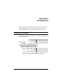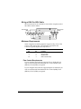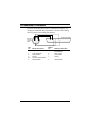
1
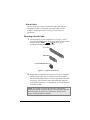
Courier V.Everything External Modem: Getting Started FINAL 4/96 p/n 1.024.492 1996 U.S. Robotics Access Corp. 8100 North McCormick Blvd. Skokie, IL 60076-2999 All Rights Reserved U.S. Robotics and the U.S. Robotics logo are registered trademarks of U.S. Robotics Access Corp. V.Fast Class and V.FC are trademarks of Rockwell International. Any trademarks, tradenames, service marks or service names owned or registered by any other company and used in this manual are the property of their respective companies. 1996 U.S. Robotics Access Corp. 8100 N. McCormick Blvd. Skokie, IL 60076-2999 USA Table of Contents About This Manual iii We Welcome Your Suggestions.............................................................iii Chapter 1 The Courier 1-1 Courier Controls, Displays, and Connectors.....................................1-3 Status Indicators ....................................................................................1-4 Features ...................................................................................................1-5 Chapter 2 Installing the Courier 2-1 What You Need......................................................................................2-1 Package Contents...................................................................................2-3 Installing the Courier ............................................................................2-4 Setting the DIP Switches.......................................................................2-4 Powering On the Courier .....................................................................2-6 Chapter 3 Communicating with the Courier 3-1 Windows 95............................................................................................3-1 Windows 3.x...........................................................................................3-5 DOS..........................................................................................................3-6 OS/2 ........................................................................................................3-6 Mac OS ....................................................................................................3-7 Windows NT ..........................................................................................3-7 UNIX/Linux/AIX ...............................................................................3-10 Mainframe OSs ....................................................................................3-10 Testing the Courier..............................................................................3-11 Chapter 4 Other Features 4-1 Volume Control .....................................................................................4-1 The Voice/Data Switch.........................................................................4-2 Getting Information About Calls ........................................................4-6 MI/MIC Operations..............................................................................4-7 Chapter 5 Setups for Common Windows Software Packages 5-1 Appendix A The Serial Port A-1 The EIA-232 Interface...........................................................................A-1 For Macintosh Computers...................................................................A-3 Appendix B Technical Specifications B-1 Standards Compatibility...................................................................... B-1 Appendix C Warranty and Notices C-1 Limited Warranty .................................................................................C-1 Notices....................................................................................................C-3 About This Manual This manual explains how to set up and start using your Courier V.Everything External Modem. Refer to the Command Reference manual, also included with the Courier, for detailed information about using advanced features. We Welcome Your Suggestions We’ve made every effort to provide you with useful, accurate information. If you have any comments or suggestions about these materials, please let us know. Voicemail: (847) 933-5200 Email: [email protected] Chapter 1 The Courier The Courier V.Everything External Modem makes any computer or terminal with an EIA/RS-232 serial port (or a Macintosh serial port) capable of exchanging data with modems or fax machines over standard, analog telephone lines at speeds of up to 33.6 Kbps. Using the Courier The most common uses of the Courier modem are for accessing the Internet or online services, accessing corporate networks remotely, calling bulletin board systems (BBSs), and for sending or receiving facsimiles or files. Using the Courier always requires some kind of communications software. The software required differs depending on what you’re trying to do. Accessing the Internet To access the Internet, you need to set up an account with an Internet service provider in your area. Often, Internet service providers supply you with the software you’ll need. In other cases, support for Internet access is built in to your computer’s operating system, as is the case with Windows 95. The software needed to access the Internet is called a TCP/IP protocol stack. Your TCP/IP protocol stack must provide a dialing application that is capable of sending data over a serial line using the Point-to-Point protocol (PPP) or the Serial Line Internet Protocol (SLIP). The Courier 1-1 Calling Online Services Each online service, such as America Online or CompuServe, provides its own customized communications software package. A couple of these packages are included with the Courier. These packages do the dialing and guide you through the steps of registration. Accessing Corporate Networks Remotely Dialing in to a remote network requires remote access software. When you dial in to a network, the software makes your remote computer appear to the network as locally attached. You can then use your network just as you would if you were there: send mail, print files, and access LAN drives. A remote access package is included with the Courier. Calling Bulletin Board Systems (BBSs) Calling a BBS requires communications software that does terminal emulation. The software should also support common, standard file transfer protocols, such as YMODEM and ZMODEM. A communications software package is included with the Courier. Sending Facsimiles or Files Most communications software packages support file transfers and many support fax operations. You can use fax-capable software to call fax machines or other fax modems and send facsimiles. 1-2 Courier V.Everything External Modem: Getting Started Courier Controls, Displays, and Connectors These figures show the controls, displays, and connectors on the Courier and indicate where to find more information about each. Voice/Data Switch SEE PAGE 4-2 HS AA CD NS RD SD DTR MR RTS CTS SYNC ARQ/ FAX Status LEDs VOICE/DATA COURIER V.EVERYTHING with V.34 Volume Control SEE PAGE 1-4 SEE PAGE 4-1 Figure 1-1. The Courier V.Everything Modem (Front). To Telephone To Wall Jack SEE PAGE 2-4 Power Switch SEE PAGE 2-4 To AC Power To Computer SEE PAGE 2-4 SEE PAGES 2-4 and A-1 SEE PAGE 2-6 Figure 1-2. The Courier V.Everything Modem (Back). The Courier 1-3 Status Indicators The Courier displays its status using 12 light-emitting diodes (LEDs) that are visible from the front. Table 1-1. The Courier's Status Indicators. HS On Off AA On Blinking Off CD On Off OH On Off RD Flashing Off SD Flashing Off TR On Off MR On Flashing Off RS On Off CS On Off High Speed 4800 bps or faster connection. Once on, remains on until reset. The Courier has not made a 4800 bps or faster connection since last reset. Auto Answer Status Auto-answer on. Incoming call detected. Auto-answer off. Carrier Detect Status Carrier detected from remote device, or carrier detect forced on (using DIP switch 6). Carrier not detected. Off Hook The Courier has control of the line. The Courier does not have control of the line. Received Data Status The Courier is sending data to your computer. Idle. Send Data Status The Courier is receiving data from your computer. Idle. Data Terminal Ready Status DTR signal received from your computer, or DTR is forced on (using DIP switch 1). DTR not detected. Modem Ready The Courier is powered on. The Courier is retraining with a remote device or is in test mode. The Courier is powered off. Request to Send Status RTS signal received from your computer. RTS signal not detected. Clear to Send Status The Courier is sending your computer the CTS signal. The Courier is not sending your computer the CTS signal. continued… 1-4 Courier V.Everything External Modem: Getting Started SYN On Blinking Off ARQ/FAX On Flashing Blinking Off Synchronous Status The Courier is in synchronous mode. Dial security is active. The Courier is not in synchronous mode/dial security not active. Error Correction/Fax Error correction is active. The Courier is retransmitting data to the remote modem. The Courier is in fax mode. Error correction not active/not retransmitting data/not in fax mode. Features 33.6 Kbps Connectivity The Courier contains software that enables 31.2 and 33.6 Kbps connection rates, as well as improves throughput at lower speeds. While line conditions may not always allow for 33.6 Kbps connections, the new software makes it more likely that your Courier will achieve and maintain 28.8 Kbps connections. It can add up to 4800 bps to the average V.34 connection rate. Selective Reject Selective Reject is an optional part of the ITU V.42 (LAPM) specification. This feature improves performance on noisy lines by reducing the amount of overhead incurred when the protocol must resend data due to errors. When selective reject is active, only the frame that contained the error is resent, instead of the frame plus all of the following unacknowledged frames. You can disable selective reject by changing a setting in S-Register 51 (see Appendix A, Alphabetic Command Summary, in the Courier Modems Command Reference manual). Attaining Speeds Above 28.8 Kbps V.34 connections at 21.6, 24.0, and 26.4 Kbps are common. To get connections of 28.8, 31.2, and 33.6 Kbps, line quality must be pristine end-to-end. In addition, 31.2 and 33.6 Kbps connection rates are possible only when the device to which you are The Courier 1-5 connecting also runs software that supports speeds above 28.8 Kbps. If you are curious about the role that line quality plays in attaining and maintaining high speed connections, and want to learn what you can do to improve connections, request the following document from our Fax on Demand service: Phone Line Quality and High Speed Connections. The Fax on Demand number is (800) 762-6163. V.Everything The Courier provides full support of the V.34 standard, V.Fast Class, V.32 terbo, and many other modulation schemes, spanning the range of speeds between 33.6 Kbps and 300 bps. We call this unique combination of abilities V.Everything. See the Compatibility section in Appendix B, Technical Specifications, for details. Flash ROM Upgradability Courier modems are software-upgradable using XMODEM file transfers, allowing you quick, easy access to updates of the Courier’s technology. See Chapter 17, Upgrading the Courier’s Software, in the Courier Modems Command Reference manual. Dial Security The Courier’s dial security functionality is part of its operating software, which allows you to control access at a modem-tomodem level instead of using software that runs on the host computer. With Dial Security, you can prevent unauthorized access to a system through the use of password prompting and dialback. Refer to Chapter 9, Dial Security, in the Courier Modems Command Reference manual. 1-6 Courier V.Everything External Modem: Getting Started Remote Configuration and Diagnostics You can remotely configure and test the Courier. If you are a network administrator supporting remote users, this feature can save you time and money. Refer to Chapter 8, Remote Access, in the Courier Modems Command Reference manual. Adaptive Speed Leveling (ASL) Couriers monitor line conditions while connected, and fall back to the next lower speed—for example, 19.2K, then 16.8K in V.32terbo mode—if conditions are poor. Couriers also detect improved line conditions and shift upward to the next higher speed. Transmit and receive channels adapt independently, each detecting and adjusting to line conditions. Calls to and from Modems and Fax Machines When used with fax-capable communications software, the Courier auto-detects and responds to calls from modems and Group III fax machines, using EIA-standard Class 1 or 2.0 fax software. Testing ITU-T V.54 loopback testing is available. The Courier can perform analog, digital, and remote digital loopback tests. See Chapter 15, Testing, in the Courier Modems Command Reference manual. Caller ID Support The Courier can interpret and display caller ID information. See the Caller ID section in Chapter 3, Dialing, Answering, and Hanging Up, in the Courier Modems Command Reference manual. Distinctive Ring Support The Courier can be set to recognize and respond to any of four distinctive ring patterns. See the Distinctive Ring section in Chapter 3, Dialing, Answering, and Hanging Up, in the Courier Modems Command Reference manual. The Courier 1-7 Carrier Loss Redial If you enable the carrier loss redial feature, the Courier will automatically redial the last number it dialed if carrier is lost (for example, if there is trouble on the line or if the remote modem hangs up). This feature is useful for dialed-line connections that operate unattended. See Chapter 3, Dialing, Answering, and Hanging Up, in the Courier Modems Command Reference manual. Plug and Play Support The software for the external Courier has been developed to support Plug and Play (as defined by the Plug and Play External COM Device Specification, Version 1.00). When you connect the Courier to a computer that uses a Plug and Play operating system, such as Windows 95, the computer will automatically detect and configure itself to the support the Courier. Synchronous Support The Courier can connect to synchronous serial ports to allow access to mini- and mainframe computers. See Chapter 12, Dedicated/Leased Line and Synchronous Applications, in the Courier Modems Command Reference. Dedicated- and Leased-Line Support The Courier does not need to be connected to the public switched telephone network. You can connect a standard telephone cable between the Courier and another modem and make connections without even dialing. You can also connect the Courier to a line that you lease from the telephone company. See Chapter 12, Dedicated/Leased Line and Synchronous Applications, in the Courier Modems Command Reference. 1-8 Courier V.Everything External Modem: Getting Started Chapter 2 Installing the Courier What You Need A Computer or Terminal with a Serial Port The Courier is compatible with any computer or terminal that provides a serial port with an EIA-232 interface. See Appendix A, The Serial Port, for details. For top performance, your serial port must support speeds of 115.2 Kbps. For IBM-compatible PCs, make sure your computer has a 16C550 UART. Check your computer’s documentation for details. An Analog Telephone Line The Courier requires a standard, analog telephone line. Do not connect the Courier to a digital telephone line. Digital lines are commonly used in office buildings and hotels. If you are unsure whether your line is analog or digital, ask a network administrator or your local telephone company. Communications Software You must configure and run a communications software package in order to make the Courier work. The Courier is shipped with a DOS/Windows communications software package. Installing the Courier 2-1 A Serial Cable Because there are a variety of connector types that different computers require, a serial cable is not provided with the Courier. See the next section, Choosing a Serial Cable, for guidelines. Choosing a Serial Cable 1 Check the back of your computer for a serial port. Serial ports may be labeled with the word COM or RS-232 or with symbols such as IOIOI, , or . Refer to your computer’s documentation to be sure. DB-25, Male DB-9, Male 8-pin Mini-DIN (Macintosh) Figure 2-1. Typical Serial Ports. 2 Depending on what kind of serial port is on your computer, obtain a serial cable with a connector that will fit (either a female DB-25, female DB-9, or a male 8-pin Macintosh serial connector). The Courier’s end of the serial cable must be a male DB-25 connector. For a Macintosh, you need a hardware handshaking cable. NOTE: If you plan to connect the Courier to a mainframe computer or use the Courier to dial in to a mainframe computer, refer to Chapter 12, Synchronous Applications, in the Courier Modems Command Reference manual. 2-2 Courier V.Everything External Modem: Getting Started Package Contents ♦ ♦ ♦ ♦ ♦ ♦ ♦ The Courier Power adapter Phone cable Quick reference card Customer support services card DOS/ Windows communications software package A Command Reference manual and this Getting Started manual Figure 2-2. Contents of the Courier Package. Installing the Courier 2-3 Installing the Courier 1 Connect the male DB-25 end of your serial cable to the Courier and the other end to a serial port on your computer. 2 If you are connecting the Courier to an IBM-compatible PC, note the number of the serial port to which you connect the Courier. If your serial ports are lettered instead of numbered, A is COM1 and B is COM2. 3 Connect one end of the phone cable to the wall jack and the other end to the Courier port labeled JACK. If you have a telephone that you’d like to connect to the Courier, plug its cable into the Courier port labeled PHONE. 4 Plug one end of the power adapter to the Courier and the other end to a standard AC outlet. 5 Switch your computer’s power on. Setting the DIP Switches The DIP switches are located on the bottom of the Courier. You will probably not need to change the DIP switch settings. DIP Switches Figure 2-3. Location of the DIP Switches. 2-4 Courier V.Everything External Modem: Getting Started Table 2-1. DIP Switch Settings. DIP Switch 1 Factory Setting OFF 2 For More Info1 Setting Effect OFF ON DTR normal Ignore DTR Ch 6 OFF OFF ON Verbal result codes Numeric result codes Ch 5 3 ON OFF ON Suppress result codes Display result codes Ch 5 4 OFF OFF ON Echo offline commands Don’t echo offline commands Ch 2 5 ON OFF ON Auto-answer Don’t auto-answer Ch 3 6 OFF OFF ON Normal Carrier Detect Carrier Detect always on Ch 6 7 OFF OFF ON Display all result codes Display result codes only when originating calls Ch 5 8 ON OFF ON Ignore AT commands (dumb mode) Act on AT commands (smart mode) Ch 1 9 OFF OFF ON Disconnect on +++ Don’t disconnect on +++ Ch 2 10 OFF OFF Load the configuration that is stored in non-volatile memory (NVRAM)* Load the &F0 configuration from read-only memory (ROM)* Ch 4 ON IMPORTANT: When you power ON or reset the Courier, the DIP switch settings override the settings you may have made previously using AT commands. If you change the DIP switch settings while the Courier is powered ON, you can avoid powering the Courier off to make the new settings take effect. Just send the Courier the ATZ command. 1 For more information, refer to the indicated chapter in the Courier Modems Command Reference. Installing the Courier 2-5 Powering On the Courier Flip the power switch at the back right corner of the Courier. Watch the LED indicators at the front. HS AA CD NS RD SD TR MR RS CS SYN ARQ/ FAX VOICE/DATA COURIER V.EVERYTHING with V.34 Figure 2-4. Normal Appearance of the Courier's LEDs When Not Attached to a Computer. HS AA CD NS RD SD TR MR RS CS SYN ARQ/ FAX VOICE/DATA COURIER V.EVERYTHING with V.34 Figure 2-5. Normal Appearance of the Courier's LEDs When Attached to a Computer and Ready to Receive Commands. 2-6 Courier V.Everything External Modem: Getting Started Chapter 3 Communicating with the Courier After you’ve connected the Courier to a serial port and powered the Courier on, you need to make sure that your computer can send commands to the Courier. Once you’re sure that your computer can communicate with the Courier, you’re ready to start making or taking calls! The methods of verifying communication with a modem vary depending on the operating system your computer uses. Windows 95 Windows 3.x Windows NT RAS DOS OS/2 Mac OS UNIX/AIX/Linux Mainframe OSs This chapter provides advice about how to get many popular operating systems to communicate with the Courier. The last section, Testing the Courier, explains how to verify that your Courier and software are working together correctly. Windows 95 The first time you start Windows 95 after you’ve installed the Courier, Windows 95 will auto-detect the Courier. Make sure the Courier is powered on when you start Windows 95. Windows 95 has built-in support for Couriers, but since the Courier has been updated since the release of Windows 95, you need to supply Windows 95 with an updated INF file so it can properly identify your Courier. The latest INF file is always available from our BBS and our ftp site. Communicating with the Courier 3-1 Getting the INF File 1 Power on your computer with the modem installed. As Windows 95 loads, it presents a New Hardware Found panel. Select Standard Modem. 2 Start a communications software package (such as HyperTerminal, which is included with Windows 95) and dial the U.S. Robotics BBS at (847) 982-5092. Go to File directories, then 5) U.S. Robotics Courier. Download the MDMUSRCR.INF file. Or, ftp://ftp.usr.com/SYS/PCB/dl05 and get MDMUSRCR.INF. Installing the INF File 1 Go to an MS-DOS Prompt: Microsoft® Windows 95 ©Copyright Microsoft Corp 1981-1995 c:\WINDOWS> 2 Change to the directory in which you put the INF file, for example, the TEMP directory. C:\WINDOWS>cd\temp Windows responds: C:\TEMP> 3 Enter the following command: C:\TEMP>copy mdmusrcr.inf \windows\inf Windows responds: 1 file(s) copied Be aware that the \inf directory is hidden, and even though it may not appear, it is there. 3-2 Courier V.Everything External Modem: Getting Started Making Windows 95 Auto-Detect Your Courier 1 Click Start | Settings | Control Panel and then double-click Modems. Remove the Standard Modem. 2 Then click Add. 3 At the Install New Modem panel, click Next. Windows 95 will auto-detect your Courier and install the appropriate support. Windows 95 Dial-Up Networking: Internet Access This section explains how to set up the Courier for accessing the Internet using Windows 95 Dial-Up Networking. You can also use Dial-Up Networking for accessing remote LANs. Make sure Dial-Up Networking is installed. 1 Click Start | Settings | Control Panel. 2 From the Control Panel, double-click on Network. If a Dial-Up Adapter is listed, go to step 5. If not, continue with step 3. 3 Go back to the Control Panel and double-click on Add/Remove Programs. 4 Click the Windows Setup tab. Then double-click on Communications. Click on Dial-Up Networking to check the box. Click OK, then OK. Insert your Windows 95 Setup diskette or CD-ROM when you are prompted, and Windows 95 will install Dial-Up Networking. Communicating with the Courier 3-3 Add Dial-Up TCP/IP Support. 5 Click Start | Settings | Control Panel. 6 From the Control Panel, double-click on Network. If TCP/IP -> Dial-Up Adapter is listed, go to step 8. If not, continue with step 7. 7 Select Add… | Protocol | Microsoft | TCP/IP | OK. Insert your Windows 95 Setup diskette or CD-ROM when you are prompted, and Windows 95 will install TCP/IP protocol support. Customize the TCP/IP Settings. 8 Click Start | Settings | Control Panel. 9 From the Control Panel, double-click on Network. 10 Select TCP/IP -> Dial-Up Adapter | Properties… Click on the DNS Configuration tab. Select Enable DNS. Type in your Host: and Domain: names, which are provided to you by your Internet service provider. Type your DNS server’s IP address or addresses (also provided by your Internet service provider) in the blank, and then click Add | OK | OK. 3-4 Courier V.Everything External Modem: Getting Started Set Up a Connection to Your Internet Service Provider. 11 Click Start | Programs | Accessories | Dial-Up Networking. 12 Double-click Make New Connection. Type a name for the connection, then click Next >. Type a phone number for the connection, then click Next >. You should see a message indicating that a new connection was created successfully. Click Finish. 13 From the Dial-Up Networking window, put the cursor over your new icon and click the right mouse button. Select Properties from the menu that appears. 14 Click Server Type…, and then deselect Log on to Network, NetBEUI, and IPX/SPX Compatible. Select OK, then OK. Double click on your new connection icon to connect! Windows 3.x Windows 3.x comes with a built-in communications software package, Windows Terminal. You can use Windows Terminal to test the Courier or you can install the communications software package that is included in the package with the Courier. Windows Terminal is in the Accessories group by default. Because Terminal only supports speeds up to 19200 bps, you will probably want to use a third-party communications software package, such as Quick Link II instead. For Quick Link II, see the section, Testing the Courier, on page 3-14. For other Windows software packages, see Chapter 5, Setups for Common Windows Software Packages. For instructions about how to set up your Windows communications software package, call our fax-on-demand service (at 800-762-6163 or 847-676-1598) or our BBS (at 847-9825092). Request document 10000 for a list of our technical support documents. Communicating with the Courier 3-5 DOS Because there is no communications software built in to DOS, you must install and run a third-party communications software package in order to operate the Courier. The Quick Link II diskette, which is included in the package with the Courier, contains a DOS version of the software as well as a Windows version. You must choose the COM port to which the Courier is attached in whatever communications software package you are using. For instructions about how to set up your DOS communications software package, call our fax-on-demand service (at 800-7626163 or 847-676-1598) or our BBS (at 847-982-5092). Request document 10000 for a list of our technical support documents. OS/2 To get the best performance, you should replace the standard OS/2 serial port drivers COM.SYS and VCOM.SYS with SIO.SYS and VSIO.SYS. You can get these enhanced drivers from our BBS at 847-982-5092. Check file area 18, OS/2 Support, Utilities, etc for SIO153.ZIP. For help with OS/2 Warp installations, download the file WARPIN.ZIP from BBS file area 18, OS/2 Support, Utilities, etc. For instructions about how to set up your OS/2 communications software package, call our fax-on-demand service (at 800-7626163 or 847-676-1598) or our BBS (at 847-982-5092). Request document 10000 for a list of our technical support documents. 3-6 Courier V.Everything External Modem: Getting Started Mac OS Be sure you’re using a hardware handshaking cable to connect the Courier to the Macintosh. Also, if you won’t be using AppleTalk Remote Access (ARA), then set AppleTalk to Inactive (in Chooser). Otherwise ARA may interfere with your communcations software. As a general rule, set DIP switches 1, 3, 5, and 8 ON, and use AT&F1 as your modem initialization string. For instructions about how to set up your Macintosh communications software package, call our fax-on-demand service (at 800-762-6163 or 847-676-1598) and request document 10000 for a list of available documents. Or, call our Macintosh BBS (at 847-676-1598). Windows NT As a Client If you want only to dial out using the Courier, Windows NT works very much like Windows 3.x. Windows NT ships with a built-in Terminal program that can support speeds of up to 115.2 Kbps. Additionally, Windows NT includes a Remote Access Dialer, but it is not installed by default. You can install Quick Link II in Windows NT but you may experience problems with fax operations. As a Server Here’s how to set up Windows NT Remote Access Service (RAS) to recognize the Courier. First, you must install RAS, which is included with Windows NT but is not installed by default. Communicating with the Courier 3-7 Start Windows Terminal to verify that NT can communicate with the Courier. Select the COM port to which the Courier is connected. You should be able to send AT <Enter> and get an OK response. From the Control Panel, double-click Network. The Network Settings window appears. Scroll down the list of Installed Network Software and select Remote Access Service. Click Configure… The Remote Access Setup windows appears. Click Add… 3-8 Courier V.Everything External Modem: Getting Started Select the port to which the Courier is connected. When you click OK, Remote Access setup asks you if you would like it to try to detect the modem connected to the port. Click Cancel to select the Courier from a list. Select US Robotics Courier V.34, and then click OK and exit from Network setup. When you’re prompted to restart NT, click Don’t Restart Now. Then, from Program Manager, click File | Shutdown. When NT shuts down, power your computer off and then on again. Now RAS knows about the serial port and the Courier that is attached. Next, you need to set up user accounts and access privileges; those tasks are beyond the scope of this manual. Communicating with the Courier 3-9 UNIX/Linux/AIX If the Courier will be answering, set DIP switch 3 OFF; 4 and 8 ON. Linux has a built-in communications software package called minicom. By default, minicom is located in the usr/bin directory. For instructions about how to set up your UNIX, Linux, or AIX communications software package, call our fax-on-demand service (at 800-762-6163 or 847-676-1598) or our BBS (at 847-9825092). Request document 10000 for a list of our technical support documents. Mainframe OSs Refer to Chapter 12, Synchronous Applications, in the Courier Modems Command Reference manual. 3-10 Courier V.Everything External Modem: Getting Started Testing the Courier Use any communications software package for this test. Quick Link II Fax is used as an example. Quick Link II Fax 1 Install and then start Quick Link. 2 Click Setup | Line Settings… Make the following settings. If you are using a computer with a serial port that cannot support high speeds, choose 19200. Then click OK. 3 Click Setup | Modem Setup… Select the Comm. Port to which the Courier is attached. Click OK. 4 In the terminal window, type AT <Enter>. The Courier should respond OK. 5 Dial the U.S. Robotics BBS at (847) 982-5092. For example, ATDT18479825092 <Enter> dials the U.S. Robotics BBS as a long-distance call. Communicating with the Courier 3-11 NOTE: If you need to dial 9 to get an outside line, dial as in this example: ATDT9,18479825092 <Enter>. If you want to disable call waiting for this call, in most areas, dial *70 before you dial the phone number, for example, ATDT*70,18479825092 <Enter>. The following screens are what you should see when you dial the BBS. atdt9825092 CONNECT 31200/ARQ/V34/LAPM/V42BIS CONNECT 31200/ARQ/V34/LAPM/V42BIS CONNECT 115200 / 02-27-96 (12:52:21) (Error Correcting Modem Detected) USR Support BBS - ComServer 486 PCBoard (R) v15.22/100 - Node 11 Testing your system capability... Do you want graphics (Enter)=yes? ( Figure 3-1. Connecting... Figure 3-2. Success! 3-12 Courier V.Everything External Modem: Getting Started ) Chapter 4 Other Features This chapter explains how to use features specific to the Courier V.Everything External Modem, including the volume control, the Voice/Data switch, and MI/MIC operations. Voice/Data Switch HS AA CD NS RD SD DTR MR RTS CTS SYNC ARQ/ FAX VOICE/DATA COURIER V.EVERYTHING with V.34 Volume Control Volume Control The volume control is located under the right front of the Courier. Slide the control toward the front of the Courier to increase the volume. Slide the control toward the back of the Courier to decrease the volume. Use the ATMn command to control when the speaker sounds. M1 is the default. Mn Control when the speaker sounds. M0 The speaker is always off. M1 The speaker is on until the call is negotiated. M2 The speaker is always on. M3 The speaker turns on after the last digit is dialed and stays on until the call is negotiated. Example: ATM1 <Enter>. Other Features 4-1 The Voice/Data Switch The Voice/Data switch allows you to alternate voice and data over the same connection. You call the remote user by telephone, then you each press the Voice/Data switch on the Courier. After you’re finished sending and receiving files, press the Voice/Data switch to return to voice. You can accomplish the same function by sending AT commands, and you can also assign a different function to the Voice/Data switch if you don’t plan to use it for alternating voice and data. Changing back to voice after the modems connect requires that both modems have handset exclusion. Handset exclusion means that when the modem is using the phone line, the modem automatically disconnects the phone (handset). If you keep the handset off hook, once you hang up the modem, the handset takes over the phone line and you can use voice communications again. If the remote user does not have handset exclusion, you may not be able to switch back to voice mode successfully once you have switched to Data mode. If the remote user does not have a Voice/Data switch, he or she can follow the instructions for using the appropriate AT command. See the next section for details. Using the Voice/Data SwitchS32=1, S32=2 Either user can start the call, but you need to decide up front which modem will originate and which will answer. 1 Send the modem that will originate ATS32=1 <Enter> Sending ATS32=1 tells the Courier to go on line and send ATD <Enter> when you press the Voice/Data switch. 2 4-2 Send the modem that will answer ATS32=2 <Enter> Courier V.Everything External Modem: Getting Started Sending ATS32=2 tells the Courier to go on line and send ATA <Enter> when you press the Voice/Data switch. NOTE: If you’ve stored a command string (using &ZC=s), the Courier will default to S32=9, which executes the stored command string when you push the Voice/Data switch. 3 Call the remote user (make a voice call) or have them call you. You must the phone that is attached to the Courier’s PHONE port. 4 When you’re ready for the modems to connect, press the Voice/Data switch of the “originating” modem (the one that set S32=1). The handset goes dead. Do not hang up the phone. Immediately afterward, press the Voice/Data switch of the “answering” modem (the one that set S32=2). The modems go through the normal negotiation process. If the answering modem has handset exclusion, the answering user should not hang up the phone either. If the remote modem doesn't have handset exclusion, you can try to switch back to voice later. Or, you both can hang up your phones as soon as the modems go off hook. Using CommandsATD, ATA If your Voice/Data switch is set for a function other than Voice/Data operations and you don't wish to change it, use AT commands. 1 Make a voice call to the remote user (or have the remote user call you). You must both use telephones that are connected to the PHONE port of your modems. Other Features 4-3 2 If you are to originate the connection, type the following command: ATD <Enter> NOTE: Be sure the modem is not set to X2, X4, X6 or X7, or it will return the NO DIAL TONE result code and hang up. 3 The remote user should type the answer command: ATA <Enter> 4 If the remote modem also has handset exclusion, leave both phones off hook in case you wish to switch back again to voice after your data transfer. If the remote modem doesn't have handset exclusion, switching back to voice may not be successful. If you don't want to switch back to voice later, hang up both phones as soon as the modems go off hook. Changing the Function of the Voice/Data Switch Use Register S32 to set the voice/data switch for the function you desire. The default is S32=1pressing the switch forces the modem off hook in Originate mode. Holding the switch in when you power on the modem causes it to perform a power-on self-test. NOTE: Some of the applications listed below require preconfiguration. Review the Chapter (from Table 4-1) in the Courier Modems Command Reference before assigning the Voice/Data switch function. 4-4 Courier V.Everything External Modem: Getting Started Table 4-1. Voice/Data Switch Commands. S32 Value 0 1 2 3 4 5 6 7 8 9* Voice/Data Switch Function Disabled Voice/DataOriginate Mode Voice/DataAnswer Mode Redial Last Number Dial Number Stored at position 0 Auto Answer On/Off Toggle Reset Modem Initiate Remote Digital Loopback Busy Out the Phone Line Toggle Execute Stored Command Related Command _ ATD (Chapter 3) ATA (Chapter 3) ATDL (Chapter 3) ATDS0 (Chapter 3) ATS0=0 or 1 (Chapter 3) ATZ (Chapter 4) AT&T6, S16=8 (Chapter 15) _ AT&ZC=s (Chapter 4) * The modem is shipped from the factory set at S32=9. If a command string has been stored (&ZC=s), the Courier sends the stored command string when you push the Voice/Data switch. If no command string is stored, the Courier still reports that S32=9, but actually behaves as if it is set to S32=1, Originate mode. You can program the voice/data switch to execute a stored command string when pressed. The following example assigns a command string that displays the link diagnostics screen when you press the voice/data switch. AT&ZC=I6 <Enter> Set the voice/data switch function to execute stored command string by setting Register S32 to 9 with the following command: ATS32=9 <Enter> Note that you can reset the voice/data switch at any time to one of the other available functions. Additionally, you can overwrite the stored command string with a new one at any time. Once you've stored your command string and set Register S32, press the Voice/Data switch whenever you want the Courier to send the command string. Other Features 4-5 Getting Information About Calls Here are the commands that provide detailed information about your current settings and current and last calls. To get call-in-progress data and current settings while you are on line, set DIP switch 9 OFF and then send ATZ <Enter> (or power the Courier off and then on). Alternatively, you can send ATS14.0=0 <Enter>, but be aware that the DIP switch setting will override your setting at power on or reset (even if you add &W to write the command to NVRAM). Once you’ve set DIP switch 9 or sent ATS14.0=0 <Enter>, you can type the following command to get to online command mode, and the Courier will not hang up: +++ To return on line, type: ATO <Enter> Current Settings Current settings Data or fax mode ATI4 AT+FCLASS? 0=Data 1=Class 1 fax 2.0=Class 2.0 fax Call in Progress Speed Duration Modulation Error control protocol Compression type Data or fax mode 4-6 ATI6 — Speed ATI6 — Current Call ATI11 — Modulation ATI6 — Protocol ATI6 — Compression AT+FCLASS? 0=Data 1=Class 1 fax 2.0=Class 2.0 fax Courier V.Everything External Modem: Getting Started Last Call Last-dialed number Disconnect reason Speed Duration Modulation Error control protocol Compression type ATI4 — Last Dialed # ATI6 — Disconnect Reason is ATI6 — Speed ATI6 — Last Call ATI11 — Modulation ATI6 — Protocol ATI6 — Compression MI/MIC Operations Couriers are shipped with MI/MIC disabled, that is, for normal use. Mode Indicate/Mode Indicate Common (MI/MIC) closure is required for some applications where existing hardware, such as a PBX, does the dialing. For these applications, the Courier must power up in Originate mode. Then the Courier goes on line and accepts data when it connects with the number dialed by the system equipment. Once you've set Register S34, have the system force the modem off hook by closing the MI/MIC leads in the phone line connector. Setting the MI/MIC Jumpers 1 2 3 Send ATS34.5=1&W <Enter>. Power off the Courier and disconnect all of its cables. Turn the Courier upside down. Remove the two square vinyl feet and put them aside. 4 Remove the two Phillips screws located in the wells beneath the vinyl feet. 5 6 Pry off the plastic volume slide-switch cover. Raise the back end of the case bottom and lift it away. Other Features 4-7 7 Remove the modem (printed circuit board), carefully easing the voice/data switch out of its opening in the front panel. 8 Locate jumpers J4 and J6. J4 J6 MI/MIC Jumpers Figure 4-1. Location of the MI/MIC Jumpers. 9 Set the jumpers as shown: To From J4 J6 10 Replace the modem and reconnect the J4 J6 cables. CAUTION: When you power on the modem there will be potentially hazardous voltage, particularly near the phone jacks. Do not touch the board when the power is on. 11 Power on the modem. Check to see that the Off Hook (OH) status light goes on. If you dialed a number, listen for an answer tone from the remote modem. Then drop the DTR signal. The modem should go on hook and the OH status light should go off. 4-8 Courier V.Everything External Modem: Getting Started 12 When you are sure the equipment is working correctly, reassemble the Courier. Troubleshooting If the Courier does not respond to MI/MIC closure, or if the Courier fails to go back on hook when the computer or terminal drops the Data Terminal Ready (DTR) signal, your phone equipment probably reverses MI/MIC polarity. You can solve this problem by reversing the modem's MI/MIC wiring. Do this by resetting the two jumpers on the printed circuit board. Follow the steps from the previous section. This time, set the jumpers as follows: From To J4 J6 J4 J6 If you still have difficulty, there may be a problem with the phone cable or with your hardware. Other Features 4-9 Chapter 5 Setups for Common Windows Software Packages If you are running one of the following software packages, follow the steps given to configure it for use with the Courier. America Online v2.0 NetManage Chameleon v4.5 pcAnywhere v2.0 for Windows ProComm Plus v2.0 for Windows Prodigy Trumpet Winsock WinCIM (for CompuServe) WinFax Pro 4.0 These instructions are valid as of the printing of this manual and may not apply to future releases of the software packages. If you need further help, or help with a software package that is not listed here, try our fax-on-demand service (at 800-762-6163 or 847-676-1598) or our BBS (at 847-982-5092). Request document 10000 for a list of our technical support documents. America Online 2.0 1 From the America Online - Welcome window, choose Setup. 2 From the Network & Modem Setup window, select Setup Modem. 3 From the Modem Selection and Customization window, select the COM port that the Courier is using, and choose USRobotics Courier HST Dual Std/PC FAX w/ASL (v2.0) as your modem. Then select Edit Commands. Setups for Common Windows Software Packages 5-1 4 The following window will appear. Change the Setup Modem String to match: 5 Select OK, then OK, then OK. NetManage Chameleon 4.5 You should know in advance which Internet service provider (for example, PSINet or NETCOM) you will be using. NetManage provides a number of configuration templates for many popular Internet service providers. The settings recommended here are the Courier-specific ones only. 1 Click Setup | Communications | Port. Two settings will be specific to your setup: Baud Rate: 115200 bps is recommended, but only if you have a 16550 UART. The UART is a computer chip that controls the transmission and reception of signals through your computer’s serial port. Check your computer’s manual to be sure - slower UARTs, like 16450 or 8250, will limit speeds to 19200 bps. Connector: Select the COM port to which the Courier is attached. 5-2 Courier V.Everything External Modem: Getting Started 2 Click Setup | Communications | Modem. Select U.S. Robotics Courier Dual Standard. Setups for Common Windows Software Packages 5-3 pcAnywhere 2.0 for Windows 5-4 1 From the Smart Setup window, go to the Your Modem area and select USRobotics Courier HST Dual Standard. 2 Select the serial port and the protocol running on the network into which you’ll be dialing, and then select OK. Courier V.Everything External Modem: Getting Started ProComm Plus 2.0 for Windows 1 Double-click on the PROCOMM PLUS icon. 2 Select Setup, and then Setup.... 3 Select Data Modem/Connection, and then Connection Setup as shown in the following window: 4 Select Install New Modem or Connection. Under AutoDetect, select Start Search. Setups for Common Windows Software Packages 5-5 5 After the search is complete, go to the Modems list and select US Robotics Dual Standard 28800, and then select OK. Prodigy 5-6 1 Start Prodigy. 2 From the Prodigy SIGN-ON window, select Comm Options Setup. 3 From the Set Up window, select a Modem Speed of 9600 bps and select the Communications Port that the Courier is using; then select OK. Courier V.Everything External Modem: Getting Started Trumpet Winsock 1 From Windows, double-click the Trumpet Winsock icon. Select Dialler, and then Edit Scripts. 2 Open the LOGIN.CMD file. Change these lines: output AT&F1\13 input 10 OK\n output atdt<phone number to dial> 3 Exit and save the changes you made. 4 From File | Setup, under SLIP Port, enter the COM port number that the Courier is using, its Baud Rate, and check Hardware Handshake. You’re now ready to call your Internet service provider. Select Dialler | Login. Win CIM (CompuServe) 1 From Windows Main, double-click on Control Panel. From Control Panel, double-click on Ports. Set the COM port that the Courier is using to 19200 baud rate and Hardware flow control. 2 Start the WinCIM program, and select Special and then Session Settings. Make sure that you choose the COM port that the Courier is using and set the baud rate to 19200. 3 From the Special pull-down menu, select Modem Control Strings. Your modem type should be Current and Initialize should show this string: AT&F&B1&H1&R2&A3&K3X4^M Reset should show &F, Connect should show CONNECT, and Suffix should show ^M. Setups for Common Windows Software Packages 5-7 WinFax PRO 4.0 5-8 1 During installation, you are asked the following question: Do you want Setup to test COM ports for a fax device? Select Yes. 2 When the following screen appears, choose as the Model U. S. Robotics, Inc Courier Dual Standard FAX, and then select Continue. Courier V.Everything External Modem: Getting Started Appendix A The Serial Port Most computers provide a DB-25 or DB-9 port that conforms to the EIA-232 standard. If you are connecting the Courier to a Macintosh computer, see the section For Macintosh Computers. The EIA-232 Interface The Courier’s serial port is factory set to signal according to the EIA-232 standard: DB-25 Connector (Female) Figure A-1. Signals at the Courier's Serial Port. The Serial Port A-1 Wiring a DB-25 to DB-9 Cable DB-9 connectors for PCs should be wired at the computer end of the cable as shown below. DB-9 Connector (Female) DB-25 Connector (Male) Minimum Requirements Some computer/terminal equipment supports only a few of the Courier’s EIA-232 signals. The minimum required for the Courier to operate asynchronously follows: DB-25 Pin 2 3 7 20 DB-9 Pin 3 2 5 4 Function Transmitted Data Received Data Signal Ground Data Terminal Ready Flow Control Requirements If your computer and software support Clear to Send and you wish to use Transmit Data hardware flow control (&H1), Pin 5 (DB-25) or Pin 8 (DB-9) is required. If your computer and software support Request to Send and you wish to use Received Data hardware flow control (&R2), Pin 4 (DB-25) or Pin 7 (DB-9) is required. A-2 Courier V.Everything External Modem: Getting Started For Macintosh Computers If you’re connecting the Courier to a Macintosh computer, we strongly recommend that you purchase a Hardware Handshaking cable to get the most reliable performance. DB-25 Connector (Male) Macintosh 8-pin DIN Connector (Male) 8 3 4 1 2 3 5 4 5 7 20 2 Mac Pin 1 Mac Pin Description Output Handshake 2 3 4 4,8 5 Input Handshake Transmit Data Ground Ground to Received Data Received Data - Modem Pin 4,20 5 2 7 Modem Pin Description Request to Send and Data Terminal Ready Clear to Send Transmit Data Ground 3 Received Data The Serial Port A-3 Appendix B Technical Specifications Standards Compatibility The Courier uses multiple standard data communications protocols and is also compatible with many nonstandard schemes. NOTE: The International Telecommunication Union (ITU-T) was formerly the International Telegraph and Telephone Consultative Committee (CCITT). Modulation ITU-T V.34 33.6/31.2/28.8/26.4/24/21.6/19.2/16.8/14.4/12 Kbps; 9600/7200/4800 bps asynchronous Trellis Coded Modulation (TCM) V.FC 28.8/26.4/24/21.6/19.2/16.8/14.4 Kbps asynchronous Trellis Coded Modulation (TCM) V.32terbo 21.6/19.2/16.8/14.4/12 Kbps; 9600/7200 bps asynchronous Trellis Coded Modulation (TCM); 4800 bps asynchronous Quadrature Amplitude Modulation (QAM) HST 16.8/14.4/12 Kbps; 9600/7200 bps asynchronous, asymmetrical, 450 bps back channel with automatic handshake adjustment to 300 bps Trellis Coded Modulation (TCM) and Quadrature Amplitude Modulation (QAM); 4800 bps asynchronous, asymmetrical, 450 bps back channel with automatic Technical Specifications B-1 handshake adjustment to 300 bps Quadrature Amplitude Modulation (QAM). ITU-T V.32bis 14.4/12 Kbps; 9600/7200 bps asynchronous Trellis Coded Modulation (TCM); 4800 bps asynchronous Quadrature Amplitude Modulation (QAM) ITU-T V.32 9600 bps asynchronous, Trellis Coded Modulation (TCM); 4800 bps asynchronous, Quadrature Amplitude Modulation (QAM) ITU-T V.22bis 2400 bps asynchronous, Quadrature Amplitude Modulation (QAM) Bell 212A 1200 bps (also V.22) asynchronous, Differential Phase Shift Keying (DPSK) ITU-T V.23 1200 bps asymmetrical with 75 bps back channel with Frequency Shift Keying (FSK), used by some U.K. and European phone systems. Bell 103 300 bps (ITU-T V.21 optional) asynchronous, Frequency Shift Keying (FSK) Error Control, Data Compression, Testing, and Dialing ITU-T V.42 LAPM error control, 1200 bps and higher MNP Levels 2, 3 and 4 error control, level 5 data compression, 1200 bps and higher HST Asymmetrical mode, at 16.8/14.4/12 Kbps; 9600/ 7200/4800 bps, 450/300 bps back channel ITU-T V.42bis Data compression, 1200 bps and higher ITU-T V.54 Digital and remote digital loopback testing ITU-T V.25bis Dialing and answering method for automatic calling and/or answering equipment. Fax The Courier provides Group III-compatibility when controlled by Class 1 or Class 2.0 fax software. In addition, the Courier adheres to the following standards: TIA/EIA-578 B-2 Service Class 1 Asynchronous Facsimile DCE Control Standard Courier V.Everything External Modem: Getting Started TIA/EIA-592 Service Class 2.0 Asynchronous Facsimile DCE Control Standard ITU-T V.17 14.4/12 Kbps ITU-T V.29 9600/7200 bps ITU-T V.27ter 4800/2400 bps ITU-T V.21 300 bps Additional Specifications Supported serial port rates 115200, 57600, 38400, 19200, 9600, 4800, 2400, 1200, 300 bps Adaptive Speed Leveling (ASL) 21600, 19200, 16800, 14400, 12000, 9600, 7200, 4800 bps Serial port connector DB-25 Serial interfaces EIA RS-232, supports Macintosh serial ports Communications channel Full- or half-duplex on 2-wire phone lines; demand-driven high-speed turnaround in HST mode; symmetrical speeds in V.32 bis Data format Binary, serial; defaults to 8-bit word length, no parity, and 1 stop bit. Word Parity Stop Length (1 Bit) Bits 7 Even, Odd, 1 Mark, Space 7 None 2 8 None 1 Flow Control Buffers Variable sizes Command Buffer 56 characters, excluding the AT prefix, Carriage Return and spaces Technical Specifications B-3 B-4 Test Options Remote digital loopback, digital loopback, test pattern, and dial test Failed Call Timeout 60 second default, programmable 2-255 sec Answer Tone Timeout 60 seconds Answer Tone Detector 2080-2120 Hz Loss of Carrier (Disconnect Timer) 0.7 second default, programmable 0.2-25.5 sec. Equalization Adaptive Receive Sensitivity - 43 dBm + 2 dBm Transmit Level - 9 dBm maximum Transmitter Frequency Tolerance .01% Certification FCC Part 15, Class B Domestic; IC (Canada) CS-03, UL listed Ringer Equivalence 0.4b Courier V.Everything External Modem: Getting Started Appendix C Warranty and Notices Limited Warranty U.S. Robotics Access Corp. warrants to the original consumer or other end user purchaser that this product is free from defects in materials or workmanship for a period of five years from the date of purchase. During the warranty period, and upon proof of purchase, the product will be repaired or replaced (with the same or similar model) at our option, without charge for either parts or labor. This warranty shall not apply if the product is modified, tampered with, misused, or subjected to abnormal working conditions. REPAIR OR REPLACEMENT AS PROVIDED UNDER THIS WARRANTY IS THE EXCLUSIVE REMEDY OF THE PURCHASER. THIS WARRANTY IS IN LIEU OF ALL OTHER WARRANTIES, EXPRESS OR IMPLIED, INCLUDING ANY IMPLIED WARRANTY OF MERCHANTABILITY OR FITNESS FOR A PARTICULAR USE OR PURPOSE, AND U.S. ROBOTICS SHALL IN NO EVENT BE LIABLE TO PURCHASER FOR INDIRECT OR CONSEQUENTIAL DAMAGES OF ANY KIND OR CHARACTER. Some states do not allow the exclusion or limitation of incidental or consequential damages or allow limitations on how long an implied warranty lasts, so the above limitations or exclusion may not apply to you. This warranty gives you specific legal rights. You may also have other rights that vary from state to state. Warranty and Notices C-1 Should you encounter problems in operating this device, first follow the instructions in Chapter 16, Troubleshooting, of the Courier Modems Command Reference manual. The chapter contains solutions to operating problems as well as procedures to follow if there is an apparent Courier malfunction. Service/Support To obtain service under this warranty, contact U.S. Robotics Corporate/Systems Support as described below. Be sure to have the product’s serial number handy if you call, or send copies if you are contacting us by mail. Contacting U.S. Robotics Check the Corporate/Systems Customer Support card that came with your Courier for information about how to contact us. If the support representative determines that you should send your equipment to USR for service, you will be given a Service Repair Order (SRO) number to help us keep track of your warranty request. Once you have received your SRO number, take or mail the product, postage prepaid, to U.S. Robotics at the address on page 16-8 in the Courier Modems Command Reference. Include proof of the date of purchase. IMPORTANT: If you ship your unit, pack it securely, be sure your SRO number is visible on the outside of the package, and ship it charges prepaid and insured. C-2 Courier V.Everything External Modem: Getting Started Notices FCC Registration FCC15: CJE-0263 FCC 68: CJEUSA-73130-FA-E Connecting to the Telephone Company’s Lines The telephone company may request the telephone number(s) to which the Courier is connected and the FCC information printed above. If the Courier is malfunctioning, it may affect the telephone lines. In this case, disconnect the Courier until the source of the difficulty is traced. FCC Notice: Radio and Television Interference This equipment has been tested and found to comply with the limits for a Class B digital device, pursuant to Part 15 of the FCC Rules. These limits are designed to provide reasonable protection against harmful interference in a residential installation. This equipment generates, uses, and can radiate radio frequency energy and, if not installed and used in accordance with the instructions, may cause harmful interference to radio communications. However, there is no guarantee that interference will not occur in a particular installation. If this equipment does cause harmful interference to radio or television reception, which can be determined by turning the equipment off and on, the user is encouraged to try to correct the interference by one or more of the following measures: -- Reorient or relocate the receiving antenna. -- Increase the separation between the equipment and receiver. -- Connect the equipment into an outlet on a circuit different from that to which the receiver is connected. -- Consult the dealer or an experienced radio/TV technician for help. Warranty and Notices C-3 IC (Industry Canada) This digital apparatus does not exceed the Class B limits for radio noise emissions from digital apparatus set out in the radio interference regulations of Industry Canada (formerly Canadian Department of Communications). Le présent appareil numérique n'émet pas de bruits radio-électriques dépassant les limites applicables aux appareils numériques de la classe B prescrites dans le Règlement sur le brouillage radioélectrique édicté par Industrie Canada (antérieurement le ministère des Communications du Canada). The Industry Canada (formerly DOC) label identifies certified equipment. This certification means that the equipment meets certain telecommunications network protective, operational, and safety requirements. The department does not guarantee the equipment will operate to a user's satisfaction. Before installing this equipment, make sure you are permitted to connect it to the facilities of the local telecommunications company. You must also install the equipment using an acceptable method of connection. In some cases, you may also extend the company's inside wiring for single line individual service by means of a certified connector assembly (telephone extension cord). You should be aware, however, that compliance with the above conditions may not prevent degradation of service in some situations. Repairs to certified equipment should be made by an authorized Canadian maintenance facility designated by the supplier. Any repairs or alterations made by a user to this equipment, or equipment malfunctions, may give the telecommunications company cause to request the user to disconnect the equipment. C-4 Courier V.Everything External Modem: Getting Started For your own protection, make sure that the electrical ground connections of the power utility, telephone lines, and internal metallic water pipe system, if present, are connected together. This precaution may be particularly important in rural areas. WARNING: Do not attempt to make such connections yourself; contact the appropriate electric inspection authority or electrician. Warranty and Notices C-5 Index 3 33.6 Kbps · 1-5 A AA light · 1-4 access Internet · 1-1 remote · 1-2 Adaptive Speed Leveling (ASL) · 1-7, B-3 AIX · 3-10 alternating voice and data · 4-3 America Online · 5-1 AppleTalk Remote Access (ARA) · 3-7 ARQ/FAX light · 1-5 B Bulletin Board System (BBS) · 1-2 C cable DB-25 to DB-9 · A-2 hardware handshaking · 2-2, A-3 serial · 2-2 caller ID feature · 1-7 calls, getting information about · 4-6 carrier loss redial feature · 1-8 CD light · 1-4 Chameleon · 5-2 COM port · 2-1 communications software · 2-1 compression protocols · B-2 CompuServe · 5-7 contents of package · 2-3 CS light · 1-4 D data compression protocols · B-2 DB-25 connectorError! Bookmark not defined. · A-2 DB-9 connector · A-2 dedicated-line support · 1-8 dialer · 1-1 dialing protocols · B-2 Dial-Up Networking · 3-3 digital telephone lines · 2-1 DIP switches, setting · 2-4 distinctive ring feature · 1-7 DNS configuration · 3-4 DOS · 3-6 E EIA-232 · 2-1, A-1 error control protocols · B-2 Index I–1 F M fax features · 1-7 protocols · B-2 sending · 1-2 FCC notice · C-3 Flash memory · 1-6 flow control · A-2 Mac OS · 3-7 Macintosh computers cabling · A-3 communications · 3-7 minicom · 3-10 MR light · 1-4 N H hardware handshaking cable · 2-2, A-3 high speeds, attaining · 1-5 HS light · 1-4 HyperTerminal · 3-2 I IC notices · C-4 indicators, appearance at power-on · 2-6 INF file for Windows 95 · 3-1 installation procedure · 2-4 Internet access · 1-1 L last call information · 4-7 leased-line support · 1-8 LEDs · 1-3 appearance at power-on · 2-6 meanings of · 1-4 lights appearance at power-on · 2-6 status · 1-4 line quality · 1-6 Linux · 3-10 I–2 NetManage Chameleon · 5-2 notices · C-3 O OH light · 1-4 online command mode · 4-6 online services · 1-2 OS/2 · 3-6 P package contents · 2-3 pcAnywhere · 5-4 Plug and Play · 1-8 Point-to-Point Protocol (PPP) · 1-1 port, serial · 2-1 ProComm Plus · 5-5 Prodigy · 5-6 protocols · B-1 R RD light · 1-4 redial, carrier loss · 1-8 Remote Access Dialer for Windows NT · 3-7 Remote Access Service for Windows NT · 3-7 Courier V.Everything External Modem: Getting Started remote configuration of the Courier · 1-7 RS light · 1-4 RS-232 · See EIA-232 S SD light · 1-4 security features · 1-6 selective reject · 1-5 serial cable · 2-2 Serial Line Internet Protocol (SLIP) · 1-1 serial port · 2-1 settings, current · 4-6 software, communications · 2-1 speaker, controlling the · 4-1 standards compatibility · B-1 status indicators · 1-3 switches, setting · 2-4 SYN light · 1-5 synchronous applications · 1-8, 3-10 T TCP/IP · 1-1, 3-4 technical specifications B-1 testing the Courier · 1-7, 3-11 TR light · 1-4 Trumpet Winsock · 5-7 V V. protocols · B-1 V.34 · 1-5, B-1 V.Everything, defined · 1-6 verifying operation · 3-11 Voice/Data switch · 1-3, 4-2 volume control · 1-3, 4-1 W Warp · 3-6 warranty · C-1 Win CIM · 5-7 Windows 3.1 · 3-5 3.11 · 3-5 95 · 3-1 for Workgroups · 3-5 NT · 3-7 Terminal · 3-5 WinFax PRO · 5-8 Winsock · 5-7 Y YMODEM file transfer protocol · 1-2 U Z U.S. Robotics BBS · 3-11 contacting the writers · iv UART · 2-1 UNIX · 3-10 ZMODEM file transfer protocol · 1-2 Index I–3 I–2 Courier V.Everything External Modem: Getting Started