1
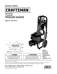
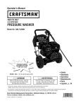
Operator's Manual
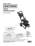
3800 PSI*
4.0 GPIVi
PRESSUREWASHER
Model No. 580.752382
HOURS: IVlon.- Fri. 8 a.m. to 5 p.m. (CT)
WARNING
Before using this product, read this
manual and follow all Safety Rules
and Operating Instructions.
ADVERTENCIA
Antes de utilizar el producto, lea este
manual y siga todas las Reglas de
Seguridad e Instrucciones de Uso.
• Safety
• Assembly
• Operation
• Maintenance
• Parts
• Espafiol,p. 36
* This pressure washer is rated in accordance to the Pressure Washer Manufacturers Association (PWMA) standard PWI01 (Testing and
Rating Performance of Pressure Washers).
* Esta limpiadora a presi6n est_ clasificada conforme a la norma PW101 (comprobacidn y clasificaci6n de rendimiento de limpiadoras a
presi6n) de la Asociaci6n de fabricantes de bombas a presi6n (Pressure Washer Manufacturers Association, PWMA).
Sears Brands Management Corporation, Hoffman Estates, IL 60179 U.S.A.
Visit our Craftsman website: www.craftsman.com
Part No. 313955GS Draft - (11/01/2010)
0
7
WARRANTY..........................................
REPAIRPROTECTION
AGREEMENT
........................
SAFETYRULES......................................
2
2
3-5
FEATURES
ANDCONTROLS
..............................
ASSEMBLY
........................................
OPERATION
.......................................
SPECIFICATIONS
.....................................
6
7-10
11-15
16
MAINTENANCE....................................
16-22
STORAGE ........................................
23-24
TROUBLESHOOTING..................................
25
REPLACEMENTPARTS..............................
26-33
EMISSION CONTROLWARRANTY .....................
34-35
ESPANOL.........................................
HOW TO ORDERPARTS ........................
36-59
BACKPAGE
CRAFTSMANTWO YEAR LIMITED WARRANTY
FORTWO YEARSfrom the dateof purchase,this productis warranted against any defects in material or workmanship,
Defective product will receive free repair or replacement if repair is unavailable,
For warranty coverage details to obtain free repair or replacement, visit the web site: www.craftsman.com
This warranty does not cover the spray guns, hoses, nozzle extensions, nozzles,filters and spark plugs, which are expendable
parts that can wear out from normal use within the warranty period.
This warranty is void if this product is ever used while providing commercial services or if rented to another person.
This warranty gives you specific legal rights, and you may also have other rights which vary from state to state.
Sears Brands Management Corporation, Hoffman Estates, IL 60179
Congratulations on making a smart purchase.
Your new Craftsman® product is designed and manufactured
for years of dependable operation. But like all products, it
may require repair from time to time. That's when having a
Repair Protection Agreement can save you money and
aggravation.
Here's what the Repair Protection Agreement* includes:
•
•
Expertservice by our 10,000 professional repair
specialists
Unlimited service and no chargefor parts and labor on
all covered repairs
•
Product replacement up to $1500 if your covered
product can't be fixed
•
Discountof 10% from regular price of service and related
installed parts not covered by the agreement; also, 10%
off regular price of preventive maintenance check
•
Fast help by phone-we call it Rapid Resolution- phone
support from a Sears representative.Think of us as a
"talking owner's manual".
© 2010
Onceyou purchase the Repair Protection Agreement, a
simple phone call is all it takes for you to schedule service.
You can call anytime day or night, or schedule a service
appointment online.
The Repair Protection Agreement is a risk-free purchase. If
you cancel for any reasonduring the product warranty
period, we will provide a full refund. Or, a prorated refund
anytime after the product warranty period expires. Purchase
your Repair Protection Agreement today!
Some limitations and exclusionsapply. For pricesand
additional informationin the U.S.A. call 1-800-827-6655.
* Coverage in Canadavaries on some items. Forfull
details, call Sears Canadaat 1-800-361-6665.
Sears Installation Service
For Sears professional installation of home appliances,
garage door openers, water heaters,and other major home
items, in the U.S.A. or Canadacall 1-800-4-MY-HOME®.
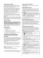
Readyour
this pressurewasher.
manual carefully and
becomefamiliar
with
Knowits
applications,
its limitations, and any hazards involved.
Important
Safety Information
_i, WARNING This product contains lead and lead
compounds, known to the State of California to cause
birth defects or other reproductive harm. Washyour
hands after handling this product.
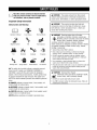
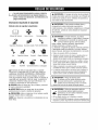
Safety Symbolsand Meanings
Operator'sManual
2
ToxicFumes
ElectricalShock
5-
SlipperySurface
Fire
_i, WARNING The engine exhaust from this product
contains chemicals known to the State of California to
cause cancer, birth defects, or other reproductive harm.
Fall
Explosion
_
FluidInjection
Kickback
Projectile
ChemicalBurn
reathing carbon monoxide could result in death,
serious injury, headache, fatigue, dizziness,
vomiting, confusion, seizures, nausea or fainting.
Some chemicals or detergents could be harmful if inhaled
or ingested, resulting in death, serious injury, nausea,
fainting or poisoning.
• Operatethis product ONLY outdoors.
• Keep exhaust gas from entering a confined area through
windows, doors, ventilation intakes, or other openings.
• DO NOToperate this product inside any building, carport,
porch, mobile equipment, marine applications, or enclosure,
even if windows and doors are open.
lib
MovingParts Flying Objects
,& WARNING Running engine gives off carbon
monoxide, an odorless, colorless, poison gas.
• Usea respirator or mask whenever there is a chancethat
vapors may be inhaled when using chemicals.
Hot Surface
,& The safety alert symbol indicates a potential personal
injury hazard. A signal word (DANGER,WARNING, or
CAUTION)is used with the alert symbol to designate a
degree or level of hazard seriousness. A safety symbol may
be used to represent the type of hazard. The signal word
NOTICEis used to address practices not related to personal
injury.
_i, DANGERindicates a hazardwhich, if not avoided, will
result in death or serious injury.
_i, WARNINGindicates a hazard which, if not avoided, could
result in death or serious injury.
_i, CAUTIONindicates a hazardwhich, if not avoided, could
result in minor or moderate injury.
flOTICEaddresspractices not relatedto personal injury.
• Read all instructions with mask so you are certain the mask will
provide the necessary protection against inhaling harmful
vapors when using chemicals.
,& WARNING Chemical Burn Hazard.
_::;;_,,_j
Chemicals could cause burns resulting in death,
_
serious injury, and/or property damage.
• DONOTusecausticliquidwith pressurewasher.
• UseONLYpressurewashersafedetergents/soaps.
Followall
manufacturersinstructions.
,& WARNING
,_can
Starter cord kickback (rapid retraction) will
pull hand and arm toward engine faster than you
let go which could cause broken bones,
fractures, bruises, or sprains resulting in serious
injury.
• NEVERpull starter cord without first relieving spray gun
pressure.
• When starting engine, pull cord slowly until resistance is felt
and then pull rapidly to avoid kickback.
• After each starting attempt, where engine fails to run, always
point spray gun in safe direction, press red button and squeeze
spray gun trigger to releasehigh pressure.
• Firmly grasp spray gun with both hands when using high
pressure spray to avoid injury when spray gun kicks back.
,& WARNING
Fuel and its vapors are extremely flammable
and explosive which could cause burns,
fire or explosion resulting in death,
serious injury and/or property damage.
WHENADDING OR DRAININGFUEL
• Turn pressure washer engine OFFand let it cool at least 2
minutes before removing fuel cap. Loosen cap slowly to relieve
pressure in tank.
• Fill or drain fuel tank outdoors.
• DO NOT overfill tank. Allow spacefor fuel expansion.
• If fuel spills, wait until it evaporates before starting engine.
• Keepfuel away from sparks, open flames, pilot lights, heat, and
other ignition sources.
• Checkfuel lines, tank, cap and fittings frequently for cracks or
leaks. Replaceif necessary.
_i_WARNING Risk of electrocution.
_.mm Contactwith power source could cause electric
shock or burn resulting in death or serious injury.
• DO NOT light a cigarette or smoke.
WHENSTARTINGEQUIPMENT
• Ensurespark plug, muffler, fuel cap, and air cleanerare in place.
• NEVERspraynearpowersource.
• DO NOTcrank engine with spark plug removed.
WHEN OPERATINGEQUIPMENT
_i, WARNING
• DO NOToperate this product inside any building, carport,
porch, mobile equipment, marine applications, or enclosure.
The high pressure stream of water that
and
underlying
tissues, could
resulting
in serious
this its
equipment
produces
cut through
skin
injury and possible amputation.
Spray gun traps high water pressure, even when engine is
stopped and water is disconnected, which could result in
serious injury.
• If cut by fluid, call physician immediately. DO NOTtreat as a
simple cut.
• DO NOTtip engine or equipment at angle which causes fuel to
spill.
• DO NOT spray flammable liquids.
WHENTRANSPORTING,MOVING OR REPAIRING EQUIPMENT
• Transport/move/repair with fuel tank EMPTYor with fuel shutoff
valve OFF.
• DO NOT allow CHILDRENto operate pressure washer.
• DO NOTtip engine or equipment at angle which causes fuel to
spill.
• NEVERrepair high pressure hose. Replaceit.
• Disconnect spark plug wire.
• NEVERrepair leaking connections with sealant of any kind.
Replaceo-ring or seal.
WHEN STORINGFUEL OR EQUIPMENTWITH FUEL IN TANK
• NEVERconnect high pressure hose to nozzle extension.
• Keep high pressure hose connected to pump and spray gun
while system is pressurized.
• ALWAYS point spray gun in safe direction, press red button
and squeezespray gun trigger to releasehigh pressure, every
time you stop engine.
• NEVERaim spray gun at people,animals, or plants.
• DO NOTsecure spray gun in open position.
• DO NOTleave spray gun unattended while machine is running.
• NEVERuse a spray gun which does not have a trigger lock or
trigger guard in place and in working order.
• Always be certain spray gun, nozzles and accessoriesare
correctly attached.
• Store away from furnaces, stoves, water heaters, clothes
dryers, or other appliancesthat have pilot light or other ignition
source becausethey could ignite fuel vapors.
,& WARNING
,_
Exhaust heat/gases could ignite
combustibles, structures or damage fuel
tank causing a fire, resulting in death,
serious injury and/or property damage.
Contact with muffler area could cause burns resulting in
serious injury.
• DO NOTtouch hot parts and AVOID hot exhaust gases.
• Allow equipment to cool before touching.
• Keep at least 5 feet (152 cm) of clearanceon all sides of
pressure washer including overhead.
• It is a violation of California Public ResourceCode, Section
4442, to use or operate the engine on any forest-covered,
brush-covered, or grass-covered land unless the exhaust
system is equipped with a spark arrester, as defined in Section
4442, maintained in effective working order. Other states or
federal jurisdictions may havesimilar laws.
Contact the original equipment manufacturer, retailer, or dealer
to obtain a spark arrester designed for the exhaust system
installed on this engine.
• Replacement parts must be the same and installed in the same
position as the original parts.
_. WARNING
Useofpressure
washer
couldcreate
puddles
andslippery
surfaces
causing
_
youtofallresulting
indeathorserious
IF
injury.
Kickback
fromsprayguncouldcause
youtofallresulting
indeath
orserious
injury.
• Operate
pressure
washer
fromastable
surface.
• Thecleaning
area
should
have
adequate
slopes
anddrainage
to
reduce
thepossibility
ofafallduetoslippery
surfaces.
• Beextremely
careful
ifyoumustusethepressure
washer
from
aladder,
scaffolding,
oranyother
similar
location.
• Firmly
grasp
spray
gunwithbothhands
when
using
high
pressure
spray
toavoid
injury
when
spray
gunkicks
back.
_i_ CAUTION Excessively high operating speeds could
result in minor injury and/or pressure washer damage.
Excessively low speeds impose a heavy load.
• DO NOTtamper with governor spring, links or other parts to
increase engine speed. Pressure washer supplies correct rated
pressure and flow when running at governed speed.
• DO NOTmodify pressure washer in any way.
NOTICE High pressure spray could damagefragile items
including glass.
• DONOTpointspraygunat glasswhenusingred (0°) spraytip.
• NEVER
aim spraygunat plants.
_i_WARNING Unintentional sparking could cause fire or
"_.m|h electric shock resulting in death or
serious injury.
WHENADJUSTING
ORMAKINGREPAIRS
TOYOURPRESSURE
WASHER
• Disconnect the spark plug wire from the spark plug and place
the wire where it cannot contact spark plug.
WHENTESTINGFOR ENGINESPARK
NOTICE Improper treatment of pressure washer could
damage it and shorten its life.
• If you have questions about intended use, ask dealer or contact
qualified service center.
• NEVERoperate units with broken or missing parts, or without
protective housing or covers.
• Use approved spark plug tester.
• DO NOT by-pass any safety device on this machine.
• DO NOT check for spark with spark plug removed.
• DO NOTtamper with governed speed.
• DO NOT operate pressure washer above rated pressure.
_. WARNING Starter and other rotating parts could
entangle
hair,
clothing, or accessories
resulting hands,
in serious
injury.
• NEVERoperatepressurewasherwithoutprotectivehousingor
covers.
• DONOTwearlooseclothing,jewelryor anythingthat couldbe
caughtin thestarteror otherrotatingparts.
• Tieup long hairand removejewelry.
_i, WARNING Risk of eye or bodily injury.
_:_
Spray could
objects
resulting
splash
in serious
back or injury.
propel
• Always wear indirect vented (chemical splash) safety goggles
marked to comply with ANSI Z87.1 when using or in vicinity of
this equipment.
• NEVERsubstitute safety glasses or dry-condition goggles for
indirect vented safety goggles.
• Always wear protective clothing such as a long-sleeved shirt,
long pants and close-toed shoes.
• NEVERoperate pressure washer when barefoot or wearing
sandals or shorts.
• DO NOT modify pressure washer in any way.
• Before starting pressure washer in cold weather, check all parts of
the equipment to be sure ice has not formed there.
• NEVERmove machine by pulling on hoses. Usehandle provided
on unit.
• This equipment is designedto be usedwith Sears authorized parts
ONLY.If equipment is usedwith parts that DO NOTcomply with
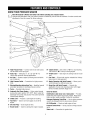
minimum specifications, user assumes all risks and liabilities.
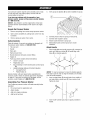
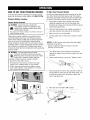
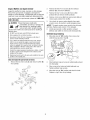
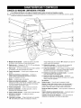
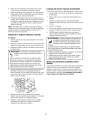
KNOWYOURPRESSUREWASHER
Read
the Operator'sManual
rules
before
pressure
Comparethe
illustrationswith and
yoursafety
pressure
washer
tooperatingyour
familiarize yourself
with washer.
the locationsof various controls and
adjustments. Savethis manual for future reference.
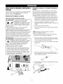
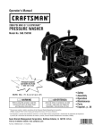
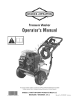
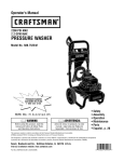
®
A - High PressureHose-- Connect one end to water pump
and the other end to spray gun.
M - EngineSwitch-- Set switch to "On" for recoil starting.
Set switch to "Off" to stop a running engine.
B - Spray Tips -- Detergent, 0°, 15°, 25° and 40°: for
various high pressure cleaning applications.
N - Throttle Lever -- Sets engine in starting mode for recoil
start.
C - Air Filter -- Protects engine by filtering dust and debris
out of intake air.
P - FuelTank -- Fill tank with regular unleaded fuel. Always
leave room for fuel expansion.
D - High PressureOutlet -- Connection for high pressure
hose.
R - Nozzle Extensionwith QuickConnect-- Allows you to
switch between five different spray tips.
E - Warning/OperatingInstructionsTag -- Identifies hazards
and proper procedure to start/stop pressure washer.
S - Spray Gun with Quick Connect-- Controls the
application of water onto cleaning surface with trigger
device. Includes automatic trigger lock.
F - Pump-- Developshigh pressure.
G - Automatic Cool DownSystem-- Cycles water through
pump when water reaches 125°-155°F. Warm water will
discharge from pump onto ground. This system prevents
internal pump damage.
H - ChokeLever-- Prepares a cold engine for starting.
J - Fuel Valve-engine.
Used to turn fuel supply on and off to
K - Oil Brain Plug-- Drain engine oil here.
L - Recoil Starter -- Used for starting the engine manually.
Items Not Shown:
Identification Label (near rear of base plate) -- Provides
model and serial number of pressure washer. Pleasehave
these numbers readily available if calling for assistance.
Detergent SiphoningTube/Filter -- Use to siphon pressure
washer safe detergent intothe low pressure stream.
Oil Fill/Dipstick-- Checkand add engine oil here.
PressureControlKnob-- Varies pressure of high pressure
spray.
Water Inlet -- Connection for garden hose.
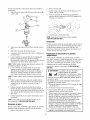
Yourpressure
washer
requires
someassembly
andisready
foruseonlyafterithasbeenproperly
serviced
withthe
recommended
oilandfuel.
5.
Verify pump oil dipstick (A) has been installed into pump.
6.
Connect pressure hose to spray gun and pump.
7.
Connect water supply to pump.
8.
9.
Attach nozzle extension to spray gun.
Select/attach quick connect spray tip to nozzle
extension.
If you have any problems with the assembly of your
pressurewasher, please call the pressurewasher helpline
at 1-800-222-3136.
NOTICE Any attempt to run the engine before it has been
serviced with the recommended oil will result in an engine
failure.
Unpackthe PressureWasher
1.
Remove everything from carton except pressure washer.
2.
Open carton completely by cutting each corner from top
to bottom.
3.
Remove pressure washer from carton.
CartonContents
Checkall contents. If any parts are missing or damaged,call
the pressurewasher helpline at 1-800-222-3136.
• The main unit
•
Handle
•
•
•
•
•
Spray gun
High pressure hose
Nozzleextension with quick connect fitting
Engine oil
Parts bag (which includes items listed below)
•
Owner's manual
•
•
•
Registration card
Bag containing 5 multi-colored quick connect spray
tips
HandleFasteningHardwareKit (which includes):
•
Carriage Bolt (2)
•
Plastic Knobs (2)
Become familiar with each piece before assembling the
pressure washer. Checkall contents against the illustration
on page 6. If any parts are missing or damaged, call the
pressure washer helpline at 1-800-222-3136.
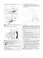
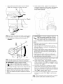
Attach Handle
1.
Placehandle (B) onto handle supports (C) connected to
main unit. Make sure holes (D) in handle align with
holes (D) on handle supports.
NOTICE It may be necessary to move the handle supports
from side to side in order to align the handle so it will slide
over the handle supports.
2.
Insert carriage bolts (E) through holes from outside of
unit and attach a plastic knob (F) from inside of unit.
Tighten by hand.
3.
Insert multi-colored spray tips in spaces provided in
handle.
Assembling Your Pressure Washer
Your Craftsman pressure washer will need assembly before
operation:
1.
2.
Fill out and send in registration card.
Attach handle.
3.
4.
Add oil to engine crankcase.
Add fuel to fuel tank.
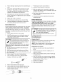
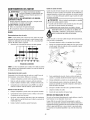
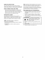
Add Engine Oil
1.
Place pressure washer on a flat, level surface.
2.
Cleanarea around oil fill and remove oil fill cap/dipstick.
3.
Using oil funnel (optional), slowly pour contents of both
provided oil bottles into oil fill opening to the point of
overflowing.
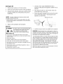
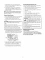
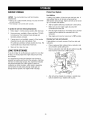
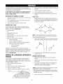
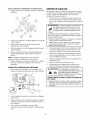
1. Use clean, fresh, regular UNLEADEDfuel with a
minimum of 86 octane with equipment. DO NOT mix oil
with fuel.
2.
Place pressure washer on a level surface. Cleanarea
around fuel fill cap, remove cap.
3.
Slowly add regular unleadedfuel to fuel tank. Be careful
not to overfill. Allow about 1" of tank space for fuel
expansion, as shown here.
MaximumFuelLevel
4.
Install fuel cap and wait for any spilled fuel to evaporate.
NOTICE Improper treatment of pressure washer could
damage it and shorten its life.
• DO NOT attempt to crank or start the engine before it has been
properly serviced with the recommended oil. This could result in
an engine failure.
4.
Replaceoil fill cap/dipstick and fully tighten.
Add Fuel
,& WARNING Fueland its vapors are extremely flammable
and explosivewhich could cause burns,
fire or explosion resulting in death,
serious injury and/or property damage.
WHENADDINGFUEL
• Turn pressure washer engine OFFand let it cool at least 2
minutes before removing fuel cap. Loosen cap slowly to relieve
pressure in tank.
• Fill fuel tank outdoors.
• DO NOT overfill tank. Allow spacefor fuel expansion.
• If fuel spills, wait until it evaporatesbefore starting engine.
• Keepfuel away from sparks, open flames, pilot lights, heat, and
other ignition sources.
• Checkfuel lines, tank, cap and fittings frequently for cracks or
leaks. Replaceif necessary.
• DO NOT light a cigarette or smoke.
CAUTION! Alcohol-blended fuels (called gasohol, ethanol or
methanol) can attract moisture, which leads to separation and
formation of acids during storage. Acidic gas can damagethe
fuel system of an engine while in storage.
To avoid engine problems, the fuel system should be treated
with a fuel preserver or emptied before storage of 30 days or
longer. If adding a fuel preserver, fill the fuel tank with fresh
fuel. If only partially filled, air in the tank will promote fuel
deterioration during storage. If fuel preserver is not used,
drain the fuel tank, start the engine and let it run until the fuel
lines and carburetor are empty. Use fresh fuel next season.
See Storage for additional information.
NEVERuse engine or carburetor cleaner products in the fuel
tank as permanent damage may occur.
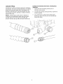
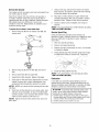
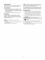
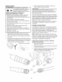
Lubricate O-Rings
Lubrication of o-rings is extremely important for installation
and operation. The use of a lubricant (petroleum or synthetic
grease) during assembly helps seat o-rings properly and
provides an improved seal. It also helps protect the o-ring
from damage by abrasion, pinching or cutting and extends
the life of the o-ring.
NOTICE ALWAYSapply a small amount of lubricant on
o-rings prior to assembling the garden hose to the pump
inlet (A), high pressure hose to pump outlet (B), high
pressure hose (C), spray gun (D), and nozzle extension (E).
Lubricateall connectionsshownbelow, followingthese
instructions:
1.
Inspect and clean connecting surfaces prior to
lubrication and assembly.
2.
Use lubricants sparingly during assembly; a light film is
all that is required.
3.
Use a small brush or cotton swab to apply grease
directly to o-rings where they are not accessible (QC
fitting, IVI22fitting).
4.
ConnectHose and Water Supplyto Pump
NOTICE DO NOT siphon standing water for the water
supply. Use ONLY cold water (less than 100°F).
NOTICE DO NOT run the pump without the water supply
connected and turned on.
• Damageto equipmentresultingfrom failureto follow this
instructionwill voidwarranty.
5.
NOTICE Remove and discard the shipping caps from the
pump's high pressure outlet and water inlet before attaching
hoses.
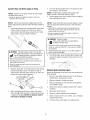
1.
Run water through garden hose for 30 seconds to clean
out any debris. Turn off water.
Connect garden hose (not to exceed 50 feet in length) to
water inlet.Tighten by hand.
NOTICE Using a One Way Valve (vacuum breaker or check
valve) at pump inlet could cause pump or inlet connector
damage.
• ThereMUSTbeat leastten feetof unrestrictedgardenhose
betweenthe pressurewasherinletandanydevice,suchasa
vacuumbreakeror checkvalve.
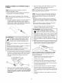
Uncoil high pressure hose and attach quick connect end
of hose to base of spray gun. Pull down on collar of
quick connect, slide onto spray gun and let go of collar.
Tug on hose to be sure of tight connection.
• Damageto equipment resulting from failure to follow this
instruction will void warranty.
,& WARNING Risk of eye injury.
Spray could splash back or propel objects
resulting in serious injury.
• Always wear indirect vented (chemical splash) safety goggles
marked to comply with ANSI Z87.1 when using or in vicinity of
this equipment.
• NEVERsubstitute safety glasses or dry-condition goggles for
indirect vented safety goggles.
_. WARNING The high pressure stream of water that
this equipment produces could cut through skin
6.
and its underlying tissues, resulting in serious
injury and possible amputation.
• NEVERconnect high pressure hose to nozzle extension.
Turn ONthe water, press red button (C) on the gun and
squeezethe trigger to purge the pump system of air and
impurities.
• Keep high pressure hose connected to pump and spray gun
while system is pressurized.
• Always be certain spray gun, nozzles and accessoriesare
correctly attached.
.
.
Similarly, attach other end of high pressure hose to high
pressure outlet (A) on pump. Pull down on collar of
quick connect, slide onto pump and let go of collar. Pull
on hose to be sure of tight connection.
Checklist Before Starting Engine
Reviewthe assembled unit to ensure you have performed all
of the following:
1. Be sure to read Safety Rules and How To Use Pressure
Washerbefore using pressure washer.
Before connecting garden hose to water inlet, inspect
inlet screen (B). Cleanscreen if it contains debris or have
it replacedif damaged. DO NOTrun pressure washer if
inlet screen is damagedor missing.
10
2.
Make sure handle is in place and secure.
3.
Make sure shipping cap was removed and oil dipstick
was installed in pump.
4.
Checkthat oil has been added to proper level in engine
crankcase.
5.
Add proper fuel to fuel tank.
6.
Checkfor properly attached hose connections.
7.
Checkto make sure there are no kinks, cuts, or damage
to high pressure hose.
8.
Provide a proper water supply at an adequateflow.
HOWTO USEYOURPRESSUREWASHER
To Start Your Pressure Washer
If you have any problems operating your pressure washer,
please call the pressure washer helpline at 1-888-222-3136.
To start your engine-powered pressure washer for the first
time, follow these instructions step-by-step. This starting
information also applies whenever you start the engine after
you have let the pressure washer sit idle for at least a day.
1. Placepressure washer near an outside water source
capableof supplying water at a flow rategreaterthan
5.0 gallons per minute and no less than 20 PSIat pressure
washer end of garden hose.
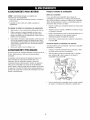
Pressure Washer Location
Pressure Washer Clearance
,&. WARNING Exhaust heat/gases could ignite
combustibles, structures or damagefuel tank
causing a fire, resulting in death, serious injury
and/or property damage.
• Keepat least5 ft. (152 cm) clearanceon all sidesof pressure
washerincludingoverhead.
Place pressure washer outdoors in an area that will not
accumulate deadly exhaust gas. DO NOT place pressure
washer where exhaust gas (A) could accumulate and enter
inside or be drawn into a potentially occupied building.
Ensure exhaust gas is kept away from any windows, doors,
ventilation intakes, or other openings that can allow exhaust
gas to collect in a confined area. Prevailing winds and air
currents should be taken into consideration when positioning
3ressure washer.
2.
Check that high pressure hose is tightly connected to
spray gun and pump. See Assemblyfor illustrations.
3.
Make sure unit is in a level position.
4.
Connect garden hose to water inlet on pressure washer
pump.
NOTICE DO NOT run the pump without the water supply
connected and turned on.
• Damageto equipmentresultingfrom failureto follow this
instructionwill voidwarranty.
,
,&. WARNING Running engine gives off carbon
monoxide, an odorless, colorless, poison gas.
_
reathing carbon monoxide could result in death,
serious injury, headache, fatigue, dizziness,
vomiting, confusion, seizures, nausea or fainting.
• Operatethis product ONLY outdoors.
,
Turn ON the water, press red button on the gun and
squeezethe trigger to purge the pump system of air and
impurities.
Attach nozzle extension to spray gun. Tighten by hand.
• Keep exhaust gas from entering a confined area through
windows, doors, ventilation intakes, or other openings.
• DO NOToperate this product inside any building, carport,
porch, mobile equipment, marine applications, or enclosure,
even if windows and doors are open.
7.
Choose spray tip you want to use, pull back on collar of
nozzle extension, insert spray tip and releasecollar. Tug
on spray tip to make sure it is securely in place. See
How to Use Spray Tips.
8.
Move fuel valve lever (B) to "On" position.
(_
11
OFF
9. Movethrottlelever(A)to"Fast"position,
shownasa
rabbit.
12. When starting engine, position yourself as
recommended and grasp starter grip handle and pull
slowly until you feel some resistance.Then pull rapidly
to start engine.
_J
jJ
/
/-
/
i,
10. Movechokelever(B)to"Closed"
position.
i
,/'
"
,_
OPEN
,/
CLOSED
NOTICE For a warm engine, be sure the choke lever is in the
"Open" position.
,&, WARNIN6 Starter cord kickback (rapid retraction) will
pull hand and arm toward engine faster than you
_'_t,_
can let go which could cause broken bones,
fractures, bruises, or sprains resulting in serious
injury.
• NEVERpull starter cord without first relieving spray gun
pressure.
11. Move engine switch (C) to "On" position.
E
OFF
• When starting engine, pull cord slowly until resistance is felt
and then pull rapidly to avoid kickback.
• After each starting attempt, where engine fails to run, always
point spray gun in safe direction, press red button and squeeze
spray gun trigger to releasehigh pressure.
• Firmly grasp spray gun with both hands when using high
pressure spray to avoid injury when spray gun kicks back.
13. Return recoil starter slowly. DO NOT let rope "snap
back" against starter.
ON
14. When engine starts, slowly move choke lever to "Open"
position as engine warms. If engine falters, move choke
lever to "Closed" position, then to "Open" position.
NOTICE Before starting the pressure washer, be sure you
are wearing safety goggles as described below.
,& WARNIN6 Risk of eye injury.
Spray could splash back or propel objects
resulting in serious injury.
15. If engine fires, but does not continue to run,always point
gun in safe direction, press red botton and squeezespray
gun trigger to releasehigh pressure. Move choke lever to
"Open" position, and repeatsteps 12 through 14.
• Always wear indirect vented (chemical splash) safety goggles
marked to comply with ANSI Z87.1 when using or in vicinity of
this equipment.
16. If engine fails to start after six pulls, move choke lever to
"Open" position, and repeatsteps 12 through 14.
• NEVERsubstitute safety glasses or dry-condition goggles for
indirect vented safety goggles.
NOTICE Always keep the throttle lever in the "Fast" position
when operating the pressure washer.
12
How to Stop Your Pressure Washer
,& WARNING The high pressure stream of water that
and
underlying
tissues,could
resulting
in serious
this its
equipment
produces
cut through
skin
injury and possible amputation.
Spray gun traps high water pressure, even when engine is
stopped and water is disconnected, which could result in
serious injury.
• DONOTallowCHILDREN
to operatepressurewasher.
• Keephigh pressurehoseconnectedto pumpand spraygun
whilesystemis pressurized.
• NEVERaimspraygun at people,animals,or plants.
• DONOTsecurespraygun in openposition.
• DONOTleavespraygun unattendedwhilemachineis running.
1.
Release spray gun trigger and let engine idle for two
minutes.
2.
Move throttle lever to "Slow" position, shown as a turtle.
3.
Move engine switch to "Off" position.
4.
Move fuel valve lever to "Off" position.
,& WARNING
Fuel and its vapors are extremely flammable
and explosive which could cause burns,
fire or explosion resulting in death,
serious injury and/or property damage.
• DO NOT stop engine by moving choke leverto "Choke" position.
5.
• NEVERusea spraygun whichdoesnothavea triggerlockor
trigger guardin placeand in workingorder.
• Alwaysbe certainspraygun,nozzlesandaccessories
are
correctlyattached.
ALWAYS point spray gun in a safe direction, push red
button and squeezespray gun trigger to release retained
high water pressure.
_, WARNING The high pressure stream of water that
and
underlying
tissues,could
resulting
in serious
this its
equipment
produces
cut through
skin
injury and possible amputation.
Spray gun traps high water pressure, even when engine is
stopped and water is disconnected, which could result in
serious injury.
• Keephigh pressurehoseconnectedto pumpand spraygun
whilesystemis pressurized.
• ALWAYSpointspraygun in safedirection,pressredbutton
andsqueezesprayguntriggerto releasehighpressure,every
time youstop engine.
,& WARNING
Exhaust heat/gases could ignite
combustibles, structures or damage fuel
tank causing a fire, resulting in death,
serious injury and/or property damage.
Contact with muffler area could cause burns resulting in
serious injury.
• DO NOTtouch hot parts and AVOID hot exhaust gases.
• Allow equipment to cool before touching.
• Keepat least 5 feet (152 cm) of clearanceon all sides of
pressure washer including overhead.
• It is a violation of California Public Resource Code,Section
4442, to use or operate the engine on any forest-covered,
brush-covered, or grass-covered land unless the exhaust
system is equipped with a spark arrester, as defined in Section
4442, maintained in effective working order. Other states or
federal jurisdictions may havesimilar laws.
Contact the original equipment manufacturer, retailer, or dealer
to obtain a spark arrester designed for the exhaust system
installed on this engine.
• Replacement parts must be the same and installed in the same
position as the original parts.
13
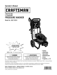
Cleaningand ApplyingDetergent
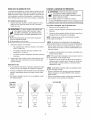
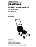
How to Use Spray Tips
The quick-connect on the nozzle extension allows you to
switch between four different quick connect spray tips. Spray
tips can be changed while pressure washer is running once
spray gun trigger lock is engaged. The spray tips vary the
spray pattern as shown below.
,A WARNING Chemical Burn Hazard.
_::;;;_,,Chemicals could cause burns resulting in death,
_
serious injury, and/or property damage.
• DONOTusecausticliquidwith pressurewasher.
• UseONLYpressurewashersafedetergents/soaps.
Followall
manufacturersinstructions.
Follow these instructionsto changespray tips:
1. Pull back collar on quick-connect and pull current spray
tip off. Store spray tips in holes provided in the handle.
To apply detergent, follow these steps:
,_ WARNING The high pressure stream of water that
and
underlying
tissues,could
resulting
in serious
this its
equipment
produces
cut through
skin
injury and possible amputation.
• NEVERexchangespraytips withoutthetriggerlock being
engagedon the spraygun.
DONOTtwist spraytips whilespraying.
2.
2.
Prepare detergent solution as required by job.
3.
Placesmall filter end of detergent siphoning tube into
detergent container.
NOTICE Contact with the hot muffler could damage
detergent siphoning tube.
• When inserting the siphon into a detergent solution bottle, route
the tube so as to keep it from inadvertently contacting the hot
muffler.
To scour surface, select yellow 15° or red 0° spray
tip.
To apply detergent, select black spray tip.
•
,
Review use of spray tips.
NOTICE Make sure the filter is fully submerged in detergent
while applying detergent.
Select desired spray tip:
•
For gentle rinse, select white 40° or green 25° spray
tip.
•
1.
4.
Pull back on collar, insert new spray tip and release
collar. Tug on spray tip to make sure it is securely in
place.
Make sure black spray tip is installed.
NOTICE Detergentcannot be applied with the high pressure
spray tips (White, Green,Yellow, or Red).
5. Make sure garden hose is connected to water inlet.
Checkthat high pressure hose is connected to spray gun
and pump. Turn on water.
Usage Tips
•
For most effective cleaning, keep spray tip from 8 to
24 inches (20 to 61 cm) away from cleaning surface.
•
If you get spray tip too close, especially using a high
pressure spray tip, you may damage surface being
cleaned.
NOTICE You must attach all hoses before you start the
engine.
• Starting the engine without all the hoses connected and without
the water turned ON could damage the pump.
•
DONOT get closer than 6 inches (15 cm) when cleaning
tires.
• Damageto equipment resulting from failure to follow this
instruction will void warranty.
6.
LOWPressure
Start engine following instructions How to Start Your
Pressure Washer.
High Pressure
\
I
D
I
J
D L
D
I
L
J
Useto
apply
detergent
Black
White
40°
Green
25°
14
Yellow
15°
Red
0°
7. Applydetergent
toa drysurface,
starting
atlower
portionofareatobewashed
andworkupward,
using
long,even,
overlapping
strokes.
8. Allowdetergent
to"soakin"for3-5minutes
before
washing
andrinsing.Reapply
asneeded
toprevent
surface
fromdrying.DONOT
allowdetergent
todryon
(prevents
streaking).
Cleaning DetergentSiphoningTube
If you used the detergent siphoning tube, you must flush it
with clean water before stopping the engine.
1. Remove high pressure spray tip from nozzle extension.
NOTICE You must flush the detergent siphoning system
after each use by placing the filter into a bucket of clean
water, then run the pressure washer with black detergent
nozzle for 1-2 minutes.
Remove black detergent spray tip from nozzle extension.
2.
Select and install desired high pressure spray tip
following instructions How to Use Spray Tips.
3.
Start at top of area to be rinsed, working down with
same overlapping strokes as you used for cleaning.
ALWAYS point spray gun in a safe direction, press red
button and squeezespray gun trigger to release retained
high water pressure.
AutomaticCool DownSystem
(Thermal Relief)
Increase (decrease) spray pressure by turning pressure
control knob (A) clockwise (counterclockwise). Use
lower pressure to wash items such as a car or boat. Use
higher pressure to strip paint and degrease driveways.
6.
Shut off engine following instructions How to Stop
Pressure Washerand turn off water supply.
and
underlying
tissues,could
resulting
in serious
this its
equipment
produces
cut through
skin
injury and possible amputation.
Spray gun traps high water pressure, even when engine is
stopped and water is disconnected, which could result in
serious injury.
• Keephigh pressurehoseconnectedto pumpand spraygun
whilesystemis pressurized.
• ALWAYSpointspraygun in safedirection,pressredbutton
andsqueezesprayguntriggerto releasehighpressure,every
time youstop engine.
• Operatepressurewasherfrom a stablesurface.
• Beextremelycarefulif you mustusethe pressurewasherfrom
a ladder,scaffolding,or anyothersimilarlocation.
• Firmlygraspspraygun with bothhandswhen usinghigh
pressuresprayto avoidinjurywhenspraygun kicks back.
Apply a high pressure spray to a small area and then
check the surface for damage. If no damage is found,
you can assume it is okay to continue rinsing.
Flush for 1-2 minutes.
,_, WARNIN6 The high pressure stream of water that
Kickback from spray gun could cause you
5.
Placedetergent siphoning tube/filter in a bucket full of
clean water.
,
to fall resulting in death or serious injury.
,
3.
5.
Keep spray gun a safe distance from areayou plan to
spray.
,_. WARNIN6
Select and install black detergent spray tip.
,
Pressure Washer Rinsing
1.
2.
If you run the engine on your pressure washer for
3-5 minutes without pressing the trigger on the spray gun,
circulating water in the pump can reach temperatures above
125°F. The system engages to cool the pump by discharging
the warm water ontothe ground.
15
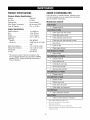
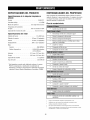
PRODUCT SPECIFICATIONS
OWNER'SRESPONSIBILITIES
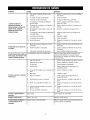
Pressure Washer Specifications
Follow the hourly or calendar intervals, whichever occurs
first. More frequent service is required when operating in
adverse conditions noted below.
Pressure .....................
Flow Rate.....................
3,800 PSI*
4.0 GPM
Detergent Mix .................
Water Supply Temperature .......
Pump Oil Capacity..............
Use as directed
Not to exceed IO0°F
12 fl. oz. (0.35 I)
MaintenanceSchedule
•
Changeengine oil
•
Check/clean waterinlet screen'
•
Check high pressure hose
•
Check detergent siphoning hose
•
Check spray gun and assembly for leaks
•
Cleandebris
•
Check air filter
•
Check engine oil level
•
Cleanair filter2
•
Change engine oil
•
Cleansediment cup
•
Check/adjust spark plug
•
Service spark arrester'
•
Clean fueltank and filter
•
Changepump oils
•
Replace air filteP
•
Replace spark plug
•
Check adjust idle speed4
•
Check adjust valve clearance4
•
Cleancumbustion chambeP
•
Check fuel tube (replace if necessary?
Engine Specifications
RatedHorsepower ...............
Bore ..........................
Stroke .........................
Displacement ...................
Spark Plug
Resistor ....................
Set GapTo: ...................
IntakeValveClearance ............
ExhaustValveClearance...........
FuelCapacity ...................
Oil Type .......................
13 at 3600 rpm
3.5 in. (88 mm)
2.5 in. (64 mm)
23.7 in. (389 cc)
NGK BPR6ES
0.028-0.031 in (0.70-0.80
mm)
0.15 ± 0.02 mm (cold)
0.20 ± 0.02 mm (cold)
1.72 Gallons
SAE10W-30
* This pressure washer is rated in accordanceto the
Pressure Washer Manufacturers Association (PWMA)
standard PW101 (Testing and Rating Performance of
Pressure Washers).
Cleanif clogged. Replaceif perforated or torn.
2
16
Service more often under dirty or dusty conditions.
3
Replacepaper element only.
4
These items should be serviced by your servicing dealer.
5
Changeafter first 50 hours of operationand then every 200 hours or 3 months,
whichever occurs first.
GeneralRecommendations
Checkand CleanInlet Screen
Regular maintenancewill improve the performance and
extend the life of the pressure washer. See any Sears or
other qualified service dealer for service.
Examine garden hose inlet screen. Clean if it is clogged or
replace if it is torn.
CheckHigh Pressure Hose
The pressure washer warranty does not cover items that
have been subjected to operator abuse or negligence. To
receive full value from the warranty, the operator must
maintain pressure washer as instructed in this manual
including proper storage as detailed in Storage.
High pressure hoses can develop leaks from wear, kinking,
or abuse. Inspect hose before each use. Checkfor cuts,
leaks, abrasions, bulging of cover, or damage or movement
of couplings. If any of these conditions exist, replace hose
immediately.
Some adjustments will need to be made periodically to
properly maintain your pressure washer.
_, WARNING The high pressure stream of water that
All service and adjustments should be made at least once
each season. Follow the requirements in the Maintenance
Schedule chart.
and
underlying
tissues,could
resulting
in serious
this its
equipment
produces
cut through
skin
injury and possible amputation.
• NEVERrepairhigh pressurehose.Replaceit.
• ReplacementhoseratingMUSTequalor exceedmaximum
pressureratingof unit.
NOTICE Oncea year you should clean or replace the spark
plug and replacethe air filter. A new spark plug and clean air
filter assure proper fuel-air mixture and help your engine run
better and last longer.
CheckGunand Nozzle Extension
Emissions Control
Examine hose connection to spray gun and make sure it is
secure. Test trigger by pressing it and making sure it springs
back into placewhen you releaseit. Do not depress red
button and test trigger. You should not be able to press
trigger. Replace spray gun immediately if it fails any of these
tests.
Maintenance, replacement, or repair of the emissions
controldevices and systemsmay be performedby any nonroad engine repair establishmentor individual. However,
to obtain "no charge" emissions control service, the work
must be performed by a factory authorized dealer. See the
Emissions Warranty.
Detergent Siphoning Check Ball
Before EachUse
1.
2.
Check engine oil level.
Cleandebris.
Occasionally check ball in detergent siphoning system may
become stuck from storage, dried soap, or minerals in water.
The check ball can be freed by performing the following:
3.
4.
Checkwater inlet screen for damage.
Check high pressure hose for leaks.
NOTICE Before performing this procedure, be sure you are
wearing safety goggles as described below.
5.
Check gun and nozzle extension assembly for leaks.
6.
Purge pump of air and contaminants.
_i, WARNING Risk of eye injury.
Spray could splash back or propel objects
resulting in serious injury.
PRESSUREWASHERMAINTENANCE
• Always wear indirect vented (chemical splash) safety goggles
marked to comply with ANSI Z87.1 when using or in vicinity of
this equipment.
Clean Debris
Daily or before use, clean accumulated debris from pressure
washer. Keep linkage, spring and controls clean. Keeparea
around and behind muffler free from any combustible debris.
Inspect cooling air slots and openings on the pressure
washer. These openings must be kept clean and
unobstructed.
• NEVERsubstitute safety glasses or dry-condition goggles for
indirect vented safety goggles.
Shut off engine and turn off water supply.
.
Pressure washer parts should be kept clean to reduce the
risk of overheating and ignition of accumulated debris.
•
_i, WARNING The high pressure stream of water that
Use a damp cloth to wipe exterior surfaces clean.
and
underlying
tissues,could
resulting
in serious
this its
equipment
produces
cut through
skin
injury and possible amputation.
Spray gun traps high water pressure, even when engine is
stopped and water is disconnected, which could result in
serious injury.
• Keephigh pressurehoseconnectedto pumpand spraygun
whilesystemis pressurized.
• ALWAYSpointspraygun in safedirection,pressredbutton
andsqueezesprayguntriggerto releasehighpressure,every
time youstop engine.
NOTICE Improper treatment of pressure washer could
damage it and shorten its life.
• DONOTinsertany objectsthroughcoolingslots.
•
Use a soft bristle brush to loosen caked on dirt, oil, etc.
•
Use a vacuum cleaner to pick up loose dirt and debris.
ALWAYS point spray gun in a safe direction, press red
button and squeezespray gun trigger to release retained
high water pressure.
17
,
4.
Remove detergent siphoning hose from barbed fitting on
7.
Reinstall spray tip into nozzleextension.
pump.
8.
Reconnect nozzle extension to spray gun.
Using a firm, blunt object 7/64" in diameter or smaller,
by at least 1" long, such as an Allen wrench, slowly
insert the object into the barbed fitting until you meet
resistance.This resistance is the check ball.
9.
Make sure garden hose is connected to water inlet.
Checkthat high pressure hose is connected to spray gun
and pump. Turn on water.
10. Start engine following instructions How to Start Your
Pressure Washer.
Slowly push down until you feel the ball move slightly,
push no more than 1/8". Slight pressure may be required
to free the ball.
,
11. Test pressure washer by operating with each quick
connect spray tip.
6.
Repeatsteps 4 and 5 if necessary.
7.
Reinstall detergent siphoning hose onto barb fitting.
O-Ring Maintenance
8.
Treat with PumpSaver as described in Protecting the
Pump during storage to prevent reoccurrence.
Purchasean O-Ring RepairKit at your local Searsor by calling
1-800-4-MY-HOME(489-4683) or online at www.sears.com. It
is not includedwith the pressurewasher.This kit includes
replacemento-rings, rubberwasher and water inletfilter. Referto
the instruction sheetprovidedin the kit to serviceyour unit's
o-rings.
Nozzle Maintenance
A pulsing sensation felt while squeezing the spray gun trigger
may be caused by excessivepump pressure. The principal
cause of excessive pump pressure is a spray tip clogged or
restricted with foreign materials, such as dirt, etc. To correct
the problem, immediately clean the spray tip following these
instructions:
1.
Shut off engine and turn off water supply.
2.
ALWAYS point spray gun in a safe direction, press red
button and and squeezespray gun trigger to release
retained high water pressure.
WARNIN6 The high pressure stream of water that
and
underlying
tissues,could
resulting
in serious
this its
equipment
produces
cut through
skin
injury and possible amputation.
• NEVERrepairleakingconnectionswith sealantof any kind.
Replaceo-ring or seal.
Pump Maintenance
ChangingPump Oil
,A WARNIN6 The high pressure stream of water that
Changeoil after first 50 hours of operation and then every
200 hours or 3 months, whichever occurs first.
and
underlying
tissues,could
resulting
in serious
this its
equipment
produces
cut through
skin
injury and possible amputation.
Spray gun traps high water pressure, even when engine is
stopped and water is disconnected, which could result in
serious injury.
• Keephigh pressurehoseconnectedto pumpand spraygun
whilesystemis pressurized.
• ALWAYSpointspraygun in safedirection,pressred button
andsqueezesprayguntriggerto releasehighpressure,every
time you stop engine.
NOTICE When changing pump oil, use only high quality
nondetergent 30 weight oil. Use no special additives.
Changepump oil as follows:
1.
Cleanarea around brass oil drain plug at bottom of
pump.
2.
Remove oil drain plug. Drain oil completely into an
approved container.
3.
Remove spray tip from end of nozzle extension.
3.
4.
Use a small paper clip to free any foreign material
clogging or restricting spray tip (A).
When oil has completely drained, install oil drain plug
and tighten firmly.
4.
Cleanarea around pump oil dipstick. Remove dipstick
and fill pump with recommended oil to "Full" mark on
dipstick (typically 0.35L or 12 oz.).
,
6.
5.
Remove nozzle extension from spray gun.
6.
Using a garden hose, remove additional debris by back
flushing water through nozzle extension. Back flush
between 30 to 60 seconds.
J
J
18
Install pump oil dipstick.
Wipe up any spilled oil.
ENGINEMAINTENANCE
ChangingEngineOil
Changeengine oil after the first 20 hours and every
100 hours or 6 months, whichever comes first, thereafter. If
you are using your pressure washer under extremely dirty or
dusty conditions, or in extremely hot weather, change oil
more often.
_. WARNING Unintentional sparking could cause fire or
"_,ah electric shock resulting in death or
serious injury.
WHENADJUSTING
ORMAKINGREPAIRS
TOYOURPRESSURE
WASHER
• Disconnect the spark plug wire from the spark plug and place
the wire where it cannot contact spark plug.
WHENTESTINGFOR ENGINESPARK
_i, CAUTION Avoid prolonged or repeated skin contact
with used motor oil.
• Used motor oil has been shown to cause skin cancer in certain
laboratory animals.
• Use approved spark plug tester.
• Thoroughly wash exposed areas with soap and water.
• DO NOT check for spark with spark plug removed.
KEEPOUT OFREACHOF CHILDREN.DON'T
POLLUTE.CONSERVERESOURCES.RETURN
USEDOIL TO COLLECTIONCENTERS.
Oil
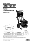
Oil Recommendations
NOTICE When adding oil to the engine crankcase, use only
high quality 4-stroke automotive detergent oil rated with API
service classification SJ or SL rated SAE 10W-30 weight. DO
NOT use special additives.
1.
Changeoil while engine is still warm from running, as
follows:
1.
Disconnect spark plug wire and keep it away from spark
plug.
2.
Placea suitable container below engine to catch used
oil. Removedipstick (A), drain plug (B) and washer.
Choose a viscosity according to table below.
I
-20
Iow.-3o
0
20
I
I
I
-30
-20
-10
40
60
80
100 °F
I
I
I
I
0
10
20
30
I
40°0
J
AMBIENT
TEMPERATURE
NOTICE Other viscosities shown in the chart may be used
when the averagetemperature in your area is within the
recommended range.
CheckingOil Level
Oil level should be checked prior to each use or at least every
8 hours of operation. Keepoil level maintained.
LOWER
LiMiT
3.
Allow oil to drain completely. Reinstall drain plug and
washer. Tighten drain plug securely.
4.
Place pressure washer on a level surface.
5.
Slowly pour recommended oil into oil fill opening (C).
Pauseto permit oil to settle. Fill to edge of oil filler hole.
6.
Screw in the dipstick and tighten securely.
AddingEngine Oil
7.
Wipe up any remaining oil.
1.
Make sure pressure washer is on a level surface.
8.
Reconnect spark plug wire to spark plug.
2.
Check oil level as described in Checking Oil Level
3.
If needed,slowly pour oil into oil fill opening. Pauseto
permit oil to settle. Fill to edge of oil filler hole.
4.
Replace and tighten dipstick.
1.
Make sure pressure washer is on a level surface.
2.
Cleanarea around dipstick. Removeoil dipstick and wipe
dipstick with clean cloth. Replacedipstick. Remove and
check oil level.
3.
Verify oil is at "Full" mark on dipstick. Replaceand
tighten dipstick.
19
ServiceAir Cleaner
7.
Using a moist rag, wipe dirt from inside of air cleaner
base and cover. Be careful to prevent dirt from entering
air duct that leadsto the carburetor.
8.
Placefoam air filter element over paper element and
reinstall assembled air filter. Be sure gasket is in place
beneath air filter. Tighten air filter wing nut securely.
9.
Install air cleaner cover and tighten cover wing nut
securely.
Your engine will not run properly and may be damaged if you
run it with a dirty air cleaner.
Cleanthe air cleaner once every 50 hours of operation or
3 months, whichever comes first. Service more often if
operating under dirty or dusty conditions. Replacethe paper
filter element once every 300 hours or once a year,
whichever comes first. Replacementsare available at your
local Sears service center.
NOTICE You can purchase new air filter elements by calling
1-800-4-1VlY-NOIVlE
(469-4663).
To service the air cleaner, follow these steps:
1.
Remove wing nut (A) from air cleaner cover (B), and
remove cover.
ServiceSparkPlug
Check and adjust the spark plug every 100 hours of
operation or yearly, whichever occurs first. Replacethe spark
plug every 300 hours of operation or yearly, whichever
occurs first.
1.
Cleanarea around spark plug.
2.
Remove and inspect spark plug.
3.
Replace spark plug if electrodes are worn, or if insulator
is cracked or chipped.
4.
Check electrode gap with wire feeler gauge and set gap
at 0.028-0.031 inches (0.70-0.80 mm), if necessary.
filter.
5.
Install spark plug, tighten securely.
3.
Remove foam filter (E) from paper filter.
NOTICE You can purchase a new spark plug by calling
1-800-4-1VlY-HOIVlE
(469-4663).
4.
Inspect both air filter elements.Replaceif damaged.
5.
Cleanpaper air filter element by tapping filter on a hard
surface to remove dirt, or blow compressed air (not
exceeding 30 psi) through filter element from inside.
2.
Remove wing nut (C) from air filter (D), and remove
Carburetor
If you think your carburetor needs adjusting, see your
nearest Sears service center. Engine performance may be
affected at altitudes above 5000 feet. For operation at higher
elevations, contact your nearest Sears service center.
NOTICE NEVERtry to brush off dirt; brushing will force dirt
into fibers.
6.
_i_ CAUTION Excessively high operating speeds could
result in minor injury and/or pressure washer damage.
Excessively low speeds impose a heavy load.
• DO NOTtamper with governor spring, links or other parts to
increase engine speed. Pressure washer supplies correct rated
pressure and flow when running at governed speed.
Cleanfoam air filter element in warm soapy water, rinse
and allow to dry thoroughly. Or clean in nonflammable
solvent and allow to dry. Dip foam filter element in clean
engine oil, then squeeze out all excess oil.
NOTICE Engine will smoke when started if too much oil is
left in foam.
• DO NOTmodify pressure washer in any way.
2O
InspectMuffler and SparkArrester
Inspect the muffler for cracks, corrosion, or other damage.
Removethe spark arrester, if equipped,and inspect for
damageor carbon blockage. If replacementparts are required,
make sure to use only original equipment replacementparts.
If you need to order a spark arrester, pleasecall 1-800-4-MYHOME(469-4663).
,A WARNING
Exhaust heat/gases could ignite
combustibles, structures or damage fuel
2.
Remove the three 4 mm screws (C) from exhaust
deflector (D), and remove deflector.
3.
Remove the four 5 mm screws (E) from muffler
protector (F) and remove muffler protector.
4.
Remove 4 mm screws (G) from spark arrester (H) and
remove spark arrester from muffler.
5.
Use a brush to remove carbon deposits from spark
arrestor screen. Be careful to avoid damaging screen.
NOTICE The spark arrestor screen must be free of breaks
and holes. Replacespark arrestor if it is damaged.
6. Install spark arrestor, muffler protector, exhaust
deflector and muffler in reverse order of disassembly.
tank causing a fire, resulting in death,
serious injury and/or property damage.
Contact with muffler area could cause burns resulting in
serious injury.
• DO NOTtouch hot parts and AVOID hot exhaust gases.
SedimentCupCleaning
• Allow equipment to cool before touching.
• Keepat least 5 feet (152 cm) of clearanceon all sides of
pressure washer including overhead.
1.
Move fuel valve to "Off" position, then remove fuel
sediment cup (J) and o-ring (K).
2.
Wash sediment cup and o-ring in nonflammable solvent.
Dry thoroughly.
3.
Place o-ring in fuel valve and install sediment cup.
Tighten sediment cup securely.
4.
Move fuel valve to "On" position and check for leaks.
Replace o-ring if there is any leakage.
• It is a violation of California Public Resource Code,Section
4442, to use or operate the engine on any forest-covered,
brush-covered, or grass-covered land unless the exhaust
system is equipped with a spark arrester, as defined in Section
4442, maintained in effective working order. Other states or
federal jurisdictions may havesimilar laws.
Contact the original equipment manufacturer, retailer, or dealer
to obtain a spark arrester designed for the exhaust system
installed on this engine.
• Replacement parts must be the same and installed in the same
position as the original parts.
Cleanandinspectthesparkarresteras follows:
1.
Remove the two 8 mm nuts (A) and remove muffler (B)
from cylinder.
21
AFTER EACH USE
Water should not remain in the unit for long periods of time.
Sediments or minerals can deposit on pump parts and
"freeze" pump action. Follow these procedures after every
use:
1.
Shut off engine, turn off water supply, point gun in a
safe direction, press red button and squeezetrigger to
relieve trapped pressure and let engine cool.
,A WARNING The high pressure stream of water that
and
underlying
tissues,could
resulting
in serious
this its
equipment
produces
cut through
skin
injury and possible amputation.
Spray gun traps high water pressure, even when engine is
stopped and water is disconnected, which could result in
serious injury.
• Keephigh pressurehoseconnectedto pumpand spraygun
whilesystemis pressurized.
• ALWAYSpointspraygun in safedirection,pressred button
andsqueezesprayguntriggerto releasehighpressure,every
time you stop engine.
2.
Disconnect hose from spray gun and high pressure
outlet on pump. Drain water from hose, gun, and spray
tip extension. Use a rag to wipe off the hose.
3.
Empty pump of all pumped liquids by pulling recoil
handle about 6 times. This should remove most liquid in
pump.
4.
Coil high pressure hose on hook provided on handle.
5.
Store unit in a clean, dry area.
6.
If storing for more than 30 days see Long Term Storage
on next page.
,A WARNING Fueland its vapors are extremelyflammable
and explosivewhich could causeburns,
fire or explosion resulting in death,
serious injury and/or property damage.
WHENSTORINGFUELOREQUIPMENT
WITH FUELIN TANK
• Storeawayfrom furnaces,stoves,waterheaters,clothes
dryers,or otherappliancesthat havepilot light or other
ignitionsourcebecausethey can ignitefuel vapors.
22
WINTERSTORAGE
Protect Fuel System
Fuel Additive:
NOTICE You must protect your unit from freezing
temperatures.
• Failureto do so will permanentlydamageyour pumpand render
your unit inoperable.
• Freezedamageis not coveredunderwarranty.
If adding a fuel additive, fill the fuel tank with fresh fuel. If
only partially filled, air in the tank will promote fuel
deterioration during storage. Engine and fuel can be stored
up to 24 months with additive.
•
Add fuel additive following manufacturer's instructions.
•
Make sure you havewater supply to pump inlet
connected and turned ON.
•
Run the engine outdoors for 10 minutes to be sure that
treated fuel has replacedthe untreated fuel in the
carburetor.
•
Stop engine and move fuel valve lever to "Off" position.
To protect the unit from freezing temperatures:
1.
Follow steps 1-4 in the previous section AfterEach Use.
2.
Use pump saver, availableat Sears retail item 7174403,
to treat pump. This minimizes freeze damage and
lubricates pistons and seals.
3.
4.
Draining FuelTank and Carburetor:
If pump saver is not available, connect a 3-foot section
of garden hose to water inlet adapter. Pour
RV-antifreeze (antifreeze without alcohol) into hose. Pull
recoil handle twice. Disconnect 3-foot hose.
If fuel additive is not used, remove all fuel from tank and
carburetor.
•
Place an approved fuel container below carburetor and
use a funnel to avoid spilling fuel.
•
Remove carburetor drain bolt (A) and sediment cup (B),
then move fuel valve lever to "On" position.
•
After all fuel has drained into container, reinstall drain
bolt and sediment cup. Tighten both securely.
Store unit in a clean, dry area.
LONGTERMSTORAGE
If you do not plan to use the pressure washer for more than
30 days, you must prepare the engine and pump for long
term storage.
It is important to prevent gum deposits from forming in
essential fuel system parts such as the carburetor, fuel filter,
fuel hose or tank during storage. Also, experience indicates
that alcohol-blended fuels (called gasohol, ethanol or
methanol) can attract moisture, which leadsto separation
and formation of acids during storage. Acidic gas can
damage the fuel system of an engine while in storage.
23
NOTICE PumpSaver is available as an optional accessory. It
is not included with the pressure washer. Contact your local
Searsservice center to purchase PumpSaver.
Change EngineOil
While engine is still warm, drain oil from crankcase. Refill
with recommended grade. See Changing Engine Oil.
To use PumpSaver, make sure the pressure washer is turned
off and disconnected from supply water. Readand follow all
instructions and warnings given on the PumpSaver container.
Oil Cylinder Bore
•
•
Removespark plug. Squirt about 1 tablespoon of clean
engine oil into the cylinder. Cover spark plug hole with
rag. Pull recoil handle slowly to distribute oil. Avoid spray
from spark plug hole.
Other StorageTips
1.
DO NOTstore fuel from one season to another unless it
has been treated as described in Protect Fuel System.
2.
Replacefuel container if it starts to rust. Rust and/or dirt
in fuel can cause problems if it's used with this unit.
3.
Cover unit with a suitable protective cover that does not
retain moisture.
Install spark plug. DO NOT connect spark plug wire.
Protect Pump
To protect the pump from damage caused by mineral
deposits or freezing, use PumpSaver,Sears retail item
7174403, to treat pump. This prevents freeze damage and
lubricates pistons and seals.
_i_ WARNING Storage covers could cause a fire
resulting in death, serious injury and/or property
damage.
NOTICE You must protect your unit from freezing
temperatures.
• Failure to do so will permanently damage your pump and render
your unit inoperable.
• Freezedamage is not covered under warranty.
• DO NOT place a storage cover over a hot pressure washer.
• Let equipment cool for a sufficient time before placing the
cover on the equipment.
4.
24
Store unit in a clean and dry area.
Problem
Cause
Correction
1.
Low pressurespray tip installed.
1.
Replacespray tip with high pressure
spray tip.
2.
Water inlet is blocked.
2.
Clear inlet.
3.
Inadequatewater supply.
3.
Provide adequatewater flow.
Inlet hose is kinked or leaking.
4.
Straighten inlet hose, patch leak.
Cloggedinlet hose strainer.
5.
Checkand clean inlet hose strainer.
Water supply is over IO0°F.
6.
Provide cooler water supply.
High pressure hose is blocked or
leaks.
7.
Clear blocks in outlet hose.
8.
Gun leaks.
8.
Replacegun.
9.
Spray tip is obstructed.
9.
Cleanspray tip.
4.
Pump has following problems: failure
to produce pressure, erratic pressure, 5.
chattering, loss of pressure, low water 6.
volume.
7.
Detergentfails to mix with spray.
Engine runsgood at no-load but "bogs"
when load is added.
10. Pump is faulty.
10. Contact Searsservice facility.
1.
Detergentsiphoning tube is not
submerged.
1.
Insert detergent siphoning tube into
detergent.
2.
Detergentsiphoning tube/filter is
clogged or cracked.
2.
Cleanor replacefilter/detergent
siphoning tube.
3.
High pressure spray tip installed.
3.
Replacespray tip with low pressure
spray tip.
Engine speed is too slow.
Move throttle control to FAST position. If
engine still "bogs down", contact Sears
service facility.
1.
Low oil level.
1.
Fill crankcaseto proper level.
2.
Dirty air cleaner.
2.
Cleanor replaceair cleaner.
3.
Out of fuel.
3.
Fill fuel tank.
4.
Stale fuel.
4.
Drain fuel tank; fill with fresh fuel.
5.
Spark plug wire not connected to
spark plug.
5.
Connectwire to spark plug.
Enginewill not start; or startsand runs
rough.
6.
Engine shutsdownduring operation.
Engine lacks power.
Engine"hunts" or falters.
Bad spark plug.
6.
Replacespark plug.
7.
Water in fuel.
7.
Drain fuel tank; fill with fresh fuel.
8.
Overchoking.
8.
Open choke fully and crank engine.
9.
Excessivelyrich fuel mixture.
9.
Contact Searsservice facility.
10. Intake valve stuck open or closed.
10. Contact Searsservice facility.
11. Engine has lost compression.
11. Contact Searsservice facility.
Out of fuel.
Fill fuel tank.
Dirty air filter.
Replaceair filter.
Choke is opened too soon.
Move choke to halfway position until
engine runs smoothly.
25
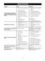
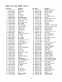
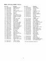
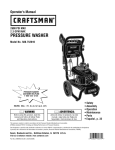
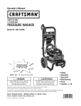
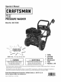
CRAFTSMAN 3800 PSI Pressure Washer 580.752382
Main Unit -- Exploded View and Parts List
8® 88r\'\\\
8 @_fg@ /
-- 9
14
7
/
I¢_Pc>9 :
Item
1
2
3
4
5
6
7
8
9
10
Part #
313328GS
313192BTGS
205734GS
196233GS
195983AGS
195983BGS
1959830GS
195983DGS
195846ZZGS
195294GS
192132GS
312774GS
189971GS
203046GS
208673GS
63281GS
95458GS
J
Description
BASE
HANDLE
HOSE
KIT-QCNOZZLES
NOZZLE-QCRED
NOZZLE-QCYELLOW
NOZZLE-QCGREEN
NOZZLE-QCWHITE
NOZZLE-QCBLACK
KIT-HRDWRENGINEMOUNTING
KIT-PUMP MOUNTINGHARDWARE
WHEEL
HOSE-CHEMICAL
PUMP
VALVE-THERMALRELIEF
KEY
FITTING
Item
11
12
13
14
15
900
Part #
199310GS
199956GS
193814GS
203040GS
192310GS
NSP
Items Not Illustrated
Part#
313955GS
191267RGS
30809GS
AB3061BGS
208538GS
209697GS
205687GS
194256GS
OptionalAccessories
7175187
Garden Hose Quick Connect
7175197
Accessory Quick Connect
7175124
Rotating Brush Kit
7175122
30' Replacement Hose
7175116
0 Ring Repair Kit
7175129
Turbo Nozzle
7175121
25' Extension Hose
7174402
Hose Reel
7174403
Pump Saver
7174404
Project Pro@PerfectMiWMMulti-Purpose and Vehicle Cleaner
7174405
Project Pro@PerfectMiWMConcrete, Brick, and Tile Cleaner
7174406
Project Pro@PerfectMiWMMold and Mildew Cleaner
26
Description
ADAPTER-GARDENHOSE
GUN
EXTENSION-QC
KIT-HARDWAREHANDLE
MOUNT-VIBRATION
ENGINE(GX390T2)(see pages28-33)
Description
MANUAL-OPERATOR'S
AXLE
GROMMET
OIL
DECAL-Warning
DECAL-MaxPSI
DECAL-Shroud
TAG-WARNING
CRAFTSMAN 3800 PSI Pressure Washer 580.752382
Pump -- Exploded View and Parts List
L
oL
@
@
g
÷
O--
L
@
0
--A
@
50--1
o
%
O
H
o
C
E
H
H
2O
\
O
E
J
F
L
@
©
Item
20
25
34
50
66
83
A
B
C
D
E
F
G
H
Part#
198851GS
204860GS
198850GS
198849GS
198297GS
203034GS
198736GS
202799GS
198844GS
192914GS
198845GS
198848GS
198852GS
198846GS
|
0
0
Item
J
K
L
L
@
g
O0
0
Description
INJECTOR-DETERGENT
JET
PLUG
DIPSTICK
SCREW
PLUG-DRAIN
KIT-UNLOADER
KIT-CHECKVALVE
KIT-PISTON
KIT-CHEMICALINJ
KIT-WATERSEAL
KIT-SUPPORTRING
KIT-HARDWARE
KIT-OIL SEALS
@
g
Part#
198847GS
202902GS
202800GS
o
Description
KIT-O-RING
KIT-UNLOADERSEAT
KIT-UNLOADER
NOTE:Item letters A - L are service kits and include all parts
shown within the box.
PartsNotlllustrated
B2384GS
FILTER-GARDENHOSE
208673GS
VALVE-THERMALRELIEF
OptionalAccessories
7174403
PUMP SAVER
6033
OIL
27
ENGINE, 13 HP, Honda, GX390T2 - Exploded View
1
10
11
(__
17
\\
13
4
2
27 28
34
1
36
._./
I
43
28
ENGINE, 13 HP, Honda, GX390T2 - Exploded View
5O
56
1
55
62
63
7O
76
20
ENGINE, 13 HP, Honda, GX390T2 - Exploded View
79
81
©
84
87
85
94
1 O2
lOO
104
105
99
i
111
112_
_108
109
_6
69
6
113
10
115
6
61
114
7_
2
122
123 _1
Ii__)
120
30
__1_
ENGINE, 13 HP, Honda, GX390T2 - Exploded View
-\
34
132
128
129
140
_-141
135
152
148 -130 --
153
160
--
154
155
?
5
159
162
158
161
163
156
175
170
171
174
2
172
31
ENGINE, 13 HP, Honda, GX390T2 - Parts List
Item
1
2
3
4
5
6
7
8
9
10
11
12
13
14
15
16
17
18
19
20
21
22
23
24
25
26
27
28
29
30
31
32
33
34
35
36
37
38
39
40
41
42
43
44
45
46
47
48
49
50
51
52
53
Part #
16010-ZE2-812
90013-883-000
91201-ZLC-003
91353-671-003
94050-06000
94050-08000
96100-62020-00
90014-Z5T-O00
90441-ZE2-010
12310-Z5T-O00
12391-ZE2-020
95701-10080-00
12357-Z5T-O00
12216-ZE2-300
12205-ZE2-305
12204-ZE2-306
12210-Z5T-406
92900-08032-0E
98079-56846
12251-Z5T-O03
94301-12200
90042-ZE8-000
95701-06012-00
94050-10000
35480-ZF6-003
12000-Z5T-407
94109-12000
90131-896-650
90446-KE1-000
94251-10000
16541-ZE3-010
91203-952-771
16959-Z5T-901
95701-08040-00
15625-ZOT-800
15600-ZOT-820
15600-Z10-000
96100-62070-00
94101-06800
16510-ZE3-000
90602-ZE1-000
16531-ZOA-O00
11300-Z10-600
11381-Z5T-O00
90701-H04-000
31110-Z5T-O00
90741-ZE2-000
19511-ZE3-000
28451-ZE3-W01
90201-ZE3-790
90745-ZE2-600
13351-ZE3-010
13310-ZF6-W12
Item
54
55
56
57
58
59
60
61
62
63
64
65
66
67
68
69
70
71
72
73
74
75
76
77
78
79
80
81
82
83
84
85
86
87
88
89
90
91
92
93
94
95
96
97
98
99
100
101
102
103
104
105
106
Description
GASKETSET
BOLT, FLANGE
OIL SEAL
O-RING
NUT, FLANGE
NUT, FLANGE
BEARING,RADIAL BALL
BOLT, HEADCOVER
WASHER, HEADCOVER
COVER,HEAD
GASKET,HEADCOVER
BOLT, FLANGE
TUBE, BREATHER
CLIP,VALVE GUIDE
GUIDE,EX.VALVE
GUIDE,VALVE
CYLINDERHEAD
BOLT,STUD
SPARK PLUG
GASKET,CYLINDERHEAD
PIN, DOWEL
BOLT,STUD
BOLT, FLANGE
NUT, FLANGE
SWITCHASSY., OIL LEVEL
CYLINDERASSY
WASHER, DRAIN PLUG
BOLT, DRAIN PLUG
WASHER
PIN, LOCK
SHAFT,GOVERNORARM
OIL SEAL
FILTER,CUP
BOLT, FLANGE
GASKET,OIL FILLERCAP
CAPASSY
CAPASSY
BEARING,RADIAL BALL
WASHER
GOVERNORASSY
CLIP, GOVERNORHOLDER
SLIDER, GOVERNOR
COVERASSY
GASKET,CASECOVER
PIN, DOWEL
FLYWHEEL
KEY
FAN,COOLING
PULLEY,STARTER
NUT, SPECIAL
KEY
WEIGHT,BALANCER
CRANKSHAFT
32
Part#
91001-ZF6-013
13010-Z5R-O04
90601-ZE3-000
13101-Z5T-800
13111-Z5T-O00
90001-ZE8-000
13200-Z10-000
90202-Z2E-O00
14751-Z10-000
14775-ZE2-010
14721-Z5T-O00
14711-Z5T-O00
14771-Z8S-O00
14771-Z8S-O00
12209-ZE8-003
90004-Z5T-O00
14100-Z5T-810
14568-ZE1-000
90206-ZE1-000
14451-ZE1-013
14431-ZE2-010
90012-ZE0-010
14791-Z1D-O00
14410-Z10-000
14441-ZE2-000
17510-Z5T-OOOZA
17631-ZOT-801
17620-Z4H-020
95701-08025-00
28463-Z5T-O03
16854-ZH8-000
95002-40800-08
91424-Z5T-O03
16955-ZE1-010
90004-ZE2-W01
28444-ZE2-W01
28441-ZE2-W01
28422-ZE2-W01
28443-ZE2-W01
28421-ZE3-W01
28442-ZE2-W01
28410-ZE3-WO1ZB
28461-Z5T-O03
28462-ZE3-W01
90008-ZE2-003
28400-Z5T-OO3ZB
90006-ZE2-000
90050-ZE1-000
18320-Z5T-O00
18336-ZE3-000
18310-Z5T-O00
18350-Z5T-800
18381-ZE2-W10
Description
BEARING,RADIAL BALL
RINGSET, PISTON
CLIP, PISTONPIN
PISTON
PIN, PISTON
BOLT,CONNECTINGROD
RODASSY
NUT,AIRCLEANERCOVER
SPRING,VALVE
SEAT,VALVE SPRING
VALVE,EX.
VALVE, IN.
RETAINER,EX.VALVE SPRING
RETAINER,IN. VALVESPRING
SEAL,VALVE STEM
SCREW,TAPPING
CAMSHAFTASSY
SPRING,WEIGHT RETURN
NUT, PIVOT
PIVOT,ROCKERARM
ARM, VALVE ROCKER
BOLT, PIVOT
PLATE,PUSH RODGUIDE
ROD,PUSH
LIFTER,VALVE
TANK, FUEL
GASKET,FUELFILLERCAP
CAP,FUEL FILLER
BOLT,FLANGE
GRIP, REINFORCEMENT
RUBBER,SUPPORT
CLAMP,TUBE
TUBE,FUEL
JOINT, FUELTANK
SCREW,CENTER
RETAINER,SPRING
SPRING, FRICTION
RATCHET,STARTER
SPRING, RATCHET
PULLEY,RECOILSTARTER
SPRING, STARTERRETURN
CASE,RECOILSTARTER
GRIP,STARTER
ROPE,RECOILSTARTER
BOLT,FLANGE
STARTERASSY
SCREW,TAPPING
SCREW,TAPPING
PROTECTOR,MUFFLER
FLANGE,BAFFLE
MUFFLER
ARRESTER,SPARK
GASKET,MUFFLER
ENGINE, 13 HP, Honda, GX390T2 - Parts List
Item
107
108
109
110
111
112
113
114
115
117
118
119
120
121
122
123
124
125
126
127
128
129
130
131
132
133
134
135
136
137
138
139
140
141
142
Part #
18205-Z5T-000
18381-ZE2-800
18331-Z5T-000
18333-ZF6-W01
35120-Z5T-003
16731-ZE2-003
19631-Z5T-000
19610-Z5T-000ZB
90325-044-000
17232-891-000
17210-ZE3-505
17218-ZE3-505
17231-Z5T-000
17235-Z5T-000
17417-Z5T-000
90009-Z10-000
17239-ZE1-000
17238-ZE2-310
17410-Z5T-000
16212-Z5T-000
16211-Z5T-000
16221-Z5T-000
16100-Z5T-901
16172-ZE3-W10
99204-ZE0-0380
94305-20122
16610-ZE1-000
16016-ZH7-W01
16124-ZE0-005
16044-Z5T-901
93500-03006-0H
16954-ZE1-812
16956-ZE1-811
16953-ZE1-812
16173-001-004
143 16957-ZE1-812
144 16967-ZE0-811
Description
PROTECTOR,EX. PIPE
GASKET,MUFFLER
PIPE, EX.
GASKET,EX.PIPE
SWITCHASSY, ENGINESTOP
CLIP,TUBE
SHROUD
COVER,FAN
NUT, TOOLBOXSETTING
GROMMET,AIR CLEANER
ELEMENT,AIR CLEANER
FILTER
COVER,AIR CLEANER
NOSE,MUFFLER
GASKET,ELBOW
BOLT-WASHER
COLLARB, AIR CLEANER
COLLAR,AIR CLEANER
ELBOW,AIR CLEANER
GASKET,INSULATOR
INSULATOR,CARBURETOR
GASKET,CARBURETOR
CARBURETORASSY
COLLAR,SETTING
JET SET, PILOT
PIN, SPRING
LEVER,CHOKE
SCREWSET, PILOT
SCREW,THROTTLESTOP
CHOKESET
SCREW,PAN
PLATE,LEVERSETTING
SPRING, PETCOCKLEVER
LEVER,PETCOCK
*GASKET,FUELSTRAINER
CUP
*GASKET,PETCOCK
CUP,FUELSTRAINER
Item
145
146
147
148
149
150
151
152
153
154
155
Part #
16166-Z5T-901
16011-ZA0-931
99101-ZH8-1050
16013-Z10-003
16015-Z5T-901
16028-Z5T-901
16024-Z5T-901
16220-ZA0-702
30700-Z1C-811
30500-Z5T-003
32110-Z5T-000
156
157
158
159
160
161
162
163
164
165
166
167
168
169
170
171
172
173
31512-ZE2-000
90015-883-000
90684-ZA0-601
16561-ZE3-000
16562-ZE3-000
16555-ZE3-000
90015-Z5T-000
16551-ZE3-000
90114-SA0-000
16575-ZE2-W00
16574-ZE1-000
16592-883-310
16578-ZE1-000
16571-ZE3-W00
93500-05016-0A
16576-891-000
16580-Z5T-000
16584-883-300
174
175
176
177
178
93500-05032-0A
16500-Z5T-810
16511-ZE8-000
16512-ZE3-000
16513-ZE2-000
Description
NOZZLE,MAIN
VALVESET, FLOAT
JET, MAIN
FLOATSET
CHAMBERSET, FLOAT
SCREWSET
SCREWSET,DRAIN
SPACER,CARBURETOR
CAPASSY
COIL ASSY
WIRE HARNESSASSY.,
ENGINE
GROMMET,WIRE
BOLT,FLANGE
CLIP, HARNESS
SPRING, GOVERNOR
SPRING,THROTTLERETURN
ROD,GOVERNOR
BOLT,GOVERNORARM
ARM, GOVERNOR
NUT, SELF-LOCK
WASHER,CONTROLLEVER
SPRING, LEVER
SPRING, CABLERETURN
SPACER,CONTROLLEVER
LEVER,CONTROL
SCREW,PAN
HOLDER,CABLE
BASE,CONTROL
SPRING, CONTROL
ADJUSTING
SCREW,PAN
CONTROLASSY
WEIGHT,GOVERNOR
HOLDER,GOVERNORWEIGHT
PIN, GOVERNORWEIGHT
* - INCLUDEDIN CARBURETORGASKETSET
33
California, U.S. EPA, and Sears Emissions
Control Warranty Statement
Sears EmissionsControlWarranty Provisions
The following are specific provisions relative to your
Emissions Control Warranty Coverage. It is in addition to the
Searsengine warranty for non-regulated engines found in
the Operator's Manual.
1. Warranted Emissions Parts
Coverageunder this warranty extends only to the parts
listed below (the emissions control systems parts) to
the extent these parts were present on the engine
purchased.
YourWarranty RightsAnd Obligations
The California Air Resources Board, U.S. EPA,and Sears
Brands ManagementCorporation, U.S.A. (Sears) are pleased
to explain the emissions control system warranty on your
Model Year 2008 and later engine/equipment. In California,
new small off-road engines must be designed, built, and
equipped to meet the State's stringent anti-smog standards.
Sears must warrant the emissions control system on your
engine/equipment for the periods of time listed below
provided there has been no abuse, neglect, or improper
maintenance of your small off-road engine.
a.
Your emissions control system may include parts such as
the carburetor or fuel injection system, fuel tank, ignition
system, and catalytic converter. Also included may be hoses,
belts, connectors, sensors, and other emissions-related
assemblies. Where a warrantable condition exists, Sears will
repair your engine/equipment at no cost to you including
diagnosis, parts, and labor.
b.
Fuel Metering System
•
Cold start enrichment system (soft choke)
•
Carburetor and internal parts
•
Fuel pump
•
Fuel line, fuel line fittings, clamps
•
Fueltank, cap and tether
•
Carbon canister
Air Induction System
Manufacturer'sWarranty Coverage:
•
Air cleaner
Small off-road engines are warranted for two years. If any
emissions-related part on your engine/equipment is
defective, the part will be repaired or replaced by Sears.
•
Intake manifold
•
Purge and vent line
c.
Owner's Warranty Responsibilities:
•
As the small engine/equipment owner, you are
responsible for the performance of the required
maintenance listed in your owner's manual. Sears
recommends that you retain all receipts covering
maintenance on your engine/equipment, but Sears
cannot deny warranty solely for the lack of receipts or
your failure to ensure the performance of all scheduled
maintenance.
d.
e.
As the engine/equipment owner, you should however be
aware that Sears may deny you warranty coverage if
your engine/equipment or a part has failed due to abuse,
neglect, improper maintenance, or unapproved
modifications.
2.
You are responsible for presenting your
engine/equipment to a Sears distribution center,
servicing dealer, or other equivalent entity, as applicable,
as soon as a problem exists. The warranty repairs
should be completed in a reasonableamount of time,
not to exceed 30 days. If you have any questions
regarding your warranty rights and responsibilities, you
should contact Sears at (800) 469-4663.
Ignition System
•
Spark plug(s)
•
Magneto ignition system
Catalyst System
•
Catalytic converter
•
Exhaust manifold
•
Air injection system or pulse valve
Miscellaneous Items Used in Above Systems
•
Vacuum, temperature, position, time sensitive
valves and switches
•
Connectors and assemblies
Length of Coverage
For a period of two years from date of original purchase,
Searswarrants to the original purchaser and each
subsequent purchaser that the engine is designed, built,
and equipped so as to conform with all applicable
regulations adopted by the Air Resources Board; that it
is free from defects in material and workmanship that
could cause the failure of a warranted part; and that it is
identical in all material respects to the engine described
in the manufacturer's application for certification. The
warranty period begins on the date the engine is
originally purchased.
In the USA and Canada,a 24-hour hotline, 1-800-469-4663, has a menu of pre-recorded messages offering you product maintenance
information.
34
Thewarranty
onemissions-related
partsisasfollows:
LookFor Relevant EmissionsDurability Period and Air
• Anywarranted
partthatis notscheduled
forreplacement Index InformationOnYour Engine EmissionsLabel
asrequired
maintenance
intheowner's
manual
supplied, Enginesthat are certified to meet the California Air Resources
iswarranted
forthewarranty
periodstated
above.
If any Board (CARB) Emissions Standard must display information
suchpartfailsduringtheperiodofwarranty
coverage, regarding the Emissions Durability Period and the Air Index.
thepartwillberepaired
orreplaced
bySears
atnocharge The engine manufacturer makes this information availableto
totheowner.
Anysuchpartrepaired
or replaced
under
the consumer on emissions labels. The engine emissions
thewarranty
willbewarranted
fortheremaining
warranty label will indicate certification information.
period.
The EmissionsDurability Period describes the number of
• Anywarranted
partthatis scheduled
onlyforregular
hours of actual running time for which the engine is certified
inspection
intheowner's
manual
supplied,
iswarranted to be emissions compliant, assuming proper maintenance in
forthewarranty
periodstatedabove.
Anysuchpart
accordance with the Operating & Maintenance Instructions.
repaired
or replaced
underwarranty
willbewarranted
for The following categories are used:
theremaining
warranty
period.
Moderate: Engine is certified to be emissions compliant for
• Anywarranted
partthatisscheduled
forreplacement
as
125 hours of actual engine running time.
required
maintenance
intheowner's
manual
supplied,
is
Intermediate: Engine is certified to be emissions compliant
warranted
fortheperiod
oftimepriortothefirstscheduledfor
250 hours of actual engine running time.
replacement
pointforthatpart.Ifthepartfailspriortothe
Extended:
Engine is certified to be emissions compliant for
firstscheduled
replacement,
thepartwillberepaired
or
500
hours
of actual engine running time.
replaced
bySears
atnocharge
totheowner.
Anysuchpart
repaired
or replaced
underwarranty
willbewarranted
for
For example, a typical walk-behind lawn mower is used 20 to
theremainder
oftheperiod
priortothefirstscheduled
25 hours per year. Therefore, the EmissionsDurability
replacement
pointforthepart.
Period of an engine with an intermediate rating would
• Addonor modified
partsthatarenotexempted
bytheAir equate to 10 to 12 years.
Resources
Board
maynotbeused.Theuseofanynon
Small off-road engines are certified to meet the United States
exempted
addonormodified
partsbytheownerwillbe
Environmental Protection Agency (USEPA) Phase2
grounds
fordisallowing
awarranty
claim.The
emissions standards. For Phase 2 certified engines, the
manufacturer
willnotbeliabletowarrant
failures
of
Emissions Compliance Period referred to on the Emissions
warranted
partscaused
bytheuseofanonexempted
add Compliance label indicates the number of operating hours for
onormodified
part.
which the engine has been shown to meet Federalemissions
3. Consequential
Coverage
requirements.
For engines less than 225 cc displacement.
Coverage
shallextend
tothefailureofanyengine
Category C = 125 hours
components
caused
bythefailureofanywarranted
Category B = 250 hours
emissions
parts.
CategoryA = 500 hours
4. Claims
andCoverage
Exclusions
For engines of 225 cc or more displacement.
Warranty
claimsshallbefiledaccording
tothe
Category C = 250 hours
provisions
oftheSears
engine
warranty
policy.
Warranty Category B = 500 hours
coverage
doesnotapplytofailures
ofemissions
parts
CategoryA = 1000 hours
thatarenotoriginal
equipment
Sears
partsortoparts
thatfailduetoabuse,
neglect,
orimproper
maintenance
assetforthintheSears
engine
warranty
policy.
Sears
is
notliableforwarranty
coverage
offailures
ofemissions
partscaused
bytheuseofadd-on
ormodified
parts.
35
GARANTIA
.....................................
36
CONTRATO
DEPROTECCION
PARA
REPARACIONES
......... 36
REGLAS
DESEGURIDAD
.......................
37-39
CARACTER/STICAS
YCONTROLES
..................
40
MONTAJE
...................................
41-43
OPERACION
.................................
44-48
ESPECIFICACIONES
.............................
49
MANTENIMIENTO
............................
49-54
ALMACENAMIENTO
...........................
55-56
REPARACION
DEDANOS
REPUESTOS
...............
57
GARANTIA
DELCONTROL
DEEMISIONES
......... 58-59
COMO
ORDENAR
PARTES
......... PAGINA
POSTERIOR
GARANTIALIIVIITADADE DOS A IOS DE CRAFTSMAN
DURANTEDOSAMOSa partir de lafecha de compra, este producto cuenta con una garantia contra cualquier defecto material o de mano de
obra. Los productos defectuosos ser_n reparados sin costo alguno, o bien, ser_n sustituidos en caso de que no sea posible repararlos.
Para conocer los detalles de cobertura de la garantia sobre c6mo obtener reparaci6n o sustituci6n sin costo, visite el sitio web:
www.craftsman.com
Esta garantia no cubre las pistolas rociadoras, mangueras, prolongadores de boquilla, boquillas, filtros y bujias, ya que son recambios que
pueden desgastarsecon el uso normal dentro del periodo de garantia.
Esta garantia se invalida si este producto se utiliza alguna vez para prestar servicios comerciales o si se renta a otra persona.
Esta garantia le otorga determinados derechos legales yes posible que tenga otros derechos que pueden variar de una provincia a otra.
Sears Brands Management Corporation, Hoffman Estates, IL 60179
Felicidadespor realizar una compra inteligente.
Una vez que adquiera el contrato de protecci6n para reparaciones,
s61otiene que hacer una sencilla Ilamada telef6nica para programar
un servicio. Puede Ilamar a cualquier hora del dia o la noche, o
programar una cita de servicio en linea.
Su nuevo producto Craftsman® est_ diseSado y fabricado para
funcionar de manera fiable durante muchos aSos. Pero como todos
los productos, es posible que requiera reparaci6n ocasionalmente.
Es en esos momentos, tener un contrato de protecci6n para
reparaciones puede ahorrarle dinero y molestias.
El contrato de protecci6n para reparacioneses una compra segura.
Si Io cancela por cualquier motivo durante el periodo de garantia del
producto, le reembolsaremos el total de su dinero o una parte
proporcional en cualquier momento posterior al vencimiento del
periodo de garantia del producto. Adquiera hoy su contrato de
protecci6n para reparaciones.
A continuaci6nse menciona Io que el contrato de protecci6npara
reparaciones* contempla:
•
Servicio experto de nuestros 10.000 especialistas profesionales
en reparaci6n.
•
Servicio ilimitado y sin costoen partes y mano de obra en
todas las reparaciones incluidas en la cobertura.
•
Cambio del producto por hasta $1.500 si el producto incluido
en la cobertura no se puede reparar.
•
Un 10% de descuento en el precio normal de servicio yen
partes instaladas relacionadas no incluidas en la cobertura del
contrato; asimismo, un 10% de descuento en el precio normal
de revisiones de mantenimiento preventivo.
•
Aplican algunas limitaciones y exclusiones. Para conocerprecios
y obtener informaci6nadicional en EE. UU., Ilame al
1-800-827-6655.
* Lacobertura
en Canaddvaria endeterminados
articulos.Para
obtenertodoslosdetalles,comuniquese
a SearsCanaddal
1-800-361-6665.
Serviciode instalaci6ndeSears
Para solicitar un servicio de instalaci6n por parte de un profesional
de Sears para aparatos dom_sticos, puertas autom_ticas de garajes,
calentadores de agua y otros articulos dom_sticos importantes en
EE. UU. o Canada,comuniquese al 1-800-4-MY-HOME®.
Ayudatelef6nica r_pida. Nuestro servicio de Soluci6n r_pida
consiste en apoyo telef6nico por un representante de Sears.
Piense que somos un "manual del usuario parlante".
36
_i, ADVERTENCIA El escape del motor de este producto
contiene elementos quimicos reconocidos en el Estado de
California por producir c_.ncer,defectos de nacimiento u
otros da_os de tipo reproductivo.
Lea
estemanualminuciosamente
y conozca
a fondolas
partes
y el funcionamiento
desum_quina
limpiadora
a
presi6n.Conozcasusaplicaciones,
suslimitaciones
y los
peligrosinvolucrados.
Informaci6nimportantede seguridad
_i, ADVERTENCIA Este producto contiene plomo y
compuestos de plomo declarados causantes de
malformaciones y otros defectos cong6nitos por el Estado
de California. Ldvese las manos despu_s de manipular
este producto.
Simbolossobre la seguridady significados
Manualdel Operario
GasesT6xicos
DescargaEI6ctrica
_i_ ADVERTENCIA AI motor funcionar, se produce
mon6xido de carbono, un gas inodoro y venenoso.
_La
inhalaci6n de mon6xido de carbono puede
provocar lesiones graves, dolor de cabeza,
fatiga, mareos, v6mitos, confusi6n, convulsiones,
n_.useas, desmayos o incluso la muerte.
La inhalaci6n o ingesti6n de algunas sustancias quimicas
o detergentes puede ser peligroso y provocar lesiones
graves, n_.useas, desmayos, envenenamiento o la muerte.
SuperficiesResbalosas Inyecci6nLiquida Partesen Movimiento
• Utilice este producto SOLOa la intemperie.
Caer
SuperficieCaliente
Proyectil
• Aseg0resede que los gases de escape no puedanentrar por
ventanas, puertas, tomas de aire de ventilaci6n u otras
aberturas en un espacio cerrado en el que puedanacumularse.
ObjetosVoladores
• NO utilice este producto en el interior de un edificio, cochera,
porche, equipo m6vil, taller de aplicaciones navaleso recinto,
aunque haya ventanasy puertas abiertas.
Explosi6n Quemadura
Quimica Contragolpe
• Utilice un respirador o una m_scara cada vez que exista la
posibilidad de inhalar vapores al utilizar sustancias quimicas.
_i, El simbolo de alerta de seguridad indica un posible
riesgo para su integridad fisica. Se utiliza una palabra de
se_alizaci6n (PELIGRO,ADVERTENCIAo PRECAUCION)
junto con el simbolo de alerta para designar un grado o
nivel de gravedad de riesgo. Se puede utilizar un simbolo de
seguridad para representar el tipo de riesgo. La palabra de
se_alizaci6nAVISO se utiliza para hacer referencia a una
pr_.cticano relacionadacon una lesi6n fisica.
_i, PELIGROindica un riesgo que, de no evitarse, provocar#
la muerte o lesiones de gravedad.
• Leatodas las instrucciones de la m_.scarapara comprobar si
proporciona la protecci6n necesariacontra la inhalaci6n de
vapores nocivos cuando se utilicen sustancias quimicas.
_i, ADVERTENCIAindica un riesgo que, de no evitarse,
podrfa provocar la muerte o lesiones de gravedad.
_i_ ADVERTENCIA Peligro de quemadura quimica.
r...... Lassustanciasquimicaspodrian provocar
_
quemaduras,asi como da_os materiales,lesiones
graves o incluso la muerte.
• NOuseliquidoc_usticoconla limpiadoraa presi6n.
• UseEXCLUSIVAMENTE
detergentes
o jabonesespeciales
parala
limpiadoraa presi6n.Sigatodaslasinstrucciones
del fabricante.
Fuego
,&, ADVERTENCIA Riesgo de electrocuci6n.
'_,llh El contacto con los cables el6ctricos podria
provocar electrocuci6n y quemaduras que
pueden provocar lesiones graves o la muerte.
• NUNCArociecercade unafuentede energiael_ctrica.
_i, PRECAUCIONindica un riesgo que, de no evitarse, podrfa
provocar lesiones leves o moderadas.
AFISO hace referencia a una pr_.cticano relacionada con una
lesi6n fisica.
37
_i_ ADVERTENCIA El combustible y sus vapores son
extremadamenteinflamablesy explosivos,
A ADVERTENCIA El retroceso (repliegue r_.pido) del
cable del arrancador impedir_, que el usuario
_,_,_
suelte el cable a tiempo y tirar_, de su mano y
Tbrazo hacia el motor, Io que podria provocar
fracturas, contusiones o esguinces; asi como lesiones
g raves.
• NUNCAtire del cable del arrancador sin eliminar previamente la
presiCn de la pistola rociadora.
Io que podria provocar quemaduras,
incendioso explosiones;asi como da_os
materiales,lesiones graveso incluso la muerte.
CUANDO
ANADACOMBUSTIBLE
0 VACIEELDEPOSITO
• DETENGAel motor del limpiadora a presiCny dCjeloenfriar
durante al menos 2 minutos antes de quitar el tapCn de
combustible. Afloje la tapa lentamente para dejar que la presiCn
salga del tanque.
• Cuando arranque el motor, tire lentamente del cable hasta
sentir una resistenciay, a continuaciCn,tire r_pidamente de 61
para evitar su retroceso.
• Llene o vacie el depCsito de combustible a la intemperie.
• Despu_s de cada intento de arranque, cuando el motor no
consiga arrancar, apunte con la pistola rociadora hacia una
direcciCn segura, pulse el botCnrojo y apriete el gatillo para
descargar la presiCn.
• Sujete firmemente la pistola rociadora con ambas manos
cuando aplique un rociado a alta presiCn para evitar lesiones
cuando se produzca el retroceso de la pistola.
• NO Ilenedemasiado eltanque. Permita al menos espacio para
la expansiCndel combustible.
• Si se ha derramado combustible, esperea que se evapore antes
de arrancar el motor.
• Mantenga la gasolina alejada de chispas, llamas abiertas,
pilotos, calory otras fuentes de igniciCn.
• Compruebe frecuentemente que las lineas de combustible, el
tanque, el tapCn y los accesorios no estCn rotos o tengan fugas.
C_mbielos si es necesario.
,&. ADVERTENCIA
Los gases y el calor de escape
podrian inflamar los materiales
combustibles Y las estructuras o da_ar
el depCsito de combustible y provocar
incendios, asi como da_os materiales, lesiones graves o
incluso la muerte.
El contacto con la zona del silenciador podria producir
quemaduras y lesiones graves.
• NO toque las superficies calientes y EVITElos gasesdel escape
a alta temperatura.
• NO encienda un cigarrillo o fume.
CUANDOPONGAEN FUNCIONAMIENTOELEQUIPO
• Compruebe que la bujia, el silenciador, el tapCn del depCsito de
combustible y el filtro de aire est_n instalados.
• NO arranque el motor sin la bujia instalada.
CUANDOOPEREELEQUIPO
• NO utilice este producto en el interior de un edificio, cochera,
porche, equipo mCvil,taller de aplicaciones navaleso recinto.
• NO incline el motor o el equipo, de tal manera que la gasolina
se puedaderramar.
• NO rocie liquidos inflamables.
AL TRANSPORTAR,MOVER0 REPARAREQUIPO
• Permita que el equipo se enfrie antes de tocarlo.
• Deje un espacio minimo de 1.5 m (5 pies) alrededor del
limpiadora a presiCn, incluida la parte superior.
• Utilizar el motor en un terreno boscoso, con maleza o cubierto
de hierba constituye una infracciCnal CCdigode recursos
pt_blicosde California, a menos que el sistema de escape est_
equipado con una pantalla apagachispas,de acuerdo a la
definiciCn de la SecciCn4442, que se mantenga en buenas
condiciones de funcionamiento. En otros estados o
jurisdicciones federales puede haber leyes similares en vigor.
PCngaseen contacto con el fabricante, el vendedor o el
distribuidor del equipo original para obtener una pantalla
apagachispasdise_ada para el sistema de escape instalado en
este motor.
• Transporte, mover o repare el equipo con el tanque de
combustible vacio, o con lav_lvula para apagar el combustible,
apagada (posiciCn OFF).
• NO incline el motor o el equipo, de tal manera que la gasolina
se puedaderramar.
• Desconecteel cable de la bujia.
CUANDOALMACENE0 GUARDEELEQUIPOCONCOMBUSTIBLE
EN ELTANQUE
Mant_ngalo alejado de calderas, estufas, calentadores de agua,
secadoras de ropa u otros aparatos que utilicen llama piloto u
otras fuentes de igniciCn que podrian inflamar los vapores de
combustible.
• Las piezas de recambio debenser las mismas que las piezas
originales y estar instaladas en la misma posiciCn.
_i_ ADVERTENCIA
,&. ADVERTENCIA
El uso de una limpiadora a presiCn
El arrancador y otras piezas rotativas
,_
podria producir
resbaladizas
quecharcos
provoquen
y superficies
que se caiga
y sufra lesiones graves o que se muera.
El retroceso de la pistola rociadora podria provocar caidas
con lesiones graves o la muerte.
• Utilice la limpiadora a presiCndesde una superficie estable.
podrian
u
otros accesorios,
enredarse en
y provocar
las manos,lesiones
el pelo,graves.
la ropa
• NUNCAutilice la limpiadora a presiCn sin sus carcasas o tapas
de protecciCn.
• NO utilice ropa suelta, joyas ni objetos que podrian quedar
atrapados en el arrancador o en otras piezas rotativas.
%
• El _rea de limpieza deber_ tener inclinaciones y drenajes
adecuados para disminuir la posibilidad de caidas debido a
superficies resbalosas.
• Ate para arriba el pelo largo y quite la joyeria.
• Extreme las precaucionessi necesita utilizar la limpiadora a
presiCn desde una escalera, un andamio u otro lugar similar.
• Sujete firmemente la pistola rociadora con ambas manos
cuando aplique un rociado a alta presiCn para evitar lesiones
cuando se produzca el retroceso de la pistola.
38
,&. PRECAUCION Las velocidades de funcionamiento
excesivamentealtas podrian provocar lesiones leves y/o
da_os al limpiadora a presi6n.
Lasvelocidades excesivamente bajas incrementan la
carga de trabajo.
• NOintentealterarel resorte,lasconexionesy otras partesdel
reguladorparaincrementarla velocidaddel motor.La
limpiadoraa presi6nejercela presi6ny el flujo nominales
correctoscuandofuncionaa unavelocidadcontrolada.
_i, ADVERTENCIA El chorro de agua a alta presi6n que
este equipo produce podria atravesar la piel y
los tejidos subcut_.neos, que podrian provocar
lesiones graves y la posible amputaci6n de un
miembro.
La pistola rociadora retiene agua a alta presi6n incluso
con el motor parado y el agua desconectada; esto podria
provocar lesiones graves.
• En caso de que algOnliquido le cause una cortadura, Ilameal
m_dico de inmediato. NO latrate como unacortadura comOn.
• NOmodifiqueal limpiadoraa presi6nen ningunaforma.
• NO permita en ningOn momento que NINOS operen la m_quina
limpiadora a presi6n.
• NUNCArepare la manguera de alta presi6n. Remplacela.
AVlSO El rociado de alta presi6n podria da_ar objetos
fr_.giles, incluido el vidrio.
• NUNCAutilice ningOntipo de sellador para reparar unafuga en
una conexi6n. Sustituya la junta t6rica o la junta.
• NO dirija la pistola rociadora hacia un cristal cuando utilice la
punta de rocio de roja de 0°.
• NUNCAapunte la pistola a plantas.
• NUNCAconecte la manguera de alta presi6n al prolongador de
la boquilla.
• Mantenga conectada la manguera a la m_quina o a la pistola de
rociado cuando el sistema est_ presurizado.
• SIEMPREque pare el motor, apunte con la pistola rociadora
hacia una direcci6n segura, pulse el bot6n rojo y apriete el
gatillo para descargar la presi6n.
AVISO Un tratamiento inadecuado de la limpiadora
presi6n podria da_arla y acortar su vida t_til.
• NUNCAapunte la pistola a la gente, animales o plantas.
a
• Si usted tiene alguna pregunta acerca de las finalidades de uso del
limpiadora a presi6n, pregOntelea su concesionario o contacte el
distribuidor de servicio autorizado.
• NO fije la pistola rociadora en la posici6n abierta.
• NO abandone la pistola rociadora cuando la m_quina est_ en
funcionamiento.
• NUNCAdeber_n ser operadas las unidades con partes rotas o
ausentes, o sin la caja o cubiertas de protecci6n.
• NUNCAutilice una pistola rociadora cuyo seguro o protecci6n
para el gatillo no est_ en perfecto estado de funcionamiento.
• NO eluda ning0n dispositivo de seguridad de esta m_quina.
• NO intente alterar la velocidad controlada.
• AsegOreseen todo momento de conectar correctamente la
pistola rociadora, las boquillas y los accesorios.
• NO utilice la limpiadoraa presi6npor encimade su presi6n nominal.
,&. ADVERTENCIA Las chispas involuntarias podrian
"_ilh provocar incendios o electrocuci6n que
pueden provocar lesiones graves o la
muerte.
CUANDO
AJUSTE
0 HAGAREPARACIONES
A SUIVlAQUINA
LIIVlPIADORA
A PRESION
• NO haga ninguna modificaci6n en la limpiadora a presi6n.
• Siempredesconecteel alambrede la bujiay col6quelodonde
no puedaentraren contactocon la bujia.
CUANDO
PRUEBE
LABUJIADELMOTOR
• El equipo de alta presi6n est_ dise_ado para ser utilizado
UNICAMENTEcon las partes autorizadasSears. Si utiliza este
equipo con partes que no cumplan con las especificaciones
minimas, el usuario asume todos los riesgos y responsabilidades.
• Antes de poner en marcha la m_quina limpiadora a presi6n en
clima frio, revise todas las partesdel equipo y asegOresede que
no se hayaformado hielo sobre elias.
• NUNCAmueva la m_quina halando la manguera de alta presi6n.
Utilice la manija que viene con la unidad.
• Utilice un comprobador de bujias homologado.
• NO comprueba la chispa sin la bujia instalada.
_i, ADVERTENCIA
Riesgo de lesiones en los ojos o el
cuerpo.
El
agua rociada podria salpicar o
propulsar objetos, Io que puede
provocar lesiones graves.
• Cuando utilice este equipo o est_ cerca de 61,siempre use gafas
de seguridad con ventilaci6n indirecta (contra salpicaduras de
productos quimicos) marcadas para cumplir con ANSI Z87.1.
• NUNCAse ponga gafas de seguridad ni gafas para entornos
secos como sustituto de las gafas de seguridad con ventilaci6n
indirecta.
• Siempre utilice ropa de protecci6n como una camisa de manga
larga, pantalones largos y zapatos cerrados.
• NUNCAponga en funcionamiento la limpiadora a presi6n
cuando est6 descalzo, Ileve sandalias o pantalones cortos.
39
CONOZCASU IVIAQUINA
LIMPIADORAA PRESION
___.
Lea el Manual
del Operario
laslimpiadora
reglas de seguridadantes
de poner encon
marcha
su limpiadora
a presi6n.
Compare
las ilustraciones
cony su
a presi6n para familiarizarse
las ubicaciones
de los
diferentes controles y ajustes.
Guarde este manual para referencias futuras.
®
Ponga el interruptor en la posici6n "Off" (Apagado) para parar el
motor cuando est_ funcionando.
A - Manguera de alta presi6n -- Conecte un extremo a la pistola
de rociado y el otro extremo a la toma de alta presi6n.
B - Puntas de rocio-- Detergente, 0°, 15°, 25°, 40°: para diferentes
aplicaciones de limpieza de alta presi6n.
N - Palanca del acelerador -- Activa el modo de arranque del
motor para poder utilizar el arrancador de retroceso.
C - Filtro de aire -- El elemento de filtro tipo seco limita la cantidad
de suciedad y polvo que se introduce en el motor.
P - Tanque de combustible-- Llene el tanque con gasolina regular
sin contenido de plomo en este punto. Siempre deje el espacio
suficiente como para que el combustible se expanda.
D - Toma de alta presi6n -- Conexi6n para la manguera de alta
presi6n.
R - Extensi6npara boquillas con conexi6nr_ipida-- Le permite
usar cinco puntas de rocio diferentes.
E - Etiquetade advertencia e instrucciones --Identifica los
riesgos e indica el procedimiento adecuado de arranque o
parada de la limpiadora a presi6n.
S - Pistolade rociado conconexi6n r_ipida-- Controla la
aplicaci6n de agua sobre la superficie de limpiezacon el gatillo.
Incluyecerrojo de seguridad.
No mostrado:
F - Bomba -- Suministra agua a alta presi6n.
G - Sistema de enfriamiento autom_itico -- Cuando el agua
alcanza los 51°-68° C (125°-1550 F), el sistema se activa y enfria
la bomba descargandoagua caliente en el piso. Este sistema
evita que el interior de la bomba se dane.
Entradade agua -- Conexi6n para la manguera de jardin.
H - Palanca estranguladora -- Enfria el motor para arrancarlo.
Etiquetade datos(parle trasera cercanaa la placa de base) -Proporciona el modelo y el nOmero de serie de la limpiadoraa
presi6n. Tenga estos datos a la mano cuando solicite ayuda.
J - V_ilvulade combustible-- Se utiliza para abrir y cerrar la
alimentaci6n de combustible al motor.
Perilla de control de la presi6n -- Varia la presi6n de rociado de la
presi6n.
K - Tap6nde Vaciado de Aceite -- Permitevaciar el aceitedel motor.
Tap6n de Ilenado de aceile/varilla de nivel -- Compruebe aqui el
nivel de aceite y a_adaaceite cuando sea necesario.
L - Arrancador de retroceso -- Se utiliza para arrancar
manualmente el motor.
Tubo/liltro de inyecci6n de delergenle -- Oselo para inyectar el
detergente con seguridad en el circuito de baja presi6n.
M - Interruptorde arranque -- Ponga el interruptor en la posici6n
"On" (Encendido) para realizar un arranque por retroceso.
40
Sum_quina
limpiadora
apresi6n
requiere
decierto
ensamble
y
6.
estarA
listapara
serusada
t_nicamente
despu6s
dehaber
depositado
elcombustible
yelaceite
recomendado.
7.
Sitieneproblemasconel ensambledesum_quinalimpiadoraa
8.
presi6n,Ilamea la lineadeayudade la m_quinalimpiadoraa
presi6nal 1-800-222-3136.
9.
Desembalela limpiadoraa presi6n
1.
Saque todo el contenido de la caja de cart6n, a excepci6n de la
limpiadora a presi6n.
2.
Abra completamente la caja de cart6n cortando cada una de
sus esquinas de arriba abajo.
3.
Saque la limpiadora a presi6n de la caja de cart6n.
Conecte la manguera de alta presi6n a la pistola de rociado y a
la bomba.
Conecte el suministro de agua a la bomba.
Conecte boquilla la extensi6n al pistola rociadora.
Selecto/conecta r_pido conecta boquilla a la extensi6n de la
boquilla.
Fijar el asa
1.
Coloque el asa (B) sobre los soportes del asa (C) que ya se
encuentran conectados a la unidad principal. Asegt_resede que
los orificios en el asa (D) est6n alineados con los orificios en
los soportes del asa (D).
Contenidode la caja
Revise el contenido de la caja. Si alguna de las partes no est_
presente o est_ da_ada, Ilame a la linea de ayuda de la m_quina
limpiadora a presi6n al 1-800-222-3136.
• La unidad principal
• Asa
•
•
La manguera de alta presi6n
Pistola de rociado
•
•
Extensi6n de la lanza con las piezas de conexi6n r_pida
Aceite para motor
AVISO Tal vez sea necesario mover los soportes del asa de un
lado a otro para alinear el asa de tal manera que pueda deslizarse
sobre los soportes del mismo asa.
•
Bolsa de accesorios (incluye Io siguiente):
2.
Inserte el perno del soportes (E) a trav6s del orificios del asa y
fije la perillas de pl_stico (F). Apriete la perillas manualmente.
3.
Inserte las puntas de rociado multicolores en los espacios
provistos en la asa.
•
Manual del propietario
•
Tarjeta de registro del propietario
•
Bolsa con 5 lanzas de conexiones r_pidas multicolores
•
Piezas para la asa (incluye Io siguiente):
•
Perno del Soporte (2)
•
Perilla Pl_stica (2)
Familiaricese con cada parte antes de ensamblar la m_quina
limpiadora a presi6n. Compare el contenido con la ilustraci6n de la
p_gina 40. Si alguna de la partes NO est,. presente o se encuentra
da_ada, Ilame a la linea de ayuda de la m_quina limpiadora a
presi6n al 1-800-222-3135.
MONTAJE DE LA IVIAQUINALIMPIADORA A
PRESION
Agregueaceite de motor
La gran mayoriade su m_quinalimpiadora a presi6n Craftsman ha
sido ensambladaen laf_brica. Sin embargo, usted deber_.Ilevara
cabo los siguientes procedimientosantes de poner en funcionamiento
su m_quina limpiadora a presi6n:
1. Llene y mande en tarjeta de matricula.
2.
Fijar el asa.
3.
Deposite aceite en la caja del cig_Je_aldel motor.
4.
Deposite combustible en el tanque.
5.
Verifique la varilla para el aceite (A) es instale en la bomba.
1.
Coloque la limpiadora a presi6n en una superficie plana y
nivelada.
2.
Limpie la zona de alrededor del orificio de Ilenado de aceite y
quite el tap6n.
3.
Con la ayuda de un embudo (opcional), vierta lentamente el
contenido de las dos botellas de aceite por el orificio de
Ilenado hasta el punto de desbordamiento.
AVISO El tratamiento inadecuado del limpiadora a presi6n
puede da_arlo y acortar su vida productiva.
• NO procure acodar ni empezar el motor antes ha sido atendido a
apropiadamente con el aceite recomendado. Esto podria provocar
una averia en el motor.
4.
41
Vuelva a colocar el tap6n y apri6telo firmemente.
3.
Agreguegasolina
_i_ADVERTENCIA El combustible y sus vapores son
extremadamenteinflamablesy explosivos,
iPRECAUCION! Los combustibles con mezcla de alcohol (gasohol,
etanol o metanol) pueden atraer la humedad y provocar la
separaci6n y formaci6n de _cidos durante el almacenamiento. Los
gases_cidos pueden dafiar el circuito de combustible y el motor
durante el almacenamiento.
_._
Io que podria provocar quemaduras,
incendios o explosiones;asi como da_os
materiales,lesiones graveso incluso la muerte.
CUANDO
ANADACOMBUSTIBLE
ELDEPOSITO
Para evitar este tipo de problemas, vacie el circuito de combustible
cuando vaya a almacenar la unidad durante 30 dias o m_s. Vacie el
dep6sito de combustible, arranque el motor y d_jelo funcionar hasta
que los conductos de combustible y el carburador queden vacios.
Utilice combustible nuevo la pr6xima temporada. Para obtener m_s
informaci6n al respecto, consulte Almacenamiento.
• DETENGAel motor del limpiadora a presi6n y d_jelo enfriar
durante al menos 2 minutos antes de quitar el tap6n de
combustible. Afloje la tapa lentamente para dejar que la presi6n
salga del tanque.
• Llene el dep6sito de combustible a la intemperie.
• NO Ilenedemasiado el tanque. Permita al menos espacio para
la expansi6n del combustible.
NUNCAutilice productos limpiadores para motores o carburadores
en el dep6sito de combustible, ya que podrian provocar dafios
permanentes.
• Si se ha derramado combustible, esperea que se evapore antes
de arrancar el motor.
Lubrique las juntas t6ricas
• Mantenga la gasolina alejada de chispas, llamas abiertas,
pilotos, calor y otras fuentes de ignici6n.
La lubricaci6n de las juntas t6ricas es extremadamente importante
para la instalaci6n y operaci6n. El uso de un lubricante (petr61eoo
grasa sint_tica) durante el montaje es de utilidad para que las juntas
t6ricas se asienten adecuadamentey el sellado quede mejor.
Tambi_n ayuda a proteger la junta t6rica contra da_os por abrasi6n,
pinchazos o cortes, y extiende su duraci6n.
• Compruebefrecuentemente que las lineas de combustible, el
tanque, el tap6n y los accesorios no est6n rotos o tengan fugas.
O_mbielossi es necesario.
• NO encienda un cigarrillo o fume.
.
Utilice gasolina normal sin plomo, limpia y nueva con un
minimo de 86 octanos. NO mezcle aceite con combustible.
2.
Limpie el _.reaalrededor de latapa de Ilenadodel combustible,
retire la tapa.
3.
Agregue lentamente gasolina regular "SIN PLOMO"al tanque de
combustible. Use un embudo para evitar que se derrame. Llene
el tanque lentamente hasta aproximadamente 1" por debajo de
la parte la cima del cuello del tubo de Ilenado.
Nivel m_ximo de combustible
Instale la tapa del tanque de combustible y la espera para
algOn combustible rociado para evaporar.
AVISO SIEMPREaplique una peque_a cantidad de lubricante en
las juntas t6ricas antes de montar la manguera de jardin a la entrada
de agua de la bomba (A), manguera a alta presi6n a la salida de alta
presi6n de la bomba (B), manguera a alta presi6n (C), la pistola
rociadora (D), y el prolongador de la boquilla (E).
Lubriquetodas las conexionesse muestra a continuaci6n,
siguiendo estas instrucciones:
42
1.
Revisey limpie las superficies de conexi6n antes de la
lubricaci6n y el montaje.
2.
Utilice los lubricantes con moderaci6n durante el montaje; s61o
se requiere una capa ligera.
3.
Cuando no tenga acceso alas juntas t6ricas, utilice un cepillo
peque_o o torunda de algod6n para aplicarles la grasa
directamente (adaptador QC,adaptador M22).
Conectela mangueray el suministrode agua a
la bomba
4.
AVI$O NO haga funcionar la bomba si no tiene el
suministro conectado y abierto.
• El daSoa la limpiadoraa presi6n,resultadode la desatenci6n
a
estaprecauci6n,no ser&cubiertopor la garantia.
AVI$O Hace NO agua de parar de siphon para el abastecimiento de
agua. Useagua SOLOfria (menos que 100°F).
AVISO El uso de una v_.lvulaunidireccional (igualador de
presi6n o v_.lvulade retenci6n) en la entrada de la bomba
podria producir daSos en la bomba o en el conector de
entrada.
• DEBEhaberun minimode 3 metros(10 pies)de manguerade
riegolibreentrela entradade la limpiadoraa presi6ny cualquier
dispositivo,como un igualadorde presi6no unav&lvulade retenci6n).
• EldaSoa la limpiadoraa presi6n,resultadode la desatenci6n
a
estaprecauci6n,no ser&cubiertopor la garantia.
AVI$O Antes de conectar las mangueras, retire y deseche los
tapones de transporte de la salida de alta presi6n y de la entrada de
agua de la bomba.
1.
Haga correr el agua a trav_s de la manguera de su jardin por
30 segundos para limpiar cualquier escombro que se
encuentre en ella. Desconecteel agua.
Retroceda la manguera a alta presi6n y conecte el extremo de
la conexi6n r_pida de la manguera a la base de la pistola
rociadora. Hale el collar de la conexi6n r_pida, deslicelo en la
pistola rociadora y suelte el collar. H_lelo en la manguera para
asegurarse de que este conectado firmemente.
5.
Conecte la manguera de jardin (no exceder 50 pies en la
Iongitud) a la entrada del agua. Apriete con la mano.
_tk ADVERTENCIA Riesgo de lesiones oculares.
El agua rociada podria salpicar o propulsar
objetos, Io que puede provocar lesiones graves.
• Cuando utilice este equipo o est6 cerca de 61,siempre use gafas
de seguridad con ventilaci6n indirecta (contra salpicaduras de
productos quimicos) marcadas para cumplir con ANSI Z87.1.
• NUNCAse ponga gafas de seguridad ni gafas para entornos
secos como sustituto de las gafas de seguridad con ventilaci6n
indirecta.
ADVERTENClA El chorro de agua a alta presi6n que
este equipo produce podria atravesar la piel y
los tejidos subcut_neos, que podrian provocar
lesiones graves y la posible amputaci6n de un
miembro.
• NUNCAconectela manguerade altapresi6nal prolongadorde
la boquilla.
• Mantengaconectadala mangueraa la m_quinao a la pistolade
rociadocuandoel sistemaest_presurizado.
• Asegt_rese
entodo momentode conectarcorrectamente
la
pistolarociadora,lasboquillasy los accesorios.
,
,
6.
De la misma manera, conecte el otro extremo de la manguera a
alta presi6n, a la salida de alta presi6n (A) de la bomba. Hale el
collar de la conexi6n r_pida, deslicelo en la bombay suelte el
collar. Hale la manguera para asegurarse que esta bien
conectada.
ABRA el agua, apunte con la pistola hacia una direcci6n segura
presione el seguro (bot6n rojo) (C) y apriete el gatillo para
eliminar el aire y las impurezas del sistema de bombeo.
Lista de revisionprevia al arranquedel motor
Revise la unidad para asegurarse que ha Ilevadoa cabo los
siguientes procedimientos:
Antes de que conecte la manguera de jardin a la entrada de
agua, inspeccioneel colador de la entrada (B). Limpie el colador
si tiene residuos o solicite su remplazo si est_ da_ado. NO haga
funcionar la limpiadora a presi6nsi el filtro de entrada falta
o est_i daNado.
43
1.
Asegt_resede leer las secciones Reglas de Seguridady
OperaciSnantes de usar el limpiadora a presi6n.
2.
Cerci6rese el asa es seguro.
3.
Asegt_resede que el tap6n de transporte se ha quitado y de
que la varilla de nivel de aceite se ha instalado en la bomba.
4.
Revise que haya sido depositado aceite y est_ al nivel correcto
en la caja del cig_JeSaldel motor.
5.
Deposite la gasolina adecuada en el tanque del combustible.
6.
Revise quetodas las conexiones de las mangueras (alta
presi6n y suministro de agua) est_n apretadas correctamente y
que no existan dobleces, cortes o daSo de la manguera de alta
presi6n.
7.
Proporcione el suministro de agua adecuado (que no exceda
los IO0°F).
COIVIOUSARSU IVIAQUINA
LIIVIPIADORA
A
PRESION
C6mo darle arranque a su mdquina limpiadora a
presi6n
Para darle arranque a su m_.quinalimpiadora a presi6n movida a
motor por primera vez, siga estas instrucciones paso a paso. Esta
informaci6n acerca del arranque inicial tambi_n se aplica cuando
vaya a darle arranque al motor despu_s de haber dejado de la
m_quina limpiadora a presi6nn fuera de uso por al menos un dia.
Si tiene problemas con el funcionamiento de su m_quina limpiadora
a presi6n, por favor Ilame a la linea de ayuda de la m_quina
limpiadora a presi6n al 1-800-222-3136.
Ubicaci6n del limpiadora a presi6n
1.
Coloque la m_quina limpiadora a presi6n en un _rea cercanaa
una suministro de agua exterior capaz de abastecer agua a un
volumen mayor de 5.0 galones por minuto en no menos que
20 PSI en el fin de arandela de presi6n de la manga del jardin.
2.
Revise que la manguera de alta presi6n se encuentre
conectada firmemente a la pistola de rociado y a la bomba. Vea
Montaje.
3.
Aseg0rese que la unidad est_ nivelada.
4.
Conecte la manguera de jardin a la entrada del agua. Aprietela
con la mano.
Espaciolibrealrededordel limpiadoraa presi6n
_i_ ADVERTENCIA
Los gases y el calor de escape
podrfan inflamar los materiales
_
combustibles Y las estructuras 0 dafiar
el dep6sito de combustible y provocar
incendios, asf como dafios materiales, lesiones graves 0
incluso la muerte.
• Deje un espacio minimo de 1.5 m (5 pies) alrededor del
limpiadora a presi6n, incluida la parte superior.
Coloque la limpiadora a presi6n a la intemperie en una zona en
donde no se acumulen gases de escape mortales. Aseg0resede que
los gases de escape (A) no puedan entrar por ventanas, puertas,
tomas de aire de ventilaci6n u otras aberturas en un espacio
cerrado en el que puedan acumularse. Tenga en cuenta los vientos y
las corriente de aire preponderantes cuando elija la ubicaci6n del
limpiadora a presi6n.
AVISO NO haga funcionar la bomba si no tiene el
suministro conectado y abierto.
• Eldafioa la limpiadoraa presi6n,resultadode la desatenci6n
a
estaprecauci6n,no ser_cubiertopor la garantia.
Abra el agua, apunte con la pistola hacia una direcci6n segura
presione el seguro (bot6n rojo) y apriete el gatillo para eliminar
el aire y las impurezas del sistema de bombeo.
5.
_i_ ADVERTENCIA AI motor funcionar, se produce
mon6xido de carbono, un gas inodoro y venenoso.
_La
inhalaci6n de mon6xido de carbono puede
provocar lesiones graves, dolor de cabeza,
fatiga, mareos, v6mitos, confusi6n, convulsiones,
n_.useas, desmayos 0 incluso la muerte.
.
Acople la boquilla de extensi6n a la pistola aspersora. Apri_tela
manualmente.
• Utilice este producto SOLOa la intemperie.
• Aseg0rese de que los gases de escape no puedan entrar por
ventanas, puertas, tomas de aire de ventilaci6n u otras aberturas en un espacio cerrado en el que puedan acumularse.
• NO utilice este producto en el interior de un edificio, cochera,
porche, equipo m6vil, taller de aplicaciones navaleso recinto,
aunque haya ventanasy puertas abiertas.
7.
Seleccione la puntas de rocio de conexi6n r_pida que usted
deseee ins_rtela en el extremo de la extensi6n de la lanza.Vea
Como Usar las Puntas de Rocfo.
8.
SitOe la palanca de la vfilvula de combustible (B) en la posicidn
"Encendido"("On").
OFF
44
9.
12. Cuando arranque el motor, col6quese en la posici6n que se
Sitt_ela palanca del acelerador (A) en la posici6n "R_pido"
("Fast"), que se distingue con la figura de un conejo.
recomienda a continuaci6n. Sujete la manija y hale ligeramente
la manija del arranque hasta que sienta cierta resistencia.
Despu_s h_lela r_pidamente.
10. Mueva la perilla del cebador (B) a la posici6n "Cerr6"("Closed").
/ ....
\
,/
//
"
,[
)PEN
CLOSED
AI!ISO En el caso de que el motor est_ caliente, aseg_resede que
la perilla del cebador se encuentre en la posici6n "Abra" ("Open").
11. Sitt]e el interruptor de arranque (C) en la posici6n "On"
(Encendido).
E
_i_ ADVERTENClA
El retroceso (repliegue r_.pido) del
cable del arrancador impedir_t que el usuario
,_
suelte el cable a tiempo y tirar_, de su mano y
brazo hacia el motor, Io que podria provocar
fracturas, contusiones o esguinces; asi como lesiones
graves.
• NUNCAtire del cable del arrancador sin eliminar previamente la
presi6n de la pistola rociadora.
OFF
• Cuando arranque el motor, tire lentamente del cable hasta
sentir una resistenciay, a continuaci6n, tire r_pidamentede _1
para evitar su retroceso.
• Despu_sde cadaintento de arranque, cuando el motor no
consiga arrancar, apunte con la pistola rociadora hacia una
direcci6n segura, pulse el bot6n rojo y apriete el gatillo para
descargar la presi6n.
• Sujete firmemente la pistola rociadora con ambas manos
cuando aplique un rociado a alta presi6n para evitar lesiones
cuando se produzca el retroceso de la pistola.
13. Jale la cuerda de arranque lentamente.NO permita que la cuerda
regrese bruscamenteen contra del arrancador.
AI/ISO Antes de arrancar la limpiadora a presi6n, asegt_resede
ponerse gafas de seguridad como se describe a continuaci6n.
14. Cuando arranque el motor, mueva lentamente la perilla del
cebador a la posici6n "Abra"("Open"). Si el motor falla, mueva
la perilla del cebador a la posici6n "Cerr6"("Closed"), y despu_s
a la posici6n "Abra" ("Open").
_i_ADVERTENClA Riesgo de lesiones oculares.
El agua rociada podria salpicar o propulsar
objetos, Io que puede provocar lesiones graves.
15. Si los fuegos de motor, pero no contint]a correr, siempre
se_alar elfusil en la direcci6n segura, presione el seguro
(bot6n rojo) y el disparador del fusil del rocio del estruj6n para
liberar la presi6n alta. Mueva la perilla del cebador a la posici6n
"Abra"("Open"),y repite los pasos 12 por 14.
• Cuando utilice este equipo o est_ cerca de _1,siempre use gafas
de seguridad con ventilaci6n indirecta (contra salpicaduras de
productos quimicos) marcadas para cumplir con ANSI Z87.1.
• NUNCAse ponga gafas de seguridad ni gafas para entornos
secos como sustituto de las gafas de seguridad con ventilaci6n
indirecta.
16. Si el motor no arranca despu_s de 6 tirones, mueva la perilla
del cebador a la posici6n "Abra" ("Open"), y repite los pasos
12 por 14.
AI!ISO Siempre mantenga la palanca del acelerador en el "R_pido"
("Fast") posicione cu_ndo operar la arandela de la presi6n.
45
C6mo detenersu m quina limpiadoraa presi6n
_i_ADVERTENCIA El chorro de agua a alta presiCn que
este equipo produce podrfa atravesar la piel y
los tejidos subcut_.neos,que podrfan provocar
lesiones graves y la posible amputaciCn de un
miembro.
La pistola rociadora retiene agua a alta presiCn incluso
con el motor parado y el agua desconectada;esto podrfa
provocar lesiones graves.
• NOpermitaen ningOnmomentoqueNINOSoperenla m_quina
limpiadoraa presi6n.
• Mantengaconectadala mangueraa la m_quinao a la pistolade
rociadocuandoel sistemaest_presurizado.
1.
Espere que el motor descanse.
2.
SitOe la palanca del acelerador en la posici6n "Slow" (Lento),
indicada con una tortuga.
3.
Mueva la interruptor de arranque a la posici6n"Off"("Lejos").
4.
SitOe la palanca de la v_lvula de combustible en la posici6n
"Off"("Lejos").
_i_ ADVERTENClA El combustible y sus vapores son
extremadamente inflamables y explosivos,
10que podrfa provocar quemaduras,
incendios 0 explosiones; asf como da_os
materiales, lesiones graves 0 incluso la muerte.
• NO coloque la palanca estranguladora en la posici6n "Choke"
para parar el motor.
• NUNCAapuntela pistolaa la gente,animaleso plantas.
• NOfije la pistolarociadoraen la posici6nabierta.
• NOabandonela pistolarociadoracuandola m_quinaest_en
funcionamiento.
5.
• NUNCAutilice una pistola rociadora cuyo seguro o protecci6n
para el gatillo no est_ en perfecto estado de funcionamiento.
• AsegOreseen todo momento de conectar correctamente la
pistola rociadora, las boquillas y los accesorios.
SIEMPREfusil de punto en una direcci6n segura, presione el
seguro (bot6n rojo) y el disparador del fusil del rocio del
estruj6n para liberar la presi6n retenida de la pleamar.
,&, ADVERTENClA El chorro de agua a alta presiCn que
este equipo produce podrfa atravesar la piel y
los tejidos subcut_.neos,que podrfan provocar
lesiones graves y la posible amputaciCn de un
miembro.
La pistola rociadora retiene agua a alta presiCn incluso
con el motor parado y el agua desconectada; esto podrfa
provocar lesiones graves.
• Mantengaconectadala mangueraa la m_quinao a la pistolade
rociadocuandoel sistemaest_presurizado.
• SIEMPRE
que pareel motor,apuntecon la pistolarociadora
baciaunadirecci6nsegura,pulseel bot6nrojo y aprieteel
gatilloparadescargarla presi6n.
_i_ ADVERTENCIA
Los gases y el calor de escape
podrfan inflamar los materiales
combustibles Y las estructuras 0 da_ar
el depCsito de combustible y provocar
incendios, asf como da_os materiales, lesiones graves 0
incluso la muerte.
El contacto con la zona del silenciador podrfa producir
quemaduras y lesiones graves.
• NO toque las superficies calientes y EVITElos gasesdel escape
a alta temperatura.
• Permita que el equipo se enfrie antes de tocarlo.
• Deje un espacio minimo de 1.5 m (5 pies) alrededor del
limpiadora a presi6n, incluida la parte superior.
• Utilizar el motor en un terreno boscoso, con maleza o cubierto
de hierba constituye una infracci6n al C6digo de recursos
pOblicos de California, a menos que el sistema de escape est_
equipado con una pantalla apagachispas,de acuerdo a la
definici6n de la Secci6n4442, que se mantenga en buenas
condiciones de funcionamiento. En otros estados o
jurisdicciones federales puede haber leyes similares en vigor.
P6ngaseen contactocon elfabricante,elvendedoro el distribuidor
del equipo original para obtener unapantallaapagachispas
dise_adapara el sistemade escapeinstaladoen este motor.
• Las piezas de recambio debenser las mismas que las piezas
originales y estar instaladas en la misma posici6n.
46
C6mousar las puntas de rocio
Limpiezay aplicaci6ndel detergente
La extensi6n para boquillas de conexi6n r_pida le permite usar cinco
puntas de rocio diferentes. Siempre que est_ activado el seguro del
gatillo de la pistola rociadora, se pueden cambiar las puntas de rocio
con la limpiadora a presi6n en funcionamiento. Las puntas de rocio
tienen diferentes patrones de rociado como se ilustra a continuaci6n.
,& ADVERTENCIA Peligro de quemadura quimica.
_
quemaduras,asi
as sustanciasquimicaspodrian
como daSosmateriales,lesiones
provocar
graves o incluso la muerte.
• NOuseliquidoc_usticoconla limpiadoraa presi6n.
• UseEXCLUSIVAMENTE
detergentes
o jabonesespeciales
parala
limpiadoraa presi6n.Sigatodaslasinstrucciones
del fabricante.
Para cambiar las puntasde rocio:
1. Desplace hacia atr_s el anillo de conexi6n r_pida y tire de las
puntas de rocio. Guarde las puntas de rocio en el soporte
situado en el asa.
Para aplicar el detergente, siga los siguientespasos:
,& ADVERTENCIA El chorro de agua a alta presi6n que
este equipo produce podria atravesar la piel y
los tejidos subcut_.neos,que podrian provocar
lesiones graves y la posible amputaci6n de un
miembro.
• NUNCAintercambiepuntasde rociosin haberaseguradoel
cerrojode seguridaddel gatillo.
• NOtuerzapuntasde rocioal rociar.
.
Para enjuague suave, seleccione la punta de rocio blanca
de 400o verde de 25°.
•
Para fregar la superficie, seleccione la punta de rocio
amarilla de 15° o roja de 0°.
•
.
Prepare la soluci6n detergente siguiendo las instrucciones del
fabricante.
3.
Coloque el extremo pequeSo del filtro del tubo de inyecci6n de
detergente dentro del contenedor del detergente.
AVISO El contacto con el silenciador a alta temperatura
podria producir daSos en el tubo de inyecciOn de detergente.
• Cuando coloque el filtro en la botella del detergente, coloque el
tubo de manera que no entre en contacto accidentalmente con el
silenciador caliente.
4.
Para aplicar productos detergentes, seleccione la punta de
rocio negra.
Aseg_rese de que la puntas de rocio negra est6 instalada en la
extensi6n para boquillas.
AVlSO NO se puede aplicar detergente con las puntas de rocio de
alta presi6n (Blanca,Verde, Amarilla o Roja).
5. Asegt_resede que la manguera del jardin est_ conectada a la
entrada de agua. Compruebe que la manguera de alta presi6n
est_ conectada a la pistola rociadora y a la bomba. Abra la
alimentaci6n de agua.
Desplace hacia atr_s el anillo, inserte la nueva punta de rocio y
suelte el anillo. Tire de la punta de rocio para comprobar que
est_ bien montada.
Sugerencias de uso
•
Revise el uso de las puntas de rocio.
2.
AVISO Asegt_resede que el filtro est6 totalmente sumergido
mientras aplica el detergente.
Seleccione la punta de rocio deseada:
•
1.
Para una limpieza m_.sefectiva, mantenga la boquilla de rociado
de 20 a 61 cm (8 a 24 pulgadas) de la superficie de limpieza.
•
Si coloca la boquilla de rociado demasiado cerca podria da5ar la
superficie, especialmente cuando est_ usando el modo de alta
presi6n.
AVlSO Usted deber_t conectar todas las mangueras antes
de darle arranque al motor.
• Si pone en marcha el motor sin haber conectado previamente
todas las mangueras y sin haber ABIERTOel grifo, la bomba
podria averiarse.
•
NO coloque la boquilla a menos de 15 cm (6 pulgadas) cuando
est_ limpiando Ilantas.
• El da_o a la limpiadora a presi6n, resultado de la desatenci6n a
esta precauci6n, no ser_ cubierto por la garantia.
La Presi6n Alta
La Presi6n
Baja Usada
para aplicar
quimicos
i
i
i
Negra
i
i
i
400
Blanca
i
250
Verde
47
i
i
i
150
Amarilla
00
Roja
6.
Marcha el motor siguiendo las instrucciones de la secci6n
C6mo poner en funcionamiento la limpiadora a presi6n.
Limpieza del tube de inyecci6nde detergente
7.
Aplique el detergente sobre la superficie seca, comenzando en
la parte inferior del Areay dirigi_ndose hacia arriba, utilizando
movimientos largos, parejos y superpuestos.
1.
Coloque el filtro y la inyecci6n de detergente en un balde Ileno
de agua limpia.
8.
Permita que el detergente penetre de 3 a 5 minutes antes de
enjuagar. Vuelva a aplicar cuando sea necesario para evitar que
la superficie se seque. NO permita que el detergentese seque.
Si permite que el detergente se seque, la superficie podria
quedar con manchas.
2.
Quite la punta de rocio de alta presi6n del prolongador de la
boquilla.
3.
Seleccione e instale la punta de rocio negra (detergente)
siguiendo las instrucciones de la secci6n C6mo usar las puntas
de rocio.
Si us6 el tube, debe lavarlo con agua limpia antes de parar el motor.
.
AVI$O Usted deberA lavar el sistema de inyecci6n de quimicos
despu_s de cada use colocando el filtro en un balde de agua limpia
y haciendo funcionar la mAquina limpiadora a presi6n de 1 a 2
minutes en el mode de baja presi6n.
5.
.
Enjuagede la m quina limpiadora a presi6n
Para Enjuage:
1.
,
3.
Seleccione e instale la punta de rocio de alta presi6n que desee
siguiendo las instrucciones de C6mo usar las puntas de rocfo.
Mantenga la pistola de rociado a una distancia segura del Area
que planea rociar.
El retroceso de la pistola rociadora
muerte.
podria provocar caidas con lesiones graves o la
• Utilice la limpiadora a presi6n desde una superficie estable.
• Extreme las precaucionessi necesita utilizar la limpiadora a
presi6n desde una escalera, un andamio u otro lugar similar.
Aumente (disminuya) la presi6n de rociado al darle vuelta a la
perilla (A) en la direcci6n de las manecillas del reloj (en
direcci6n opuesta). Use una presi6n mAs baja para lavar cosas
come carros o botes. Use una presi6n mAs alta para eliminar
pintura y grasa de calzadas.
5.
Aplique un rociado de alta presi6n en un Area pequeSa,
despu6s revise si la superficie presenta daSos. Si no encuentra
daSos, puede continuar con el trabajo de limpieza.
6.
Comience en la parte superior del Area que va a enjuagar,
dirigi6ndose hacia abajo con los mismos movimientos
superpuestos que utiliz6 para la limpieza.
SIEMPRE apunte la pistola rociador hacia una direcci6n
segura, oprima el bot6n rojo y apriete el gatillo de la pistola
rociadora para liberar la presi6n.
Sistema de enfriamiento autom_tico (alivio
t6rmico)
• Sujete firmemente la pistola rociadora con ambas manes
cuando aplique un rociado a alta presi6n para evitar lesiones
cuando se produzca el retroceso de la pistola.
.
Pare el motor siguiendo las instrucciones de la secci6n CSmo
detener su limpiadora a presiSn y cierre la entrada de agua.
,&, ADVERTENClA El chorro de agua a alta presi6n que
este equipo produce podria atravesar la piel y
los tejidos subcut_.neos,que podrian provocar
lesiones graves y la posible amputaci6n de un
miembro.
La pistola rociadora retiene agua a alta presi6n incluso
con el motor parade y el agua desconectada; esto podria
provocar lesiones graves.
• Mantengaconectadala mangueraa la mAquinao a la pistolade
rociadocuandoel sistemaest_presurizado.
• SIEMPRE
que pareel motor,apuntecon la pistolarociadora
haciaunadirecci6nsegura,pulseel bot6nrojo y aprieteel
gatilloparadescargarla presi6n.
Retire la punta de rocio negra para detergente de la extensi6n
para boquillas.
_i_ ADVERTENClA
Lavede 1 a 2 minutes.
El agua que circula dentro de la bomba puedealcanzartemperaturas
entre los 125°-155°F si hace funcionar el motor de su mAquina
limpiadora a presi6n de 3 a 5 minutes sin oprimir el gatillo de la
pistola de rociado. El sistema de enfriamiento automAtica se activa a
esta temperatura y enfria la bomba descargando agua caliente en
el pise, evitande asi el dafie interne de la bemba.
48
RESPONSABILIDADES
DELPROPIETARIO
ESPECIFICACIONESDEL PRODUCTO
Siga el programa de mantenimiento seg_n el nt_merode horas o
seg_n el calendario, Io que suceda primero. Se requiere de servicio
con mayor frecuencia cuando opere la unidad en las condiciones
adversas descritas a continuaci6n.
Especificaciones de la mdquina limpiadora a
preslon
Presi6n .......................................
3,800 PSI*
Velocidad de flujo ................................
4,0 GPM
Mezcla de quimicos ..................
Use segt_ninstrucciones
Temperatura del suministro
de agua ............................
Que no exceda los IO0°F
Plan de mantenimiento
•
Cambie el aceite del motor
•
Revise/limpie el filtro de la entrada de agua1
13 a 3600 rpm
•
Revisela manguera de alta presi6n
Di_metro de camisa ....................
88 mm (3,5 pulgadas)
•
Revisela manguera del detergente
Carrera ..............................
64 mm (2,5 pulgadas)
•
Revisela pistola aspersora y verifique que no haya
fugas en el ensamblaje
•
Limpie los residuos
NGK BPR6ES
•
Compruebe el filtro de aire
0,028-0,031 pulgadas
(O,70-O,80mm)
•
Compruebe el nivel de aceite
•
Limpie el filtro de aire2
•
Cambiar el aceite del motor
•
Limpie el recipiente para sedimentos
•
Compruebe y ajuste la bujia
•
Servicio al sistema de la bujia1
•
Limpie el dep6sito de combustible y elfiltro
•
Cambio del aceite de la bomba_
Capacidadde la bomba de aceite ..............
0.35 I (12 fl. oz.)
Especificacionesdel motor
Caballos de Fuerza ...........................
Desplazamiento .......................
389 cc (23,7 pulgadas)
Bujia
Resistor: ..................................
Calibrar Separaci6n a: .................
Admisi6n .........................
0,15 mm _+0,02 mm (frio)
Escape ..........................
0,20 mm _+0,02 mm (frio)
Capacidadde Gasolina .........................
1.72 galones
Tipo de Aceite ................................
SAE 10W-30
* Esta limpiadora a presi6n est_ clasificada conforme a la norma
PWl01 (comprobaci6n y clasificaci6n de rendimiento de
limpiadoras a presi6n) de laAsociaci6n de fabricantes de bombas
a presi6n (Pressure Washer Manufacturers Association, PWMA).
_
a_
•
Sustituya el filtro de aire3
•
Sustituya la bujia
•
Compruebe y ajuste el ralentP
•
Compruebe y ajuste de holgura de las v_lvulas4
....
....
•
Limpie la c_mara de combusti6n4
•
Compruebe el tubo de combustible (sustituirsi es
necesario)4
Limpiar si est_ obstruido. Remplazar si est9 perforado o roto.
49
2
Sustitt_yalo con m_s frecuencia en condiciones de suciedad o polvo.
3
Sustituya t_nicamente el elemento de papel.
4
Para reparar estos elementos, acuda al servicio t6cnico de su distribuidor.
s
Cambie el aceite despues de las primeras 50 horas de funcionamiento y luego,
cada 200 horas o 3 meses, Io que suceda antes.
Recomendacionesgenerales
Revisey limpie el coladorde entrada
El mantenimiento peri6dico mejorar_ el rendimiento y prolongar_ la
vida 0til del limpiadora a presi6n. Si necesita asistencia, consulte
con un distribuidor de Sears o con otro distribuidor cualificado.
Examine el colador de entrada de la manguera de jardin. Limpielo si
est_ tapado o remplacelo si est_ roto.
Revise la manguerade alta presi6n
La garantiade la m_quina limpiadora a presi6n NOcubre los
elementos que hansido sujetos a abuso o negligenciapor parte del
operador. Parahacer v_lida la cobertura total de lagarantia, el
operador deber_ mantener la lavadorade presi6ntal y como se indica
en el manual,incluyendo su adecuadoalmacenamiento,como se
describeen la secci6n Almacenamientoen el Inviernoy
Almacenamientoprolongado.
Las mangueras de alta presi6npueden desarrollarfugas debido al
desgaste,dobleces o abuso. Revisela manguera antes de cada uso.
Revisesi existencortes, fugas, abrasiones,levantamientode la
cubierta,da_o o movimiento de los acoplamientos. Si existe cualquiera
de estas condiciones, remplace la manguerainmediatamente.
_i_ ADVERTENCIA El chorro de agua a alta presi6n que
este equipo produce podrfa atravesar la piel y
_,
los tejidos subcut_neos, que podrfan provocar
lesiones graves y la posible amputaci6n de un
miembro.
AVI$O Una vez al a_o, usted deber_,limpiar o remplazar la bujia y
el filtro de aire. Una bujia nueva y un filtro de aire limpio garantizan
una mezclade combustible-aire adecuada y le ayuda a su motor a
funcionar mejor y a tener una vida Otil m_s prolongada.
• NUNCArepare la manguera de alta presi6n. Remplacela.
Control de emisiones
Cualquierestablecimiento
o individuoespecializado
en la
reparaci6ndemotoresque noseandeautomoci6n
puede
encargarse
del mantenimiento,
la sustituci6n
y la reparaci6nde
losdispositivos
y sistemasdecontrolde emisiones.No
obstante,
pararealizarla revisi6ngratuitade controlde emisiones,deberA
acudira un distribuidorautorizadopor el fabricante.Wase Garantfa
de emisiones.
Antesde cada uso
• La capacidadde la manguera DEBEser igual o superar la
presi6n nominal m_xima de la unidad.
Revise la pistola
Examine la conexi6n de la manguera con la pistola rociadora y
asegOresede que es correcta. Pruebe el gatillo apretando el bot6n
rojo para asegurarse de que el gatillo vuelve a su posici6n original
cuando se suelta. No debe ser posible apretar el gatillo sin apretar el
bot6n rojo. Cambie inmediatamente la pistola rociadora si falla
cualquiera de estas pruebas.
1.
Revise el nivel de aceite del motor.
Bola de retenci6nde inyecci6nde detergente
2.
Limpie los residuos.
3.
Revise si existen da_os en el colador de la entrada de agua.
4.
Revise si existen da_os en el manguera de alta presi6n.
En ocasiones, la bola de retenci6n se atasca en el sistema de
inyecci6n de detergentecuando ha pasado almacenadoo por
acumulaci6n de jab6n seco o minerales en el agua. La bola de
retenci6n se puede desatascar mediante los siguientes pasos:
5.
Revise si existen fugas en el conjunto de la extensi6n para
boquilla y pistola.
AVISO Antes de realizareste procedimiento, asegOresede usar
gafas de seguridad como se describe abajo.
6.
Elimine el aire y los contaminantes de la bomb&
_i, ADVERTENCIA Riesgo de lesiones oculares.
El agua rociada podrfa salpicar o propulsar
objetos, Io que puede provocar lesiones graves.
MANTENIMIENTO DE LA MAQUINA
LIMPIADORA A PRESION
• Cuando utilice este equipo o est6 cerca de 61,siempre use gafas
de seguridad con ventilaci6n indirecta (contra salpicaduras de
productos quimicos) marcadas para cumplir con ANSI Z87.1.
Limpie los residuos
Limpie a diario, o antes de cada uso, los residuos acumulados en el
limpiadora a presi6n. Mantenga limpias las conexiones, los muelles
y los mandos. Limpie todo resto de combustible de la zona que
rodea al silenciador y de detr_s del mismo. Inspeccione las ranuras
para aire de enfriamiento y la apertura del limpiadora a presi6n.
Estas aperturas deber_n mantenerselimpias y despejadas.
• NUNCAse ponga gafas de seguridad ni gafas para entornos
secos como sustituto de las gafas de seguridad con ventilaci6n
indirect&
Apague el motor y apague el suministro de agua.
,
Mantenga limpios los componentes del limpiadora a presi6n para
reducir el riesgo de sobrecalentamiento e ignici6n de los residuos
acumulados.
•
_i, ADVERTENCIA El chorro de aguaa alta presi6n que
este equipo producepodrfaatravesarla piel y los
tejidos subcut_neos,que podrfan provocar lesiones
gravesy la posibleamputaci6nde un miembro.
La pistola rociadora retiene agua a alta presi6n incluso
con el motor parado y el agua desconectada; esto podrfa
provocar lesiones graves.
• Mantengaconectadala mangueraa la m_quinao a la pistolade
rociadocuandoel sistemaest_presurizado.
• SIEMPRE
que pareel motor,apuntecon la pistolarociadora
haciaunadirecci6nsegura,pulseel bot6nrojo y aprieteel
gatilloparadescargarla presi6n.
Utilice un trapo h0medo para limpiar las superficies exteriores.
AVISO El tratamiento inadecuadodel limpiadora a presi6n
puede da_arlo y acortar su vida productiva.
• NOinsertecualquierobjetoa trav_sde las ranurasde
enfriamiento.
•
Puede usar un cepillo de cerdas suaves para retirar la suciedad
endurecida, aceite, etc.
•
Puede usar una m_quina aspiradora para eliminar suciedad y
residuos sueltos.
Apunte SIEMPRE con la pistola rociadora hacia una direcci6n
segura, pulse el bot6n rojo y apriete el gatillo para descargar el
agua a alta presi6n restante.
5O
.
Retire la manguera de inyecci6n de detergente del
acoplamiento dentado de la bomba.
4.
Inserte suavemente un objeto s61idosin punta de 2,7 mm
(7/64 pulg.) de diAmetro o mAs peque_o, pero de por Io menos
2,54 cm (1 pulg.) de largo, como una Ilave Allen, en el
acoplamiento dentado hasta encontrar resistencia. Esta
resistencia es la bola de retenci6n.
5.
Empuje hacia abajo lentamente hasta sentir que la bola se
mueve ligeramente, no empuje mAs de 3,1 cm (1/8 pulg.). Tal
vez sea necesario ejercer un poco de presi6n para desatascar
la bola.
6.
Repita los pasos 4 y 5, si es necesario.
7.
Vuelva a colocar la manguera de inyecci6n de detergente en el
acoplamiento dentado.
8.
D_ tratamiento con PumpSaver como se describe en
ProtecciSn de la bomba durante el almacenamiento para evitar
que esto vuelva a ocurrir.
6.
Apague el motor y el suministro de agua.
SlEMPREapunte la pistola rociadora hacia una direcci6n
segura, oprima el bot6n rojo y apriete el gatillo de la pistola
rociadora para liberar la presi6n.
Instale de nuevo la punta de rocio en la extensi6n.
8.
Conecte de nuevo la extensi6n de la boquilla a la pistola
rociadora.
9.
Aseg_rese de que la manguera de jardin est_ conectada a la
entrada de agua. Compruebe que la manguera de alta presi6n
est_ conectada a la pistola rociadora y a la bomba. Abra la
entrada de agua.
11. Pruebe la limpiadora a presi6n haciendo funcionar cada una de
las puntas de rocio de conexi6n r_pida que vienen con la
limpiadora a presi6n.
Si siente una sensaci6n pulsanteal momento de apretar el gatillo de
la pistola rociadora, puede que sea causada por la presi6n excesiva
en la bomba. La causa principal de la presi6n excesiva en la bomba
es cuando la punta de rocio se encuentra atascada o tapada con
materiales extra_os, tales como tierra, etc. Para corregir el
problema, limpie inmediatamente la punta de rocio siguiendo las
instrucciones siguientes:
2.
7.
10. Enciendael motor siguiendo las instrucciones de la secci6n
CSmoarrancar su limpbdora a presiSn.
Mantenimientode las puntas de rocio
1.
Mantenimientode los anillos 'o'
Compre una O-Juego de Reparaci6n de Anillo en sus Sears locales
o Ilamando 1-808-4-1VIY-NOIVIE
(469-4663) o en linea en
www.sears.com. No se incluye con la arandela de la presi6n. Este
juego incluye los anillos del reemplazoO, arandela de caucho y filtro
de cala de agua. Refi_rasea la hoja de la instrucci6n proporcionada
en el juego para atender a su unidad'los anillos de s O.
,& ADVERTENOIA El chorro de agua a alta presi6n que
este equipo produce podria atravesar la piel y
los tejidos subcut_.neos,que podrian provocar
lesiones graves y la posible amputaci6n de un
miembro.
,& ADVERTENClA El chorro de agua a alta presiOnque
• NUNCAutilice ningt_ntipo de sellador para reparar unafuga en
una conexi6n. Sustituya la junta t6rica o la junta.
los tejidos
podrian provocar
este
equiposubcut_.neos,que
produce podria atravesar
la piel y
lesiones graves y la posible amputaci6n de un
miembro.
La pistola rociadora retiene agua a alta presi6n incluso
con el motor parado y el agua desconectada;esto podria
provocar lesiones graves.
Mantenimientode la bombade aceite
Cambiodeaceite dela bomba
Cambieel aceite despu_s de las primeras 50 horas de
funcionamiento y luego, cada 200 horas o 3 meses, Io que suceda
antes.
• Mantenga conectada la manguera a la m_quina o a la pistola de
rociado cuando el sistema est_ presurizado.
• SIEMPREque pare el motor, apunte con la pistola rociadora
hacia una direccidn segura, pulse el bot6n rojo y apriete el
gatillo para descargar la presi6n.
.
4.
5.
Usando una manguera de jardin, remueva cualquier desecho
adicional, poniendo agua en la extensi6n de la boquilla. Haga
esto en un intervalo de 30 a 60 segundos.
AI/ISO AI cambiar el aceite de la bomba, use exclusivamente aceite
no detergente de alta calidad de viscosidad 30. NO utilice aditivos
especiales.
Remueva la punta de rocio del extremo de la extensi6n para
boquillas.
Cambie el aceite ¢omo se indica a continuaci6n:
Use un sujetapapeles peque_o para liberar cualquier material
extra_o que est6 tapando la punta de rocio (A).
1.
Limpie la zona de alrededor del tap6n de vaciado de aceite de
lat6n que se encuentra en la parte inferior de la bomba.
2.
Retire el tap6n de vaciado de aceite. Vacie todo el aceite de la
bomba en un recipiente homologado.
3.
Cuando la bomba se haya vaciado completamente de aceite,
vuelva a colocar el tap6n de vaciado y apri_telo firmemente.
4.
Limpie la zona de alrededor de la varilla de nivel de aceite de la
bomba. Extraiga la varilla de nivel y Ilene la bomba con el
aceite recomendado (aproximadamente, 0.351o 12 oz.) hasta
que el nivel alcance la marca "Full" (Lleno) de la varilla.
Retire la extensi6n para boquillas de la pistola.
51
5.
Instale la varilla de nivel de aceite.
6.
Limpie el aceite que se haya podido derramar.
Cambiodeaceitedel motor
MANTENIMIENTO DEL MOTOR
Cambieel aceite del motor despu_s de las primeras 20 horas y cada
100 horas o 6 meses a partir de ese momento. Si est_ utilizando su
m_quina limpiadora a presi6n bajo condiciones de extrema suciedad
o polvo, o en un clima demasiado caliente, haga el cambio de aceite
con mayor frecuencia.
_i_ ADVERTENCIA Las chispas involuntarias podrian
_,,h,
provocar incendios o electrocuci6n que
pueden provocar lesiones graves o la
muerte.
CUANDOAJUSTE0 HAGAREPARACIONES
A SU IVIAQUINA
LIIVIPIADORAA PRESII_N
• Siempre desconecte el alambre de la bujia y col6quelo donde
no pueda entrar en contacto con la bujia.
CUANDOPRUEBELABUJIA DELMOTOR
IL PRECAUCION Evite el contacto prolongado o repetido
de piel con aceite usado de motor.
• El aceite usado del motor ha sido mostrado al cancer de la piel
de la causa en ciertos animales del laboratorio.
• Utilice un comprobador de bujias homologado.
• Completamente lavadoexpuso areas con el jab6n y el agua.
• NO comprueba la chispa sin la bujia instalada.
MANTENERFUERADELALCANCEDE LOS NINOS.NO
CONTAMINE.CONSERVELOS RECURSOS.DEPOSlTEEL
ACEITEUSADOEN UN PUNTODE RECOGIDA.
Aceite
Recomendaciones
sobreel aceite
AVISO Cuando a_ada aceiteal c_rter del motor, utilice s61oaceite
detergentede automoci6n para motores de cuatro tiempos de alta
calidad con clasificaci6n de servicio API SJ o SLy viscosidad SAE
10W-30. NO utilice aditivos especiales.
Cambieel aceite con el motor caliente despu_s del funcionamiento,
como se indica a continuaci6n:
1.
Desconectealambre de bujia y Io mantiene lejos del bujia.
1.
2.
Coloque un recipiente adecuado debajo del motor para recoger
el aceite usado. Quite la varilla de nivel de aceite (A), el tap6n
de vaciado (B) y la arandela.
Seleccione una viscosidad de acuerdo a la tabla siguiente.
I
Iow.-3o
m'S'V::_'1 •
-20
I
-30
0
I
-20
20
I
-10
40
60
80
100°F
I
I
I
I
0
10
20
30
I
40°C
J
Limite superior
TemperaturaAmbiente
AVISO Las otras viscosidades que se indican en la tabla se pueden
utilizar siempre que latemperatura media de su zona est_ dentro de
los limites recomendados.
Comprobaci6ndel nivel de aceite
Limite inferior
Compruebe el nivel de aceite antes de cada uso o cada 8 horas de
funcionamiento, como minimo. Rellene si es necesario.
1.
Coloque el limpiadora a presi6n sobre una superficie nivelada.
2.
Retire la varilla de medici6n y limpie la varilla de medici6n.
Instale el varilla de medici6n. Quite y verifique nivel del aceite.
3.
3.
Vacie completamente el aceite. Vuelva a colocar el tap6n de
vaciado y la arandela.Apriete firmemente el tap6n de vaciado.
4.
Coloque la limpiadora a presi6n en una superficie plana.
5.
Vierta lentamente aceite en la abertura de Ilenado (C). Haga
pausas para permitir que el aceite se deposite. Llene hasta el
borde del orificio de Ilenado.
Compruebe que el aceite hasta la marca "Full" de la varilla de
medici6n. Instale el varilla de medici6n, apriete firmemente.
6.
Enrosque la varilla de nivel de aceite y apri_tela firmemente.
Adici6n de aceite del motor
7.
Limpie los residuos de aceite.
1.
Coloque el limpiadora a presi6n sobre una superficie nivelada.
8.
Conecte de nuevo alambre de bujia al bujia.
2.
Compruebe el nivel de aceitetal como se indica en la secci6n
Comprobaci6n del nivel de aceM.
Serviciodel depuradorde aire
3.
Au besoin, videz lentement rhuile dans rorifice de remplissage
d'huile, jusqu'_ ce qu'elle d6borde par rorifice du couvercle de
remplissage d'huile.
4.
Instale el varilla de medici6n, apriete firmemente.
Su motor no funcionar_ adecuadamentey puededa_arse si usted Io
hacefuncionar con un depurador de aire sucio.
Limpieel filtro de airecada50 horas de funcionamientoo cadatres
meses,Io que sucedaantes. Suministreservicio m_s frecuentementesi
la unidadfunciona bajo condicionesde mucha suciedado polvo.Cambie
elfiltro de papelcada300 horas o unavezal a_o, Io quesucedaantes.
Los repuestosse encuentrandisponiblesen su centrode servicio local
Sears.
52
Para dar servicio al filtro de aire, siga los pasos que se detallan a
continuaci6n:
1.
Quite la tuerca de mariposa (A) de la tapa del filtro de aire (B)
y quite latapa.
2.
Retire y revise la bujia.
3.
Cambie la bujia si los electrodos est_n desgastados, o si el
aislador est_ roto o partido.
4.
Revise la separaci6n del electrodo con un calibrador de
alambre y ajuste la separaci6n a 0.028-0.031 pulgadas (0.700.80 mm), si es necesario.
5.
Instale la bujia y aprietela firmemente.
AVISO Puede adquirir nuevos bujia al nt_merotelef6nico
1-8OO-4-1VIY-HOIVIE
(469-4663).
Carburador
,
Si usted cree que su carburador necesita ajuste, visite su centro de
servicio Sears m_s cercano. El funcionamiento del motor podria
resultar afectado a altitudes por encima de 5000 pies. Para
operaciones a elevacionesmayores, p6ngase en contacto con el
centro de servicio Sears m_s cercano.
Quite la tuerca de mariposa (O) del filtro de aire (D) y quite el
filtro.
3.
Quite el filtro de espuma (E) del filtro de papel.
4.
Inspeccione ambos elementos del filtro de aire. Sustitt_yalossi
presentan da_os.
5.
Limpie el elemento de papel del filtro de aire golpete_ndolo
contra una superficie dura para eliminar la suciedad.
Alternativamente, sople a trav6s del elemento del filtro con aire
comprimido (a no m_s de 30 psi) desde el interior.
Inspeccioneel silenciadory la pantalla
apagachispas
Inspeccione que el silenciador no presente fisuras, corrosi6n u
otros da_os. Desmonte la pantalla apagachispas, si cuenta con una,
y verifique que no presente da_os ni obstrucci6n por carb6n. En
caso de que se necesiten piezas de recambio, asegt_resede usar
solamente piezas de recambio originales para el equipo.
AVISO NUNCAcepille el elemento para eliminar la suciedad, s61o
conseguiria incrustarla en lasfibras.
6.
Para obtener el nt_merode parte Ilame al 1-888-4-MY-HOME
(469-4663).
Limpie el elemento de espuma del filtro de aire en agua
templada con jab6n, acl_relo y s6quelo completamente.
Alternativamente, limpielo con un disolvente no inflamable y
d6jelo secar. Sumerja el elemento de espuma en aceite de
motor limpio y esct_rralopara eliminar el exceso de aceite.
,&, ADVERTENCIA
Los gases y el calor de escape
podrian inflamar los materiales
combustibles y las estructuras 0 dafiar
el dep6sito de combustible y provocar
incendios, asi como dafios materiales, lesiones graves 0
incluso la muerte.
AVISO El motor producir_ humo si la espuma contiene demasiado
aceite.
7.
.
9.
Utilice un trapo ht_medo para eliminar la suciedad desde el
interior de la basey la tapa del filtro de aire. No deje que la
suciedad entre por el conducto de aire que va hasta el
carburador.
El contacto con la zona del silenciador podria producir
quemaduras y lesiones graves.
• NO toque las superficies calientes y EVITElos gasesdel escape
a alta temperatura.
• Permita que el equipo se enfrie antes de tocarlo.
Coloque el elemento de espuma del filtro de aire sobre el
elemento de papel y vuelva a montar el conjunto del filtro de
aire. Asegt_resede que la junta situada bajo el filtro de aire est6
bien colocada.Apriete firmemente la tuerca de mariposa del
filtro de aire.
• Deje un espacio minimo de 1.5 m (5 pies) alrededor del
limpiadora a presi6n, incluida la parte superior.
• Utilizar el motor en un terreno boscoso, con maleza o cubierto
de hierba constituye una infracci6n al C6digo de recursos
pt_blicosde California, a menos que el sistema de escape est_
equipado con una pantalla apagachispas, de acuerdo a la
definici6n de la Secci6n 4442, que se mantenga en buenas
condiciones de funcionamiento. En otros estados o
jurisdicciones federales puede haber leyes similares en vigor.
P6ngaseen contactocon elfabricante,elvendedoro eldistribuidor
del equipo original para obtener unapantallaapagachispas
dise_adapara elsistema de escapeinstaladoen este motor.
Instale la tapa del filtro de aire y apriete firmemente su tuerca
de mariposa.
AVISO Usted puedecomprar los elementos del filtro de aire
nuevos Ilamando al 1-8OO-4-MY-HOME(469-4663).
Remplacela bujia
Cheque y ajusta la bujia anualmente o cada 100 horas de operaci6n.
Remplace la bujia anualmente o cada 300 horas de operaci6n.
1. Limpie el _rea alrededor de la bujia.
• Las piezas de recambio deben ser las mismas que las piezas
originales y estar instaladas en la misma posici6n.
53