1
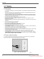
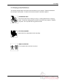
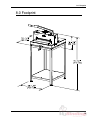
CHALLENGE
SPARTAN 150M
PAPER CUTTER
Instruction Manual
Provided By
http://www.MyBinding.com
http://www.MyBindingBlog.com
Serial Numbers 041001 & Up
OPERATOR’S
MANUAL
SPARTAN 150 M
DIGITAL/LEVER
PAPER CUTTER
Sold and Serviced by
The Challenge Machinery Company
6125 Norton Center Drive
Norton Shores, MI. 49441
www.challengemachinery.com
F.150M-O
Apr 2007
1.0 Introduction
1.0 Introduction
THIS MANUAL is designed to help you get the most from your Challenge equipment. Keep this
manual in a safe, convenient place for quick reference by operators and service personnel.
SAFETY ALERT! This symbol means CAUTION: Personal safety
instructions! Pay special attention to the instructions in bold type. Personal injury may result if the
precautions are not read and followed.
READ THIS MANUAL BEFORE OPERATING! Follow precautions and instructions. If after reading
the manual, questions remain, please contact your Authorized Challenge Dealer.
Take a few minutes right now to RECORD YOUR MACHINE SERIAL NUMBER in the space
provided on the front cover of this manual. Also be sure to fill out the warranty card accompanying
your machine and return it DIRECTLY TO CHALLENGE.
If you bought a used machine, it is important to have the following information on record at Challenge.
Copy this page, fill in the information and send it care of The Challenge Service Department, 6125
Norton Center Drive, Norton Shores MI. 49441.
CHALLENGE MODEL Spartan 150 M
ATTN
SERIAL NUMBER
COMPANY
ADDRESS
CITY
PHONE
DEALER NAME & CITY
STATE/PROVINCE
DATE INSTALLED
ZIP
* WARRANTY INFORMATION *
It is very important that you read and understand the conditions outlined in the Warranty Information
Sheet attached to the outside of the shipping container of your machine.
The Warranty Information Sheet must be filled out completely and returned to THE CHALLENGE
MACHINERY COMPANY in order for the warranty to be issued for this machine.
Challenge® is a registered trademark of
The Challenge Machinery Company • 6125 Norton Center Drive • Norton Shores MI. 49441
Copyright© 2004 by The Challenge Machinery Company. All rights reserved. Printed in the U.S.A
2
1.0 Introduction
TABLE OF CONTENTS
1.0 Introduction .......................................................................................................................................2
2.0 Safety ................................................................................................................................................4
2.1 Precautions ...................................................................................................................................4
2.2 Power Lockout Procedure ............................................................................................................4
2.3 Warning Label Definitions.............................................................................................................5
3.0 Packing List.......................................................................................................................................7
4.0 Specifications ....................................................................................................................................8
5.0 Installation & Setup ...........................................................................................................................9
5.1 Inspecting Shipment .....................................................................................................................9
5.2 Uncrating ......................................................................................................................................9
5.3 Cleaning........................................................................................................................................9
5.4 Power Hook-Up ............................................................................................................................9
5.5 Mounting to Optional Stand ..........................................................................................................9
6.0 Operation ........................................................................................................................................10
6.1 Main Power .................................................................................................................................10
6.2 Backgauge Control .....................................................................................................................11
6.3 Jogging Aid .................................................................................................................................12
6.4 Line Light ....................................................................................................................................13
6.5 Making a Cut...............................................................................................................................13
6.6 Adjusting the Knife Depth ...........................................................................................................14
6.7 Operating Tips ............................................................................................................................14
7.0 Knife Installation/Changing .............................................................................................................15
7.1 Knife Removal ............................................................................................................................15
7.2 Knife Installation .........................................................................................................................16
7.3 Knife Care Tips ...........................................................................................................................17
7.3.1 Knife Blade Life ...................................................................................................................17
7.3.2 Cutting Stick ........................................................................................................................17
7.3.3 Bevel Angle .........................................................................................................................18
7.3.4 Helpful Suggestions ............................................................................................................18
7.3.5 Knife Care............................................................................................................................18
8.0 Footprint ..........................................................................................................................................19
9.0 Safety Systems Test .......................................................................................................................20
3
2.0 Safety
2.0 Safety
2.1 Precautions
•
•
•
•
•
•
•
•
•
•
•
•
•
•
•
•
This machine is designed for one-person operation. Never operate the machine with more than
one person.
Safe use of this machine is the responsibility of the operator. Use good judgment and common
sense when working with and around this machine.
Read and understand all instructions thoroughly before using the machine. If questions remain,
contact the dealer from which you purchased this machine. Failure to understand the operating
instructions may result in personal injury.
Only trained and authorized people should operate this machine.
DO NOT ALTER SAFETY GUARDS OR DEVICES. They are for your protection. Severe
personal injury may result.
Disconnect power before cleaning or performing maintenance. See Section 2.2 Power Lockout
Procedure.
Observe all caution labels on this machine.
Be sure the cutter is properly grounded.
Be sure there is sufficient power to operate the cutter properly.
Observe all caution plates mounted on this cutter.
Keep foreign objects off table and away from cutter blade.
BE EXTREMELY CAREFUL when handling and changing the cutter knife. Severe lacerations or
dismemberment could result from careless handling procedures.
Keep the floor around the cutter free of trim, debris, oil and grease.
When replacing hydraulic parts, loosen the connections slowly to release pressure. Never loosen
connections with the machine running.
If the cutter sounds or operates unusually, have it checked by a qualified service person.
CRUSH HAZARD, keep hand and fingers from under the clamp when clamping paper. Use
Jogging Aid to load paper, and use the backgauge to push paper out before unloading. DO NOT
REACH UNDER THE KNIFE AND CLAMP AREA!
2.2 Power Lockout Procedure
For maximum safety while making adjustments or repairs to your machine, be sure to disconnect
power to the machine. Disconnect the power plug from its socket.
Figure 1 - Main Power Disconnect
4
2.0 Safety
2.3 Warning Label Definitions
The following warning labels are found at various locations on your machine. Read and understand
the meaning of each symbol. If a label is lost from the machine, it should be replaced.
HAZARDOUS AREA
Disconnect power before cleaning, servicing, or making adjustments not requiring
power. Do not alter safety guards or devices; they are for your protection. Replace
all guards. Do not operate with any guards removed.
CUT/CRUSH HAZARD
Keep hands from underneath the knife and clamp.
SINGLE OPERATOR
Do not operate with more than one person.
5
2.0 Safety
!OJO!
This Este simbolo de alerta de seguridad significa ¡ OJO ! INSTRUCCIONES DE SEGURIDADPERSONAL. Lea las instrucciones porque se refieren a su
seguridad personal. Fall de obedecer las instrucciones que siguen podria resultar en lesiones
corporales.
•
•
•
•
•
•
•
•
•
•
•
•
•
•
•
•
•
•
•
•
Esta maquina, junto con sus mecanismos de seguridad, esta disenada para ser manejada por
UNA SOLA PERSONA a la vez. Jamas debe ser manejada por mas de una persona al mismo
tiempo.
La seguridad es la responsabilidad del operario que usa esta maquina.
LEA DETENIDAMENTE el manual de instrucciones y las PRECAUCIONES DE SEGURIDAD
antes de poner a funcionar la cortadora. Pidale a su supervisor una copia.
El manejo de la guillotina debe estar exclusivamente a cargo de personal entrenado y autorizado
para ello.
NO MODIFIQUE LOS MECANISMOS DE SEGURIDAD, estan ahi para su proteccion no deben
ni modificarse ni quitarse.
DESCONECTE LA CORRIENTE ELECTRICA antes de proceder a hacerle servicio de limpieza,
engrasar, o de hacer adjustes que no requieren corriente. Trabe el interruptor en la posicion
OFF (apagado); vea “Procedimiento para cortar la corriente electrica” al pie de esta pagina.
Eche llave a la guillotina y quite la llave cuando la maquina no esta en operacion; vea “Corriente
electrica”.
Asegurese de que la guillotina este debidamente a tierra. Vea “Conexion de la fuerza electrica”.
Verifique el voltaje y asegurese de que este sea suficiente para el debido funcionamiento de la
guillotina.
Preste atencion a todas las placas con advertencias instaladas en esta guillotina.
No permita que objetos estranos esten en la mesa o cerca de la cuchilla cortadora.
TENGA SUMO CUIDADO al tocar y cambiar la cuchilla. Heridas severas y hasta
desmembramiento pueden resultar del manejo sin cuidado o negligente.
El suelo alrededor de la guillotina debe mantenerse despejado y libre de recortes, desperdicios,
aceite y grasa.
Al haber la necesidad de reemplazar partes hidraulicas, afloje todas las conexiones poco a poco
para dejar escapar la presion. Jamas debe aflojarse conexiones mientras la maquina este
andando.
Si la guillotina empezara a sonar o trabajar diferentemente a lo acostumbrado, desconectela y
consulte la seccion “Troubleshooting” (Reparador) de este manual. Si no es posible corregir el
problema, llame a su servicio autorizado para que le examinen la maquina.
PELIGRO DE MACHUQUE - Mantenga manos y dedos fuera de la agarradera mientras sujeta el
papel. Use el calibrador trasero y su rueda de mano para empujar el papel cortado. NO PONGA
SUS MANOS BAJOLA CUCHILLA O AREA DE LA AGARRADERA.
NO OPERE SIN LAS GUARDAS PROTECTORAS!
¡ OJO ! PRECAUCION -
Como proceder para desconectar
la corriente electrica.
Para maxima seguridad durante ajustes y reparaciones de su maquina, verifique bien que el interruptor principal
de control de corriente al cual la maquina esta conectada, este desconectado. El interruptor deba ser puesto en
la posicion “OFF” (desconectado) y se debe poner un candado en la anilla. La llave del candado debe ser
guardada por la persona que estara efectuando los trabajos de servicio o de reparacion en la guillotina.
Desconecte la corriente electrica antes de proceder a hacer cualquier ajuste o reparacion o de efectuar el
engrase en cualquier maquina.
6
3.0 Packing List
3.0 Packing List
Part No.
Spartan 150 M
60011-2
60057
F.150M-O
60058
60061
61036
5064
W-189
W-190
Description
15” Digital/Lever Paper Cutter
Knife – Standard (installed in machine)
Cutting Stick
Operator Manual
Jogging Aid
Knife Lifter Assembly
Lever Handle
Cut Stick Puller
5/32” Hex ‘T’ Allen Wrench
1/8 Hex Wrench- Short Arm
Qty.
1
1
1
1
1
1
1
1
1
1
Optional Items
Part No.
60057
60011-2
60011-1
61070
Description
Extra Cutting Sticks
Knife – Standard
Knife – Long Lasting H.S.S.
Stand
Qty.
1
1
1
1
7
4.0 Specifications
4.0 Specifications
Description
Inch Units
Cutting Width
15-3/4”
Minimum Cut
1-15/16”
Clamp Opening
1-1/2”
Table Space
Front:
6-1/4”
Back:
15-1/4”
Dimensions
Overall Height
12-1/2”
Overall Height with Optional
45-1/4”
Stand
Table Height with Optional
36”
Stand
Overall Length
27-1/4”
Overall Width
28-1/8”
Approx. Net Weight
80 lbs
Approx. Shipping Weight
110 lbs
Approx. Weight of Optional
60 lbs
Stand
Electrical
120 Volts 60 HZ. 11 W, Service Size 15 Amps
Metric Units
40 cm
4.9 cm
3.8 cm
15.9 cm
38.7 cm
31.8 cm
115 cm
91.4 cm
69.2 cm
71.4 cm
36 kg
50 kg
27 kg
Sound Emission
N/A
Challenge reserves the right to make changes to any product or specification without notice and
without incurring responsibility to existing units.
8
5.0 Installation & Setup
5.0 Installation & Setup
5.1 Inspecting Shipment
This machine has been carefully packed to prevent damage during shipment. However, claims for
damage or loss are the responsibility of the recipient. Inspect all shipments as soon as they are
received. If there is any noticeable damage, note it on the freight bill. Visual and/or hidden damage
must be reported to the claims department of the carrier within 15 days. Contact your dealer if you
need any assistance. Check the contents of the box against the packing list on page 7. Make sure
there are no missing items.
5.2 Uncrating
The Spartan 150 weighs approximately 80 lbs (36 kg). DO NOT risk personal injury or damage by
attempting to move machinery with makeshift equipment or inadequate help. This machine is
shipped on a wooden skid and enclosed in a protective, wooden frame and corrugated carton.
Remove the carton by removing the nails or staples holding it to the wooden frame and lift it straight
up over the cutter. Remove the wooden uprights and cut the plastic straps. Carefully lift machine off
skid and set on to work surface or optional stand (see section 5.5 Mounting to Optional Stand).
Screw the lever handle onto the cutting lever.
5.3 Cleaning
After unpacking, wipe down all machine panels and surfaces with a clean cloth.
5.4 Power Hook-Up
SHOCK HAZARD! Possible shock could cause personal injury or death.
Connect A/C adapter to any standard 120 Volt outlet. Have a qualified electrician install one if your
location is not so equipped. The socket-outlet shall be installed near the machine’s location and be
easily accessible.
Figure 2 – A/C Adapter
5.5 Mounting to Optional Stand
Place the machine on the stand. No portion of the machine base should overhang the top shelf of the
o
stand. If it does, rotate the machine 90 and place it back on the stand. Line up two holes in the top
shelf of the stand with two holes on the underside of the machine base. Fasten the machine to the
stand using two 1/4 –20 screws provided with the stand. These screws are used to prevent the
machine from tipping over while cutting.
9
6.0 Operation
6.0 Operation
IMPORTANT: DO NOT ATTEMPT TO OPERATE THE CUTTER UNTIL
YOU HAVE THOROUGHLY READ AND UNDERSTAND ALL OF THE FOLLOWING
INSTRUCTIONS. CALL YOUR AUTHORIZED CHALLENGE DEALER IF YOU STILL HAVE ANY
QUESTIONS.
Cutting Lever Handle
Cutting Lever
Clamp Handle
Knife Latch
Lever
Backgauge
Position Display
Front
Shield
Backgauge
Hand Crank
Figure 3 – Machine Controls
6.1 Main Power
Power is enabled when the A/C adapter is plugged in and when the connector is plugged into the
socket at the back, left table (Figure 4). The display and line light are switched on at this time.
Figure 4 – Connect Power to the Machine
10
6.0 Operation
6.2 Backgauge Control
The backgauge is used to position paper to the desired location when cutting. The backgauge is
operated by the hand crank at the front of the machine. The backgauge position is shown by a
lighted LED display. When the machine is first powered up, the display shows four lines as follows,
indicating the display needs to be reset.
Figure 5 – Display at power up
To reset the display, bring the backgauge to the forward most position. If the backgauge is already at
the forward most position, move the backgauge back by a few turns, then bring it forward again. Now
the display should show the actual position of the backgauge (Figure 6). If the machine is left on all
of the time, this should be done at least once per day. The position of the decimal point indicates
whether the reading is in inches or millimeters. Two digits to the right of decimal indicates inches,
one digit to the right of decimal indicates millimeters. To switch from inches to mm and vice-versa,
press the inch/mm button located next to the display.
Figure 6 – Display with backgauge at 2.00 inches
11
6.0 Operation
6.3 Jogging Aid
Always remove the jogging aid from the table before making a cut.
A jogging aid is included as standard equipment with the Spartan 150. This tool allows the operator
to load and align paper without the need to place hands or arms under the knife or clamp.
To use, load the paper against the side and backgauge using the jogging aid (Figure 7 & Figure 8).
Remove the jogging aid from the table, close the shield, clamp the paper, and make the cut.
Figure 7
Figure 8
12
6.0 Operation
6.4 Line Light
The Spartan 150 comes standard with an LED line light. The line light switches on and stays on
whenever the power is on. To use, simply align paper under clamp, and use the red light line as an
indicator of where the cut will be made (Figure 9).
Figure 9 – Line Light
6.5 Making a Cut
Open the front shield and set the backgauge to the desired position. Place the paper square against
the backgauge and either side guide. Clamp down on the paper using the clamp hand-wheel located
on top of the machine. Close the front shield. Move the red-capped knife latch lever and pull the
cutting lever to the left. Once the cutting lever has moved slightly, the knife latch lever may be
released. Two hands may then be used to complete the cut. Firmly seat the knife into the plastic
cutting stick to assure all sheets are completely cut. If all sheets are not completely cut see 6.6
Adjusting the Knife Depth to adjust the cutting depth. Move the cutting lever to its original position
and raise the hood. The hood will not open unless cutting lever is at its right-most position.
Raise the clamp by turning the hand-wheel and remove the cut pieces of paper.
13
6.0 Operation
6.6 Adjusting the Knife Depth
The depth of cut can be adjusted using the knife depth adjusting screw located on the left side of the
machine. The same T-handled wrench used for changing the knife can be used to adjust the screw.
Turn the screw counter-clockwise to increase knife depth, and clockwise to decrease knife depth. It
is better to make several slight adjustments and perform test cuts in between, than to make large
adjustments and cut too deep. Try to avoid setting the knife too deep because this can cause
premature wear on knife and/or damage the cut stick.
Knife Adjusting
Screw
Figure 10 – Knife Depth Adjustment
6.7 Operating Tips
Carefully lay out each sheet before you start cutting. Find the best cut pattern to give you the most
pieces out of the sheet. If the sheet will be folded, be sure grain of the paper is running in the same
direction as the fold or you will get a rough edge on the fold.
If an accurate cut is necessary for close register work, you MUST have a sharp blade in the cutter. A
dull blade will pull or draw the paper and cause uneven cutting. Increased clamp pressure will not
eliminate draw caused by a dull knife.
The correct clamping pressure varies from paper to paper. The general rule is that you should have
enough pressure to hold the paper securely but not so much that it marks the surface of the paper
excessively. Excessive pressure causes pile distortion and inaccurate cuts.
Mark the gripper edge and the guide edge of printed paper and make sure the first cuts are with these
guide edges against the backgauge.
When cutting business cards or narrow strips of paper, place lifts of equal height on opposite sides of
the table to provide better clamping.
14
7.0 Knife Installation/Changing
7.0 Knife Installation/Changing
Changing knives can be very dangerous unless safety precautions are
observed and extreme care is taken when handling knives.
•
•
•
•
•
•
Make sure knife lifters are used properly, see instructions following.
Keep handling of unprotected knives to an absolute minimum.
Clear off cutter table before removing knife.
Have scabbard nearby and insert knife immediately.
Warn people of any unprotected knife.
Knife changing is a ONE PERSON OPERATION. Having more than one person trying to
change knives invites accidents.
Knife Lifter
Assembly
5/32”
T-Wrench
Knife
Scabbard
Figure 11 – Spartan 150 Knife Change Accessories
The knife changing equipment shown in Figure 11 is included with the machine. The following
instructions show how to remove and install a new or re-sharpened knife. Read these instructions AT
LEAST ONCE before attempting to actually change or install any blades.
7.1 Knife Removal
Knives are always very sharp! Be sure to keep the edge away from your
body and keep other people out of the area while handling the blade. Severe lacerations or
dismemberment could result from careless handling procedures.
1. Lower the clamp to the table and remove the clamp handle and cutting lever handle.
2. Remove the top cover.
15
7.0 Knife Installation/Changing
3. With the knife at its extreme up position, lift the hood.
4. Remove the two knife bolts that are mounted in open slots in the knife bar.
5. Install the knife lifter onto the knife holder. Screw the handles into the holes from which the
two, knife bolts were removed. Firmly tighten each handle.
6. Remove the remaining knife bolts.
7. Place an empty knife scabbard on a nearby flat surface.
8. Slowly loosen the handles until the knife can be freed from the knife bar. Move the knife to
the right or left and remove it from the machine at an angle.
9. Place the knife on the scabbard and remove the knife lifter. Carefully slide the knife to line up
holes in the knife with holes in the scabbard. Secure the knife to the scabbard using the
scabbard screws.
10. Send dull knives to a knife grinder – do not attempt to sharpen your own knives! Knives that
do not have a minimum height of 1-1/2” (3.8 cm) will not function properly and should be
carefully discarded. See the Knife Care Tips Section below for additional information.
7.2 Knife Installation
Knives are always very sharp! Be sure to keep the edge away from your
body and keep other people out of the area while handling the blade. Severe lacerations or
dismemberment could result from careless handling procedures.
1. If a knife is currently installed or the top cover is installed, see the previous section for
instructions on knife removal. The clamp should be lowered to the table. The clamp handle
and top cover should be removed from the machine.
2. Raise the hood. Pull out the cut stick and turn it to a new surface or replace with a new one.
3. Remove the retainer screws from the new blade and screw the knife lifters into the new
blade. Screw the lifters about half way into the knife.
4. Insert the knife assembly into position under the knife bar. Raise the knife into the knife bar
slot as high as it will go. Check all view holes to make sure knife is all the way up. Tighten
the lifters.
NOTE: If the blade will not go in, make sure the lifters are not screwed into the blade too far.
5. Insert and tighten (4) knife bolts into the knife.
6. Loosen the knife lifter handles and remove the knife lifter.
7. Insert and tighten the remaining (2) knife bolts.
8. Reinstall the top cover, clamp handle, and lever-arm handle.
9. Adjust depth of cut by placing sheets of paper across the entire width of the cutting area.
Clamp the paper and make a cut. Adjust the knife depth adjustment screw just until the
16
7.0 Knife Installation/Changing
entire width of paper is cut completely through. Do not allow the knife to cut too deep into the
cut stick. Cutting excessively deep into the stick will reduce its life.
10. Send dull knives to a knife grinder – do not attempt to sharpen your own knives! Knives that
do not have a minimum height of 1-1/2” (3.8 cm) will not function properly and should be
carefully discarded. See the Knife Care Tips Section below for additional information.
7.3 Knife Care Tips
! KNIFE SAFETY ! Knives are DANGEROUS!!! Knives are very sharp,
even after use. Keep the edge away from your body and keep the area clear of others when handling
knives. Never touch the cutting edge! To prevent personal injury and damage to the knife, always
keep knives in their holders with screws tightened. Even if you are aware of the dangers, others may
not be. Never attempt to hone, polish, or service the knife in any way. Failure to follow safety
procedures may result in severe lacerations or dismemberment.
7.3.1 Knife Blade Life
Knife blade life, or the time between sharpening, can be affected by many factors. One important
factor is the type of paper being cut. Abrasive paper, such as recycled paper, soft paper such as
newsprint and bound books can all significantly shorten knife blade life. In addition, if the knife depth
is set too deep, the knife will cut too deep into the cutting stick and can quickly dull the knife blade.
A knife can last between 2,000 and 5,000 cuts before it needs to be sharpened. Cutting soft paper
(such as newsprint paper) or paper with high post-consumer recycled content can cause the knife to
need sharpening after only 2,000 to 3,000 cuts. Cutting pure paper, such as bond paper with no
recycled content or hard paper can allow the knife to be used for as many as 5,000 cuts before it
needs to be sharpened. In all cases, the operator should continually check the quality of the cut to
determine when the knife blade needs to be sharpened. Some characteristics that indicate a blade
needs sharpening are:
•
The cut requires too much effort.
•
The sheets are not all cut to the same length (usually the top few sheets are longer than the
rest of the sheets - this is sometimes called “draw”).
•
Cut marks or scoring appears on the cut face of the paper.
•
The profile of the cut (side view) is not perpendicular to the table.
•
The cut does not appear straight when viewed from the top.
•
The knife makes a “rough” sound as it passes through paper.
•
Nicks are visible on the cutting edge of the knife.
7.3.2 Cutting Stick
A worn cutting stick can affect the cut quality of the bottom sheets. When this happens, the cut stick
can be rotated. Usually, the stick should be rotated one or two times between knife sharpening. Cut
sticks have a “wavy” shape to them and when rotated must be rotated a full 180° to keep a flat side
up. Each stick has 2 flat sides that can be used, after which it can be turned end to end, allowing the
2 flat sides to be used again, for a total of 4 positions per cut stick.
17
7.0 Knife Installation/Changing
7.3.3 Bevel Angle
Challenge recommends that the bevel angle for the Spartan 150 knives be 20°. Order a reO
sharpened knife to the following specification, “20 , DEAD SHARP, NO MICRO-BEVEL.” A microbevel on this knife will cause strenuous cutting. If an operator requires cutting with less physical
o
o
strain, knives may be re-sharpened to 18 . Note, however, that a knife sharpened at 18 has a
shorter lifetime and is more susceptible to damage.
7.3.4 Helpful Suggestions
•
It may be helpful to own a “set” of knives. A set consists of 3 knives: one in the machine,
one as back up, and one at the grinder.
•
If the machine seems to strain but the cut quality is still good, reduce the pile height. You
may also carefully apply glycerin to the bevel when cutting hard, coated paper. Tie a cloth to
the end of a stick; dip the stick in glycerin, and apply. Never apply by hand! In lieu of
glycerin, you may lightly rub white bar soap along the bevel. Lubrication will prolong the life
of your machine and reduce maintenance.
7.3.5 Knife Care
18
•
To prevent corrosion, new knives are coated with light oil. It should be REMOVED WITH
CARE.
•
While removing or installing a knife, be careful not to allow the edge to bump against the
machine. Nicks will result.
•
If a knife bolt is damaged, replace it.
•
Always keep knife bolts securely tightened.
•
Store knives in a dry environment to prevent corrosion.
•
Never attempt to service a knife in any way.
8.0 Footprint
8.0 Footprint
19
9.0 Safety Systems Test
9.0 Safety Systems Test
Machine manufacturer
CHALLENGE
Model
SPARTAN 150 M
Serial Number __________________
Frequency of test: THESE TESTS SHOULD BE PERFORMED WEEKLY.
Test #1: Move the cutting lever to its right-most position. Move the knife latch to the right and the
cutting lever slightly to the left. Attempt to lift the hood. The machine requires service if the hood lifts
more than approximately 1 inch. If the machine fails this test, do not use it until a qualified technician
has serviced it. The knife interlock requires servicing.
Test #2: Move the lever arm to the left and release it at various locations. The lever should not move
while it is not being held. If the lever moves after release, do not use it until a qualified technician has
serviced it. The knife bar gibs require adjustment.
20
9.0 Safety Systems Test
Please enter date and initials for both tests.
Date
______ ______ ______ ______ ______ ______ ______ ______ ______ ______ ______
Test 1 ______ ______ ______ ______ ______ ______ ______ ______ ______ ______ ______
Test 2 ______ ______ ______ ______ ______ ______ ______ ______ ______ ______ ______
Date
______ ______ ______ ______ ______ ______ ______ ______ ______ ______ ______
Test 1 ______ ______ ______ ______ ______ ______ ______ ______ ______ ______ ______
Test 2 ______ ______ ______ ______ ______ ______ ______ ______ ______ ______ ______
Date
______ ______ ______ ______ ______ ______ ______ ______ ______ ______ ______
Test 1 ______ ______ ______ ______ ______ ______ ______ ______ ______ ______ ______
Test 2 ______ ______ ______ ______ ______ ______ ______ ______ ______ ______ ______
Date
______ ______ ______ ______ ______ ______ ______ ______ ______ ______ ______
Test 1 ______ ______ ______ ______ ______ ______ ______ ______ ______ ______ ______
Test 2 ______ ______ ______ ______ ______ ______ ______ ______ ______ ______ ______
Date
______ ______ ______ ______ ______ ______ ______ ______ ______ ______ ______
Test 1 ______ ______ ______ ______ ______ ______ ______ ______ ______ ______ ______
Test 2 ______ ______ ______ ______ ______ ______ ______ ______ ______ ______ ______
Repairs
_________________________________________
_________________________________________
_________________________________________
_________________________________________
_________________________________________
_________________________________________
_________________________________________
_________________________________________
_________________________________________
_________________________________________
_________________________________________
_________________________________________
_________________________________________
Initials of
Repairer
________
________
________
________
________
________
________
________
________
________
________
________
________
Date
_____________
_____________
_____________
_____________
_____________
_____________
_____________
_____________
_____________
_____________
_____________
_____________
_____________
21