1
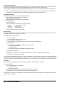
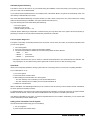
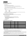
MODEL MS2000
VEHICLE SECURITY SYSTEM
Table of Contents
1. Before You Begin . . . . . . . . . . . . . . . . . . . . . . . . . . . . . . . . . . . . . . . . . . . . . . . . . . . . . . . . . .Page 1
2. Installation Tips . . . . . . . . . . . . . . . . . . . . . . . . . . . . . . . . . . . . . . . . . . . . . . . . . . . . . . . . . . .Page 1
3. Mounting Components . . . . . . . . . . . . . . . . . . . . . . . . . . . . . . . . . . . . . . . . . . . . . . . . . . . . . .Page 2
4. Wiring Description . . . . . . . . . . . . . . . . . . . . . . . . . . . . . . . . . . . . . . . . . . . . . . . . . . . . . . . . .Page 3
5. Wiring Diagram . . . . . . . . . . . . . . . . . . . . . . . . . . . . . . . . . . . . . . . . . . . . . . . . . . . . . . . . . . . .Page 4
6. Parking Light Jumper Settings . . . . . . . . . . . . . . . . . . . . . . . . . . . . . . . . . . . . . . . . . . . . . . .Page 4
7. Basic Operation . . . . . . . . . . . . . . . . . . . . . . . . . . . . . . . . . . . . . . . . . . . . . . .
Remote Transmitter Layout . . . . . . . . . . . . . . . . . . . . . . . . . . . . . . . .
Optional Driver Door Priority Feature . . . . . . . . . . . . . . . . . . . . . . . . .
Remote Arming . . . . . . . . . . . . . . . . . . . . . . . . . . . . . . . . . . . . . . . . .
Remote Sensor Bypass . . . . . . . . . . . . . . . . . . . . . . . . . . . . . . . . . . .
Remote Disarming . . . . . . . . . . . . . . . . . . . . . . . . . . . . . . . . . . . . . . .
Tamper Alert . . . . . . . . . . . . . . . . . . . . . . . . . . . . . . . . . . . . . . . . . . .
Silent Arming / Disarming . . . . . . . . . . . . . . . . . . . . . . . . . . . . . . . . .
Arming Mode Selection . . . . . . . . . . . . . . . . . . . . . . . . . . . . . . . . . . .
Passive Arming . . . . . . . . . . . . . . . . . . . . . . . . . . . . . . . . . . . . . . . . .
Panic Mode . . . . . . . . . . . . . . . . . . . . . . . . . . . . . . . . . . . . . . . . . . . .
Automatic System Rearming . . . . . . . . . . . . . . . . . . . . . . . . . . . . . . .
Full Time System Diagnostics . . . . . . . . . . . . . . . . . . . . . . . . . . . . . .
Valet Mode . . . . . . . . . . . . . . . . . . . . . . . . . . . . . . . . . . . . . . . . . . . .
Adding a New Transmitter . . . . . . . . . . . . . . . . . . . . . . . . . . . . . . . . .
Deleting Transmitters . . . . . . . . . . . . . . . . . . . . . . . . . . . . . . . . . . . . .
.
.
.
.
.
.
.
.
.
.
.
.
.
.
.
.
.
.
.
.
.
.
.
.
.
.
.
.
.
.
.
.
.
.
.
.
.
.
.
.
.
.
.
.
.
.
.
.
.
.
.
.
.
.
.
.
.
.
.
.
.
.
.
.
.
.
.
.
.
.
.
.
.
.
.
.
.
.
.
.
.
.
.
.
.
.
.
.
.
.
.
.
.
.
.
.
.
.
.
.
.
.
.
.
.
.
.
.
.
.
.
.
.
.
.
.
.
.
.
.
.
.
.
.
.
.
.
.
.
.
.
.
.
.
.
.
.
.
.
.
.
.
.
.
.
.
.
.
.
.
.
.
.
.
.
.
.
.
.
.
.
.
.
.
.
.
.
.
.
.
.
.
.
.
.
.
.Page
.Page
.Page
.Page
.Page
.Page
.Page
.Page
.Page
.Page
.Page
.Page
.Page
.Page
.Page
.Page
5
5
5
5
6
6
6
7
7
7
7
8
8
8
8
9
8. Programming
Entering System Programming . . . . . . . . . . . . . . . . . . . . . . . . . . . . . . . . . . . . . . . . .Page 10
System Initialization and Default Reset . . . . . . . . . . . . . . . . . . . . . . . . . . . . . . . . . .Page 10
Programmable System Parameters . . . . . . . . . . . . . . . . . . . . . . . . . . . . . . . . . . . . .Page 10
9. Shock Sensor
Sensor Test Mode . . . . . . . . . . . . . . . . . . . . . . . . . . . . . . . . . . . . . . . . . . . . . . . . . .Page 12
10. Diagrams
Starter Defeat . . . . . . . . . . . . . . . . . . . . . . . . . . . . . . . . . . .
Door Lock Diagrams . . . . . . . . . . . . . . . . . . . . . . . . . . . . . .
Driver Door Priority Wiring Diagrams . . . . . . . . . . . . . . . . . .
Dome Light . . . . . . . . . . . . . . . . . . . . . . . . . . . . . . . . . . . . .
Tech Tips . . . . . . . . . . . . . . . . . . . . . . . . . . . . . . . . . . . . . . .
.
.
.
.
.
.
.
.
.
.
.
.
.
.
.
.
.
.
.
.
.
.
.
.
.
.
.
.
.
.
.
.
.
.
.
.
.
.
.
.
.
.
.
.
.
.
.
.
.
.
.
.
.
.
.
.
.
.
.
.
.
.
.
.
.
.
.
.
.
.
.
.
.
.
.
.
.
.
.
.
.
.
.
.
.
.Page 12
.Page 13
.Page 14
.Page 15
.Page 15
11. Reference Chart . . . . . . . . . . . . . . . . . . . . . . . . . . . . . . . . . . . . . . . . . . . . . . . . . . . . . . . . .Page 16
Before You Begin
1.
Be sure to read the manual thoroughly before beginning the installation to ensure a proper understanding of the MS2000
and its functions.
2.
Verify system contents:
q Main Unit
q Two 3-Button Remote Transmitters
q Siren
q Electronic Shock Sensor
q Harnesses
• 14-Pin Main harness
• 2-Pin Status LED harness
• 2-Pin Override Switch harness
• 3-Pin Door Lock harness
• 4-Pin Shock Sensor harness
3.
Discuss the location of the status LED and the Emergency Override Switch with the vehicle’s owner.
4.
Discuss the optional features of the MS2000 and the features that must be programmed during installation, with the
vehicle’s owner.
5.
Check all of the vehicle’s operating systems before and after the installation.
Installation Tips
1.
Use a Volt / Ohm meter to test all wires. Do not use a test light.
2.
Good power and ground connections are essential for proper operation. Ground the alarm as close to the alarm main unit
as possible.
3.
Route all wires from the engine compartment to the interior of the vehicle through a grommet and use electrical tape and/or
split loom tubing for protection.
4.
When adding optional accessories such as door locks, window modules, etc., be sure to fuse each additional accessory
power lead separately from the main power source. This will insure that the security system power is retained in the event
that an accessory malfunctions.
5.
Avoid extending the system’s wires, the supplied wiring harnesses provide sufficient length to connect to the required
vehicle circuits. If a wire must be extended, be sure to use the appropriate gauge wire in order to avoid a drop in current.
Always use wire that is at least the same gauge as the wire you are extending.
6.
Never bypass the fuses included in the MS2000 wiring harness. They are necessary safety items designed to protect both
the system and the vehicle.
7.
Be sure to perform a full function test of all of the systems components to verify proper operation. Also, be sure to check
all of the vehicle’s operating systems before and after the installation.
8.
For maximum security, disguise all system wires with black electrical tape and/or split loom tubing to prevent a thief from
being able to identify the system wiring.
Page 1 - MS2000 Installation Manual
Mounting Components
Main Unit
The main unit should be mounted in the interior of the vehicle. Do not mount the main unit in the engine compartment. For
maximum security, avoid mounting the main unit where it will be easily accessible to a thief.
If you are mounting the unit under the dash board, be sure to mount the unit as high as possible and in a location where
it will not interfere with the operation of the pedals.
Be sure to extend the antenna as high as possible so that optimum range can be achieved.
Before securing the unit, be sure that you have made all of the necessary switch and jumper selections and perform a
thorough function test of the system.
The case of the MS2000 is designed to be mounted using screws, or secured using wire ties through the wire tie mounting
tabs located on the unit.
Siren
Mount the siren away from sources of heat and face the opening downward to prevent water from collecting inside the
housing. Be sure that the wires are not easily accessible from underneath the vehicle.
For maximum security, it is best to disguise all under hood system wires with factory style split loom tubing so that they
cannot be easily identified by a thief.
Shock Sensor
The dual stage, electronic shock sensor, included with the system, is designed to be mounted in the interior of the vehicle
using a tie wrap or double sided tape. Be sure to avoid mounting the sensor to sources of strong electrical interference
such as cellular phone transceivers or the vehicle’s engine computer.
Suggested mounting locations are an air conditioning duct, or a dashboard or center console support brace.
Override Switch
Mount the Override Switch in a location near the driver where it is easily accessible but not plainly visible. Plug the blue
override switch connector into the blue 2-pin socket on the main unit.
Be sure that the switch cannot accidentally be pressed or damaged by movement of passengers or contents within the
vehicle.
LED Status Indicator
Mount the status LED so that it is visible from both sides of the vehicle. Plug the red LED connector into red 2-pin socket
on the Main Unit.
MS2000 Installation Manual- Page 2
Wiring Description
14-Pin Main Harness
Pin 1 - Red: Main Power (+12v) input [15A fuse]
Connect to constant +12v. A clean source of power is essential. This connection can be made at either the battery or at
the constant power supply wire to the ignition switch.
If this wire needs to be lengthened, use the appropriate wire gauge to avoid a drop in current and be sure to install a fuse
near the connection. Do not remove or bypass the fuse holder included on the wire harness.
Pin 2 - Brown: Siren (+12v) output.
Connect to the Red siren wire. Connect the Black siren wire to chassis ground.
Pin 3 - White: Parking Light (+/-) output.
Connect to the parking light circuit. For vehicles that have independent left and right parking light circuits, the parking light
wires must be connected using diodes to keep the circuits separate.
Pin 4 - * Blank *
Pin 5 - Blue/White: Passenger/Priority Unlock (-) output.
Provides a negative output (-) while the alarm is disarmed to unlock the vehicle’s passenger door. Connect to an optional
relay. (See Door Lock Diagrams - Page 13)
Pin 6 - Brown/White: Horn Honk (-) output.
Connect to a relay to honk the vehicle horn.
Pin 7 - Orange: Optional Circuit Defeat (-) output.
Provides a negative output to disable the vehicle’s ignition or fuel pump circuits. Connect to an optional relay as shown.
Pin 8 - Blue: Hood/Trunk Trigger (-) input.
Connect to a negative output from the hood and trunk pin switches.
Pin 9 - Black/White: Dome Light (-) output.
Illuminated Entry/Exit output. Provides a negative (-) output to turn on the vehicle’s dome light when the system is
disarmed. Normally, this wire can be connected to the door switch circuit. (See Dome Light Diagrams - Page 15)
Pin 10 - Yellow/White: Auxiliary (-) output.
Provides a negative (-) momentary output.
Pin 11 - Yellow: Ignition input (+12v) input.
Connect to a source that maintains +12v when the ignition key is in both the "on" and "start" positions.
Pin 12 - Black: Ground.
Connect to a solid chassis ground. Be sure to use a ring connector of proper size. Scrape away the paint at the grounding
point.
Pin 13 - Violet: Door Trigger (+12v) input
Connect to positive door switch circuit. This circuit, commonly found in Ford vehicles, will show (+12v) when the door is
open.
Pin 14 - Green: Door Trigger (-) input
Connect to negative door switch circuit. This circuit will show (-) when the door is open.
3-Pin Door Lock Harness (See Door Lock Diagrams - Page 14)
Pin 1 - Green: (-) output
Pin 2 - Red: Not used
Pin 3 - Blue: (-) output
On-Board Starter Defeat Wiring
(See Starter Defeat Diagram - Page 12)
Pin 1 - Brown: Starter Defeat Input
Cut the vehicle’s starter wire at the ignition column and connect the key side to the brown wire.
Pin 2 - Brown: Starter Defeat Output
Cut the vehicle’s starter wire at the ignition column and connect the starter side to the brown wire.
Page 3 - MS2000 Installation Manual
Wiring Diagram
Parking Light Jumper Settings
The Parking Light Polarity Jumper selects the polarity (+/-) for the output of the on-board Parking Light relay.
Pin 1 + Pin 2 = negative
Pin 2 + Pin 3 = positive (default)
Negative
Positive
MS2000 Installation Manual- Page 4
Basic Operation
LED
Remote Transmitter Layout:
Button 1
Button 2
Button 3
Each system comes with 2 Remote Transmitters, pre-programmed to operate in the Standard Mode and will Arm and Disarm
the system with chirp confirmation.
Button 1 Arms the system. This Button also locks the doors when the system is in Valet Mode.
Button 2 Disarms the system. This Button also unlocks the doors when the system is in Valet Mode.
Button 3 Activates the the systems trunk release feature. Silently arms/disarms the system.
Optional Driver Door Priority Feature*
This configuration adds the security of unlocking only the driver’s door when the system is Disarmed. Pressing the Disarm
button again will unlock all remaining doors.
Button 1 Arms the system. This Button also locks the doors when the system is in Valet Mode.
Button 2 Disarms the system and unlocks the driver’s door. This Button also unlocks the doors when the system is in Valet
Mode.
If the system is Armed, pressing Button 2 will Disarm the system and unlock the driver’s door only.
If the system is Disarmed, pressing Button 2 will unlock all remaining doors.
If the system is in Valet and the doors are locked, pressing Button 2 will unlock the driver’s door. Pressing Button 2 again
will unlock all remaining doors.
*Extra parts and/or labor may be required to properly utilize this feature.
Remote Arming
When Armed, the system monitors and protects 4 independent areas or zones, including the doors, hood/trunk, shock sensor
and optional sensor.
To Arm the System:
1. Turn off the ignition.
2. Press Button 1.
•
•
•
•
The siren/horn will chirp once.*
The doors will lock.
The parking lights will flash once.
The LED will turn on red, indicating the doors, hood and trunk inputs are activated.
* The siren chirp(s) during Arming will alert you the condition of the system and vehicle when the system is armed.
1 chirp
=
1 + 4 chirps =
normal arming
door, hood, or trunk open
During Arming, if the system detects a bad sensor or an open zone, the system will ignore that input, but keep all other
areas protected.
3. After 10 seconds:
• The LED will begin blinking, indicating that the sensor inputs are activated.
While the system is Armed, the system will trigger if:
• The doors are opened.
Page 5 - MS2000 Installation Manual
• The shock sensor detects an impact to the vehicle.
• The hood or trunk is opened.
• A connected optional sensor is disturbed.
When triggered, the siren will sound, and the parking lights will flash and the horn will honk (if connected). If the system
is triggered by the doors, hood, or trunk, the system will sound alarm for 40 seconds. If triggered by a sensor, the system
will sound alarm for 20 seconds.
If the same input triggers the system 3 times during a single arming cycle, the system will bypass that input keeping the
other zones protected until the next time the system is armed.
If the shock sensor detects a light impact to the car or a connected optional sensor triggers the system’s Warn Away input,
the siren will sound 5 chirps to warn away the potential intruder.
Remote Sensor Bypass
In case of extreme weather conditions such as high winds, the sensors can be temporarily bypassed from the Remote
Transmitter while the system is armed to prevent the system from false alarming.
To Bypass the sensors:
1. After arming the system, press Button 1 again on the Remote Transmitter within 5 seconds.
• The siren will chirp 5 times, indicating the sensors have been bypassed.
2. The sensors will remain bypassed until the next time the system is armed.
Remote Disarming
To Disarm the System:
Press Button 2.
• The siren/horn will chirp twice.*
• The doors will unlock.
• The parking lights will flash twice.**
• The LED will turn off.
* The siren chirps and light flashes during disarming will alert you if the system had been triggered while armed.
2 chirps / 2 flashes = normal disarming
3 chirps / 3 flashes = Tamper Alert - system was triggered
** If the Passenger Unlock Feature is installed, pressing Button 2 will unlock only the driver’s door. Pressing the unlock
Button 2 again unlocks all doors.
Tamper Alert
On Disarming, if the system responds with three chirps, indicating the system was triggered, the LED will flash for 60 seconds
to indicate the zone that triggered the system.
LED Flashes (60 seconds):
1 flash
= door
2 flashes = shock sensor
3 flashes = trunk
4 flashes = optional sensor
example: flash-flash-pause-flash-flash-pause = shock sensor
Note: Turning on the ignition will cancel Tamper Alert zone indications.
MS2000 Installation Manual - Page 6
Silent Arming / Disarming
Each Remote Transmitter can be individually set to always Arm and Disarm the system with or without chirp confirmation at
the time they are programmed into the system (See Adding a New Transmitter into the System Page 9).
To temporarily cancel the Arming and Disarming confirmation chirps, you can Arm or Disarm the system by pressing Button 3.
Note: The confirmation chirps will only be cancelled if the system status is normal. The chirp indications for Tamper Alert
and the open zone warning will not be cancelled when the system is Armed or Disarmed silently.
Arming Mode Selection
Your system can be set in one of the following Arming Modes:
• Passive (automatic) Arming with chirp confirmation
• Active Arming (by Remote Only)
• Passive (automatic) Arming without chirp confirmation
To set the Arming Mode:
1. Turn the ignition on.
2. Within 4 seconds, press Button 3 to change the setting.
one chirp
=
two chirps =
three chirps =
Passive Arming with chirp
Active Arming
Passive without chirp
3. Turn the ignition off to save your selection.
Passive Arming
When the Arming Mode has been set for Passive Arming, the system arms itself automatically, each time the ignition is turned
off and all of the doors, hood and trunk are closed.
To start the Passive Arming Process:
1. Turn off the ignition.*
• The status LED will begin to flash quickly.
2. Open the door and exit the vehicle.
• Once all doors are closed and the dome light is turned off, the LED will turn off.
3. After 20 seconds,
•
•
•
•
The siren will chirp (if Passive Arming with chirp is selected).
The parking lights will flash.
The doors will lock.**
The status LED will flash red, indicating the system is armed.
4. The system is now armed.
* The ignition must have been on for at least 10 seconds before the Passive Arming sequence will begin.
** If the Passive Locking feature is selected.
To temporarily disable Passive Arming, you can turn the ignition key on then off within 10 seconds. The status LED will stop
flashing, and the system will not passively arm until the next time the key is on for more than 10 seconds. This feature is useful
for turning off passive arming when refueling or washing the car or if you want to sit in your car and do not want the system to arm.
Panic Mode
Allows you to instantly trigger the alarm in an emergency situation using the Remote Transmitter.
To enter Panic Mode:
1. Press and hold Button 1 for 3 seconds.
• The siren will sound.
• The doors will unlock.
2. Press Button 1 again to stop panic and place system into the Armed state.
3. Press Button 2 to stop panic and place system into the Disarmed state.
If Panic Mode is not stopped by the Remote, it will automatically time out after 40 seconds, and the system will return to its
prior Armed/Disarmed state.
Page 7 - MS2000 Installation Manual
Automatic System Rearming
This feature, which can be turned on by your installer during the installation, insures the security of the system by protecting
your car in case of an accidental disarm.
If your system becomes disarmed due to an accidental press of the Disarm Button, the system will automatically rearm if no
other activity is detected within one minute.
One minute after Remote Disarming, the system will alert you with a series of chirps, then arm. (If the Passive Door Locking
feature is selected during the installation, the system will also relock the doors.)
Any of the following will cancel Automatic System Rearming:
• Turn on the ignition.
• Open the Trunk or Hood.
• Activate Auxiliary Function 1 or 2.
Automatic System Rearming is independent of Passive Arming and only takes place if the system was Armed (actively or
passively) for at least 10 seconds and then Disarmed by the Remote Transmitter.
Full Time System Diagnostics
The system continuously monitors all protected zones, even when it is not armed, and warns you if it detects a problem when
you turn off the ignition.
1. Turn off the ignition.
2. If the siren chirps twice, the system has detected a problem.*
3. The status LED will flash to indicate the zone where the problem has been detected.
1 flash
= door
3 flashes = hood / trunk
4 flashes = optional sensor
* The system must see the zone open or active for at least 20 seconds before the zone is determined to be defective. This
way, opening the car door before turning off the ignition will not cause the siren to emit the warning chirps.
Valet Mode
Allows you to temporarily disable the security system when the car is being service or turned over to a parking attendant.
To turn Valet Mode on or off:
1. Turn on the ignition.
2. Press and hold the override switch.
3. While holding the override switch, turn off the ignition.
• The siren will chirp once to indicate you have turned Valet Mode on.
• The siren will chirp twice to indicate you have turned Valet Mode off.
4. Release the override switch.
While in Valet Mode, the LED will light solid and you can continue to lock and unlock your doors with the Remote Transmitters,
as well as operate the Auxiliary Functions.
For added protection, when the doors are locked using the Remote Transmitter, the siren will chirp twice, the system’s Starter
Disable circuit will activate, and the LED will emit double flashes until the system is unlocked by the Remote.
If the Remote Transmitter is lost, stolen, or becomes inoperable while the car is locked in Valet Mode, you can exit the Valet
mode to deactivate the Starter Disable circuit.
Adding a New Transmitter into the System
Have all desired transmitters ready (up to 4 transmitters)
1. Turn on the ignition.
2. Press and hold the Override switch.
MS2000 Installation Manual - Page 8
• The status LED will turn on red.
• The siren will chirp 5 times.
3. Within 5 seconds follow the steps below for each transmitter:
Continue holding the Override switch and Press Transmitter Button 1 for remote arming with chirp confirmation.
--- or --Release the Override switch and Press Transmitter Button 1 for remote arming without chirp confirmation.
• The status LED will flash once quickly to confirm that the new Remote Transmitter has been added.
4. Turn off the ignition.
• The siren will chirp 3 times to confirm that the new Remote Transmitters have been added.
Deleting Transmitters (Adding a Remote Transmitter and Erasing All Other Transmitters From the System)
Code all memory locations to delete any lost transmitters. Example: if two transmitters are used, after coding the first
transmitter, code the second transmitter three times to fill up the remaining memory locations.
Page 9 - MS2000 Installation Manual
Programming
Entering System Programming
To enter System Programming:
1. Turn on ignition.
2. Within 5 seconds, press the valet switch 5 times.
• The siren will emit a buzzing sound, indicating that you have entered Programming.
3. Press the valet switch the number times equal to the System Parameter you want to change.
• The siren will chirp each time the valet switch is pressed.
4. Within 5 seconds, press the transmitter button corresponding to the desired operating mode for that System
Parameter.
• The siren will chirp to indicate the setting.
1 chirp
2 chirps
3 chirps
=
=
=
Button 1
Button 2
Button 3
5. When you are finished, turn the ignition key off to save the changes. You can turn the key off at any time during
programming and the changes that were made will be saved.
System Initialization and Default Reset
Following this procedure will set all System Programming Parameters to factory default settings.
1. Enter System Programming.
2. Press Transmitter Button 3.
• The siren will chirp 6 times indicating that the reset signal was received.
• All System Programming parameters are now set to factory default settings.
• The Arming Mode is set to Remote Arming only.
• The Valet Mode is off.
• The Disarm Code is 1.
3. Turn ignition off.
Programmable System Parameters
Feature
1. Ignition Controlled Door Locking
2. Ignition Controlled Door Unlocking
3. Door Unlock Pulse
4. Door Lock Pulse Width
5. Passive Locking
6. Door Entry Delay with Passive Arming
7. Ignore Dome Light Delay
8. Auto Rearm
9. Horn Honk / Arming Output
10. Trunk Disarm Feature
11. Siren / Horn Chirps
Button 1 (default)
On
On
Single
1 second
Off
Off
Off
Off
Continuous
Off
Siren only
Button 2
Off
Off
Double
4 seconds
On
On
Ignore
On
Flashing
On
Horn chirps
Button 3
1.
Ignition Controlled Door Locking. Selects whether or not the system automatically locks the doors when the ignition is
turned on. When selected, the Ignition Controlled Door Locking feature will automatically lock the doors 10 seconds after the
ignition key is turned on.
To prevent the keys from being locked inside the vehicle when Ignition Controlled Door Locking is on:
• The system will not lock the doors if any door is open when the ignition is turned on.
• The system will not lock the doors if any door is opened during the 10 second countdown.
2. Ignition Controlled Door Unlocking. Selects whether or not the system automatically unlocks the doors when the ignition
is turned off. When selected, the Ignition Controlled Door Unlocking feature will automatically unlock the doors when the
ignition key is turned off.
3. Door Unlock Pulse - Single/Double. Selects between a single pulse or a double pulse door unlock output.
On many late model Nissan vehicles, as well as some European makes, the factory door locking system requires two pulses
MS2000 Installation Manual - Page 10
on the proper wire to unlock the vehicle’s doors. By programming the system for double pulse door unlocking, these systems
can be interfaced directly without the use of relays or any additional circuitry.
4. Door Lock Pulse Width. Selects between a 1-second and a 4-second output for door locking and unlocking. Set to 4
seconds when interfacing into vehicles equipped with vacuum door locking systems.
5. Passive Locking. Selects whether or not the system will automatically lock the doors with Auto Rearm and Passive Arming.
6. Door Entry Delay with Passive Arming. When selected, the door input trigger will be delayed for 15 seconds, allowing
access to the emergency override switch. Only delays when the system is armed passively.
7. Ignore Dome Light Delay. For use with vehicles equipped with a timed dome light circuit that stays on after the door has
been closed. When programmed ON, the open zone indication function will ignore the door zone.
8. Auto Rearm. When selected, the system will automatically rearm if no other activity is detected within one minute of Remote
Disarming.
One minute after Remote Disarming, the system will alert you with a 10 second series of chirps, then arm. (If the Passive
Door Locking feature is selected during the installation, the system will also relock the doors.)
Any of the following will cancel Automatic System Rearming:
• Turn on the ignition.
• Activate the Auxiliary Function.
• Open the Trunk or Hood.
Automatic System Rearming is independent of Passive Arming and only takes place if the system was Armed (actively or
passively) for at least 15 seconds and then Disarmed by the Remote Transmitter.
9. Horn Honk / Arming Output. Selects between pulsed or constant output for the Brown/White wire.
10. Trunk Disarm Feature. When selected, this feature will automatically disarm the alarm when the auxiliary 1 function (trunk)
is activated.
11. Siren / Horn Chirps. When set for Horn Chirps, the horn will honk when arming and disarming allowing the siren to NOT
be installed.
Page 11 -MS2000 Installation Manual
Shock sensor
Sensor Test Mode
This mode will allow you to actively test the shock sensor
and make adjustments without the alarm being armed. Be
sure that the sensor is securely mounted to the vehicle
before entering the Sensor Test mode.
To enter Sensor Test mode:
1. Turn the ignition on.
2. Within 4 seconds, press Button 1.
• The siren will chirp 4 times, indicating that the sensor is ready to be tested.
3. Test the sensitivity. The siren will respond with a short chirp each time an impact is detected.
• The green led on the sensor will turn on when a light (warn away) impact is detected.
• The red led on the sensor will turn on when a heavy (trigger) impact is detected.
4. To make adjustments:
• Turn the adjustment screw on the sensor clockwise to increase the sensitivity.
• Turn the adjustment screw on the sensor counter clockwise to decrease the sensitivity.
5. When you are satisfied with the sensitivity, turn off the ignition.
Starter Defeat / Optional Circuit Defeat
The on-board starter defeat relay is designed for normally closed operation only. Connect the brown wires as shown.
Starter Defeat
The optional circuit defeat output is programmable for normally closed or normally open operation. Connect the circuit
to be interrupted as shown, then program the orange wire to the desired operating mode.
Optional Circuit Defeat
MS2000 Installation Manual - Page 12
Door Lock Wiring Diagrams
Negative Pulse Door Lock System
Positive Pulse Door Lock System
Vacuum Pump Systems
Reverse Polarity Door Lock System
Actuator Diagram
Page 13 - MS2000 Installation Manual
Driver Door Priority Wiring Diagrams
Positive Pulse Door Lock System
with Driver Door Priority
Negative Pulse Door Lock System
with Driver Door Priority
Reverse Polarity Door Lock System
with Driver Door Priority
MS2000 Installation Manual - Page 14
Dome Light
Negative Dome Light
Positive Dome Light
Tech Tips
Remote Audio System Activation (Latched Operating Mode)
This enables the user to listen to the vehicle’s audio or video system for extended periods without need of the vehicle’s ignition key.
When the Aux 2 function is pressed, the radio will turn on until either the Aux 2 function is pressed again, or the user arms the alarm. In
this manner, the user cannot forget to turn off the radio and drain the vehicle’s battery.
Normal operation of the audio system using the ignition key is unaffected.
Remote Headlight Activation (Timed Operating Mode)
This enables the user to conveniently light the path to their door for nighttime safety.
When the Aux 2 function is pressed, the vehicle’s headlights will turn on for 30 seconds, then turn off.
Remote Audio System Activation
Page 15 - MS2000 Installation Manual
Remote Headlight Activation
Reference Chart
You can use this chart to quickly identify and interpret the system’s chirp indications and LED flashes.
Output
1 chirp
1 + 4 chirps
When
arming
arming
Status
normal arming
door, hood, or trunk is open
No chirps
LED double flashes
arming
Valet Mode
Valet Mode is on
Starter Defeat Activated
2 chirps
disarming
normal disarming
3 chirps
disarming
Tamper Alert - system was triggered
after Tamper Alert
after Tamper Alert
after Tamper Alert
after Tamper Alert
door
shock sensor
hood or trunk
optional sensor
5 chirps
while Armed
Warn Away
Continuous chirps
while Armed & Door Open
System Triggered
(Passive Arming Entry Delay Warning)
4 chirps
1 chirp
with ignition key on
in Sensor Test mode
Sensor Test mode on
impact detected
Multiple chirps
(for 10 seconds)
1 minute after disarming
Automatic Rearming
LED flashing quickly
ignition key off
Passive Arming sequence started
Two chirps
1 LED flash
2 LED flashes
3 LED flashes
ignition key off
after Full Time Sys. Diag.
after Full Time Sys. Diag.
after Full Time Sys. Diag.
Full Time System Diagnostics
door
shock sensor
hood or trunk
1 LED flash
2 LED flashes
3 LED flashes
4 LED flashes
MS2000 Installation Manual - Page 16