1
PIXMA MP830
SERVICE
MANUAL
Canon
Copyright 2006, Canon U.S.A. This technical publication is the proprietary and confidential information of Canon U.S.A. which
shall be retained for reference purposes by Authorized Service Facilities of Canon U.S.A. Its unauthorized use is prohibited.
Trademarks
Product and brand names appearing in this manual are registered trademarks or trademarks of the respective holders.
Copyright
All rights reserved. No parts of this manual may be reproduced in any form or by any means or translated into another language without the written
permission of Canon Inc., except in the case of internal business use.
Copyright © 2006 by Canon Inc.
CANON INC.
Inkjet Device Quality Assurance Div. 2
451, Tsukagoshi 3-chome, Saiwai-ku, Kawasaki-shi, Kanagawa 212-8530, Japan
I. MANUAL OUTLINE
This manual consists of the following three parts to provide information necessary to service the PIXMA MP830:
Part 1: Maintenance
Information on maintenance and troubleshooting of the PIXMA MP830
Part 2: Technical Reference
New technology and technical information such as FAQ's (Frequently Asked Questions) of the PIXMA MP830
Part 3: Appendix
Block diagrams and pin layouts of the PIXMA MP830
Reference:
This manual does not provide sufficient information for disassembly and reassembly procedures. Refer to the graphics in the separate Parts Catalog.
II. TABLE OF CONTENTS
Part 1: MAINTENANCE
1. MAINTENANCE
1-1. Adjustment, Periodic Maintenance, Periodic Replacement Parts, and Replacement Consumables by Service Engineer
1-2. Customer Maintenance
1-3. Product Life
1-4. Special Tools
1-5. Serial Number Location
2. LIST OF ERROR DISPLAY / INDICATION
2-1. Operator Call Errors
2-2. Service Call Errors
2-3. Fax Errors
2-4. Other Error Messages
2-5. Warnings
2-6. Troubleshooting by Symptom
3. REPAIR
3-1. Notes on Service Part Replacement (and Disassembling / Reassembling)
3-2. Special Notes on Repair Servicing
(1) Power supply unit removal / reassembly
(2) Cassette, front door (paper output tray), and door damper removal
(3) Emblem removal
(4) Side cover (right and left) removal
(5) Front cover (right and left) removal
(6) DF front cover removal
(7) DF rear cover removal
(8) Stop arm removal
(9) DF grip cover and DF right cover removal
(10) Document feed unit removal
(11) Separation tab, document feed roller, and separation roller cleaning
(12) DF cable cover removal
(13) ADF hinge removal
(14) Operation panel (right and left) removal
(15) LCD upper cover removal
(16) Operation panel unit removal
(17) LCD unit removal
(18) Logic board ass'y wiring
(19) Scanner stop arm removal
(20) Scanner stopper removal
(21) Cable holder sheet position
(22) Scanner unit removal
(23) Main case unit removal
(24) Base case and printer unit wiring
(25) Logic board ass'y removal
(26) Printer unit removal
3-3. Adjustment / Settings
(1) Paper feed motor adjustment
(2) Grease application
(3) Waste ink counter setting
(4) White sponge sheet attachment
(5) User mode
(6) Service mode
Service mode operation
Destination settings
LF correction
Waste ink amount setting
Button and LCD test
3-4. Verification Items
(1) Service test print
(2) EEPROM information print
(3) Fax report
4. MACHINE TRANSPORTATION
Part 2: TECHNICAL REFERENCE
1. NEW TECHNOLOGIES
2. CLEANING MODE AND AMOUNT OF INK PURGED
3. PRINT MODE
3-1. Normal Color Printing via Computer
3-2. Normal Grayscale Printing via Computer
3-3. Borderless Printing via Computer
3-4. Duplex Printing via Computer
3-5. Camera Direct Printing
3-6. Card Direct Printing
3-7. Copying
4. FAQ (Problems Specific to the MP830 and Corrective Actions)
Part 3: APPENDIX
1. BLOCK DIAGRAM
2. CONNECTOR LOCATION AND PIN LAYOUT
2-1. Logic Board Ass'y
2-2. NCU Board
2-3. Relay Board
2-4. Card Slot Board
2-5. Operation Panel Board
2-6. Carriage Board (Print Head Connector)
3. PIXMA MP830 SPECIFICATIONS
Part 1
MAINTENANCE
1. MAINTENANCE
1-1. Adjustment, Periodic Maintenance, Periodic Replacement Parts, and Replacement Consumables by
Service Engineer
(1) Adjustment
Adjustment
Timing
Purpose
Tool
Approx.
time
EEPROM initialization At logic board replacement
To initialize settings.
None.
Destination settings
(EEPROM settings)
At logic board replacement
To set the destination.
None.
1 min.
Perform in the service
mode.
Waste ink counter
resetting
(EEPROM settings)
- At logic board replacement
To reset the waste ink counter.
- At waste ink absorber replacement
Waste ink amount
setting
- At logic board replacement
To set the waste ink amount to the waste ink None.
1 min.
counter.
Perform in the service
mode.
Paper feed motor
position adjustment
At paper feed motor replacement
To adjust the belt tension. (Position the
None.
paper feed motor so that the belt is stretched
tight.)
CD / DVD detection
sensor light volume
correction*1
- At logic board replacement
- At carriage unit replacement
To correct the light volume for the CD /
DVD detection sensor.
None.
2 min.
Perform in the service
mode.
Grease application
- At carriage unit replacement
- At PR shaft ass'y replacement
- At CL base or CL gear
replacement
- To maintain sliding properties of the
carriage shaft and the lift cam shaft.
- To protect the machine's sliding portions
(gears and Open button).
1 min.
FLOIL KG-107A
MOLYKOTE PG-641
Ink system function
check
- At logic board replacement
- At platen unit replacement
- At carriage unit replacement
To maintain detection functionality for
presence of the ink tanks and each ink tank
position.
1 min.
None.
Perform in the service
mode.
Line feed correction
- At logic board replacement
- At feed roller ass'y replacement
To correct the line feed tolerant accuracy.
None.
3 min.
LCD language settings
At logic board replacement
To set the language to be displayed on the
LCD.
None.
Perform in the user
mode.
1 min.
Document pressure
sheet position
adjustment
- At document pressure sheet
replacement
- At document feed base
replacement
To adjust the pressure sheet to fit in place to None.
the four corners of the platen glass when the
cover is closed.
(EEPROM settings)
1 min.
None.
1 min.
Perform in the service
mode.
5 min.
2 min.
Note: DO NOT loosen the red screws at both ends of the carriage shaft, securing the print head position, as they are not re-adjustable.
The red screws securing the paper feed motor may be loosened only at replacement of the paper feed motor unit.
*1: Only for CD / DVD printing supported regions.
(2) Periodic maintenance
No periodic maintenance is necessary.
(3) Periodic replacement parts
There are no parts in this machine that require periodic replacement by a service engineer.
(4) Replacement consumables
There are no consumables that require replacement by a service engineer.
1-2. Customer Maintenance
Adjustment
Timing
Print head alignment At print head replacement.
Purpose
To ensure accurate dot placement.
1-1
Tool
- Machine buttons
- Computer (automatic
settings via the MP
driver)
Approx.
time
3 min.
Print head cleaning
When print quality is not satisfying.
To improve nozzle conditions.
- Machine buttons
1 min.
- Computer (settings via the
MP driver)
Print head deep
cleaning
When print quality is not satisfying, and
not improved by print head cleaning.
To improve nozzle conditions.
- Machine buttons
2 min.
- Computer (settings via the
MP driver)
Ink tank
replacement
When an ink tank becomes empty. ("No
ink error" displayed on the monitor, or
short flashing of an ink tank LED)
To replace the empty ink tank.
None.
2 min.
Paper feed roller
cleaning
When paper does not feed properly.
To clean the paper feed rollers.
Machine buttons
2 min.
CD / DVD print
position
adjustment*1
At CD / DVD printing, when necessary.
To correct CD / DVD print position.
Computer (application
software)
5 min.
Bottom plate
cleaning
When the back side of the paper is
smeared.
To clean the platen ribs.
- Machine buttons
1 min.
- Computer (settings via the
MP driver)
Scanning area
cleaning
When the following are dirty:
To clean the applicable items.
Soft, dry, and clean lintfree cloth.
1 min.
1 min.
- Platen glass
- Document pressure sheet
- ADF glass
- White sheet in the back of the ADF
ADF cleaning
When inside of the ADF cover is dirty.
To clean the inside of the ADF cover
Soft, dry, and clean lintfree cloth.
ASF sub- roller
cleaning
When the paper fed from the ASF is
smeared due to ink mist attached to the
ASF sub-rollers.
To clean the ASF sub-rollers.
- Plain paper
1 min.
- Machine buttons (paper
feed roller cleaning)
[See Part 2, 4. FAQ, How
to make and set the ASF
sub-roller cleaning sheet,
for details]
*1: Only for CD / DVD printing supported regions.
1-3. Product Life
(1) Machine
Specified print volume (I) or the years of use (II), whichever comes first.
(I) Print volume: 19,000 pages
Fax
1,500 character pattern
230 pages
Black 1,500 character pattern
10,260 pages
Color A4, 7.5% duty per color pattern
7,450 pages
A4, photo, borderless printing
150 pages
4 x 6, photo, borderless printing
610 pages
Postcard, photo, borderless printing
300 pages
(II) Years of use: 5 years of use
(2) Print head
Same as the machine life.
(3) Ink tank (target value)
Pattern
Ink tank used
Print yield
Black text
PGI-5BK
Approx. 880 pages
Color chart
PGI-5BK
Approx. 1,250 pages
CLI-8C
Approx. 710 pages
CLI-8M
Approx. 500 pages
CLI-8Y
Approx. 480 pages
1-2
Photo chart
CLI-8BK
Approx. 1,100 pages
CLI-8C
Approx. 280 pages
CLI-8M
Approx. 250 pages
CLI-8Y
Approx. 390 pages
Black text: When printing the Canon standard pattern (1,500 characters per page) on A4 size plain paper, with the default settings in the
Windows XP driver, using Word 2003.
Color chart: When printing the ISO/JIS-SCID N5 pattern on A4 size plain paper in bordered printing, with the default settings in the Windows
XP driver, using Photoshop 7.0.
Photo chart: When printing the Canon standard pattern on 4" x 6" Photo Paper Plus Glossy in borderless printing, with the default settings in
the Windows XP driver, using Windows XP Photo Printing Wizard.
The print yield in the table above is an average value measured in continuous printing, using the ink tank immediately after it is unsealed, until
the ink is out. Ink yield may vary depending on texts and photos printed, application software, print mode, and type of paper used.
When the machine is turned on and while printing, each ink may be used for protecting the print head and maintaining print quality.
1-4. Special Tools
Name
Tool No.
Application
Remarks
FLOIL KG-107A
QY9-0057-000
To be applied to the sliding portions of the
carriage shaft, lift cam shaft, and machine's
sliding portions (gears).
In common with the
S520.
MOLYKOTE PG-641
CK-0562-000
To be applied to the Open button sliding
portion.
In common with the
i950.
1-5. Serial Number Location
On the carriage flexible cable holder (visible on the right of the carriage after the machine is turned on, the scanning unit is opened, and the
carriage moves to center).
To the table of contents
To the top
<Part 1: 1. MAINTENANCE>
1-3
2. LIST OF ERROR DISPLAY / INDICATION
Errors and warnings are displayed by the following ways:
1) Operator call errors are indicated by the Alarm LED lit in orange, and the error and its solution are displayed on the LCD in text and by icon.
2) Warnings during printing from a computer are displayed on the printer driver Status Monitor.
3) Error codes are printed in the "operator call/service call error record" area in EEPROM information print.
Buttons valid when an operator call error occurs:
1) ON/OFF button: To turn the machine off and on again.
2) OK button: To clear and recover from an error. In some operator call errors, the error will automatically be cleared when the cause of the error
is eliminated, and pressing the OK button may not be necessary.
3) Stop/Reset button: To cancel the job at error occurrence, and to clear the error.
2-1. Operator Call Errors (by Alarm LED Lit in Orange)
Error
Error code
Message on the LCD
Solution
No paper (ASF).
[1000]
Auto sheet feeder.
There is no paper. Load paper and press [OK].
Set the paper in the ASF, and press the OK
button.
No CD / DVD tray*1.
[1001]
There is no CD-R tray. Attach the tray and press
[OK].
Set the CD / DVD tray, and press the OK
button.
No paper in the front paper
feed cassette.
[1003]
Cassette.
Set the paper in the cassette, and press the OK
button.
No CD or DVD*1.
[1002]
Printable disc is not set. Correctly place a disc in the Set a CD or DVD in the CD / DVD tray
(which is ejected at error occurrence), and
CD-R tray and press [OK].
inset the CD / DVD tray in the proper
position. Then, press the OK button.
Paper jam.
[1300]
The paper is jammed. Clear the paper and press
[OK].
Remove the jammed paper, and press the OK
button.
There is no paper. Load paper and press [OK].
Paper jam in the rear guide. [1303]
Paper jam in the under
guide.
[1304]
No ink.
[1600]
Ink has run out. Replace the ink tank and close the
cover. (U041)
Replace the empty ink tank(s), and close the
cover.
Pressing the OK button will clear the error
without ink tank replacement, however, ink
may run out during printing.
Ink tank not installed.
[1660]
The following ink tank cannot be recognized.
(Applicable ink tank icon) (U043)
Install the applicable ink tank(s) properly, and
confirm that the LED's of all the ink tanks
light red.
The print head is not
installed, or it is not
properly installed.
[1401]
Print head is not installed. Install the print head.
(U051)
Install the print head properly.
Print head temperature
sensor error
[1403]
The type of print head is incorrect. Install the correct Re-set the print head. If the error is not
cleared, the print head may be defective.
print head. Replace the print head.
Faulty EEPROM data of the [1405]
print head
Inner cover open before
start of printing on paper
(print continuable).*2
[1841]
Inner cover is open. Close the inner cover and press
[OK].
Inner cover open during
printing on paper (print
NOT continuable).*2
[1846]
Close the inner cover, and press the OK
button to clear the error. The paper being
printed at error occurrence will be ejected
without printing the remaining data for the
ejected paper, then printing will resume from
the next page.
Inner cover open before
start of printing on paper
(print continuable).*1
[1851]
Close the inner cover, and press the OK
button.
Inner cover open during
printing on paper (print
[1856]
Close the inner cover, and press the OK
button to clear the error. The paper being
1-4
Close the inner cover, and press the OK
button.
NOT continuable).*1
printed at error occurrence will be ejected
without printing the remaining data for the
ejected paper, then printing will resume from
the next page.
Inner cover closed before
start of CD / DVD printing
(print continuable).*1
[1850]
Open the inner cover, place the CD-R tray and press Open the inner cover which functions as the
CD / DVD tray feeder, set the CD / DVD tray
[OK].
in the feeder, and press the OK button.
Inner cover closed during
CD / DVD printing (print
NOT continuable).*1
[1855]
Multiple ink tanks of the
same color installed.
[1681]
More than one ink tank of the following color is
installed. (U075)
Replace the wrong ink tank(s) with the
correct one(s).
Ink tank in a wrong
position.
[1680]
Some ink tanks are not installed in place. (U072)
Install the ink tank(s) in the correct position.
Warning: The waste ink
absorber becomes almost
full.
[1700]
The waste ink absorber is almost full. Press [OK] to
continue but early replacement recommended. <See
manual>
Press the OK button.
The service call error, indicating the waste
ink absorber is full, is likely to occur soon.
The connected digital
camera or digital video
camera does not support
Camera Direct Printing.
[2001]
Incompatible device detected. Remove the device.
Remove the cable between the camera and
the machine.
Automatic duplex printing
cannot be performed.
[1310]
This paper is not compatible with duplex printing.
Remove the paper and press [OK].
Press the OK button to eject the paper being
used at error occurrence. Printing will resume
from on the front side of the next page. Data
which was to be printed on the back side of
paper at error occurrence is skipped (not
printed).
Failed in automatic print
head alignment.
[2500]
Auto head align has failed. Press [OK] and repeat
operation. <See manual>
Press the OK button.
- If paper is being fed at error occurrence, the
error is indicated after the paper is ejected.
- If the error occurs, the print head alignment
values are not changed.
- After exit from the error by the OK button,
the automatic print head alignment will not
be re-done.
The error will occur when the print head
alignment pattern is not printed due to no ink
or non-ejection of ink.
The remaining ink amount
unknown.
[1683]
(Applicable ink tank icon)
The remaining level of the following ink cannot be
correctly detected.
An ink tank which has once been empty is
installed. Replace the applicable ink tank with
a new one.
Printing with a once-empty or refilled ink
tank can damage the print head.
Open the inner cover, and press the OK
button to clear the error. The CD or DVD
being printed at error occurrence will be
ejected without printing the remaining data
for the ejected CD or DVD, then the next
print job will be done.
If printing is continued without replacing the
refilled ink tank, press the Stop/Reset button
for 5 sec. or longer to record the use of a
refilled ink tank.
Note:
After the above operation, the function to
detect the remaining ink amount is disabled.
(Applicable ink tank icon)
A non-supported ink tank is installed (the ink
The following ink tank cannot be recognized. (U140) tank LED is turned off). Install the supported
ink tanks.
Ink tank not recognized.
[1684]
Ink tank not recognized.
[1410 to 1419] (Applicable ink tank icon)
An error occurred in an ink tank (the ink tank
[1682]
The following ink tank cannot be recognized. (U150) LED is turned off). Replace the ink tank(s).
Scanning unit (printer
cover) open.
[1200]
Scanner lock switch locked. [5020]
Cover is open. Close the cover.
Close the scanning unit (printer cover).
Release the scanner lock switch and turn the power
off and back on.
Turn the machine off, unlock the scanner lock
switch, then turn the machine on again.
*1: Only for models supporting CD / DVD printing
*2: Only for models not supporting CD / DVD printing
1-5
2-2. Service Call Errors (by Cyclic Blinking in Orange (Alarm LED) and Green (COPY button), or Alarm LED Lit
in Orange)
Service call errors are indicated by the number of cycles the Alarm LED and COPY button blink, and the corresponding error code is displayed
on the LCD.
Cycles of blinking in
orange (Alarm LED)
and green (COPY
button)
Error
Error
code
Conditions
[5100] An error occurred in the carriage encoder signal.
Solution
(Replacement of listed parts, which are
likely to be faulty)
2 times
Carriage error
3 times
Line feed error [6000] An error occurred in the LF encoder signal.
- Timing sensor unit
- Timing slit disk film
- Feed roller
- Platen unit
- Logic board
- Paper feed motor
4 times
Purge cam
sensor error
[5C00] An error occurred in the purge unit.
- Purge unit
- Logic board
5 times
ASF (cam)
sensor error
[5700] This error takes place when feeding paper from the
ASF after an error occurred in the ASF cam sensor.
- Sheet feed unit
6 times
Internal
temperature
error
[5400] The internal temperature is not proper.
- Logic board
- Carriage unit
7 times
Waste ink
absorber full
[5B00] The waste ink absorber is full.
- Ink absorber kit
8 times
Print head
[5200] The print head temperature exceeded the specified
temperature rise
value.
error
- Print head
- Logic board
9 times
EEPROM error [6800] A problem occurred in writing to the EEPROM.
- Logic board
11 times
Carriage lift
mechanism
error
[5110] The carriage did not move up or down properly.
- PR lift shaft
- Sheet feed unit
- Logic board
- Carriage lift sensor unit
12 times
AP position
error
[6A00] An error occurred in the AP motor during purging
operation.
- Sheet feed unit
- Logic board
- Purge unit
13 times
Paper feed
position error
[6B00] An error occurred in the paper feed motor.
- Sheet feed unit
- Logic board
14 times
Paper feed cam [6B10] An error occurred in the paper feed cam sensor during - Sheet feed unit
sensor error
paper feeding from the front paper feed cassette.
- Logic board
This error is also indicated when the waste ink counter
is 60% or more, and a paper jam occurs in the under
guide.
15 times
USB Host
VBUS
overcurrent
[9000] The USB Host VBUS is overloaded.
- Logic board
16 times
Valve sensor
error
[6C00] An error occurred in the valve sensor during cleaning.
- Logic board
- Purge unit
17 times
Motor driver
error
[6D00] The AD conversion value indicating the motor driver
temperature is not proper.
- Logic board
19 times
Ink tank
[6502] None of the ink tank position is detected.
position sensor
error
- Platen unit
- Logic board
20 times
Other hardware [6500] The PCI bus error is detected by the ASIC.
error
- Logic board
22 times
Scanner error
[5010] The scanner unit cannot detect the home position, or
the scanner unit warming-up is not done properly at
power-on.
On the LCD, "Scanner is not operating correctly." is
displayed.
- Scanner unit
Continuous alternate
ROM error
[6100] The check sum value is incorrect in the ROM check at - Logic board
1-6
- Carriage unit
- Timing slit film
- Logic board
- Carriage motor
blinking
hard-power-on.
Alarm LED lit
RAM error
[6300] The RAM error occurred in the RAM check at hardpower-on.
- Logic board
Note: Before replacement of the logic board ass'y, check the waste ink amount (by service test print or EEPROM information print). If the
waste ink amount is 7% or more, also replace the ink absorber kit (QY5-0153) when replacing the logic board ass'y. [See Section 3-3.
Adjustment / Settings, (6) Service mode, for details.]
2-3. Fax Errors
For errors other than those listed below, please refer to the "G3 / G4 Facsimile Error Code List (Rev. 2)."
(1) User error codes
Error code
TX / RX
Meaning
#001
TX
Document jam
#003
TX / RX
Document is too long, or page time-over
#005
TX / RX
Initial identification (T0 / T1) time-over
#009
RX
Recording paper jam, or no recording paper
#012
TX
No recording paper at the receiving machine
#017
TX
Redial time-over, but no DT detected
#018
TX
Auto dialing transmission error, or redial time-over
#022
TX
Call failed (no dial registration)
#037
RX
Memory overflow at reception of an image
#085
TX
No color fax function supported in the receiving machine
#099
TX / RX
Transmission terminated mid-way by pressing the Stop/Reset button
#995
TX / RX
During TX (sending): Memory transmission reservation cancelled
During RX (receiving): Image data received in the memory cleared
(2) Service error codes
Error code
TX / RX
Meaning
##100
TX
Re-transmission of the procedure signal has been attempted the specified number of times, but failed.
##101
TX / RX
Sender's modem speed does not match the receiving machine.
##102
TX
Fallback is not available.
##103
RX
EOL has not been detected for 5 seconds (or 15 seconds in CBT).
##104
TX
RTN or PIN has been received.
##106
RX
The procedure signal has been expected for 6 seconds, but not received.
##107
RX
Fallback is not available at the sending machine.
##109
TX
After DCS transmission, a signal other than DIS, DTC, FTT, CFR, or CRP has been received, and re-transmission of the
procedure signal has been attempted the specified number of times but failed.
##111
TX / RX
Memory error
##114
RX
RTN has been received.
##200
RX
A carrier has not been detected for 5 seconds during image reception.
##201
TX / RX
DCN has been received in a method other than the binary procedure.
##204
TX
DTC has been received even when there is no sending data.
##220
TX / RX
System error (main program hang-up)
##224
TX / RX
An error has occurred in the procedure signal in G3 transmission.
##226
TX / RX
The stack pointer has shifted from the RAM area.
##229
RX
The recording area has been locked for 1 minute.
##232
TX
The encoder control unit has malfunctioned.
##237
RX
The decoder control unit has malfunctioned.
##238
RX
The print control unit has malfunctioned.
##261
TX / RX
A system error has occurred between the modem and the system control board.
1-7
##280
TX
Re-transmission of the procedure signal has been attempted the specified number of times, but failed.
##281
TX
Re-transmission of the procedure signal has been attempted the specified number of times, but failed.
##282
TX
Re-transmission of the procedure signal has been attempted the specified number of times, but failed.
##283
TX
Re-transmission of the procedure signal has been attempted the specified number of times, but failed.
##284
TX
After TCF transmission, DCN has been received.
##285
TX
After EOP transmission, DCN has been received.
##286
TX
After EOM transmission, DCN has been received.
##287
TX
After MPS transmission, DCN has been received.
##288
TX
After EOP transmission, a signal other than PIN, PIP, MCF, RTP, RTN has been received.
##289
TX
After EOM transmission, a signal other than PIN, PIP, MCF, RTP, RTN has been received.
##290
TX
After MPS transmission, a signal other than PIN, PIP, MCF, RTP, RTN has been received.
##670
TX
In V.8 late start, the DIS V.8 ability from the receiving machine was detected, and CI was sent in response; however, the
procedure failed, causing T1 time-over.
##671
RX
In V.8 call reception, the procedure fails to proceed to phase 2 after CM detection, causing T1 time-over.
##672
TX
In V.34 transmission, the procedure fails to proceed from phase 2 to phase 3 or later, causing T1 time-over
##673
RX
In V.34 reception, the procedure fails to proceed from phase 2 to phase 3 or later, causing T1 time-over
##674
TX
In V.34 transmission, the procedure fails to proceed from phase 3 or 4 to the control channel or later, causing T1 timeover
##675
RX
In V.34 reception, the procedure fails to proceed from phase 3 or 4 to the control channel or further, causing T1 time-over
##750
TX
After transmitting PPS-NULL in ECM transmission, no significant signal has been received, and re-transmission of the
procedure signal has been attempted the number of specified times but failed.
##752
TX
After transmitting PPS-NULL in ECM transmission, DCN has been received.
##753
TX
After transmitting PPS-NULL in ECM transmission, re-transmission of the procedure signal has been attempted the
number of specified times but failed, or T5 time-over (60 sec.) has occurred.
##754
TX
After transmitting PPS-NULL in ECM transmission, re-transmission of the procedure signal has been attempted the
number of specified times but failed.
##755
TX
After transmitting PPS-MPS in ECM transmission, no significant signal has been received, and re-transmission of the
procedure signal has been attempted the number of specified times but failed.
##757
TX
After transmitting PPS-MPS in ECM transmission, DCN has been received.
##758
TX
After transmitting PPS-MPS in ECM transmission, re-transmission of the procedure signal has been attempted the
number of specified times but failed, or T5 time-over (60 sec.) has occurred.
##759
TX
After transmitting PPS-MPS in ECM transmission, re-transmission of the procedure signal has been attempted the
number of specified times but failed.
##760
TX
After transmitting PPS-EOM in ECM transmission, no significant signal has been received, and re-transmission of the
procedure signal has been attempted the number of specified times but failed.
##762
TX
After transmitting PPS-EOM in ECM transmission, DCN has been received.
##763
TX
After transmitting PPS-EOM in ECM transmission, re-transmission of the procedure signal has been attempted the
number of specified times but failed, or T5 time-over (60 sec.) has occurred.
##764
TX
After transmitting PPS-EOM in ECM transmission, re-transmission of the procedure signal has been attempted the
number of specified times but failed.
##765
TX
After transmitting PPS-EOP in ECM transmission, no significant signal has been received, and re-transmission of the
procedure signal has been attempted the number of specified times but failed.
##767
TX
After transmitting PPS-EOP in ECM transmission, DCN has been received.
##768
TX
After transmitting PPS-EOP in ECM transmission, re-transmission of the procedure signal has been attempted the number
of specified times but failed, or T5 time-over (60 sec.) has occurred.
##769
TX
After transmitting PPS-EOP in ECM transmission, re-transmission of the procedure signal has been attempted the number
of specified times but failed.
##770
TX
After transmitting EOR-NULL in ECM transmission, no significant signal has been received, and re-transmission of the
procedure signal has been attempted the number of specified times but failed.
##772
TX
After transmitting EOR-NULL in ECM transmission, DCN has been received.
##773
TX
After transmitting EOR-NULL in ECM transmission, re-transmission of the procedure signal has been attempted the
number of specified times but failed, or T5 time-over (60 sec.) has occurred.
##774
TX
After transmitting EOR-NULL in ECM transmission, ERR has been received.
##775
TX
After transmitting EOR-MPS in ECM transmission, no significant signal has been received, and re-transmission of the
procedure signal has been attempted the number of specified times but failed.
##777
TX
After transmitting EOR-MPS in ECM transmission, DCN has been received.
##778
TX
After transmitting EOR-MPS in ECM transmission, re-transmission of the procedure signal has been attempted the
1-8
number of specified times but failed, or T5 time-over (60 sec.) has occurred.
##779
TX
After transmitting EOR-MPS in ECM transmission, ERR has been received.
##780
TX
After transmitting EOR-EOM in ECM transmission, no significant signal has been received, and re-transmission of the
procedure signal has been attempted the number of specified times but failed.
##782
TX
After transmitting EOR-EOM in ECM transmission, DCN has been received.
##783
TX
After transmitting EOR-EOM in ECM transmission, re-transmission of the procedure signal has been attempted the
number of specified times but failed, or T5 time-over (60 sec.) has occurred.
##784
TX
After transmitting EOR-EOM in ECM transmission, ERR has been received.
##785
TX
After transmitting EOR-EOP in ECM transmission, no significant signal has been received, and re-transmission of the
procedure signal has been attempted the number of specified times but failed.
##787
TX
After transmitting EOR-EOP in ECM transmission, DCN has been received.
##788
TX
After transmitting EOR-EOP in ECM transmission, re-transmission of the procedure signal has been attempted the
number of specified times but failed, or T5 time-over (60 sec.) has occurred.
##789
TX
After transmitting EOR-EOP in ECM transmission, ERR has been received.
##790
RX
After receiving EOR-EOP in ECM reception, ERR has been transmitted.
##791
TX / RX
During the ECM mode procedure, a signal other than a significant one has been received.
##792
RX
In ECM reception, PPS-NULL between partial pages has not been detected.
##793
RX
During high-speed signal reception in ECM, no effective frame has been detected, and a time-over has occurred.
2-4. Other Error Messages
Message on the LCD
Cause
Solution
The selected paper cannot be fed from
cassette. Change the paper source.
The paper type being used is not supported for
paper feeding from the cassette.
Change the paper source to the ASF.
Cannot specify the followings together.
Change one of the settings.
Settings made conflict each other.
The error message is displayed for a while, then
the LCD automatically returns to the display
before the error occurrence.
Device memory is full. Cannot continue
process. Reduce the number of photos to
print.
The memory is not sufficient to do the print job.
Reduce the amount of data to be printed, or print
from a computer.
Failed to scan. Either document cannot be
scanned or is not placed on the platen
glass.
The machine failed in scanning the document for
Fit-to-page copy, or photos or films were not
recognized in pre-scanning.
Press the OK button to clear the error. The LCD
automatically returns to the display before the
error occurrence.
Press <>.
(<>: Color button icon)
The Black button was pressed, but it is invalid.
A temporary error. Press the Color button to
continue the operation.
Press <>.
(<>: Black button icon)
The Color button was pressed, but it is invalid.
A temporary error. Press the Black button to
continue the operation.
There are no photos in memory card.
Supported image files are not in the memory card. The error message is displayed for a while, then
disappears.
The value exceeds the number of copies
you can print.
During selecting images or specifying the number After the error message is displayed for a while,
of copies, the total print quantity exceeds the
the last operation before the error is cancelled, and
prescribed value of 999.
the total print quantity returns to the value before
the error.
Memory card is not set. Insert the card
after checking the direction.
No memory card is inserted in the slot.
Set a memory card.
DPOF information is not saved in the
memory card.
DPOF print was selected in the menu, but no
DPOF files are contained in the memory card.
The error message is displayed for a while, then
the LCD automatically returns to the display
before the error occurrence.
The number of copies to print is not set.
Input the number of copies.
Multi-photo print was attempted without
specifying the print quantity (with the print
quantity left "0" (zero)).
The error message is displayed for a while, then
disappears. Specify the print quantity.
This layout is available only for A4 or
8.5"x11"(LTR).
In Layout print, "Mixed 1, 2, or 3" which is
available only with A4 or LTR size paper is
selected, but the paper size is not set to A4 or
LTR.
The error message is displayed for a while, then
the LCD automatically returns to the display
before the error occurrence.
Settings cannot be changed when printing
stickers.
With Sticker print selected, the Settings button
was pressed.
The error message is displayed for a while, then
the LCD automatically returns to the display
before the error occurrence.
1-9
Change the setting after removing the card. With a memory card inserted in the slot, change of The error message is displayed for a while, then
the Read/Write attribute was attempted.
the LCD automatically returns to the display
before the error occurrence.
The card is currently write-enabled. Set to
read-only mode before performing
operation.
With the memory card set to the Read/write mode, The error message is displayed for a while, then
Card Direct printing operation was attempted from the LCD automatically returns to the display
the menu.
before the error occurrence.
The paper size is not correct. Check the
page size you have set.
Non-supported size of paper for PictBridge
Camera Direct printing is selected.
Cancel printing on the digital camera.
Failed to scan Photo Index Sheet. Check
The machine failed in scanning the Photo Index
the orientation, position and marking. <See Sheet.
manual>
Press the OK button to clear the error. The LCD
automatically returns to the display before the
error occurrence.
Photo scan error. Photo size is too large.
Leave at least 10mm between photos.
Press the OK button to clear the error. The LCD
automatically returns to the display before the
error occurrence.
In cropping multiple photos at the same time,
since the space between the photos were not
sufficient, the photos were considered as a single
JPEG file, and the file became too large.
2-5. Warnings
Warning
Low ink
Message on the LCD
Solution
The following ink is low. Continue?
(Icon of each ink tank)
Yes No
In Camera Direct Printing, only "Yes" can be selected.
- Select Yes, and press the OK button.
=> Printing starts, and it is indicated on the LCD.
- Select No, and press the OK button.
=> Printing is cancelled, and the LCD returns to the
display immediately before printing was
attempted.
Print head temperature rise
If the print head temperature does not fall, the error code When the print head temperature falls, the error is
"5200" is displayed, indicating the print head temperature automatically cleared.
rise error.
Note:
If the print head temperature exceeds the specified limit
when the scanning unit (printer cover) is opened, the
carriage does not move to the ink tank replacement
position.
Protection of excess rise of
the print head temperature
If the print head temperature does not fall, the error code If the print head temperature exceeds the specified limit,
"5200" is displayed, indicating the print head temperature an intermission is inserted during printing.
rise error.
Restrictions on paper
The current paper cannot be set. Change the size and type. Re-select the supported paper type and size.
Recommendation of the
print head alignment (only
on arrival of the machine)
Head alignment required. Load paper and press [OK].
Yes No
- Select Yes, and press the OK button.
=> Automatic print head alignment is performed.
- Select No, and press the OK button.
=> The procedures on arrival of the machine are
finished.
USB cable not connected
Connect USB cable and turn on the PC.
Connect the USB cable.
Cancellation of trimming
Reset trimming effect?
Yes No
With a trimmed image present, when printing on a DVD
or CD is attempted, the message is displayed.
- Select Yes, and press the OK button.
=> The trimming is cancelled, and printing on a DVD
or CD can be performed.
- Select No, and press the OK button.
=> The LCD returns to the display immediately before
the message was displayed.
Cancellation of image select Reset the selected photo information?
information
Yes No
When one or more images are selected in Multi-photo
print or Layout print, and if a user tries to display the
menu or sub-menu, the message is displayed.
- Select Yes, and press the OK button.
=> The image selection is cancelled, and the menu or
sub-menu is displayed.
- Select No, and press the OK button.
=> The LCD returns to the display immediately before
the message was displayed.
1-10
2-6. Troubleshooting by Symptom
Symptom
Faulty operation
Solution
The power does not turn on.
The power turns off immediately after poweron.
- Confirm the connection of
- the power cord, and
- between the logic board and the power supply unit.
- Replace the
- power supply unit, or
- logic board.
A strange noise occurs.
- Remove foreign material.
- Attach a removed part if any.
- Check the operation of the moving parts (such as purge unit,
carriage unit, and paper feeding mechanism)
- Replace a faulty part, if any.
Nothing is displayed on the LCD.
- Confirm the connection between the operation panel, the scanning
unit, and the logic board.
- Replace the
- LCD, or
- logic board.
A portion of the LCD is not displayed.
- Perform the button and LCD test in the service mode, and confirm
that the LCD is displayed without any segments missing.
- Confirm the connection between the operation panel, the scanning
unit, and the logic board.
- Replace the
- LCD, or
- logic board.
Paper feed problems (multi-feeding, skewed
feeding, no feeding).
- Examine the inside to confirm that no parts are damaged, and the
rollers are clean.
- Remove foreign material.
- Adjust the paper guide properly.
- Confirm the connection of each harness and the logic board.
- Replace the
- sheet feeder unit,
- cassette, or
- logic board.
Carriage movement problems (contact to other - Confirm that the carriage timing slit strip film is free from damage
parts, strange noise).
or grease.
- Clean the carriage timing slit strip film (with ethanol and lint-free
paper).
- Replace the
- carriage timing slit strip film, or
- carriage unit.
Faulty scanning (no scanning, strange noise).
- Confirm the connection between the scanning unit and the logic
board.
- Replace the
- scanning unit, or
- logic board.
No paper feeding from the ADF (no operation
of the ADF motor).
- Confirm the connection
- between the ADF motor and the ADF PWB, and
- between the ADF PWB and the logic board.
- Replace the
- document feed unit, or
- logic board.
No sound from the speaker.
- Confirm the connection between the speaker and the logic board.
- Replace the
- speaker, or
- logic board.
Unsatisfactory print quality No printing, or no color ejected.
- Replace the
- ink tank,
- print head*1, or
- logic board.
- Remove foreign material from the purge unit caps, if any.
- Replace the purge unit.
Printing is faint, or white lines appear on
printouts even after print head cleaning.
Line(s) not included in the print data appears
on printouts.
- Remove and re-install the print head.
- Replace the
- ink tank,
- print head*1,
- purge unit, or
- logic board.
Paper gets smeared.
- Feed several sheets of paper.
1-11
- Perform bottom plate cleaning.
- Clean the paper path with cotton swab or cloth.
- Clean the ASF sub-rollers.
Faulty scanning
A part of a line is missing on printouts.
- Replace the
- ink tank, or
- print head*1.
Color hue is incorrect.
- Replace the
- ink tank, or
- print head*1.
- Perform print head alignment.
Printing is incorrect.
Replace the logic board.
No ejection of black ink.
- Replace the
- ink tank, or
- print head*1.
- Remove foreign material from the purge unit caps, if any.
- Replace the purge unit.
Graphic or text is enlarged on printouts.
When enlarged in the carriage movement direction:
- Clean grease or oil off the timing slit strip film
- Replace the
- timing slit strip film,
- carriage unit, or
- logic board.
When enlarged in the paper feed direction:
- Clean grease or oil off the timing slit disk film
- Replace the
- timing slit disk film,
- timing sensor unit, or
- logic board.
No scanning.
- Confirm the connection between the scanning unit and the logic
board.
- Replace the
- scanning unit, or
- logic board.
Streaks or smears on the scanned image.
- Clean the platen glass and the ADF.
- Confirm the connection between the scanning unit and the logic
board.
- Replace the
- scanning unit,
- logic board, or
- sponge sheet.
No paper feeding from the ADF (no operation
of the ADF motor).
- Confirm the connection
- between the ADF motor and the ADF PWB, and
- between the ADF PWB and the logic board.
- Replace the
- document feed unit, or
- logic board.
Document slipping over the roller (copied
image enlarged), or document not separated.
- Clean the friction tab, document feed roller, and separation roller.
- Replace the document feed unit.
*1: Replace the print head only after the print head deep cleaning is performed 2 times, and when the problem persists.
1-12
2-7. Fax Communication Troubleshooting
(1) Identification of a trouble
A fax machine transmits image data to a receiver through a telephone line. A trouble in any of the transmitter, receiver, and telephone line can
prevent the machine from transmitting image data properly.
For the best solution to your fax trouble, follow the flowchart below to determine whether it is a communication trouble or not.
1-13
(2) Handling of a communication trouble
Follow the procedure below to handle communication troubles.
1) Investigate the condition in which the trouble occurred.
a. User operation at trouble occurrence
- Number of sheets of the document
- Transmission mode
- Timing when the error occurred (e.g. before or after transmission)
- Other settings (e. g. such as automatic dialing)
b. Sample print of a faulty fax reception
c. Message on the LCD at trouble occurrence
d. Activity report at trouble occurrence
e. User name, telephone number, fax number, and model name
f. The other party's user name, telephone number, fax number, model name, and service engineer name
g. Frequency and error type of the trouble
h. The other party's fax condition
- Number of sheets transmitted
- Communication mode (automatic or manual)
- Whether an error occurred or not
- Reception condition, etc.
Memo: The number of sheets / times of communication and error code can be confirmed in EEPROM information print.
2) Conduct the communication test, by following the flowchart below.
- Perform the operations using the actual line several times each, and record the phenomenon.
- If a communication trouble occurs between a Canon machine and a non-Canon machine, follow the flowchart for the communication test
with a non-Canon machine.
3) Handle the problem based on the investigation and test results.
Memo: If a trouble occurs in communication with a non-Canon machine, and if a Canon machine operates properly without any problems,
it is recommended to let the user understand that the non-Canon machine needs to be examined accordingly. Since the cause of the
trouble may exists in communication ability of the machine, contact a relevant service contact point of a non-Canon machine. In
such a case, the information obtained in step 1) will be a help for quick solution to the problem.
1-14
<Communication test between Canon machines>
Conduct the 3-point communication shown in the diagram.
Test flowchart of communication test between Canon machines:
<Communication test with a non-Canon machine>
Ask a non-Canon machine user to request servicing, and conduct the 4-point communication test shown below.
Test flowchart of communication test with a non-Canon machine:
1-15
3. REPAIR
3-1. Notes on Service Part Replacement (and Disassembling / Reassembling)
Notes on replacement*1
Adjustment / settings
- Before removal of the logic board
ass'y, remove the power cord, and
allow for approx. 1 minute (for
discharge of capacitor's accumulated
charges), to prevent damages to the
logic board ass'y.
- Before replacement, check the waste
ink amount (by service test print or
EEPROM information print).
[See 3-4. Verification Items, (1)
Service test print, or (2) EEPROM
information print, for details.]
After replacement:
1. Initialize the EEPROM.
2. Set the destination in the
EEPROM.
3. Reset the waste ink counter.
4. Correct the CD / DVD and
automatic print head alignment
sensors.
5. Check the ink system function.
6. Adjust the line feeding.
[See 3-3. Adjustment / Settings, (6)
Service mode, for details of 1 to 6]
7. Perform the print head alignment in
the user mode.
- EEPROM information print
- Service test print
- Printing via USB connection
- Copy
- Direct printing from a digital
camera
- Fax transmission and reception
Absorber kit
QY5-0153
After replacement:
1. Reset the waste ink counter.
[See 3.3. Adjustment / Settings, (6)
Service mode.]
- Service test print
- EEPROM information print
Carriage unit
QM2-3025
- Service test print (Confirm CD /
At replacement:
DVD and automatic print head
1. Apply grease to the sliding
alignment sensor correction, and
portions.
ink system function.)
[See 3-3. Adjustment / Settings,
(2) Grease application.]
After replacement:
1. Correct the CD / DVD and
automatic print head alignment
sensors.
[See 3.3. Adjustment / Settings,
(6) Service mode.]
2. Check the ink system function.
[See 3.3. Adjustment / Settings,
(6) Service mode.]
3. Perform the print head alignment in
the user mode.
Service part
Logic board ass'y
QM2-3659
Paper feed motor
QK1-1502
- The red screws securing the paper
feed motor are allowed to be
loosened. (DO NOT loosen any
other red screws.)
Operation check
At replacement:
1. Adjust the paper feed motor.
[See 3-3. Adjustment / Settings, (1)
Paper feed motor adjustment.]
Platen unit
QM2-3565
After replacement:
1. Check the ink system function.
[See 3.3. Adjustment / Settings, (6)
Service mode.]
- Service test print
PR lift shaft ass'y
QL2-0936
At replacement:
1. Apply grease to the sliding
portions.
[See 3.3. Adjustment / Settings, (2)
Grease application.]
- Service test print
Carriage lift base unit
QM2-2232
At replacement:
1. Apply grease to the sliding
portions.
[See 3.3. Adjustment / Settings, (2)
Grease application.]
Timing slit strip film
QC1-6526
Timing slit disk film
QC1-6229
Print head
QY6-0061
- Upon contact with the film, wipe the After replacement:
- Service test print
film with ethanol.
1. Perform the print head alignment in
the user mode.
- Confirm no grease is on the film.
(Wipe off any grease thoroughly
with ethanol.)
- Do not bend the film
- Service test print
After replacement:
1. Perform the print head alignment in
the user mode.
1-17
To the table of contents
To the top
<Part 1: 2. LIST OF ERROR DISPLAY / INDICATION>
1-16
*1: General notes:
- Make sure that the flexible cables and wires in the harness are in the proper position and connected correctly.
[See 3-2. Special Notes on Repair Servicing, for details.]
- Do not drop the ferrite core, which may cause damage.
- Protect electrical parts from damage due to static electricity.
- Before removing a unit, after removing the power cord, allow the machine to sit for approx. 1 minute (for capacitor discharging to
protect the logic board ass'y from damages).
- Do not touch the timing slit strip film and timing slit disk film. No grease or abrasion is allowed.
- Protect the units from soiled with ink.
- Protect the housing from scratches.
- Exercise caution with the red screws, as follows:
i. The red screws of the paper feed motor may be loosened only at replacement of the paper feed motor unit (DO NOT loosen them
in other cases).
ii. DO NOT loosen the red screws on both sides of the main chassis, securing the carriage shaft positioning (they are not adjustable
in servicing)
To the table of contents
To the top
<Part 1: 3. REPAIR; 3-1. Notes on Service Part Replacement>
1-18
3-2. Special Notes on Repair Servicing
*****************************************************************************
If there is a power failure or if you disconnect the power cord, the date/time settings as well as
all documents stored in memory will be lost. User data and speed dialing settings are retained.
*****************************************************************************
(1) Power supply unit removal / reassembly
Removal:
- Remove the screw.
- While releasing the 2 hooks outwards, slide the power supply unit toward you.
- Manually pull the arrester ground wire off the unit.
1-19
- Disconnect the 2 connectors.
Reassembly:
- Connect the 2 connectors.
- Connect the arrester ground wire.
- Align the ground wire in the groove at 2 locations.
1-20
(2) Cassette, front door (paper output tray), and door damper removal
- Pull out the cassette and remove it from the machine.
- Warp the front door up a little and push its right side downward to remove it from the bottom case.
- When removing the front door, remove the door damper from the hole of the bottom case, as shown in the photo.
(3) Emblem removal
- Push the point indicated by the arrow in the photo to remove from the double-sided adhesive tape.
(4) Side cover (right and left) removal
- Remove the 4 screws from the rear of the machine, 1 screw from left front, and 1 screw from the right front.
- Using a flat-blade screwdriver, push the hooks downward to release them.
1-21
Left hook
Right hook
Left side cover
Right side cover
(5) Front cover (right and left) removal
- While pushing the hook with a flat-blade screwdriver, pull the front cover toward you to remove it.
Left front cover
Right front cover
1-22
(6) DF front cover removal
- Remove the screw. Release the hook while pushing it in the direction indicated by the arrow in the photo.
(7) DF rear cover removal
- Remove the screw. Release the hook while pushing it in the direction indicated by the arrow in the photo.
- Slide the stop arm in the direction indicated by the arrow and remove the DF rear cover.
1-23
(8) Stop arm removal
- Rotate the arm 90 degrees clockwise, pull it toward you to remove it.
(9) DF grip cover and DF right cover removal
- Remove the screws.
A: DF grip cover screws
B: DF right cover screws
1-24
(10) Document feed unit removal
- Remove the 5 screws and 1 connector.
(11) Separation tab, document feed roller, and separation roller cleaning
- Wipe them with a dry and soft clean cloth.
1. Document feed roller
2. Separation roller
3. Separation tab
1-25
(12) DF cable cover removal
- Remove the 2 screws.
Cable position:
1-26
(13) ADF hinge removal
- Remove the 3 screws.
(14) Operation panel (right and left) removal
- Release 6 hooks each from the right and left operation panels.
Left Right
(15) LCD upper cover removal
- Push the front end of the LCD upper cover upward with your fingers and remove it.
- 4 hooks need to be released.
1-27
(16) Operation panel unit removal
- Remove the 4 screws.
- Remove the flat cable.
(17) LCD unit removal
- Remove the screw and disconnect the flat cable.
(18) Logic board ass'y wiring
1-28
(19) Scanner stop arm removal
- Shift the both left and right stopper outward, then lift the Scanner Stop Arm.
1-29
(20) Scanner stopper removal
- While holding the stopper perpendicular to the scanner unit, slide the stopper in the direction indicated by the arrow and remove it from the
scanner unit.
(21) Cable holder sheet position
- The cable holder sheet is attached to the prescribed location with double-sided adhesive tape.
(22) Scanner unit removal
- On the logic board, remove the flat cable from CN602, and remove the core.
- On the logic board, remove the flat cables from CN801 and CN802, then remove 2 screws.
- On the logic board, remove the harness from CN702.
- Remove the ground wire and core.
1-30
- Hold the scanner unit upright and lift the left stopper in the direction indicated by the arrow 1 in the photo.
- Slide the left of the scanner unit in the direction indicated by the arrow 2 in the photo, then slide the scanner unit in the direction of the arrow
3 and remove it.
1-31
(23) Main case unit removal
- Remove the 4 screws.
- Disconnect the solenoid connector, and lift the main case unit.
(24) Base case and printer unit wiring
1-32
1-33
1-34
1-35
(25) Logic board ass'y removal
- Remove all the flat cables and harnesses from the logic board.
- Remove the 7 screws.
(26) Printer unit removal
- Remove the 4 screws, and lift the printer unit to remove it.
1-36
To the table of contents
To the top
<Part 1: 3. REPAIR; 3-2. Special Notes on Repair Servicing>
1-37
3-3. Adjustment / Settings
(1) Paper feed motor adjustment
Perform the following adjustments when the paper feed motor unit is replaced:
1) When attaching the motor, fasten the screws so that the belt is properly stretched (in the direction indicated by the blue arrow
in the figure below).
2) After replacement, be sure to perform the service test print, and confirm that no strange noise or faulty print operation (due to
dislocation of the belt or gear, or out-of-phase motor, etc.) occurs
Note: The red screws securing the paper feed motor may be loosened only at replacement of the paper
feed motor unit. DO NOT loosen them in other cases.
(2) Grease application
1) Machine unit
No
1
2
3
4
Part name
Chassis ass'y
Chassis ass'y
Adjust plate L
Chassis ass'y
Chassis ass'y
5
6
7
8
Carriage shaft
Carriage shaft spring
L
Adjust plate R
Carriage shaft
9
Where to apply grease/ oil
Entire surface the carriage slider contacts
Grease/
oil name
Floil
KG107A
PR lift shaft cam contact portion (at 3
Floil
locations)
KG107A
Carriage shaft cam L sliding portion
Floil
KG107A
Carriage shaft sliding portion on the left side
Floil
of the chassis (at 2 locations)
KG107A
Carriage shaft sliding portion on the right
Floil
side
KG107A
of the chassis (at 2 locations)
Entire surface of the carriage shaft where
Floil
the carriage unit slides
KG107A
Carriage shaft sliding portion
Floil
(to the end of spring)
KG107A
Carriage shaft cam R sliding portion
Floil
KG107A
Carriage shaft surface where the carriage
Floil
sliders
KG107A
(and where machine-application of the grease
1-38
Number
of
Grease/ Number
locations
oil
of
to apply
amount rops*
grease/
oil
27 to 54
3
1
mg
9 to 18
1
3
mg
18to 36
2
1
mg
9 to 18
1
2
mg
9 to 18
1
2
mg
200 to
400 mg
9 to 18
mg
18 to 36
mg
9 to 18
mg
1
1
1
2
1
1
1
is not feasible)
*1 drop = 9 to 18 mg
2) CL base / CL gear
No Part name
10 CL input gear
11 CL gear base
Number of
Grease/ Number
locations to
Grease/ oil
oil
of
Where to apply grease/ oil
apply
name
amount drops*
grease/ oil
Joint of the CL gear base
Floil KG107A 9 to 18 mg
1
1
Outer surface of the CL idler gear cylinder Floil KG107A 9 to 18 mg
1
1
*1 drop = 9 to 18 mg
1-39
3) PR shaft / LF roller bushing
No Part name
12 LF roller ass'y
13 PR shaft ass'y
14 PR shaft ass'y
Number of
Number locations
Grease/ oil
Grease/ oil
Where to apply grease/ oil
of
to
name
amount
drops*
apply
grease/ oil
LF roller bushing l spriong contact
Floil KG107A 4.5 to 9 mg
1/2
1
PR spring sliding portion (at 4 locations) Floil KG107A
9 to 18 mg
1
4
PR holder contact (at 4 locations)
Floil KG107A 13.5 to 27 mg
1.5
4
*1 drop = 9 to 18 mg
4) Open button
To the table of contents
To the top
<Part 1: 3. REPAIR, 3-3 (1) to (2)>
1-40
(3) Waste ink counter setting
Before replacement of the logic board ass'y, check the waste ink amount. After the logic board ass'y is replaced, set the waste ink amount to
the replaced logic board ass'y.
In addition, according to the waste ink amount, replace the waste ink absorber (ink absorber kit). When the waste ink absorber is replaced,
reset the waste ink counter (to "0%").
How to check the waste ink amount:
See 3-4. Verification Items, (1) Service test print, or (2) EEPROM information print.
How to set the waste ink amount:
See 3-3. Adjustment / Settings, (6) Service mode, "Waste ink amount setting procedures."
(4) White sponge sheet attachment
Position one of the corners of the white sponge sheet at the scanning reference point on the platen glass (back left where the blue lines cross in
the photo below). Peel off the cover sheet from the double-sided adhesive tape, and slowly close the document cover with the sponge frame
on. The sponge sheet will attach to the sponge frame.
Open the document cover to confirm the following:
- No extension of the sponge edges over the mold part of the document cover.
- No gap between the platen glass reference edges and the corresponding sponge edges.
(5) User mode
Function
Procedures
Print head manual cleaning
See "Standalone machine operation" below, or
perform from the MP driver Maintenance tab.
Print head deep cleaning
See "Standalone machine operation" below, or
perform from the MP driver Maintenance tab.
Paper feed roller cleaning
See "Standalone machine operation" below.
Nozzle check pattern printing
See "Standalone machine operation" below, or
perform from the MP driver Maintenance tab.
Remarks
Print head alignment (automatic / See "Standalone machine operation" below, or
manual)
perform from the MP driver Maintenance tab.
In Custom Settings of the MP driver
Maintenance tab, manual print head alignment
(by selecting the optimum values) as with the
conventional models can be performed.
Bottom plate cleaning
See "Standalone machine operation" below, or
perform from the MP driver Maintenance tab.
Cleaning of the platen ribs when the back side
of paper gets smeared.
Print head replacement
The print head is replaceable at the same position as for ink tank replacement. (Open the scanning unit. When
the carriage stops at the center, the print head can be
replaced.)
1-41
<Standalone machine operation>
Turn on the machine. On the operation panel, select Maintenance/settings, Maintenance or Device settings, then a desired function.
Menu
Remarks
(nozzle check pattern print)
Set a sheet of A4 or letter size plain paper in the ASF or cassette (according to the Feed Switch
button setting).
Cleaning
Deep cleaning
Auto head align
(automatic print head
alignment)
Set a sheet of A4 or letter size plain paper in the ASF.
Manual head align
(manual print head alignment)
Set 2 sheets of A4 or letter size plain paper in the ASF or cassette (according to the Feed Switch
button setting).
Roller cleaning
Set 3 or more sheets of A4 or letter size plain paper in the ASF or cassette to be
cleaned.
Bottom plate cleaning
Fold a sheet of A4 or letter size plain paper in half, then open it. Set the paper in the
ASF with the opened surface facing up.
Prevent paper abrasion
(head-to-paper distance
setting)
Adjust contrast
Nozzle check
(6) Service mode
Function
Service test print
- Model name
- Destination
- ROM version
- USB serial number
- Waste ink amount
- CD / DVD sensor correction
value
Procedures
Remarks
See "Service mode operation procedures"
below.
Set a sheet of A4 or letter size paper.
For print sample, see 3-4. Verification Items, (1)
Service test print, <Service test print sample>.
EEPROM information print
- Model name
- Destination
- ROM version
- Waste ink amount
- Print information
- Error information
See "Service mode operation procedures"
below.
Set a sheet of A4 or letter size paper.
EEPROM initialization
See "Service mode operation procedures"
below.
The following items are NOT initialized, and the
shipment arrival flag is not on:
- USB serial number
- Destination settings
- Waste ink counter
- CD / DVD correction value
Waste ink counter reset
See "Service mode operation procedures"
below.
If the waste ink amount is 7% or more, replace the
ink absorber kit.
- Ink system function check
result
- CD / DVD sensor correction
result
1-42
Destination settings
See "Service mode operation procedures"
below.
Initialize EEPROM after the destination settings.
LF correction
See "Service mode operation procedures"
below.
Button and LCD test
See "Service mode operation procedures"
below.
Waste ink amount setting
See "Service mode operation procedures"
below.
Note: At the end of the service mode, press the ON/OFF button. The paper lifting plate of the sheet feed unit will be raised.
<Service mode operation procedures>
1) With the machine power turned off, while pressing the Stop/Reset button, press and hold the ON/OFF button. (DO NOT release the
buttons). The COPY button lights in green to indicate that a function is selectable.
2) While holding the ON/OFF button, release the Stop/Reset button. (DO NOT release the ON/OFF button.)
3) While holding the ON/OFF button, press the Stop/Reset button 2 times, and then release both the ON/OFF and Stop/Reset buttons. (Each
time the Stop/Reset button is pressed, the Alarm LED and COPY button light alternately, Alarm in orange and COPY in green, starting
with Alarm LED.)
4) When the COPY button lights in green, press the Stop/Reset button the specified number of time(s) according to the function listed in the
table below. (Each time the Stop/Reset button is pressed, the Alarm LED and COPY button light alternately, Alarm in orange and COPY
in green, starting with Alarm LED.)
Time(s)
LED indication
Function
Remarks
0 times
Green (COPY)
Power off
When the print head is not installed, the carriage returns
and locks in the home position capped.
1 time
Orange (Alarm)
Service test print
See 3-4. Verification Items, (1) Service test print.
2 times
Green (COPY)
EEPROM information print
See 3-4. Verification Items, (2) EEPROM information
print.
3 times
Orange (Alarm)
EEPROM initialization
4 times
Green (COPY)
Waste ink counter resetting
5 times
Orange (Alarm)
Destination settings
See "Destination settings procedures" below.
6 times
Green (COPY)
Print head deep cleaning
Cleaning of both black and color
7 times
Orange (Alarm)
LF correction
See "LF correction procedures" below.
8 times
Green (COPY)
CD / DVD check pattern print Not used in servicing
9 times
Orange (Alarm)
CD / DVD print position
correction (horizontal: X
direction)
Not used in servicing.
10 times
Green (COPY)
CD / DVD print position
correction (vertical: Y
direction)
Not used in servicing.
11 times
Orange (Alarm)
Button and LCD test
See "Button and LCD test procedures" below.
12 times
Green (COPY)
Return to the menu selection
13 times
Orange (Alarm)
Return to the menu selection
14 times
Green (COPY)
Left margin correction
Not used in servicing.
15 times
Orange (Alarm)
Waste ink amount setting
See "Waste ink amount setting procedures" below.
16 times or
more
Green at even
numbers (COPY)
Orange at odd
numbers (Alarm)
Return to the menu selection
Note: - If the Stop/Reset button is pressed 16 or more times, the Alarm LED (orange) or COPY button (green) lights steadily without any
changes.
- At the end of the service mode, press the ON/OFF button. The paper lifting plate of the sheet feeder unit will be raised.
1-43
<Destination settings procedures>
In the destination settings mode, press the Stop/Reset button the specified number of time(s) according to the destination listed in the table
below, and press the ON/OFF button.
Time(s)
LED indication
Destination
CD / DVD print
0 times
Green (COPY)
No change of the destination
1 time
Orange (Alarm)
Japan
Supported
2 times
Green (COPY)
Korea
Not supported
3 times
Orange (Alarm)
US
Not supported
4 times
Green (COPY)
Europe
Supported
5 times
Orange (Alarm)
Australia
Supported
6 times
Green (COPY)
Asia
Supported
7 times
Orange (Alarm)
China
Supported
8 times
Green (COPY)
Taiwan
Supported
9 times or
more
Orange (Alarm)
Return to the menu selection
Note: After setting the destination without logic board replacement, be sure to initialize the EEPROM. Without EEPROM
initialization, the destination settings may not be valid.
Confirm the model name and destination in service test print or EEPROM information print.
[See 3-4. Verification Items, (1) Service test print, or (2) EEPROM information print.]
<LF correction procedures>
After replacement of the feed roller ass'y or logic board ass'y in repair servicing or in refurbishment operation, adjust the line feeding.
1) In the LF correction mode, press the Stop/Reset button the specified number of times according to the paper to be used in LF correction
listed in the table below, then press the ON/OFF button.
Time(s)
1 time
Paper type
High Resolution Paper
4 times
Canon HR-101
Canon PB PAPER GF-500 (64 g/m2), Canon Office Planner
2 times
3 times
Paper name
Plain paper
HP BrightWhite (90 g/m2), Canon Office (80 g/m2)
Canon Extra, STEINBEIS Vision Classic White
Note:
- The High Resolution Paper is the most desirable for LF correction printing (Canon HR-101 is used at the production site), but 6 kinds of
plain paper listed in the table above can also be used in LF correction. If plain paper other than the above is used, select any one of the
paper types in this step, then select Pattern No. 0 (zero) in the step 3) below.
- Each time the Stop/Reset button is pressed, the Alarm LED and the COPY button light alternately, Alarm in orange and COPY in green.
- If the Stop/Reset button is NOT pressed, and only the ON/OFF button is pressed, the machine remains in the LF correction mode.
- If the Stop/Reset button is pressed 5 times or more, then the ON/OFF button is pressed, the machine returns to the service mode menu
selection.
1-44
2) The LF correction pattern for the selected paper is printed.
3) In the printout, select the Pattern No. in which streaks or lines (white or black) are the least noticeable, press the Stop/Reset button the same
number of time(s) as the selected Pattern No., then press the ON/OFF button.
Note:
- If plain paper other than the 6 kinds specified in the table in step 1) is used, select the Pattern No. 0 (zero), leave the Stop/Reset button
untouched, and press the ON/OFF button.
- Each time the Stop/Reset button is pressed, the Alarm LED and the COPY button light alternately, Alarm in orange and COPY in green.
- If the Stop/Reset button is pressed 3 times or more, then the ON/OFF button is pressed, the machine returns to the service mode menu
selection.
1-45
4) The LF correction value is written to the EEPROM, and the machine returns to the service mode menu selection.
Note: The LF correction value (0, 1, or 2) can be confirmed in EEPROM information print.
<Waste ink amount setting procedures>
Set the waste ink amount data to a replaced new EEPROM after the logic board is replaced in servicing.
1) Before replacement of the logic board ass'y, check the waste ink amount in EEPROM information print. [See 3-4. Verification Items, (2)
EEPROM information print.]
2) In the waste ink amount setting mode, press the Stop/Reset button the specified number of time(s) according to the waste ink absorber
whose value should be transferred to the replaced new EEPROM. (Only the main waste ink absorber for the MP830)
Time(s)
Waste ink absorber
Remarks
0 times
Main waste ink absorber
1 time
Platen waste ink absorber
2 times
Both the main and platen waste ink absorbers Only the main waste ink absorber is valid for the MP830
Not valid for the MP830
Press the ON/OFF button to return to the waste ink amount
setting mode.
3 times or more Not valid
3) Press the ON/OFF button to proceed to the next step.
4) The waste ink amount can be set in 10% increments by pressing the Stop/Reset button. Press the Stop/Reset button the appropriate number
of time(s) to select the value which is closest to the actual waste ink amount.
Time(s)
Waste ink amount value to be set (%)
0 times
0%
1 time
10%
2 times
20%
3 times
30%
4 times
40%
5 times
50%
6 times
60%
7 times
70%
8 times
80%
9 times
90%
10 times or more
Not valid.
Press the ON/OFF button to return to the waste ink amount setting mode.
1-46
5) Press the ON/OFF button to set the selected value to the EEPROM. Print EEPROM information to confirm that the value is properly set to
the EEPROM.
<Button and LCD test procedures>
Confirm the operation after replacement of the operation panel unit or LCD unit.
1) In the button and LCD test mode, press the Stop/Reset button. The LCD turns blue, waiting for a button to be pressed.
2) Press each button on the left half of the operation panel (total 19 buttons).
The LCD is divided into segments, representing each button. The color of a segment corresponding to the pressed button changes to red.
Each time a button is pressed, the COPY button and Alarm LED lights alternately, COPY in green and Alarm in orange.
When all the 19 buttons are pressed, the entire LCD changes to a full light blue screen.
3) Press each button on the right half of the operation panel (total 27 buttons).
The LCD is divided into segments, representing each button. The color of a segment corresponding to the pressed button changes to red.
Each time a button is pressed, the COPY button and Alarm LED lights alternately, COPY in green and Alarm in orange.
When all the 27 buttons are pressed, the entire LCD changes to a full red screen, and no further pressing of the button is accepted.
1-47
4) Open the scanning unit (printer cover) to display the color pattern. Only the ON/OFF button is enabled.
If there is any button left un-pressed (a blue segment remained in step 3) above), even the Stop/Reset button is not accepted.
5) Press the ON/OFF button to return to the service mode menu selection.
To the table of contents
To the top
<Part 1: 3. REPAIR; 3-3. Adjustment / Settings (3) to (6)>
1-48
3-4. Verification Items
(1) Service test print
<EEPROM information contents>
On the service test print (sample below), confirm the EEPROM information as shown below. (The information is given in the upper portion of
the printout.)
MP830: Model name
JPN: Destination
M = x.xx: ROM version
C = x.xx: Not used in servicing
USB (xxxxxx): USB serial number
FA = xx xx xx: Reserved for plant use
D = xxx.x: Waste ink amount (%)
CDR (+xxxxx, +yyyyy): CD / DVD sensor position correction value
LF = x: LF correction value (0 to 2)
AB (K = OK Y = ...): Ink system function check result
<Print check items>
On the service test print (sample below), confirm the following items:
- Check 1, top of form accuracy: The lines shall not extend off the paper.
- Check 2, EEPROM information
- Check 3, nozzle check pattern: Ink shall be ejected from all nozzles.
- Check 4, check pattern for irregular line feeding: There shall be no remarkable streaks or unevenness.
- Check 5, check pattern for uneven printing due to line feeding: There shall be no remarkable streaks.
- Check 6, check pattern for uneven printing due to carriage movement (9600 dpi mode): There shall be no remarkable unevenness.
- Check 7, check pattern for uneven printing due to carriage movement (standard mode): There shall be no remarkable unevenness.
- Check 8, CD / DVD sensor and automatic print head alignment sensor correction: The results shall be OK.
1-49
<Service test print sample>
(2) EEPROM information print
<How to read EEPROM information print>
Print sample:
1: MP830 2: JPN 3: V1.00 4: IF(USB2=1) 5: D=020.1 6: ST=2006/01/28-18:30
7: ER(ER0=1300 ER1=5100) 8: LPT=2006/05/01-12:09
9: PC(M=002 R=000 T=001 D=009 C=000)
10: CLT(BK=2006/01/28-18:38 CL=2006/01/28-18:38)
11: CH=00002 12: CT(PBK=012 BK=015 Y=013 M=001 C=001) 13: IS(PBK=2 BK=0 Y=2 M=0 C=0)
14: P_ON(S=00009) 15: A_REG=1 16: M_REG=0
17: UR(A(BKoe)=-01 B(Coe)=-02 C(Moe)=000 D(SCoe)=+01 E(SMoe)=+01 F(PBKoe)=000
G(CLbi)=000 H(SCLbi)=+01 I(C-SC)=-01 J(M-SM)=000 K(BK-CL)=+01
L(BKbiPP)=000 M(CLbiPP)=000 N(SCLbiPP)=000 O(NZctr)=000 P(NZedge)=000
1-50
18: WP=0024 19: CDIN(LG=001 PB=000 OPB=000) 20: MSD(002)
21: TPAGE=00162 (TTL=00162 FAX=00000 COPY=00000)
22: PAGE(All=00142 PP=00140 HR+MP=00000 PR+SP+SG=00002 GP=00000 PC=00000 EV=00000)
23: UCPAGE(All=00020 PP=00013 HR+MP=00000 PR+SP+SG=00007 GP=00000 PC=00000 EV=00000)
24: BPPAGE(All=00000 BSSP=00000 PC=00000)
25: CDPAGE(All=00000) 26: EDGE=00009 27: L=00008 28: CDR=00000
29: CDRP=(+00498, -00220) 30: CDRS=(130) 31: LF=1 32: LM=(ASF_R:00 UT_F:00 UT_R:00)
<Direct>
33: LG=01 Japanese 34: SC=000 35: Seal=000 36: CDI=007 37: CDP=002
38: CDD-PR(L=000 2L=000 PC=000 A4=000) 39: CDD-SP(L=000 2L=000 PC=000 A4=000)
40: CDD-MP(L=000 2L=000 PC=000 A4=000) 41: DCD-PP(L=000 2L=000 PC=000 A4=000)
42: DCD-FPP(L=000 2L=000 PC=000 A4=000) 43: DCD-MPP(L=000 2L=000 PC=000 A4=000)
<Scanner>
44: SC=00005
45: SC-dpi(75=00000 150=00000 300=00005 600=00000 1200=00000 2400=00000 4800=00000)
46: SG(GY=00003 CL=00002)
<Copy>
47: MCASF(PP=00000 SP+PR+GP=00000 OTH=00000)
48: MCUT(PP=00000 SP+PR+GP=00000 OTH=00000)
49: CCASF(PP=00000 HR+MP=00000 PR+SP+SG=00000 GP=00000 PC=00000)
50: CCUT(PP=00000 HR+MP=00000 PR+SP+SG=00000 GP=00000 PC=00000)
<FAX>
51: TX=00002 (Bk=00002 Cl=00000) 52: SIZE(A4=00002)
53: RX=00001 54: SIZE(A4=00001)
55: FXSP= 03 00 00 00 00 00 00 00 00 00 00 00 00 00
00 00 00 00 00 00 00 00
56: Head TempBK=38.5 57: Head TempC=34.5 58: Env Temp=33.5 59: FF(80 00 3F)
HDEEPROM
60: V0001 61: SN=0000-969F
62: LN(00000 00000 00000 00003 00013 00017 00015) 63: ID=09
64: IL(PBK=000 BK=000 Y=000 M=000 M2=000 C=000 C2=000)
65: <SCAN ERROR HISTORY>
5020 0000
66: <FAX USER ERROR HISTORY>
0018 0000
67: <FAX SERVICE ERROR HISTORY>
1765 0000
Printed items:
1. Model name 2. Destination 3. ROM version 4. Connected I/F (USB2) 5. Waste ink amount (%) 6. Installation date & time
7. Operator call/service call error record 8. Last printing date & time
9. Purging count (manual/deep cleaning/timer/dot count/ink tank and print head replacement)
10. Cleaning date & time (BK/CL)
11. Print head replacement count 12. Ink tank replacement count (PBK/BK/Y/M/C) 13. Ink status (PBK/BK/Y/M/C)
14. Power-on count (soft) 15. Automatic print head alignment by user 16. Manual print head alignment by user
17. User print head alignment values (Bkoe/Coe/Moe/SCoe/SMoe/PBKoe/CLbi/SCLbi/C-SC/M-SM/BKCL/BKbiPP/CLbiPP/SCLbiPP/NZctr/NZedge)
18. Wiping count 19. Camera Direct Print-supported device connection record (LG = Legacy, PB = Canon PictBridge-supported camera,
OPB = Other PictBridge-supported camera) 20. Longest period where printing stops (days)
21. Total print pages (total, fax, copy pages)
22. ASF feed pages (total, plain paper, High Resolution Paper & Matte Photo Paper, Photo Paper Pro & Photo Paper Plus Glossy & Photo
Paper Plus Semi-gloss, Glossy Photo Paper, postcard, Envelope)
23. U-turn cassette feed pages (total, plain paper, High Resolution Paper & Matte Photo Paper, Photo Paper Pro & Photo Paper Plus Glossy &
Photo Paper Plus Semi-gloss, Glossy Photo Paper, postcard, envelope)
24. Auto duplex print pages (total, Photo Paper Plus Double Sided, postcard)
1-51
25. Camera Direct print pages (total) 26. Borderless print pages (total) 27. 4x6 print pages 28. Number of CDs and DVDs printed
29. CD / DVD print position adjustment value 30. CD / DVD sensor correction value 31. LF correction 32. Left margin correction value
(ASF back side, U-turn front side, U-turn back side), not used in servicing the MP830
<Direct>
33. Language 34. Business card & Credit card sized paper pages fed 35. Sticker sheets fed 36. Memory card use count 37. Total Card
Direct print pages
38. Card Direct print pages: Photo Paper Pro (4 x 6, 5 x 7, Japanese post card, A4/Letter)
39. Card Direct print pages: Photo Paper Plus Glossy (4 x 6, 5 x 7, Japanese post card, A4/Letter)
40. Card Direct print pages: Matte Photo Paper (4 x 6, 5 x 7, Japanese post card, A4/Letter)
41. Camera Direct print pages: Photo Paper (4 x 6, 5 x 7, Japanese post card, A4/Letter)
42. Camera Direct print pages: Fast Photo Paper (4 x 6, 5 x 7, Japanese post card, A4/Letter)
43. Camera Direct print pages: Matte Photo Paper (4 x 6, 5 x 7, Japanese post card, A4/Letter)
<Scanner>
44. Total scan count
45. Scan count by scanning resolution (75, 150, 300, 600, 1200, 2400, 4800 dpi)
46. Scan count by scanning gradation (grayscale, color)
<Copy>
47. Monochrome copy pages fed via the ASF (plain paper, Photo Paper Plus Glossy & Photo Paper Pro & Glossy Photo Paper, other)
48. Monochrome copy pages fed via the U-turn cassette (plain paper, Photo Paper Plus Glossy & Photo Paper Pro & Glossy Photo Paper,
other)
49. Color copy pages fed via the ASF (plain paper, High Resolution Paper & Matte Photo Paper, Photo Paper Pro & Photo Paper Plus Glossy
& Photo Paper Plus Semi-gloss, Glossy Photo Paper, postcard)
50. Color copy pages fed via the U-turn cassette (plain paper, High Resolution Paper & Matte Photo Paper, Photo Paper Pro & Photo Paper
Plus Glossy & Photo Paper Plus Semi-gloss, Glossy Photo Paper, postcard)
<Fax>
51. Transmission count (monochrome, color) 52. Transmitted pages
53. Reception count 54. Received pages
55. Communication speed
1st line: 33.6/31.2/28.8/26.4/24.0/21.6/19.2/16.8/14.4/12.0/9.6/7.2/4.8/2.4 kbps
2nd line: TC14400/TC12000/TC9600/TC7200/9600/7200/4800/2400 bps
The number of communication pages at each communication speed is indicated in hex.
56. Print head temperature (BK) 57. Print head temperature (CL) 58. Inside temperature 59. Line inspection information (not used in
servicing)
HDEEPROM
60. Version 61. Serial number
62. Lot number 63. Print head ID
64. Ink ejection level (PBK, BK, Y, M, M2, C, C2)
<Scan error history>
65. The last 2 errors (including user errors and copy scan errors. Even if the same errors occur, they are recorded individually.)
<Fax user error history>
66. The last 2 errors
<Fax service error history>
67. The last 2 errors
1-52
(3) Fax report
<User report output>
The user report can be output manually by user operation, or automatically via the user data settings.
1) Reports manually output by user operation
Report
One-touch speed dialing list
Coded speed dialing list
Operation
Press the FAX button, then Menu button. Using the right or left cursor button,
select Print report/list, and the item desired, then press the OK button.
Group dialing list
User's data list
Activity report
Memory list
2) Reports automatically output
- Multi activity report: Automatically output at the end of broadcast.
3) Reports automatically output via the user data settings
- Transmission report
- Reception report
- Activity report
Memo: The current ROM version (e.g. 1.01) is printed in the upper left of the user's data list. In troubleshooting, check the ROM version.
Note: If the machine is turned off by removing the power cord with image data remained in the memory, the image data will be erased.
However, the memory clear list will not be printed at next power-on.
<Service report output>
The service data setting status, communication report, and error information report can be output via the service data settings.
1) Reports for service use
Report
Operation
System data list
In the user mode, press and hold the Stop/Reset button until the Alarm
LED blinks 13 times in orange, then release the button.
Transmission report (with service error code and dump
list)
In service data #1 SSSW SW01, set bit 0 and bit 1 to "1." The service
error code and dump list will be added to the transmission report. For
details, see <How to set SSSW> below.
Reception report (with service error code and dump list)
In service data #1 SSSW SW01, set bit 0 and bit 1 to "1." The service
error code and dump list will be added to the reception report. For
details, see <How to set SSSW> below.
<How to set SSSW>
1) In the user mode, press and hold the Stop/Reset button until the Alarm LED blinks 12 times in orange, then release the button.
2) "SERVICE MODE SERVICE MODE #1 BIT SWITCH" is displayed on the LCD to indicate the machine is in the SSSW mode.
3) Press the OK button. "SW#01 00000000" will additionally be displayed on the LCD.
4) Using the right or left cursor button, set bit 2 (the rightmost digit (LSB)) and bit 1 (the second digit from the right) to "1."
5) Press the OK button.
6) Press the Stop/Reset button.
7) Press the ON/OFF button to turn off the machine.
1-53
<System data list sample>
1-54
<Transmission report sample>
*1: Transaction number (4 digits)
1-55
*2: The number sent from the other party or dialed on the machine (the last 20 digits)
*3: ID sent from the other party, when the other party is a Canon fax
*4: Communication start date and time (in 24-hour display)
*5: Communication duration (in minutes and seconds)
*6: The number of pages completely transmitted
*7: "NG" and service error code
To the table of contents
To the top
<Part 1: 3. REPAIR; 3-4. Verification Items>
1-56
4. MACHINE TRANSPORTATION
This section describes the procedures for transporting the machine for returning after repair, etc.
1) In the service mode, press the ON/OFF button to finish the mode, and confirm that the paper lifting plate of the sheet feed unit is raised.
2) Keep the print head and ink tanks installed in the carriage.
[See Caution 1 below.]
3) Turn off the machine to securely lock the carriage in the home position. (When the machine is turned off, the carriage is automatically
locked in place.)
[See Caution 2 below.]
4) Slide the scanner lock switch to lock the scanner.
Caution:
(1) If the print head is removed from the machine and left alone by itself, ink (the pigment-based black ink in particular) is likely to dry.
For this reason, keep the print head installed in the machine even during transportation.
(2) Securely lock the carriage in the home position, to prevent the carriage from moving and applying stress to the carriage flexible cable,
or causing ink leakage, during transportation.
Memo:
If the print head must be removed from the machine and transported alone, attach the protective cap (used when the packing was opened)
to the print head (to protect the print head face from damage due to shocks).
To the table of contents
To the top
<Part 1: 4. MACHINE TRANSPORTATION>
1-57
Part 2
TECHNICAL REFERENCE
1. NEW TECHNOLOGIES
(1) Ink tank system (PGI-5, CLI-8)
An LED is installed in each ink tank.
By the LED indication, wrong installation of the ink tanks will be prevented, and the remaining ink level can be visually recognized with the
ink tanks seated in the carriage.
The pigment-based black ink (PGI-5BK) with higher resistance against bleeding or marker pens increases weather resistance of photo quality
prints.
The combination of the pigment-based black ink and the dye-based inks (CLI-8 series) makes the ink system strong in both photo and text
printing.
(2) Super-photo quality printing
By the FINE technologies, 1 pl of ultra-fine ink droplet is adopted. The MP830 provides excellent super-photo print quality without graininess
at the maximum resolution of 9,600 dpi x 2,400 dpi*1, which is equal to that of a 6-color machine.
*1: Printing at the minimum distance of 1/9600 inch between the dots.
(3) High-speed print and copy
Print speed:
Approx. 36 sec. in 4" x 6" borderless printing (standard mode, Photo Paper Plus Glossy, full page, SCID No.2)
For reference, 30 ppm in monochrome printing and 24 ppm in color printing
Copy speed:
29 cpm in monochrome copy and 24 cpm in color copy
(4) New functionality in Direct Printing (same as the MP800's)
- Plain paper is now usable in Camera Direct Printing from a digital camera or digital video camera, if both support PictBridge.
- File numbers and shooting information can be printed on the images.
- Optimization of photos taken by a mobile phone:
Minimizes jaggies in printing a low-resolution photo taken by a mobile phone.
- Writing to a memory card:
The memory card can be set to the Read-only or Read/Write mode.
- Slide show:
To the Single-photo print menu, the slide show function has been added to display photos from the memory card one by one
automatically.
- Red eye correction:
Selects red area from an image, and detects and corrects the red eye automatically.
- Face brightener:
Perceives a person's face automatically and adjusts its brightness.
- Index printing:
Printing like a 35 mm negative film is possible.
(5) Sophisticated and smooth design
Sophisticated and classy ADF-integrated all-in-one design.
(6) USB 2.0 Hi-Speed supported
The printer supports USB 2.0 Hi-Speed, enabling high speed data transfer in use with the computer.
(7) High-definition 2.5 color STN LCD
The color tilt LCD offers higher visibility (176 x 132 pixels, approx. 65,000 colors).
(8) 2,400 x 4,800 dpi high-resolution CCD scanner
(9) ADF (Automatic Document Feeder)
Up to 35 sheets can be set, and automatic duplex printing is available. 2-1
(10) Fax
- 100 coded speed dials
- 250 page reception in the memory (based on the Canon standard transmission chart)
- Super G3 high speed fax
To the table of contents
To the top
<Part 2: 1. NEW TECHNOLOGIES>
2-2
2. CLEANING MODE AND AMOUNT OF INK PURGED
To prevent printing problems due to bubbles, dust, or ink clogging, print head cleaning is performed before the start of printing (when the cleaning
flag is on), except in the following cases:
- Cleaning on arrival: Performed when the scanning unit (printer cover) is closed.
- Manual cleaning / deep cleaning: Performed manually.
<Cleaning mode list>
Black: Pigment-based black
Color: Dye-based black, cyan, magenta, yellow
Condition
Amount of ink used (g)
Est. required time
(sec.)
(in the normal
temperature/humidity (not including the time
of opening the caps)
environment)
Details
On arrival of the machine First to third cleaning after shipped from the plant*1. 0.57 (Black)
2.25 (Color)
(All in sequence)
Dot count cleaning
(Black)
Timer cleaning - 0*2
(Black only)
Timer cleaning - 1
(Black only)
Timer cleaning - 2
(Black only)
Timer cleaning - 3*3
(Black/Color)
Timer cleaning - 4
(All in sequence)
Timer cleaning - 5
(All in sequence)
Timer cleaning - 6
(All in sequence)
Timer cleaning - 7
(All in sequence)
Timer cleaning - 8
(All in sequence)
Timer cleaning - 9
(All in sequence)
Timer cleaning - 10
(All in sequence)
100
When the specified number of dots are printed since 0.20 (Black)
the previous Black cleaning.
35 (Black)
If 24 to 60 hours have elapsed since the previous
Black cleaning till the start of the next printing.
0.20 (Black)
35 (Black)
If 120 to 336 hours have elapsed since the previous
Black/Color cleaning till the start of the next
printing.
0.20 (Black)
35 (Black)
0.66 (Color)
40 (Color)
If 336 to 504 hours have elapsed since the previous
Black/Color cleaning till the start of the next
printing.
0.57 (Black)
80
If 60 to 96 hours have elapsed since the previous
Black cleaning till the start of the next printing.
If 96 to 120 hours have elapsed since the previous
Black cleaning till the start of the next printing.
1.06 (Color)
If 504 to 720 hours have elapsed since the previous
Black/Color cleaning till the start of the next
printing.
80
If 720 to 1,080 hours have elapsed since the
previous Black/Color cleaning till the start of the
next printing.
80
If 1,080 to 2,160 hours have elapsed since the
previous Black/Color cleaning till the start of the
next printing.
1.27 (Black)
If 2,160 to 4,320 hours have elapsed since the
previous Black/Color cleaning till the start of the
next printing.
1.95 (Black)
If 4,320 to 8,640 hours have elapsed since the
previous Black/Color cleaning till the start of the
next printing.
1.95 (Black)
1.06 (Color)
90
1.06 (Color)
90
1.06 (Color)
If 8,640 or longer hours have elapsed since the
previous Black/Color cleaning till the start of the
next printing.
90
At print head replacement When the print head is removed and installed.
0.57 (Black)
(All in sequence)
2.25 (Color)
At ink tank replacement*4 When an ink tank is replaced (without the print head 0.38 (Black)
removal or re-installation)
1.06 (Color)
(Black/Color/All in
sequence)
Manual cleaning
- Via the operation panel (All at the same time only) 0.20 (Black)
(Black/Color/All at the
- Via the MP driver (Selectable from Black, Color,
2-3
85
0.65 (Color)
100
80 (All in sequence)
40 (Black)
65 (Color)
45 (All at the same
time)
same time)
35 (Black)
or All at the same time)
40 (Color)
Deep cleaning
(Black/Color/All at the
same time)
Via the MP driver (Selectable from Black, Color, or
All at the same time)
1.95 (Black)
1.06 (Color)
90 (All at the same
time)
45 (Black)
65 (Color)
If the print head has not
been capped before
power-on
(All in sequence)
0.38 (Black)
80 (All in sequence)
1.06 (Color)
*1: The counter for the on-arrival cleaning is checked at opening and closing of the scanning unit (the first opening and closing only),
before start of printing, at dot-count cleaning (at paper ejection), and at manual cleaning, and the on-arrival cleaning is performed
according to the counter value. After each on-arrival cleaning, the counter value is reduced by 1.
When the counter value is 3, 2, or 1: On-arrival cleaning is performed.
When the counter value is 0: On-arrival cleaning is not performed.
*2: When 24 to 60 hours have elapsed since the previous Black cleaning, timer cleaning - 0 is performed. However, this cleaning will
be conducted up to 5 times from the printer installation, and no further timer cleaning - 0 will be performed.
*3: The period of time since the previous cleaning is counted by Black and Color separately. For this reason, the cleaning mode may
differ according to Black or Color.
*4: When only the black ink tank is replaced, Black cleaning is performed. One of the color ink tanks is replaced, Color cleaning is
performed. Both the black and color ink tanks are replaced, All-at-the-same-time cleaning is performed.
To the table of contents
To the top
<Part 2: 2. CLEANING MODE AND AMOUNT OF INK PURGED>
2-4
3. PRINT MODE
Default setting
Selectable in the printer driver Main tab
Selectable after clicking Custom in the Main tab
Ink used
PigBk: PGI-5BK
C: CLI-8C(small droplet)
M: CLI-8M(small droplet)
Y: CLI-8Y
k: CLI-8BK
c: CLI-8C(small droplet)
m: CLI-8M(small droplet)
Print control
Bi: Bi-directional
Uni: Uni-directional
3-1. Normal Color Printing via Computer
Paper type
5
Fast
(Canon specialty paper)
Item
Plain paper
Print quality
Custom
Resolution HxV (dpi) 300X300
Print control
1 pass, Bi
Ink used
PigBk/C/M/Y
Photo Paper Pro
Print quality
(PR-101)
Resolution HxV (dpi)
Print control
Ink used
Photo Paper Plus Glossy Print quality
Photo Paper Plus Semi- Resolution HxV (dpi)
gloss
Print control
(PP-101/SG-101)
Ink used
Photo Paper Plus Double Print quality
Sided
Resolution HxV (dpi)
(PP-101D)
Print control
Ink used
Matte Photo Paper
Print quality
(MP-101)
Resolution HxV (dpi)
Print control
Ink used
Glossy Photo Paper
Print quality
(GP-401/501)
Resolution HxV (dpi)
Print control
Ink used
High Resolution Paper
Print quality
(HR-101)
Resolution HxV (dpi)
Print control
Ink used
Envelope
Print quality
Resolution HxV (dpi)
Print control
Ink used
CD-R/DVD
Print quality
(recommended)
Resolution HxV (dpi)
Print control
Ink used
CD-R/DVD (others)
Print quality
Resolution HxV (dpi)
4
MP driver Custom setting
3
2
Fast
Standard
High
300X300
1200X1200
1200X2400
1 pass, Bi
1 pass, Bi
4 passes, Bi
PigBk/C/M/Y PigBk/C/M/Y PigBk/C/M/Y/c/m
Standard
High
1200X2400
1200X2400
4 passes, Bi
6 passes, Bi
C/M/Y/c/m/k
C/M/Y/c/m/k
Fast
Standard
High
1200X2400 1200X2400
1200X2400
3 passes, Bi 4 passes, Bi
6 passes, Uni
C/M/Y/c/m/k C/M/Y/c/m/k
C/M/Y/c/m/k
Standard
High
1200X2400
1200X2400
4 passes, Bi
6 passes, Bi
C/M/Y/c/m/k
C/M/Y/c/m/k
Standard
High
1200X2400
1200X2400
4 passes, Bi
6 passes, Bi
C/M/Y/c/m/k
C/M/Y/c/m/k
Standard
High
1200X2400
1200X2400
4 passes, Bi
6 passes, Bi
C/M/Y/c/m/k
C/M/Y/c/m/k
Standard
High
1200X2400
1200X2400
4 passes, Bi
6 passes, Bi
C/M/Y/c/m/k
C/M/Y/c/m/k
Standard
High
1200X1200
1200X1200
2 passes, Bi
4 passes, Bi
PigBk/C/M/Y/k PigBk/C/M/Y/k
Fast
Standard
1200X2400
1200X2400
4 passes, Bi
6 passes, Bi
C/M/Y/c/m/k
C/M/Yc/m//k
Fast
Standard
1200X2400
1200X2400
2-5
1
Fine
Custom
9600X2400
16 passes, Bi
C/M/Y/c/m/k
High
1200X1200
8 passes, Bi
C/M/Y/c/m/k
High
1200X2400
T-Shirt transfer
(TR-301)
Transparency
(CF-102)
Other Photo Paper
Print control
Ink used
Print quality
Resolution HxV (dpi)
Print control
Ink used
Print quality
Resolution HxV (dpi)
Print control
Ink used
Print quality
Resolution HxV (dpi)
Print control
Ink used
4 passes, Bi
6 passes, Bi 8 passes, Bi
C/M/Y/c/m/k
C/M/Y/c/m/k C/M/Y/c/m/k
High
1200X1200
6 passes, Bi
C/M/Y/k
Standard
High
1200X1200
1200X1200
4 passes, Bi
6 passes, Bi
PigBk/C/M/Y/k PigBk/C/M/Y/k
Standard
1200X2400
8 passes, Bi
C/M/Y/c/m/k
3-2. Normal Grayscale Printing via Computer
MP driver Custom setting
Paper type
(Canon specialty
paper)
Plain paper
Envelope
Item
Print quality
Resolution HxV (dpi)
Print control
Ink used
Print quality
Resolution HxV (dpi)
Print control
Ink used
5
Fast
4
3
2
Custom
300X300
1 pass, Bi
PigBk
Fast
300X300
1 pass, Bi
PigBk
Standard
600X600
1 pass, Bi
PigBk
Standard
600X600
2 pass-Uni
PigBk
High
600x600
4 passes, Bi
PigBk
High
600X600
4 pass-Uni
PigBk
2-6
1
Fine
3-3. Borderless Printing via Computer
MP driver Custom setting
Paper type
(Canon specialty
paper)
Plain paper
Photo Paper Pro
(PR-101)
Item
Print quality
Resolution HxV (dpi)
Print control
Ink used
Print quality
Resolution HxV (dpi)
Print control
Ink used
Print quality
Resolution HxV (dpi)
Print control
Ink used
5
Fast
Photo Paper Plus
Glossy
Photo Paper Plus
Semi-gloss
(PP-101/SG-101)
Glossy Photo Paper Print quality
(GP-401/501)
Resolution HxV (dpi)
Print control
Ink used
Matte Photo Paper Print quality
(MP-101)
Resolution HxV (dpi)
Print control
Ink used
Other Photo Paper Print quality
Resolution HxV (dpi)
Print control
Ink used
1
Fine
4
3
2
Fast
1200X2400
3 passes, Bi
C/M/Y/c/m/k
Standard
1200X1200
2 passes, Bi
C/M/Y/k
Standard
1200X2400
4 passes, Bi
C/M/Y/c/m/k
Standard
1200X2400
4 passes, Bi
C/M/Y/c/m/k
High
1200X2400
6 passes, Bi
C/M/Y/c/m/k
High
1200X2400
6 passes, Bi
C/M/Y/c/m/k
Standard
1200X2400
4 passes, Bi
C/M/Y/c/m/k
Standard
1200X2400
4 passes, Bi
C/M/Y/c/m/k
Standard
1200X2400
8 passes, Bi
C/M/Y/c/m/k
Custom
9600X2400
16 passes, Bi
C/M/Y/c/m/k
High
1200X2400
6 passes, Bi
C/M/Y/c/m/k
High
1200X2400
6 passes, Bi
C/M/Y/c/m/k
3-4. Duplex Printing via Computer
MP driver Custom setting
Paper type
(Canon specialty
paper)
Plain paper
Plain paper,
borderless printing
Photo Paper Plus
Glossy Double Sided
(PP-101D)
5
Fast
4
3
2
Item
Print quality
Custom
Fast
Standard
High
Resolution HxV (dpi) 300X300
300x300
1200X1200
1200X2400
Print control
1 pass, Bi
1 pass, Bi
1 pass, Bi
4 passes, Bi
Ink used
PigBk./C/M/Y PigBk/C/M/Y PigBk/C/M/Y PigBk/C/M/Y/c/m
Print quality
Standard
Resolution HxV (dpi)
1200X1200
Print control
2 passes, Bi
Ink used
C/M/Y/k
Print quality
Standard
High
Resolution HxV (dpi)
1200X2400
1200X2400
Print control
4 passes, Bi
6 passes, Bi
Ink used
C/M/Y/c/m/k
C/M/Y/c/m/k
1
Fine
3-5. Camera Direct Printing
MP driver Custom setting
Paper type
(Canon specialty
paper)
Item
Plain paper,
Print quality
Camera Direct
Resolution HxV (dpi)
printing
Print control
Ink used
5
Fast
4
3
2
1
Fine
Camera
Direct print
1200X1200
4 passes, Bi
PigBk/C/M/Y
2-7
Photo Paper Pro
(PR-101)
Print quality
Resolution HxV (dpi)
Print control
Ink used
Photo Paper Plus Print quality
Glossy
Resolution HxV (dpi)
Photo Paper Plus Print control
Semi-gloss
Ink used
(PP-101/SG-101)
1200X2400
6 passes, Bi
C/M/Y/c/m/k
1200X2400
6 passes, Bi
C/M/Y/c/m/k
3-6. Card Direct Printing
MP driver Custom setting
Paper type
(Canon specialty
paper)
Plain paper
Item
Print quality
Resolution HxV (dpi)
Print control
Ink used
Glossy Photo Paper Print quality
(GP-401/501)
Resolution HxV (dpi)
Print control
Ink used
Photo Paper Pro
(PR-101)
Print quality
Resolution HxV (dpi)
Print control
Ink used
Matte Photo Paper
(MP-101)
Print quality
Resolution HxV (dpi)
Print control
Ink used
Photo Paper Plus
Glossy
Photo Paper Plus
Semi-gloss
(PP-101/SG-101)
CD-R/DVD
(recommended)
Print quality
Resolution HxV (dpi)
Print control
Ink used
5
Fast
4
3
1
Fine
2
Standard
1200X2400
4 passes, Bi
PigBk/C/M/Y/k
Standard
High
1200X2400 1200X2400
4 passes, 6 passes, Bi
Bi
C/M/Y/c/m/k
C/M/Y/c/m/k
Standard
High
1200X2400 1200X2400
4 passes, 6 passes, Bi
Bi
C/M/Y/c/m/k
C/M/Y/c/m/k
Standard
High
1200X2400 1200X2400
4 passes, 6 passes, Bi
Bi
C/M/Y/c/m/k
C/M/Y/c/m/k
Standard
High
1200X2400 1200X2400
4 passes, 6 passes, Bi
Bi
C/M/Y/c/m/k
C/M/Y/c/m/k
Standard
1200X2400
6 passes, Bi
C/M/Y/c/m/k
Fast
1200X2400
4 passes,
Bi
C/M/Y/c/m/k
Print quality
Resolution HxV (dpi)
Print control
Ink used
CD-R/DVD (others) Print quality
Resolution HxV (dpi)
Print control
Ink used
Special mode
High
1200X2400
6 passes, Bi
PigBk/C/M/Y/c/m
3-7. Copying
MP driver Custom setting
Paper type
5
(Canon specialty
Fast
paper)
Item
Plain paper
Print quality
Fast
Resolution HxV (dpi) 300X300
Single sided
Print control
1 pass, Bi
Black
Ink used
PigBk
Plain paper
Print quality
Fast
4
2-8
3
2
Standard
600X600
1 pass, Bi
PigBk
Standard
High
600X600
4 passes, Bi
PigBk
High
1
Fine
Special
mode
Single sided
Color
Glossy Photo
Paper
(GP-401/501)
Single sided
Black/Color
Photo Paper Pro
(PR-101)
Single sided
Black/Color
Matte Photo
Paper
(MP-101)
Single sided
Black/Color
Photo Paper Plus
Glossy
Photo Paper Plus
Semi-gloss
(PP-101/SG-101)
Single sided
Black/Color
CD-R/DVD
(recommended)
Single sided
Black/Color
CD-R/DVD
(others)
Single sided
Black/Color
Plain paper
Resolution HxV (dpi) 300X300
Print control
1 pass, Bi
Ink used
PigBk/C/M/Y
Print quality
Resolution HxV (dpi)
Print control
Ink used
1200X1200
1200X2400
1 pass, Bi
4 passes, Bi
PigBk/C/M/Y PigBk/C/M/Y/c/m
Standard
High
1200X2400
1200X2400
4 passes, Bi 6 passes, Bi
C/M/Y/c/m/k C/M/Y/c/m/k
Print quality
Resolution HxV (dpi)
Print control
Ink used
Standard
1200X2400
4 passes, Bi
C/M/Y/c/m/k
Print quality
Resolution HxV (dpi)
Print control
Ink used
Standard
1200X2400
4 passes, Bi
C/M/Y/c/m/k
High
1200X2400
6 passes, Bi
C/M/Y/c/m/k
Print quality
Resolution HxV (dpi)
Print control
Ink used
Standard
1200X2400
4 passes, Bi
C/M/Y/c/m/k
High
1200X2400
6 passes, Bi
C/M/Y/c/m/k
Print quality
Resolution HxV (dpi)
Print control
Ink used
High
1200X2400
6 passes,
Bi
C/M/Y/c/m/k
Standard
1200X2400
6 passes, Bi
C/M/Y/c/m/k
Print quality
Resolution HxV (dpi)
Print control
Ink used
Fast
1200X2400
4 passes, Bi
C/M/Y/c/m/k
Print quality
Fast
Resolution HxV (dpi) 300X300
Double Sided
Print control
1 pass, Bi
Black/Color/Photo Ink used
PigBk/C/M/Y
Standard
High
1200X2400
1200X2400
1 pass, Bi
6 passes, Bi
PigBk/C/M/Y PigBk/C/M/Y/c/m
To the table of contents
To the top
<Part 2: 3. PRINT MODE>
2-9
4. FAQ (Problems Specific to the MP830 and Corrective Actions)
No.
1
2
*
B
B
Function
Phenomenon
Skewed paper
feeding
- Paper feeding from the
cassette
Improper paper
feeding:
- Paper feeding from the
ASF
- Multi-feeding
- Plain paper
- Skewed paper
feeding
- Highest print speed
(Custom setting to 5)
- Paper jam
- In the high temperature
and high humidity
environment
Print results
Paper feed
C
Cause
Due to its mechanism,
contact of the PF pinch
- Photo Paper Plus Double rollers to the 5 x 7 size
paper is uneven, which
Sided
is likely to cause
- 5 x 7 size
skewed paper feeding.
Corrective action
Possible call or
complaint
Change the paper feeding - Paper feeds at an
method from the cassette
angle.
to the auto sheet feeder.
- A margin appears
on printouts.
In the high temperature - Reduce the amount of
and high humidity
paper set in the ASF to
environment, paper
half (approx. 5 mm
becomes wavy; in the
high).
low temperature and
low humidity
environment, paper
curls significantly.
- Multiple sheets of
paper feed at the
same time.
- Paper feeds at an
angle.
- A paper jam
occurs.
When the maximum
amount of paper is set
- In the low temperature
in the ASF, and if the
and low humidity
paper-return tab fits in a
environment
wave or curl of the
- With the maximum
paper, the tab slips and
amount of paper set (13 does not catch paper
mm)
properly, causing paper
feed problems.
Skewed paper
feeding (at the
level of +/- 1%)
3
Condition
- Paper feeding from the
ASF
Since coaxial tolerance - Align the paper guide to - Paper feeds at an
between the pinch roller the paper edge tighter
angle.
and the LF roller, which than usual.
- A margin appears
determines the paper
on printouts.
feed alignment, is
0.2mm, skewed paper
feeding can occur.
However, according to
the field data of current
models, the skewness
level caused by the
coaxial tolerance of
0.2mm is within the
criteria of +/- 1%, thus
the phenomenon is left
as is.
- Credit Card size
Print results
Soiling on the
- After continuous
back side of paper
borderless printing of
(lines or streaks
small sized paper (such
parallel to the
as 4 x 6), when a larger
paper feed
sized paper (such as A4)
direction)
is printed.
4
A Print results
In borderless printing, 1. Perform Bottom plate - Paper gets
printing is performed to
cleaning (from the
smeared.
the size slightly larger
MP driver or via the - The back side of
than the paper size, and
operation panel) up to paper gets
ink off the paper is
3 times*1.
smeared.
absorbed by the platen's
2. If soiling on the paper
ink absorber. Absorbed
- With Photo Paper Plus
still remains after 3
ink may attach to the
Double Sided or
times of Bottom plate
platen rib(s) after
postcards, the
cleaning, wipe the
several
dozen
sheets
are
phenomenon is likely to
platen rib(s) and their
be noticeable and to be printed, causing soiling
surroundings with a
at
the
leading
edge
of
complained of by users,
cotton swab.
as printing is performed paper or on the back
side
of
paper.
on both sides of such
paper.
Soiling on paper in - Automatic duplex
automatic duplex
printing (Photo Paper
printing (lines or
Plus Double Sided,
streaks
postcards, plain paper)
perpendicular to
the paper feed
direction)
On the rib(s) inside the
sheet feed unit used for
duplex printing, ink
mist may accumulate,
smearing paper.
Temporary operational
solution:
Cancel automatic duplex
printing, and manually
print each side of paper.
- Paper gets
smeared.
- The back side of
paper gets
smeared.
- Even after Bottom
plate cleaning
was performed,
1. Perform Bottom plate
and the platen
cleaning (from the
ribs were cleaned
MP driver or via the
operation panel) up to with cotton swab,
paper gets
3 times*1.
smeared.
Cleaning by user:
2-10
2. If soiling on the paper
still remains after 3
times of Bottom plate
cleaning, wipe the
platen rib(s) and their
surroundings with a
cotton swab.
5
B
If the phenomenon
persists after conducting 1
and 2, servicing is
required.
Print results
Service:
Wipe any soiling or dirt
off from the sheet feed
unit and the bottom case
unit ribs*2.
Scratches on paper - PP-101D, PP-101, PR101, SG-101, etc.
Scratches on the PF
return lever due to
paper feeding from the
cassette, and duplex
printing path.
- Paper feeding from the
cassette
6
C
Print results
- PP-101D, PP-101, PR101, SG-101, etc.
- Multiple number of
sheets loaded
7
C
The machine has been
used for a long period of
time with the ASF cover
closed before printing is
performed using the ASF.
Print results
- Paper is scratched.
- Marks appear on
printed paper.
- If automatic duplex
printing is performed,
cancel it, and, by setting
only a single sheet of
paper in the auto sheet
feeder, manually print
each side of paper.
When multiple sheets of Set only a single sheet of
paper are set, the back paper in the auto sheet
side of paper being
feeder.
picked up scratches the
front side of paper
beneath (especially
where the paper feed
rollers contact when
picking up the paper).
- Paper feeding from the
ASF
Soiling on paper
- Change the paper
feeding method from
the cassette to the auto
sheet feeder.
Due to ink mist attached Clean the ASF sub-rollers
to the ASF sub-pick-up (see *3 for details).
rollers.
If printing is done from
the cassette with the
ASF cover closed, ink
mist is kept inside the
machine, attaching to
the ASF sub-pick-up
rollers.
Since the sub-rollers
usually do not contact
the paper, ink mist can
easily accumulate,
especially during
printing on small-sized
paper which never
contacts the sub-rollers.
Skewed paper
feeding
8
9
- SG-101
- Paper feeding from the
ASF
- 10 sheets (max.) set in
the ASF
B
Print results
B
Uneven printing at - In the low temperature
the trailing edge of and low humidity
Print results paper
environment
Print smeared
- When the inner cover is
When 10 sheets of
- Straighten the paper.
paper are set in the
- Set 5 or less sheets of
ASF, and if they warp
paper in the ASF.
significantly, the
warping portions of
paper get over the cover
guide, not being aligned
along the guide
properly.
- Paper feeds at an
angle.
Due to decrease of the
friction coefficient and
inaccurate print head
alignment.
- Uneven printing at
the bottom of the
paper.
- Perform Manual print
head alignment.
- Perform Bottom plate
cleaning.
When printing on paper Close the inner cover
2-11
- A margin appears
on printouts.
- Printing gets
not completely closed.
- High-density image
printing
10
11
12
B
A
C
Print results
Image
scanning
Spots on a scanned - Glossy photo (original)
image
- In the high humidity
environment
Improper trimming - Card Direct printing
in Layout print
- Photos taken with a
(orientation
DoCoMo mobile phone
difference of an
image between the
Display on LCD and a
the LCD printout)
is done with the inner
completely.
cover open, the print
immediately after ink is
ejected on paper is
scratched by the bottom
of the inner cover,
resulting in smeared
print.
smeared.
When a glossy photo is - Do not strongly press
strongly pressed on the
the photo on the platen
platen glass, the photo
glass.
will stick to the glass,
- Clean the platen glass
and the stuck points are
(to eliminate any
scanned as spots.
moisture).
- Spots appear on
the scanned
image, though
there is no such
spots on the
original
document.
For photos in general,
The phenomenon is left as - Print result differs
both the thumbnail and is.
from what is
the original image are in
displayed on the
landscape.
LCD.
However, when original
images are in portrait
while thumbnails are in
landscape, the trimming
frame shifts from the
correct position in some
instances.
Fax received in the - Improper machine
Ink is out.
settings
memory
- Improper machine
The paper size is not set
condition at reception of properly.
a fax
13
14
A
A
Fax
reception
Replace the empty ink
tank.
- Fax cannot be
received.
- Fax is not printed.
Set the paper size
properly.
(A4, LTR, and LGL size
paper can be used only for
the ASF.)
The selected paper type Select plain paper.
is not supported for fax
reception.
No paper.
Set paper, and press the
OK button.
PGI-5BK (pigmentbased ink) is getting
low.
To print the received fax,
press the Menu button in
the FAX mode, select
FAX SETTING,
MEMORY
REFERENCE, and
PRINT DOCUMENT.
Or replace PGI-5BK.
Fax received in the At reception of a fax, the The machine is in the
machine is in a mode
COPY, SCAN, or
memory
other than the FAX mode. MEMORY CARD
mode at reception of a
fax.
- Approx. 3 minutes after - Fax cannot be
the end of operation
received.
being performed at fax - Fax is not printed.
reception, the machine
automatically changes
to the FAX mode and
prints the received fax
from the memory.
After the fax is printed,
the machine remains in
the FAX mode (not
returns to the mode
before the FAX mode.)
- To print the fax
immediately after
reception, press the
FAX button.
Fax received in the Pressing of the Stop/Reset An error (such as "no
button to clear an error.
paper" error) at
memory
reception of the fax is
cleared by pressing the
Stop/Reset button.
When an error is cleared
by the Stop/Reset button,
the fax received in the
memory remains in the
memory, and is not
printed automatically.
Fax
reception
2-12
- Fax is not printed.
15
To print it, perform either
of the following:
- Press the FAX button
when the machine is in
the FAX standby mode.
- Press another mode
button, then the FAX
button.
Fax
reception
A
Color fax not
received
16
Fax
reception
A
Dye-based color ink (CLI- Dye-based color ink
To print the received fax, - Color fax cannot
8 series) is getting low.
(CLI-8 series) is getting press the Menu button in
be received.
the FAX mode, select
low.
- Color fax is
FAX SETTING,
received in the
MEMORY
memory.
REFERENCE, and
PRINT DOCUMENT.
Or replace the applicable
ink tank.
*1: Change the paper in each Bottom plate cleaning. The cleaning can end when paper does not get any soiling.
*2: Locations to clean in servicing when soiling on paper in automatic duplex printing persists:
*3: How to make and set the ASF sub-roller cleaning sheet:
1) Fold a sheet of plain paper lengthwise in half.
2) Fold the paper at approx. 60 mm from the end, and fold the folded end in half backward, as shown below.
3) Moisten the folded end portion (indicated by the blue circle in the figure above) using a wipe, and set the paper in the ASF so that the
moistened edge of the paper contacts the 2 sub-rollers. Then, fold the other end of the paper along the ASF cover edge to hook the paper
to the ASF cover, as shown below.
2-13
4) With the machine turned on in the user mode, set the paper source to the ASF and press the Menu button. Select Maintenance / Settings,
Maintenance, then Roller cleaning.
5) The paper wipes off ink from the sub-rollers.
* Occurrence level:
A: The symptom is likely to occur frequently. (Caution required)
B: The symptom may occur under certain conditions, but likeliness is assumed very low in practical usage.
C: The symptom is unlikely to be recognized by the user, and no practical issues are assumed.
table of contents
To the
<Part 2: 4. FAQ>
2-14
To the top
Part 3
APPENDIX
3. PIXMA MP830 SPECIFICATIONS
<Machine>
Type
Desktop serial color inkjet printer
Paper feeding method
Auto sheet feed (ASF, cassette, automatic duplex printing, CD / DVD printing*1)
Resolution
9,600 x 2,400dpi (Max.)
Throughput (target value)
- 4 x 6, borderless printing: Approx. 36 sec. (standard mode, PP-101, Full Page SCID No. 2)
- Camera Direct printing: Approx. 57 sec. (4 x 6, borderless, PP-101, default settings)
For reference:
Fast
Standard
Black (Fine Black)
30ppm
15.0ppm
Color (Fine Color)
24ppm
11.7ppm
Printing direction
Bi-directional, uni-directional
Print width
Interface
Max. 203.2mm (215.9mm in borderless printing)
- USB 2.0 Hi-Speed (for a computer)
- Direct print port (for a digital camera)
ASF stacking capacity
Plain paper: Max. 13mm (Approx. 150 sheets of 64g/m2 paper)
Cassette stacking capacity
Plain paper: Max. 13mm (Approx. 150 sheets of 64g/m2 paper) (Photo Stickers and Credit Card size not
supported)
Paper weight
64 to 105g/m2 (plain paper)
Detection functions
Scanning unit open, Presence of print head / ink tanks, Opening / Closing of inner cover, Remaining ink amount
(optical / dot count), Printing position, Paper presence, Paper end sensor, Waste ink amount, Internal
temperature, Pick-up roller, Paper feed roller position, Carriage position, Head-to-paper distance, Supported
camera direct printing device, Presence of CD / DVD*1, Presence of memory card, Presence of document in the
ADF, ADF paper end sensor, Scanner home position
Acoustic noise
- Highest print quality settings: Approx. 34.7dB (print from a computer) / 41.3dB (copy)
- Quiet mode: Approx. 33.4dB
During operation
Environmental requirements
Power supply
Non operation
Temperature
Humidity
Temperature
Humidity
5C to 35C (41F to 95F)
10%RH to 90%RH (no condensation)
0C to 40C (32F to 104F)
5%RH to 95%RH (no condensation)
Power consumption
(copy)
Approx.25W
Power supply voltage, frequency
AC 100 to 240V, 50/60Hz
Standby
Power-off
Approx. 4.0W
Approx. 1.0W
External dimensions
- With the paper support, output tray, and document tray retracted: Approx. 500 (W) x 487 (D) x 292 (H)mm
- With the paper support, output tray, and document tray extended: Approx. 500 (W) x 594 (D) x 334 (H)mm
Weight
Approx. 14.7kg, not including print head and optional units
Related standards
(Machine, Adapter)
Electromagnetic radiance:
VCCI, FCC, IC, CE Mark, A-Tick, CCC (EMC), Gost-R, SASO
Electrical safety:
UL, C-UL, CB Report, CE Mark, GS, Gost-R, SASO, CCC, SPRING
Environmental regulations:
RoHS (EU), WEEE (EU), Korea Package Recycle Law, Green Point (Germany), Energy Star, Eco Mark,
Law on Promoting Green Purchasing
PTT:
JATE, FCC Part 68, IC CS-03, CRT21, etc.
Serial number location
On the chassis (on the right of the carriage in the print head replacement position, visible when the scanning unit
is open)
Remaining ink amount
detection
Available (automatic detection by optical method and dot count, enabled at default)
Paper type detection
Not available
Print head alignment
Available (automatic or manual alignment via the driver Maintenance tab, or via the operation panel button in
Direct Printing, automatic alignment at default)
*1: Only for CD / DVD printing supported regions
<ADF>
3-22
A4 or LTR: Max. 35 sheets (75 g/m2 paper), up to 5 mm high
ADF capacity
LGL: Max. 30 sheets (75 g/m2 paper), up to 4 mm high
Other sizes: Max. 1 sheet
<Scanner>
Type
Flat bed scanner and ADF
Sensor type
CCD (Charge Coupled Device): 2,400 dpi / 600 dpi dual
Optical resolution
2,400 x 4,800 dpi (max.)
Scanning resolution (software
interpolation)
19,200 x 19,200 dpi (max.)
Gradation (input / output)
Grayscale: 48 bit / 8 bit
Color: 48 bit / 24 bit
Platen glass: A4 / LTR (Max.)
Document size
ADF: LGL (Max.)
TWAIN-compliant, WIA (Windows XP only)
Scanner driver
<Copy>
Copy quality
3 levels (Fast, Standard, High)
Intensity
9 levels (automatic intensity adjustment available)
Enlargement / reduction ratio
25 to 400%
Fast
Monochrome (Fine BK)
29cpm
Color (Fine CL)
24cpm
Conditions: The duration from ejection of the first page to ejection of the 11th page in continuous copy is
converted into cpm.
Copy speed
Document size
A4 / LTR (max.)
Enlargement / reduction
Preset ratio:
max. (400%), 4x6 -> 8.5x11 (212%), 5x7 -> 8.5x11 (170%), A5 -> A4 (141%), B5 -> A4 (115%), 100%,
A4 -> 8.5x11 (95%), A4 -> B5 (86%), A4 -> A5 (70%), min. (25%)
Zoom:
25 to 400% (in increments of 1%)
Number of continuous copies
Monochrome / color: 1 to 99 copies
<Direct printing>
Memory card drive
Supported memory card
Compact Flash TYPE I/II (3.3V), Microdrive, SmartMedia Card (3.3V only), Memory Stick,
Memory Stick PRO, SD Card, MultiMedia Card, xD-Picture Card*1, miniSD memory
card*1, Memory Stick Duo*1, Memory Stick PRO Duo*1
*1: Adapter required.
Storage function
Operation
Via the machine buttons.
Condition
Before changing the settings, the memory card must be removed.
Function
Read / Write
Operation panel
2.5 color STN LCD, 46 buttons, 8 LEDs
File format
JPEG (DCF, CIFF, Exif 2.21 or prior, JFIF), DPOF compliant
Print quality
Standard, High
Image correction
function
Red eye correction, VIVID, Photo Optimizer PRO, Noise reduction, Face brightener, Image
optimizer
Image adjustment
function
Brightness, contrast, color hue (skin tones)
3-23
Image processing
function
Sepia, Simulate illustration, No effects
Image retrieval function
Available (date)
DPOF
Ver. 1.00 compliant
Index printing, printing of an image the specified number of copies, printing of the specified
image(s), printing with the shooting date
Single-photo/multi-photo/all-photo printing:
1 photo per page (borderless/with borders, only with borders for plain paper)
Index printing:
6, 24, 35, 80 photos per page
Card Direct Printing
Print layout
Layout printing:
2, 4, 8 photos per page (borderless/with borders)
Half (borderless/with borders, with/without lines)
Album (4 photos per page, right/left)
Mix 3 types (for A4/LTR)
Sticker printing:
16 stickers
Information print
Exif information print
Throughput
64.87 seconds, with the following conditions and settings:
- A photo from a 5 mega-pixel digital camera
- 4 x 6 borderless
- Photo Paper Plus Glossy
- Standard print quality
- Process from pressing the printing start button to ejecting paper
- Default (selections based on the printer settings)
- 10 x 15 cm / 4" x 6"
Photo Paper Pro, Photo Paper Plus Glossy, Photo Paper Plus Semi-gloss, Glossy Photo
Paper, Photo Stickers*2
- 13 x 18 cm / 5" x 7"
Photo Paper Plus Glossy*3
- A4 / LTR
Supported paper size
Photo Paper Pro, Photo Paper Plus Glossy, Photo Paper Plus Semi-gloss, Glossy Photo
Paper, plain paper
- 5.4 x 8.6 cm / Credit Card
Glossy Photo Paper
*2: Canon-brand sticker. Printing on Photo Stickers is available only when the Layout
function on the camera has a 16-up option.
*3: Available only with a Canon PictBridge camera.
Camera Direct Printing
(PictBridge)
Supported paper type
- Default (selections based on the printer settings)
- Photo: Photo Paper Plus Glossy, Glossy Photo Paper
- Fast Photo: Photo Paper Pro
- Plain paper: A4 / LTR plain paper
- 1 photo per page (borderless/with borders)
- 16 photos per page*4
- 35 photos per page*5
Print layout
*4: Layout compatible with Canon-brand sticker above.
*5: Selected photos are printed in 35 mm film style layout. This print setting is available
only with certain Canon PictBridge devices. The shooting information (Exif data) can
be printed on photos in list format, or in the margins of specified photos.
Trimming
Image optimization
- Default: OFF (no trimming)
- ON (follows the camera settings) / OFF Default (selections based on the printer settings), ON, OFF, VIVID*6, Noise reduction*6,
Face brightener*6
3-24
*6: Available only with a Canon PictBridge camera. Information print
Date, file number
Throughput
64.38 sec., with the following conditions and settings:
- A photo from a 5 mega-pixel digital camera
- 4" x 6" borderless
- Photo Paper Plus Glossy
- Standard print quality
- Process from pressing the printing start button to ejecting paper
- Card #1 (4" x 6" / 101.6 x 152.4 mm)
Photo Paper Pro
- Card #2 (4" x 6" / 101.6 x 152.4 mm)
Photo Paper Plus Glossy, Photo Paper Plus Semi-gloss, Glossy Photo Paper
Supported paper
- Card #3 (5" x 7" / 127.0 x 177.8 mm)
Photo Paper Plus Glossy
- A4 / LTR
Camera Direct Printing
(Canon Bubble Jet
Direct)
Photo Paper Pro, Photo Paper Plus Glossy, Photo Paper Plus Semi-gloss, Glossy Photo
Paper
Print layout
- 1 photo per page (borderless/with borders)
- Index print (6 to 80 photos per page)
Effect
Exif print DPOF print
Ver. 1.00 compliant
Index printing, printing of an image the specified number of copies, printing of the specified
image(s), printing with the shooting date
<Fax>
Applicable line
Public Switched Telephone Network (PSTN)
Type
Super G3 compliant desktop color fax
Data compressing system
MH, MR, MMR, JPEG
Gradation
Modem type
Modem speed
Monochrome: 256 gradations
Color: 24 bit, full color (each color 8 bit)
Fax modem
33600 / 14400 / 9600 / 7200 / 4800 / 2400 bps
Automatic fallback
Transmission speed
- Black & white:
Approx. 3 sec. per page at 33.6 kbps, ECM-MMR, transmitting from memory (Canon fax standard chart
No.1, standard mode)
- Color:
Approx. 1 minute and 20 sec. page at 33.6 kbps, ECM-JPEG, transmitting from memory (Canon color fax
test sheet)
Scanning image processing
- GENESIS, UHQ (Ultra High Quality)
- Halftones: 64 levels of gray
- Density adjustment: 3 levels
Memory
Transmission and reception: Approx. 250 pages (Canon fax standard chart, standard mode)
Fax resolution
- Black & white <Standard>:
8 pels per mm x 3.85 lines per mm
- Black & white <Fine>, <Photo>:
8 pels per mm x 7.71 lines per mm
- Color:
200 x 200 dpi
Error correction
ECM (Error Correction Mode)
Recording paper
- Size: A4, LTR, LGL* (* ASF only)
- Type: Plain paper
3-25
Recording width
203.2 mm (A4, LTR)
Scanning width
208 mm (A4), 214 mm (LTR)
Dialing
- Automatic dialing
- One-touch speed dialing (8 destinations)
- Coded speed dialing (100 destinations)
- Group dialing (up to 107 destinations in one group)
- Manual redialing (via the Redial/Pause button)
Networking
- Sequential broadcasting (109 destinations)
- Automatic reception
- Automatic fax / telephone switchover
- DRPD (Distinctive Ring Pattern Detection) (USA only)
- Remote reception by telephone (Default ID: 25)
- Non-ring reception
- ECM deactivation
- Activity report (after every 20 transactions)
- Non-delivery report
- TTI (Transmit Terminal Identification), etc.
<Telephone>
Connection
Telephone / answering machine (CNG detecting signal) / data modem
<Computer fax>
Type
Fax modem (Windows only)
Destination
1 destination, monochrome transmission only
Control command
Original
<Print head>
Type
Single head with 5 removable ink tanks (each color)
Print head
Pigment-based BK:
512 nozzles, 600 dpi, 30 pl
Dye-based BK / C / M / Y:
512 x 6 nozzles, 1,200 dpi, 1 pl / 5 pl (C / M), 5 pl (BK / Y)
Ink color
Pigment-based black
Dye-based black, cyan, magenta, yellow
Ink tank
PGI-5BK (pigment-based), CLI-8BK / C / M / Y (dye-based)
Weight (Net)
Print head, approx. 60g
Supply method
As a service part (not including ink tanks)
Part number
QY6-0061-000
<Supported ink tanks>
Model name and
destination
Pigment-based ink
PGI-5BK
Dye-based ink
BCI-9BK CLI-8BK
Other than
PIXMA MP830
Japan
O
X
PIXUS MP830 Japan
X
O
CLI-8C
CLI-8M
CLI-8Y
BCI-7eBK
BCI-7eC
BCI-7eM
BCI-7eY
O
O
O
O
X
X
X
X
X
X
X
X
O
O
O
O
3-26
O: Usable
X: Not usable
Note: The ink tanks for the Japanese models are not compatible with those for the non-Japanese models. Be sure to use the appropriate ink
tanks in servicing.
To the table of contents
To the top
<Part 3: 3. PIXMA MP830 SPECIFICATIONS>
3-27


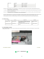
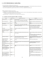

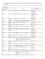
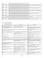
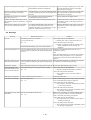
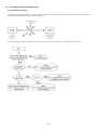

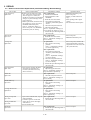
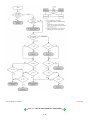
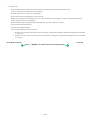
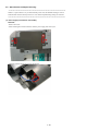

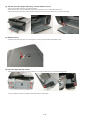
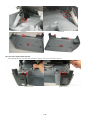
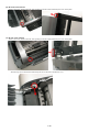
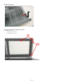
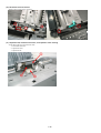
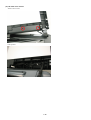
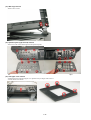
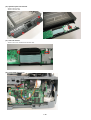

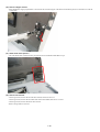
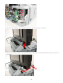
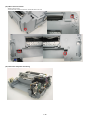
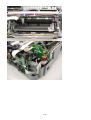
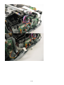

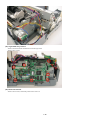
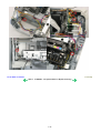
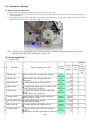
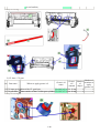
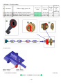
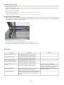
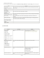
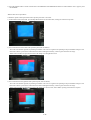
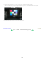
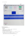
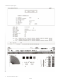
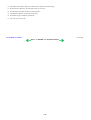
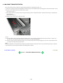


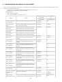

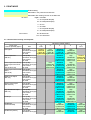
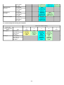
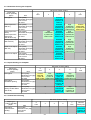
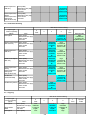
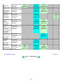
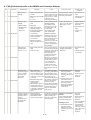
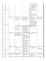

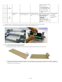
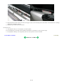

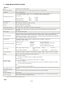
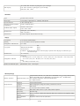
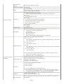
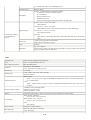
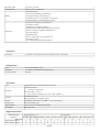


![02_MB63D_[IT]_1230UK_DVB](http://vs1.manualzilla.com/store/data/006148355_1-c6a5245fcda1cbc74e11828fafaed889-150x150.png)