1
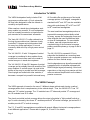
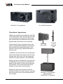
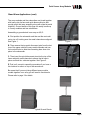
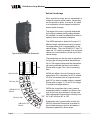
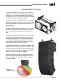
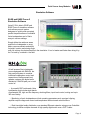
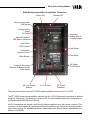
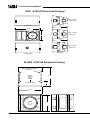
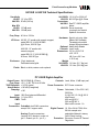
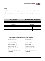
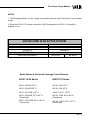
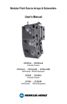
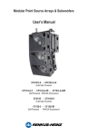
Modular Point Source Array Modules Associated 15 Inch Subwoofer VA101-7 & VAX101-7 Series VA101-15 & VAX101-15 Series VA101-22 & VAX101-22 Series VA15S & VAX15S Subwoofer Users Manual Point Source Array Modules Introduction To VARIA The VARIA loudspeaker family includes 3 fullrange array modules and a 15 inch subwoofer. All have been designed to offer the ultimate in versatility and performance. When used as a stand alone loudspeaker each array module is a powerful 10 inch loudspeaker that can be easily mounted on a tripod stand or pole mounted on the associated subwoofer. All 3 models offer a wide range of horizontal coverage options. A 90 degree waveguide is standard but 60o and 120o are also available along with revolutionary 60o to 90o and 120o to 90o transitional waveguides. The Varia VA / VAX101-7 is often referred to as the long throw module since it features closely controlled 7.5 degree vertical dispersion ideal for many long throw applications. It is most commonly used at the top of high power vertical arrays. The new transitional waveguides produce a trapezoidal coverage pattern ideally suited for many square and rectangular rooms and often eliminate the need for additional side or down fill loudspeakers. For more details on these new and unique devices and a complete listing of the horizontal coverage patterns available please go to page 6 and to page 21. The VA / VAX101-15 with 15 degrees of vertical coverage is considered to be a medium throw module and is most often used in the center of vertical arrays or in stand alone systems. The VA / VAX15S is a powerful 15 inch subwoofer that doubles as a mounting base for floor mounted systems or as a suspension platform for flown vertical arrays. The VA / VAX101-22 has 22.5 degrees of vertical coverage and is probably the most versatile of the array modules. In vertical arrays it is used at the bottom of the array to provide near field coverage, Stood upright and mated with other modules, it becomes a compact but powerful horizontal array. Varia loudspeakers may be self powered with a powerful built-in bi-amplifier equipped with RHAON digital signal processing, control and supervision or they may be a passive unit that relies on external amplification and includes a passive cross-over. The VARIA Concept The VARIA approach is based on the use of 3 different shape cabinets each having a vertical coverage pattern that is complementary to the cabinet shape. Thus, the VA/VAX101-7 has 7.5º sides and 7.5º vertical coverage. The -15 modules have 15o sides and provide 15o coverage and the -22 modules have 22.5o sides. The closely controlled vertical coverage allows the output of modules in "tight packed"vertical arrays" to sum coherently; thus three 15o modules provide 45o of vertical coverage, just as two 22.5 modules provide 45o of vertical coverage. The 7.5, 15 and 22.5 waveguides are available with several different horizontal coverage patterns to suit different applications. Please refer to pages 19, 21 and 23 for details. Page 2 Point Source Array Modules The VARIA Hardware Concept The array modules have heavy metal side channels and each module is provided with 2 heavy joining bars (one for each side) and associated quick release pins so it can easily be stacked with similar modules For example , -7 modules with other -7 modules. Joining unlike modules, for example joining -7 modules with -15 modules requires special joining bars, called "biscuits". See list below. Part Number Used to Join ICB-VA101-715 VA/VAX101-7 to VA/VAX101-15 ICB-VA101-722 VA/VAX101-7 to VA/VAX101-22 ICB-VA/101-1522 VA/VAX101-15 to VA/VAX101-22 The VA /VAX15S subwoofer uses the same technique, only it has 2 metal channels on each side of the cabinet, one towards the rear and one towards the front. The two in the front channels are hinged to allow the subwoofer to be used with either -7, -15 or -22 array modules. The connecting bars in the rear channels are simple single piece bars. Their purpose is to help lock two subwoofers firmly together when they are stacked. Table of Contents Introduction to VARIA 2 Stand Alone Applications 4 Ground Stacked & Pole Mounted Systems 4 Vertical Line Arrays6 Horizontal Arrays8 EASE Focus and RHAON 9 High Frequency Control Settings 10 Rear Panel Connections 11 Tech. Specs VA /VAX101-7, -15 -22 Array Modules 12 Dimensional Information14 Tech Specs VA / VAX15S Subwoofer 15 DSP Settings for VA /VAX101-7 & VA / VAX15S 16 DSP Settings for VA /VAX101-15 & VA / VAX15S 18 DSP Settings for VA /VAX101-22 & VA / VAX15S 20 Safety Warnings22 Page 3 Point Source Array Modules VA/VAX101-7 Array Module VA / VAX15S Subwoofer “Stand Alone” Applications VARIA array modules are equipped with dual Metric M10 attachment points top and bottom so they can be easily flown using eye bolts. Multi-angle pole sockets bottom mounted and side mounted flying hardware add further to their versatility. The associated 15-inch subwoofer has top and bottom mounted M20 threaded pole sockets and side mounted flying hardware allowing it to be used as a base for array modules either with or without a pole. Multi-angle pole socket Threaded adjustable pole Threaded 20 mm pole sockets on the subwoofers and the multi-angle pole sockets on the full range cabinets allow one or two of the full range array modules to be pole mounted on the subwoofers. Safety is always a consideration in any setup and consideration must be given to the strength and stability of the surface on which the ground stack will be placed. Pole mounted stacks should be limited to no more than 2 array modules. Multiple full range array modules can also be stacked on the ground or floor without a mounting pole using one or more of the matching subwoofers as a base. Page 4 VA/VAX101-7 Array Module pole mounted on VA/VAX15S 15” Subwoofer Point Source Array Modules Stand Alone Applications (cont) The array modules and the subwoofers are joined together with heavy-duty tie bars and quick-disconnect pins that provide quick and easy assembly along with metal-to-metal reliability. Ground stacks of this type can easily handle up to 3 array modules and two subwoofers. Assembling a ground stack is as easy as A,B,C. A. First position the subwoofer and then set the next cabinet on top of it making sure the metal channels are aligned See Figure 1. Figure 1 B. Then remove the top quick disconnect pins from the bottom of the upper cabinet’s heavy metal channels and use the knurled knobs to slide the connecting bars down into place in the subwoofer. C. Then insert the quick disconnect pins into the top of the lower cabinet’s metal channels to secure the tie bars in place and bind the cabinets together. See Figure 2. D That is all, except to repeat the procedure if you have a third cabinet to mount on top of the second one. Figure 2 Be aware that if you are joining different array module models together in an array you will need to use biscuits. Please refer to page 3 for details. Typical Ground Stacks Page 5 Point Source Array Modules Vertical Line Arrays Most vertical line arrays are not assembled in a straight line as their name implies. Instead they are constructed in either a curved or a J shape or a combination of both shapes to obtain the proper sound coverage. The shape of the array is typically determined by the flying hardware and the splay between the cabinets can easily be different than what is optimum from an acoustical standpoint. Typical Array Flown from Subwoofer Sub "-7" "-7" ICB-VA101-715 Biscuit Std Conn. Bar ICB-VA101-715 Biscuit Page 6 The subwoofers can also be used as a platform for flying the full range modules beneath them. Up to 6 full range modules and two subwoofers can easily and safely be flown in this fashion. Please refer to page 3 for a list of connecting bars. VARIA also offers a choice of horizontal coverage patterns; 90º is standard, but 60º is offered for when the audience are is long and narrow and 120º for when a broader pattern is needed. Please refer to pages 17, 19 and 21 for listings of available coverage patterns. Std Conn. Bar Std Conn. Bar The VARIA approach is based on the use of 3 different shape cabinets each having a vertical coverage pattern that is complementary to the cabinet shape. Thus, the VA/VAX101-7 has 7.5º sides and 7.5º vertical coverage. As a long throw cabinet, its normal position is at the top of multicabinet arrays. VARIA also recognizes that in many cases a trapezoidal pattern is needed; one wider in the front of the room and narrower in the rear and "-15" offers waveguides that transition smoothly from "-22" 60º to 90º and from 90º to 120º. "-15" Subwoofers aren’t ignored either and the VA/ VAX15S subwoofer that served as a base for ground stacked arrays can also be used as a suspension platform for flown arrays Point Source Array Modules Assembling Vertical Line Arrays 1. Attach the RHANG101LA Flybar to the top cabinet using the quick release pins. Note the bridle construction which allows you to move the suspension bar laterally and adjust the array’s tilt (aiming angle). Move the bridle toward the rear of the cabinets for more tilt. If you are using a VA / VAX15S subwoofer as a suspension platform, you will also need to remove the four feet from the sub to allow it and the top array module to fit snugly together. 2. Attach the lifting device (chain hoist, fork lift, etc) you will use to raise the cabinet into position to the flybar. One commonly used arrangement is shackles and a sling. 3 Raise the cabinet high enough to let you roll or slide the next cabinet into position beneath it and lower the first cabinet into position over the second cabinet and use the quick release pins and joining bars to lock the two cabinets together. Move the joining bars from the upper cabinet down into the lower cabinet. 5. Repeat the procedure until the array is complete and then lift (hoist) the array into position and secure it. Note that you will need to use special connecting bars called biscuits to join two unlike array modules, such as the 7.5 degree -7 and the 15 degree -15 modules. Transitional wave guides are also available to assist in shaping the array's horizontal coverage to fit the audience area without introducing discontinuities between the array modules. Transitional Coverage Balloon Page 7 Point Source Array Modules Assembling Vertical Line Arrays (continued) 1 2 3 One of the situations you may run into is you want to use a number of 7.5 degree modules at the top of a tall vertical array , but the 7.5 degree tilt provided when two -7 modules are tight packed provides to much tilt. Fortunately, the VA101-7's connecting bar is hinged and allows you to vary the aiming angle from 7.5 degrees down to 0 degrees in half degree steps. The assembly procedure is the same as the one outlined on the previous page. The difference is in the adjustable connecting bar. One end of it is on a swivel and the bar has more location holes than the normal connecting bar. See drawing below. This allows you to raise and lower the rear of the cabinet to change its aiming angle. 1. Decide what aiming angle you need and from the chart on the metal channel determine which numbered hole location you should use. 2. Remove the quick disconnect pin that is holding the hinged connecting bar in position and use the knurled knob to move the bar down to that location and insert the quick disconnect pin into the bar to lock it in position. 3. Move the next VA101-7 loudspeaker module into place, remove its top quick disconnect pin and then lower the upper cabinet(s) into position. Use the chart on the metal channel to to pick the correct lettered insertion Location to use. You may want to physically lift the rear of the lower cabinet to help with the alignment. 0° = A1 1.5° = B1 3.0° = C1 4.5° = A3 6.0° = B3 7.5° = C3 5. Insert the quick disconnect pin and continue adding cabinets. A B C VA101-7 metal channel Page 8 Hinged connecting bar Point Source Array Modules This page intentionally left blank for future expansion of ground stacking instructions Page 9 Point Source Array Modules Horizontal Arrays The skillful design, complementary cabinet angles and tightly controlled dispersion that allow the sonic outputs of VARIA array modules to be smoothly mixed to obtain the desired coverage perform just as well in horizontal arrays as they do in vertical line arrays. R-HANG-VA101H Joining two VA101-22 22.5º modules together in a horizontal array or cluster produces a seamless 45º horizontal pattern; use three 22.5º modules for 67.5º of horizontal coverage and 4 for 90º. Or use 6 VA10122 modules for 135º of horizontal coverage. Assembly is a snap. Stand the cabinets on end, use the joining bars to tie them together and then attach R-Hang bars to the array and hoist it into place. Use a single RHANG-VA101H bar for two cabinets,two for 3 to 5 cabinet horizontal arrays and more for even larger horizontal arrays. Note that the RHANG-VA101H flying hardware accommodates only the 22.5 degree VA / VAX101-22 You should not attempt to use it with the other Varia array modules. Warning: The actual rigging of loudspeakers suspended from a truss or from a ceiling is a serious undertaking that is beyond the scope of this document. It should be done only by qualified and experienced professionals using only load rated hardware. We strongly recommend that you have your design reviewed and approved by a licensed structural engineer who can also verify the suitability of the building attachment points. Renkus-Heinz is not responsible for any non Renkus-Heinz products or for any misuse of Renkus-Heinz products. Page 10 Typical Horizontal Array Point Source Array Modules Simulation Software EASE and EASE Focus II Simulation Software Varia101 GLL data in EASE and EASE Focus II simulation software tools allows you and system designers to quickly and accurately predict the performance of individual Varia loudspeakers and of Varia arrays in various settings. Simply define the audience areas, position the loudspeaker or array, add or remove cabinets and adjust its height, location and aiming angle until you achieve the desired results in the simulation. It is a lot easier and faster than doing it by the "cut and try” method in the field. All self-powered Varia loudspeakers are equipped with RHAON, the first practical system to combine individual loudspeaker control and supervision of self-powered loudspeaker systems with digital audio distribution. RHAON puts you in total control of: – A powerful DSP inside each Varia loudspeaker that includes eight bands of parametric EQ, high and low frequency shelving filters, input level control, muting and up to 340 ms of delay. – Monitoring of each loudspeakers critical operating parameters such as signal clipping, amplifier output voltage and current and temperature with automatic alert functions. – Real time digital audio distribution over standard Ethernet networks using proven CobraNet technology to deliver multiple channels of high quality digital audio over a CAT 5 cable. Page 11 Point Source Array Modules Rear Panel Connections & Controls VAX101 Connections Screw Terminal Strip Inputs Looping In & Out Neutrik 4-Pin Speakon Connectors Array Module High Frequency Control Not all setups are identical and neither are all rooms. That is why the VAX series non-powered array modules include a rear mounted high frequency level control. The high frequency level control allows you to adjust the high frequency output of each array module to compensate for: 1. the increased loss of high frequency energy from air loss over distance 2. the increased coupling between array modules at low frequencies 3. different room sizes and acoustics They allow you to maintain the proper High/Mid/Low frequency balance throughout the listening area. As a general rule use “Flat” when working with a single cabinet, plus 6 when using 2 cabinets in a small array and plus 9 in arrays having 3 or more cabinets. Page 12 High Frequency Level Control Point Source Array Modules RHAON Empowered VARIA Array Module Connections Power LED Thermal LED Primary Analog Input XLR female Looping Analog Output XLR male Secondary Analog input & Looping Output Signal & Overdrive LED Status Indicators Input Pad & LED Indicator Fault Detect Push Button Volume Controls Fault Relay Mute Buttons AC Power On/Off Switch Primary & Secondary Ethernet (CobraNet) Inputs RJ-45 female AC Line Voltage Selector AC Line Fuse IEC Power Connector The input panel shown is for the PF2-500R digital bi-amplifier used in the VA101-7-52R The PF1-500R single channel amplifier used with the VA / VAX15S subwoofer input panel is identical except for having only 1 mute switch and status LED. For more detailed information, please refer to the Renkus-Heinz RHAON User’s Manual. VAX15S subwoofers are shipped wired for fully passive operation using the internal crossover. The crossover can be bypassed by removing the connector plate from the cabinet and changing several internal connections. For detailed instructions, please refer to the Renkus-Heinz Loudspeaker User’s Manual, form RH508. Page 13 Point Source Array Modules VA101-x-52R & VAX101-x Array Modules Technical Specifications Sensitivity VA101-x-52R: 1.0 V for RPO VAX101-x: 96 dB (1W/1m) Freq. Range: 60 Hz to 20 kHz Max SPL: 126 dB peak @ 1 meter HF Driver: VA / VAX 101-7 & VA / VAX101-15 (2) VA / VAX101-22 (1) 1” HF driver, RH model SSD1750-TN 75 W RMS, 150 W Pgm Woofers: VA101-R: 10” woofer; RH SSL10-7-4, 250 W RMS @ 4 Ohms, 500 W Pgm VAX101: 10” woofer; RH SSL10-7, 250 W RMS @ 8 Ohms, 500 W Pgm Finish: Black, white; custom colors optional Pwr. Rating: 500 W @ 4 Ohms Horiz. Dispersion: 90° standard, 60°, 120°, transitional 60° to 90° & 90° to 120 °available Vert. Dispersion: 7.5 º, 15° and 22.5° models available Controls: Level, Mute, 10 dB Input Pad Connectors: Looping 4-pin Neutrik Speakon Terminal strips. Dimensions: 23 3/4” W x 13” H x 15” D, (60.3 cm x 33 cm x 38 cm) Weights : VAX101-7: VA101-7-52R: VAX101-15: VA101-15-63R: VAX101-22: VA101-22-52R: 64 Lbs 68 Lbs 59 Lbs 63 Lbs 63.5 Lbs 67.5 Lbs (29 .0kg) (30.8 kg) (26.8 kg) (28.6 kg) (28.8 kg) (30.6 kg) Enclosure: Multi-ply hardwood Perforated steel grille Hardware: 4 point universal mounting hardware Multi-angle pole socket Side mounted flying hardware Page 14 Point Source Array Modules PF2-500 Digital Amplifier Technical Specifications Output Power: LF: 500 W RMS @ 4 Ohms HF: 100 W RMS @ 4 Ohms Freq. Resp: +0.0, -.5 dB, 20 Hz to 20 kHz THD Distortion: < 0.02% typical Hum & Noise: <100 dB (A weighted) Damping: >100 Input: 10K Ohm balanced differential Sensitivity: 1.0 V for RPO CMR: 74 dB Input Connectors CobraNet; Dual RJ45 connectors; accept Cat 5 copper cable. Analog Looping XLR; female in, male out, (pin 1 chassis, pin 2 +, pin 3 -) Phoenix connectors Controls: evel, Mute, 10 dB Input Pad Pwr. Connector: IEC Power connector Power Input: Switchable, 115 or 230 V AC, 50/60 Hz Power 5 A @ 120 V, 2.5 A @ 240 V Idle current: 400 ma @120 V; 200 ma @ 240 V Max inrush current: 1 A Digital Format: 16, 20 or 24 bit PCM 48 or 96 kHz sample rate Selectable network latency Page 15 Point Source Array Modules VA101 & VAX101 Dimensional Drawings VA101-22-52R VAX101-22 Top View 15” 23 3/4” VA101-15-52R VAX101-15 13” 15” Front View VA101-22-52R VAX101-22 End Views Bottom View VA15S-R & VAX15S Dimensional Drawing Metric M10 Attachment Points (typical for 8) 22 1/2” Treaded Pole Socket 6 1/8” 23 3/4 “ 19” Page 16 Point Source Array Modules VA15SR & VAX15S Technical Specifications VA15S-5R: 115 V AC or 230V AC VAX15S: 800 W Pgm @ 8 Ohms Connectors: VA15S-5: See PF1-500R amplifier below VAX15S: Screw terminals, Looping 4-pin Neutrik Speakon connectors Sensitivity VA15S: 1.0 V for RPO VAX15S: 97 dB (1W/1m) Max SPL VA15S: 127 dB peak VAX15S: 129 dB peak Freq. Resp: 40 Hz to 120 Hz LF Driver: VA15S: 15” woofer with ceramic magnet, model SSL15-14; 400 W RMS @ 4 Ohms, 800 W Pgm VAX15S: 15” woofer with ceramic magnet, model SSL15-17; 400 W RMS @ 8 Ohms, 800 W Pgm Enclosure: 13-ply hardwood, Perforated metal grille Finish: Black or white; custom color optional Hardware: 8-point univ. mtg. hdw. (Metric M10 threads) Threaded pole socket Integral flying hardware Optional: Heavy duty wheels Controls: Level, mute Dimensions: 19” H x 23 3/4” W x 22 1/2” D (48.3 cm x 60.3 cm x 56.5 cm) Weight VA15S-5R: 114 Lbs (51.7 Kg) net VAX15S: 112 Lbs (50.8 Kg) net PF1-500R Digital Amplifier Output Power: Freq. Resp: THD Distortion: Hum & Noise: Damping: 500 W RMS @ 4 Ohms +0.0, -.5 dB, 20 Hz to 20 kHz < 0.02% typical <100 dB (A weighted) >100 Input: 10K Ohm balanced differential Sensitivity: 1.0 V for RPO CMR: 74 dB Controls: Level, Mute, 10 dB input pad Power Connector: IEC Power connector Power: Switchable, 115 or 230 V AC, 50/60 Hz 5 A @ 120 V, 2.5 A @ 240 V Idle current: 400 ma @120 V 200 ma @ 240 V Max inrush current: 1 A Input Connectors: CobraNet; dual RJ45 connectors; Digital Format: accept Cat 5 copper cable. ; Analog: Phoenix connectors Looping XLR; female in, male out Protection: (pin 1 chassis, pin 2 +, pin 3 -) 16. 20 or 24 bit PCM; 48 or 96 kHz sample rate selectable Network Latency. Soft & Peak Limiting Excursion Control & Thermal Regulation Page 17 Page 18 AMP GAIN OUTPUT DELAY POLARITY CROSSOVER CENTER FREQUENCY TYPE SLOPE EQ #1 CENTER FREQUENCY Bandwidth BOOST/CUT EQ #2 CENTER FREQUENCY Bandwidth BOOST/CUT EQ #3 CENTER FREQUENCY Bandwidth BOOST/CUT EQ #4 CENTER FREQUENCY Bandwidth BOOST/CUT VAX101-7 2.7 kHz .3 -2 dB 4.5 kHz .6 +2 dB 13 kHz .7 +9 dB 570 Hz 0.4 -3.0 dB 1 kHz 0.4 -4.0 dB NONE NONE NONE 1.7 kHz HP LINKWITZ-RILEY 24 dB/ Oct 1.5 kHz .3 3 dB 1.6 kHz LP LINKWITZ-RILEY 24 dB/ Oct -11 dB NONE NORMAL HF 125 Hz 0.4 4.0 dB 60 Hz HP BUTTERWORTH 24 dB/ Oct 0 dB 0.530mS NORMAL LF WIRED AS BI-AMP NONE NONE NONE Point Source Array Modules VAX101-7 & VAX15S DSP Settings Suggested DSP settings for VAX101-7 line array modules and their companion VAX15S subwoofer combinations appear below and on the next page. Note that these would not apply to self-powered VA101-7 modules with their built-in DSP. Point Source Array Modules NOTES: 1. The EQ settings shown are for a single array module and may need “fine tuning” in multi cabinet arrays. 2. When the VAX101-7 is being used with a VAX15S subwoofer the VAX101-7 should be delayed 2.7 ms. VAX15S WIRED AS ACTIVE AMP GAIN OUTPUT DELAY POLARITY CROSSOVER CENTER FREQUENCY TYPE SLOPE 0 dB NONE NORMAL 40 Hz HP BUTTERWORTH 24 dB/ Oct 80 Hz LP BUTTERWORTH 18 dB/ Oct Model Number & Horizontal Coverage Cross Reference VA101-7-52 Series VAX101-7 Series VA101-7/6-52R: 60o H VA101-7/9-52R: 90o H VA101-7/12-52R: 120o H VAX101-7/6: 60o H VA101-7/69-52R: 60o to 90o H (Transitional) VA101-7/912-52R: 90o to 120o H (Transitional) VAX101-7/69: 60o to 90o H (Transitional) VAX101-7/912: 90o to 120o H (Transitional) VAX101-7/9: 90o H VAX101-7/12: 120o H Page 19 Page 20 AMP GAIN OUTPUT DELAY POLARITY CROSSOVER CENTER FREQUENCY TYPE SLOPE EQ #1 CENTER FREQUENCY Bandwidth BOOST/CUT EQ #2 CENTER FREQUENCY Bandwidth BOOST/CUT EQ #3 CENTER FREQUENCY Bandwidth BOOST/CUT EQ #4 CENTER FREQUENCY Bandwidth BOOST/CUT VAX101-15 2.2 kHz .250 -3 dB 3.2 kHz .7 -3.0 dB 13 kHz .7 +9 dB 520 Hz 0.4 -1.5 dB 1.1 kHz .5 -4.0 dB 1.8 kHz .3 2.0 dB 1.7 kHz HP LINKWITZ-RILEY 24 dB/ Oct 1.7 kHz .3 3 dB 1.7 kHz LP LINKWITZ-RILEY 24 dB/ Oct -11 dB NONE NORMAL 125 Hz 0.4 4.0 dB 60 Hz HP BUTTERWORTH 24 dB/ Oct 0 dB 0.530mS NORMAL WIRED AS BI-AMP LF HF NONE NONE NONE Point Source Array Modules VAX101-5 & VAX15S DSP Settings Suggested DSP settings for VAX101-15 line array modules and their companion VAX15S subwoofer combinations appear below and on the next page. Note that these would not apply to self-powered VA101-15 modules with their built-in DSP. Point Source Array Modules NOTES: 1. The EQ settings shown are for a single array module and may need “fine tuning” in multi cabinet arrays. 2. When the VAX101-15 is being used with a VAX15S subwoofer the VAX101-15 should be delayed 2.7 ms. VAX15S USED IN AN ACTIVE SYSTEM AMP GAIN OUTPUT DELAY POLARITY CROSSOVER CENTER FREQUENCY TYPE SLOPE 0 dB NONE NORMAL 40 Hz HP BUTTERWORTH 24 dB/ Oct 80 Hz LP BUTTERWORTH 18 dB/ Oct Model Number & Horizontal Coverage Cross Reference VA101-15-52 Series VAX101-15 Series VA101-15/6-52R: 60o H VA101-15/9-52R: 90o H VA101-15/12-52R: 120o H VAX101-15/6: 60o H VAX101-15/9: 90o H VA101-15/69-52R: 60o to 90o H (Transitional) VA101-15/912-52R: 90o to 120o H (Transitional) VAX101-15/69: 60o to 90o Hl (Transitional) VAX101-15/912: 90o to 120o H (Transitional) VAX101-15/12: 120o H Page 21 Page 22 AMP GAIN OUTPUT DELAY POLARITY CROSSOVER CENTER FREQUENCY TYPE SLOPE EQ #1 CENTER FREQUENCY Bandwidth BOOST/CUT EQ #2 CENTER FREQUENCY Bandwidth BOOST/CUT EQ #3 CENTER FREQUENCY Bandwidth BOOST/CUT EQ #4 CENTER FREQUENCY Bandwidth BOOST/CUT VAX101-22 2.6 kHz .4 -4 dB 4.7 kHz .35 -1.5 dB 13 kHz .7 +9 dB 520 Hz 0.4 -1.5 dB 1.1 kHz .5 -4.0 dB 1.8 kHz .3 2.0 dB 1.6 kHz HP LINKWITZ-RILEY 24 dB/ Oct 1.7 kHz .3 4 dB 1.7 kHz LP LINKWITZ-RILEY 24 dB/ Oct -7.5 dB NONE NORMAL 125 Hz 0.4 4.0 dB 60 Hz HP BUTTERWORTH 24 dB/ Oct 0 dB 0.530mS NORMAL WIRED AS BI-AMP LF HF NONE NONE NONE Point Source Array Modules VAX101-22 & VAX15S DSP Settings Suggested DSP settings for VAX101-22 line array modules and their companion VAX15S subwoofer combinations appear below and on the next page. Note that these would not apply to self-powered VA101-22 modules with their built-in DSP. Point Source Array Modules NOTES: 1. The EQ settings shown are for a single array module and may need “fine tuning” in multi cabinet arrays. 2. When the VAX101-22 is being used with a VAX15S subwoofer the VAX101-22 should be delayed 2.7 ms. VAX15S WIRED AS ACTIVE AMP GAIN OUTPUT DELAY POLARITY CROSSOVER CENTER FREQUENCY TYPE SLOPE 0 dB NONE NORMAL 40 Hz HP BUTTERWORTH 24 dB/ Oct 80 Hz LP BUTTERWORTH 18 dB/ Oct Model Number & Horizontal Coverage Cross Reference VA101-22-52 Series VAX101-22 Series VA101-22/6-52R: 60o H VA101-22/9-52R: 90o H VA101-22/12-52R: 120o H VAX101-22/6: 60o H VAX101-22/9: 90o H VA101-22/69-52R: 60o to 90o H (Transitional) VA101-22/912-52R: 90o to 120o H (Transitional) VAX101-22/69: 60o to 90o Hl (Transitional) VAX101-22/912: 90o to 120o H (Transitional) VAX101-22/12: 120o H Page 23 IMPORTANT SAFETY INSTRUCTIONS 1. Read these instructions. 2. Keep these instructions. 3. Heed all warnings. 4. Follow all instructions. 5. Do not use this apparatus near water. 6. Clean only with dry cloth. 7. Do not block any ventilation openings. Install in accordance with the manufacturer’s instructions 8. Do not install near any heat sources such as radiators, heat registers, stoves, or other apparatus (including amplifiers) that produce heat. 9. Do not defeat the safety purpose of the polarized or grounding-type plug. A polarized plug has two blades with one wider than the other. A grounding type plug has two blades and a third grounding prong. The wide blade or the third prong is provided for your safety. If the provided plug does not fit into your outlet, consult an electrician for replacement of the obsolete outlet. 10. Protect the power cord from being walked on or pinched particularly at plugs, convenience receptacles, and the point where they exit from the apparatus. 11. Make sure the power cord remains readily accessible at all times. 12. Only use attachments/accessories specified by the manufacturer. 13. Unplug this apparatus during lightning storms or when unused for long periods of time. 14. Refer all servicing to qualified service personnel. Servicing is required when the apparatus has been damaged in any way, such as power-supply cord or plug is damaged, liquid has been spilled or objects have fallen into the apparatus, the apparatus has been exposed to rain or moisture, does not operate normally, or has been dropped. Graphic Symbols The lightning flash with arrowhead symbol, within an equilateral triangle, is intended to alert the user to the presence of uninsulated “Dangerous Voltage” within the product’s enclosure that may be of sufficient magnitude to constitute a risk of electric shock to humans. The exclamation point, within an equilateral triangle is intended to alert the users to the presence of important operating and maintenance (servicing) instructions in the literature accompanying the product. “WARNING - TO REDUCE THE RISK OF FIRE OR ELECTRIC SHOCK, DO NOT EXPOSE THIS APPARATUS TO RAIN OR MOISTURE” “CAUTION: THESE SERVICING INSTRUCTIONS ARE FOR USE BY QUALIFIED SERVICE PERSONNEL ONLY. TO REDUCE THE RISK OF ELECTRIC SHOCK DO NOT PERFORM ANY SERVICING OTHER THAN THAT CONTAINED IN THE OPERATING INSTRUCTIONS UNLESS YOU ARE QUALIFIED TO DO SO”. Renkus-Heinz, Inc., 19201 Cook Street, Foothill Ranch, CA 92610-3501, USA Tel: 949-588-9997 • Fax: 949-588-9514 • [email protected] • www.renkus-heinz.com RH 773 Rev A April 2013