1
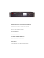
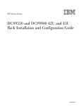
EXPANDABLE DC POWER SUPPLY
N+1 DC Power System
with Battery Backup / Charging Function
MODELS :
SEC-40BRM
SEC-60BRM
SEC-80BRM
SEC-100BRM
INSTALLATION & OPERATING MANUAL
Please read this manual before operating your power supply.
•
PROVIDES N + 1 REDUNDANCY
•
ALLOWS CONNECTION OF EXTERNAL BATTERIES FOR BACKUP
•
EXPAND OUTPUT POWER BY ADDING POWER MODULES
•
UP TO 100 AMPS CONTINUOUS POWER
•
VOLT / AMPERE METER
•
OPERATION STATUS L.E.D.
•
FAN FAILURE ALARM AND WARNING L.E.D.
•
REMOTE MONITORING AND INDICATION
•
19” RACK MOUNT
•
2 YEAR WARRANTY / TOLL FREE TECHNICAL SUPPORT
TABLE OF CONTENTS
Topic
Page
Important safety instructions
1,2
Description and application
3
Design and principle of operation
3
Cooling and warning for fan failure
3
Front panel controls and indicators
4
Rear panel controls
4,5
Protections
5
Installation and operation
6
Operation of battery back-up
7
Output voltage adjustment
8,9
Installation and removal of modules
9,10
Trouble shooting
11,12
Limiting electromagnetic interference
13,14,15
Specifications
16
Appendix :
17,18
Figures 1 to 3
Warranty information
19
Notes
20
IMPORTANT SAFETY INSTRUCTIONS
Please read before using your power supply.
CAUTION !
ALL ELECTRICAL INSTALLATIONS MUST MEET LOCAL AND NATIONAL WIRING CODES AND SHOULD BE PERFORMED BY A QUALIFIED ELECTRICIAN.
OPERATION OF COOLING FAN
THE HEAT PRODUCED IS EXTRACTED BY 2 FANS. IN CASE ANY OF THE FANS
FAILS, LIGHT AND SOUND ALARMS WILL BE ACTIVATED. IMMEDIATELY
SWITCH OFF THE POWER TO THE UNIT TO PREVENT DAMAGE DUE TO OVER
HEATING
CONNECTION TO AC OUTLET
THE POWER SUPPLY SHOULD BE OPERATED ONLY FROM A STANDARD 3
PIN 120 V AC/ 60 HZ OUTLET WITH PROPER GROUNDING CONNECTION.
SEC-100BRM MUST BE POWERED FROM A 30A BRANCH CIRCUIT AND
SHOULD BE PLUGGED INTO A 30A AC RECEPTACLE WHICH WILL ACCEPT
THE 30A NEMA L5-30P PLUG OF THE POWER CORD. SEC-80BRM MUST BE
POWERED FROM A 20A CIRCUIT AND MUST BE PLUGGED INTO A 20A AC
OUTLET WHICH WILL ACCEPT THE 20A NEMA 5-20P PLUG PROVIDED WITH
THE POWER CORD. SEC-60BRM AND SEC-40BRM MAY BE POWERED FROM
A 15A CIRCUIT. ALTHOUGH SEC-60BRM & SEC-40BRM ARE PROVIDED WITH
20A, NEMA 5-20P PLUG, THESE MAY BE POWERED FROM A 15A BRANCH CIRCUIT IF 20A BRANCH CIRCUIT IS NOT AVAILABLE. FOR THIS SITUATION, A
SEPARATE 15A, NEMA 5-15P PLUG HAS BEEN PROVIDED TO REPLACE THE
20A, NEMA 5-20P PLUG PROVIDED WITH THE POWER CORD.
CAUTION !
PLUG REPLACEMENT SHOULD BE DONE BY A QUALIFIED
ELECTRICIAN. PLEASE ENSURE PROPER POLARITY OF THE CONNECTIONS
AS FOLLOWS :
“ L ” LINE
“ N ” NEUTRAL
EARTH GROUND
BLACK WIRE
WHITE WIRE
GREEN WIRE
DO NOT USE EXTENSION CORD UNLESS ABSOLUTELY NECESSARY. IF AN
EXTENSION CORD MUST BE USED , MAKE SURE :
1.
THE PINS ON THE EXTENSION CORD'S PLUG ARE OF THE SAME NUMBER, SIZE AND SHAPE AS THOSE OF THE PLUG OF THE POWER SUPPLY
CORD. NEVER USE AN EXTENSION CORD WITH A 2 PIN PLUG ( THERE
WILL BE NO GROUNDING CONNECTION IN THIS TYPE OF PLUG WHICH IS
A SHOCK AND FIRE HAZARD )
2.
THE EXTENSION CORD WIRE SIZE SHOULD BE MINIMUM 12 AWG, 20 A.
1.
LOAD AND BATTERY CONNECTIONS
THE LOAD & BATTERY TERMINALS ON THE POWER SUPPLY HAVE A TUBULAR HOLE OF DIAMETER 8mm (0.31”) WITH A SET SCREW.
ALWAYS ENSURE THAT THE CONNECTIONS ARE SECURE AND THE SCREWS
ARE TIGHTENED PROPERLY.
LOOSELY TIGHTENED CONNECTIONS RESULT IN EXCESSIVE VOLTAGE
DROP AND MAY CAUSE OVERHEATED WIRES AND MELTED INSULATION.
THE ENDS OF THE CABLES TO BE CONNECTED TO THE LOAD AND BATTERY
TERMINALS ON THE POWER SUPPLY SHOULD HAVE PIN TYPE OF CONNECTOR FOR MAKING A FIRM CONNCECTON. 4 PIECES OF PIN TYPE CONNECTORS ARE ENCLOSED WITH THE POWER SUPPLY. CRIMP THESE TO THE
ENDS OF THE CABLES.
USE MULTI STRANDED WELDING TYPE CABLE OR BATTERY CABLE
(NEOPRENE SYNTHETIC INSULATION, 90oC). USE PROPER SIZE OF CABLE,
AS INDICATED BELOW, TO CONNECT ANY DEVICE TO THE POWER SUPPLY.
THESE CABLE SIZES ARE VALID WHEN THE DEVICE IS WITHIN 6 FT. DISTANCE FROM THE POWER SUPPLY. THICKER WIRING WILL BE REQUIRED
FOR LONGER DISTANCES. THINNER WIRES WILL CAUSE OVERHEATING
AND EXCESSIVE VOLTAGE DROP :
SEC-100BRM
SEC-80BRM
SEC-60BRM/SEC-40BRM
100 A
80 A
UP TO 60 A
# 2 AWG | UP TO
# 4 AWG | 6’
# 6 AWG | DISTANCE
ENSURE THAT THE AC POWER IS SWITCHED OFF WHEN ANY DEVICE IS BEING CONNECTED TO THE POWER SUPPLY.
DO NOT ALLOW THE ENDS OF THE POSITIVE AND NEGATIVE WIRES TO
TOUCH EACH OTHER.
FUSE REPLACEMENT
ENSURE PROPERLY RATED FUSE ( 250 V, 4A ) IS USED IN EACH OF THE
MODULES.
ENVIRONMENT
DO NOT EXPOSE POWER SUPPLY TO RAIN, SNOW OR WATER SPRAY
DIS-ASSEMBLY AND REPAIR
THE POWER SUPPLY SHOULD BE DISASSEMBLED OR REPAIRED BY A
QUALIFIED TECHNICIAN. INCORRECT REASSEMBLY OR REPAIR MAY RESULT IN A RISK OF ELECTRIC SHOCK OR FIRE WHICH MAY RESULT IN
PERSONAL INJURY AND PROPERTY DAMAGE.
2.
DESCRIPTION
This is a 19 inch, 2U height (3.5”) Rack Mount Power Supply which converts 120 V ,
60 Hz. AC power into regulated 14.2 V DC , +/- 1% (At module output*) delivering up
to a maximum of 100 A continuous ( up to 115 A surge ) with 5 Base Level PCB
Modules. There is provision to connect the power supply to an external battery for
backup power in the case of an AC power failure and re-charge the battery when AC
power resumes.
*Voltage at output terminals Load+ & Load- will be 13.8V nominal (Please see page 7 for explanation.)
APPLICATIONS
The unit is designed for the following applications:
1.
2.
3.
N+1 redundant systems
Future power level expansion
Uninterrupted DC output when used in conjunction with an external battery backup.
DESIGN AND PRINCIPLE OF OPERATION
The unit is designed using advanced switch-mode technology and active load share circuitry for high reliability, high efficiency and minimum size and weight. It is modular in construction consisting of up to 5 base level
PCB modules (referred to as “PSM” – Power Supply Module) that are connected in parallel with true current
sharing. Each PSM is a stand alone power supply which delivers up to a maximum of 20 A continuous. By
equalizing the output currents, uniform thermal stress of the individual PSM is ensured which has utmost
importance for long term reliability of electronic components. The operating principle of the current share
mechanism is to measure the output current of each PSM and to be able to modify the output voltages of the
PSMs until all the participating PSMs deliver equal output current. Typically, the output currents of the paralleled PSMs will be within 10% of each other at full output current. One of the modules automatically assumes
the role of a master and the others operate as slaves. Each PSM is required to be interconnected with one
another to a common “SHARE BUS” through a pair of parallel pins marked “JUMP 1” and jumper wires ( Fig.
1 and 2).
For proper operation of the current share control circuitry, a minimum load current is required to flow through
each PSM to produce adequate feed back signal. This minimum pre-load current is provided by the sum of
the currents drawn by the fans and by an internal static load resistor connected across the load output terminals. This internal pre-load current* is kept to the minimum to reduce dissipation.
* NOTE: It is likely that due to the drift in the pre-set values, the minimum internal preload current may
not be sufficient to provide adequate feedback signal strength resulting in shut down of one or more
modules when no external load is present (The associated PSM Status LED will flash and also, the
associated signal for remote indication will oscillate between High and Low). As soon as external
load is applied to the unit, the feed back signal strength will increase and the PSM(s) that were shut
down will also operate normally.
The output is delivered through an isolating Schottky diode to enable connection of external battery for uninterrupted DC power output. The external backup battery is kept charged by taper charging through a series
resistor.
•
•
•
•
SEC-100BRM has 5 PSMs of 20 A each providing a total of 100 A
SEC-80BRM has 4 PSMs of 20 A each providing a total of 80 A
SEC-60BRM has 3 PSMs of 20 A each providing a total of 60 A
SEC-40BRM has 2 PSMs of 20 A each providing a total of 40 A
COOLING AND WARNING FOR FAN FAILURE
The heat generated due to internal power dissipation is removed by forced cooling
through two high power D.C. fans mounted at the back of the unit which suck air from
the vents on the sides of the unit & blow outwards from the rear of the unit.
IT IS EXTREMELY IMPORTANT THAT THE DISCHARGE SIDE OF THE FANS
AND THE SUCTION SIDES OF THE VENT SLOTS ARE NOT BLOCKED.
3.
A warning circuit monitors the operational condition of the fans. In case of a fan failure, a
buzzer will sound and the red LED indicating “FAN FAILURE” will light up. The unit should be
switched off immediately and the defective fan should be replaced. NEVER LOAD THE UNIT
WHEN THERE IS AN AUDIBLE ALARM AND THE FAN FAILURE LED IS ILLUMINATED.
The 2 fans are rated for 12 V nominal and are powered from the output voltage of the modules.
A small Printed Circuit Board (PCB) located on the right corner towards the back of the unit is
used to monitor the fans for abnormal operating conditions viz. open circuit or overload condition due to obstructed rotor.
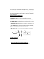
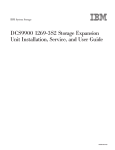
FRONT PANEL CONTROLS AND INDICATORS
The following controls and indicators are provided on the front panel :
1A. POWER ON/OFF SWITCH. The rocker switch will illuminate when switched on.
1B. BREAKER. A 25A circuit breaker provides protection on the input side against overload
2. VOLTMETER / AMMETER. A combined voltmeter and ammeter are provided. The function
can be switched by the Volt / Amp switch (3)
3. METER CHANGE-OVER SWITCH. Switches the combined meter between ammeter and
voltmeter
4. L.E.D “ PSM STATUS (1 to5)”. During normal operation, the green LED of each Power
Supply Module (PSM) will light. In case a power supply module (PSM) fails, its corresponding
LED will go off. LED 1 is for the left most module (near the on/off switch)
5. L.E.D “FAN FAILURE ”: In case of fan failure, this red LED lights up and a buzzer is
sounded.
1B.
5.
2.
1A.
4.
3.
REAR PANEL CONNECTORS
The following output connectors have been provided (Not shown).
1.
2.
Load+ (Positive), Load- (Negative) LOAD CONNECTORS.
For connecting to the D.C. Load
Battery+ (Positive), Battery- (Negative) BATTERY CONNECTORS.
For connecting external battery for un-interrupted D.C. power to the load.
4.
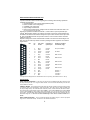
REMOTE MONITORING AND SIGNALLING
A provision has been made for remote signaling and monitoring of the following operational
conditions and parameters:
1. Operational status of the 5 Power Supply Modules (PSM)
2. Failure condition of the cooling fan(s)
3. Availability of AC input power
4. Output voltage measurement
5. Output current measurement ( Voltage across an internal shunt with Shunt ratio of 50
mV / 100 A or 0.5 mV per Amp)
Signaling of operational conditions as at serials 1, 2 and 3 above is opto coupled with open
collector, NPN transistor outputs. The collector and emitter of each opto coupled transistor are
accessible to the external user interface through the 25 pin D-Sub connector. Each open collector, opto coupled NPN transistor can provide a maximum of 50 mA with a collector to emitter
voltage of up to 35 V.
Outputs for voltage and current measurements at Serials 4 & 5 above are direct analogue voltages. The pin out of the 25 pin D-Sub connector providing the above signals for user interface
is given below:
Item
Pin
No.
Color Code
of Wire
Output Pin of
Opto-coupler
Operational Condition
or Parameter (High)
1
2
16
12
Black
White
Orange
Collector
Emitter
Collector
AC input is available
19
Green
Emitter
7
20
8
Gray
Violet
Violet
Collector
Emitter
Collector
21
Blue
Emitter
9
22
10
23
11
24
25
13
18
6
Blue
Green
Green
Yellow
Yellow
Orange
Red
Black
Gray
Blue
Collector
Emitter
Collector
Emitter
Collector
Emitter
-
2
3
4
5
6
7
8
9
Fan failure
PSM 1 Normal
PSM 2 Normal
PSM 3 Normal
PSM 4 Normal
PSM 5 Normal
Voltmeter +
Voltmeter * Ammeter +
* Ammeter -
* This signal is the voltage across an internal shunt at 0.5 mV per Amp (Shunt Ratio is 50 mV / 100 A)
PROTECTIONS
SHORT CIRCUIT PROTECTION: In the event of a short circuit, the PWM controller will be shut down and
the output will drop to near 0 V. The green LEDs will flash. The unit will reset automatically once the short
circuit condition is removed
CURRENT LIMITING: The unit will enter this mode when the load tries to draw more than the limiting values
of currents as shown in the specifications. Under this condition, there will be loss of voltage regulation and
the output voltage will drop. The “PSM STATUS” LEDs will, however, remain illuminated, but dimmed. When
the overload reaches approximately 140A for SEC-100BRM or 112A for SEC-80BRM or 84A for SEC-60BRM
or 56A for SEC-40BRM (the output voltage will be approximately 2.7V), the unit will shut down (will enter
hiccup mode). The PSM status LEDs will start flashing and PSM status signal for remote indication will oscillate between High and Low. The unit will reset automatically as soon as the overload condition is removed .
INPUT SURGE PROTECTION : The unit is protected against input voltage surges. In case of input spike/
surge, the A.C. side breaker will trip. The 4A fuse on the module will also blow.
5.
FAN FAILURE WARNING INDICATOR AND ALARM: If forced air cooling is stopped due to
failure of any one or both the fans, the red “FAN FAILURE“ LED will be illuminated and an
alarm buzzer will be activated. At the same time, a “High” signal will be fed to the opto-coupler
for signaling “fan failure” for remote monitoring (see Page 5). The unit is required to be switched
off immediately as loss of forced air cooling may result in major damage to the unit.
INSTALLATION AND OPERATION
1.
Ensure that the space where the unit is to be installed has adequate air supply for cooling.
There should be no obstruction on the suction vent slots on the sides of the unit or on the
discharge side grilles of the fans on the back of the unit.
2.
Switch off the on/off switch on the front panel.
3.
Switch off all the D.C. load(s) to be connected to this unit.
4.
Connect the Load+ and Load- at the back of the unit to the D.C. load(s) or the DC bus.
Ensure the wire or bus bar used to connect the load or the D.C. bus is of proper crosssection to carry the desired load current. Tighten the screws to ensure firm connection.
5.
In case external battery is required for battery back-up, connect the positive of the battery
to Battery+ and negative of the battery to Battery-. (See details under “operation of the
battery back-up”)
6.
Plug the unit into the 120 V, 60 Hz standard AC outlet . The outlet should be rated at 30A
for SEC100BRM, 20A for SEC-80BRM and 20/15A for SEC-60BRM and SEC-40BRM.
7.
Switch on the unit by pressing the power on/off switch to on position. The switch will be
illuminated confirming that input power is available.
8.
A short beep may be generated by the temperature fault alarm circuit on powering on the
unit . This is normal. Please disregard.
9.
The PSM Status LEDs will light and “on” signal will be fed to the associated drives of the
opto-couplers for remote monitoring / indication through the 25 pin D-sub connector. As
explained under Design & Principle of Operation on page 3, a minimum load current is
necessary to operate the current share control circuitry of the PSMs. It is likely that due
to the drift in the pre-set values, the minimum internal preload current may not be
sufficient to provide adequate feedback signal strength resulting in shut down of
one or more modules when no external load is present (The associated PSM Status
LED will flash and also, the associated signal for driving the opto couplers for remote indication will oscillate between “on” and “off” conditions). As soon as external load is applied to the unit, the feed back signal strength will increase and the
PSM(s) that were shut down will also operate normally.
10.
Switch the volt/amp change-over switch to the “VOLT” position. The voltmeter should read
14 V on no load (Please see explanation on Page 7)
11. Switch on the D.C. loads. The output voltage on load should be 13.65V to 13.35V
(Please see explanation on Page 7)
12. Switch the Volt/Amp meter switch to “AMP” position to read the load current. Ensure that
the load current is within the total rated continuous load of the modules installed.
6
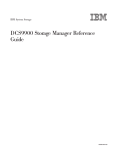
OPERATION OF BATTERY BACK-UP
WARNING!
D1, D2
R1, R2
R
THE BATTERY SHOULD BE LOCATED IN A WELL VENTILATED AREA TO SAFELY DISSIPATE HYDROGEN GAS
PRODUCED DURING THE CHARGING PROCESS.
SCHOTTKY DIODE: 30V, 180A
POWER RESISTOR: 0.78 OHM, 35W
STATIC LOAD RESISTOR: 120 OHM, 5W
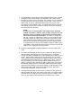
FUGURE A.
Please refer to the schematic at fig. A above.
Regulated output voltage of 14.2VDC +/ - 1% from the modules ( measured at screw
terminals S5 and S6 (Fig.1) is fed to the positive and negative DC bus bars and from
there to the output terminals LOAD+ and LOAD- through the isolating Schottky Diode D1. Although the output voltage at the module terminals S5 and S6 ( Fig.1) or at
the common DC bus bar (before the Schottky Diode D1) is tightly regulated at the
preset value of 14.2VDC +/ - 1%, the voltage at the output terminals Load + and
Load - will vary slightly due to the forward voltage drop of the isolating Schottky Diode D1 and the drop along the DC bus bar and wiring. The voltage at the output
terminals LOAD + and LOAD – will be as follows :
At no external load
At 10 A load
At loads > 10A
Approx. 14V
Approx. 13.8V
Approx. 13.8V minus 5mV per Amp above 10A
When there is a requirement of un-interrupted D.C. power to the load, an external
battery may be connected at the terminals Battery + and Battery –. When the input
A.C. power is available, the load current is supplied by the power supply through
isolating Schottky Diode D1. At the same time, the battery is charged through resistors R1 & R2. (These resistors will limit the maximum charging current to about 8
Amperes.)
7.
If the input A.C. power is interrupted, the external battery feeds the load instantaneously through the Schottky Diode D2 (D2 will by-pass the resistors R1 & R2). Voltage
available to the load will be approximately 0.4V lower than the battery voltage due to
forward voltage drop across D2.
Availability of AC power is signaled for remote monitoring through an opto-coupled
signal through the D-Sub connector (see page 5 under “Remote monitoring & Signaling”). This signal may also be used to indicate that the load is being powered by battery (In case external battery is used for battery back-up).
When the input AC power returns, the battery will be isolated and the load current will
once again be supplied by the power supply. The discharged battery will recharge
through R1& R2 (R1&R2 are in parallel offering a net resistance of 0.39 Ohm).
NOTE: The value of charge limiting resistors is based on a typical 100AH deep cycle
marine battery. If a different type of battery is used, the value of the resistor should
be adjusted to meet associated charging requirements.
OUTPUT VOLTAGE ADJUSTMENT
NOTE : The voltages indicated are at no load and are measured at any of the module
output pads under S5 and S6 or at the DC bus before the Schottky Diode D1.
Parallel Operation Under Forced Current Share Control
The output voltage of each module measured at the module output pads under
S-5 and S-6 (See Fig.1) is factory pre-set at 14.2 V. A precision multi turn potentiometer VR1 is provided for fine adjustment of the output voltage of the module
(The adjustment range is 13.8 V to 14.6 V ).
For the forced current share control to work properly, it is important that the output
voltage of each module connected in parallel is exactly the same. When 2 or more
modules are operating in parallel under forced current share control and if the output
voltage of any module is below 14.2 V, it’s current share control circuitry will not
function properly and it’s LED will start flashing. The LEDs of the other modules
which are putting out 14.2 V will remain continuously lighted and the output voltage of
the common DC bus (before the Schottky Diode D1) will be 14.2 V.
If the output voltage of any module is higher than 14.2 V, it’s LED will remain continuously lighted but the LEDs of all the other modules will flash randomly. The output
voltage of the common DC bus (before the Schottky Diodes D1) will read the higher
voltage of this module.
Adjusting the output voltage of the modules at no load
NOTE : The output voltage is adjusted by multi turn potentiometer VR1 ( Fig.1). As the
adjustment is very fine, multiple turns will be required even for small voltage change.
Turn clockwise for decreasing and anti clockwise for increasing . The adjustment range
is 13.8V to 14.6V
As explained under OPERATION OF BATTERY BACK UP on page 7, although the
output voltage at the module terminals S5 and S6 ( Fig.1) or at the common DC bus
(before the Schottky Diode D1) is tightly regulated at the preset value of 14.2 V +/1%, the voltage at the output terminals Load + and Load - will vary between 14 V at
no load to 13.35 V at full load of 100 A due to the forward voltage drop of the isolating Schottky Diode D1 and the drop along the DC bus and wiring.
8.
The output voltage of the paralleled modules or the common DC bus (before the Schottky Diodes D1) can be adjusted between 13.8 V and 14.6 V by adjusting the voltage of each module
individually as per the following procedure ( This procedure is explained for SEC-100BRM
which has 5 modules ). The voltage at the output terminals LOAD + and LOAD – will be as
follows :
At no external load
At 10A load
At loads > 10A
Module voltage minus 0.2V
Module voltage minus 0.4V
Module voltage minus 0.4V minus 5mV per Amp above 10A
Procedure
•
•
•
•
•
•
•
•
•
Switch off the unit and unplug the power cord.
The output voltage of each individual power supply module (PSM) is adjusted one by one
starting from the left most module – PSM 1 and progressing to the right most module –
PSM No. 5 ( for SEC-100BRM ). AC input is connected only to the module being adjusted. AC input to the remaining modules is disconnected
Remove the AC input connections ( female quick connect terminals connected to the L and
N male tab terminals on the modules – Fig. 1 ) from PSM Nos. 2, 3, 4 and 5. Temporarily
insulate these female quick connect terminals with insulating tape for safety. Now, only
PSM No. 1 can be energized.
Switch on the power supply. Only PSM No. 1 will operate. Adjust the output voltage of
this module to the desired value with the help of potentiometer VR1 (Fig.1) Measure the
voltage at the screw terminals S5 and S6 (Fig.1)
Switch off the power supply. Remove the AC input connection from PSM No. 1. Temporarily insulate these terminals with insulation tape. Remove temporary insulation from the AC
connectors for PSM 2 and connect them to PSM 2. Now only PSM 2 can energize.
Switch on the power supply. Only PSM No. 2 will operate. Adjust the output voltage of
this module to the desired value with the help of potentiometer VR1 (Fig.1). Measure the
voltage at the screw terminals S5 and S6 (Fig.1)
Continue to adjust the voltage of the remaining Module Nos. 3, 4 and 5 individually as
explained above making sure that the AC power is connected to only the module being
adjusted.
After all the modules have been adjusted to the same output voltage, connect the AC input
back to all the five modules.
Power on the unit and check that all the 5 “PSM Status” LEDs are lighted. This will confirm that the voltage adjustment has been completed successfully.
NOTE: As explained under Design & Principle of Operation on page 3, it is likely that the
minimum internal preload current for the new value of the output voltage may not be
sufficient to provide adequate feedback signal strength resulting in shut down of one or
more PSM(s) when no external load is present (The associated PSM Status LED will flash
and also, the associated signal for remote indication will oscillate between High and
Low). In such a case, apply an external load to increase the feed back signal strength. If
there is no other defect, the PSM(s) that were shut down will also operate normally.
INSTALLATION AND REMOVAL OF POWER SUPPLY MODULES
NOTE:
INSTALLATION AND REMOVAL OF POWER SUPPLY MODULES
SHOULD BE PERFORMED ONLY BY QUALIFIED PERSONNEL
CAUTION!
Before removing a defective module or installing a new one, switch off the 120 V , 60 Hz input
power and unplug the power cord from the mains outlet.
NOTE:
Please refer to the layout diagram of the module at Figure. 1 located on page 17.
9.
UPGRADING TO HIGHER CAPACITY – INSTALLING ADDITIONAL MODULE(S)
Additional optional module(s) (Model No. SEC-2012MPSB) can be added to upgrade the output
current capacity of SEC-40BRM / SEC-60BRM / SEC-80BRM by steps of 20A to a maximum of
100A. For example, an SEC-40BRM (40 A, with 2 modules) can be upgraded to SEC-60BRM (60A)
by adding 1 more module or to SEC-80BRM (80A) by adding 2 more modules or to SEC-100BRM
(100 A) by adding 3 more modules.
The optional module SEC-2012MPSB comes with an LED and LED holder. It’s output voltage is
pre-set at 14.2 Volts
The procedure to install additional module(s) is as follows :
1.
Remove the top cover plate by unscrewing the 10 screws
2.
Each module sits on 6 stand-offs under the holes S1 to S6 (Fig.1). Additional module(s) are to be installed in
the vacant space(s) adjacent to the right of the existing module. Remove the screws from the 6 stand-offs
for the adjacent vacant space for the module.
3.
Place the module on the stand-offs with the L an N terminals (Fig.1) towards the front panel. Align the holes
and fix the module with the 6 screws. WARNING! Please ensure that screws S5 and S6 are very tight as
the pads under these two screws connect the output of the module(s) to the DC bus bar underneath.
A loose connection under these screws will result in sparking , overheating and consequent damage
to the module
4.
Each module has independent AC power input wires. Locate unused pair of AC input wires. (Black and
white with insulated female quick connect terminals). The black wire is required to be connected to the male
tab terminal marked L (Fig.1) and white wire is required to be connected to the male tab terminal marked N
(Fig.1). DO NOT CONNECT THESE WIRES TILL STEP 8 BELOW.
5.
Terminal marked LED2 (Fig.1) is used for the front panel LED under “PSM Status (1 to 5)” and terminal
marked LED1 (Fig.1) is used for remote indication through the D-Sub connector. The PSM status output
signal from connector LED1 is fed to the associated opto-coupler on the small opto-coupler PCB (Printed
Circuit Board) & from there it is fed to the D-Sub connector. Connection to the opto-coupler PCB and onward to the D-Sub connector for remote indication is made using color coded pair of wires for each of the 5
modules (Please see the colour code for PSM 1 to 5 under REMOTE MONITORING AND INDICATION on
Page 5). An LED holder and a green LED with wire and female quick connect terminal are provided with the
new module for connecting to the front panel. The vacant hole(s) for the front panel LEDs are closed with
plastic plug(s). Remove the plastic plug from the vacant hole for the LED under the existing bottom most
LED. Insert the LED holder in this hole from the outside. Insert the green LED from the inside and push it till
it locks. Connect the female quick connect terminal of the LED to the male quick connect terminal marked
LED2 (Fig.1). If remote indication is also required, then connect the female quick connect terminal of the
corresponding colour coded wire for the remote indication connection to the male quick connect terminal
marked LED1 (Fig.1)
6.
All the connected modules operate under forced current share control through a daisy chained SHARE BUS
formed by interconnecting each module through the male quick connect terminal marked JUMP1 (Fig.1 &
2). A wire with 5 female quick connect terminals is provided for the above connection. Locate the unused
female quick connect terminal(s) of this wire and connect it to the male quick connect terminal marked
JUMP1 (Fig.1)
7.
Use cable ties to secure all loose wiring
8.
As explained under “OUTPUT VOLTAGE ADJUSTMENT” on pages 8 and 9, the output voltage at the individual modules (Measured at points S5 & S6 of the module as shown at Fig. 1 on page 17) is required to be
set exactly at the same voltage for proper current share control. Each module is factory preset at a voltage
of 14.2V with the help of potentiometer VR1. Although the optional module SEC-2012MPSB is factory preset
at 14.2V, it may differ slightly due to tolerance. It is, therefore, necessary to ensure that the voltage of all the
individual paralleled modules {the existing modules and the additional optional module(s)} is set exactly at
14.2V. For this, follow instructions given under “Procedure” on page 9.
9.
Replace the top cover. Power on the unit and confirm that the “PSM Status” LEDs of all the installed modules are lighted.
10.
REMOVING A DEFECTIVE MODULE
1. Remove the top cover plate by unscrewing the 10 screws.
2. Locate the defective module. Remove the 6 screws from S1 to S6.
3.
Remove the input power supply wires from terminals “L” and “N”. Insulate the
wire terminals with insulating tape
4. Remove connectors from terminals “LED 1 & LED 2” .
5.
Remove the “SHARE BUS” wire female socket connector from the terminal
“JUMP1”. If the defective module is not being replaced immediately and if the
unit is required to be operated without this defective module.
IT IS MANDATORY TO SHORT THE TWO FEMALE SOCKETS ON
THIS UNUSED FEMALE CONNECTOR WITH A SHORTING LINK.
(SEE FIG. 3 ) THIS WILL ENSURE THAT THERE IS NO BREAK IN
THE “SHARE BUS” DAISY CHAIN AND THAT ALL THE “JUMP1”
TERMINALS ARE INTERCONNECTED.
6. The module can now be removed.
TROUBLE SHOOTING
POWER ON/OFF SWITCH DOES NOT LIGHT WHEN SWITCHED ON
Check that power is available in the AC outlet
Check that the power cord plug is properly plugged in
·
·
BREAKER TRIPS
The breaker has tripped due to abnormal condition. Call technical support
·
“FAN FAILURE” LED LIGHTS UP AND BUZZER IS SOUNDED
·
One or both of the fans have stopped
Forced cooling has failed due to defect in the cooling fan(s). Switch off the
unit immediately. Fan(s) needs to be replaced.
DO NOT USE THE UNIT TILL THE DEFECT IS RECTIFIED. IT IS PROHIBITED TO USE THE UNIT WITHOUT FORCED COOLING. Call technical support.
·
If both the fans are running, the small fan status monitoring PCB may be
defective. Call technical support.
11.
“ PSM STATUS ” LED(S) DOES NOT LIGHT UP
·
The associated module has become defective. The unit will still operate
normally as the remaining working modules will share a higher load. The
unit will go into current limit and the output voltage will drop if the load
drawn is more than the combined maximum rated output of the remaining
modules. Reduce the load so that the maximum load drawn is less than the
combined maximum rated output of the working modules.
Remove the defective module and replace with a new module.
OUTPUT VOLTAGE DROPS ON LOAD
·
The unit has gone into current limit as the load being drawn is more than
the combined maximum rating of the working modules. This may also result
if one or more modules has failed . Check that all the modules are
operating properly. If a module has failed, its green LED would extinguish
or flash. Reduce the load drawn to a value less than the combined
maximum rated output of the working modules. If the voltage does not rise
to the rated voltage of 13.65 V to 13.35 V, then switch off all the loads. If
the voltage in this condition is also low, switch off the unit and contact
technical support
ONE OR MORE “PSM STATUS” LED(S) FLASHES
·
The output voltage of the individual modules is not the same or the forced
shared control circuitry of the module(s) is defective. Adjust the voltages of
the modules to 14.2V as explained on page 8.
If the problem still exists, contact technical support.
·
If the one or more PSM status LED(s) flash when no external load is connected, it may mean that the internal pre-load current is not sufficient to
provide adequate feedback signal for the current share control circuitry.
Apply external load. If the flashing stops, the associated PSM(s) are normal. If flashing continues even after applying an external load, contact technical support.
12.
LIMITING ELECTROMAGNETIC INTERFERENCE (EMI)
1.
Switched mode power supplies ( SMPS ) employ high frequency switching
and thus, are a source of radio interference, a recipient of radio interference
and a conduit of radio interference. ( Older linear type transformer based
power supplies do not employ high frequency switching voltages and will be
quieter as compared to switching type of supplies ).
2.
The primary emission sources originate in the switching devices due to their
fast switching current transitions: harmonics of the switching frequency and
broadband noise created by under-damped oscillations in the switching circuit. The secondary source is from the bridge rectifier, both rectifier noise
and diode recovery. The AC input rectifier / capacitor in the front end of the
switching power supplies ( excepting those with power factor correction ) are
notorious for generating power supply harmonics due to the non linear input
current waveform. The noise is both conducted and radiated through the
input power cord and the DC output wiring to the radio. Filters are used to
limit the noise to acceptable level.
3.
Switching power supplies are also recipients of radio interference. The normal operation of the power supply can be disturbed due to RF noise getting
coupled into the power supply. Thus, the power supply may generate excessive RF noise and lose output voltage regulation due to excessive transmitter
energy being coupled through the AC / DC lines to the power supply’s regulator feedback path. This may be due to antenna being too close or due to
the antenna or feed system not radiating properly. First check the antenna
system SWR. Then, if necessary, relocate either the antenna or the power
supply farther apart.
4.
The receiver may “hear” the power supply. A slowly moving, slightly buzzing
carrier heard in the receiver may be caused by the antenna being too close.
As with the transmitter related noise pick up, a loose coaxial connector or a
broken or a missing ground may aggravate this problem. Normally these
noises will be below the background or “band” noise. Increase the separation
between the power supply and the receiving antenna. Use an outdoor antenna. This will reduce the amount of signal picked up from the power supply
and also increase the amount of the desired signal.
13.
5.
The conducted RF noise from these power supplies is limited to the maximum
allowable levels by internal filtration. The filtered RF noise currents are bypassed to the chassis of the power supply. The chassis is, in turn connected to
the earth ground pin of the AC input power cord (for Class 1 units). Thus, the
filtered noise currents are intentionally leaked to the earth ground. This is
termed as the “Earth Leakage Current”. For safety against electric shock, this
earth leakage current is also required to be limited. It will be seen that these
two requirements are conflicting.
NOTE:
In some cases, to prevent electric shock hazard due to abnormal
leakage current (like in marinas, spas, hot tubs, wet spaces etc.), the
AC outlet circuits / receptacles in these areas are served through a
GFCI ( Ground Fault Circuit Interrupter ). This GFCI is normally set to
trip when it senses an earth leakage current > 5 mA. A single GFCI may
be serving multiple AC outlet circuits / receptacles and therefore, will be
sensing the sum of all the leakage currents of the devices connected to
these. As the switching power supplies have intentional leakage current
as explained above, it may trip a GFCI feeding multiple AC outlet circuits /
receptacles. In such cases, disconnect devices connected to the other AC
outlet circuits / receptacles served by this GFCI.
6.
Following additional guidelines may be followed to reduce the effects of RF
noise:
a.
Use additional appropriate AC radio frequency interference (RFI) power line
filter immediately before the AC input of the power supply. For example,
125VAC, 30A filter “F1700DD30” from Curtis Industries (www.curtisind.com) or
similar. Filtered, ferrite coated cord set (www.emceupen.com ) is another
choice. These cord sets, with integral line interference filters, reduce common
and differential mode interferences over a wide frequency range. Because
they are shielded, they are also effective against radiated interferences. In
addition to the built-in filter networks, the cable conductors are coated with an
RF absorbing ferrite compound. This provides additional attenuation at high
frequencies that is lacking in most regular LC filters. The RF absorption of the
ferrite-coated cable avoids resonance’s at high frequencies, reducing the
conducted and radiated RF noises even further
b.
Use additional appropriate DC radio frequency interference (RFI) power line
filter immediately after the dc output of the power supply. For example, 80VDC,
100A filter from “DC” series by Corcom (www.corcom.com) or 80VDC, 100A
filter from “FD” series by Curtis Industries (www.curtisind.com) or similar.
14.
c.
Twist the positive and negative wires from the output of the power supply to
the radio
d.
The DC side positive and negative outputs of these power supplies are isolated from the chassis. As explained at paragraph 5 above, the noise currents
are filtered to the chassis ground and the chassis ground is connected to the
earth ground through the earth ground pin of the AC power outlet receptacle.
Avoid connecting (referencing) the DC negative output terminal of the power
supply to the earth ground.
e.
Connect a 1/4” wave length of wire on the negative terminal of the power supply. Connect one end of the wire to the negative terminal and leave the other
end free. The wave length corresponds to the wave length of the interfering
frequency. (May not be practical for long wave lengths)
[ Formula: Wave length (Meters) = 300 / frequency in MHz
15.
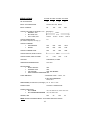
SPECIFICATIONS
SEC-40BRM SEC-60BRM
SEC-80BRM
NO. OF MODULES
2
INPUT VOLTAGE RANGE
105 TO 125 V AC, 60 HZ
INPUT CURRENT
8A
3
SEC-100BRM
4
12A
16A
5
20A
OUTPUT VOLTAGE (At terminals L+ & L- , See page 7)
•
NOMINAL, VDC
13.8 V
•
NO LOAD, VDC
14 V
•
FULL LOAD, VDC
13.65 V 13.55 V 13.45 V
OUTPUT REGULATION
(At module output S5, S6—Fig. 1)
13.35 V
1%
OUTPUT CURRENT
•
CONTINUOUS
•
SURGE
40A
46A
60A
69A
80A
92A
100 A
115A
OUTPUT CURRENT LIMIT
48A
72A
96A
120A
OUTPUT RIPPLE, PEAK TO PEAK
150mV
OUTPUT NOISE, PEAK TO PEAK
1V
COOLING
FORCED AIR, 2 FANS
OPERATING TEMPERATURE
0 TO 40 C
PROTECTIONS
•
SHORT CIRCUIT
•
CURRENT LIMIT
•
FAN FAILURE
•
INPUT SURGE SUPRESSION
YES
YES
LED AND BUZZER
YES
FUSE / BREAKER
0.9V
0.8V
0.7V
● MODULE FUSE – 250 V, 4 A
● UNIT HAS A BREAKER
250 V, 20 A
DIMENSIONS(19” Rack Mount, 2U height) 19” X 15.9” X 3.6”
POWER CORD
12 AWG / 3 CONDUCTOR
POWER CORD PLUG
•
SEC-100BRM
•
SEC-40BRM/60BRM/80BRM
125V, 30A, NEMA L5-30P, TWIST LOCK TYPE
WEIGHT, LBS
20.5
125V, 20A, NEMA 5-20P
22
23.5
NOTE: SPECIFICATIONS SUBJECT TO CHANGE WITHOUT NOTICE
16.
25
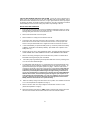
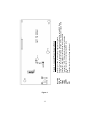
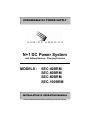
Figure 1.
17.
S1 to S4
S5 & S6
L&N
LED 1
LED 2
JUMP 1
F1
VR1
Holes for 4 screws to fasten the module to the chassis
Holes for 2 screw to connect to the Positive and Negative output BUS Bars
L ( line ) and N ( neutral ) terminals for 120V, 60 Hz input power supply wires
Terminal for “ON“ status for opto-isolated remote indication
Terminal for “LED“ PSM status for front panel indication
Jumper terminal for connecting share BUS wire
Fuse
Potentiometer for output voltage adjustment
Figure 1 - Layout of Power Supply Module
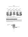
Figure 2.
“ Daisy Chaining “ of “Share BUS “ jumpers ( Jump 1 )
PSM 1
PSM 2
PSM 3
PSM 4
PSM 5
1
1
1
1
1
2
2
2
2
2
PCB ( Printed Circuit Board )
Jump 1
Jump 1
Jump 1
Jump 1
Jump 1
1. Female socket terminal of the daisy chain.
2. Male 2 pin terminal marked “Jump 1“ on the Power Supply Module.
CONTINUITY OF “ DAISY CHAIN “ CONNECTIONS
Removing any end module (example PSM1/PSM5 in Fig. 2 above) does not break
the daisy chain. However, if any of the sandwiched modules (example PSM 2,3,4) is
removed, the daisy chain is broken. In this case, the unused female socket for the
missing sandwiched module(s) should be shorted by inserting a shorting link to prevent a break in the daisy chain (Fig.3)
Unused female
socket.
Shorting Link
Figure 3.
18.
2 YEAR Limited Warranty
This product manufactured by Samlex America, Inc. (the “Warrantor”) is warranted to be free
from defects in workmanship and materials under normal use and service. This warranty is in
effect for 2 years from the date of purchase by the user (the “Purchaser”)
If the defective product is within the warranty period, the Purchaser should contact the place of
purchase to obtain a Return Authorization Number.
The defective part or unit should be returned at the Purchaser’s expense to the authorized
location. A written statement describing the nature of the defect, the date of purchase, the place
of purchase, and the Purchaser’s name, address and telephone number should also be included.
If upon the Warrantor’s examination, the defect proves to be the result of defective material or
workmanship, the equipment will be repaired or replaced at the Warrantor’s option without
charge, and returned to the Purchaser at the Warrantor’s expense if within the warranty period.
No refund of the purchase price will be granted to the Purchaser, unless the Warrantor is unable to remedy the defect after having a reasonable number of opportunities to do so.
Warranty service shall be performed only by the Warrantor. Any attempt to remedy the defect
by anyone other than the Warrantor shall render this warranty void.
There shall be no warranty for defects or damages caused by faulty installation or hook-up,
abuse or misuse of the equipment including exposure to excessive heat, salt or fresh water
spray, or water immersion.
No other express warranty is hereby given and there are no warranties which extend beyond
those described herein. This warranty is expressly in lieu of any other expressed or implied
warranties, including any implied warranty of merchantability, fitness for the ordinary purposes
for which such goods are used, or fitness for a particular purpose, or any other obligations on
the part of the Warrantor or its employees and representatives.
There shall be no responsibility or liability whatsoever on the part of the Warrantor or its employees and representatives for injury to any persons, or damage to person or persons, or damage to property, or loss of income or profit, or any other consequential or resulting damage
which may be claimed to have been incurred through the use or sale of the equipment, including any possible failure of malfunction of the equipment, or part thereof.
The Warrantor assumes no liability for incidental or consequential damages of any kind.
Samlex America Inc. (the “Warrantor”)
110-17 Fawcett Road
Coquitlam BC V3K6V2 Canada
(800) 561-5885
(604) 525-3836
19.
Attach copy of receipt here for your records:
Date purchased:
Purchased from:
Additional notes:
20.
Thank you for purchasing a Samlex power supply product !
Samlex America Inc.
110 –17 Fawcett Road
Coquitlam, B.C. V3K 6V2 Canada
SEC-40/60/80/100BRM _Nov2007