1
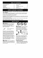
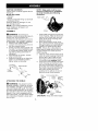
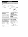
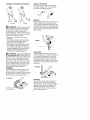
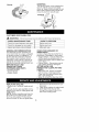
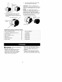
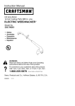
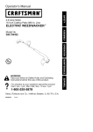
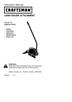
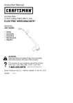
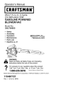
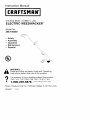
Instruction
Manual
I CRRFTSMRN°I
4.6 Amp Motor / 0.080 In. Line
ELECTRIC
WEEDWACKER
®
Model No.
358.745320
•
Safety
• Assembly
• Operation
• Maintenance
•
Espa6ol
®
Read
and follow all Safety Rules and Operating
WARNING:
Instructions
before first use of this product.
For
Call answers
7 am-7
•
Sears,
530165790
to your
questions
this product:
pm,
Mon-Sat;
Sun,about
10 am-7
pm
1-800-235-5878
Roebuck
1/25/05
(Hours
and Co., Hoffman
listed are Central
Estates,
Time)
IL 60179
U.S.A.
Warranty Statement
Safety Rules
2
2
Parts Available
Storage
Assembly
Operation
Maintenance
5
6
8
Troubleshooting
Service & Adjustments
8
Parts Ordering
FULL ONE YEAR WARRANTY
LINE TRIMMER
9
9
Table
10
Spanish
ON CRAFTSMAN
11
Back Cover
ELECTRIC
WEEDWACKER
®
If this Craftsman Electric Weedwacker _ Line Trimmer fails to perform properly
due to a defect in material or workmanship
within (1) one year from the date of
purchase, Sears will replace it free of charge.
This warranty
does not cover the nylon line.
WARRANTY SERVICE IS AVAILABLE BY RETURNING THE CRAFTSMAN ELECTRIC
WEEDWACKER
LINE TRIMMER TO THE NEAREST SEARS STORE OR SERVICE CENTER IN THE UNITED STATES.
This warranty gives you specific
which vary from state to state.
Sears, Roebuck
legal rights, and you may also have other rights
and Co., D/817WA,
Hoffman
4t_WARNING:
When using electric
gardening appliances, basic safety
precautions must always be followed
to reduce the risk of fire, electric
shock, and serious injury= Read and
follow all instructions=
j_
Estates,
IL 60179
_1_ WARNING:
Trimmer line throws
objects violently. You and others can
be blinded/injured.
Wear safety
glasses, boots, and leg protection.
Keep body parts clear of rotating line.
Safety Glasses or similar eye protection
ON
THE UNIT
SAFETY
INFORMATION
This power unit can be dangerous!
Operator is responsible for following
the warnings and instructions in this
manual and on the unit. Read entire
instruction manual before using unit!
Be thoroughly familiar with the controis and the proper use of the unit.
Restrict the use of this unit to persons
who read, understand, and follow unit
and manual warnings and instructions. Never allow children to operate
this unit. Close attention is necessary
when used near children.
Boots
Keep children, bystanders, and animals 50 feet (15 meters) away. If approached stop unit immediately.
If situations occur which are not covered in this manual, use care and
good judgement. If you need assistance, call 1-800-235-5878.
OPERATOR SAFETY
• Dress properly. Always wear safety
glasses or similar eye protection when
operating, or performing maintenance
on your unit. (Safety glasses are
,t%
all, DANGER:
Never use blades or
flailing devices. Unit is designed for line
trimmer use only. Use of any other accessories or attachments will increase
the risk of injury=
2
available.)
Always
wear
faceordust • To reduce risk of electrical shock,
mask
ifoperation
isdusty.
Always
use extension cords specifically
wear
heavy,
longpants,
longsleeves, marked as suitable for outdoor apboots,
andgloves.
Donotgobarefoot pliances having electrical rating not
orwear
sandals.
less than the rating of unit. Cord
• Secure
hairabove
shoulder
length. must be marked with suffix "W-A" (in
Secure
orremove
loose
clothing
Canada "W"). Make sure your extenandjewelry
orclothing
withloosely
sion cord is in good condition. Inhanging
ties,straps,
tassels,
etc.
spect extension cord before use and
Theycanbecaught
inmoving
parts. replace if damaged. Do not use a
• Being
fullycovered
alsohelps
prodamaged cord. Cord insulation
must be intact with no cracks or detectyoufromdebris
andpieces
of
toxicplants
thrown
byspinning
line.
terioration. Plug connectors must be
• StayAlert.
Donotoperate
unitwhen undamaged. An undersized extenyouaretired,ill,upset
orunderinsion cord will cause a drop in line
fluence
ofalcohol,
drugs,
ormedica- voltage resulting in loss of power
tion.Watch
whatyouaredoing;
use
and overheating. If in doubt, use the
common
sense.
next heavier gauge. The lower the
• Avoid
unintentional
starting
ofthe
gauge number, the heavier the cord
unit.Never
carryunitwithyourfinger (see SELECT AN EXTENSION CORD
ontheswitch.
Besuretheswitch
is
in the OPERATION section).
intheOFF
position
andnever
touch • Do not use multiple cords.
theswitch
whenconnecting
exten- • Do not abuse cord. Never carry the
sioncord.
unit by the extension cord or yank
ELECTRICAL
SAFETY
,_ WARNING:
Avoid a dangerous
environment.
To reduce the risk of
electrical shock, do not use in rain, in
damp or wet locations, or around
swimming pools, hot tubs, etc. Do not
expose to snow, rain, or water to avoid
the possibility of electrical shock.
• Use a voltage supply as shown on
unit.
• Avoid dangerous situations. Do not
use in the presence of flammable
liquids or gases to avoid creating a
fire or explosion and/or causing
damage to unit.
• To reduce the risk of electrical
shock, this equipment has a polarized plug (one blade is wider than
the other) and will require the use of
a polarized extension cord. The appliance plug will fit into a polarized
extension cord only one way. If the
plug does not fit fully into the extension cord, reverse the plug. If the
plug still does not fit, obtain a correct
polarized extension cord. A polarized extension cord will require the
use of a polarized wall outlet. This
plug will fit into the polarized wall
outlet only one way. If plug does not
fit fully into the wall outlet, reverse
the plug. If it still does not fit, contact
a qualified electrician to install the
proper wall outlet. Do not change
the equipment plug, extension cord
receptacle, or extension cord plug in
any way.
extension cord to disconnect unit.
• Tie cord to cord retainer and connect to recessed plug as shown in
this manual to prevent damage to
unit and/or extension cord and to reduce the possibility of the extension
cord disconnecting from the unit during operation. See ATTACH THE EXTENSION CORD TO YOUR TRIMMER
in the OPERATION section.
• Do not use the unit if the switch does
not turn the unit on and off properly.
Repairs to the switch must be made
by your Sears Service Center.
• Keep the extension cord clear of operator and obstacles at all times. Do
not expose cords to heat, oil, water,
or sharp edges.
• To avoid the possibility of electric
shock, avoid body contact with any
grounded conductor, such as metal
fences or pipes.
• Ground Fault Circuit Interrupter
(GFCI) protection should be provided on circuit or outlet to be used.
Receptacles are available having
built-in GFCI protection and may be
used for this measure of safety.
UNIT SAFETY
• Inspect unit before use. Replace
damaged parts. Make sure all handles, guards, and fasteners are in
place and securely fastened. Parts
that are damaged must be repaired
or replaced by a Sears Service Center These include head parts that
are cracked, or chipped, guards,
and any other part that is damaged.
• Donotrepair
unityourself.
• UseonlyCraftsman_
brand
trimmer
line(seeSERVICE
AND
ADJUSTMENTS).
Never
usewire,rope,
string,
etc.
• Usespecified
trimmer
spool.Make
surespool
isproperly
installed
and
allparts
aresecurely
fastened.
• UseonlyCraftsman
replacement
parts
a
nd
accessories
asrecommended.
CUTTING
SAFETY
• Inspect area to be cut. Remove objects (rocks, broken glass, nails,
wire, string, etc.) which can be
thrown or become entangled in cutting head.
• Do not overreach or stand on unstable support. Keep firm footing and
balance.
• Keep the cutting head below waist
level. Do not raise handles above
your waist. Cutting head can come
dangerously close to your body.
• Keep away from cutting head and
spinning line.
• Use unit properly. Use only for trimming, edging, scalping, and mowing. Do not force unit. It will do the
job better and with less risk of injury
at the rate for which it was designed.
• Use only in daylight or in good artificial light.
MAINTENANCE
SAFETY
WARNING:
Disconnect
unit from
the power supply before performing
maintenance,
or when changing trimmer line.
• Maintain unit according to recommended procedures. Keep cutting
line at proper length. Follow instructions for changing trimmer line.
• Have all service and maintenance
not explained in this manual performed by a Sears Service Center to
avoid creating a hazard.
• Never douse or squirt the unit with
water or any other liquid. Clean unit
and labels with a damp sponge.
Keep handles dry, clean, and free
from oil and grease.
• Keep the air vents clean and free of
debris to avoid overheating the motor. Clean after each use.
TRANSPORTING
AND STORAGE
• Stop the unit and disconnect the
power source when not in use.
• Carry the unit with motor stopped.
• Store the unit so the line limiter
blade (on underside of shield) cannot cause injury.
• Store unit indoors in a high, dry
place out of the reach of children.
Store unit unplugged.
• Do not hang unit so that the trigger
switch is depressed.
DOUBLE INSULATION
CONSTRUCTION
This unit is double insulated to help
protect against electric shock. Double
insulation construction consists of two
separate "layers" of electrical insulation instead of grounding.
Tools built with this insulation system
are not intended to be grounded. No
grounding means is provided on this
unit, nor should a means of grounding
be added to this unit. As a result, the
extension cord used with your unit can
be plugged into any standard 120 volt
electrical outlet.
Safety precautions must be observed
when operating any electrical tool.
The double insulation system only
provides added protection against injury resulting from an internal electrical
insulation failure.
_, WARNING:
All electrical repairs
to this unit, including housing, switch,
motor, etc., must be diagnosed and
repaired by qualified service personnel. Replacement parts for a double
insulated appliance must be recommended by the manufacturer. A
double insulated appliance is marked
with the words "double insulation" or
"double insulated". The symbol
(square within a square) [] may also
be marked on the appliance. Failure to
have the unit repaired by qualified service personnel can cause the double
insulation construction to become ineffective and result in serious injury.
SAVE THESE INSTRUCTIONS
CARTON
CONTENTS
Check carton contents against the following list.
Model 358.745320
• Trimmer
• Shield
• Assist handle with wing nut and bolt
• Container of line
Examine parts for damage. Do not
use damaged parts.
NOTE: If you need assistance or find
parts missing or damaged, call
1-800-235-5878.
NOTE: Edge guide must be positioned on shield prior to installation
on motor housing (see following
illustration).
Edge
Guide
L_
Shield
ASSEMBLY
_WARNING:
sembled, review
ensure your unit
sembled and all
If received asall assembly steps to
is properly asfasteners are secure.
ATTACHING THE ASSIST HANDLE
1. Place unit on a flat surface.
2. Loosen and remove wing nut and
bolt from assist handle.
3. Firmly push the assist handle over
the tube. To make installation easier, tilt handle toward trigger housing while pushing down (see illustration).
4. Reinstall bolt in handle. Thread
wing nut onto bolt.
5. Adjust the handle up or down the
tube to a comfortable position;
tighten wing nut securely.
Trigger
Housing
"X_, .i '/'_
--\x,_:,_';_7 _--'_
1.
Hold shield at angle to the trimmer
motor housing. Align the front locking tab of the shield with the front
notch of the motor housing (see
illustration below).
2. Move shield toward motor housing, ensuring trimmer head passes
through opening in shield without
catching on shield locking tabs.
NOTE: Ensure the cutting head remains free to rotate and the line is not
caught between the shield and the
motor housing.
3. Tilt front of the shield towards front
notch of motor housing. Push front
locking tab of the shield into the
front notch of the motor housing.
An audible snap must be heard.
4. Push back of the shield toward the
motor housing as illustrated until
the rear locking tabs snap securely into the rear notches. Make sure
the shield is securely attached to
the motor housing and is assembled to the unit as shown on
the front cover of this manual.
Rear
Locking
Tabs
ATTACHING
_
Front Locking Tab
Front
Trimmer
Notch
Motor
Housing
THE SHIELD
WARNING:
The shield must be
properly installed. If shield is not properly installed, damage to unit (including motor failure) will result. The shield
provides partial protection to the operator and others from the risk of thrown
objects. Your unit is equipped with a
line limiter blade. The line limiter blade
(on underside of shield) is sharp and
can cut you.
nmmer
Head
CAUTION:
Sharp
line
Notches
limiter
blade
KNOW YOUR TRIMMER
READ THIS INSTRUCTION MANUAL AND SAFETY RULES BEFORE OPERATING YOUR
UNIT. Compare the illustrations with your unit to familiarize yourself with the location of the various controls and adjustments. Save this manual for future reference.
Trigger Switch
Assist Handle
? ,jr
......
Twist and Edge Button
Cord '/
Retainer
Motor Housing
z
Recessed
Edge Guide
Plug
Air Vents
",_
Debris Shield
/
_'_[
Trimmer
Head
Line Limiter Blade
RECESSED PLUG
The RECESSED PLUG is used to connect the unit to an extension cord.
CORD RETAINER
The CORD RETAINER is used to secure the extension cord to the unit.
TRIGGER SWITCH
The TRIGGER SWITCH is used to turn
on the unit. Squeeze the trigger switch
to operate the unit. Release to stop.
LINE LIMITER BLADE
The LINE LIMITER BLADE cuts the cutting line to the proper cutting length.
OPERATING
INSTRUCTIONS
Use only a voltage supply as specified
on your unit.
SELECT
AN EXTENSION
Extension
CORD
Cord Gauge Chart
Length of Cord
Gauge
25 Ft. (7.5 m)
50 Ft. (15 m)
100 Ft. (30 m)
18 Gauge
16 Gauge
16 Gauge
Extension cords are available for this
unit at Sears.
Extension Cord
(16 Gauge) ............
71-85708
ASSIST HANDLE
The ASSIST HANDLE is used to help
hold and guide the unit.
TRIMMER HEAD
The TRIMMER HEAD holds the cutting
line and rotates during operation.
TWIST AND EDGE BUTTON
The TWIST AND EDGE BUTTON is used
to twist the lower portion of the unit
into an edging position.
EDGE GUIDE
The EDGE GUIDE protects the unit
from contacting the ground during
edging.
ATTACH THE EXTENSION
CORD TO YOUR TRIMMER
Loop your extension cord through the
handle and around the hook as
shown. Insure the plug and cord are
firmly and fully engaged.
CAUTION:
Failure to use cord retainer could result in damage to the unit,
extension cord, or both.
Cord Retainer
Extension
Cord
CORRECT
OPERATING
POSITION
EDGING
POSITION
You can press this button and twist
the lower portion 180" counterclockwise into an edging position.
EDGING
While edging allow tile tip of the line to
make contact. Do not force the line.
The edge guard helps protect the unit
and keeps the unit from contacting the
ground. Take extra caution while edging as objects can be thrown from the
trimmer line.
d
Trimming
Edging
A
m_, WARNING:
Always wear eye protection. Never lean over the trimmer
head. Rocks or debris can ricochet or
be thrown into eyes and face and
cause blindness or other serious injury.
When operating unit, stand as shown
and check for the following:
• Wear eye protection and heavy
clothing.
• Hold trigger handle with right hand
and assist handle with left hand.
• Keep unit below waist level.
• Cut only from your right to your left to
ensure debris is thrown away from
you. Without bending over, keep line
near and parallel to the ground (perpendicular when edging) and not
crowded into material being cut.
SCALPING
The scalping technique removes unwanted vegetation. Hold the bottom of
the trimmer head about 3 inches (8
cm) above the ground and at an angle. Allow the tip of the line to strike
the ground around trees, posts, monuments, etc. This technique increases
line wear.
_ WARNING:
Use only 0.080 inch
(2 mm) diameter line. Other sizes of
line will result in improper cutting head
function or can cause serious injury.
Do not use other materials such as
wire, string, rope, etc. Wire can break
off during cutting and become a dangerous missile that can cause serious
injury. See page 2 for warning concerning other cutting devices.
TRIMMING
Hold tile bottom of tile trimmer head
about 3 inches (8 cm) above the
ground and at an angle. Allow only the
tip of the line to make contact. Do not
force trimmer line into work area.
Trimming
_i_
/
S
Scalping
MOWING
Your trimmer is ideal for mowing in
places conventional lawn mowers
cannot reach. In the mowing position,
keep the line parallel to the ground.
Avoid pressing the head into the
ground as this can scalp the ground
and damage the tool.
4,
L
3 inches (8 cm)"_\_',_
above ground
7
SWEEPING
The fanning action of the rotating line
can be used for a quick and easy
clean up. Keep the line parallel to and
above the surfaces being swept and
move the tool from side to side.
Sweeping
CUSTOMER
RESPONSIBILITIES
WARNING:
Disconnect
power source before performing
CARE & MAINTENANCE
TASK
Check for loose fasteners
and parts
Check for damaged
Before each use
Before each use
or worn parts
After each use
Inspect and clean unit and labels
GENERAL RECOMMEN DATIONS
The warranty on this unit does not
cover items that have been subjected
to operator abuse or negligence. To
receive full value from the warranty,
the operator must maintain unit as
instructed in this manual. Various adjustments will need to be made periodically to properly maintain your unit.
BEFORE
EACH USE
CHECK FOR LOOSE
FASTENERS AND PARTS
• Housing Screws
• Assist Handle
• Debris Shield
REPLACING THE LINE
• Always use Craftsman replacement
line.
Only use the line size specified and designed for this unit for cutting grass and
small weeds.
NOTE: Before inserting new line into
the holes in the cutting head, locate
the three hole pattern. Follow directions as shown on the line glide plate.
maintenance.
WHEN TO PERFORM
CHECK FOR DAMAGED OR
WORN PARTS
Contact a Sears Service Center for replacement of damaged or worn parts.
• Trigger Switch - Ensure switch functions properly by pressing and releasing the trigger switch. Make sure
motor stops.
• Debris Shield - Discontinue use of
unit if debris shield is damaged.
AFTER
EACH USE
INSPECT AND CLEAN UNIT AND
LABELS
• After each use, inspect complete
unit for loose or damaged parts.
Clean the unit using a damp cloth
with a mild detergent.
• Wipe off unit with a clean dry cloth.
1.
2.
3.
Remove the old line from the cutting head.
Clean entire surface of cutting head=
Insert both ends of your line
through the proper holes in the
side of the cutting head=
5.
Positioning
Tunnel
4.
Line glide plate
Pull the line and make sure the
line is against the hub and extended full through the positioning
tunnels.
Line against the hub
Correctly installed line will be the
same length on both ends.
CAUTION:
If line is installed incorrectly, the cutting head will not function
properly and damage to the unit may
occur,
NOTE: Line glide plate must be
installed in cutting head before inserting new line. To reinstall line glide
plate (if needed), align arrow with center hole of three hole pattern on side
of cutting head as shown.
Center hole of three hole pattern
Line glide
Arrow
Positioning
Tunnel
Cutting head
USER REPLACEABLE
REPLACEMENT
SERVICE
Container of Replacement
Assist Handle
Bolt Carriage,
PARTS
PART
PART
Line
1/4-20
NUMBER
71-85907
530403805
530403886
Wing Nut
530016152
Shield Assembly
530404393
Edge Guide
530403845
A
WARNING:
Perform the following
steps after each use.
• Stop the unit and disconnect the
power source when not in use.
• Carry the unit with motor stopped.
• Store the unit so the line limiter
blade cannot cause injury.
• Store unit and extension cord indoors in a high, dry place out of the
reach of children. Store unit unplugged.
• Store unit with all guards in place.
Position unit so that any sharp object cannot accidentally cause injury.
TROUBLESHOOTING
TABLE
WARNING:
Always stop unit and disconnect from tile power source before
performing all of the recommended remedies below except remedies that require unit to be operating.
TROUBLE
CAUSE
REMEDY
Trimmer head
stops under a
load or does not
turn when switch
is pressed.
1. Crowdh_g line against
material being cut.
2. Electrical failure.
1. Allow tip of line to do the cutth_g.
Line breaks
while cutting,
1. Une improperly routed
in head.
2. Incorrect line size
3. Dirt build-up on unit.
3. Thrown circuit breaker.
4. Debris stopping head.
2. Contact Sears Service
cover).
3. Check breaker box.
4. Remove debris.
(see back
1. Check Ih_e routing.
2. Use only 0.080 inch (2 mm) dia. line.
3. Clean unit.
Line welds onto
cutting head.
1. Line size is incorrect.
2. Crowding line against
material being cut.
1. Use only 0.080 inch (2 mm) dia. line.
2. Allow tip of line to do the cutting.
Line usage is
excessive,
1. Line improperly routed
in head.
2. Line size is incorrect.
3. Crowding line against
material being cut.
4. Cutting head worn or
damaged,
1. Check Ih_e routing.
2. Use onIy 0.080 inch (2 mm) dia. Iine.
3. Allow tip of line to do the cutting.
4. Contact
cover).
10
Sears
Service
(see back