1
98648-000-60
Sartorius Industry
IB 16000 S,
IB 31000 P, IB 31.
Electronic Precision Scales
Installation and Operating Instructions
2
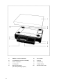
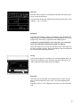
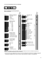
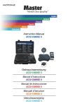
1
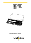
Platform cover for scale base
6
Tare control
2
Level indicator (only for IB 16000S)
7
CAL key
3
Power receptacle
8
ON/OFF key
4
Leveling foot
9
Weight display
5
Menu access switch
(for scale operating program)
10
Manufacturer’s label
Contents
Page
About the Product (Warranty)
Storage and Shipping Conditions
4
5
Equipment Supplied
6
Installations Instructions
Ambient Conditions
7
7
How to Mount the Display Unit
Mounting the Display Unit on the
Short Side of the Scale Base
Mounting the Remote Display Unit
Mounting the Display Unit on the
YDH 01 B Support Arm (Option)
8
13
Startup
Connecting the scale to Line Power
Voltage Selection
Safety Precautions
Connecting Electronic Devices (Peripherals)
Leveling the Scale using the Level Indicator
16
16
16
17
17
17
Operation
Turning the Display On and Off
Self-Test
Weighing
Taring
Auto Zero
Automatic Shutoff
Calibration
Scale Operating Program
Reading a Program Menu Code (List Mode)
Changing a Program Menu Code (Change Mode)
List of the Programmable Menu Code Settings
Troubleshooting Guide
18
18
19
19
19
19
20
20
21
21
21
23
24
Care and Maintenance
Cleaning
Safety Inspection
25
25
25
Accessories (Options)
Interfacing Devices with the Scale (RS Interface
26
26
Specifications
27
9
11
3
About the Product (Warranty)
With this Sartorius Scale you have acquired a high-quality electronic
Instrument that will ease your daily work load.
Please read these installation and operating instructions carefully before operating your new scale.
Pursuant to the German Directive for the Implementation of
Regulations for Prevention of Accidents "Elektrische Anlagen
und Betriebsmittel (VBG 4)" [Electrical Installations and
Equipment] of April 1986, it is hereby certified that the
equipment delivered, "Electronic Precision Scale, series IB," is
manufactured and tested in compliance with the following
DIN/VDE regulations
DIN IEC 348/VDE 0411 Safety requirements for electronic
measuring apparatus
DIN IEC 380/VDE 0806 Safety of electrically energized Office
machines
DIN IEC 601/VDE 0750 Safety of medical electrical equipment
and with Article 10 of the Low Voltage Directive 73/23/EEC
issued on February 19, 1973 by the European Community
When you use electrical equipment in installations and under
ambient conditions requiring higher safety Standards, you must
comply with the provisions specified in the applicable
regulations for installation in your country.
4
Do not miss out on the benefits of our full warranty.
Please complete the warranty card, indicating the date of installation,
and return the card to your Sartorius dealer.
Unpack the scale. Remove the plastic covering and adhesive
strips.
Place the platform cover (1) on the scale base.
Storage and Shipping Conditions
Allowable storage temperature:
-40°C ...+70°C
-40°F ...+158°F
The packaging of the scale has been designed to ensure that the
scale will not be damaged even if it is dropped from a height of 80 cm
(about 32 inches).
After unpacking the scale, please check it immediately for any visible
damage as a result of rough handling during shipment. lf this is the
case, proceed as directed in the section entitled "Safety Inspection."
Save all parts of the packaging. and the box because you may
need to ship your scale. Before you pack your scale to ship it,
unplug all connected cables to prevent damage.
Do not expose the scale unnecessarily to extreme temperatures,
moisture, shocks, blows or vibrations.
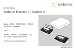
5
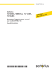
Equipment Supplied
The equipment supplied includes the components shown on the left:
6
-
Scale with platform and display unit
-
AG adapter
-
Dust cover
-
3 Allen wrenches
-
Retainers for mounting the display
-
2 M 4 x 8 screws and washers (for mounting the "Remote Display
Unit")
Installation Instructions
Ambient Conditions
Unfavourable ambient conditions can influence weighing results.
Therefore, please select a suitable place to set up
your scale. lt should not be exposed to the
following:
- heat radiation
- drafts
- vibrations
- aggressive chemical atmospheres (the scale must not be used in a
hazardous location/area)
Do not expose the scale to extreme moisture over long periods.
Moisture in the air can condense on the surfaces of a cold scale
whenever it is brought to a substantially warmer area. lf you need to
transfer the scale to a warmer area, make sure to condition it for
about 2 hours at room temperature, leaving it unplugged. Afterwards,
ifyou keep the scale connected to AC power, the continuous positive
difference in temperature between the inside of the scale and the
outside will practically ruie out the effects of moisture condensation.
The components used in the scale are rated to at least Class KSF
according to DIN 40040.
Your Sartorius scale provides accurate readouts even when it is
exposed to unfavorable ambient conditions.
You can adapt the scale to your requirements simply by changing the
code settings in the scale operating menu. For more information,
please read pages 21 through 23.
7
How to Mount the Display Unit
The display unit can be mounted as follows:
— base-mounted on the front of the scale
(factory-mounted)
— base-mounted on the side of the scale (see next page for directions)
— mounted as a remote display unit (see page 11)
— mounted on a support arm as a raised display unit; YDH 01 IB
is an Option (see page 13)
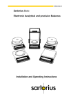
8
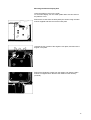
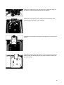
Mounting the Display Unit on the Short Side of Scale Base
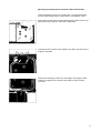
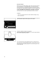
Leave the platform cover on the scale base. To mount the display,
turn the scale upside down so that it rests on the platform cover.
Remove the screws from the base plate using the Allen wrench supplied (see arrows) and then remove the base plate.
Unscrew the four screws of the angular cover plate, and remove the
angular cover plate.
Remove the fastening screws from the display unit using the Allen
wrench to untighten them. Remove the cable from the raceway
(channel).
9
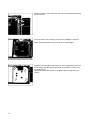
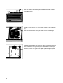
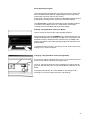
Attach the display unit to the short side of the scale base by tightening
the two screws.
Insert the cable in the raceway as shown in the diagram on the left.
Make sure that the rubber seal (see arrow) is not damaged.
Reposition the base plate and fasten it in place by tightening the three
M3x8 screws (see the large arrows) and the two M3x10 screws (see
the small arrows).
Afterwards, fasten the angular cover plate in place by tightening the
screws.
10
Mounting the Remote Display Unit
Leave the platform cover on the scale.
To mount the display, turn the scale upside down so that it rests on
the platform cover.
Remove the screws from the base plate (see arrows using the Allen
wrench supplied and then remove the base plate.
Unscrew the four screws of the angular cover plate, and remove the
angular cover plate.
Remove the fastening screws from the display unit using the Allen
wrench to untighten them. Remove the cable from the raceway
(channel).
11
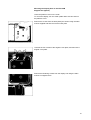
Attach the display unit to the mounting retainers supplied using the
two M4x8 screws and washers (can also be mounted on a wall for use
as a wall console).
Thread the cable through one of the three openings in the scale housing.
Make sure that the rubber seal (see small arrow) is not damaged.
Reposition the base plate and fasten it in place by tightening the three
M3x8 screws (see the large arrows) and the two M3x10 screws (see
the small arrows).
Afterwards, fasten the angular cover plate in place by tightening the
screws.
12
Mounting the Display Unit on the YDH 01IB
Support Arm (Option)
Leave the platform cover on the scale.
To mount the display, turn the scale upside down so that it rests on
the platform cover.
Remove the screws from the base plate (see arrows using the Allen
wrench supplied and then remove the base plate.
Unscrew the four screws of the angular cover plate, and remove the
angular cover plate.
Remove the fastening screws from the display unit using the Allen
wrench to untighten them.
13
Remove the four screws from the display unit (see arrows) using the
Allen wrench to untighten them.
Unscrew the two screws from the cable clamp.
Remove the clamp and then the display holder.
Remove the cable from the raceway in the bottom of
the scale.
Slide out the narrow cover plate of the support arm in the direction of
the arrow.
Use the Allen wrench to remove the four screws from the rectangular
support arm cover plate and remove the cover plate from the support
arm base.
Mount the display unit on the support arm using the two retainers and
the four screws supplied.
Route the cable through the cable conduit inside the support arm.
Mount the angular retainer using the screw and the spring washer so
that the bundle of shielded wires contacts the inside of the support
arm.
Insert the cable down through the support arm into opening of the
mounting frame. Afterwards, slide the narrow cover plate into the support arm.
Insert the cable in the raceway as shown in the diagram.
Make sure that the rubber seal (see arrow) is not damaged.
14
Fasten the support arm to the rear panel of the scale base using the
two M5x16 screws supplied and the star lock washers.
Attach the mounting frame of the support arm to the bottom of the
scale using the two M4x8 screws supplied.
Refasten the rectangular cover plate to the support arm using the four
screws.
Reposition the base plate and fasten it in place by tightening the three
M3x8 screws (see the large arrows ) and the two M3x10 screws (see
the small arrows).
15
Startup
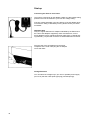
Connecting the Scale to Line Power
The scale is powered by an AC adapter. Make sure that voltage rating
printed on this unit is identical to your local line voltage rating.
lf the line voltage indicated or the plug design of the AC adapter does
not match the rating or Standard you use, please contact your Sartorius dealer.
Important Note
Only use original Sartorius AC adapters identified by the Sartorius label. Use of AC adapters supplied by other manufacturers, even if
these adapters have a registered approval rating from a national testing laboratory, requires the consent of a certified Sartorius technician.
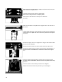
Plug the cord of the AC adapter into the power
receptacle of the scale. Now plug the AC adapter
into a wall outlet.
Voltage Selection
You can select the voltage only if you use our portable power supply
(69 71172) that has a European-type plug (rounded prongs).
16
Safety Precautions
The power supply or AC adapter rated to Class 2 (double insulated)
can be plugged into a wall outlet without taking any additional safety
precautions.
The negative pole (ground) of the Output voltage (protective extra-low
voltage) is connected to the scale housing, which can be grounded for
Operation.
The optional interface (see "Interfacing Devices" on page 26 in addition) is also electrically connected to the scale housing (ground).
Connecting Electronic Devices (Peripherals)
Unplug the AC adapter before you connect or disconnect devices to
or from the interface ports.
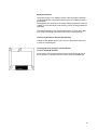
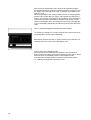
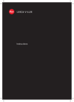
Leveling the Scale using the Level Indicator
(only for model IB 16000 S)
At the point of use, level the scale using the leveling feet (4) so that
the air bubble is centered within the circle of the level indicator (2).
17
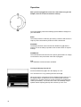
Operation
After you have plugged the scale into a wall outlet using the AC
adapter, allow for at least 30 minutes' warmup.
The weight display shows the following special Status messages for
your Information:
BUSY
The scale processor is still busy processing a function and will not accept any other commands to perform functions at this time.
STANDBY
The display has been turned off with the ON/OFF key (8) and the
scale is now in the ready-to-operate mode so that it does not require
warmup.
POWER OFF
The scale was disconnected from line power (power failure or outage,
reconnection to line power after scale was unplugged).
CAL
The calibration function has been activated.
Turning the Display On and Off
Press the ON/OFF key (8) to turn the display on or off.
You can also turn it on by pressing the tare control (6).
When the scale is connected to the AC adapter and the power is on,
the display will go out whenever you turn off the power using the
ON/OFF key. All other electronic circuits will remain energized (indicated by STANDBY). This means the scale is immediately ready to
operate without requiring warmup the next time you turn it on.
18
Self-Test
After the scale is turned on, an automatic self-test of the scale's electronic circuitry is performed.
This self-test ends with the readout 0.0 g/0.000 kg (if the factory code
setting 5 1 1/ 5 1 2 is used).
Weighing
Now place your sample or object on the platform (1) to determine the
weight. Read off the weight indicated in the display (9) as soon as the
weight unit (in this case "g") appears as the stability symbol.
In addition to grams/kilograms, this scale gives you a variety of
other menu-definable international weight unit options.
Select the weight unit you need from the table of the menu options for
the scale operating program. Set the appropriate code as described in
the section "Scale Operating Program."
Taring
lf you wish to weigh into a Container or if the weight display does not
indicate 0.0 g/0.000 kg (or the equivalent with the weight unit of your
choice), press the tare control to zero the display.
Auto Zero
This scale has an automatic zero tracking function, known as "Auto
Zero" (can be turned off by menu code - see "Scale Operating Program").
Changes off zero ≤ 0.5 of a digit per second are set to zero automatically.
19
Automatic Shutoff
Make sure the "Automatic Shutoff" code is set to "ON" when using a
non-rechargeable or rechargeable battery. This will increase the
amount of time you can operate the scale before having to recharge
the battery (see "Scale Operating Program"), lf you do not press a key
or if a weight readout in the display does not change for at least 2
minutes, "STANDBY" will start flashing in the display. The scale will
shut itself off if it has not been operated after another 2 minutes.
Calibration
— This is only possible with an accurate calibration weight (10 kg)
— See "Accessories" Unload the scale and press the CAL key (7) for at least 3 seconds until the calibration weight readout appears in the display.
Center the calibration weight on the platform.
Now the weight unit symbol is displayed. An acoustic signal indicates
the end of the calibration procedure.
You can block access to the calibration function -to find this menu
code, refer to the "Scale Operating Program." This function is accessible when the scale operating program is unlocked using the menu
access switch (5).
20
Scale Operating Program
The scale operating program lets you adapt your scale to various ambient conditions and to different weighing requirements, and select
weight units commonly used in your country.
At the factory, we have set the codes for a Standard program which is
protected by a locking function to prevent accidental changes.
The "menu code" contains the information of the operating program,
lt consists of three digits, known in "computerese" as the page
(1st digit), the line (2nd digit) and the word (3rd digit).
Reading a Program Menu Code (List Mode)
How to access the menu of the scale operating program:
With the display turned off (STANDBY state), hold down the tare control (6) and briefly press the ON/OFF key (8). Upon completion of the
automatic self-test, release the tare control as soon as "CH5" is displayed. The Status of the scale operating program is indicated in the
weight display:
"L" Stands for the list mode. In this mode, you can read a menu code
setting, but you cannot change it.
Changing a Program Menu Code (Change Mode)
lf you wish to change a program menu code, you must first unlock the
menu access switch to access the program menu.
To do so, remove the protective cover located on the right of the display unit, and slide the menu access switch (5) in the direction of the
arrow.
The display will indicate "C", which Stands for the change mode,
meaning you can now change the menu code settings.
21
After you have accessed the menu of the scale operating program,
the display will show a continuous numerical sequence from 0 to 5 for
the "page" or the first digit of the code, in addition to the Status code
letter "L" or "C".
When the first digit of the code you wish to check or change appears,
press the tare control (6). The "page" code number now stops in the
display, and a series of numbers for the 2nd digit or ''line" will begin to
cycle. Press the tare control again to stop the code number of your
choice in the display. Next, the numbers for the "word" (last digit) will
cycle in the display. Repeat the procedure to enter the last digit of the
code.
The "o" symbol that appears indicates the actual setting.
To change any settings ("C" mode), press the tare control as soon as
the appropriate numeric code is displayed.
Brief display of BUSY and the "o" symbol confirms your selection, followed by a return to "zero" for the 2nd digit or "line."
How to return to the weighing mode:
Press the tare control each time a 0 appears in the numerical sequence (word, line, page). lf you have changed a menu code, it will be
stored as soon as the display returns to the weighing mode.
Lock the scale operating program using the menu access switch
("L" readout) and replace the protective cover.
22
List of the Programmable menu Code Settings
C 1 3 1
Page
Line
Word
Menu of the Balance Operating Program
(Active Parameters)
Code
C
C
C
C
1
1
1
1
1
1
1
1
1
2
3
4
Code
C
C
C
C
C
C
C
C
C
1
1
1
1
1
1
1
1
1
2
2
2
2
2
2
2
2
2
1
2
3
4
5
6
7
8
9
Stability Range
0,25 digit
0,5 digit
1
digit
2
digits
4
digits
8
digits
16
digits
32
digits
64
digits
3
3
3
3
1
2
3
4
Display Format
Last decimal ON
Last decimal OFF
Last decimal at stability
All decimals at stability
Code
C
C
C
C
1
1
1
1
Ambient Conditions
Very stable
Stable
Unstable
Very unstable
Code
C 1 4 1
C 1 4 2
Code
C 1 5 1
C 1 5 2
Code
C 1 6 1
C 1 6 2
Tare parameter
Without stability
At stability
Code
C 4 1 1
C 4 1 2
Code
Program Lock
OFF
ON
C 4 3 1
C 4 3 2
Acoustic Signal
ON
OFF
Code
C 5 1
C 5 1
C 5 1
C 5 1
c 5 1
c 5 1
c 5 1
c 5 2
c 5 2
c 5 2
c 5 2
c 5 2
c 5 2
c 5 2
C 5 2
Weight Units )
Grams
Kilograms
Carats
Pounds
Ounces
Troy ounces
Parts/pound
Hong Kong taels
Singapore taels
Taiwan taels
Grains
Pennyweights
Mommes
Milligrams
Austrian carats
1
1
2
3
4
5
6
7
1
2
3
4
5
6
7
8
g
kg
ct
lb
oz
ozt
o
tl
tl
tl
gr
dwt
o
o
o
Auto Zero
ON
OFF
Calibration
Accessible
Accessible blocked
C 5 2 0
C 5 0
Call Program Line
Call Program page
C 0
End of programming
Additional Parameters for the data Output format at the interface port and for calculation programs are
available on request.-Please refer to the “Accessories."
1)
You can choose any weight unit as long as it can be displayed in the particular weighing range you
selected (for example do not set the code for "kg" when you are using a 0.1 mg balance).
23
Troubleshooting Guide
Problem ...
Causes ...
No segments are indicated in the
weight display (9)
-
Weight display shows “L” or
“CH2”
-
Weight display shows “H”
The weight readout changes
constantly or the special message
“BUSY” does not go out in the
weight display
-
The weight display shows “CE”
-
The code “CC“ in the display does not go out
The weight readout is obviously
wrong
-
“POWER OFF”
blinks in the display
24
-
No line voltage available
The AC adapter is not plugged
in
The platform cover (1) is not in
place
An object is pressed against
the platform cover or has
gotten underneath it
Load exceeds the capacity of
the scale
Unstable ambient conditions
Too much vibration or there is
a draft
Sample does not have a stable
weight
A zero readout was not
indicated in the weight display
when the CAL key (11) was
pressed to calibrate
The scale is loaded
The CAL key (7) has not been
pressed when the display read
zero
The scale is loaded
Scale has not been calibrated
Scale has not been tared
before weighing
The air bubble of the level
indicator (2) is not within the
circle(only for IB 16000 S)
The operating voltage is too
loo
(battery discharged)
Remedy
-
Check power supply
Plug in the AC adapter
Place platform cover on the
scale base
The platform cover must rest
properly on the scale base
without any interfering objects
in between
-
Unload the scale
-
Set up scale in another area
Access the menu to adapt
scale to the particular type of
weighing environment
-
Press tare control (9) and repress the CAL key
-
Press the tare control (6) and
re-press the CAL key
-
Unload the scale
Calibrate scale
Tare before weighing
-
Level scale
-
Connect the scale or the
external rechargeable battery
to line voltage using the AC
adapter
Care and Maintenance
Cleaning
Please do not use any aggressive cleaning agents (solvents or similar
agents). Instead, use a piece of cloth that has been wet with a mild
detergent to clean the scale. Make sure that no liquid enters the scale
housing. After cleaning, wipe down the scale with a soft, dry piece of
cloth.
Safety Inspection
lf there is any indication that safe Operation of the scale with the AC
adapter/power supply is no longer warranted, turn off the scale and
disconnect the equipment from AC power immediately. Lock the
equipment in a secure place to ensure that it cannot be used for the
time being.
In this case, notify the Sartorius Service Center or International Technical Support Group based in Goettingen, Germany. Only service
technicians who are authorized by Sartorius and have access to the
required manuals are allowed to perform maintenance and repair
work on the equipment.
Safe Operation of the scale with the AC adapter/power supply is no
longer ensured when
—
—
—
—
there is visible damage to the AC adapter/power supply
the AC adapter/power supply no longer functions properly
the AC adapter/power supply has been stored for relatively
long periods under unfavourable conditions
the AC adapter/power supply has been exposed to rough
handling during shipment
We recommend that the scale along with the AC adapter/power supply be inspected by a qualified Sartorius service technician according
to the checklist given below.
—
—
Leakage current <0.05 mA measured by a properly calibrated
multimeter
Insulation resistance >7 megohms measured with a constant
voltage of at least 500 V at a500kohmload.
The duration and number of measurements should be
determined by a qualified Sartorius service technician
according to the particular ambient conditions
and operational conditions of the AC adapter. Such
inspection should be done at least once a year.
25
Accessories (Options)
Data printer with
date/time and statistics functions
Print speed approx. lines/sec.
Printer housing (W x D x H) in mm
in inches
YDP 02-0D
Interface
“Data Input” (incl. interface)
Dedicated applications kit for the YDI 11 IB
(incl. interface)
Replace & with the letter code:
C for parts counting
F for formulation
A for animal weighing
U for the PLUS Performance Package
Support arm (for raised display unit
Rechargeable battery pack,
external; approx. 10 hours of operation;
can be recharged by the AC adapter
(detailed information for powering the scale is
available in our Service Information bulletin,
no. 15/88)
Adapter for hook-up to a 12-Volt battery
Roller track conveyer plate
Remote display (can be connected to the
interface port)
— LCD, reflective
— for overhead projectors, transmissive
Calibration weight ( 1 x 10 kg)
Dust cover
YDO 01 IB
YDI 11 IB
YAK 11 I-000&
1,5
150 x 138 x 43
5.5 x 5.4 x 1.7
YDH 01 IB
YRB 02 Z
YCC 01-0007
YRT 01 IB-0001
7371 01A
7371 02A
7072 18
69 60I310
Interfacing Devices with the Scale
Please note that the interface port is electrically connected to the protective grounding conductor of the scale housing. The cabling supplied as accessory components is shielded and electrically connected
on both ends to the cases of the connectors. This electrical connection may result in interference caused by ground loops or by
transient currents if you have grounded the housing or connected the
protective grounding conductor for AC power. lf necessary, connect
an equipotential bonding conductor to the scale.
26
Specifications
Model
Capacity
Readability
Maximum overload capacity
Tare range (by subtraction)
Standard deviation
Max. linearity deviation
Stabilization time (typical)
kg
g
kg
kg
IB 16000 S
16,1
0,1
75
16,1
IB 31000 P
4/8/16/31
0,1/0,2/0,5/1
75
31
IB 31
31
1
75
31
g
g
s
≤±0,05
≤±0,2
2
≤±0,1/0,1/0,25/1
≤±0,2/0,2/0,5/1
≤±0,5
≤±1
Adaption to ambient conditions
and application requirements
by selection of one of four digital filter levels
Display update rate
Stability range
Ambient temperature range
Moisture-proof rating according
to DIN 40040
Dust and water protection rating in
compliance with DIN 40050/IEC 529
o
Sensitivity drift within +10 ... +30 C
Platform size
Scale base (W x D x H)
s
d
Net weight of the scale
Net weight of the display unit
Power requirements (voltage +
frequency: 50 – 60 Hz)
Allowable voltage fluctuation
Power consumption
Interface (optional)
kg
kg
mm
mm
VA
0,1 – 0,8 (selectable)
0,25 … 64 (selectable)
o
o
o
o
0 . C.. +40 C (32 F … 104 F)
Class F, non-condensing
IP 65 (scale) = NEMA 4
IP 20 (AC adapter)
-6
-6
-6
≤±2,5∙10
≤±4∙10
≤±10∙10
417 x 307 (16.4 x 12.1 in.)
417 x 307 x 113
(16.4 x 12.1 x 4.4 in.)
(without display unit)
15 (33 lbs.)
1 2.2 lbs.)
115 or 230 V depending on the AC adapter used
-20% ... +15%
9 (typical)
RS 232 C/V24 – 28, RS 423/V10; 7-bit;
parity: even, mark, odd, space;
transmissions rate: 150 ... 9600 Baud
27
Sartorius AG
B
P
T
37070 Göttingen
Weender Landstraße 94–108, 37075 Göttingen
(0551) 308-0, F (0551) 308-3289
Internet: http://www.sartorius.com
Copyright by Sartorius AG, Göttingen, Deutschland.
All rights reserved. No part of this publication may be
printed or translated in any form or by any means without
the prior written permission of Sartorius AG.
Sartorius AG reserves the right to make change to the
technology, features, specification and design of the equipment
without notice.