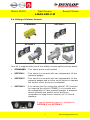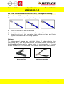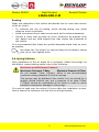
1
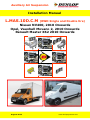
Auxiliary Air Suspension Installation Manual L.MAS.10D.C.M (RWD Single and Double tire) Nissan NV400, 2010 Onwards Opel, Vauxhall Movano 2, 2010 Onwards Renault Master X62 2010 Onwards August 2012 www.dunlopsystems.com Nissan NV400 Opel Movano Renault Master L.MAS.10D.C.M CONTENTS 1. 2. 3. 4. 5. FOREWORD .......................................................... INTRODUCTION .................................................... VERY IMPORTANT NOTES ........................................ OVERVIEW ........................................................... INSTRUCTIONS FOR INSTALLATION ......................... 3 4 5 6 7 5.1. Recommended Tightening Torque.................................................. 7 5.2. Installation of the air suspension at the left side .............................. 8 5.3. Installation of the air suspension at the right side ............................ 8 5.4. Fitting of Inflator Console ............................................................. 9 5.5. Tube Connection and Disconnection, Cutting and Routing ............... 11 5.6. Spring Inflation......................................................................... 12 5.7. Spring Alignment ...................................................................... 13 5.8. Maintenance............................................................................. 13 5.9. Check list ................................................................................. 14 5.10. Installation Drawings ............................................................... 15 6. EPILOGUE ............................................................ 16 Dunlop Systems and Components Het Wegdam 22 7496 CA Hengevelde Nederland Tel. +31 (0)547 33 30 65 Fax. +31 (0)547 33 30 68 Dunlop Systems and Components Holbrook Lane Coventry CV6 4QX United Kingdom Tel. +44 (0)24 7629 3300 Fax. +44 (0)24 7629 3390 www.dunlopsystems.nl © 2008, Dunlop Systems and Components 2 www.dunlopsystems.com Nissan NV400 Opel Movano Renault Master L.MAS.10D.C.M 1. FOREWORD This manual provides instructions for the installation of an auxiliary air suspension kit, developed specifically for the Renault Master X62, Opel/ Vauxhall Movano 2 and Nissan NV400 (2010 onwards) rear wheel drive double tire and single tire. To ensure correct installation of the kit, it is strongly recommend that these instructions are read thoroughly before commencing any installation work. Installation should only be carried out by a suitably qualified mechanic or specialist installation facility. Dunlop Systems and Components will not accept any responsibility for faults or defects arising from incorrect installation, which automatically renders the guarantee invalid. IMPORTANT : Manufacturer’s Declaration Form A manufacturer’s declaration form is provided with your kit. Following installation of the kit please ensure that this form is completed and signed by a qualified fitter, and that a copy is returned to Dunlop Systems and Components by post, fax or email. 3 www.dunlopsystems.com Nissan NV400 Opel Movano Renault Master L.MAS.10D.C.M 2. INTRODUCTION Thank you for choosing an auxiliary air suspension kit from the range offered by Dunlop Systems and Components. Auxiliary air suspension is fitted in tandem with the standard steel springs of the vehicle suspension, and provides enhancements in terms of both the stability of the vehicle and the comfort of the passengers… Vehicle Levelling Simply by varying the air pressure in the springs, the vehicle can be levelled both front-to-rear and side-to-side. Keeping the vehicle level optimises stability, ensures correct headlamp beam distribution and reduces tyre wear arising from uneven distribution of weight. Straight Line Stability Straight line stability is greatly increased at higher speeds, and when subjected to buffeting from cross-winds or large overtaking vehicles. Reduced Body Roll Body roll when cornering or negotiating roundabouts is significantly reduced. Fatigue Reduction and Wear Compensation Suspension fatigue is reduced, so helping to prevent leaf springs from sagging under repeated or constant loading. Any sagging already present can be compensated-for. This is a particular benefit for motorhomes, which are always fully laden. Ride Comfort Air springs help to absorb shock loads from uneven road surfaces, therefore general ride quality is much improved. 4 www.dunlopsystems.com Nissan NV400 Opel Movano Renault Master L.MAS.10D.C.M 3. VERY IMPORTANT NOTES Gross Vehicle Weight (GVW) Air assist kits are not in themselves designed to increase the gross vehicle weight (GVW) rating of a vehicle. They do not legally allow for carriage of a load greater than the carrying capacity stated on the data plate of the vehicle. Do not exceed the maximum load specified by the vehicle manufacturer… to avoid compromising passenger safety to prevent possible damage to the vehicle for legal reasons Vehicle Uprating Despite the above words of caution, it is possible to upgrade the weight rating of your vehicle. This must be carried-out by a specialist supplier that will… carry out any necessary modifications in addition to fitting the air assist kit complete documentation as necessary to inform the Vehicle and Operator Services Agency (VOSA) – a mandatory requirement supply and fit a new weight plate to replace the original plate supplied with the vehicle This process applies to United Kingdom registered vehicles. The process in other countries may be different. Safety Guidance Note The following very useful guidance note is available for free download from the Health and Safety Executive (HSE)… PM85, July 2007 Safe recovery (and repair) of buses and coaches fitted with air suspension The uniform resource locator (URL) for this document is… http://www.hse.gov.uk/PUBNS/pm85.pdf 5 www.dunlopsystems.com Nissan NV400 Opel Movano Renault Master L.MAS.10D.C.M 4. OVERVIEW The diagram below is an overview of the complete assembly... POS 1 2 3 4 5 6 7 8 9 10 ARTIKEL NUMBER OP.LB.170‐2.CPL 65.05.00.1.01 DIN 933‐M8x16 DIN 933‐M8x25 65.06.00.1.04.01 65.06.00.1.04.02 DIN 7991‐M8x12 DIN 125A‐M8 DIN 985‐M8 DESCRIPTION 170/2 AIR BELLOW UPPER BRACKET DISC SPRING WASHER 8 x 13 HEXAGON BOLT M8 x 16 HEXAGON BOLT M8 x 25 LOWER PLATE FIXATION BRACKET LOWER PLATE M8 x 12 COUNTER SUNK BOLT WASHER M8 SELF LOCKING NUT M8 AMOUNT 2 2 4 4 4 2 2 4 4 4 The kit is also supplied with black and blue air hose and an inflation possibility (See Section 5.4) 6 www.dunlopsystems.com Nissan NV400 Opel Movano Renault Master L.MAS.10D.C.M 5. INSTRUCTIONS FOR INSTALLATION Preparation and Precaution Before beginning installation, ensure that you have sufficient clearance between the axle and the chassis (at least 25cm). Use a jack if necessary. Install at one side of the vehicle at a time. Pay attention to your safety at all times during installation always use axle stands to support the vehicle! Start by jacking up the rear side till approximately driving level and measure the distance between the rear axle and the chassis at the location of the bump stop. This should be app. 14 cm. If this is app. 18 cm you will need a 3convolute air bellow. 5.1 Recommended Tightening Torque During fitting of the air suspension system, it is recommended that nuts and bolts are tightened in accordance with the following table... METRIC TORQUE CHART in N.m Aluminium SIZE CLASS 8.8 CLASS 10.9 and PA6G When both the bolt and nut are made M6 x 1 M8 x 1.25 M10 x 1.25* M10 x 1.5 M12 x 1.75 M16 x 2 For all other materials, tightening 10 23 51 48 83 200 14 34 72 67 117 285 4 9 20 18 31 80 from steel use either class 8.8 or 10.9 torque is left to the discretion of a person skilled in the art 7 www.dunlopsystems.com Nissan NV400 Opel Movano Renault Master L.MAS.10D.C.M The following instructions make reference to the diagrams on pages 14 to 16 inclusive. 5.2 Installation of the air suspension at left side 1. Remove the bump stop. You can easily push the bump stop out of it’s holder. The M10 bolt is to be reused for the mounting of the upper bracket (Photo 1—7). 2. Now there is space created to install the lower plate and air bellow. 3. Attach the lower plate with two M8 x12 counter sunk bolts (Photo 8), take care that the air nipple will be at the inside of the chassis. 4. Lift the rear side of the assembly a bit (Photo 9) so you can easily shift the assembly from the inside on it’s place (Photo 10—11). 5. The integrated clamps will keep the assembly on it’s place, they have to be in between the two ribs of the anti roll bar bracket (Photo 12). 6. The middle stop positions the plate (Photo 12). 7. Now install the little bracket at the other side of the lower plate with the two hexagon M8 x 25 bolts, washers and nuts (Photo 13—18). 8. Also this little bracket has to be in between the two ribs of the anti roll bar bracket (Photo 18). 9. Install the upper bracket with it’s original bolt (Photo 6, 19 & 20). The hole to guide the air hose trough has to be on the inside. 10. Remove the plug (Photo 21). 11. Guide the black air hose through the hole on the inside and connect it to the air bellow (Photo 22, 23). Caution! Don’t tighten the special nut of the air line not to tight (See Section 5.5). 12. Bring the air bellow into position on the rear axle and install both M8 bolt with disc washer finger tight at the top side. (see Photo 24). 13. Before tightening all bolts and nuts definitely, install the right side. 5.3 Installation of the air suspension at the right side 1. Item 1 till 12 are identical to the left side (accept that the right side we use blue hose and of course is the right side mirror wise). 14. Bring the vehicle till driving height (when the vehicle is almost totally empty you have to bring weight into the vehicle). Driving height is app. 13.5 cm, of course can this height be modified a little on request of the Vehicle owner. 15. Before tightening all bolts and nuts definitely (See section 5.1), the air bellow needs to be aligned. (See Section 5.7) 16. Now you can guide the air hoses (See Section 5.5) 8 www.dunlopsystems.com Nissan NV400 Opel Movano Renault Master L.MAS.10D.C.M 5.4 Fitting of Inflator Console STANDARD OPTION 1 OPTION 2 OPTION 3 Your kit is supplied with one of the inflator console options shown above… STANDARD : Two valves and a small bracket OPTION 1 : Two valves in a console with two independent 10-bar pressure gauges OPTION 2 : Two valves in a console with two independent 10-bar pressure gauges and a rocker on/off switch to operate the electric motor driven air compressor OPTION 3 : Four valves (two for raising the vehicle (’UP’) and two for lowering the vehicle (’DOWN’)) in a console with two independent 10-bar pressure gauges. A pressure switch operates the electric motor driven air compressor to keep the air reservoir of 2.2-litre at pressure. A special dashboard panel is available for OPTION 1 and OPTION 2 9 www.dunlopsystems.com Nissan NV400 Opel Movano Renault Master L.MAS.10D.C.M Mount the console in a position of your choice whereby it is firmly fixed, has some protection from the environment (particularly important for the console with gauges) and is easily accessible. Suggested possible locations include... ‘Standard’ Console… on the rear bumper at the rear beside the license plate on the chassis next to a rear wheel in a service shutter (motorhomes) beside the fuel cap ‘Option 1’, ‘Option 2’ or ‘Option 3’ Console… in the vehicle cabin, within reach and sight of the driver Beside, under the driver seat in the wall of a cupboard (motorhomes) in a service shutter (motorhomes) ‘Comfort’ Packages The ‘Option 2’ and ‘Option 3’ panels, as shown above, are each part of a Comfort Package that is supplied with a compressor (and also an air reservoir in the case of the ‘Option 3’ panel) for ease of spring inflation and ride height setting. For further information please ask your dealer. The photograph below shows all of the parts of Comfort Package ‘Option 2’... Comfort Package ‘Option 2’ 10 www.dunlopsystems.com Nissan NV400 Opel Movano Renault Master L.MAS.10D.C.M 5.5 Tube Connection and Disconnection, Cutting and Routing Connection and Disconnection Tubes are connected as shown by the diagrams below... A A. B. C. B C Slide a nut over the end of the tube Push the tube onto the connector as far as possible Feed the nut up to the connector, fully tighten by hand and finally tighten one additional turn using spanners Cutting To achieve good sealing and air-tight fitting of tube ends to their connecting parts, it is very important to cut tubing cleanly and squarely. A dedicated guillotine action tubing cutter is recommended, or a craft knife if such a tool is not available. Do not use electrician’s side cutters. A dedicated tubing cutter Recommended Electrician’s Side Cutters NOT Recommended 11 www.dunlopsystems.com Nissan NV400 Opel Movano Renault Master L.MAS.10D.C.M Routing Study the underside of the vehicle and decide how to route each branch of the air circuit… To minimise the risk of chafing, avoid running tubing over metal edges as much as possible Avoid close proximity to heat sources such as the exhaust assembly Choose a route that provides as much protection as possible from dirt, debris and any solid objects that may impact the underside of the vehicle It is recommended that tubes are guided alongside brake lines as much as possible. Use cable ties (‘tie wraps’) to secure tubing to the chassis, taking care not to over-tighten them. 5.6 Spring Inflation Once installation of the air assist kit is complete, inflate the springs via the inflator console taking careful note of the following... Maximum and Minimum Pressure Maximum Pressure 7.0bar Minimum Pressure 0.5bar Do not exceed 7.0bar (101psi), which is the recommended maximum charge pressure for the air springs. The springs may be deflated if the vehicle is to be stored for a lengthy period without use, but a pressure of at least 0.5bar (7.25psi) should be maintained at all times in order to avoid possible compression damage to the springs. It is wise to hand over the vehicle 24 hours after the installation is done. Just to assure the customer will leaf with an airtight system. 12 www.dunlopsystems.com Nissan NV400 Opel Movano Renault Master L.MAS.10D.C.M 5.7 Spring Alignment Spring out of alignment mounting plate axes offset Spring in alignment mounting plates parallel and coaxial CAUTION! Before fully tightening the bolts that secure the air spring to the upper and lower brackets, set the vehicle at ride height (spring height approximately 13.5cm) and ensure that the springs are correctly aligned. 5.8 Maintenance Following installation, it is recommended that all metal parts are coated with a protective substance such as body wax. The system does not require very much maintenance other than… to maintain air pressure in the springs. Much like a tyre, the system may lose a little air over time. to keep the air bellows clean. It is suggested that, when washing the vehicle, the bellows are inspected and cleaned as necessary (preferable by spraying). Look in particular for stones or grit trapped between convolutes, as this may damage the bellow. Check before and after the winter period the wax coating. Re-wax when necessarily 13 www.dunlopsystems.com Nissan NV400 Opel Movano Renault Master L.MAS.10D.C.M 5.9 Check List Before driving the vehicle following completion of installation of the auxiliary air suspension system, please check... ...all bolts tightened to the recommended torque (Page 8)? 2 ...air springs set in alignment (Section 5.4)? ...enough free space around the air springs to avoid wearing? ...all metal parts wax coated (Section 5.5)? ...manufacturer’s declaration form completed and a copy returned? A wait of 24 hours is recommended in order to ensure that the vehicle has maintained its stance and that there are no air leaks present. 14 www.dunlopsystems.com Nissan NV400 Opel Movano Renault Master L.MAS.10D.C.M 5.10 Installation Drawings 15 www.dunlopsystems.com Nissan NV400 Opel Movano Renault Master L.MAS.10D.C.M 1 2 3 4 5 6 7 8 16 www.dunlopsystems.com Nissan NV400 Opel Movano Renault Master L.MAS.10D.C.M 9 10 11 12 13 14 15 16 17 www.dunlopsystems.com Nissan NV400 Opel Movano Renault Master L.MAS.10D.C.M 17 18 19 20 21 22 23 24 18 www.dunlopsystems.com Nissan NV400 Opel Movano Renault Master L.MAS.10D.C.M 6. EPILOGUE Dunlop Systems and Components hopes that you enjoy the benefits that your air suspension system will provide for you. To ensure optimal performance, we advise that you have your system checked frequently by qualified personnel. As recommended in the fitting instructions, it is important to coat all the steel parts with a protective substance such as body wax. IMPORTANT : Manufacturer’s Declaration Form A manufacturer’s declaration form is provided with your kit. Following installation of the kit please ensure that this form is completed, signed by a qualified fitter and a copy is returned to Dunlop Systems and Components by fax, post or e-mail. As a condition of your warranty, modifications to the system may only be carried out by personnel of Dunlop Systems and Components or an appointed agent. Enquiries For general enquiries please either telephone… Dunlop Systems and Components Nederland : +31 (0)547 33 30 65 Dunlop Systems and Components UK : +44 (0)24 7629 3300 ...or e-mail [email protected] or [email protected]. 19 www.dunlopsystems.com Auxiliary Air Suspension Dunlop Systems and Components Het Wegdam 22 7496 CA Hengevelde Nederland Tel. +31 (0)547 33 30 65 Fax. +31 (0)547 33 30 68 Dunlop Systems and Components Holbrook Lane Coventry CV6 4QX United Kingdom Tel. +44 (0)24 7629 3300 Fax. +44 (0)24 7629 3390 www.dunlopsystems.com