1
Owner's Manual
ICRAFTSMAN°I
AC Generator
Model No
580.325600
GENERATOR
CUSTOMER
HELPLINE
J
1"800__
HOURS:
Mono-FrL8am
"_
toSpm
(CT)
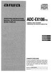
CAUTION
PRECAUCION
Before using this product, read this
Antes de utilizar el producto, tea este
manual and follow all Safety Rules
manual y siga todas las Reglas de
and Operating Instructions.
Seguridad e Instrucciones de Uso.
Sears, Roebuck
and Co, Hoffman
Estates,
visit our Craftsman website: www craftsman com
Part NO 191559GS
Draft 10 (03/01/2005)
IL 60179
USA.
•
•
•
•
•
Safety
Assembly
Operation
Maintenance
Parts
•
Espa_ol
WARRANTY
....................................
SAFETY RULES
FEATURES AND CONTROLS
ASSEMBLY
OPERATION
2
...............................
3-4
......................
5
...................................
6-7
.................................
8-11
SPECIFICATIONS
MAINTENANCE
...............................
12
..............................
13-15
STORAGE .....................................
LIMITED
16
WARRANTY
TROUBLESHOOTING
SCHEMATIC
............................
17
DIAGRAM ..........................
18
WIRING DIAGRAM ..............................
REPLACEMENT
NOTES
19
PARTS .......................
20-28
.......................................
29
EMISSION CONTROL WARRANTY
..............
30-31
ESPAi_IOL ...................................
32-51
HOW TO ORDER PARTS ................
FOR DELUXE
PORTABLE
BACK PAGE
GENERATORS
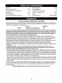
SEARS warrants to the original purchaser that the alternator and engine for its portable generator will be free
from defects in materials or workmanship for the items and period set forth below from the date of original
purchase. This warranty is not transferable and applies only to portable generators driven by the Sears
warranted engine.
Alternator
Engine
CONSUMER*
2 years (2nd year parts only)
2 years (2nd year parts only)
COMMERCIAL*
1 year
1 year
* NOTE: For the purpose of this warranty "Consumer Use" means personal residential household and
emergency use by original purchaser, not to be used as a primary source of power. "Commercial Use" means all
other uses, including rental, construction, commercial, and income producing purposes. Once a generator has
experienced commercial use, it shall thereafter be considered a commercial use generator for the purpose of
this warranty.
During said warranty period, SEARS will, at its option, repair or replace any part which, upon examination by
SEARS, is found to be defective under normal use and service**. Starting batteries are not warranted by
SEARS. All transportation costs under warranty, including return to the factory if necessary, are to be borne by
the purchaser and prepaid by him. This warranty does not cover normal maintenance and service and does not
apply to a generator set, alternator or engine, or parts which have been subjected to improper or unauthorized
installation or alteration, misuse, negligence, accident, overloading, overspeeding, improper maintenance, repair
or storage so as, in SEARS's judgment, to adversely affect its performance and reliability.
** NORMAL WEAR: As with all mechanical devices, engines need periodic parts service and replacement to
perform well. This warranty will not cover repair when normal use has exhausted the life of a part or engine.
THERE IS NO OTHER EXPRESS WARRANTY. SEARS HEREBY DISCLAIMS ANY AND ALL
IMPLIED WARRANTIES, INCLUDING BUT NOT LIMITED TO THOSE OF MERCHANTABILITY
AND FITNESS FOR A PARTICULAR PURPOSE TO THE EXTENT PERMITTED BY LAW. THE
DURATION OF ANY IMPLIED WARRANTIES WHICH CANNOT BE DISCLAIMED IS LIMITED TO
THE TIME PERIOD AS SPECIFIED IN THE EXPRESS WARRANTY. LIABILITY FOR
CONSEQUENTIAL, INCIDENTAL, OR SPECIAL DAMAGES UNDER ANY AND ALL WARRANTIES
IS EXCLUDED.
Some states do not allow limitations on how long an implied warranty lasts, or the exclusion or limitation of
incidental or consequential damages, so the above limitations or exclusions may not apply to you. This warranty
gives you specific legal rights and you may also have other rights, which vary from state to state.
For service, see your nearest SEARS authorized warranty service facility. Warranty service can be performed
only by a SEARS authorized service facility. This warranty will not apply to service at any other facility. At the
time of requesting warranty service, evidence of original purchase date must be presented.
SEARS,
ROEBUCK
© Sears, Roebuck and Co.
AND CO., Dept. D/817 WA, Hoffman
Estates,
IL 60179 U.S.A
_IL
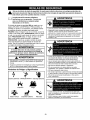
This
safety
alert symbol.
It is used
alert you
to potential
personal
injury
hazards.
Obey isallthe
safety
messages
that follow
this to
symbol
to avoid
possible
injury or
death.
_Read
familiar
this manual carefully and become
with your generator.
Know its
applications,
involved.
its limitations,
WARNING
and any hazards
The safety alert symbol (,A) is used with a signal
word (DANGER, CAUTION, WARNING), a pictorial
and/or a safety message to alert you to hazards.
DANGER indicates a hazard which, if not avoided, will
result in death or serious injury, WARNING indicates a
hazard which, if not avoided, could result in death or
serious injury, CAUTION indicates a hazard which, if
not avoided, might result in minor or moderate injury.
CAUTION, when used without the alert symbol,
indicates a situation that could result in equipment
damage, Follow safety messages to avoid or reduce
the risk of injury or death.
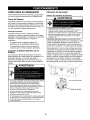
Operate generator ONLY outdoors.
Keep exhaust gas from entering a confined area through
windows, doors, ventilation intakes or other openings.
DO NOT operate generator inside any building or
enclosure, including the generator compartment of a
recreational vehicle (RV).
WARNING
The engine exhaust from this product contains
chemicals known to the State of California to cause
cancer, b rth defects, or other reproductive
harm.
WARNING
This generator does not meet U. S. Coast Guard
Regulation 33CFR-183 and should not be used on
marine applications.
Failure to use the appropriate U. S. Coast Guard
approved generator could result in bodily injury and/or
property damage.
Hazard
Symbols
and Meanings
When using generator for backup power, notify utility
company. Use approved transfer equipment to isolate
generator from electric utility.
Use a ground circuit fault interrupter (GFCI) in any damp
or highly conductive area, such as metal decking or steel
work.
DO NOT touch bare wires or receptacles.
DO NOT use generator with electrical cords which are
worn, frayed, bare or otherwise damaged.
DO NOT operate generator in the rain.
DO NOT handle generator or electrical cords while
standing in water, while barefoot, or while hands or feet
are wet.
DO NOT allow unqualified persons or children to operate
or service generator.
WARNING
Electrocution
Electrical
Shock
Explosion
Toxic Fumes
Electrical
Shock
Fire
Hot Surface
When starting engine, pull cord slowly until resistance is
felt and then pull rapidly to avoid kickback.
NEVER start or stop engine with electrical devices
plugged in and turned on.
Kickback
WARNING
WHEN ADDING OR DRAINING
WARNING
FUEL
Turn generator OFF and let it cool at least 2 minutes
before removing fuel cap. Loosen cap slowly to relieve
pressure in tank.
Fill or drain fuel tank outdoors.
WHEN ADJUSTING
OR MAKING REPAIRS TO YOUR
ENERATOR
Disconnect the spark plug wire from the spark plug and
place the wire where it cannot contact spark plug.
WHEN TESTING FOR ENGINE SPARK
DO NOT overfill tank. Allow space for fuel expansion.
Use approved spark plug tester.
Keep fuel away from sparks, open flames, pilot lights,
heat, and other ignition sources.
DO NOT check for spark with spark plug removed.
DO NOT light a cigarette or smoke.
VHEN STARTING EQUIPMENT
CAUTION
Ensure spark plug, muffler, fuel cap and air cleaner are
in place.
DO NOT crank engine with spark plug removed.
If fuel spills, wait until it evaporates
engine.
VHEN OPERATING EQUIPMENT
before starting
Do not tip engine or equipment at angle which causes
fuel to spill.
DO NOT choke carburetor to stop engine.
This generator is not for use in mobile equipment or
marine applications.
VHEN TRANSPORTING OR REPAIRING EQUIPMENT
Transport/repair with fuel tank EMPTY or with fuel shutoff
valve OFF.
Disconnect spark plug wire.
VHEN STORING FUEL OR EQUIPMENT WITH FUEL IN
TANK
Store away from furnaces, stoves, water heaters, clothes
dryers or other appliances that have pilot light or other
ignition source because they can ignite fuel vapors.
DO NOT tamper with governed speed. Generator
supplies correct rated frequency and voltage when
running at governed speed.
DO NOT modify generator in any way.
CAUTION
See "Don't Overload Generator".
Start generator and let engine stabilize before connecting
electrical loads.
Connect electrical loads in OFF position, then turn ON
for operation.
Turn electrical loads OFF and disconnect from generator
before stopping generator.
CAUTION
WARNING
Use generator only for intended uses.
If you have questions about intended use, ask dealer or
contact Sears.
Operate generator only on level surfaces.
DO NOT touch hot surfaces.
Allow equipment to cool before touching.
The generator must be at least 5 feet from structures having
combustible wails and/or other combustible materials.
Keep at least 3 feet of clearance on all sides of generator
for adequate cooling, maintenance and servicing.
in the State of California a spark arrester is required by
law (Section 4442 of the California Public Resources
Code). Other states may have similar laws. Federal laws
apply on federal lands. If you equip the muffler with a
spark arrester, it must be maintained in effective working
order.You can order a spark arrester through your
authorized Sears service dealer.
DO NOT expose generator to excessive moisture, dust,
dirt, or corrosive vapors.
DO NOT insert any objects through cooling slots.
If connected devices overheat, turn them off and
disconnect them from generator.
Shut off generator if:
-electrical output is lost;
-equipment sparks, smokes, or emits flames;
-unit vibrates excessively.
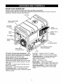
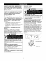
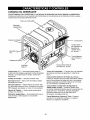
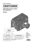
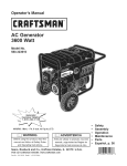
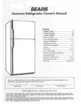
KNOW YOUR GENERATOR
Read the owner's manual and safety rules before operating your generator.
Compare the illustrations with your generator to familiarize yourself with the locations of various controls and
adjustments. Save this manual for future reference.
FuelTank
Spark Arrester Muffler
(not shown)
_
Fuel Valve
(not shown)
Circuit
Breakers (AC)
Choke
Lever
120/240 Volt AC,
30 Amp
Receptacle
Air Cleaner
Recoil Handle
Starter
Grounding Fastener
(2) 120 Volt AC, 20 Amp
Duplex Receptacles
Rocker Switch
(on engine shroud)
Oil Fill
120 Volt AC, 20 Amp, Duplex Receptacles i May
be used to supply electrical power for the operation of
120 Volt AC, 20 Amp, single phase, 60 Hz electrical,
lighting, appliance, tool and motor loads.
120/240 Volt AC, 30 Amp Locking Receptacle -May be used to supply electrical power for the
operation of 120 and/or 240 Volt AC, 30 Amp, single
phase, 60 Hz electrical, lighting, appliance, tool and
motor loads.
Air Cleaner -- Protects engine by filtering dust and
debris out of intake air.
Choke Lever i Used when starting a cold engine.
Circuit Breakers (AC) -- Push to reset circuit
breakers are provided to protect the generator against
electrical overload.
Fuel Tank i
Capacity of five (5) U.S. gallons.
Fuel Valve -- Used to turn fuel on and off to engine.
Grounding Fastener i If required, please consult a
qualified electrician, electrical inspector, or local
agency having jurisdiction.
Oil Fill -- Add engine oil here.
Recoil starter -- Used to start the engine.
Rocker Switch -- Set this switch to "On" before using
recoil starter. Set switch to "Off" to switch off engine.
Spark Arrestar Muffler i Exhaust muffler lowers
engine noise and is equipped with a spark arrester
screen.
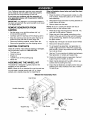
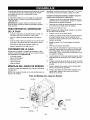
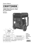
YourCraftsman
generatorrequiressomeassembly
andis readyfor useonlyafterit hasbeenproperly
servicedwiththe recommended
oilandfuel,
Refer to illustration shown below and install the wheel
kit as follows:
1.
Place the bottom of the generator cradle on a flat,
even surface. Temporarily place unit on blocks to
ease assembly.
2.
Slide axle through both axle mounting brackets on
cradle frame, as shown.
3.
Slide a wheel over the axle.
If you have any problems with the assembly of
your generator, please call the generator helpline
at 1-800-222-3136.
IMPORTANT: Any attempt to run the engine before it
has been serviced with the recommended oil will result
in an engine failure.
NOTE: Be sure to install both wheels with the air
pressure valve on the outboard side.
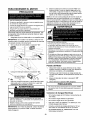
REMOVE GENERATOR FROM
CARTON
•
•
•
Set the carton on a rigid flat surface with "up"
arrows pointing upward.
Carefully open the top flaps of the shipping carton.
Place the e-ring onto the groove in the axle. You
may add the flat washer if desired.
5.
Place one end of the needle nose pliers on the
bottom of the axle and the other end of the pliers
on top of the e-ring. Seat the e-ring by pressing
the pliers closed.
6.
Repeat step 3 through 5 to secure second wheel.
7.
Remove the temporary blocks.
8.
To aid support leg assembly, rest generator on
cradle, engine end down. Attach the support leg
with two M8 x 16mm cap screws and two locking
hex nuts as shown.
9.
Use two 13 mm wrenches to tighten leg hardware.
Rest generator on wheels and support leg.
Slice two corners at one end of carton from top to
bottom and lay that side of carton down flat.
Remove all packing material, carton fillers, etc.
Remove the generator from the shipping carton.
CARTON
CONTENTS
Check all contents. If any parts are missing or damaged,
call the generator helpline at 1-800-222-3136.
• The main unit
• Owner's manual
•
4.
Engine oil
120/240 Volt, 30 Amp locking plug
Wheel Kit
ASSEMBLING
10. Center the handle bracket on generator frame at
support leg end of cradle, as shown.
11. Attach handle bracket with two M8 x 45mm cap
screws and two locking hex nuts.
THE WHEEL KIT
The wheel kit is designed to greatly improve the
portability of your generator.
NOTE: Wheel kit is not intended for over-the-road use.
You will need a socket wrench with 1/2" or 13ram
sockets and a needle-nose plier to install this kit.
Wheel
12. Check that all fasteners are tight and the tires are
inflated to the value marked on the tire or within
15 and 40 psi,
Kit Assembly
View
Cap Screw
\
Handle Assembly \
Flat Washer
/
Axle
Support Leg
Cap Screw
Wheel
Hex Nut _
E-Ring
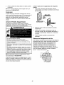
BEFORE STARTING
GENERATOR
THE
Add Fuel
WARNING
To operate the generator you will need to first add
engine oil and gasoline, as follows:
Engine
Add
Oil
NOTE: When adding oil to the engine crankcase, use
only high quality detergent oil rated with API service
classification SF, SG, SH, SJ or higher. DO NOT use
special additives.
1. Choose a viscosity according to the table below:
WHEN ADDING FUEL
Turn generator OFF and let it cool at least 2 minutes
before removing fuel cap. Loosen cap slowly to relieve
pressure in tank.
Fill fuel tank outdoors.
DO NOT overfill tank. Allow space for fuel expansion.
Keep fuel away from sparks, open flames, pilot lights,
heat, and other ignition sources.
DO NOT light a cigarette or smoke.
"_
_F
c
.20
._1
STARTING
L
0
.2b n
TEMPERATURE
L
2O
.i1o '
RANGE
J
32
_
1
4O
J
¢_0
i'o
ANTICIPATED
8O
2b
BEFORE
100
_b
NEXT
' 4'o
OIL CHANGE
NOTE: Synthetic oil meeting ILSAC GF-2, API
certification mark and API service symbol with "SJ/CF
ENERGY CONSERVING" or higher, is an acceptable
oil at all temperatures. Use of synthetic oil does not
alter required oil change intervals.
* The use of multi-viscosity oils (5W-30, 10W-30, etc.)
in temperatures above 40°F (4°C) will result in higher
than normal oil consumption. When using a multiviscosity oil, check oil more frequently.
** If using SAE 30 oil in temperatures below 40°F
(4°C), it will result in hard starting and possible engine
bore damage due to inadequate lubrication.
2. Place generator on a level surface.
3.
Clean area around yellow oil fill cap. Remove oil
fill cap.
4.
Slowly fill engine with oil through oil fill opening
until oil level is to the point of overflowing,
5.
6.
Install yellow oil fill cap and finger tighten securely.
Check engine oil level before starting each time
thereafter. If oil level is below the point of
overflowing, fill to proper level.
NOTE: Check oil often during engine break-in.
NOTE: This gasoline engine is certified to operate on
gasoline. Exhaust Emission Control System: EM
(Engine Modifications).
1. Use clean, fresh, regular UNLEADED fuel with a
minimum of 85 octane with equipment. DO NOT
use fuel which contains Methanol. DO NOT mix oil
with fuel.
2.
3.
Clean area around fuel fill cap, remove cap.
Slowly add regular unleaded fuel to fuel tank. Be
careful not to overfill. Allow about 1.5" of tank
space for fuel expansion, as shown here.
YNNNNN_NNNNNNN_
4.
Install fuel cap and wipe up any spilled fuel.
CAUTION! Alcohol-blended fuels (called gasohol,
ethanol or methanol) can attract moisture, which leads
to separation and formation of acids during storage.
Acidic gas can damage the fuel system of an engine
while in storage.
To avoid engine problems, the fuel system should be
emptied before storage of 30 days or longer. Drain the
fuel tank, start the engine and let it run until the fuel lines
and carburetor are empty. Use fresh fuel next season.
See "Storage" on page 16 for additional information.
NEVER use engine or carburetor cleaner products in
the fuel tank as permanent damage may occur.
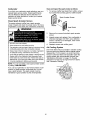
HOW TO USE YOUR GENERATOR
Generator
If you have any problems operating your generator,
please call the generator helpline at 1-800-222-3136,
Generator Clearance
System
ILWARNING
Ground
The generator has a system ground that connects the
generator frame components to the ground terminals
on the AC output receptacles. The system ground is
connected to the AC neutral wire (the neutral is
bonded to the generator frame).
Special Requirements
There may be Federal or State Occupational Safety
and Health Administration (OSHA) regulations, local
codes, or ordinances that apply to the intended use of
the generator. Please consult a qualified electrician,
electrical inspector, or the local agency having
jurisdiction.
In some areas, generators are required to be
registered with local utility companies.
If the generator is used at a construction site, there
may be additional regulations which must be
observed.
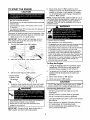
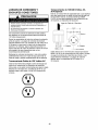
Connecting
System
to a Building's
Location
Electrical
Connections for standby power to a building's
electrical system must be made by a qualified
electrician. The connection must isolate the generator
power from utility power, and must comply with all
applicable laws and electrical codes.
Operate generator ONLY outdoors.
Keep exhaust gas from entering a confined area through
windows, doors, ventilation intakes or other openings.
DO NOT operate generator inside any building or
enclosure, including the generator compartment of a
recreational vehicle (RV).
The generator must be at least 5 ft. (152 cm) from
structures having combustible walls and/or other
combustible materials. Leave at least 3 ft. (92 cm) all
around generator including overhead, for adequate
cooling, maintenance and servicing.
Place generator in a well ventilated area, which will
allow for removal of deadly exhaust gas. DO NOT
place generator where exhaust gas could accumulate
and enter inside or be drawn into a potentially
occupied building. Ensure exhaust gas is kept away
from any windows, doors, ventilation intakes or other
openings that can allow exhaust gas to collect in a
confined area. Prevailing winds and air currents
should be taken into consideration when positioning
generator.
/
/
When using generator for backup power, notify utility
company. Use approved transfer equipment to isolate
generator from electric utility.
Use a ground circuit fault interrupter (GFCI) in any damp
or highly conductive area, such as metal decking or steel
work.
Typical Generator
Shown
DO NOT touch bare wires or receptacles.
DO NOT use generator with electrical cords which are
worn, frayed, bare or otherwise damaged.
DO NOT operate generator in the rain.
DO NOT handle generator or electrical cords while
standing in water, while barefoot, or while hands or feet
are wet.
DO NOT allow unqualified persons or children to operate
or service generator.
Exhaust Port
TO START THE ENGINE
CAUTION
6.
See "Don't Overload Generator".
Start generator and let engine stabilize before connectin£
electrical loads.
Move choke lever to "Run" position a short
distance at a time over several seconds in warm
weather or minutes in cold weather. Let engine
run smoothly before each change. Operate with
choke in "Run" position.
NOTE: If engine starts after 3 pulls but fails to run, or
if unit shuts down during operation, make sure unit is
on a level surface and check for proper oil level in
crankcase. This unit may be equipped with a low oil
3rotection device.
Connect electrical loads in OFF position, then turn ON
for operation.
Turn electrical loads OFF and disconnect from generator
before stopping generator.
, WARNING
Disconnect all electrical loads from the generator. Use
the following start instruction steps by numerical order:
1. Make sure unit is on a level surface.
IMPORTANT: Failure to start and operate unit on a
level surface will cause the unit not to start or shut
down during operation.
2. Turn the fuel valve to the "On" position.
DO NOT touch hot surfaces.
Allow equipment to cool before touching.
The generator must be at least 5 feet from structures having
combustible walls and/or other combustible materials.
J
_n
3.
Keep at least 3 feet of clearance on all sides of generator
for adequate cooling, maintenance and servicing.
In the State of California a spark arrester is required by
law (Section 4442 of the California Public Resources
Code). Other states may have similar laws. Federal laws
apply on federal lands. If you equip the muffler with a
spark arrester, it must be maintained in effective working
order.You can order a spark arrester through your
authorized Sears service dealer.
"(_n'_
Place the choke lever in the "Choke" position.
To Stop the Engine
4.
Unplug all electrical loads from generator panel
receptacles. NEVER start or stop engine with
electrical devices plugged in and turned on.
2.
Let engine run at no-load for several minutes to
stabilize internal temperatures of engine and
generator.
3.
Move rocker switch to "Off" position.
4.
Move fuel valve to "Off' position.
Set the rocker switch to "On" position.
.. Rocker Switch
is shown in the
On position
5.
1.
Grasp the recoil handle and pull slowly until slight
resistance is felt. Then pull rapidly to start engine.
WARNING
DO NOT stop engine by moving choke lever to "Choke"
CAUTION
position. Backfire, fire or engine damage could occur.
Connecting
Electrical
Loads
DO NOT connect 240 Volt loads to 120 Volt
receptacles.
DO NOT connect 3-phase loads to generator.
DO NOT connect 50 Hz loads to generator.
When starting engine, pull cord slowly until resistance is
felt and then pull rapidly to avoid kickback.
NEVER start or stop engine with electrical devices
plugged in and turned on.
IMPORTANT: If engine floods, place choke ]ever in
"Run" position and crank until engine starts.
Let engine stabilize and warm up for a few minutes
after starting.
Plug in and turn on desired 120 and/or 240 Volt
AC, single phase, 60 Hz electrical loads.
DO NOT OVERLOAD THE GENERATOR. See
"Don't Overload Generator".
I
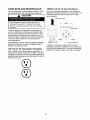
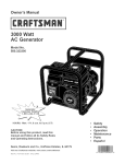
CORD SETS AND RECEPTACLES
120/240
Use only high quality, well-insulated, extension cords
with the generator's 120 Volt electrical receptacles.
This is a full capacity receptacle; it can supply the
generator's full rated output from this sole outlet, The
outlet is protected by two 20 Amp push-to-reset
circuit breakers.
CAUTION
Volt AC, 30 Amp Receptacle
4-Wire Cord Set
NEVER attempt to power a device requiring more
amperage than generator or receptacle can supply.
DO NOT overload the generator. See "Don't Overload
Generator".
fW
Check the ratings of all extension cords before you
use them, Extension cord sets used should be rated
for 125 Volt AC loads at 20 Amps or greater for most
electrical devices, Some devices, however, may not
require this type of extension cord. Check the owner's
manuals of those devices for the manufacturer's
recommendations.
Y (Hot)
NEMA L14-30
Keep extension cords as short as possible, preferably
less than 15 feet long, to prevent voltage drop and
possible overheating of wires.
120 Volt
AC, 20 Amp Duplex
(Neutral)
X (Hot)
Ground (Green)
A NEMA L14-30 plug is used with this 240 Volt
receptacle, Connect a suitable 4-wire cord set to the
plug and to the desired load. The cord set should be
rated for 250 Volt AC loads at 30 Amps (or greater).
Receptacle
Each receptacle is protected against overload by a
single 20 Amp push-to-reset circuit breaker, Use each
receptacle to operate 120 Volt AC, single phase 60 Hz
electrical loads requiring up to 2,400 watts (2.4 kW) at
20 Amps of current,
10
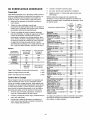
DON'T OVERLOAD
GENERATOR
Capacity
You must make sure your generator can supply
enough rated (running) and surge (starting) watts for
the items you will power at the same time. Follow
these simple steps:
1. Select the items you will power at the same time.
2.
3.
Refrigerator
Deep Freezer
Television
Light (75 Watts)
800
500
500
75
3075 Total
Running Watts
1800 Highest
Sure Watts
Highest Additional Surge Watts
= 1800
Total Generator Output Required
= 4875
Power
Security System
AM/FM Clock Radio
Garage Door Opener- 1/2 HP
Electric Water Heater - 40
Gallon
DIY/Job Site
Quartz Halogen Work Light
Airless Sprayer - 1/3 HP
Reciprocating Saw
Electric Drill - 1/2 HP
Circular Saw - 7 1/4"
Miter Saw - 10"
Table Planer - 6 °
Table Saw/Radial Arm Saw 10"
Air Compressor - 1-1/2 HP
Management
To prolong the life of your generator and attached
devices, it is important to take care when adding
electrical loads to your generator. There should be
nothing connected to the generator outlets before
starting it's engine. The correct and safe way to
manage generator power is to sequentially add loads
as follows:
1.
With nothing connected to the generator, start the
engine as described in this manual.
2.
Plug in and turn on the first load, preferably the
largest load you have.
3.
Permit the generator output to stabilize (engine
runs smoothly and attached device operates
properly.
Repeat steps 4 and 5 for each additional load.
Electric Stove - Single Element
Hot Plate
Family Room
DVD/CD Player
VCR
Stereo Receiver
Color Television - 2T'
Personal Computer w/17 °
monitor
Other
1600
500
= 3075
6.
Light Bulb - 75 watt
Deep Freezer
Sump Pump
Refrigerator/Freezer18 Cu. Ft.
Water Well Pump - 1/3 HP
Heating/Cooling
Window AC - 1O_OOOBTU
Window Fan
Furnace Fan Blower - 1/2 HP
Kitchen
Microwave Oven - 1006 Watt
Coffee Maker
Additional Surge
(Starting) Watts
1600
Total Rated (Running) Watts
Again, permit the generator to stabilize.
Rated*
(Running)
Watts
Additional
Surge
(Starting)
Watts
Essentials
Example:
Window Air
Conditioner
5.
Tool or Appliance
Estimate how many surge (starting) watts you will
need. Surge wattage is the short burst of power
needed to start electric motor-driven tools or
appliances such as a circular saw or refrigerator.
Because not all motors start at the same time,
total surge watts can be estimated by adding only
the item(s) with the highest additional surge watts
to the total rated watts from step 2.
Ra_d
(Running)Watts
1200
Plug in and turn on the next load.
NEVER add more loads than the generator capacity.
Take special care to consider surge loads in generator
capacity, as described above.
Total the rated (running) watts of these items. This
is the amount of power your generator must
produce to keep your items running. See the table
on the right.
Tool or Appliance
4.
*Wattages
appliance
11
listed are approximate
for actual wattage.
75
500
860
860
1006
500
1200
1600
2000
1206
300
860
1800
600
1300
1006
1506
1506
2506
100
100
45O
5OO
8OO
180
3OO
480
4006
526
1006
660
960
1006
1506
1806
1806
2006
1200
966
1000
1500
1800
1800
2000
2506
only.
2500
Check
tool or
ENGINE TECHNICAL
INFORMATION
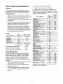
PRODUCT
This is a single cylinder, overhead valve(OHV), air
cooled engine. It is a low emissions engine.
Generator
Specifications
Rated Maximum Power .........
Surge Power .................
Rated AC Voltage ...................
Rated Maximum AC Current
at 240 Volts .....................
at 120 Volts .....................
Rated Frequency ...............
Phase .............................
Unit Weight .............................
In the State of California, Model Series 200000
engines are certified by the California Air Resources
Board to meet emissions standards for 250 hours.
Such certification does not grant the purchaser, owner
or operator of this engine any additional warranties
with respect to the performance or operational life of
this engine. The engine is warranted solely according
to the product and emmisions warranties stated
elsewhere in this manual.
Power
SPECIFICATIONS
5600 Watts (5.6 kW)
8600 Watts (8.6 kW)
120/240 Volts
23.3 Amperes
46.6 Amperes
60 Hz at 3600 rpm
Single Phase
170 Ibs.
Engine Specifications
Ratings
Rated Horsepower .................
10 at 3600 rpm
Bore ............................
3.12 in. (79mm)
Stroke ..........................
2.44 in. (62mm)
Displacement ...................
18.64 in. (305 cc)
Spark Plug
Type: ..........
Champion RC12YC or Equivalent
Set Gap To: ................
0.030inch (0.76mm)
Armature Air Gap: ..................
0.008-0.012 in.
(0.20-0.30mm)
Valve clearance with valve springs installedand piston1/4 in.
(6 mm) past top dead center (check when engine iscold).
Intake ...........................
0.004-0.006 in.
(0.10-0.15 mm)
Exhaust ..........................
0.004-0.006 in.
The power ratings for an individual engine model are
initially developed by starting with SAE (Society of
Automotive Engineers) code J1940 (Small Engine
Power & Torque Rating Procedure) (Revision 200205). Given both the wide array of products on which
our engines are placed, and the variety of
environmental issues applicable to operating the
equipement, it may be that the engine you have
purchased will not develop the rated horsepower when
used in a peice of power equipment (actual "on-site"
power). This difference is due to a variety of factors
including, but not limited to, the following: differences
in altitude, temperature, barometric pressure, humidity,
fuel, engine lubrication, maximum governed engine
speed, individual engine to engine variability, design of
the particular peice of power equipment, the manner in
which the engine is operated, engine run-in to reduce
friction and clean out of combustion chambers,
adjustments to the valves and carburetor, and other
factors. The power ratings may also be adjusted
based on comparisons to other similar engines
utilizedin similar applications, and will thereforenot
necessarily match the values derived using the
foregoing codes.
(0.10-0.15 mm)
5 U.S. gallons
Fuel Capacity ......................
Oil Capacity ................
28 Ounces (.8 Liters)
Oil Type:
Above 40 ° F ........................
Below 40 ° F ............
12
Sae 30
SAE 5W-30 or 10W-30
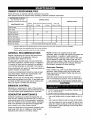
OWNER'S
RESPONSIBILITIES
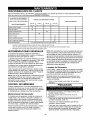
Follow the hourly or calendar intervals, whichever occurs first,
More frequent service is recuired when operating in adverse conditions noted below.
MAINTENANCE
FILL
SCHEDULE
IN DATES
COMPLETE
AS YOU
REGULAR
MAINTENANCE
SERVICE
DATES
SERVICE
TASK
SERVICE DATES
Before
Each
Every
Use
Check oil level
X
Clean debris
X
25 HOURS
Every
or Yearly
50 HouRS
or Yearly
Change engine oil
Every
100
Hours or Yearly
X _
Service air cleaner
X 2
X
Service spark plug
Service spark arrester
X
Clean cooling system
X2
If unit is to remain idle for longer than 30 days
Prepare for storage
Change oil after the fiRSt (5) operating hours and every 50 hours or every year, whichever
Change sooner when operating
2
occurs first, thereafter
under dirty or dusty conditions.
Clean or replace more often under dirty or dusty conditions
GENERAL
RECOMMENDATIONS
NOTE: DO NOT use a garden hose to clean
generator. Water can enter the engine fuel system and
cause problems. In addition, if water enters the
generator through cooling air slots, some of the water
will be retained in voids and cracks of the rotor and
stator winding insulation. Water and dirt buildup on the
generator internal windings will eventually decrease
the insulation resistance of these windings.
Regular maintenance will improve the performance
and extend the life of the generator. See any
authorized Sears dealer for service.
The generator's warranty does not cover items that
have been subjected to operator abuse or negligence.
To receive full value from the warranty, the operator
must maintain generator as instructed in this manual.
Generator
Some adjustments will need to be made periodically to
properly maintain your generator.
Daily or before use, clean accumulated debris from
generator. Keep linkage, spring and controls clean.
Keep area around and behind muffler free from any
combustible debris.
All service and adjustments should be made at least
once each season. Follow the requirements in the
"Maintenance Schedule" chart above.
Generator parts should be kept clean to reduce the
risk of overheating and ignition of accumulated debris.
NOTE: Once a year you should clean or replace the
spark plug and replace the air filter. A new spark plug
and clean air filter assure proper fuel-air mixture and
help your engine run better and last longer.
EMISSION
Cleaning
Use a damp cloth to wipe exterior surfaces clean.
CAUTION
CONTROL
Maintenance, replacement or repair of the emission
control devices and systems may be performed by any
non-road engine repair establishment or individual.
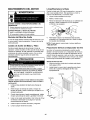
GENERATOR
DO NOT expose generator to excessive moisture, dust,
dirt, or corrosive vapors.
DO NOT insert any objects through cooling slots.
MAINTENANCE
Use a soft bristle brush to loosen caked on dirt, oil,
etc.
Generator maintenance consists of keeping the unit
clean and dry. Operate and store the unit in a clean dry
environment where it will not be exposed to excessive
dust, dirt, moisture or any corrosive vapors. Cooling air
slots in the generator must not become clogged with
snow, leaves, or any other foreign material.
Use a vacuum cleaner to pick up loose dirt and debris.
Use low pressure air (not to exceed 25 psi) to blow
away dirt. Inspect cooling air slots and openings on
the generator. These openings must be kept clean
and unobstructed.
Check the cleanliness of the generator frequently and
clean when dust, dirt, oil, moisture or other foreign
substances are visible on its exterior surface.
13
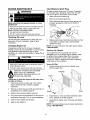
ENGINE MAINTENANCE
Clean/Replace
Plug
Change the spark plug every 100 hours of operation
or once each year, whichever comes first, This will
help your engine to start easier and run better.
1. Clean area around spark plug.
WARNING
WHEN ADJUSTING
_,ENERATOR
Spark
2.
Remove and inspect spark plug.
3.
Check electrode gap with wire feeler gauge and
set spark plug gap to 0.030 inch (0.76mm) if
OR MAKING REPAIRS TO YOUR
necessa_.
Disconnect the spark plug wire from the spark plug and
place the wire where it cannot contact spark plug.
VNEN TESTING FOR ENGINE SPARK
Use approved spark plug tester.
\
DO NOT check for spark with spark plug removed.
Checking
Oil Level
Oil level should be checked prior to each use or at
least every 5 hours of operation. Keep oil level
maintained.
4.
Changing
NOTE: You can purchase a new spark plug by calling
1-800-366-PART.
Engine Oil
Change the oil after the first 5 hours of operation.
Change oil every 50 hours thereafter. If you are using
your generator under extremely dirty or dusty
conditions, or in extremely hot weather, change the oil
more often.
Replace spark plug if electrodes are pitted, burned
or porcelain is cracked. Use a recommended
replacement plug.
Service
Air Cleaner
Your engine will not run properly and may be
damaged if you run it using a dirty air cleaner. Clean
or replace the air cleaner paper filter once every
25 hours of operation or once a year, whichever
comes first. Clean or replace more often if operating
under dusty or dirty conditions.
CAUTION
Service Air Filter
1. Loosen screws and remove air cleaner cover.
Remove paper filter.
Used motor oil has been shown to cause skin cancer in
certain laboratory animals.
Thoroughly wash exposed areas with soap and water.
Cartridge
DON'T POLLUTE. CONSERVE
RESOURCES. RETURN USED OIL TO
KEEP OUT OF CENTERS.
REACH OF CHILDREN.
COLLECTION
Cover
Change the oil while the engine is still warm from
running, as follows:
1. Clean area around oil drain plug. The oil drain
plug is located at base of engine, opposite
carburetor.
2,
Remove oil drain plug and oil fill cap and drain oil
completely into a suitable container.
3.
Install oil drain plug and tighten securely.
4.
Fill oil sump with recommended oil to the point of
overflowing. See page 7 for oil recommendations.
2.
Install clean (or new) air cleaner assembly inside
cover. Dispose of old filter properly,
5.
Install oil cap. Tighten cap securely.
3.
6.
Wipe up any spilled oil.
Assemble air cleaner cover onto base and tighten
screws.
Screw.
Base
NOTE: You can purchase new air cleaner elements by
calling 1-800-366-PART.
14
Carburetor
Clean and inspect the spark arrester as follows:
1. To remove muffler heat shield from muffler, remove
four screws that connect guard to muffler bracket,
If you think your carburetor needs adjusting, see your
nearest Sears service center, Engine performance
may be affected at altitudes above 3000 feet, For
operation at higher elevations, contact your nearest
Sears service center,
Clean
Spark
Arrester
Spark Arrester Screen
Screen
The engine exhaust muffler has a spark arrester
screen, Inspect and clean the screen every 100 hours
of operation or once each year, whichever comes first,
Muffler
Heat Shield
WARNING
DO NOT touch hot surfaces.
Allow equipment to cool before touching.
2.
Remove four screws that attach spark arrester
screen,
3.
Inspect screen and replace if torn, perforated or
otherwise damaged, DO NOT use a defective
screen, If screen is not damaged, clean it with
commercial solvent,
4.
Reattach screen and muffler guard.
Air Cooling
The generator must be at least 5 feet from structures having
combustible walls and/or other combustible materials.
System
Over time debris may accumulate in cylinder cooling
fins and cannot be observed without partial engine
disassembly, For this reason, we recommend you
have an authorized Sears service dealer clean the
cooling system per recommended intervals (see
"Maintenance Schedule" on page 13), Equally
important is to keep top of engine free from debris,
See "Generator Cleaning".
Keep at least 3 feet of clearance on all sides of generator
for adequate cooling, maintenance and servicing.
In the State of California a spark arrester is required by law
(Section 4442 of the California Public Resources Code).
Other states may have similar laws. Federal laws apply on
federal lands. If you equip the muffler with a spark arrester,
it must be maintained in effective working order.
CLEAN
NOTE: You can purchase a new spark arrester screen
by calling 1-800-366-PART.
If you use your generator on any forest-covered, brushcovered, or grass-covered unimproved land, it must
have a spark arrester. The spark arrester must be
maintained in good condition by the owner/operator.
15
GENERAL
Change Oil
The generator should be started at least once every
seven days and allowed to run at least 30 minutes. If
this cannot be done and you must store the unit for
more than 30 days, use the following information as a
guide to prepare it for storage.
While engine is still warm, drain oil from crankcase.
Refill with recommended grade.
Long Term Storage
Oil Cylinder Bore
Remove spark plug and pour about 1 ounce (30ml)
of clean engine oil into the cylinder.
Instructions
Install spark plug and crank slowly to distribute oil.
It is important to prevent gum deposits from forming in
essential fuel system parts, such as the carburetor,
fuel filter, fuel hose or tank during storage. Also,
experience indicates that alcohol-blended fuels (called
gasohol, ethanol or methanol) can attract moisture,
which leads to separation and formation of acids
during storage. Acidic fuel can damage the fuel
system of an engine while in storage.
To avoid engine problems, the fuel system should be
emptied before storage of 30 days or longer. Follow
these instructions:
Generator
WARNING
1.
Clean generator as outlined in "Generator Cleaning".
2.
Check that cooling air slots and openings on
generator are open and unobstructed.
Other Storage
Tips
1. DO NOT store fuel from one season to another,
WHEN STORING FUEL OR EQUIPMENT WITH FUEL IN
TANK
Store away from furnaces, stoves, water heaters, clothes
dryers or other appliances that have pilot light or other
ignition source because they can ignite fuel vapors.
VHEN DRAINING FUEL
Turn generator OFF and let it cool at least 2 minutes
before removing fuel cap. Loosen cap slowly to relieve
pressure in tank.
Drain fuel tank outdoors.
DO NOT light a cigarette or smoke.
2.
Run engine until engine stops from lack of fuel.
3.
If possible, store unit indoors and cover it to give
protection from dust and dirt. BE SURE TO
EMPTY FUEL TANK,
4.
Cover unit with a suitable protective cover that
does not retain moisture.
5.
Store generator in clean, dry area.
DO NOT place a storage cover over a hot generator.
Let equipment cool for a sufficient time before placing
the cover on the equipment.
Protect Fuel System
Remove all gasoline from fuel tank to prevent gum
deposits from forming on these parts and causing
possible malfunction of engine.
Replace fuel can if it starts to rust. Contaminated
fuel will cause engine problems.
WARNING
Keep fuel away from sparks, open flames, pilot lights,
heat, and other ignition sources.
1.
2.
16
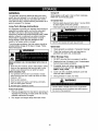
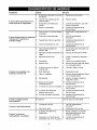
Problem
Cause
Correction
1,
1,
Reset circuit breaker,
One of the circuit breakers is
open,
Engine is running, but no AC
output is available.
2,
Poor connection or defective
cord set,
2,
Check and repair,
3,
Connected device is bad.
3,
Connect another device that is
in good condition.
Engine runs good at no-load but
"bogs down" when loads are
connected,
4.
Fault in generator,
4,
Contact Sears service facility.
1.
Short circuit in a connected
load,
1,
Disconnect shorted electrical
load.
2.
Generator is overloaded,
2,
See "Don't Overload
Generator",
3.
Engine speed is too slow.
3,
Contact Sears service facility.
4.
Shorted generator circuit,
4,
Contact Sears service facility.
1.
Fuel valve in the "Off' position.
1,
Set fuel valve to the "On"
position.
Engine will not start; or starts
and runs rough.
Engine shuts down during
operation.
2.
Rocker Switch set to "Off'.
2,
Set switch to "On",
3,
Dirty air cleaner.
3,
Clean or replace air,
4,
Out of gasoline.
4,
Fill fuel tank,
5,
Stale gasoline,
5,
Drain fuel tank; fill with fresh
fuel,
6,
Spark plug wire not connected
to spark plug,
6,
Connect wire to spark plug,
7,
Bad spark plug,
7,
Replace spark plug,
8.
Water in gasoline,
8,
Drain fuel tank; fill with fresh
fuel,
9.
Overchoking,
9,
Open choke fully and crank
engine,
10, Low oil level.
10, Fill crankcase to proper level.
11, Excessively rich fuel mixture,
11, Contact Sears service facility.
12, Intake valve stuck open or
closed,
12. Contact Sears service facility.
13, Engine has lost compression,
13, Contact Sears service facility,
Out of gasoline,
Fill fuel tank.
1,
Load is too high,
1,
2,
Dirty air filter,
2,
Replace air filter,
1,
Choke is opened too soon,
1,
Move choke to halfway position
until engine runs smoothly.
2,
Carburetor is running too rich or 2,
too lean,
Engine lacks power.
Engine "hunts"
or falters.
17
See "Don't Overload
Generator",
Contact Sears service facility.
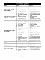
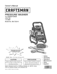
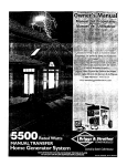
CRAFTSMAN
5600 Watt AC Generator
580.325600
BRIDGE
RECTIFIER
BLUE
(2)
RED (6)
(4)
(1)
EXCITATIDN
FIELD
BLUE
RED
BLUE
(ii)
RED
(22)
BLACK
GRAY
BLACK
(33)
GRAY
(44)
(22)
GRAY
(44A)
120V/20A
BLUE
(IIA)
RED
(22)
(O)
BLUE
(IIA)
REB
(22)
BLUF
(IIA)
120/240V/30A
BLUE
(IIA)
(22)
18
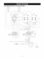
CRAFTSMAN
CIRCUIT
BREAKER
2
5600 Watt AC Generator
580.325600
CIRCUIT
BREAKER
1
2
IIA
IIA
120/240V
30A
IIA
4,
120V
20A
120V
20A
IIA
I
22
/
22
IIA
IIA
33
22
ii
_/ARNING!
TAB
22
MUST
NOT
BROKEN
BLACK
(33)
SIX LUG
CONNECTOR
HOUSING
NOTE=
BE
POSITIVE
BRUSH
13 CLOSEST
TO
BEARING
REB
(61
/2/
CUSTONER
GROUND
LUG
19
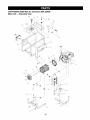
CRAFTSMAN
Main Unit --
5600 Watt AC Generator
Exploded
580.325600
View
45
52
\\
51
>-40
35
50
44
'\
\
\
41
900
\
\
@
4
37
6
10
14
8
11
\
54
\
\
26
'\
\
\
25
¢8
22
2
31
2O
CRAFTSMAN
Main Unit-
5600 Watt AC Generator
Parts List
580.325600
Item
1
2
4
5
6
8
10
11
14
15
17
18
19
20
21
22
23
24
25
26
31
34
35
37
40
41
44
45
48
50
51
52
55
58
59
900
Part #
M194766GS
194150GS
190220GS
NSP
194151GS
96796GS
190274BGS
187365FGS
194729GS
695398
189008GS
60706GS
83083GS
B4986GS
194153GS
86494GS
86292GS
192794GS
191190GS
74908GS
77816GS
195422GS
194397GS
192376GS
194398GS
192980GS
193668GS
B4363GS
195373GS
188333GS
194799GS
189235GS
73054GS
190355GS
NSP
Description
CRADLE
KIT, Vibration Mount, 45 ° Srv
HOUSING, Engine Adapter
ASSY, Alternator (see page 24)
KIT, Hardware Mount, Aptr.
WASHER, M8 Flat
SBHCS, 3/8-16 x 1.0 Lg.
HHCS, 5/16-24 x 7.44
KIT, Muffler Bracket, w/Hardware
GASKET, Exhaust
MUFFLER
SCREW, 5/16 - 18 x 3/4"
SCREEN, Spark Arrest
DECAL, Ground, Green
KIT, Mount, Vibration. AIt. Srv
SCREW, Wing M6 - 1.0 x 16
SCREW, 10 - 16 x 3/4, Self Driller
SHIELD, Heat
CAP
SCREW, M5-0.8 x 10 Taptite
DECAL, Hot Muffler
COVER, Bearing Carrier
KIT, Fuel Hose, Formed, Srv
SCREW, 12-24 x 1/2 THD Forming
KIT, Hardware Fuel Tank
KIT, Valve, Tank, Srv
ASSY, Tank, Fuel (Includes Items 41, 50, 51 & 52)
CAP, Fuel Gauge
WIRE, Ground
DECAL, Gas Fill
DECAL, Danger
DECAL, Start Instructions
DECAL, Shut-Off, Fuel
ASSY, Control Panel (see page 22)
NUT, Palnut, 3/16"
ENGINE
Parts
Not Illustrated
191646GS
43438GS
AB3061GS
191559GS
DECAL, Set
PLUG, 250V, 30A
BOTTLE, Oil
MANUAL, Owners
Optional Accessories Not Shown
0932688GS
Cord Wrap Kit
9932785GS
Storage Cover
* - Items without part numbers are common fasteners, available at local hardware stores.
21
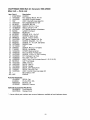
CRAFTSMAN
Control
5600 Watt AC Generator
Panel -- Exploded
580.325600
View and Parts List
16
15
\
\
\
\
7
6
\
\
\
\
\
\
\
\
\
13
17
\
\
m
14
9
s
11
10
2
Item
1
2
6
7
8
9
10
11
12
13
14
15
16
17
Part #
195112GS
188889GS
68759GS
84198GS
75207GS
43437GS
93857GS
188890GS
22694GS
Description
KIT, Control Panel Lid
CONTROL PANEL, Compact
OUTLET, 120V, 20A, Duplex
NUT, Palnut, Pushnut, 5/32
CAP, Circuit Breaker
BREAKER, Circuit
OUTLET, 120/240V, Locking, 30A
NUT, Palnut, Pushnut, 3/16
SCREW, Phillips, Head 3.5 x 18
BAR, Retaining
COVER, Back, Control Panel
SCREW, Self Tapping, STC 3 x 18
HOUSING, Receptacle
SCREW, Phillips, 3.5 x 14
* - Items without part numbers are common fasteners,
available at local hardware stores.
22
\
\,
12
CRAFTSMAN
5600 Watt AC Generator
Wheel Kit -- Exploded
580.325600
View and Parts List
\
\
l
3
8
/
%
/
7
Item
1
2
3
4
5
6
7
8
9
Part #
189715GS
B1764GS
52858GS
191267HGS
B4966GS
191265GS
Parts Not Illustrated
189718GS
189716GS
Description
ASSY, Handle
LEG, Mounting
NUT, Locking Hex M8- 1.25
HHCS, M8 - 1.25 x 45
AXLE, 5/8"x22.87"
WHEEL
E-RING
WASHER, Flat 5/8
HHCS, M8- 1.25 x 16
GRIP
CAP, Handle End
* - Items without part numbers are common fasteners,
available at local hardware stores.
23
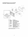
CRAFTSMAN
5600 Watt AC Generator
Alternator
Exploded
--
580.325600
View and Parts List
\
1
5
\
2
6
8
13
10
Item
1
2
3
4
5
6
7
8
9
10
13
Part#
186059GS
190032GS
190079AGS
186060GS
86308HGS
91825GS
66849GS
22694GS
81917GS
193428AGS
194274GS
Description
ADAPTER, Mounting, Alternator
ROTOR
STATOR
RBC, with O-Ring (p/n 189197GS)
HHCS, M6 - 1.0 x 140 SEMS
ASSY, Holder, RectifiedBrush
TAPTITE, M5 - 0.8 x 16
RECEPTACLE, 6 pin
PIN, Roll, 4ram x 10
ASSY, Wire, Ground
HARNESS, Wire, Power
24
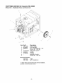
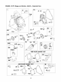
ENGINE,
10 HP, Briggs and Stratton,
204412
- Exploded
View
12
718A
22 _
28_
364
718 j
306
742
1052_
774_
356
799A_
cJ
15
615
307
493
27 o
105_
1095 VALVE GASKET SET
7
883
868
358 ENGINE GASKET SET
_o_ _>
8_
3o_
51A_
25
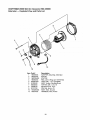
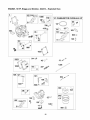
ENGINE,
10 HP, Briggs and Stratton,
204412
- Exploded
View
121 CARBURETOR OVERHAUL KIT
798_
11oo
633 @
105
868
914
633 @
633 ®
231
127 O
51A_
95
137
105_
117
950
369 _
26
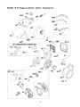
ENGINE,
10 HP, Briggs and Stratton,
204412
- Exploded
View
347
188_
356A_
356B
56__
505
564A
334
564%
977 CARBURETOR
GASKET SET
445
633@
1°7°_
1005
60_
455
456_
597D
J
689_
459_
_
_j
J
f
305
121(
1211
59_
55
65 _
27
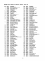
ENGINE,
Item
1
2
3
5
7
11
12
13
15
16
18
19
20
21
22
23
24
25
26
27
28
29
30
32
33
34
35
36
40
42
45
46
51
51A
53
55
58
59
60
65
95
97
98
104
105
106
117
118
121
122
125
127
130
133
135
137
141
146
161
163
185
188
192
209
10 HP, Briggs and Stratton,
Part #
695464
495657
391086
697233
694872
696796
694953
690360
691686
694678
694951
495657
391086
281658
695174
694954
222696
695457
695458
695459
695460
694004
694006
694006
694010
690975
696581
694691
694692
690976
499596
697464
694865
694865
690694
499586
690977
697239
694874
694875
694869
695288
693389
805957
715257
690837
691636
696387
695408
694918
696136
696209
696134
696135
696146
694876
695918
690727
696139
694914
696142
695426
696208
690979
694870
692277
690958
690877
690083
694867
204412
Description
Cylinder Assembly
Kit-Bushing/Seal (Magneto Side)
Seal-Oil (Magneto Side)
Head-Cylinder
Gasket-Cylinder Head
Tube-Breather
Gasket-Crankcase
Screw (Cylinder Head)
Plug-Oil Drain
Crankshaft
Cover-Crankcase
Kit-Bushing/Seal (PTO Side)
Seal-Oil (PTO Side)
Cap-Oil Fill
Screw (Engine Sump)
Flywheel
Key-Flywheel
Piston Assembly (Standard)
Piston Assembly (.010" Oversize)
Piston Assembly (.020" Oversize)
Piston Assembly (.030" Oversize)
Ring Set (Standard)
Ring Set (.010" Oversize)
Ring Set (.020" Oversize)
Ring Set (.030" Oversize)
Lock-Piston Pin
Pin-Piston
Rod-Connecting
Dipper-Connecting Rod
Screw (Connecting Rod)
Valve-Exhaust
Valve-Intake
Spring-Valve (Intake)
Spring-Valve (Exhaust)
Retainer-Valve
Keeper-Valve
Tappet-Valve
Camshaft
Gasket-Intake
Gasket-intake
Stud (Carburetor)
Housing-Rewind Starter
Rope-Starter (Cut to Required Length)
Grip-insert
Grip-Starter Rope
Screw (Rewind Starter)
Screw (Throttle Valve)
Shaft-Throttle
Kit-Idle Speed
Pin-Float Hinge
Valve-Float Needle
Valve-Choke
Jet-Main (Standard)
Jet-Main (High Altitude)
Kit-Carburetor Overhaul
Spacer-Carburetor
Carburetor
Plug-Welch
Valve-Throttle
Float-Carburetor
Tube-Fuel Transfer
Gasket-Float Bowl
Kit-Choke Shaft
Key-Timing
Base-Air Cleaner
Gasket-Air Cleaner
Nut (Air Cleaner Base)
Screw (Control Bracket)
Bali-Rocker Arm
Spring-Governor
- Parts List
Item
219
220
222
227
231
286
304
305
306
307
332
333
334
337
347
356
356A
356B
358
364
369
425
445
455
456
459
493
505
552
562
564
564A
592
597
604
606
615
616
632
633
635
689
718
718A
741
742
746
774
798
799
799A
868
883
914
950
966
975
977
1005
1022
1023
1026
1029
1052
1052A
1070
1095
1100
1210
1211
28
Part #
693578
691724
694866
694864
691636
695186
697250
690960
697204
691660
694685
715231
691061
491055
697854
695366
695295
692603
695438
695365
695422
694515
491588
694683
692299
281505
694861
691251
694674
92613
692577
692198
690800
691696
697236
695287
694676
694675
695917
690998
710901
691855
690959
695178
691288
692564
694679
695447
690967
690297
695446
690968
695398
693732
695407
692321
696138
696147
694684
690971
697691
695177
690972
694858
696954
691058
695440
690973
498144
498144
Description
Gear-Governor
Washer (Governor Gear)
Bracket-Control
Lever-Governor Control
Screw (Choke Valve)
Module-Oil Sensor
Housing-Blower
Screw (Blower Housing)
Shield-Cylinder
Screw (Cylinder Shield)
Nut (Flywheel)
Armature-Magneto
Screw (Magneto Armature)
Plug-Spark
Switch-Rocker
Wire-Stop
Wire-Stop
Wire-Stop
Gasket Set-Engine
Terminal-Oil Plug
Spring-Float Bowl
Screw (Air Cleaner Cover)
Filter-Air Cleaner Cartridge
Cup-Flywheel
Plate-Pawl Friction
PawI-Ratchet
Bracket-Mounting
Nut (Governor Control Lever)
Bushing-Governor Crank
Bolt (Governor Control Lever)
Screw (Control Cover)
Screw (Control Cover)
Nut (Rewind Starter)
Screw (Pawl Friction Plate)
Cover-Control
Starter-Rewind
Retainer-Governor Shaft
Crank-Governor
Spring/Link-Mechanical
Governor
Seal-Choke/Throttle Shaft
Boot-Spark Plug
Spring-Friction
Pin-Locating
Pin-Locating
Gear-Timing
Retainer-E Ring
Gear-Idler
Screw (Stop Wire)
Screw (Rocker Arm)
Screw (Oil Sensor)
Screw (Oil Sensor)
Seal-Valve
Gasket-Exhaust
Screw (Rocker Cover)
Screw (Float Bowl)
Cover-Air Cleaner
Bowl-Float
Gasket Set-Carburetor
Fan-Flywheel
Gasket-Rocker Cover
Cover-Rocker
Rod-Push
Rocker Arm
Sensor-Oil
Sensor-Oil
Screw (Flywheel Fan)
Valve Gasket Set
Pivot-Rocker Arm
Pulley/Spring Assembly (Pulley)
Pulley/Spring Assembly (Spring
29
Seam,
Roebuck and Co., U.S.A. (Sears), the California Air Resources
Board (CARB)
the United States Environmental
Protection Agency (U.S.EPA)
and
Emission Control System Warranty Statement
(Owner's Defect Warranty Rights and Obligations)
EMISSION CONTROL WARRANTY COVERAGE IS
a. Fuel Metering System
APPLICABLE TO CERTIFIED ENGINES PURCHASED IN
CALIFORNIA IN 1995 AND THEREAFTER WHICH ARE
USED IN CALIFORNIA, AND TO CERTIFIED MODEL
YEAR 1997 AND LATER ENGINES WHICH ARE
PURCHASED AND USED ELSEWHERE IN THE UNITED
STATES (AND AFTER JANUARY 1, 2001 IN CANADA).
Cold start enrichment system
Carburetor and internal parts
Fuel Pump
b. Air Induction System
Air cleaner
Intake manifold
c. Ignition System
Spark plug(s)
Magneto ignition system
d. Catalyst System
Catalytic converter
Exhaust manifold
Air injection system or pulse valve
e. Miscellaneous Items Used in Above Systems
Vacuum, temperature, position, time sensitive valves
and switches
Connectors and assemblies
Length of Coverage
Sears warrants to the initial owner and each subsequent
owner that the Warranted Parts shall be free from
defects in materials and workmanship which caused the
failure of the Warranted Parts for a period of two years
from the date the engine is delivered to a retail
purchaser.
No Charge
Repair or replacement of any Warranted Part will be
performed at no charge to the owner, including
diagnostic labor which leads to the determination that a
Warranted Part is defective, if the diagnostic work is
performed at an approved Sears Service Center.
Claims and Coverage Exclusions
Warranty claims shall be filed in accordance with the
provisions of the Sears Warranty Policy. Warranty
coverage shall be excluded for failures of Warranted
Parts which are not odginal Sears parts or because of
abuse, neglect or improper maintenance as set forth in
the Sears Engine Warranty Policy. Sears is not liable to
cover failures of Warranted Parts caused by the use of
add-on, non-original, or modified parts.
Maintenance
Any Warranted Part which is not scheduled for
replacement as required maintenance or which is
scheduled only for regular inspection to the effect of
"repair or replace as necessary" shall be warranted as to
defects for the warranty period. Any Warranted Part
which is scheduled for replacement as required
maintenance shall be warranted as to defects only for
the period of time up to the first scheduled replacement
for that part. Any replacement part that is equivalent in
performance and durability may be used in the
performance of any maintenance or repairs. The owner
is responsible for the performance of all required
maintenance, as defined in this owner's manual
Consequential
Coverage
Coverage hereunder shall extend to the failure of any
engine components caused by the failure of any
Warranty Part still under warranty.
California
and U.S. EPA Emission
Control Warranty
Statement
Your Warranty Rights and Obligations
The California Air Resources Board (CARB), U.S.EPA and
Sears are pleased to explain the Emission Control System
Warranty on your model year 2000 and later small off-road
engine (SORE). In California, new small off-road engines
must be designed, built and equipped to meet the State's
stringent anti-smog standards. Elsewhere in the United
States, new non-road, spark-ignition engines certified for
model year 1997 and later, must meet similar standards set
forth by the U.SEPA. Sears must warrant the emission
control system on your engine for the periods of time listed
below, provided there has been no abuse, neglect, or
improper maintenance of your small off-road engine.
Your emission control system may include parts such as the
carburetor or fuel-injection system, the ignition system, and
catalytic converter. Also included may be hoses, belts,
connectors and other emission related assemblies.
Where a warrantable condition exists, Sears will repair your
small off-road engine at no cost to you including diagnosis,
parts and labor.
2.
3.
Sears Emission
Control Defects Warranty
Coverage
The 1995 and later small off-road engines are warranted for
two years. If any emission-related part on your engine is
defective, the part will be repaired or replaced by Sears.
Owner's Warranty
Responsibilities
As the small off-reed engine owner, you are responsible for
the performance of the required maintenance listed in this
owner's manual. Sears recommends that you retain all your
receipts covering maintenance on your small off-road
engine, but Sears cannot deny warranty solely for the lack of
receipts or for your failure to ensure the performance of all
scheduled maintenance.
As the small off-reed engine owner, you should however be
aware that Sears may deny you warranty coverage if your
small off-road engine or a part has failed due to abuse,
neglect, improper maintenance or unapproved modifications.
You are responsible for presenting your small off-road
engine to an approved Sears Service Center as soon as a
problem exists. The warranty repairs should be completed in
a reasonable amount of time, not to exceed 30 days.
If you have any questions regarding your warranty rights and
responsibilities, you should contact a Sears Service
Representative at 1-800-469-4663.
Sears Emission
Control Defects Warranty
Provisions
The following are specific provisions relative to your
Emission Control Defects Warranty Coverage.
1. Warranted Parts
Coverage under this warranty extends only to the parts
listed below (the emission control systems parts) to the
extent these parts were present on the engine purchased.
In the USA and Canada, a 24-hour hotline, 1-800-469-4663,
maintenance information.
4.
5.
6.
has a menu of pre-recorded
3O
messages offering you product
Emissions
Durability
Information
On Your
Period
and Air
Engine
Emissions
Emissions
Emissions
Index
Label
Engines that are certified to meet the California Air
Resources Board (CARB) Tier 2 Emission Standards must
display information regarding the Emissions Durability Period
and Air Index. The engine manufacturer makes this
information available to the consumer on emission labels.
Compliance
Compliance
Period On Engine
Label
After July 1, 2000 certain Sears engines will be certified to
meet the United States Environmental Protection Agency
(USEPA) Phase 2 emission standards. For phase 2 certified
engines, the Emissions Compliance Period referred to on
the Emissions Compliance label indicates the number of
operating hours for which the engine has been shown to
meet Federal emission requirements. For engines less than
225 cc displacement, Category C = 125 hours, B = 250
hours and A = 500 hours. For engines of 225 cc or more,
Category C = 250 hours, B = 500 hours and A = 1000 hours.
The Emissions Durability Period describes the number of
hours of actual running time for which the engine is certified
to be emissions compliant, assuming proper maintenance in
accordance with the Operating & Maintenance Instructions.
The following categories are used:
This engine has an intermediate rating with and Air Index of
3. The EPA Emissions compliance period is Category C.
The diplacement of this engine is 305 cc.
Moderate: Engine is certified to be emission compliant for
125 hours of actual engine running time.
Intermediate:
Engine is certified to be emission compliant
for 250 hours of actual engine running time.
Below is a generic representation of the emission label
typically found on a certified engine.
Extended: Engine is certified to be emission compliant for
500 hours of actual engine running time.
For example, a typical walk-behind lawn mower is used
20 to 25 hours per year. Therefore, the Emissions
Durability Period of an engine with an intermediate
rating
would equate to 10 to 12 years.
The Air Index is a calculated number describing the relative
level of emissions for a specific engine family. The lower the
Air Index, the cleaner the engine. This information is
displayed in graphical form on the emisions label.
31
GARANTIA
....................................
REGLAS DE SEGURIDAD
CARACTERiSTICAS
ENSAMBLAJE
32
.....................
Y CONTROLES
...............
...............................
FUNClONAMIENTO
..........................
ESPECIFICACIONES
DEL PRODUCTO
MANTENIMIENTO
33-34
35
DIAGNOSTICOS
DE AVER[AS
GARANTiA
38-41
NOTAS .....................................
LIMITADA
DE EMISIONES
PARTES/SERVICIO
42
GENERADORES
43-45
............................
36-37
.............
GARANTIA
............................
ALMACENAMIENTO
46
....................
....................
47
46-49
50-51
.................
ULT]MA PAGINA
CRAFTSMAN
SEARS le garantiza al comprador original que el alternador y el motor de su generador portatil estara libre de defectos en
materiales y mano de obra en los componentes y por el perlodo de tiempo establecido a continuaci6n a partir de la fecha de
compra original. Esta garantia no es transferible.
CLIENTE*
COMERCIAL*
Alternador
2 Afios(segundo afio despide s61o)
1 Afio
Motor
2 Afios(segundo afio despide s61o)
1 Afio
* NOTA: Para propbsitos de esta garantia el tdrmino "gso del Cliente" representa el uso domdstico residencial y de
emergencia pot parte del comprador original, sin incluir aplicaciones donde la unidad sea usada como fuente de
potencia principal. El termino "Uso Comercial" representa todos los otros usos, incluyendo alquiler, construccibn,
comercial y para prop6sitos lucrativos. Una vez el generador haya tenido uso comercial, _ste ser& considerado
como un generador para uso comercial para los fines de esta garantia.
Durante dicho perlodo de garantia, SEARS reparara o reemplazara, a su discrecion, cualquier parte que haya sido
encontrada defectuosa, en examen previo realizado por SEARS, bajo uso y servicio normal**. Las baterias de arranque y
los elementos perecederos como bujias y filtros de aire, que se desgastan con el uso normal, no estan garantizados por
SEARS. Todos los costos de transporte bajo garantia, incluyendo el envio a ]a fabrica, de ser necesario, seran
responsabilidad del comprador y deberan ser pagados por anticipado. Esta garantla no cubre el mantenimiento y servicio
normal y no se aplica a generadores, altemadores, motores o partes que hayan sido sujetos a instalaciones o
modificaciones incorrectas o no autorizadas, mal uso, negligencia, accidente, sobrecarga, exceso de velocidad,
mantenimiento, reparaci6n o almacenamiento incorrecto que, a juicio de SEARS, afecte negativamente su funcionamiento y
confiabilidad.
** DESGASTE NORMAL: Como con todos los dispositivos mec&nicos, los motores necesitan el servicio y
reemplazo peribdico de las partes para funcionar en buenas condiciones. Esta garantia no cubre reparaciones
cuando el uso normal haya sobrepasado la vida t_tilde una parte o motor.
NO EXISTEN OTRAS GARANTIAS EXPRESAS. SEARS POR MEDIC DE LA PRESENTE DESCONOCE TODAS LAS
GARANTIAS IMPLICITAS, INCLUYENDO, SIN LIMITARSE, A AQUELLAS DE COMERCIALIZACION
Y ADAPTACION
PARA UN PROPOSITO PARTICULAR AL EXTREMO PERMITIDO POR LA LEY. LA DURACION DE CUALQUIER
GARANTIA IMPLICITA QUE NO PUEDA SER DESCONOCIDA, ESTA LIMITADA AL PERIODO DE TIEMPO ESPECIFICADO
EN LA GARANTIA EXPRESA. LA RESPONSABILIDAD
LEGAL ES EXCLUIDA POR DAI_IOS CONSECUENCIALES,
INCIDENTALES O ESPECIALES BAJO CUALQUIERA DE LAS GARANTIAS.
Algunos estados no permiten limitaciones en la duraci6n de las garantias impllcitas, o la exclusion o limitaci6n de dafios
incidentales o consecuenciales, por tanto las limitaciones o exclusiones anteriormente mencionadas podrian no aplicarse
a usted. Esta garantia le otorga derechos legales especlficos; usted podrla tener otros derechos, los cuales cambian de
estado a estado.
Para servicio, visite su centro de servicio de garantia autorizado SEARS mas cercano. El servicio de garantia puede ser
Ilevado a cabo _nicamente por un centro de servicio autorizado SEARS. Esta garantia no se podra aplicar para servicio en
otros centros de servicio. Evidencia de la fecha de compra original debera ser presentada en el momento de solicitar el
servicio de garantia.
SEARS,
ROEBUCK
AND CO., Department
32
817WA,
Hoffman
Estates,
IL 60179
_k
lesion
ste espara
el simbolo
el personal.
de alerta
Siga de
las seguridad.
instrucciones
Es usado
de todos
paralosindicarle
mensajes
situaciones
de seguridad
con que
peligros
aparecen
potenciales
despuesde de
este simbolo para evitar posibles lesiones o muerte.
_Lea
este manual de manera cuidadosa y
familiaricese con su generador. Conozca sus
usos, sus limitaciones y cualquier peligro
relacionado con el mismo.
El simbolo
palabra
de alerta
(PELIGRO,
mensaje
de seguridad
es usado
con una
ADVERTENCIA,
PRECAUCION),
o una ilustraci6n,
para alertarlo
por escrito
de cualquier
(,_,)
situaci6n
de peligro
que
pueda
ADVERTENCIA
un
acerca
Opere el generador SOLAMENTE aI aire libre
AsegOrese de que los gases de escape no puedan entrar por
ventanas, puertas, tomas de aire de ventilaci6n u otras
aberturas en un espacio cerrado en el que puedan acumularse
existir.
PELIGRO
indica un riesgo el cual, si no se evita, causar_ la
muerte o una herida grave. ADVERTENCIA
indica un riesgo
el cual,
grave.
si no se evita,
PRECAUCI6N
puede
causar
indica
un riesgo,
la muerte
NO opere el generador dentro de un edificie o lugar cerrado,
induyende el cornpartimiento del generador en un vehiculo
recreativo o RV
o una herida
el cual,
si no se
evita, puede causar heridas menores
o moderadas.
PRECAUCI6N,
cuando se usa sin el simbolo de alerta,
indica una situaci6n que podria resultar
equipo. Siga los mensajes
de seguridad
los riesgos
de heridas
e inclusive
ADVERTENCIA
en el dafio del
para evitar o reducir
la muerte.
ADVERTENCIA
El escape del motor de este producto
contiene
elementos
quimicos
reconocidos
en el Estado de
California
pot producir
c&ncer, defectos de nacimiento
u otros dahos de tipo reproductivo.
Cuando use un generador como poder de energia auxiliar, notifique
a Ia comparlia de utilidedes. Use el equipo de transferencia
aprobado para aislar el generador de otra utilidad electrica
ADVERTENCIA
Este generador no cumple la norma 33CFR-183 del cuerpo de
guardacostas de EE.UU y no debe utilizarse en aplicaciones
marinas
Use un interruptor para la faHa del circuito de tierra (GFC0 en
cualquier _rea bastante hOrneda o que sea altarnente condactiva
tales corno terrazas de metal o trabaje hecho con acero.
El uso de un generador no homologado pot cuerpo de guardacostas
de EEUU. puede provocar lesiones y daSos rnateriales
Simbolos
de Peligro
NO toque los alarnbres pelados o recept_culos
NO use un generador con cables electricos que esten
malgastados, rotos, pelados o deSados de cualquier forms.
y Significados
NO opere el generador
baje la Iluvia.
NO rnaneje el generador o cables electricos rnientras este parad(
en agua, descalzo o cuando las manos y los pies est6n mojados
NO perrnita que personas descalificadas
sirvan al generador
Electrocutamiento
Descarga
Electrica
Descarga
N
'll
Explosi6n
Fuego
o nirlos operen o
Electrica
ADVERTENCIA
Cuando arranque el motor, tire lentamente del cable hasta
sentir una resistencia y, a continuaci6n, tire r_pidarnente de el
para evitar su retroceso.
Gases T6xicos
Superficie Caliente
NUNCA arranque o pare el motor cuando haya aparatos
electricos conectades yen funcionamiente
Retroceso
33
, ADVERTENCIA
CUANDO ANADA COMBUSTIBLE
DEP6SITO
ADVERTENCIA
O VACiE EL
CUANDO
el dep6sito de combustible
CUANDO
a la intemperie
PRUEBE
donde
DEL MOTOR
de bujias homologado.
PRECAUCION
NO encienda un cigarrillo o fume.
EN FUNCIONAMIENTO
A SU
NO comprueba la chispa sin la bujia instalada.
Mantenga la combustible alejada de chispas, llamas abiertas,
pilotos, calory otras fuentes de ignici6n
PONGA
REPARACIONES
LA BUJiA
Utilice un comprobador
NO Ilene demasiado el tanque. Permita al menos especio para
la expensi6n del combustible
;UANDO
O HAGA
?ENE_DOR
Siempre desconecte el alambre de Ia bujia y col6quelo
no pueda entrar en contacto con la bujia.
Apague el generador (posici6n OFF) y dejelo enfriar al menos por
2 minutes antes de remover la tapa de la combustible. Afloje la
tape lentamente para dejar que la presi6n salga del tanque.
Llene ovacie
AJUSTE
EL EQUlPO
Compruebe que la bujia, el silenciador, el tap6n del dep6sito de
combustible y el flltro de aire est_n instalados.
NO arranque el motor sin Ia bujia instalada.
Si se ha derramado combustible,
antes de arrancar el motor.
;UANDO
OPERE
espere a que se evapore
NO cambie ninguna velocidad determinada. El generador
suministra una frecuencia y un voltaje calificado cuando
funciona a una velocidad determinada
EL EQUIPO
NO incline el motor o el equipo, de tal manera que Ia
combustible se pueda derramar
NO estrangule eI carburador para parar el motor.
NO modifique al generador
PRECAUCION
Este generador no es apto para el uso en equipos m6viles ni en
aplicaciones marinas
;UANDO
TRANSPORTE
O REPARE
EL EQUIPO
Transporte o repare el equipo con el tanque de combustible vacio, o
con la valvula para apagar el combustible, apagada (posicidn OFF).
Desconecte el cable de la bujia.
;UANDO
ALMACENE
COMBUSTIBLE
O GUARDE
en ninguna forma.
EL EQUlPO
Yea "No sobrecargue
CON
generadof'.
Encienda su generador y deje que el motor se estabilice antes
de conectar las cargas el6ctricas
EN EL TANQUE
Conecte Ias cargas el_ctricas en la posici6n de apagado (OFF),
luego encienda (ON) para su operaci6n.
AImacene alejado de calderas, estufas, calentadores de agua,
secadoras de ropa u otros aparatos electrodomesticos
que
posean pilotos u otras fuentes de ignici6n, porque ellos pueden
encender los vapores de la combustible
Apague (OFF) las cargas electricas y descon¢ctelas
generador antes de parar el generador.
ADVERTENCIA
del
PRECAUCION
Use el generador
disefiado
solamente con la finalidad para el cual rue
Si usted tiene alguna pregunta acerca de las fnalidades de uso
del generador, preg_ntele a su concesionario o contacte a
Sears.
NO toque las superficies
calientes
Opere el generador
Permita que el equipo se enfrie antes de tocarlo
solamente en superfcies
niveladas.
NO expenga al generador a una humedad excesiva, polvo,
suciedad o vapores corrosivos
El generador debe estar situado a un minimo de 152 cm
(5 pies) de toda estructura con muros combustibles y/o otras
materias combustibles
NO inserte cualquier objeto a traves de Ias ranuras de
enfriamiento
Mantenga un minimo de 92 cm (3 pies) alrededor de la carcasa
del generador, para facilitar la ventilaci6n y el mantenimiento del
generador.
Si los aparatos conectados se sobrecalientan,
descon6ctelos del generador
En el estado de California es obligatorio, segun la ley, el uso de
apagachispas (Secci6n 4442 del Cd_:ligo de Recursos P_blicos de
California). Otros estados pueden tener leyes similares Las Ieyes
federales se aplican en tierras federales Si equipa el silenciador
con un apagachispas, este debera ser mantenido en buenas
condiciones de trabajo Usted puede ordenar el apagachispas a
traves de su distribuidor de servicio autorizado Sears.
apaguelos y
Apegue el generador si:
uSe pierde la salida el¢ctrica;
-El equipo produce chispas, humo o emite llamas;
-La unidad vibra de una manera excesiva
34
CONOZCA
SU GENERADOR
LEA ESTE MANUAL DEL PROPIETARIO Y LAS REGLAS DE SEGURIDAD ANTES DE OPERAR SU GENERADOR.
Compare las ilustraciones con su Generador para familiarizarse con las ubicaciones de los diferentes centreles y ajustes.
Conserve este manual para referencias futuras.
Tanque de Combustible
Silenciador
Apagachispas
Palanca del Cebador
Cortacircuitos
Tomacorrientes
con Dispositivo de
Seguridad de
120/240 Voltios
AC, 30 Amp
Depurador de
Aire
Tuerca Mariposa
para Conexi6n a
Tierra
Culatazo el Principio
Tomacorrientes Doble de
120 Voltios AC, 20 Amp
Interrupter
Balancin
Cortacircuitos
(AC) -- Cada tomacorriente posee un
cortacircuito para proteger el generador contra sobrecargas
electricas. Los cortacircuitos son del ripe "oprimir para
reposicionar".
Culatazo
el Principle
Tanque del Combustible -- El tanque tiene una capacidad
de 5 galones amedcanos de gasolina sin contenido de
plomo.
Tomacorriente
Dobles de 120 Voltios AC, 20 Amp -Pueden ser utilizados para suministrar alimentacion electrica
para el funcionamiento de cargas del motor, herramientas,
aparatos especiales e iluminaci6n electrica de 120 Voltios
AC a 20 Amperios, monefasica de 60 Hz.
-- Use para comenzar motor.
Depurador de Aire -- Filtra el aire de entrada a medida
que penetra en el motor.
Interrupter
Balancin -- Debera estar en la posicion "On"
(En) para darie arranque al motor. Coloquelo en la posici6n
"Off' (Apagado) para detener un motor en funcionamiento.
Tomacorriente
con Dispositivo de Ssguridad de
1201240 Voltios, 30 Amp -- Puede ser utilizado para
suministrar alimentacion electrica para el funcionamiento
cargas del motor, herramientas, aparatos especiales e
iluminacion electrica de 120 y/o 240 Voltios AC a
30 Amperios, monofasica de 60 Hz.
Palanca del Csbador -- Usada cuando se est& dando
arranque a un motor frio.
Silenciador Apagachispas -- El silenciador disminuye el
ruido del motor y esta equipado con una pantalla
apagachispas.
Tuerca Mariposa de Conexion A Tierra - Si requirio,
censulte con un electricista cualificado, un inspector
electrico o el organismo competente.
35
de
Su generador requiere de ciertos procedimientos de montaje
y solo estara listo para ser utilizado despues de habede
suministrado servicio con el combustible y aceite
recomendados.
Necesitara una Ilave de cubos con cubos de 112° o 13mm y
unas pinsas de punta para instalar el juego de ruedas.
Consulte la ilustracibn mostrada e instale el juego de
ruedas como se describe a continuaci6n:
Si usted tiene prob[emas con el montaje de so generador,
por favor Ilame a [a linea de ayuda para generadores al
1-800-222-3136.
IMPORTANTE: Cualquier intento de encender el motor
antes de haber colocado el aceite recomendado resultara
1.
Coloque el fondo de la camilla del generador en una
superficie plan& Temporalmente, coloque [a unidad en
bloques para ensamblada facilmente.
2.
Deslice el eje a traves de ambos soportes de montaje,
en el marco de la camilla, como se muestra.
3.
Deslice una rueda en el eje.
daSo del motor.
PARA RETIRAR
DE LA CAJA
EL GENERADOR
NOTA: Aseg_rese de instalar ambas ruedas con la v&lvula
de aire hacia el lado de afuera.
Coloque la caja sobre una superficie piana y rigida, con
las flechas que dicen "this side up" hacia ardba.
Abra con cuidado las tapas superiores de la caja de
envio.
Corte de arriba a abajo las esquinas de uno de los lados
de la caja y co[oque ese lado de la caja sobre el suelo.
Retire todo el material de empaque, relleno, etc
Saque el generador de la caja de envio.
CONTENIDO
DE LA CAJA
Revise todo el contenido. Si alguna de las partes no esta
presente o esta daSada, por favor liame a la linea de ayuda
para generadores al 1-800-222-3136.
La unidad principal
Manual del propietado
Aceite para motor
Tapon de fijacion
Juego de Ilantas
MONTAJE
Coloque el e-ring en la ranura de]
6.
Repita los pasos 3 por 5 para asegurar la segunda
rueda.
7.
8.
Remueva los bloques temporales.
9.
Use dos Ilaves de 13mm para apretar las piezas. Ahora
haga descansar el generador en las ruedas y pata de
apoyo.
eJe.
Coloque un extremo de las pinzas de puntas de aguja
en la parte inferior del eje y el otro extremo de las
pinzas en la parte superior de] e-ring. Asiente el e-ring
cerrando las pinzas
Para ayudar al ensamblaje de la pata de apoyo, haga
descansar el generador en la camilla con la parte del
motor hacia abajo. Anexe la pata de apoyo con dos
tornillos M8 x 16mm y dos tuercas de seguridad, como
se muestra en la figura.
10. Coloque el soporte de la manilla en el centro del marco
del generador al extremo de la pata de apoyo, como se
muestra.
DEL JUEGO DE RUEDAS
11. Anexe el soporte de la manilla con dos tornillos M8 x
45mm y dos tuercas de seguddad
12. Verifique que todas las piezas esten apretadas y las
Ilantas esten infladas al valor marc5 en la Ilanta o
dentro de 15 y 40 psi.
El juego de ruedas esta disefiado para mejorar el transporte
del generador.
NOTA: Este Juego de Ruedas no ha sido diseSado para ser
usado en la carretera.
Vista del Montaje
4.
5.
del Juego de Ruedas
Tornillos
Manilla \
Arandela
/
Eje
Tornillos
Pata
Rueda
Tuercas _
36
/
E-Ring
ANTES DE DARLE ARRANQUE
GENERADOR
AL
Agregue Gasolina
ADVERTENCIA
Para operar el motor, debera hacer la siguiente:
Agregar
Aceite al Motor
NOTA: Cuando agregue aceite al compart{miento del motor,
utilice L_nicamenteace{re detergente de alta calidad, designado
con la clasificaci6n AP] de servido SF, SG, SH, SJ o superior.
NO use aditivos especiales.
CUANDO
Seleccione una viscosidad de acuerdo a la tabla siguiente:
NO Ilene dernasiado el tanque
la expansi6n deI combustible
L
._o
-2b
L
-1'o
J
o
I
1_
2b
a la intemperie
Perrnita al rnenos espacio para
Mantenga la combustible alejada de chispas, llamas abiertas,
pilotos, calory otras fuentes de ignici6n
J
_
NO encienda un cigarrillo o fume
,;o
Temperaturas de Uso Esperadas
NOTA: Este motor esta certificado para funcionar con
gasolina. Sistema de control de emisiones de gases de
escape: EM (Modificaciones del motor).
NOTA: Todo aceite sintetico que cumpla las
especificaciones ILSAC GF-2, con marca de certificacion
API y con simbolo de servicio API con "SJ/CF ENERGY
CONSERVING" o superior es un aceite aceptable a todas
las temperaturas. El uso de aceite sintetico no altera los
intervalos de cambio de aceite indicados.
* El uso de aceites multigrado (5W-30, 10W-30, etc.) en
temperaturas mayores a los 40°F (4°C) ocasionar& un
consumo de aceite mayor al normal. Cuando utilice un
aceite multigrado, revise con mayor frecuencia el nivel de
aceite del motor.
1.
Utilice gasolina normal sin plomo, limpia y nueva con un
minimo de 85 octanos. NO utilice combustible que
contenga metanol ni mezcle aceite con combustible.
2.
Limpie el area alrededor de la tape de Ilenado del
combustible, retire la tape.
3.
Agregue lentamente gasolina regular"SIN PLOMO" al
tanque de combustible. Use un embudo para evitar que
se derrame. Llene el tanque lentamente hasta
aproximadamente 1.5" por debajo de la parte la cima
del cuello del tubo de Ilenado.
** Si utiliza aceite SAE 30 en temperaturas infer{ores a los
40°F (4°C), ocasionara que el arranque sea mas dificil e
incluso que se desbiele el motor debido a su inadecuada
lubricacion interna.
2.
Coloque el generador sobre una superficie nivelada.
3.
El area limpia alrededor de aceite amarillo {lena la tapa.
Quite el aceite Ilena la tapa.
4.
Llene lentamente motor con aceite por el aceite {lena
abdr hasta que el nivel de aceite sea al grano de
derramar.
5.
COMBUSTIBLE
Llene el dep6sito de combustible
ml*
"c
AI_ADA
Apague el generador (posici6n OFF) y d_jelo enfriar al menos
por 2 minutos antes de remover la tapa de la combustible
Afloje la tapa lentarnente para dejar que ta presibn salga del
tanque.
Combustible
_NNNNNN_NNNNN_N_f
4.
Instale aceite amarillo Ilena la tapa y el dedo aprieta
seguramente.
Instale la tapa del tanque de combustible y limpie la
gasolina que se haya derramado.
iPRECAUCION!
Los combustibles con mezcla de alcohol
(gasohol, etanol o metanol) pueden atraer la humedad y
provocar [a separacion y formaci6n de &cidos durante el
almacenamiento. Los gases &cidos pueden da_ar el circuito
de combustible y el motor durante el almacenamiento.
Verifique el nivel de aceite de motor antes de comenzar
cada vez despues. Si el nivel de aceite estQ debajo del
punto de derramar, Ilena al nivel apropiado.
NOTA: Revise el aceite frecuentemente durante el
despegue del motor.
6.
Para evitar este tipo de problemas, vacie el circuito de
combustible cuando vaya a almacenar la unidad durante
30 dias o mas. Vacie el dep6sito de combustible, arranque el
motor y dejelo funcionar hasta que los conductos de
combustible y el carburador queden vacios. Utilice combustible
nuevo la pr6xima temporada. Para obtener mas informaci6n al
respecto, consuite "Aimacenamiento" en la p&gina 46.
NUNCA utilice productos limp{adores para motores o
carburadores en el dep6sito de combustible, ya que podrlan
provocar daSos permanentes.
37
COMO USAR SU GENERADOR
Ubicacibn
Si tiene problemas operando su generador, por favor Ilame
a la linea de ayuda para generadores al 1-800-222-3136.
Espacio Libre Alrededor
del Generador
del Generador
ADVERTENCIA
Tierra del Sistema
El generador dispone de una conexi6n a tierra del sistema
que conecta los componentes del bastidor a los terminales
de tierra de los enchufes hembra de salida de CA. La tierra
del sistema esta conectada al cable de CA neutro que, a su
vez, esta conectado al bastidor del generador.
Opere el generador SOLAMENTE aI aire libre
de que los gases de escape no puedan entrar por
ventanas, puertas, tomas de aire de ventilaci6n u otras
aberturas en un espacio cerrado en el que puedan acumularse
NO opere el generador dentro de un edificio o lugar cerrado,
incIuyendo el compartimiento del generador en un vehiculo
recreativo o RV
AsegQrese
Requisitos
Especiales
Es posible que haya normas u ordenanzas locales y
nacionales en materia de seguridad e higiene en el trabajo
aplicables al uso del generador. Consulte con un electricista
cualificado, un inspector electrico o el organismo
competente.
El generador debe estar situado a un minimo de 152 cm
(5 pies) de toda estructura con muros combustibles y/o otras
materias combustibles. Mantenga un minimo de 92 cm
(3 pies) alrededor del generador, incluido la parte superior,
para facilitar la ventilaci6n y el mantenimiento del generador.
En algunas zonas, es obligatorio registrar los
generadores en tas compaSlas electricas locales.
Si el generador se utiliza en una obra, puede ser
necesario cumplir normas y requisitos adicionales.
Conexibn
Edificio
al Sistema
Eldctrico
SitL_eel generador en una zona bien ventilada que permita
la eliminaci6n de los gases de escape mortales. No instale
el generador en lugares en los que los gases de escape se
puedan acumular o entrar en un edificio que pueda estar
ocupado. AsegQrese de que los gases de escape no puedan
entrar por ventanas, puertas, tomas de aire de ventilaci6n u
otras aberturas en un espacio cerrado en el que puedan
acumularse. Tenga en cuenta los vientos y las corriente de
aire preponderantes cuando elija la ubicaci6n del generador.
de un
Las conexiones a efectos de alimentaci_,n de reserva al
sistema electrico de un edificio deben ser realizadas por un
electricista cualificado. La conexi6n debe aislar la
alimentaci6n del generador de la alimentacion de la red
pQblica y debe cumplir todas las leyes y normas electricas
vigentes.
ADVERTENCIA
TIpica
Cuando use un generador como poder de energta auxiliar, notifique
a la compa_ia de utilidades Use el equipo de transferencia
aprobado para aislar el generador de otra utilidad electrica.
GeneradorMostrada
Use un interruptor para la falla del circuito de tierra (GFCl) en
cualquier area bastante hQmeda o que sea altamente conductiva,
tales como terrazas de metal o trabajo hecho con acero
NO toque los alambres
Salida del Escape
pelados o receptaculos.
NO use un generador con cables electricos que esten
malgastados, rotos, pelados o dar_ados de cualquier forrna.
NO opere el generador
bajo la lluvia.
NO maneje el generador o cables etectricos mientras este parado
en agua, descalzo o cuando las manos y los pies est6n mojados.
NO permita que personas descalificadas
sirvan al generador
o niSos operen o
38
PARA ENCENDER
EL MOTOR
6.
PRECAUCION
Yea "No sobrecargue
Mueva la pa{anca de choke a la posicion "Run" una
distancia corta a [a vez por algunos segundos en un
clima calido, o algunos minutos en un clima frio. Deje
que el motor corra suavemente antes de cada cambio.
Opere con el choke en {a posicion "Run".
NOTA: Si el motor arranca despues de tirar tres veces del
arrancador pero no sigue funcionando, o sila unidad se
para en funcionamiento, aseg_rese de que la unidad est& en
una superficie plana y compruebe que el nivel de aceite del
cigflefial es correcto. La unidad puede equiparse con un
dispositivo de protecci6n de bajo nivel de aceite.
generador".
Encienda su generador y deje que el motor se estabilice antes
de conectar las cargas electricas
Conecte tas cargas ei6ctricas en Ia posiciSn de apagado (OFF),
luego encienda (ON) para su operaci6n
Apague (OFF) las cargas electricas y descon6ctelas
generador antes de parar el generador
,ADVERTENCIA
del
Desconecte todas las cargas electricas de{ generador. Use
[as siguientes instrucciones para encender, paso por paso,
en erden numerico.
1.
Asegt]rese de que la unidad esta en una superficie piana.
IMPORTANTE: Si la unidad no se arranca y utiliza en una
superficie plan& se pueden producir problemas de arranque
y de parada durante el funcionamiento.
2. Gire la v&lvula del combustible a [a posicion "On".
NO toque las superficies
calientes.
Permita que el equipo se enfrie antes de tocarlo.
El generador debe estar situado a un minimo de 152 cm
(5 pies) de toda estructura con muros combustib{es y/o otras
materias combustibles.
Mantenga un minimo de 92 cm (3 pies) alrededor de la carcasa
del generador, para facilitar la ventilaci6n y e{ mantenimiento del
generador.
3.
En el estado de California es obligatorio, segen la ley, el uso de
apagachispas (Secci6n 4442 de{ Cbdigo de Recursos PQblicos de
California) Otros estados pueden tener ieyes similares Las leyes
federales se ap{ican en tierras federales Si equipa el silenciador
con un apagachispas, este debera ser mantenido en buenas
condiciones de trabajo. Usted puede ordenar el apagachispas a
traves de su distribuidor de servicio autorizado Sears
Coloque la palanca de choke en la posicion "Choke".
Parado
4.
5.
Desconecte todas las cargas electricas de la unidad.
NUNCA arranque o detenga el motor con dispositivos
electricos conectados a el y encendidoe.
2.
Permita que el motor funcione sin carga durante dos
minutos para estabilizar las temperaturas internas de la
unidad.
3.
Mueva el interrupter de] motor a la posici6n "Off'
(Apagado).
4.
Gire la v&lvula a la posici6n "Off' (Apagado).
Coloque el interruptor balancfn a [a poslci6n "On".
en posicion "On"
Agarre la manilla de retrocese y hale lentamente hasta
que puede sentir un poco de resistencia. Luego hale
rapidamente para encender el motor.
del Motor
1.
PRECAUCION
NO coloque la palanca estranguladora en la posiciSn "Choke"
para parar el motor El motor podria petardear, incendiarse o
darlarse
ADVERTENCIA
Conexion
de Cargas
Electricas
NO conecte cargas de 240 Voltios a temacorrientes de
120 Voltics.
Cuando arranque el motor, tire lentamente del cable hasta
sentir una resistencia y, a continuacibn, tire r&pidamente de 61
para evitar su retroceso
NO conecte cargas trifasicas al generador.
NUNCA arranque o pare el motor cuando haya aparatos
electricos conectados yen funcionamiento
Deje que el motor se estabilice y se caliente per unos
minutos despues del arranque.
NO ccnecte cargas de 50 Hz a{ generader.
Conecte y encienda las cargas electricas de 120 y/o
240 Voitios AC menofasicas de 60 Hz que desse.
NO SOBRECARGUE EL GENERADOR. Vea "No
Sobrecargue Generador".
IMPORTANTE: Si el motor se desborda, coloque la palanca
estranguladora en {a posicion "Run" e intente arrancario
hasta conseguirio.
39
I
JUEGOS DE CORDONES Y
ENCHUFES CONECTORES
,_
Tomacorriente
30 Amperios
NO sobrecargue el generador
Sobrecargue GeneradoP.
3 de Cable
de 4 Alambres
o el
Consulte el apartado "No
Use Qnicamente cordones de extension de alta calidad y
bien aislados con los tomacorrientes electricos dobles de
120 Voltios del generador.
_-
Revise las capacidades de todos las cordones de extensi6n
antes de usarlos. Los juegos de cordones de extension
utilizados deberan tener una capacidad de 125 Voltios AC a
20 Amperios o mayor para la mayoria de los dispositivos
electricos. Sin embargo, algunos dispositivos podrian no
requerir este tipo de cordon de extension. Revise el manual
del propietario de esos dispositivos para ver las
recomendaciones del fabricante.
NEMA L14-30
_
w (Neutro)
X (Cargado)
Tierra (Verde)
Usted deber& usar un enchufe para conector tipo bloqueo
NEMA L14-30 con el tomacorriente de 240 Voltios. Conecte
un juego de cordones de 4 alambres al enchufe y alas
cargas electricas deseadas. Los juegos de cordones
deberan tener una capacidad de 250 Voltios AC a
30 Amperios.
Mantenga los cordones de extension Io mas corto posible,
preferiblemente menos de 15 pies de largo para evitar la
caida de voltaje y posible recalentamiento de los alambres.
Tomacorriente
AC,
Este es un tomacorriente de capacidad total, Io que significa
que usted puede tomar el vatiaje nominal total de este solo
tomacorriente. Este es una tomacorriente tipo NEMA
L14-30. La toma esta protegida por dos cortacircuitos de
30 Amperios con dispositivo de reposici6n.
PRECAUCION
NUNCA intente suministrar corriente a un dispositivo de
amperaje superior aI que puede suministrar el generador
enchufe hembra
de 120/240 Voltios
Doble de 120 Voltios AC
Cada tomacorriente esta protegido contra sobrecargas por
medio de un cortacircuito con dispositivo de reposicion.
Utilice cada uno de estos tomacorrientes para operar cargas
electricas de 120 Voltios AC, monofasicas de 60 Hz que
requieran hasta 2,400 vatios (2.4 kW) a 20 Amperios de
corriente.
@
40
NO SOBRECARGUE
GENERADOR
Capacidad
Usted debe asegurarse que su generador puede proveer el
suficiente vataje calificado (cuando este funcionando) y de
carga (al encender) para los aparatos a los cuales va a
proveer la energia, al mismo tiempo. Siga estos pasos:
1. Seleccione los aparatos que recibiran la energia, al
mismo tiempo.
2.
Totalice los vatios calificados (cuando este
funcionando) de estos aparatos. Esta es la cantidad de
energia que su generador debe producir para mantener
eso aparatos funcionando adecuadamente.
3.
Calcule la cantidad de vatios de carga (al encender)
que usted necesitar& El vataje de carga es la cantidad
minima de electricidad, necesaria para encender
herramientas o aparatos con motores electricos, tales
como, sierras circulares o refrigeradores. Debido a que
no todos los motores se encienden al mismo momento,
el vataje total de carga se puede estimar al afiadir
solamente el(los) aparato(s) con el vataje adicional mas
alto, al total del vataje calificado, obtenido en el paso 2.
Vatios Calificados
(cuando est6
funcionando)
Aire Acondicionado
de Ventana
Refrigerador
Congelador
industrial
Televisi6n
Luz (75 Vatios)
8O0
1600
5O0
500
5O0
75
Total = 3075
Vatios para
funcionar
Repita los pasos 4 y 5 para carla carga adicional que
usted tenga.
Bomba de agua _ 1/3 HP
Calefacci6n / enfriamiento
Aire Acond. de ventana - 10.000
BTU
Ventilador de ventana
Calefactor de caldera - 1/2 HP
Cocina
Homo de microondas - 1.O0O
Vatios
Cafetera
Cocina el6ctrica - Elemento simple
Calientaplatos
Habitacibn Familiar
Tocador de DVD/CD
VCR
Receptor est6reo
Televisor a color-27
pulg.
Computadora personal con monitor
de 17 pulg.
Otros
1800 (Vatios de
Carga m_s alto)
Vataje Total Calificado (cuando este funcionando)
= 3075
Vataje de Carga Adicional mas alto
= 1800
Salida Total Requerida del Generador
= 4875
Control
De nuevo, permita que el generador se estabilice.
6.
Congelador industrial
Bomba de aguas negras
Refrigerador / congelador - 18 pies
ct_bicos
de Carga (al
encende 0
1800
5.
Esenciales
Bombilla _75 vatios
VatiosAdicionales
1200
Conecte y encienda la proxima carga.
NUNCA afiada mas cargas sobre la capacidad del
generador. Tome una atencion especial en considerar las
cargas de corriente segQn la capacidad del generador, como
se describe arriba.
Vatios
ratios
Calificados*
Adicionales
(cuando
Herramienta o Aparato EI6ctrico
de Carga
est_
(al
funcionand
encender)
o)
Ejemplo:
Herramienta o
Aparato EI6ct rico
4.
de la Energia
Para prolongar la vida de su generador y los aparatos que
esten conectados al mismo, es muy importante cuidarlo
cuando se le afiaden cargas electricas. Nada deberia estar
conectado a los tomacordentes del generador antes de que
su motor sea encendido. La forma correcta y mas segura
para controlar la energia del generador, es la de afiadir en
secuencias las cargas, como se describe a continuaci6n:
1. Sin tener nada conectado al generador, encienda el
motor de la manera descrita en este manual.
2.
Conecte y encienda la primera carga, preferiblemente
mayor que usted tenga.
3.
Permita que la salida del generador se estabilice (el
motor funciona suavemente y el aparato conectado al
mismo trabaja adecuadamente).
56O
1200
1600
1000
2o00
1200
1800
3OO
8OO
6o0
1300
1000
1500
1500
2500
100
100
450
5OO
8OO
Sistema de seguridad
Radio_Relo i AM/FM
Abridor de garaje - 1/2 HP
Calentador el6ctrico de agua - 40
9alones
Taller
180
3O0
480
4000
Luz de hal6geno para trabajar
Rociador sin aire - 1/3 HP
Sierra intercambiable
Taladro el6ctrico - 1/2 HP
1000
6OO
96O
1000
1500
1800
1800
2000
1200
96O
lO00
1500
1800
1800
2000
2500
2500
Sierra
Sierra
Mesa
Sierra
circular * 7 ¼ pulg.
inglete- 10 pul9.
de planificacibn -6 pulg.
de mesa / sierra de brazo
radial- 10 pulg.
Compresor de aire - 1-1/2 HP HP =
Caballo de fuerza.
la
75
5OO
8OO
8OO
520
*El vataje que aparece en la lista es solamente una cantidad
aproximada. Verifique la herramienta o aparato electrico
para obtener el vataje verdadero.
41
INFORMACION
MOTOR
TI CNICA
SOBRE EL
ESPECIFICACIONES
PRODUCTO
El motor es de uno cilindros, de valvulas en cabeza (OHV),
refrigerado por aire y de baja emisidn.
Especificaciones
En el Estado de California, los motores de la serie 200000
han obtenido la certificacidn del California Air Resources
Board (Consejo de recursos de aire de California) de
cumplimiento de la normativa sobre emisiones durante
250 horas. Esta certificacidn no supone para el comprador,
el propietario o el usuario ninguna garantia adicional en Io
relativo al rendimiento y a la vida Qtil del motor. Las
garantias del motor ataften exclusivamente al producto y a
las emisiones que se declaran en este manual.
DEL
del Generador
Potencia Maxima .................
5,600 vatios (5.6 kW)
Potencia de Sobretension ..........
8,600 Vatios (6.6 kW)
Voltaje Nominal AC ....................
120/240 Voltios
Corriente Maxima a 240 Voltios ...........
23.3 Amperios
Corriente Maxima a 120 Voltios ...........
46.6 Amperios
Frecuencia Nominal ..................
60Hz a 3600 rpm
Fase ...................................
Monofasica
Peso que Embarca ..........................
Potencia
170 Ibs.
Nominal
Especificaciones
Los valores de potencia nominal de un modelo de motor se
establecen en primer lugar con el cddigo J1940
(Procedimiento de valoraci6n de potencia y par de
pequefios motores, Revision 2002-05) de la SAE (Society of
Automotive Engineers, Sociedad de ingenieros de
automocion). Dada la amplia variedad de productos que
utilizan nuestros motores y la multitud de factores
ambientales que pueden afectar a su funcionamiento, el
motor que ha adquirido puede no ]legar a desarrollar su
potencia nominal cuando se utilice con un aparato mecanico
(potencia real "in situ"). Esta diferencia se debe, entre otros,
a los siguientes factores: diferencias de altitud, temperatura,
presi6n barometrica, humedad, combustible, lubricacidn del
motor, velocidad maxima controlada del motor, variaciones
entre distintos motores del mismo modelo, dise_o del equipo
mecanico utilizado, manera de hacer funcionar el motor,
rodaje del motor para reducir la friccion y limpiar las
camaras de combustidn, ajustes de las valvulas y el
carburador, etc. Los valores de potencia nominal tambien se
puede ajustar en funcion de las comparaciones con otros
motores similares utilizados en aplicaciones similares, por Io
que no coincidira necesadamente con los valores que se
obtienen al aplicar los codigos mencionados.
del Motor
Caballos de Fuerza .....................
10 a 3600 rpm
Di&metro de camisa .............
79 mm (3,12 pulgadas)
Carrera .......................
62 mm (2,44 pulgadas)
Desplazamiento
...............
305 cc (18,64 pulgadas)
Bujia
Tipo: .............
Champion RC12YC o equivalente
Calibrar Separaci6n a: ......
Entrehierro del inducido:
0.030 pulgadas (0.76mm)
.................
0,20-0,30 mm
(0,008-0,012
pulgadas)
Holgura de la valvula con muelles de valvula instalados y
pistSn de 6 mm (0,25 pulgadas) pasado el punto muerto
superior (comprobar con el motor en frio)
Admision ..........
0,10-0,15 mm (0,004-0,006
pulgadas)
Escape ...........
0,10-0,15 mm (0,004-0,006
pulgadas)
Capacidad de Gasolina ............
Capacidad de Aceite
...............
5 galones amedcanos
0.8 litros (28 onzas)
Tipo de Aceite
Sobre 40°F .............................
Debajo 40°F .................
42
SAE 30
SAE 5W-30 o 10W-30
RESPONSIBILADES
DEL CLIENTE
Siga los intervalos horarios o de calendario. Io aue ocurra orimero. Se requiere de servicle con mayor frecuencia
opere le unidad en les condleiones adversas descritas a continuaci6n.
CALENOARIO
DE MANTENIMIENTO
ANOTE LAS FECHAS CONFORME
CUMPLA CON EL SERVICtO
INTERVALO
DE OPERACION
POR HORA
NORMAL
FEGHAS DE SERMICIO
Antes de
TAREA DE MANTENIMIENTO
Cada Uso
Verhqcar el nivel de aceite
X
Limpie los residuos
X
Cambiar
cuando
Cada 25
Cada 50
Horas o al ASO Horas o al Ano
e{ aceite del motor
Cada 100
Horas o al Ano
X_
Servicio al filtro de aire
X=
Servicio a la bujia
X
Servicio al sistema de la buj{a
X
Limpie el sistema de refrigeracion
Prepar almacenamiento
Xz
Si la unidad permanecer_
sin uso pot mas de 30 dlas.
Carnbiar el aceite despues de las prirneras (5) horas y despu6s carla 50 horas
Hacer el carnbio de aceite con mayor frecuencia
Remplazar
rnas a rnenudo bajo condiciones
RECOMENDACIONES
cuando trabaje en condiciones
de rnucha suciedad o polvo
de suciedad o polvo.
GENERALES
NOTA:
NO recomendamos
el uso de mangueras
de jardin para
5mpiarel generador. El agua podrla introducirse en el sistema
de combustible del motor y causar problemas. Ademas, si el
agua se introduce al generador a traves de las ranuras para aire
de enfriamlento, algo del agua quedara retenida en los espacios
vacios y grietas del aislamlento del devanado del estator y rotor.
La acumuleci6n de agua y sucledad en los devanados intemce
del generador disminuira eventualmente la resistencia del
aislamlento de estce devanadce.
El mantenimiento periodico mejorara el rendimiento y
prolongara la vida L_ti]del generador. Acuda a un distribuidor
autodzado de Sears para reparar la unidad.
La garantfa del generador no cubre los elementos que hayan
sido sujetos al abuso o negligencia del operador. Para recibir
el valor completo de la garantia, el operador debera
mantener el generador de la forma descrita en este manual.
Se deberan Ilevar a cabo algunos ajustes peri6dicamente
para mantener correctamente su generador.
Limpieza
del Generador
Todos los ajustes de le secci6n Servicio y Ajustes de este
manual deberan ser hechos por Io menos una vez en cada
estaci6n. Cumpla con los requisitos de la tabla "Programa
de Mantenimlento" descrita anteriormente.
Limpie a diarle, o antes de cada uso, los residuos acumulados
en el generador. Mantenga limpias las conexlenes, los muelles
y los mandos. Umple todo resto de combustible de la zona
que rodea al silenciador y de detras del mismo.
NOTA: Una vez al aSo debera limpiar o reemplazar le buj[a
y reemplazar el filtro de aire. Una bujia nueva y un filtro de
aire limpio garantizan una mezcle de combustible-aire
adecuada y ayuda a que su motor funcione mejor y tenga
una vida L_tilmas prolongada.
Mantenga limpios los componentes del generador para
reducir el riesgo de sobrecalentamlento
e ignicion de los
residuos acumulados.
CONTROL
Utilice un trapo hQmedo para limpiar las superficies
exteriores.
DE EMISIONES
PRECAUCION
Cualquier establecimiento o individuo especializado en la
reparacion de motores que no sean de automoci6n puede
encargarse del mantenimiento, la sustituci6n y le reparaci6n
de los dispositivos y sistemas de control de emisiones.
Mantenimiento
NO exponga al generador a una humedad excesiva, polvo,
suciedad o vapores corrosivos
del Generador
NO inserte cualquier objeto a traves de las ranuras de
enfriarniento
El mantenimiento del generador consiste en conservar la
unidad limpia y seca. Opere y almacene la unidad en un
ambiente Iimpio y sece donde no sera expuesta al polvo,
sucledad, humedad o vapores corrosivos. Las ranuras del
aire de enfriamiento del generador no deben estar tapadas
con nieve, hojas, o cualquier otro material extra_os.
Puede usar un cepillo de cerdas suaves para retirar la
suciedad endurecida, aceite, etc.
Puede usar una maquina aspiradora para eliminar
suciedad y residuos sueltos.
Puede usar aire a baja presi6n (que no exceda los 25 psi)
para eliminar la sucledad. Inspecclene las ranuras para
aire de enfriamlento y le apertura del generador. Estas
aperturas deberan mantenerse limpias y despejadas.
Revise frecuentemente la limpieza de] generador y limpielo
cuando este con polvo, sucio, con aceite, humedad, o
cuando otras substancias extraSas sean visibles en su
superficie exterior.
43
MANTENIMIENTO
DEL MOTOR
Limpe/Reemplace
Cambie la bujia cada 100 horas de operaci6n o una vez al
afio, Io que suceda primero. Esto ayudar& a su motor a
arrancar mas facilmente y a funcionar mejor.
1. Limpie el area alrededor de la bujia.
ADVERTENCIA
CUANDO
AJUSTE
O HAGA
REPARACIONES
la Bujia
2.
Retire y revise ]a bujia.
3.
Revise la separaci6n del electrodo con un calibrador de
alambre y ajuste la separaci6n a 0.030 pulgadas
(0.76ram) si es necesario.
4.
Reemplace ]a bujia si los electrodos estan picados,
quemados o si la porcelana esta rota. Utilice una bujia
de repuesto recomendada.
A SU
;ENERADOR
Siempre desconecte el alambre de la bujia y colbquelo donde
no pueda entrar en contacto con la bujia
;UANDO
PRUEBE
LA BUJiA
Utilice un comprobador
NO comprueba
Revision
DEL
MOTOR
de bujias homologado
la chispa sin la bujia instalada
del Nivel de Aceite
El nivel de aceite debera revisarse antes de cada uso o por
Io menos cada 5 horas de operaci6n. Conserve el nivel de
aceite adecuado.
Cambio
NOTA: Puede adquirir nuevos bujia al m]mero telef6nico
1-800-366*PART.
de Aceite del Motor y Filtro
Proporcione
Cambie el aceite despues de las primeras 5 horas de
operacion. Cambie el aceite y el filtro cada 50 horas de ese
momento en adelante. Si est& utilizando su generador bajo
condiciones de extrema suciedad o polvo, o en un clima
demasiado caliente, haga el cambio de aceite mas
frecuentemente.
Servicio
al Depurador
de Aire
Su motor no funcionara correctamente y podria resultar
dafiado si Io hace funcionar con un depurador de aire sucio.
Limpie o reemplace el filtro de papel del depurador de aire
cada 25 horas de operaci6n o una vez al afio, Io que suceda
primero. Limpielo o reemplacelo mas a menudo si la unidad
funciona bajo condiciones de suciedad o polvo excesivo.
PRECAUCION
Atienda al Filtro del Aire
El aceite usado del motor ha sido mostrado al cancer de ta piel
de Ia causa en ciertos animales del laboratorio.
Completamente lavado expuso _reas con el jab6n y el agua
_
NO CONTAMINE. CONSERVE los RECURSOS.
VUELVA ACEITE USADO A la COLECCION
ANTENGA FUERA DE ALCANCE DE NII_IOS.
CENTRA.
1.
Afloje los tornillos y quite aire la cubierta mas limpia.
Quite papel el filtro.
2.
Instale iimpie (o nuevo) aire la asamblea mas limpia
dentro de la cubierta. Deshagase del filtro viejo
apropiadamente.
Cartucho
Cubierta
Cambie el aceite cuando el motor todavia se encuentre
caliente despuds del funcionamiento, como se indica a
continuacibn:
1.
Limpie el area alrededor del tap6n para drenaje de
aceite.
2.
Retire el tapon de drenaje de aceite y el tapon de
Ilenado del aceite y drene el aceite por completo en un
recipiente adecuado.
3.
Cuando haya drenano el aceite completamente, instale
el tap6n para drenaje de aceite y aprietelo firmemente.
4.
Llene con el aceite recomendado. (Vea "Antes de Porter
en Marcha el Generador" en la pagina 37 para las
recomendaciones del aceite).
5.
Instale el tapon de Ilenado del aceite y asegQrelo.
6.
Limpie cualquier derrame de aceite.
Base
Tornilios
44
3.
Arme la cubierta mas limpia aerea en la base y apriete
los tornil]os.
Limpie e inspeccione
manera:
1.
NOTA: Si necesita oredenar un flltro de papel nuevo, per
favor [lame al 1-800*366-PART.
el apagachispas
de la siguiente
Para retirar la protecci6n del silenciador, retire los
cuatro tomillos que conectan la proteccion a la mensula
del silenciador.
Carburador
Si usted cree que su carburador necesita ajuste, visite su
centre de servicio Sears mas cercano. El funcionamiento del
motor podrla resultar afectado a altitudes per encima de
3000 pies. Para operaciones a elevaciones mayores,
pongase en contacto con el centre de servicio Sears m&s
MALLA DE
APAGACHISPAS
cercano.
Limpie
la Pantalla
Apagachispas
PANTALLA
TERMICA
El silenciador del escape del motor posee una pantalla
apagachispas. Inspeccione y limpie [a pantalla cada 100 horas
de operaci6n o una vez al afio, Io que suceda primero.
,ADVERTENCIA
NO toque las superficies
calientes
Retire los cuatro tornillos que sostienen la pantalla
apagachispas.
3.
Inspeccione la pantalla y reempl&cela si est& rota,
perforada o daftada. NO use pantallas defectuosas. Si
la pantaila no esta daSada, limpiela con un disolvente
comercial.
4.
Vuelva a instalar la pantalla y ]a proteccidn del
silenciador.
Sistema
Permita que el equipo se enfrie antes de tocarlo
de Refrigeracibn
de Aire
Con el tiempo, se pueden acumular residues en las aletas de
refdgeraci6n del cilindro y pasar inadvertidos mientras no se
desmonte parcialmente el motor. Recomendamos que
encargue la limpieza del sistema de refrigeracion a un
distdbuidor autorizado de servicio Sears siguiendo los
intervalos recomendados (consulte la secci6n "Plan de
mantenimiento" en la pagina 43). Es igualmente importante
que no se acumulen residues en el motor. Consulte la
seccion "Limpieza del generador".
El generador debe estar situado a un minimo de 152 cm
(5 pies) de toda estructura con mutes combustibles y/o otras
materias combustibles
Mantenga un minimo de 92 cm (3 pies) alrededor de la carcasa
del generador, para facilitar ta ventilaci6n y el mantenimiento del
generador.
En el estado de California es obligatorio, segt_n la ley, el use de
apagachispas (SecciSn 4442 del C_digo de Recursos P_blicos de
California). Otros estados pueden tener leyes similares Las leyes
federales se aplican en tierras federales Si equipa el silenciador
con un apagachispas, este debera ser mantenido en buenas
condiciones de trabajo Usted puede ordenar el apagachispas a
trav6s de su distribuidor de servicio autorizado Sears.
NOTA: Usted puede comprar los apagachispas
nuevos Ilamando al 1*800-366*PART.
2.
CLEAN
a traves
El generador tendra que tener un apagachispas si Io usa en
terrenos no tratados cubiertos de monte, maleza o pasto. El
apagachispas debera ser mantenido en buenas condiciones
por parte del propietario/operador.
45
GENERALIDADES
Cambio de Aceite
El generador debera ser encendido al menos una vez cada
siete dfas y debera dejarlo funcionar al menos durante
30 minutos. Si no puede hacer esto y debe almacenar la
unidad por mas de 30 dfas, siga las siguientes instrucciones
para preparar su unidad para almacenamiento.
Con el motor todavia caliente, drene el aceite de la caja del
cigQeSal. Vuelva a Ilenado con el grado de aceite
recomendado.
Almacenamiento
Prolongados
Aceite el Di&metro Interior
Quite la bujia y vierta aproximadamente 30 ml (1 onza)
de aceite de motor limpio en el interior del cilindro.
Para Periodos
Coloque la bujla y arranque lentamente para distribuir el
aceite.
Es importante evitar que se formen dep_,sitos de goma en
las partes esenciales del sistema de combustible, como el
carburador, filtro de combustible, manguera o tanque de
combustible, durante el almacenamiento. Tambien, la
experiencia indica que los combustibles con mezclas de
alcohol (llamados gasohol, etanol o metanol) pueden atraer
humedad, la cual Ileva a la separaci6n y formacion de
acidos durante el almacenamiento. El gas acido puede
daSar el sistema de combustible de un motor durante su
almacenamiento.
ADVERTENCIA
ia instalada
Para evitar problemas del motor, el sistema de combustible
debera desocuparse antes de un almacenamiento de
30 dias o mas. Siga estas instrucciones:
Generador
ADVERTENCIA
1.
Limpie el generador como esta descrito en la pagina 43
("Limpieza del Generador').
2.
Revise que las ranuras para el aire de enfriamiento y
las aperturas del generador se encuentren abiertas y
despejadas.
Otras Sugerencias
Almacenamiento
CUANDO
ALMACENE
COMBUSTIBLE
O GUARDE
EL EQUlPO
CON
EN EL TANQUE
Almacene alejado de calderas, estufas, calentadores de agua,
secadoras de ropa u otros aparatos electrodomesticos
que
posean pilotos u otras fuentes de ignici6n, porque ellos pueden
encender los vapores de la combustible
;UANDO
VACiE EL DEP6SITO
DE COMBUSTIBLE
Apague el generador (posicibn OFF) y dejelo enfriar al menos
por 2 minutos antes de remover la tapa de la combustible.
Afloje la tapa lentamente para dejar que la presibn salga del
tanque
Vacie el dep6sito de combustible
a la intemperie
Mantenga la combustible alejada de chispas, llamas abiertas,
pilotos, calory otras fuentes de ignici6n
2.
Para el
1.
NO almacene gasolina de una estaci_,n a otra.
2.
Reemplace la caneca de gasolina si comienza a
oxidarse. El oxido y/o la suciedad en la gasolina le
causara problemas.
3.
Si es posible, almacene su unidad en un recinto
encerrado y ct_brala para protegeda del polvo y la
suciedad. ASEGURESE DE VACIAR EL TANQUE
DEL COMBUSTIBLE.
4.
Cubra su unidad con una cubierta de protecci6n
adecuada que no retenga humedad.
5.
AImacene la unidad en un area limpia y seca.
ADVERTENCIA
NO encienda un cigarrillo o fume.
Proteja el
1. Retire
evitar
partes
del Cilindro
Sistema de Combustible
toda la gasolina del tanque de combustible para
que se formen dep_,sitos de goma en estas
y causen posible mal funcionamiento del motor.
NO coloque una cubierta encima de un generador
Deje que la unidad se enfrie Io suficientemente
coloque la cubierta
Haga funcionar el motor hasta que se detenga por la
falta de combustible.
46
caliente.
antes de que le
Problemo
Causa
Accion
1.
El interruptor automatico de circuito
esta abierto.
1.
Reposicione el interruptor.
2.
Conexidn real o defectuosa de]
juego de cables.
2.
Revise y repare.
3.
El dispositivo conectado esta
daSado.
3.
Conecte otto dispositivo que este
buenas condiciones.
4.
Averia en el generador.
4.
Contacte el Departmento
Servicio Sears.
1.
Corto circuito en una de las cargas
conectadas.
1.
Desconecte la carga electrica en
corto.
El generador esta sobrecarga.
2.
Vea "No Sobrerecarque
Generador".
Velocidad del motor es muy lent&
3.
Contacte el Departmento
Servicio Sears.
de
4.
Circuito del generador en corto.
4.
Contacte el Departmento
Servicio Sears.
de
1.
Valvula del Combustible
posici_m "Off'.
1.
Gire la valvula del combustible
posicidn "On".
2.
Interruptor
"Stop".
2.
Coloque del interruptor en "Run".
3.
Depurador de aire sucio.
3.
Limpie o reemplace el depurador
de aire.
4.
Sin gasolina.
4.
Llenelo con combustible fresco.
5.
Gasolina vieja.
5.
Drene el tanque de gasolina; Ilenelo
con combustible fresco.
6.
El cable de la bujla no esta en
malas la bujia.
6.
Conecte el cable a la bujla.
El motor no se enciende; o se
7.
Bujia defectuosa.
7.
Reemplace la bujia.
enciende y funciona mal.
8.
Agua en la gasolina.
8.
Drene el tanque de gasolina; Ilenelo
con combustible fresco.
9.
Sobrecebado.
9.
Abra por completo el cebador y
haga girar el motor.
El motor est_ funcionando
pero no
existe salida de AC disponsible.
2.
El motor funciona bien sin carga pero
"funciona maY' cuando se le
contectan cargas.
3.
El motor se apaga en pleno
funcionamiento.
en
Run/Stop poscioando en
de
10. Mezcla de combustible
excesivamente rica.
10. Contacte el Departmento
Servicio Sears.
de
11. La valvula de corte de combustible.
11. Contacte el Departmento
Servico Sears.
de
12. La valvula de entrada esta
atascada esta cerrada.
12. Contacte el Departmento
Servicio Sears.
de
13. El motor ha perdido compresion.
13. Contacte el Departmento
Servicio Sears.
de
Sin gasolina.
Llene el tanque de combustible.
1.
La carga es muy alta.
1.
Vea"No Sobrerecarque
Generador".
2.
Filtro de aire sucio.
2.
Reemplace el filtro de aire.
1.
El cebador fue abierto muy
rapidamente.
1.
Mueva el cebador a la posicidn
intermedia hasta que el motor
funcione suavemente.
2.
Carburador con mezcla de airecombustible muy rica o muy pobre.
2.
Contacte el Departmento
Servicio Sears.
AI motor le hace falta potencia.
El motor "no funciona
continuamente" o se detiene.
47
de
a ]a
Sears, Roebuck and Co., U.S.A. (Sears), California Air Resources Board (Consejo de Recursos sobre el Aire de
California, GARB, por sus siglas en ingles) y United States Environmental Protection Agency (Agencia de Protecci6n
Ambiental de EE.UU., EPA, por sus siglas en inglds).
Declaracibn de garantia del sistema de control de emisiones
(derechos y obligaciones del propietario para la garantia contra defectos)
LA COBERTURA
DE LA GARANTtA
DE CONTROL
DE EMISIONES
SE
APLICA A LOS MOTORES
CERTIFtCADOS
ADQUIRIDOS
EN
CALIFORNIA
EN 1995 Y POSTERIORMENTE,
QUE SE UTILICEN
EN
CALIFORNIA,
POSTERIORES
Y A MOTORES
CERTIFICADOS
MODELO
QUE SEAN ADQUIRIDOS
Y UTILIZADOS
REGION DE ESTADOS
2001, EN CANADA)
UNIDOS
(Y A PARTIR
de em{siones)
en {a medida que dichas partes
presentes
en el motor adquirido
a.
Sistema de medicion de combustible.
1997 Y
EN OTRA
DEL 1° DE ENERO
Sistema
sobre
el control
de emisiones
de la EPA de
c.
d.
contra
defectos
en el control
pequefios
para exteriores
modelos
1995 y postedores
una garanfia de dos atlos Si alguna parte de su motor relacionada
Ins emisiones est& defectuosa,
Sears la reparara o sustituir&
Responsabigdades
e.
del propietario
Sistema
Sistema
3
de
con
de escape
Sistema
de inyecci6n de aire o v_lvula por impulsos
Distintos
elementos
utilizados
Vigencia
en los sistemas
de ratio,
temperatura,
anteriores.
posicion y de
y conjuntos
de la cobertura
NO habra cargos
o reemplazo
de cualquier parte garantizada
se
de Sears contra
defectos
5
y exclusiones
de cobertura
Mantenimlento
Cualquier
parte garanfizada
cuyo reemplazo no este programado
como mantenimiento
requerido o que este programada
enicamente
para inspecci6n frecuente con el fin de "reparar o reemplazar
conforme sea necesario",
estara garantizada
en cuanto a defectos
pot ei perlodo de la garantia
Cualquier
parte garanfizada
cuyo
reemplazo
este programado como mantenimiento
requerido tendr_
solamente
una garantla contra defectos Qnicamente por el pedodo
hasta el primer reemplazo programado
para esa parte. Se podra
utilizar cualquier parte de repuesto que tenga un rendimiento
y
durabilidad
equivalentes,
al reatizar cualquier actividad de
mantenimiento
o reparacion
El propietado es responsable
de
realizar todo el mantenimiento
requerido, segQn se define en este
manual del propietario.
con un
en el control
6.
garanttzadas
Cobertura
consigulente
La cobertura bajo la presente se ampliar& a la falla de cualquier
componente
del motor provocada por un desperfecto
en cualquier
parte garantizada
que sign gozando de la cobertura de la garantia
incluye solamente
aquellas partes
(Ins partes del sistema de control
con una linea de emergencia
de productos
Reclamos
LOS reclamos vinculados con la garantia se presentar_n conforme a
las disposiciones
de la Poliza de garantla de Sears La cobe_tura de
la garantla se excluira para aquellas fallas de partes garantizadas
que no sean partes originales de Sears o debido a abuso, descuido
o mantenimiento
incorrecto, segQn se establece en la P61iza de
garanfia de motores de Sears. Sears no es responsable
pot la
cobertura de Pallas de partes garantizadas
ocasionadas
por el uso
de partes adicionales,
no originales o modificadas
Las siguientes
son disposiciones
especfficas
relacionadas
con la
cobertura de la garantla contra defectos en el control de emisiones
y Canada contamos
sobre mantenimiento
catalltico.
Colector
pata la garantia
Si fiene alguna pregunta con respecto a sus derechos y
responsabilidades
para la garantia,
pongase en contacto
representante
de servicio Sears al 1-800-469-4663
La cobertura bajo esta garantla
que se enumeran a continuacion
por magneto.
realizara sin cargo alguno para el propietario, inciuyendo la mano de
obra de diagnosfico que derive en la determinad6n
de que una parte
garantizada est_ defectuosa, si la labor de diagnostico se realiza en
un Centro de servicio Sears aprobado
tienen
Usted es responsable
de presentar su motor pequer_o para extedores a
un Centro de servicio Sears aprobado tan pronto como se presente el
problema
Las reparaciones
bajo garantla deberan concluirse en un
perfodo razonable, que no excedera de 30 dins.
de la garantia
de ignicion
catalizador
garantizadas
durante un pedodo de dos afios a parfir de la fecha
en que el motor sea entrogado al comprador minorista
si su motor pequer_o para exteriores
o una parte del mismo presenta
fallas debido a abuso, descuido,
mantenimiento
incorrecto o
modificaciones
no aprobadas
En EEUU
informaci6n
de ignicion
Sears garanfiza al propietado inicial y a cada propietario
subsiguiente que las partes garanfizadas estaran libres de defectos
en material yen mano de obra, que ocasionen fallas de las partes
Como propietario deI motor pequetlo para exteriores, usted siempre
debe tenet en cuenta que Sears podra nogar la cobertura de la garantia
Partes
de entrada
Sistema
Conectores
2
4
Disposiciones
de emisiones
de aire.
V_Ivulas e interruptores
deteccion
de fiempo
Como propietario deI motor pequeflo para exteriores, usted es
responsable
de realizar las acfividades de mantenimiento
reque0das
que se indican en este manual del propietario Sears recomienda
que
conserve todos los recibos que cubran el mantenimiento
de su motor
pequer_o para extedores, pero Sears no puede negar la garantla
solamente
pot la falta de recibos ni por su imposibilidad
de garantizar la
realizacion
de todas Ins actividades de mantenimiento
programadas
1
Colector
La reparadbn
LOS motores
de inducci6n
Converfidor
Cuando exista una condicion que pueda set cubierta por la garanfia,
Sears reparar_ el motor pequeflo para extedores sin costo alguno,
incluyendo
el diagnbstico,
las partes de repuesto y la mano de obra
de Sears
Sistema
Bujlas
Su sistema de control de emisiones podra incluir partes como el
carburador o el sistema de inyeccibn de combusfible,
el sistema de
ignicion y el convertidor catalifico. Tambien se pueden incIuir mangueras,
correas, conectores y otros componentes
relacionados con Ins emisiones
de la garantia
en frfo
Filtro de aire
El Califomia Air Resources Board (GARB), la EPA de EEUU
y Sears se
complacen en explicar la Garantfa para el sistema de control de emisiones
para motores pequef_os para exteriores (SORE) modetos afro 2000 y
posteriores
En California, los nuevos motores pequetlos para extedores se
deben disef_ar, construir y equipar para cumplir con Ins estdctas normas
det estado contra el smog En otras regiones de Estados Unidos, los
nuevos motores para interiores de ignicibn por chispa cerfificados para
mogelos argo 1997 y posteriores deben cumplir con normas similares
estal:4ecidas por la EPA de EE.UU. Sears debe garantizar el sistema de
control de emisiones de su motor para Ios pedodos indicados a
continuadbn,
siempre y cuando no se haya abusado, descuidado o dado
mantenimiento
incorrecto al motor pequer_o para extedores.
Cobertura
emisiones
papa arranque
estado
Carburador
y partes intemas
Bomba de combustible.
DE
b.
Declaracibn
de garantla
EE.UU. y California.
de endquecimiento
hayan
Ins 24 horns (1-800-469-4663),
48
que ofrece un menQ de mensajes
prograbados
con
Informacibn Sobre el Periodo de
DurabUidad de las Emisiones y el Indice
de Aire en la Etiqueta de Emisiones del
Motor
Periodo de Cumplimiento
de la Normativa
de Emisiones en la Etiqueta de
Cumplimiento
de Emisiones del Motor
Desde el 1 de julio de 2000, algunos motores Sears cuentan
con la certificacion de cumplimiento de {a fase 2 de las
normas sobre emisiones de la United States Environmental
Protection Agency (USEPA, Agencia estadounidense de
proteccidn del medioambiente ). En el caso de los motores
con certificaci6n de fase 2, el periodo de cumplimiento de la
normativa sobre emisiones que figura en la etiqueta de
cumplimiento de emisiones indica el nQmero de horas de
funcionamiento durante las cuales el motor ha demostrado
cumplir los requisitos federales sobre emisiones. Para
motores de menos de 225 cc, Categoria C = 125 horas, B =
250 horas y A = 500 horas. Para motores de 225 cc o m&s,
Categorla C = 250 horas, B = 500 horas y A = 1000 horas.
Los motores con certificaci6n de cumplimiento de {a
normativa sobre emisiones de nivel 2 del California Air
Resources Board (CARB) deben mostrar informaci6n sobre
el periodo de durabilidad de las emisiones y el indice de
aire. El fabricante del motor ofrece esta informacidn al
consumidor mediante etiquetas de emisiones.
El Periodo de Ourabilidad de las Emisiones indica el
n_mero de horas durante las cuales el motor puede
funcionar cumpliendo las normas sobre emisiones, siempre
que se realicen las operaciones de mantenimiento que se
detallan en las instrucciones de uso y mantenimiento. Se
utilizan las siguientes categorias:
Moderado: El motor esta certificado para cumplir la
normativa sobre emisiones durante 125 horas de
funcionamiento real.
La clasificacion de este motor es intermedia, con un indice
de aire de 3. El periodo de cumplimiento de la normativa
sobre emisiones de la EPA es de categoria C. El motor
tiene una cilindrada de 305 cc.
Intermedio: El motor esta certificado para cumplir la
normativa sobre emisiones durante 250 horas de
funcionamiento real.
A continuacidn se muestra una representaci6n generiea de
la etiqueta de emisiones tipica de un motor certifieado.
Prolongado:
El motor est& certificado para cumplir la
normativa sobre emisiones durante 500 horas de
funcionamiento real.
Por ejemplo,
utilizar entre
Durabilidad
clasificaci6n
un cortacesped con operario a pie se suele
20 y 25 horas al aSo. Por tanto, el Periodo de
de las Emisiones de un motor con
intermedia equivaldria a 10-12 aSos.
El indite de Aire es un valor calculado que indica el nivel
relativo de emisiones de una gama concreta de motores.
Cuanto menor es el indite de Aire, mas limpio es el motor.
Esta informaci6n se presenta en forma grafica en la etiqueta
de emisiones.
49
50
51
Your Home
For repair-in
your home-of
all major brand appliances,
no matter who made it, no matter who sold it!
For the replacement parts, accessories and
iiiiiiiiiiiiiii!i!i!!iii!ii
owner's manuals that you need to do-it-yourself.
For Sears professional installation of home appliances
door openers and water heaters.
iiiiiiiiiii! i!iiiiandili items
ii like garage
iiiiiiiiiiii_iX!_iiii;_i!i
1-800-4-MY-HOME
iiiiiiiiiiiiiiiiiiiiiiil
iiiiiiiiii!i!!ii!iiii!il
® (1-8004694663)
Call anytime, day or night (U.S.A. and Canada)
www.sears.com
www.sears.ca
Our Home
For
repairof
items,i
,awn
iiir
and electronics, call or go on-line for the location of your nearest
Sears Parts & Repair Center.
1-800-488-1222
Call an)time, day or night (U.S.A. only)
www.sears.com
To purchase a protection agreement (U.S.A.)
or maintenance agreement (Canada) on a product serviced by Sears:
1-800-827-6655
(U.S.A.)
Para pedir servicio de reparacibn
a domicilio, y para ordenar piezas:
1-888-SU-HOGAR
1-800-361-6665
(Canada)
Au Canada pour service en franP.,.ais:
1-800-LE-FOYER Mc
sM
(1-800-533-6937)
www.sears.ca
(1-888-784--6427)
e lrs
® Registered Trademark
I
TM
Trademark
I SM Service Mark of Seam, Roebuck and Co.
® Mama Regis'b'ada / TMMama de F_biica I SM Marca de Servicio de Sears, Roebuck and Co,
MC Marque de commerce I MDMarque d_pos_e de Seam, Roebuck and Co,
© Sears, Roebuck and Co,