1
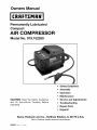
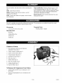
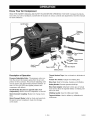
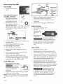
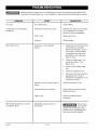
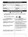
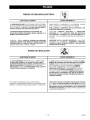
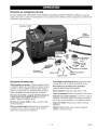
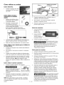
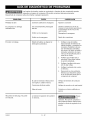
Owners Manual
I CRRFTSMRN°I
Permanently Lubricated
Compact
AIR COMPRESSOR
Model No. 919.152350
• Safety Guidelines
• Assembly
• Operation
• Maintenance
CAUTION:
Read the Safety Guidelines
and All Instructions
Carefully
Before
Operating.
• Service and Adjustments
• Troubleshooting
• Repair Parts
• Espahol
Sears,
Roebuck
and Co., Hoffman
Estates,
IL 60179
Visit our Craftsman website: www.sears.com/craftsman
A08593
Rev. 0
11/4/04
U.S.A.
SPECIFICATION
WARRANTY
CHART
..............................
SAFETY GUIDELINES
GLOSSARY
....................
...........................
...............................
Contents of Carton ......................
To Remove Air compressor
INSTALLATION
From Carton .....
............................
Location of Air Compressor
Grounding Instructions
...............
How to Use Your Unit ...................
10
How to Stop
10
Voltage and Circuit Protection
.............
..............
..........................
To Use Quick Connect Sockets and Plugs
7
To Use Female Tire Chuck
7
To Use Blow Gun ......................
10
7
Before Starting
10
7
How to Start ..........................
...............
10
........................
SERVICE AND ADJUSTMENTS
Air Hose Replacement
. .10
10
.............
..................
11
11
8
STORAGE
8
TROUBLESHOOTING
8
REPAIR PARTS ...........................
13
ESPAI_IOL ...............................
15
9-10
...............
9
7
8
...................
Know Your Air Compressor
Description of Operation ..................
2
8
Extension Cords ........................
OPERATING PROCEDURES
2
3-6
...............................
ACCESSORIES
ASSEMBLY
....................
9
...............................
GUIDE
11
...............
HOW TO ORDER REPAIR PARTS .....
12
back cover
SPECI FICATION CHART
Model No.
919-152350
Running Horsepower
Displacement CFM
Bore
1
4.8
1-7/8"
Stroke
1-1/4"
Voltage-Single Phase
Minimum Branch Circuit Requirement
120
10 amps
Fuse Type
SCFM @40 psig
SCFM @90 psig
Time Delay
3.7
2.6
FULL ONE YEAR WARRANTY
AIR COMPRESSOR
If this air compressor fails due to a defect in material or workmanship within one year from the date of
purchase, RETURN IT TO THE NEAREST SEARS REPAIR CENTER THROUGHOUT THE UNITED STATES
AND SEARS WILL REPAIR IT, FREE OF CHARGE. If purchased from Orchard Supply Hardware, return to
the nearest Orchard Store and Orchard will repair it, free of charge.
If this air compressor is used for commercial
from the date of purchase.
or rental purposes, the warranty will apply for ninety days
This warranty gives you specific legal rights and you may have other rights which vary from state to state.
Sears, Roebuck and Co., Dept. 817WA, Hoffman Estates, II 60179
A08593
2- ENG
SAFETY and PREVENTING EQUIPMENT PROBLEMS. To help you recognize this information,
below. Please read the manual and pay attention to these sections.
we use the symbols
Indicates an imminently hazardous
situation which, if not avoided, will
result in death or serious injury.
Indicates a potentially hazardous
situation which, if not avoided, may
result in minor or moderate injury.
Indicates a potentially hazardous situation which, if not avoided, could
result in death or serious injury.
Used without the safety alert symbol indicates a potentially hazardous situation which, if not avoided, may result in
property damaqe.
SAVE THESE INSTRUCTIONS
IMPROPER OPERATION OR MAINTENANCE OF THIS PRODUCT COULD RESULT IN SERIOUS INJURY
AND PROPERTY DAMAGE. READ AND UNDERSTAND ALL WARNINGS AND OPERATING INSTRUCTIONS BEFORE USING THIS EQUIPMENT.
RISK OF EXPLOSION
OR FIRE
HOW TO PREVENT IT
WHAT CAN HAPPEN
IT IS NORMAL FOR ELECTRICAL CONTACTS WITHIN
THE MOTOR AND PRESSURE SWITCH TO SPARK.
ALWAYS OPERATE THE COMPRESSOR
TILATED AREA FREE OF COMBUSTIBLE
GASOLINE OR SOLVENT VAPORS.
IN A WELL VENMATERIALS,
IF ELECTRICAL SPARKS FROM COMPRESSOR COME
INTO CONTACT WITH FLAMMABLE VAPORS, THEY
MAY IGNITE, CAUSING FIRE OR EXPLOSION.
IF SPRAYING FLAMMABLE MATERIALS, LOCATE COMPRESSOR AT LEAST 20 FEET AWAY FROM SPRAY
AREA. AN ADDITIONAL LENGTH OF HOSE MAY BE
REQUIRED.
STORE FLAMMABLE MATERIALS IN A SECURE LOCATION AWAY FROM COMPRESSOR.
RESTRICTING ANY OF THE COMPRESSOR VENTILATION OPENINGS WILL CAUSE SERIOUS OVERHEATING
AND COULD CAUSE FIRE.
NEVER PLACE OBJECTS AGAINST OR ON TOP OF
COMPRESSOR.
OPERATE COMPRESSOR IN AN OPEN
AREA AT LEAST 12 INCHES AWAY FROM ANY WALL
OR OBSTRUCTION THAT WOULD RESTRICT THE FLOW
OF FRESH AIR TO THE VENTILATION OPENINGS.
OPERATE COMPRESSOR IN A CLEAN, DRY, WELL VENTILATED AREA. DO NOT OPERATE UNIT INDOORS OR IN
ANY CONFINED AREA.
UNATTENDED OPERATION OF THIS PRODUCT COULD
RESULT IN PERSONAL INJURY OR PROPERTY DAMAGE.
ALWAYS REMAIN IN ATTENDANCE
UCT WHEN IT IS OPERATING.
3- ENG
WITH THE PROD-
A08593
RISK OF BURSTING
AIR TANK:
THE FOLLOWING
RESULT IN A VIOLENT
TANK
INJ URY.
CONDITIONS
COULD
LEAD TO A WEAKENING
OF THE TANK, AND
EXPLOSION
AND COULD CAUSE PROPERTY
DAMAGE
OR SERIOUS
WHAT CAN HAPPEN
HOW TO PREVENT IT
1.
FAILURE TO PROPERLY DRAIN CONDENSED
WATER FROM THE TANK, CAUSING RUST AND
THINNING OF THE STEEL TANK.
DRAIN TANK DALLY OR AFTER EACH USE. IF TANK
DEVELOPS A LEAK, REPLACE IT IMMEDIATELY WITH A
NEW TANK OR REPLACE THE ENTIRE COMPRESSOR.
2.
MODIFICATIONS OR ATTEMPTED REPAIRS TO THE
TANK.
NEVER DRILL INTO, WELD, OR MAKE ANY MODIFICATIONS TO THE TANK OR ITS ATTACHMENTS.
3.
UNAUTHORIZED MODIFICATIONS TO THE
UNLOADER VALVE, SAFETY VALVE, OR ANY
OTHER COMPONENTS WHICH CONTROL TANK
PRESSURE.
THE TANK IS DESIGNED TO WITHSTAND SPECIFIC OPERATING PRESSURES, NEVER MAKE ADJUSTMENTS OR
PARTS SUBSTITUTIONS TO ALTER THE FACTORY SET
OPERATING PRESSURES.
4,
EXCESSIVE VIBRATION CAN WEAKEN THE AIR
TANK AND CAUSE RUPTURE OR EXPLOSION.
ATTACHMENTS
& ACCESSORIES:
EXCEEDING THE PRESSURE RATING OF AIR TOOLS,
SPRAY GUNS, AIR OPERATED ACCESSORIES, TIRES AND
OTHER INFLATABLES CAN CAUSE THEM TO EXPLODE
OR FLY APART, AND COULD RESULT IN SERIOUS INJURY.
FOR ESSENTIAL CONTROL OF AIR PRESSURE, YOU
MUST INSTALL A PRESSURE REGULATOR AND PRESSURE GAUGE TO THE AIR OUTLET OF YOUR COMPRESSOR. FOLLOW THE EQUIPMENT MANUFACTURERS
RECOMMENDATION AND NEVER EXCEED THE MAXIMUM
ALLOWABLE
PRESSURE RATING OF ATTACHMENTS.
NEVER USE COMPRESSOR TO INFLATE SMALL LOWPRESSURE OBJECTS SUCH AS CHILDREN'S
TOYS,
FOOTBALLS, BASKETBALLS, ETC.
RISK FROM FLYING OBJECTS
HOW TO PREVENT IT
WHAT CAN HAPPEN
THE COMPRESSED AIR STREAM CAN CAUSE SOFT TISSUE DAMAGE TO EXPOSED SKIN AND CAN PROPEL
DIRT, CHIPS, LOOSE PARTICLES AND SMALL OBJECTS
AT HIGH SPEED, RESULTING IN PROPERTY DAMAGE OR
PERSONAL INJURY.
ALWAYS WEAR ANSI Z87.1 APPROVED SAFETY GLASSES WITH SIDE SHIELDS WHEN USING THE COMPRESSOR.
NEVER POINT ANY NOZZLE OR SPRAYER TOWARD
ANY PART OF THE BODY OR AT OTHER PEOPLE OR
ANIMALS.
ALWAYS TURN THE COMPRESSOR
OFF AND BLEED
PRESSURE FROM THE AIR HOSE AND TANK BEFORE
ATTEMPTING MAINTENANCE, ATTACHING TOOLS OR
ACCESSORIES.
A08593
4-ENG
RISK OF ELECTRICAL
SHOCK
HOW TO PREVENT IT
WHAT CAN HAPPEN
YOUR AIR COMPRESSOR IS POWERED BY ELECTRICITY. LIKE ANY OTHER ELECTRICALLY POWERED DEVICE,
IF IT IS NOT USED PROPERLY IT MAY CAUSE ELECTRIC
SHOCK.
NEVER OPERATE THE COMPRESSOR OUTDOORS WHEN
IT IS RAINING OR IN WET CONDITIONS.
NEVER OPERATE COMPRESSOR
COVERS REMOVED OR DAMAGED,
WITH
PROTECTIV-
REPAIRS ATTEMPTED BY UNQUALIFIED
PERSONNEL
CAN RESULT IN SERIOUS INJURY OR DEATH BY ELECTROCUTION.
ANY ELECTRICAL WIRING OR REPAIRS REQUIRED ON
THIS PRODUCT SHOULD BE PERFORMED BY AUTHORIZED SERVICE CENTER PERSONNEL IN ACCORDANCE
WITH NATIONAL AND LOCAL ELECTRICAL CODES.
ELECTRICAL GROUNDING:
FAILURE TO PROVIDE ADEQUATE GROUNDING
TO THIS PRODUCT
COULD
RESULT IN SERIOUS INJURY OR DEATH FROM ELECTROCUTION.
SEE GROUNDING INSTRUCTIONS,
MAKE CERTAIN THAT THE ELECTRICAL CIRCUIT TO
WHICH THE COMPRESSOR IS CONNECTED PROVIDES
PROPER ELECTRICAL GROUNDING,
CORRECT VOLTAGE AND ADEQUATE FUSE PROTECTION.
RISK TO BREATHING
WHAT CAN HAPPEN
HOW TO PREVENT IT
THE COMPRESSED AIR DIRECTLY FROM YOUR COMPRESSOR IS NOT SAFE FOR BREATHING. THE AIR
STREAM MAY CONTAIN CARBON MONOXIDE, TOXIC
VAPORS, OR SOLID PARTICLES FROM THE TANK.
BREATHING THESE CONTAMINANTS CAN CAUSE
SERIOUS INJURY OR DEATH.
AIR OBTAINED DIRECTLY FROM THE COMPRESSOR
SHOULD NEVER BE USED TO SUPPLY AIR FOR HUMAN
CONSUMPTION.
IN ORDER TO USE AIR PRODUCED BY
THIS COMPRESSOR FOR BREATHING, SUITABLE FILTERS AND IN-LINE SAFETY EQUIPMENT
MUST BE
PROPERLY INSTALLED, IN-LINE FILTERS AND SAFETY
EQUIPMENT USED IN CONJUNCTION WITH THE COMPRESSOR MUST BE CAPABLE OF TREATING AIR TO ALL
APPLICABLE
LOCAL AND FEDERAL CODES PRIOR TO
HUMAN CONSUMPTION.
SPRAYED MATERIALS SUCH AS PAINT, PAINT SOLVENTS, PAINT REMOVER, INSECTICIDES, WEED
KILLERS, CONTAIN HARMFUL VAPORS AND POISONS.
WORK IN AN AREA WITH GOOD CROSS-VENTILATION.
READ AND FOLLOW THE SAFETY INSTRUCTIONS PROVIDED ON THE LABEL OR SAFETY DATA SHEETS FOR
THE
MATERIAL
YOU
ARE
SPRAYING.
USE A
NIOSH/MSHA APPROVED RESPIRATOR DESIGNED FOR
USE WITH YOUR SPECIFIC APPLICATION,
5- ENG
A08593
RISK OF BURNS
WHAT CAN HAPPEN
HOW TO PREVENT IT
TOUCHING EXPOSED METAL SUCH AS THE COMPRESSOR HEAD OR OUTLET TUBES, CAN RESULT IN
SERIOUS BURNS.
NEVER TOUCH ANY EXPOSED METAL PARTS ON
COMPRESSOR DURING OR IMMEDIATELY AFTER OPERATION. COMPRESSOR WILL REMAIN HOT FOR SEVERAL
MINUTES AFTER OPERATION.
DO NOT REACH AROUND
ATTEMPT
MAINTENANCE
ALLOWED TO COOL.
RISK FROM MOVING
PROTECTIVE SHROUDS OR
UNTIL UNIT HAS BEEN
PARTS
WHAT CAN HAPPEN
HOW TO PREVENT IT
MOVING PARTS SUCH AS THE PULLEY, FLYWHEEL AND
BELT CAN CAUSE SERIOUS INJURY IF THEY COME
INTO CONTACT WITH YOU OR YOUR CLOTHING,
NEVER OPERATE THE COMPRESSOR
WITH GUARDS
OR COVERS WHICH ARE DAMAGED OR REMOVED.
ATTEMPTING TO OPERATE COMPRESSOR WITH DAMAGED OR MISSING PARTS OR ATTEMPTING TO REPAIR
COMPRESSOR WITH PROTECTIVE SHROUDS REMOVED
CAN EXPOSE YOU TO MOVING PARTS AND CAN
RESULT IN SERIOUS INJURY.
ANY REPAIRS REQUIRED ON THIS PRODUCT SHOULD
BE PERFORMED BY AUTHORIZED
SERVICE CENTER
PERSONNEL.
RISK OF FALLING
WHAT CAN HAPPEN
HOW TO PREVENT IT
A PORTABLE COMPRESSOR CAN FALL FROM A TABLE,
WORKBENCH OR ROOF CAUSING DAMAGE TO THE
COMPRESSOR
AND COULD RESULT IN SERIOUS
INJURY OR DEATH TO THE OPERATOR.
RISK OF PROPERTY
DAMAGE WHEN
COMPRESSOR
(Fire, Inhalation,
For units requiring
Damage
ALWAYS OPERATE
COMPRESSOR
IN A STABLE
SECURE POSITION TO PREVENT ACCIDENTAL MOVEMENT OF THE UNIT. NEVER OPERATE COMPRESSOR
ON A ROOF OR OTHER ELEVATED POSITION.
USE
ADDITIONAL AIR HOSE TO REACH HIGH LOCATIONS.
TRANSPORTING
to Vehicle Surfaces)
oil in pump
or gasoline
engines
WHAT CAN HAPPEN
HOW TO PREVENT IT
OIL CAN LEAK OR SPILL AND COULD RESULT IN FIRE
OR BREATHING HAZARD, SERIOUS INJURY OR DEATH
CAN RESULT. OIL LEAKS WILL DAMAGE CARPET, PAINT
OR OTHER SURFACES IN VEHICLES OR TRAILERS,
A08593
ALWAYS PLACE COMPRESSOR ON A PROTECTIVE MAT
WHEN TRANSPORTING TO PROTECT AGAINST DAMAGE
TO VEHICLE FROM LEAKS, REMOVE COMPRESSOR
FROM VEHICLE IMMEDIATELY UPON ARRIVAL AT YOUR
DESTINATION.
6 - ENG
Become familiar with these terms before operating the
unit.
CFM:
Cubic feet per minute.
SOFM: Standard cubic feet per minute; a unit of
measure of air delivery.
PSlG: Pounds per square inch gauge; a unit of measure of pressure.
Code Certification:
Products that bear one or more
of the following marks: UL, CUL, ETL, CETL, have
been evaluated by ©SHA certified independent safety
laboratories and meet the applicable Underwriters
Laboratories Standards for Safety.
Branch Circuit: Circuit carrying electricity from electrical panel to outlet
This unit is capable of powering the following Accessories. The accessories are available through the current
Power and Hand Tool Catalog or full-line Sears stores.
Accessories
Carpentry
Quick Connect Sets (various sizes)
Specialty
Tools
Finishing Nailer / Stapler
Tools
Air Brush
Inflating/Blow
Gun
Grease Gun
Caulk Gun
Contents
of Carton
1.
Air Compressor with hose and pressure
adjustment valve (qty 1)
2.
Quick Connect Coupling (qty 1)
3.
Quick Connect Studs (qty 2)
4.
Thread Sealant Tape (qty 1)
5.
Female Tire Chuck (qty 1)
6.
Blow Gun (qty 1)
7.
Safety Nozzle (qty 1)
8.
Blow Gun Adapter (qty 1)
9.
Inflating Needle (qty 1)
9
10. Tapered Inflator (qty 1)
8
To Remove Air Compressor From Carton
1.
Grasp handle and lift the air compressor out of
the carton.
2.
Remove all packaging from air compressor and
discard.
7- ENG
A08593
IMPROPER GROUNDING
RESULT IN ELEC-
HOW TO SET UP YOUR UNIT
Location
TRICAL SHOCK.
of the Air Compressor
Do not modify the plug provided. If it does
not fit the available outlet, a correct outlet
should be installed by a qualified electrician.
Locate the air compressor in a clean, dry and well
ventilated area. The air compressor pump and shroud
are designed to allow for proper cooling. The ventilation openings on the compressor are necessary to
maintain proper operating temperature. Do not place
rags or other containers on or near these openings.
Repairs to the cord set or plug MUST be
made by a qualified electrician.
Extension
GROUNDING
INSTRUCTIONS
Use extra air hose instead of an extension cord to
RISK OF ELECTRICAL
SHOCK. In the event of a
short circuit, grounding reduces the risk of
shock by providing an escape wire for the
electric current. This air compressor must be
properly grounded.
avoid voltage drop and power loss to the motor, and
to prevent overheating.
If an extension cord must be used, be sure it is:
•
The portable air compressor is equipped with a cord
having a grounding wire with an appropriate grounding plug (see following illustrations). The plug must be
used with an outlet that has been installed and
grounded in accordance with all local codes and ordinances.
1.
Cords
The cord set and plug with this unit contains a
grounding pin. This plug MUST be used with a
grounded outlet.
a 3-wire extension cord that has a 3-blade
grounding plug, and a 3-slot receptacle that will
accept the plug on the product
•
in good condition
•
no longer than 50 feet
•
14 gauge (AWG) or larger. (Wire size increases as
gauge number decreases. 12 AWG, 10 AWG, and
8 AWG may also be used. DO NOT USE 16 OR
18 AWG.)
Voltage and Circuit
Protection
IMPORTANT: The outlet being used must be installed
and grounded in accordance with all local codes and
ordinances.
Refer to the Parts Manual for the voltage and minimum branch circuit requirements.
2.
Certain air compressors can be operated on a 15 amp
circuit if the following conditions are met.
Make sure the outlet being used has the same
configuration as the grounded plug. DO NOT USE
AN ADAPTER. See figure.
@
--_
Grounded
/
Outlets
4.
Inspect the plug and cord before each use. Do
not use if there are signs of damage.
If these grounding instructions are not completely
understood, or if in doubt as to whether the compressor is properly grounded, have the installation
checked by a qualified electrician.
A08593
Voltage supply through branch circuit is 15 amps.
2.
Circuit is not used to supply any other electrical
needs (lights, appliances, etc.).
3.
Extension cords comply with specifications.
4.
Circuit is equipped with a 15 amp circuit breaker
or 15 amp time delay fuse. NOTE: If compressor
is connected to a circuit protected by fuses, use
only time delay fuses marked "D".
If any of the above conditions cannot be met, or if
operation of the compressor repeatedly causes interruption of the power, it may be necessary to operate it
from a 20 amp circuit. It is not necessary to change
the cord set.
Grounding Pin
3.
1.
8-ENG
Know Your Air Compressor
READ THIS OWNER'S MANUAL AND SAFETY RULES BEFORE OPERATING YOUR UNIT. Compare the illustrations with your unit to familiarize yourself with the location of various controls and adjustments. Save this manual
for future reference.
On/Off Switch
Pressure
Adjustment
Connect
Quick Connect
Coupling
Tapered Inflator
Inflating Needle
Description
of Operation
Pressure Adjustable Valve: The pressure valve controls the amount of pressure going from the air compressor to the accessory. The pressure adjusting valve
can be used to set approximate pressure between 10
and 125 PSI (125 PSI is the highest pressure this
compressor will deliver).
On/Off Switch (located on opposite side of air
compressor): Used to turn air compressor on and off.
Quick Connect
easy.
Coupling:
Thread Sealant Tape: Use on threads to eliminate air
leaks.
Female Tire Chuck: Adapter for inflating tires.
Blow Gun: Ideal for blowing, cleaning, and inflating.
Safety Nozzle: Prevents pressure build-up.
Blow Gun Adapter: Attached to blow gun or female
hose end to allow the tapered Inflator or inflating needle to be used.
Inflating
Makes tool change overs
Quick Connect Studs: Install on tools and insert into
the quick connect coupling to make tool change
overs easier.
needle: Used to inflate sport balls.
Tapered Inflator:
mattresses.
9- ENG
Used to inflate toy inflatables/air
A08593
I
How to Use Your Unit
Lever
How to Stop:
1.
Blow
Gun
Adapter
Inflating Needle
Set the On/Off switch to
"OFF".
Tapered Inflator
Safety
Nozzle
To Use Quick Connect
Coupling
1.
2.
and Studs
Apply thread sealant tape
to threads of quick connect coupling and studs,
Assemble the quick connect coupling to the hose,
Attach the studs to the
blow gun and female tire chuck. Tighten securely,
This will make it easier to change over these
accessories.
3.
Pull quick connect coupling back and insert stud.
See figure above,
4.
Slide coupling forward to lock in place,
To Use Female
3.
Attach the inflating needle or tapered inflator to
the blow gun adapter on the blow gun.
4.
See the "How to Start" paragraph to start air
compressor.
5.
Depress lever on blow gun to release the air.
Before Starting:
1.
Place On/Off switch to "OFF".
2.
Place the
adjustable pressure valve to 10
PSI.
2.
Attach hose and
accessories.
Too much air pressure
causes a hazardous risk of
bursting. Check the manufacturer's maximum
pressure rating for air tools and accessories.
Carefully follow the "How to Start" instructions.
Tire Chuck
1.
Attach female tire chuck to hose.
How to Start:
2.
See the "How to Start" paragraph to start air
compressor.
1.
Place On/Off switch to "OFF".
2.
Plug the power cord into the grounded outlet.
3.
Place the female tire chuck onto the tire valve
stem of the tire to be inflated.
3.
Place On/Off switch to "ON" to start compressor.
4.
Check the manufacturer's maximum pressure rating for the air tool, accessory, or vehicle tire being
used. The air compressor outlet pressure must
never exceed the maximum pressure rating.
,
Slowly increase the pressure setting of the
adjustable pressure valve to the tire manufacturer's recommended PSI. Note: To ensure correct
tire pressure use a tire pressure gauge.
5,
To Use Blow Gun
1,
Attach the blow gun to hose.
If an accessory
is not being
used with the blow gun, the
safety nozzle MUST be
assembled.
2.
Compressed air from the
outfit may contain water
condensation.
Do not spray unfiltered air at
an item that could be damaged. Some air
operated tools or devices may require filtered
air. Read the instructions for the air tool or
device.
Safety Nozzle
Assemble the safety nozzle or blow gun adapter
to blow gun. See next figure.
NOTE: To use the inflating needle or tapered inflator
the blow gun adapter has to be assembled to blow
gun.
A08593
Slowly increase the pressure setting of the
adjustable pressure valve. You should be able to
hear and feel air pressure being relieved by the
adjustable pressure valve. If pressure is not being
relieved, turn the air compressor off immediately.
The pressure valve must be replaced.
10-ENG
DO NOT replace the hose
with standard hose that is
Air Hose Replacement
The air hose attached to your compressor has an
integral pressure adjusting valve at the working end of
the hose. Should service or replacement be required,
make sure that the pressure adjusting valve is present
in the air hose line.
1.
2.
not equipped with the pressure adjusting
valve. The appropriate hose assembly for
your compressor is available at Sears.
Do not allow hose to
become kinked or
pinched at any time. This is important to
avoid damage to your compressor and to
maintain pressure adjusting valve control.
3.
Set the On/Off switch to "OFF" and unplug the
cord.
Relieve all pressure from the air compressor head
and air hose by turning the adjustable pressure
valve to 10 PSI.
Protect the electrical cord and air hose from damage by winding them loosely around the air compressor.
4.
11- ENG
Store the air compressor
tion.
in a clean and dry loca-
A08593
Voltage sources, moving parts, or compressed air sources are exposed when repairing the
compressor. Personal injury can occur. Unplug the compressor before attempting any repairs.
PROBLEM
CAUSE
CORRECTION
Air Leaks
Hose fitting loose.
Tighten fitting.
Compressor is not delivering
enough air.
Prolonged excessive use of air.
Decrease the amount of air usage.
Your compressor is not large
enough for the air requirement.
Hole in hose.
Replace the hose.
Air leaks.
Tighten fittings.
Motor will not run.
Fuse blown, circuit breaker
tripped.
1.
Check fuse box for blown fuse
and replace as necessary.
Reset circuit breaker. Do not
use a fuse or circuit breaker
with higher rating than that
specified for your particular
branch circuit.
High discharge pressure.
be adjusted lower.
A08593
Cannot
2.
Check for proper fuse. You
should be using a "Time
Delay" fuse.
3.
Check for low voltage problem.
4.
Check the extension cord.
5.
Disconnect the other electrical
appliances from circuit or
operate the compressor on its
own branch circuit.
Extension cord is wrong length or
gauge.
Check the extension cord.
Loose electrical connections.
Check wiring connection
terminal box area.
Faulty motor.
Contact a Trained Service
Technician.
Adjustable pressure valve not
functioning.
Risk of bursting. DO NOT
operate the compressor if this
problem exists. Adjustable pressure valve must be replaced.
12 - ENG
inside
14
19 Torque
30-45 in.-Ibs.
/
15
16
/
21
23
22
3
7
17
22
\
18
KEY
NO
1
2
3
4
5
6
7
8
9
9-8
9-9
9-10
9-11
9-12
9-13
12
13
14
15
16
17
18
19
2O
21
22
23
PART NO.
SSF-995
CAC-1196
CAC-1212
CAC-1199
Z-A08548
SSG-8169
AC-0187-1
Z-A04615
+
X
D21127
SSF-3147
+
×
×
AC-0815
D25731
CAC-1319-1
D21709
CAC-1320
CAC-1206-1
CAC-4324
SUDL-9-1
SSS-16
SSF-3156
CAC-1211
D21708
DESCRIPTION
Screw #10-24 x 718 (4)
Cylinder Head
Tube Seal
Head Gasket
Valve Plate Assembly
"O" Ring
Outlet Tube
Gasket
Sub Pump Assembly
Rod Assembly
Pre-Formed Compression Ring
Connecting Rod Cap
Screw #10-24
Screw 3/8-16 UNC
Cylinder Sleeve
Timing Belt
Pump Isolator (5)
Shroud (left)
Label, Tool Rating
Shroud (right)
Clamp
Pressure Valve Assembly and Hose
Screw, Ground
Switch
Shroud Screws (5)
Housing Isolator (3)
Label, Performance
NOT ILLUSTRATED/NO
x
>
+
KK-4929
KK-4964
D30139
D30324
A08593
LA-3146
D23786
D23787
DESCRIPCION
Tornillo #10-24 x 7/8 (4)
Cabezal del cilindro
Sello del tubo
Junta - Cabezal
Placa de la valvula
Anillo "O"
Tubo de salida
Junta
Conjunto de Sub-Bomba
Ensamblaje de la biela
Ring Anillo de compresidn preformado
Tapa de la barra de conexi6n
Tornillo #10-24
Tornillo 3/8-16 UNC
Manga del Cilindro
Correa de regulaci6n
Aislante de pompe (5)
Cubierta, izquierda
R6tulo, grade de la herramienta
Lubierta, derecha
Abrazadera
Valvula de presidn y manguera
Tornillos para Tierra
Interruptor
Tornillos para la cubierta (5)
Aislante del casco (3)
R6tulo, funcionamiento
SE MUSTRAN
Fastener Kit
Connecting Rod Kit
Gasket & Seal Kit
Ring Kit
Owner's Manual
Label, Warning
Power Cord
Jumper Wire
El juego de sujetadores
El juego de la barra de conexi6n
Juego de empaquetaduras y sellos
Conjunto de sujeci6n juego de anillo
Manual del propietario
R6tulo, advertencia
Cable electrico
Alambre de puente
13-ENG
A08593
HOJA DE ESPECIFICACIONES
GARANTIA
................................
NORMAS DE SEGURIDAD
GLOSARIO
...............
................
14
Descripci6n de operaciones ................
21
14
Come usar su unidad .....................
22
Come detenerla
22
15-18
................................
.........................
19
C6mo utilizar z6calos y enchufes de
ACCESORIOS
.............................
19
conexi6n r_.pida .........................
22
ENSAMBLADO
.............................
19
C6mo utilizar el pico hembra para el inflado
de los neum6.ticos .......................
C6mo utilizar la pistola sopladora ...........
22
22
Antes de comenzar
......................
22
C6mo dar arranque
......................
22
Contenido de la caja
.....................
19
C6mo extraer el compresor de aire de la caja..19
INSTALACION
.............................
Ubicaci6n del compresor
Instrucciones
20
de aire ............
20
para conectar a tierra .........
20
Extensiones el@ctricas ....................
Protecci6n del voltaje y del circuito
PROCEDIMIENTOS
OPERATIVOS
Conozca su compresor
SERVIClOS Y REGULAClONES
..........
20
21-22
de aire .............
21
23
Reemplazo de la manguera de aire ..........
20
..........
...............
ALMACENAJE
.............................
GUlA DE DIAGNOSTICO
PIEZAS DE REPARACION
23
DE PROBLEMAS
......
...................
24
13
COMO SOUCITAR PIEZAS PAPA REPARACION
...............................
contratapa
HOJA DE ESPECIFICACIONES
Modelo
919-152350
Potwncia de trabajo
CFM de desplazamiento
Di_.metro
0,1
4,8
1-7/8"
Carrera
1- 1/4"
Voltaje - Monof_.sico
120
Requerimientos minimo por circuito ramal 10 A
Tipo de fusible
Acci6n retardada
SCFM a 40 PSIG
3,7
SCFM a 90 PSIG
2,6
GARANTIA COMPLETA POR UN AI_IO
COMPRESOR DE AIRE
Si este compresor de aire fallara por defectos en materiales o mano de obra dentro del lapso de un aSo a partir de la
fecha de su compra, DEVUC:LVALO
AL CENTRO DE REPARACIONESSEARS MAS CERCANO DENTRO DE LOS
ESTADOSUNIDOS, Y SEARS LO REPARARA,LIBRE DE CARGO. Si se hubiese comprado a Orchard Supply
Hardware, devu@lvaloal comercio Orchard mas cercano y Orchard Io reparar_.,libre de cargo.
Si este compresor de aire fuese utilizado para propositos comerciales o de alquiler, la garantia solo tendra validez
por noventa dias a partir de la compra.
Esta garantia le otorga derechos legales especificos, aunque usted podr_,tener otros derechos que podrian variar
entre estados.
Sears, Roebuck and Co., Dept. 817WA, Hoffman Estates, II 60179
A08593
23
14- SP
SEGURIDAD Y PREVENCION DE PROBLEMAS DEL EQUIPO: Para ayudar al reconocimiento
de esta informaciOn, hemos
utilizado los simbolos mostrados abajo. Sfrvase leer el manual y prestar atenciOn a dichas secciones.
Indica una situaci6n de inminente riesgo, la cual,
si no es evitada, causarA la muerte o lesiones
_lndica
serias.
resultar
resultar en la muerte
Indica una situaciOn potencialmente
riesgosa, que si no es evitada,
o lesiones serias.
en lesiones
una situaciOn
potencialmente
peligrosa, la cual, si no es evitada, podria
menores o moderadas.
Usado sin el simbolo de seguridad de
alerta indica una situaci6n
potencialmente riesgosa la que, si no es evitada, podria causar dafios en
la propiedad.
podria
GUARDE ESTAS INSTRUCClONES
La operacibn o el mantenimiento inadecuados de este producto podrian ocasionar serias lesiones y
dafios a la propiedad. Lea y comprenda todas las advertencias e instrucciones de funcionamiento
antes de utilizar este equipo.
RIESGO
DE EXPLOSION
&QUI_ PUEDE
O INCENDIO
_,C6MO PREVENIRLO?
OCURRIR?
PARA LOS CONTACTOS ELI_CTRICOS ES NORMAL
EXISTENCIA DE CHISPAS ENTRE EL MOTOR Y EL
INTERRUPTOR A PRESION.
LA
OPERE SIEMPRE EL COMPRESOR EN UN SECTOR BIEN
VENTILADO
Y LIBRE
DE MATERIALES
COMBUSTIBLES,
GASOLINA O EMANAClONES
DE SOLVENTE.
EN UN AREA DE ROCIADO
SI LAS CHISPAS EL¢CTRICAS PROVENIENTES DEL COMPRESOR
TOMARAN CONTACTO CON EMANACIONES
DE MATERIALES
INFLAMABLES,
ELLOS PODRIAN ARDER ORIGINANDO
INCENDIO O EXPLOSION.
DE MATERIALES
INFLAMABLES,
UBIQUE AL COMPRESOR POR LO MENOS A 6,1M (20 PIES) DE
DISTANCIA DEL h.REA DE ROCIADO. PODRiA REQUERIRSE
UNA EXTENSION DE LA MANGUERA.
ALMACENE
UBICACION
LOS MATERIALES INFLAMABLES
EN UNA
SEGURA, ALEJADOS DEL COMPRESOR.
JAMAS COLOQUE OBJETOS APOYADOS O SOBRE EL COMPRESOR. OPERE EL COMPRESOR
EN UN SECTOR ABIERTO,
RESTRINGIR CUALQUIERA DE LAS ABERTURAS DE
VENTILAClON
CAUSARA UN SERIO RECALENTAMIENTO
Y PODRIA PRODUCIR UN INCENDIO.
POR LO MENOS A 30 CM (12 PULGADAS)
ALEJADO
DE
CUALQUIER
PARED U OBSTRUCCION
QUE RESTRINJA EL
FLUJO DE AIRE FRESCO A LAS ABERTURAS DE VENTILACION.
OPERE EL COMPRESOR EN UN SECTOR LIMPIO, SECO, Y BIEN
VENTILADO. NO OPERE LA UNIDAD EN ESPACIOS CERRADOS
O CUALQUlER ,&,REA CONFINADA.
DEJAR DESATENDIDO
ESTE PRODUCTO
MIENTRAS
MISMO EST,&. EN FUNCIONAMIENTO
PUEDE RESULTAR
LESlONES PERSONALES O DAI_IOS A LA PROPIEDAD.
EL
EN
15- SP
MANTleNGASE SlEMPRE ALERTA CADA VEZ QUE EL
PRODUCTO ESTE FUNCIONANDO.
A08593
RIESGO
DE EXPLOSION
TANQUE DE AIRE:
LAS SIGUIENTES CONDICIONES PUEDEN DETERMINAR EL DEBILITAMIENTO
DEL TANQUE, Y ORIGINAR UNA VIOLENTA EXPLOSION DEL MISMO, SIENDO CAUSA DE DAhlOS A
LA PROPIEDAD 0 LESIONES SERIAS.
_,QU¢: PUEDE OCURRIR?
2.
3.
&C6MO
PREVENIRLO?
DRENAJE INADECUADO DEL AGUA CONDENSADA
EN
EL TANQUE, SIENDO LA CAUSA DEL OXIDO QUE REDUCE
EL ESPESOR DEL TANQUE DE ACERO.
DRENE EL TANQUE DIARIAMENTE O DESPUI_S DE CADA USO.
Sl EL TANQUE GENERA UNA PCRDIDA, REEMPLikCELO
INMEDIATAMENTE CON UN NUEVO TANQUE O REEMPLACE EL
COMPRESOR COMPLETO.
MODIFICACIONES
TANQUE.
JAMAS PERFORE, SUELDE, O EFECTUE MODIFICACION
AL TANOUE O SUS ACCESORIOS.
O INTENTO DE REPARACIONES
AL
ALGUNA
EL TANQUE ESTik DISENADO PARA RESISTIR PRESIONES
OPERATIVAS ESPECiFICAS.
JAMAS
EFECTUE AJUSTES
O
SUSTITUYA PARTES QUE ALTEREN LAS REGULACIONES DE
PRESION ORIGINALES DE FABRICA.
MODIFICACIONES
NO AUTORIZADAS
A LA VALVULA DE
DESCARGA, VALVULA DE SEGURIDAD 0 CUALQUIER
OTRO COMPONENTE
QUE CONTROLE LA PRESION DEL
TANQUE.
LA VIBRACION EXCESIVA PUEDE DEBILITAR EL TANQUE
DE AIRE Y CAUSAR SU RUPTURA O EXPLOSION.
AGREGADOS
Y ACCESORIOS
EL EXCESO A LOS VALORES DE PRESION ESTABLECIDOS
PARA I.AS HERRAMIENTAS NEUMATICAS, PISTOLAS ROGIADORAS, ACCESORIOS ACTIVADOS POR AIRE, CUBIERTAS Y OTROS
OBJETOS INFLABLES, PUEDE CAUSAR SU EXPLOSION O SER
ARROJADOS, PUDIENDO OCASIONAR SERIAS LESIONES.
RIESGO
DE OBJETOS
ARROJADOS
PARA UN CONTROL ESENCIAL DE LA PRESION, DEBE USTED
INSTALAR UN REGULADOR Y UN MEDIDOR DE PRESlON A LA
SALIDA DEL AIRE DE SU COMPRESOR. (Sl NO ESTUNIER
EQUIPADO) SIGA LAS RECOMENDACIONES
DE LOS
FABRICANTES DE SU EQUIPO Y JAMAS EXCEDA LOS VALORES
M/kXIMOS DE PRESION PERMITIDOS PARA LOS ACCESORIOS.
JAMAS USE EL COMPRESOR
PARA INFLAR OBJETOS QUE
REOUIEREN
POOA
O BAJA
PRESlON,
TALES
COMO
JUGUETES PARA LOS NII_IOS, PELOTAS DE FUTBOL, PELOTAS
DE BASQUET, ETC.
POR EL AIRE.
&C6MO
_,QU¢: PUEDE OCURRIR?
EL CHORRO
DE AIRE COMPRIMIDO
PUEDE CAUSAR
DAI_IOS
SOBRE LOS TEJIDOS BLANDOS DE LA PIEL EXPUESTA, Y
PUEDE
PROPULSAR
SUCIEDAD,
ASTILLAS,
PARTICULAS
SUELTAS Y PEQUE_IOSOBJETOS A ALTA VELOClDAD, OCASIONANDO
DANOS A LA PROPIEDAD O LESIONES PERSONALES.
AL UTILIZAR
SEGURIDAD
LATERAL.
JAMAS
PREVENIRLO?
EL COMPRESOR, USE SIEMPRE ANTEOJOS DE
ANSI Z87.1 APROBADOS,
CON PROTEOCION
APUNTE
NINGUNA
BOQUlLLA
O PULVERIZADOR
HAOIA PARTES DEL CUERPO, A OTRAS PERSONAS
ANIMALES.
APAGUE SIEMPRE
EL COMPRESOR
Y PURGUE
O
LA PRESION
DE LA MANGUERA DEL AIRE Y DEL TANQUE, ANTES DE INTENTAR
EL MANTENIMIENTO, EL ACOPLE DE HERRAMIENTAS O
ACCESORIOS.
A08593
16- SP
RIESGO
_QUEPUEDE
DE DESCARGA
ELI=CTRICA
_C6MO
OCURRIR?
PREVENIRLO?
SU COMPRESOR DE AIRE ESTA ACCIONADO POR ELECTRICIDAD.
COMO CUALQUIER OTRO DISPOSITIVO ELECTRICO IMPULSADO
EL¢CTRICAMENTE,
Sl NO SE LO UTILIZA ADECUADAMENTE,
PODRiA CAUSARLE UNA DESCARGA ELleCTRICA.
JAMAS OPERE EL COMPRESOR A LA INTEMPERIE
ESTA LLOVlENDO O EN CONDICIONES DE HUMEDAD.
LAS REPARAClONES INTENTADAS POR PERSONAL NO
CALIFICADO
PODRIAN OCASlONAR SERIAS LESlONES
MUERTE POR ELECTROCUCION.
CUALQUIER
CUANDO
NUNCA OPERE EL COMPRESOR SIN SUS DEFENSAS
CUBIERTAS REMOVIDAS O DAI_IADAS.
CONEXlON
ELleCTRICA
O
O SUS
REPARACION
O LA
REQUERIDA POR ESTE PRODUCTO DEBE SER EFECTUADA
POR PERSONAL AUTORIZADO
DE LOS SERVICENTROS
DE
ACUERDO
A LOS CODIGOS
ELECTRICOS
NACIONALES
Y
LOCALES.
CONEXION A TIERRA: DEJAR DE PROVEER UNA ADECUADA
CONEXlON A TIERRA A ESTE PRODUCTO PODRiA OCASlONAR
LESlONES SERIAS O LA MUERTE POR ELECTROCUCION.
VER
INSTRUCCIONES PARA LA PUESTA A TIERRA.
ASEGURESE QUE EL CIRCUITO ELleCTRICO AL CUAL ESTA
CONECTADO
EL COMPRESOR,
SUMINISTRA
APROPIADA
CONEXlON A TIERRA, TENSION CORRECTA Y UNA ADECUADA
PROTECCION DE FUSlBLES.
RIESGO
DE INHALACION
&QU¢: PUEDE OCURRIR?
_,COMO PREVENIRLO?
EL AIRE COMPRIMIDO
PROVENIENTE DEL COMPRESOR NO
ES SANO PARA RESPIRAR. EL CHORRO DE AIRE PUEDE
CONTENER MONOXlDO DE CARBONO, VAPORES T(_XlCOS O
PART[CULAS SOLIDAS PROVENIENTES DEL TANQUE. LA
INHALACION DE DICHOS CONTAMINANTES
PUEDE LLEGAR A
CAUSAR SERIAS LESlONES O LA MUERTE.
EL ROCIADO DE MATERIALES TALES COMO PINTURA,
SOLVENTES, REMOVEDORES DE PINTURA, INSECTICIDAS, MATA
HIERBAS, CONTIENEN EMANACIONES DAi_INAS Y VENENOSAS.
EL AIRE OBTENIDO DIRECTAMENTE DEL COMPRESOR JAMAS
DEBERA SER UTILIZADO PARA PROVEER AIRE PARA CONSUMO
HUMANO. PARA PODER UTILIZAR EL AIRE PRODUCIDO POR
ESTE COMPRESOR Y HACERLO RESPIRABLE, DEBERAN
INSTALARSE UN FILTRO ADECUADO Y UN EQUlPO DE
SEGURIDAD INTERCALADO. LOS FILTROS INTERCALADOS
TANTO COMO EL EQUIPO DE SEGURIDAD UTILIZADO EN
CON JUNTO CON EL COMPRESOR, DEBERAN SER CAPACES
DE PROCESAR EL TRATAMIENTO DEL AIRE DE ACUERDO A
TODOS LOS CODIGOS LOCALES Y FEDERALES, PREVIO AL
CONSUMO HUMANO.
TRABAJE EN UN .&.REA CON BUENA VENTILACION CRUZADA.
LEA Y SIGA LAS INSTRUCCIONES
DE SEGURIDAD PROVISTAS
EN EL ROTULO O EN LOS DATOS DE LAS HOJAS DE SEGURIDAD
DEL MATERIAL QUE EST.&.PULVERIZANDO. USE EL RESPIRADOR
APROBADO NIOSH/MSHA
DESIGNADO PARA UTILIZARSE CON
SU APLICACION ESPEC[FICA.
17 - SP
A08593
RIESGO
DE QUEMADURAS
_,QU¢: PUEDE OCURRIR?
TOCAR
EL METAL EXPUESTO
TAL COM©
&COMO
EL CABEZAL
PREVENIRLO?
JAMAS TOQUE PARTES DE METAL EXPUESTAS EN EL
COMPRESOR
DURANTE O INMEDIATAMENTE DESPUt_S DE LA
OPERACION.
EL OOMPRESOR
PERMANECERA
CALIENTE
POR VARIOS MINUTOS LUEGO DE LA OPERACION.
DEL
COMPRESOR O LOS TUBOS DE SALIDA DEL ESCAPE, PUEDE
OOASlONARLE SERIAS QUEMADURAS.
NO LO CUBRA CON FUNDAS PROTECTORAS O INTENTE EL
MANTENIMIENTO
HASTA QUE LA UNIDAD HAYA ALCANZADO
SU ENFRIAMIENTO.
RIESGO
DE PARTES MOVILES
_,QU¢: PUEDE OCURRIR?
&COMO PREVENIRLO?
PARTES MOVIBLES TALES COMO LA POLEA, EL VOLANTE Y LA
CORREA PODRIAN SER LA CAUSA DE SERIAS LESlONES Sl
NUNCA OPERE EL COMPRESOR SIN SUS DEFENSAS
CUBIERTAS REMOVIDAS O DANADAS.
O SUS
ELLAS ENTRARAN EN CONTACTO CON USTED O SUS ROPAS.
CUALQUIER REPARACION REQUERIDA POR ESTE PRODUCTO
DEBE SER EFEOTUADA
POR PERSONAL AUTORIZADO
DE
LOS SERVICENTROS.
INTENTAR
OPERAR EL COMPRESOR
CON SUS PARTES
DAI_IADAS O FALTANTES, O LA REPARACION DEL COMPRESOR
CON SUS PROTECCIONES
REMOVIDAS, PUEDE EXPONERLO
A USTED A PARTES MOVIBLES, QUE PODRIAN RESULTAR EN
LESIONES SERIAS,
RIESGO
DE CAIDA
_,QU¢: PUEDE OCURRIR?
&COMO PREVENIRLO?
UN COMPRESOR PORTATIL PUEDE CAERSE DE LA MESA, EL
BANCO DE TRABAJO O DEL TECHO DAI_IAN DO AL OOMPRESOR Y
PUDIENDO RESULTAR
DEL OPERADOR.
RIESGO
LESlONES
O LA MUERTE
DE DAI_IOS A LA PROPIEDAD
EL COMPRESOR
(Fuego,
Para
EN SERIAS
unidades
inhalacion,
que requieran
daho
AL TRANSPORTAR
a la superficie
aceite
OPERE SlEMPRE
EL COMPRESOR
EN UNA POSlClON
ESTABLE Y SEGURA A FIN DE PREVENIR EL MOVIMIENTO
ACCIDENTAL DE LA UNIDAD. JAMAS OPERE EL COMPRESOR
SOBRE UN TECHO U OTRA POSlCION
ELEVADA. UTILICE
MANGUERAS ADIClONALES
DE AIRE PARA ALCANZAR
POSlOIONES ALTAS.
en la bomba
de vehiculos}
o motores
_,QU¢: PUEDE OCURRIR?
a gasolina.
&COMO PREVENIRLO?
DEPOSITE EL COMPRESOR SOBRE UNA ALFOMBRILLA PROTECTORA CUANDO LO TRANSPORTE. A FIN DE PROTEGER AL
VEHfCULO DE Pt_RDIDAS POR GOTEO, RETIRE EL COMPRESOR
DEL VEHICULO INMEDIATAMENTE DESPUES DE SU ARRIBO AL
DESTINO.
A08593
18- SP
Familiaricese con los siguientes t6rminos, antes de operar la
unidad:
Cfm: (Cubic feet per minute) Pies ct_bicos por minuto.
SCFM: (Stardardcubic feet per minute)Pies ct_bicosestandar
por minuto; una unidad de medida que permite medir la cantidad de entregade aire.
C6digo de certificaci6n: Los productos que usan una o
mas de las siguientes marcas: UL, CUL, ETL, CETL, han
sido evaluados pot OSHA, laboratorios independientes certificados en seguridad, y reOnenlos est_.ndaressuscriptos
por los laboratories dedicados a la certificaci6n de la
seguridad.
Ramal: Circuito el6ctrico que transporta electricidad desde
el panel de control hasta el tomacorriente.
PSlG: (Poundper squareinch)Ubrasper pulgadacuadrada.
Esta unidad es suficiente para abastecer de energia el6ctrica a los siguientes accesorios. Estos se encuentran disponibles a
traves del catalogo para herramientas el_ctricas y manuales, en cualquiera de los comercios que mantiene la linea completa
de SEARS.
Accesorios
Herramientas
Juegos de conexi6n r_.pida (varias medidas)
Herramientas
para carpinteria
M_.quina clavadora / abrochadora
pot especialidades
Cepillo neum_tico
Pistola infladora / sopladora
Pistola engrasadora
Pistola para aplicaci6n de sellador
Contenido
de la caja de embalaje
1.
Compresor de aire con manguera y v_.lvulareguladora
de presi6n (cant. 1)
2.
Receptaculo para conexi6n ra.pida(Cant. 1)
3.
Enchufe para conexi6n r_pida (Cant. 2)
4.
Cinta selladora para rosca (Cant. 1)
5.
Pico hembrapara Ilenadode aire a los neumaticos(Cant.1)
6.
Pistola sopladora (Cant. 1)
7.
Boquilla de seguridad (Cant 1)
8.
Adaptador para pistola sopladora (Cant. 1)
9.
Aguja parainflado (Cant.l)
10
10. Inflador roscado (Cant. 1)
Para extraer el compresor
de aire de su caja
1.
Suj6telo de la manija y lev_.ntelo fuera de su caja.
2.
Extraiga y descarte todo el embalaje del compresor de aire.
19- SP
A08593
COMO PREPARAR
LA UNIDAD
LA CONEXION
INADECUADA
A TIERRA PUEDE DETERMINAR UNA
DESCARGA ELI_CTRICA.
No modifique el enchufe provisto. Si el mismo
no penetrara el tomacorriente disponible, un
electricista competente deberb instalar uno
apropiado.
Ubicacion del compresor de aire
Ubique al compresorde aire en una zona limpia,seca y bien
ventilada.La bomba del compresorde aire y su carcasahan
sido dise_adaspara permitir un enfriamientoadecuado.Las
aberturasde ventilaci6ndel compresorresultan- entoncesnecesariaspara el mantenimientode una adecuadatemperatura
de funcionamiento.No coloque g6neroso contenedores,encima, ni en las proximidadesde dichas aberturas.
INSTRUCCIONES PAPA CONECTAR A TIERRA
Cables de extensi6n el_ctrica
RIESGO DE
DESCARGA
ELECTRICA Ante la eventualidad de un cortocircuito, la conexi6n a tierra reduce el riesgo de electrocuci6n proveyendo un conductor de escape
para la corriente el_ctrica. Este compresor de aire
debe estar adecuadamente conectado a tierra.
Use extensiones de manguera de aire antes que prolongaciones de cables electricos, a fin de prevenir cddas de tensi6n, perdida de la potencia eDctrica al motor, y tambi6n su
recalentamiento.
Si - no obstante - debe utilizarse una extensi6n de cable,
asegQresede que:
El compresor portatil de aire esta equipado con un
cable que tiene un conductor destinado a tierra, con
una espiga apropiada para su conexi6n (ver las siguientes ilustraciones). El enchufe debe ser utilizado con
un toma corriente que haya sido instalado y conectado
a tierra de acuerdo a todos los c6digos y ordenanzas
locales.
1.
•
La extensi6n electrica de 3 conductores, tenga un
enchufe de conexi6n a tierra de 3 hojas, y que exista
un receptaculo que acepte el enchufe del producto.
•
Est6 en buenas condiciones.
No m_.slargo que 15,2 m (50 pies).
Calibre 14 (AWG)o mayor. (La medida de los cables se
incrementa a medida que su nQmeroordinal decrece.
12, 10, y 8 AWG pueden ser usados tambien. NO USE
16 N118 AWG).
El cable que acompa_a a esta unidad tiene una
espiga para conexi6n a tierra. Esta DEBE ser
utilizada con un tomacorriente conectado a tierra.
IMPORTANTE: El tomacorriente que ser_.utilizado debera
haber sido conectado a tierra conforme a todos los c6digos
locales y ordenanzas.
2.
La reparacibn del cable o del enchufe DEBERA
ser efectuada por un electricista competente.
AsegQrese
de que el tomacorrienteque serautilizadotengala
mismaconfiguraci6nque el enchufede conexi6na tierra.
NO UTILICE UN ADAPTADOR. Ver figura.
Proteccion
del voltaje y del circuito
Acerca del voltaje y la minima cantidad de circuitos
requeridos, refi6rase al Manual de piezas.
Ciertos compresores de aire pueden ser operados en
un circuito de 15 A, siempre que se cumplan las siguientes condiciones:
Tomacorrientes
"conectados
a
• tierra
_hufe
/
1.
Que el voltaje suministrado a trav6s de los
ramales del circuito sea de 15 A.
2.
Que el circuito no sea utilizado para alimentar ninguna
otra necesidad el6ctrica (iluminaci6n, artefactos, etc.)
3.
Que los cables de extensi6n cumplan con las
especificaciones.
4.
Que el circuito est6 equipado con un interrupter
autom_.tico de 15 A, o un fusible de acci6n retardada de 15 A. NOTA: Si el compresor estuviese
conectado a un circuito protegido con fusibles,
utilice solamente los de acci6n retardada identificados come "U".
Espiga de conexi6n a tierra
3.
4.
Inspeccioneel enchufe y su cord6n antes de cada uso.
No usesi existieransignos de da_os.
Si las instruccionesde conexi6n a tierra no fuerancompletamentecomprendidas,o si se estuvieraantela duda acerca de que el compresorestuvieseadecuadamente conectado a tierra, haga verificar la instalaci6n por un electricista competente.
A08593
20- SP
Si cualquiera de las condiciones enumeradas no pudiese ser cumplida, o si el funcionamiento del compresor causara reiteradas interrupciones de la energia
con la que se Io alimenta, podria ser necesario operar
al mismo desde un circuito de 20 A. Para ello no ser_.
necesario cambiar su cable de alimentaci6n.
Conozca
su compresor
de aire
LEA ESTE MANUAL DEL PROPIETARIOY SUS NORMAS DE SEGURIDADANTES DE OPERAR LA UNIDAD. Compare las
ilustraciones contra su unidad a fin de familiarizarse con la ubicaci6n de los distintos controles y regulaciones. Conserve este
manual para referencias futuras.
Interruptor
ON/OFF
Valvula
reguladora
presibn
Pico hembra
para el inflado
neumaticos
de los
,,_
rosca
Picos de
_
::!¢_;°;:_;
_
_
Zbcalo
conexi6npara
rapida
Inflador c6nico_
X,
_/_
/
Aguja para inflar
Descripci6n de operaciones
V&lvula reguladora de presibn: La valvula de presi6ncontrola
la cantidad de presi6n que circula desde el compresorde aire al
accesorio. La valvula reguladorade presi6npermite regularla
presi6nen un tango entre 10 y 125 PSI(125 PSIes el valor de
presi6n mas elevadoque puede entregareste compresor).
Interruptor de prendido y apagado (On/Off Iocalizado en
el lado opuesto del compresor de aire): Usado para
prender y apagar el compresor de aire.
Zbcalo para conexibn r_pida: Facilita el recambio r@ido
de las herramientas.
....
_.,_,,,_
conex 6n
" "
ra ,o
.
Tobera de segundad
Adaptador
para pistola
sopladora
Cinta selladora para filetes de rosca: Usada para aplicar
sobre los filetes a fin de eliminar las perdidas de aire.
Pico hembra para el inflado de los neum_ticos:
Adaptador para el inflado de neumaticos.
Pistola sopladora: Ideal para soplar, limpiar e inflar.
Tobera de seguridad: Previene el incremento de la presi6n.
Adaptador para pistola sopladora: Conectado a la pistola
sopladora o al extremo hembra de la manguera, permite el
uso del pico c6nico del inflador o de la aguja para inflado.
Aguja para inflado: Utilizada para el inflado de pelotas
deportivas.
Picos de conexibn r&pida: Instalados sobre las herramientas
e insertado en los z6calos de conexi6n r@ida, facilita la
rapidez del recambio de las herramientas.
Inflador cbnico: Utilizado para el inflado de juguetes
inflableso colchones de aire.
21 - SP
A08593
COmo utilizar su unidad
[
I
Palanca
Adaptador del soplador
de manguera
Cbmo detenerla:
1.
Aguja para inflar
Coloque la posici6n de la Ilave
interruptora On/Off en la posici6n "OFF".
Inflador cbnico
Boquilla de seguridad
COme utilizar zOcalos,y
conectores de conexmn
rdpida:
1.
Aplique cinta selladora sobre
los filamentos de los z6calos
y conectores rapidos.
2.
Ensamble el conector rapido
a la manguera. Enchufe el
conector a la pistola sopladora
y al pico hembra para el inflado
de los neumaticos. AjOstelo firmemente.
EIIo facilitara el cambio de dichos accesorios.
3.
Conecte la aguja para inflar o el inflador c6nico al
adaptador de la pistola sopladora.
4.
Vea el parrafo "come poner en marcha" para dar
arranque al compresor de aire.
5.
Presione la palanca de la pistola sopladora a fin de
permitir el paso del aire.
Antes de comenzar:
Coloqueel interruptor
On/Off en la
posici6n "OFF".
2.
Lleve el control de
la presi6n de la
va.lvulareguladora a
la posici6n 10 PSI.
3.
Tire hacia atras la cupla de conexi6n del acoplamiento
r_.pidoe inserte el enchufe. Ver la figura de arriba.
4.
Deslice la cupla de acoplamiento a su posicion inicial.
3.
Demasiada presi6n de aire
crea el riesgo de explosi6n.
Verifiquelos valores maximos recomendados por el
fabricante para las herramientas de aire y accesorios.
Siga cuidadosamente las instrucciones dadas en
"C6mo Poner en Marcha".
Cbmo utilizar el pico hembra para el inflado de
los neumdticos
1.
2.
3.
4.
Conecte a la manguera el pico hembra para inflado de
neumaticos.
Cbmo poner en marcha:
Vea el parrafo "come poner en marcha" el compresor
de aire.
I.
Coloque el interruptor On/Off en la posici6n "OFF".
Coloque el pico hembra de inflado de cubiertas sobre
el tallo de la valvula de la cubierta que debe ser infiada.
2.
Enchufe el cable de energia el6ctrica en un tomacorriente
conectado a tierra.
Incremente lentamente el nivel de presi6n de la valvula
reguladora hasta el valor PSI recomendado por el fabricante de la cubierta. Nota: Para asegurar el valor
correcto de la presi6n de inflado, utilice el calibrador de
presi6n.
3.
4.
Cbmo utilizar la pistola sopladora
1.
Conecte la pistola sopladora a la manguera.
Si no se intenta utilizar accesorio
alguno con la pistola sopladora,
DEBE ensamblarse la boquilla de
seguridad.
2.
Conecte mangueras y accesorios.
5.
Boquillade seguridad
Ensamble la boquilla de seguridad o el adaptador del
extremo de la manguera a la pistola sopladora. Vea la
pr6xima figura.
NOTA" Para poder utilizar la aguja de inflar o el inflador
cSnico,el adaptador del soplador debe estar ensamblado
a la pistola sopladora.
A08593
22 - SP
Coloque el interruptor On/Off en la posici6n "ON" para
dar arranque al compresor.
Verifique los valores ma.ximosde presi6n admitidos por
el fabricante, para la herramienta neumatica, accesorio o
cubierta neumatica del vehiculo para la que sera usada.
La salida de presi6n del compresor de aire jamas debe
exceder los valores de presi6n estipulados.
Incremente lentamente los valores de presi6n desde el
regulador de la valvula de presi6n. Debera usted
escuchar y percibir la presi6n del aire que va siendo
elevada por acci6n de la valvula reguladora. Si dicha
presi6n no fuese liberada, apague inmediatamente el
compresor de aire. La va.lvulareguladora de la presi6n
debera ser reemplazada.
El aire comprimido proveniente
de la salida podra contener
condensaci6n de agua. No rode aire sin filtrar sobre un
articulo que pudiese ser da_ado. AIgunas herramientas
o dispositivos accionados por aire requieren aire filtrado.
Lea las instrucciones dadas para las herramientas
neumaticas o los accesorios.
Cambio
de la manguera
NO reemplace la
manguera utilizando la
manguera est_.ndar que no esta equipada con la
v6.1vulareguladora de presi6n. El equipo de
manguera apropiado para su compresor se
encuentra disponible en Sears.
de aire
La manguera de aire conectada a su compresor tiene
una v6.1vulapara su sistema integral de presi6n en el
extremo de trabajo de la manguera. En caso de que
fuese necesario el servicio o la reparaci6n fuese
requerida, asegQrese de que la v_.lvula de regulaci6n
de la presi6n se encuentre presente en la manguera
de aire.
1.
Coloque el interruptor On/Off en la posici6n
"OFF" y desenchufe el conductor el@ctrico.
2.
Libere toda la presi6n del cabezal del compresor
de aire y de la manguera, girando la v_.lvula de
presi6n regulable a 10 PSI.
No permita que la manguera
se retuerza ni sea perforada
en momento alguno. Esto es importante para evitar
dafios al compresor y para mantener el control de
la v&lvula reguladora de presi6n.
3.
4.
Proteja el conductor el@ctrico y la manguera de
aire de dafios, dobl_.ndolos flojamente alrededor
del compresor de aire.
Guarde el compresor de aire en un sitio limpio y
seco.
23-
SP
A08593
Las fuentes de tensi6n, partes en movimiento o fuentes de aire comprimido quedan
expuestas al reparar el compresor. EIIo podria ocasionar lesiones personales.
Desenchufe el compresor antes de intentar cualquier reparaci6n.
PROBLEMA
CAUSA
CORRECClON
P6rdidas de aire
Conexi6n suelta de la manguera
Ajustar la conexi6n
El compresor no entrega
suficiente aire
Uso excesivamente
del aire
Disminuirla cantidadde uso de aire. Su
compresor no tiene suficiente capacidad para
los requerimientosde aire a los que esta
siendo sometido.
El motor no trabaja
prolongado
Orificio en la manguera
Reemplace la manguera.
Orificio en la manguera
Ajuste las conexiones
Estall6 el fusible; se dispar6 el
interruptor autom_.tico.
1.
Verifique la caja de fusibles
inspeccionando la existencia de
fusibles fundidos, y reemplace los
necesarios. Restablezca la posici6n del interruptor automa.tico
del circuito. No utilice un fusible o
interruptor automatico de mayor
valor que el especificado para el
ramal de su circuito.
2.
Verifique que el fusible sea el
adecuado. Debe utilizar fusibles
de acci6n retardada.
3.
AIta presi6n de descarga. No puede
ser reducida.
A08593
Verifique el problema del suministro de bajo voltaje.
4.
Verifique la extensidn del conductor el6ctrico.
5.
Desconecte los otros artefactos
el_ctricos que estuvieren operando en el ramal del circuito que le
corresponde al compresor.
El cable de extensi6n electrica tiene
una Iongitud o calibre err6neos.
Verifique la extensi6n del conductor
el6ctrico.
Conexiones el6ctricas sueltas.
Verifique la conexi6n en la caja terminal
Fallas del motor.
Contacte a un tecnico calificado en
servicio
La v_.lvulade regulaci6n de la presi6n
no funciona,
Riesgo
de
explosi6n. NO opere el compresor si
este problema existiera. Debera reemplazarse la valvula de regulaci6n de la
presi6n.
24 - SP
25-SP
A08593
A08593
26-SP
27-SP
A08593
Your Home
iiiiiiiiiiiiiiiiiiiii
iiiiiiiiiiiiiiiiiiii_
HHHHHHHHH
iiiiiiiiiiiiiiiiiiii_
iiiiiiiiiiiiiiiiii
iiiiiiiiiiiiiiiiii
iiiiiiiiiiiiiiiiii
iiiiiiiiiiiiiiiiii
iiiiiiiiiiiiiiiiii
iiiiiiiiiiiiiiiiii
iiiiiiiiiiiiiiiiii
iiiiiiiiiiiiiiiiii
iiiiiiiiiiiiiiiiii
iiiiiiiiiiiiiiiiii
iiiiiiiiiiiiiiiiii
iiiiiiiiiiiiiiiiii
iiiiiiiiiiiiiiiiii
iiiiiiiiiiiiiiiiii
iiiiiiiiiiiiiiiiii
iiiiiiiiiiiiiiiiii
iiiiiiiiiiiiiiiiii
iiiiiiiiiiiiiiiiii
iiiiiiiiiiiiiiiiii
iiiiiiiiiiiiiiiiii
iiiiiiiiiiiiiiiiii
iiiiiiiiiiiiiiiiii
iiiiiiiiiiiiiiiiii
iiiiiiiiiiiiiiiiii
iiiiiiiiiiiiiiiiii
iiiiiiiiiiiiiiiiii
iiiiiiiiiiiiiiiiii
iiiiiiiiiiiiiiiiii
iiiiiiiiiiiiiiiiii
iiiiiiiiiiiiiiiiii
For repairin your home - of all major brand appliances,
lawn and garden equipment,
or heating and cooling systems,
no matter who made it, no matter who sold it!
For the replacement
parts, accessories
and
owner's manuals that you need to do-it-yourself.
For Sears professional
installation of home appliances
and items like garage door openers and water heaters.
1-800-4-MY-HOME
®
(1-800-469-4663)
www.sears.com
Anytime,
day or night
(U.S.A. and Canada)
www.sears.ca
Our Home
For repair of carry-in products like vacuums, lawn equipment,
and electronics, call or go on-line for the nearest
iiiiiiiiiiiiiiiiii,,,
iiiiiiiiiiiiiiiiiiiii
Sears Parts and Repair Center.
iiiiiiiiiiiiiiiiiiiii
iiiiiiiiiiiiiiiiiiiii
iiiiiiiiiiiiiiiiiiiii
iiiiiiiiiiiiiiiiiiiii
iiiiiiiiiiiiiiiiiiiii
iiiiiiiiiiiiiiiiiiiii
iiiiiiiiiiiiiiiiiiiii
iiiiiiiiiiiiiiiiiiiii
iiiiiiiiiiiiiiiiiiiii
iiiiiiiiiiiiiiiiiiiii
iiiiiiiiiiiiiiiiiiiii
iiiiiiiiiiiiiiiiiiiii
iiiiiiiiiiiiiiiiiiiii
iiiiiiiiiiiiiiiiiiiii
iiiiiiiiiiiiiiiiiiiii
iiiiiiiiiiiiiiiiiiiii
iiiiiiiiiiiiiiiiiiiii
iiiiiiiiiiiiiiiiiiiii
iiiiiiiiiiiiiiiiiiiii
iiiiiiiiiiiiiiiiiiiii
iiiiiiiiiiiiiiiiiiiii
iiiiiiiiiiiiiiiiiiiii
iiiiiiiiiiiiiiiiiiiii
iiiiiiiiiiiiiiiiiiiii
iiiiiiiiiiiiiiiiiiiii
1-800-488-1222
Anytime,
day or night (U.S.A. only)
www.sears.com
To purchase a protection agreement (U.S.A.)
or maintenance agreement (Canada) on a product serviced by Sears:
1-800-827-6655
(U.S.A.)
Para pedir servicio de reparacion
a domicilio, y para ordenar piezas:
1-800-361-6665
(Canada)
Au Canada pour service en fran(_ais:
1-800--LE-FOYER Mc
(1-800-533-6937)
www.sears.ca
6 AR,
© Sears, Roebuck and Co.
® Registered Trademark / TMTrademark / SM Service Mark of Sears, Roebuck and Co.
® Marca Registrada / TMMarca de Fa.brica / SMMarca de Servicio de Sears, Roebuck and Co.
MCMarque de commerce / MDMarque depos6e de Sears, Roebuck and Co.


![CRRFTSMRN °] - at snowblowerguide.com](http://vs1.manualzilla.com/store/data/006202620_1-711fb90bb2c79d693479b4ac54c29ad0-150x150.png)