1
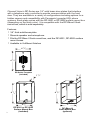
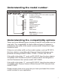
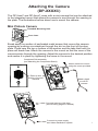
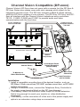
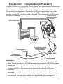
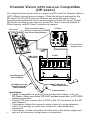
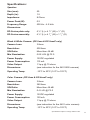
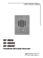
DP-XXXX
DP-XXXXC
DP-XXXXP
Telephone Entry Door Intercom
7
Channel Vision’s DP-Series are 1/4" solid brass door plates that interface
with a telephone entry controller to provide communication with the front
door. They are available in a variety of configurations including options for a
hidden camera and compatibility with Panasonic’s popular KSU phone
systems. Each plate comes with the DP-9001 or DP-9002 surface mount box
(depending on the finish color). It is compatible with the DP-Rbox-II flush
mount box, which is sold separately.
Features:
h 1/4” thick solid brass plate
h Discrete speaker and microphone
h Fits the DP-Rbox-II flush mount box, and the DP-9001, DP-9002 surface
mount boxes.
h Available in 8 different finishes
3
4 /8”
6 7/16”
DP-Series Faceplate
(included)
3 1/4”
6 1/8”
6 7/16”
4 3/8”
2
1 3/4”
DP-9001 or DP-9002
Surface Mount Box
(included)
4”
DP-Rbox-II
Flush Mount Box
(optional)
Understanding the model number:
Part numbering: DP door plates
DP-0212C
(DP-0212C shown for example only)
Blank
C
P
P-0920, P-0921, & TE110/C-0920 compatible
P-0930 compatible
Panasonic compatible
212
222
232
242
252
262
272
282
302
White
Polished Brass
Antique Brass
Chrome
Oil Rubbed Bronze
Antique Copper
Satin Silver
Black
Satin Nickel
0
5
6
No camera
Black and white camera
Color camera
Understanding the compatibility options
There are three different types of systems that DP door plates can be
used with. The compatibility for these different types of systems is
indicated by the suffix of the model number which follows the 4-digit
numerical code.
If there is not a letter suffix on the model number, such as DP-0212,
that door plate is compatible with Channel Vision’s telephone entry
products including models P-0920, P-0921, C-0920, and TE110.
If the suffix is the letter “P”, such as DP-0212P, then the door plate is
compatible with Panasonic’s phone systems which are designed to
use the Panasonic door phone model: KXT-30865.
If the suffix is the letter “C”, such as DP-0212C, then the door plate is
compatible with Channel Vision’s Whole-House CAT5 Intercom Hub,
model P-0930.
Please double check to be sure that you have purchased the correct
model number for your application.
3
Attaching the Companion Board
(DP-XXXX and DP-XXXXP)
This door intercom product consists of two sub assemblies which must be
attached to each other before the final assembly can be installed. In this
guide the electronic sub assembly will be referred to as the “Companion
Board” and the mechanical assembly will be referred to as the “Door Plate.”
Review the following diagrams and assemble as shown.
Companion Board Connection Details
To Button
To Speaker
Microphone
Remove the plastic cap that covers the microphone compartment on the
door plate. Place the microphone in the compartment and replace the plastic
cap over the microphone. Note that the plastic cap will form a friction fit over
the top of the microphone wires holding them snug against the outer
compartment wall until they exit at the base as shown. Remove the mounting
screws which are already attached to the bracket and use them to attach the
companion board. The companion board should mount on the front side of
the bracket so that the screws pass through the companion board before
threading into the bracket.
Companion Board
Place pressure cap
over microphone
Attach button
and speaker
wires as shown
Attach Companion Board
with mounting screws
Completed Sub-assembly
Connect Telephone Entry Controller here
(see following pages for details)
4
Attaching the Camera
(DP-XXXX and DP-XXXXP)
The DP-5xxx, DP-5xxxP, DP-6xxx, and DP-6xxxP come with a mini camera
that can be attached to the integrated mount that allows the camera to see
through the opening in the plate. The illustrations bellow show how to mount
the camera.
Mini Pinhole Camera
Threaded Mounting Hole
Cone Lens
Break away the section of perforated metal screen that covers the camera
opening by pushing a screwdriver through the slot on the front of the door
plate. Press near the top or bottom of the section and the tabs that hold it in
place will break free. Attach the camera to the mount so that the cone of the
camera points through the opening. Adjust the camera to the desired position
and secure it in place by tightening the screw in the mount.
Completed Sub-assembly
(see Attaching the Companion Board)
Attach camera to mount
using the screw provided
Remove this
section of screen
material
Attach pigtail
to rear of
camera
Connect Telephone Entry Controller here
(see following pages for details)
Connect to power supply
and video distribution system
5
Attaching the Companion Board
(DP-XXXXC)
This door intercom product consists of two sub assemblies which must be
attached to each other before the final assembly can be installed. In this
guide the electronic sub assembly will be referred to as the “Companion
Board” and the mechanical assembly will be referred to as the “Door Plate.”
Review the following diagrams and assemble as shown.
Companion Board Connection Details
Connection for
ST-C5IDS
Volume Adj.
To
Speaker
Jumper
(see chart)
To Button
Microphone
(attached to back side)
Jumper Chart
Function
Setting
D1
Door 1
D2
Door 2
Patio Mode
(No Jumper)
Position the companion board onto the three mounting tabs as shown below.
The microphone attached to the back side of the companion board should
line up with the microphone tube on the bracket. Bend the mounting tabs to
secure the companion board. Connect the speaker and button wires by
sliding the small connector over the exposed pins on the companion board
as shown.
Microphone
Tube
Companion Board
Attach button
and speaker
wires as shown
Align holes with
mounting tabs
Completed Sub-assembly
Bend mounting tabs
over to secure the
Companion Board
Connect Intercom Hub here
(see following pages for details)
Patio Mode:
If the button is pressed on another DP station configured
as Door 1 or Door 2, pressing the button on a DP station
set in Patio mode will answer the door station that just rang.
Press and release a second time to hang up, or press and
hold for 3 seconds to activate the ST-C5IDS Door Strike
Relay.
6
If neither Door 1 or Door 2 have been activated in the last
20 seconds, pressing the button on a DP station set in Patio
mode will page the house stations. Pressing the button a
second time will end the page.
Attaching the Camera
(DP-XXXXC)
The DP-5xxxC and DP-6xxxC come with a mini camera that can be attached
to the integrated mount that allows the camera to see through the opening in
the plate. The illustrations bellow show how to mount the camera.
Mini Pinhole Camera
Threaded Mounting Hole
Cone Lens
Break away the section of perforated metal screen that covers the camera
opening by pushing a screwdriver through the slot on the front of the door
plate. Press near the top or bottom of the section and the tabs that hold it in
place will break free. Attach the camera to the mount so that the cone of the
camera points through the opening. Adjust the camera to the desired position
and secure it in place by tightening the screw in the mount.
Completed Sub-assembly
(see Attaching the Companion Board)
Attach camera to mount
using the screw provided
Remove this
section of screen
material
Attach pigtail
to rear of
camera
Connect Intercom Hub here
(see following pages for details)
Connect to power supply
and video distribution system
7
Channel Vision Compatible (DP-xxxx)
Channel Vision’s DP-0xxx does not come with a camera, but the DP-5xxx &
DP-6xxx Series door plates come with mini cameras which attach to the
integrated camera mount. The DP-5xxx contains a Black & White camera,
while the DP-6xxx contains a color camera. The DP-0xxx, DP-5xxx, and DP6xxx all interface with the Channel Vision’s telephone entry controllers:
TE110, C-0920, P-0920 and P-0921 to provide audio and video
communication with the front door.
Connect to the
terminals marked
“TO SYS”
From Telephone
Service Provider
12VAC
500mA
CO Input
Chime
Unlock
Door
Intercom
Power
Phones
Ring
12VAC
Strike
Active
*
or #
No CO
3/5 rng
1
2
3
Intercom
Active
Strike
Time
Model
P-0920
PRO
CHANNEL
V ISION
TM
TELEPHONE ENTRY CONTROLLER
Telephones
CO Input
Camera Power
To Monitor or
Video Distribution
House
Telephones
2-Conductor Power
Supply Extension
(not included)
BNC Video
Connector
Coax Extension
(not included)
8
Installation:
h Install a compatible mounting box at the desired location, such as:
DP-Rbox-II flush mount box, DP-9001 surface mount box, or DP-9002
surface mount box.
h Using a 2-conductor wire, connect the Telephone Entry Controller to
the empty screw terminal block on the DP (see diagram).
h If necessary, attach the camera’s video output to a coax extension
that is long enough to reach your monitor or video distribution
equipment.
h If necessary, cut the connector off of the end of the power supply and
splice in an extension using crimp-on connectors.
Panasonic® Compatible (DP-xxxxP)
Channel Vision's DP Panasonic Series models are a compatible replacement
for the Panasonic KXT30865. These 1/4" solid brass door plates provide an
attractive alternative to the standard plastic door station sold by Panasonic.
This product interfaces with Panasonic’s KSU phone systems to provide
communication with the front door. Model DP-6xxxP includes a color
camera, model DP-5xxxP includes a Black & White camera, and DP-0xxxP
Connect to the
includes no camera.
terminals marked
“TO SYS”
From Telephone
Service Provider
Panasonic
KSU
System Phones
Camera Power
To Monitor or
Video Distribution
2-Conductor power
Supply Extension
(not included)
BNC Video
Connector
Coax Extension
(not included)
Installation:
h Install a compatible mounting box at the desired location, such as: DPRbox-II flush mount box, DP-9001surface mount box, or DP-9002 surface
mount box.
h Using a 2-conductor wire, connect the door phone output of your
Panasonic KSU to the empty screw terminal block on the DP (see
diagram).
h Consult your Panasonic manual for instructions regarding door phone
operation.
h If necessary, attach the camera’s video output to a coax extension that is
long enough to reach your monitor or video distribution equipment.
h If necessary, cut the connector off of the end of the power supply and
splice in an extension using crimp-on connectors.
9
Channel Vision CAT5 Intercom Compatible
(DP-xxxxC)
The diagram below shows how to connect the DP-xxxxC to Channel Vision’s
CAT5 Whole-House Intercom system. When the button is pressed on the
DP-xxxxC the ST-2000 Intercom Stations will generate a door chime.
Pressing Answer/End will open communication with the DP-xxxxC. Model
DP-6xxxC includes a color camera, model DP-5xxxC includes a Black &
White camera, and DP-0xxxC includes no camera.
DP-xxxxC
These terminals can be
used to connect a ST-C5IDS
Door Strike Relay Module
ST-2000
Room 1
Room 2
Room 3
Room 4
Page
Monitor
Room 5
DND
Answer/End
Room 6
Press here to
answer door
500ft.
max
P-0930
BNC Video
Connector
Hub
Link
In
A
B
C
D
Room 1
Model
P-0930
Room 2
Room 4
Room 3
PRO
CHANNEL
V ISION
TM
Room 5
Link
Out
Room 6
Whole-House Intercom
Page Trigger
Coax Extension
(not included)
2-Conductor power
Supply Extension
(not included)
Page Out
IR
Power
Emitters
+15VDC
To Monitor or
Video Distribution
Camera Power
10
Installation:
h Install a compatible mounting box at the desired location, such as:
DP-Rbox-II flush mount box, DP-9001 surface mount box, or DP-9002
surface mount box.
h Using CAT5 wire, connect the P-0930 to the 110 connector on the DP
(see diagram).
h If necessary, attach the camera’s video output to a coax extension
that is long enough to reach your monitor or video distribution
equipment.
h If necessary, cut the connector off of the end of the power supply and
splice in an extension using crimp-on connectors.
Specifications:
Speaker:
Size (mm):
50
Depth (in):
1.5
Impedance:
8 Ohms
Power Peak (W):
0.2
Frequency Range:
500 Hz - 4.5 kHz
Dimensions:
DP-Series plate only:
6 ½” (L) x 4 3/8” (W) x 1/4” (D)
DP-Series assembly:
6 ½” (L) x 4 3/8” (W) x 1 3/4” (D)
Black & White Camera: (DP-5xxx & DP-5xxxP only)
Camera Lens:
3.8mm
Resolution:
500 lines
S/N Ratio:
More than 48 dB
Min Illumination:
0.05 LUX @ F2.0
Power Supply:
12VDC regulated
Power Consumption:
110 mA
Video Output:
1 Vp-p @ 75 ohms
Dimensions:
(see instruction for the 5401 B/W camera)
Operating Temp:
-10°C to 50°C (14°F to 122°F)
Color Camera: (DP-6xxx & DP-6xxxP only)
Camera Lens:
3.8mm
Resolution:
380 lines
S/N Ratio:
More than 48 dB
Min Illumination:
0.4 LUX @ F2.0
Power Supply:
12VDC regulated
Power Consumption:
120 mA
Video Output:
1 Vp-p @ 75 ohms
Dimensions:
(see instruction for the 6401 color camera)
Operating Temp:
-10°C to 50°C (14°F to 122°F)
Specifications subject to change without notice.
11
Channel Vision Technology will repair or replace any defect in
material or workmanship which occurs during normal use of this
product with new or rebuilt parts, free of charge in the USA, for two
years from the date of original purchase. This is a no hassle warranty
with no mail in warranty card needed. This warranty does not cover
damages in shipment, failures caused by other products not supplied
by Channel Vision Technology, or failures due to accident, misuse,
abuse, or alteration of the equipment. This warranty is extended only
to the original purchaser, and a purchase receipt, invoice, or other
proof of original purchase date will be required before warranty
repairs are provided.
Mail in service can be obtained during the warranty period by calling
(800) 840-0288 toll free. A Return Authorization number must be
obtained in advance and can be marked on the outside of the shipping
carton.
This warranty gives you specific legal rights and you may have other
rights (which vary from state to state). If a problem with this product
develops during or after the warranty period, please contact Channel
Vision Technology, your dealer or any factory-authorized service
center.
www.channelvision.com
234 Fischer Avenue, Costa Mesa, California 92626 USA
(714)424-6500 (800)840-0288 (714)424-6510 fax
email: [email protected]
500-126 Rev C