1
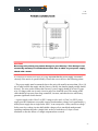
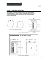
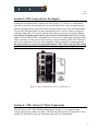
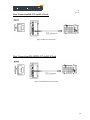
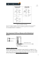
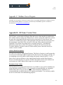
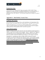
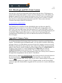
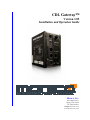
CDL Gateway™
Version 1.05
Installation and Operation Guide
MONICO, INC.
3403 Chapel Square
Spring, Texas 77388
Tel: (281) 350-8751
[email protected]
www.MONICOINC.com
v1.05
6.26.09
Table of Contents
Introduction ............................................................................................................................................................ 3
Section 1: Power Supply ........................................................................................................................................ 4
Section 2: Hardware Installation ........................................................................................................................... 8
Section 3: CDL Connection.................................................................................................................................... 9
Section 4: CDL Gateway™ Host Connections...................................................................................................... 9
Section 5: Troubleshooting LED’s ...................................................................................................................... 12
Section 6: MonicoView Programmer and User Interface .................................................................................... 13
Section 7: Diagnostic and Event Codes ............................................................................................................... 22
Appendix A: CDL Gateway™-Modbus Version ................................................................................................ 28
Modbus Register Conversion Details ................................................................................................................... 29
Appendix B: CDL Gateway™-CCM Translator Modbus Version...................................................................... 36
Modbus Register Conversion Details ................................................................................................................... 36
Appendix C: Modbus Viewer Program ............................................................................................................... 43
Appendix D: GE Fanuc Version Notes ............................................................................................................... 43
Appendix E: Allen Bradley Version Notes ......................................................................................................... 44
Appendix F: Siemens Notes ................................................................................................................................. 46
-2-
v1.05
6.26.09
Introduction
The CDL Gateway™ is a completely new generation of communications interface from Monico. It does not
require any intermediary devices to communicate with all engines that utilize the Data Link for primary
communications. This includes the vast majority of industrial engines, marine engines, large construction and
mining equipment engines, and generator sets that use the ADEM II & ADEM III ECM’s, EIS, and AFR
controls. The CDL Gateway™ is NOT an engine controller and is only used for monitoring engine and
generator parameters.
Like our previous products, it will automatically interrogate the CDL and determine which controllers are
present on the network. It will then poll all possible parameters to determine which parameters are present on
that particular installation. All values are in pre-assigned registers to minimize setup time. It is our intention to
always provide a product that requires little or no setup to function in a wide variety of applications. However,
any of our programs are modifiable using MonicoView software which is available for download on our
website at www.monicoinc.com. Make sure to check the website for the latest software revisions before
installation. The major features are listed below:
•
•
•
•
•
•
•
•
•
The CDL Gateway™ is much faster than the CCM Translator, which is used only in conjunction with
the CCM Module
The CDL Gateway™-Modbus Version offers Modbus RTU over Serial RS-232 and RS-485 as well as
Modbus TCP/IP over Ethernet. All ports are available on the same unit
The CDL Gateway™ has a User Interface via a USB connection that allows you to configure the ports
and see exactly which parameters are responding on your installation.
The CDL Gateway™ has an integral 24 VDC Power Supply
The CDL Gateway™ is designed to be mounted on Din-Rails, so no adapters are needed
The CDL Gateway™ uses modular jacks for connections which minimizes wiring errors, especially
when using our optional factory cables
The CDL Gateway™ does not require complicated address offsets.
The CDL Gateway™ does not require complicated Enable/Disable Masks as all parameters are default
enabled. If necessary, the user can deactivate individual registers or ports via the User Interface, but
due to the drastic increase in speed it should not be necessary for monitoring purposes
The CDL Gateway™ allows for other host protocols such as BACnet and can push parameters directly
to Allen Bradley Data Registers or Controller Tags, GE Fanuc Analog Input Registers, and Siemens
Data Blocks via RS-232, RS-485, and Ethernet. Special instructions for these versions are covered in
the appendix sections of this manual.
As always, you can count on Monico’s “No Questions Asked” support policy. We are committed to timely
support of every customer who contacts us for help regardless of where the gateway was purchased. The only
thing that matters to Monico is a successful installation.
-3-
v1.05
6.26.09
Figure 1.0 Gateway Connections Overview
Section 1: Power Supply
The CDL Gateway™ requires regulated 24 Vdc +/- 10% with 1000 ma power maximum.
Must use Class 2 or SELV rated power supply. You may use either an Isolated power
supply, or the properly grounded engine batteries to power the Gateway. If using an
isolated power supply, make sure to use CDL Monitor 2.0. If power is applied, the green
STS light will function. If this light is blinking, then no setup file is installed or it is
currently loading a file. If this light is solid, then a setup file is resident and operating.
-4-
v1.05
6.26.09
CAUTION
Reversing wire polarity may cause damage to your Gateway. This damage is not
covered by warranty. If in doubt about which wire is which on your power supply,
check with a meter.
If you must use an external power supply, it is very important that the power supply is mounted
correctly if the unit is to operate reliably. Please take care to observe the following points:
– The power supply must be mounted close to the unit, with usually not more than 6 feet (1.8
m) of cable between the supply and the Gateway. Ideally, the shortest length possible should
be used. The wire used to connect the Gateway’s power supply should be at least 22-gage
wire. If a longer cable run is used, a heavier gage wire should be used. The routing of the
cable should be kept away from large contactors, inverters, and other devices which may
generate significant electrical noise.
– A power supply with a Class 2 or SELV rating is to be used. A Class 2 or SELV power
supply provides isolation to accessible circuits from hazardous voltage levels generated by a
mains power supply due to single faults. SELV is an acronym for “safety extra-low voltage.”
Safety extra low voltage circuits shall exhibit voltages safe to touch both under normal
operating conditions and after a single fault, such as a breakdown of a layer of basic
insulation or after the failure of a single component has occurred.
-5-
v1.05
6.26.09
EMC INSTALLATION GUIDELINES
Although the CDL Gateway™ is designed with a high degree of immunity to Electromagnetic Interference
(EMI), proper installation and wiring methods must be followed to ensure compatibility in each application.
The type of electrical noise, source or coupling method into a unit may be different for various installations.
Cable length, routing, and shield termination are very important and can mean the difference between a
successful or troublesome installation. Listed are some EMI guidelines for a successful installation in an
industrial environment.
1. To reduce the chance of noise spikes entering the unit via the power lines, connections should be made to a
clean source. Connecting to circuits that also power loads such as contactors, relays, motors, solenoids etc.
should be avoided.
2. The unit should be mounted in a metal enclosure, which is properly connected to protective earth.
3. Use shielded (screened) cables for all Signal and Control inputs. The shield (screen) pigtail connection should
be made as short as possible. The connection point for the shield depends somewhat upon the application.
Listed below are the recommended methods of connecting the shield, in order of their effectiveness.
a. Connect the shield to earth ground (protective earth) at one end where the unit is mounted.
b. Connect the shield to earth ground at both ends of the cable, usually when the noise source
frequency is over 1 MHz.
c. Connect the shield to common of the Data Station and leave the other end of the shield unconnected
and insulated from earth ground.
4. Never run Signal or Control cables in the same conduit or raceway with AC power lines, conductors feeding
motors, solenoids, SCR controls, and heaters, etc. The cables should be run through metal conduit that is
properly grounded. This is especially useful in applications where cable runs are long and portable two-way
radios are used in close proximity or if the installation is near a commercial radio transmitter. Also, Signal or
Control cables within an enclosure should be routed as far away as possible from contactors, control relays,
transformers, and other noisy components.
5. Long cable runs are more susceptible to EMI pickup than short cable runs. Therefore, keep cable runs as
short as possible.
6. In extremely high EMI environments, the use of external EMI suppression devices is effective. The following
EMI suppression devices (or equivalent) are recommended:
Ferrite Suppression Cores for signal and control cables:
Fair-Rite part number 0443167251 (RLC part number FCOR0000)
TDK part number ZCAT3035-1330A
Steward part number 28B2029-0A0
Line Filters for input power cables:
Schaffner part number FN610-1/07 (RLC part number LFIL0000)
Schaffner part number FN670-1.8/07
Corcom part number 1 VR3
SPECIFICATIONS
1. POWER: 24 VDC ± 10%
200 mA min., without expansion card
1 Amp maximum with expansion card fitted
Must use Class 2 or SELV rated power supply.
2. COMMUNICATIONS:
USB/PG Port: Adheres to USB specification 1.1. Device only using Type B
connection.
Serial Ports: Format and Baud Rates for each port are individually software
programmable up to 115,200 baud.
RS232/PG Port: RS232 port via RJ12
COMMS Ports: RS422/485 port via RJ45, and RS232 port via RJ12
DH485 TXEN: Transmit enable; open collector, VOH = 15 VDC,
VOL = 0.5 V @ 25 mA max.
Ethernet Port: 10 BASE-T / 100 BASE-TX
RJ45 jack is wired as a NIC (Network Interface Card).
3. LEDs:
STS – Status LED indicates condition of Data Station.
TX/RX – Transmit/Receive LEDs show serial activity.
Ethernet – Link and activity LEDs.
-6-
v1.05
6.26.09
CF – CompactFlash LED indicates card status and read/write activity
4. MEMORY:
On-board User Memory: 4 Mbytes of non-volatile Flash memory.
On-board SDRAM:
DSPSX: 2 Mbytes
DSPGT: 8 Mbytes
Memory Card: CompactFlash Type II slot for Type I and Type II cards.
5. REAL-TIME CLOCK: Typical accuracy is less than one minute per month
drift. Crimson 2.0’s SNTP facility allows synchronization with external servers.
Battery: Lithium Coin Cell. Typical lifetime of 10 years at 25 ºC.
A “Battery Low” system variable is available so that the programmer can
choose specific action(s) to occur when the battery voltage drops below
its nominal voltage.
6. ENVIRONMENTAL CONDITIONS:
Operating Temperature Range: 0 to 50°C
Storage Temperature Range: -30 to +70°C
Operating and Storage Humidity: 80% max relative humidity,
non-condensing, from 0 to 50°C
Vibration According to IEC 68-2-6: 5 to 150 Hz, in X, Y, Z direction for 1.5
hours, 2 g’s.
Shock According to IEC 68-2-27: Operational 30 g, 11 msec in 3 directions.
Altitude: Up to 2000 meters
7. CONSTRUCTION: Case body is burgundy high impact plastic and
stainless steel. Installation Category I, Pollution Degree 2.
8. POWER CONNECTION: Removable wire clamp screw terminal block.
Wire Gage Capacity: 24 AWG to 12 AWG
Torque: 4.45 to 5.34 in/lb (0.5 to 0.6 N-m)
9. MOUNTING: Snaps onto standard DIN style top hat (T) profile mounting
rails according to EN50022 -35 x 7.5 and -35 x 15.
10. CERTIFICATIONS AND COMPLIANCES:
SAFETY
C-UL Class I Division II Groups A-D Approved for Hazardous Locations
UL Listed, File #E317425, ANSI/ISA12.12.01-2007, CSA22.2 No. 213-M1987
LISTED by Und. Lab. Inc. to U.S. and Canadian safety standards
UL Listed, File #E302106, UL508, CSA 22.2 No. 14-M05
LISTED by Und. Lab. Inc. to U.S. and Canadian safety standards
IEC 61010-1, EN 61010-1: Safety requirements for electrical equipment for
measurement, control, and laboratory use, Part 1.
ELECTROMAGNETIC COMPATIBILITY
Emissions and Immunity to EN 61326: Electrical Equipment for
Measurement, Control and Laboratory use.
Notes:
1. Criterion A: Normal operation within specified limits.
2. This device was designed for installation in an enclosure. To avoid
electrostatic discharge to the unit in environments with static levels above
4 kV precautions should be taken when the device is mounted outside an
enclosure. When working in an enclosure (ex. making adjustments, setting
jumpers etc.) typical anti-static precautions should be observed before
touching the unit.
11. WEIGHT: 15.1 oz (456.4 g)
Immunity to Industrial Locations:
Electrostatic discharge EN 61000-4-2 Criterion A 2
4 kV contact discharge
8 kV air discharge
Electromagnetic RF fields EN 61000-4-3 Criterion A
10 V/m
Fast transients (burst) EN 61000-4-4 Criterion A
2 kV power
2 kV signal
Surge EN 61000-4-5 Criterion A
1kV L-L,2 kV L&N-E power
RF conducted interference EN 61000-4-6 Criterion A
3 V/rms
Emissions:
Emissions EN 55011 Class A
-7-
v1.05
6.26.09
Section 2: Hardware Installation
DIN rail should be mounted horizontally so that the unit’s ventilation holes
are vertical in relation to cabinet orientation. A minimum clearance of 1 inch
(25.4 mm) should be maintained above and below the unit in order to ensure
proper thermal regulation.
Figure 2.1 Hardware Installation
Figure 2.2 Hardware Dimensions
-8-
v1.05
6.26.09
Section 3: CDL Connection to the Engine
Connection to the Data Link is via the RJ-45 Jack (Figure 3.1). The CDL is a differential
buss that is relatively noise immune, but care must be taken not to create ground loops and
good wiring practices are critical. This RJ-45 port has built-in receive (Rx-red) and transmit
(Tx-Green) LED lights which will show transmit and receive activity. If there is no action
with these lights after 5-10 seconds, then the Data Link is not active or not present. Please
note that the Caterpillar panel must be powered on for the data link to be active. If the Rx
light is on solid, then the CDL connections are reversed or the cable length is too long. If the
cable is too long, you may need to add a resistor across the terminals on the CDL Gateway™
side of the connection to lower the cable impedance. Before trying this, consult the factory.
Be sure the Gateway is powered using and isolated 24 VDC source and the EMC wiring
guidelines listed in Section 1 are followed or the properly grounded engine batteries.
Figure 3.1 CDL Connection Pin #7=CDL (+); Pin#8=CDL (-)
Section 4: CDL Gateway™ Host Connections
The Host device (PLC, HMI, Building Management System, etc.) is connected to the
Gateway through one of three host ports. The Gateway offers one RS 232 port (RJ-11 Jack);
one RS-485 port (RJ-45 Jack) and one Ethernet Port (RJ-45 Jack-Shielded).
-9-
v1.05
6.26.09
Host Connection-RS-232 via RJ-11 Jack
Figure 4.2 RS-232 Connections
Host Connections-RS-485/RS-422 via RJ-45 Jack
Figure 4.3 RS-485/RS-422 Connections
- 10 -
v1.05
6.26.09
Figure 4.3 RS-485/RS-422 Schematic
Please note that different companies use different terminology. For example, some use TxA and TxB to
describe 2- wire RS-485 connections. Some use Tx+ and Tx-. In general. TxA=Tx- and TxB=Tx+
For 2-wire RS-485, use Pin#7 = (+) and Pin#8 = (-).
Host Connections-TCP/IP over Ethernet via RJ-45 Shielded Jack
Ethernet
Figure 4.4 Ethernet Connections
ETHERNET COMMUNICATIONS
Ethernet communications can be established at either 10 BASE-T or 100 BASE-TX. The
Gateway’s RJ45 jack (Figure 4.4) is wired as a NIC (Network Interface Card). For example,
when wiring to a hub or switch use a straight-through cable, but when connecting to another
NIC use a crossover cable. Default IP Address is 192.168.1.10
- 11 -
v1.05
6.26.09
Section 5: Troubleshooting LED’s
STS – STATUS LED
The green Status LED provides information regarding the state of the Gateway. This includes
indication of the various stages of the start-up routine (power-up), and any errors that may
occur.
Startup Routine
LED
Rapidly Flashing
Steady
Indication
Gateway is currently loading program
Gateway is operating normally
Table 5.1 STS LED
SERIAL HOST PORTS - TX/RX LED’S
LED
Green
Red
Indication
Transmitting
Receiving
Table 5.2 Serial Host Port LED’s
CDL PORT - TX/RX LED’S
LED
Green
Red
Indication
Transmitting
Receiving
Table 5.3 CDL Port LED’s
TCP/IP ETHERNET PORT LED’S
LED
Yellow (Solid)
Yellow (Flashing)
Green
Amber
Indication
Link Established
Network Activity
10 BASE-T Communications
100 BASE-T Communications
Table 5.4 Ethernet Port LED’s
These LED’s are the first step in troubleshooting communications issues. Please note
the action of these LED’s, IN DETAIL, when contacting the factory for technical
support.
- 12 -
v1.05
6.26.09
Section 6: MonicoView Programmer
The MonicoView Programmer is a critical part of the product. This free software is used to
develop programs or modify files supplied from the factory to meet your needs. Please check
on our website for the latest version at www.monicoinc.com. MonicoView is used to adjust
port settings for each available port, to disable unused ports to maximize performance, to
delete unused or unavailable parameters from polling blocks, and to view live data for all
data blocks. MonicoView can also be used to modify any section of the unit programming.
However, make sure to use LINK-EXTRACT to save a copy of the original .mvd program
before making changes. If you click on the UPDATE button before OPENING a valid file
or EXTRACTING the existing file, it will result in a blank file being downloaded to the
Gateway which will render it ineffective. If this should occur, contact the factory and we can
email a copy of the file supplied with the Gateway. Please make note of the Version Number
on the label on the right side of the Gateway, so we can identify the appropriate file.
When upgrading MonicoView Programmers versions, us the REPAIR option.
The connection is established through a standard USB device cable that has the rectangular
connector on one end and the square connector with two rounded edges on the other. Make
sure to click on LINK-OPTIONS and set the connection to USB.
Installing USB Drivers
In some cases, connecting a laptop to AC can cause electrical grounding issues. In some
situations, a grounded AC supply on a laptop can cause intermittent errors with the laptop
USB port. Each time you connect, using the MonicoView Software, to a new CDL Gateway
unit, you will see the Windows “Found New Hardware” screen. Make sure to plug in the
USB Cable when the Gateway is powered down. Upon power up, it will then ask for both
required drivers to be installed at once.
First Installation
The first installation of the USB drivers from a specific computer will have to be done
manually. After this first installation on a given PC, it will know where to look for the
appropriate files. When asked to go to Windows Update to find a driver, select “No, not at
this time” and click “Next”. This will bring up the screen shown in Figure 6.1 below and the
“Install Automatically” should be selected by default. INSTEAD, choose Install From List
or Specific Location, click NEXT and use the Browse button to select the following location:
C:\Program Files\Monico\Monicoview\Device
Click Next and follow the instructions below to finish the process. From this point on, you
can use the Automatic Install option which is much simpler.
- 13 -
v1.05
6.26.09
Subsequent Installations
When asked to go to Windows Update to find a driver, select “No, not at this time” and click
“Next”. This will bring up the screen shown in Figure 6.1 below and the “Install
Automatically” should be selected by default. If your first installation is not successful, you
will need to follow the instructions at the end of this section to navigate to Device Manager
and perform a manual install.
Figure 6.1: USB Driver Automatic Installation
After this screen you will see the screen below stating that the driver you are installing has
not been tested by Microsoft. Select “Continue Anyway”.
Figure 6.2: Windows Compatibility Warning
- 14 -
v1.05
6.26.09
Click “Finish” when this screen is done. There is another driver that will need to be loaded,
but it will not be found until you download the program to the CDL Gateway™. After the
initial installation or update of the CDL Gateway™ program, Microsoft will find new
hardware again and you will go through the same process again, but instead of calling it “G3
Loader”, it will be called “G3 HMI”.
NOTE: If your Operating System does not successfully install the drivers, you will need to
perform this function manually. Go to Start and right-click on My Computer and choose
Manage. Then click on Device Manager and look for any yellow “!” beside any USB
Devices. Right-click on the item and select Update Driver. Select Manual Installation this
time and when you are asked to specify the location of the drivers, you will choose
C:\Program Files\Monico\Monicoview\Device where the drive letter is the drive you
selected when installing the software. This should correct the problem and this issue should
not happen again. This only seems to happen the first time Windows attempts to install the
first USB driver on a new PC. If this problem occurs, it is probably because of laptop USB
port issues. Therefore, before following these instructions, disconnect the Gateway from
the USB port, disconnect the laptop from AC Power, reboot the PC, and power cycle the
Gateway.
Enabling TCP/IP Download
Any function accomplished through the USB port can also be performed over
an Ethernet Network with the exception of Firmware Upgrades. A compact
Flash card installed in the Gateway is required to Upgrade Firmware over
TCP/IP. However, you must first use the USB connections to enable “IP
DOWNLOAD” under the REMOTE UPDATE section of the Ethernet port.
Then you must go to LINK-OPTIONS and choose TCP/IP and enter the IP
address of the CDL Gateway™. From this point you can perform database
updates and port setting changes over the LAN.
Deleting Unwanted Parameters
When you expand a Block, you will see what parameters are assigned to each
register. You can delete any parameters you will not be using and this will
optimize the update rate on the CDL Link. Please keep in mind that the CDL
Gateway™ will normally update all the parameters present on an engine in
about 2-3 seconds, so for monitoring purposes there is usually no need to
optimize. However, if you highlight a register and press the delete button on
your keyboard it will remove this parameter. Make sure to save an original
copy of the program and make changes to the file using another name. After
making these changes, you must choose Link>Update to send the changes to
the CDL Gateway™. This is the case with any subsequent changes. Please note
that you will not be able to change the register locations using the User
- 15 -
v1.05
6.26.09
Interface. When you delete the parameter, you are only removing it from the
CDL communications.
Adjusting Port Settings
The CDL Gateway™ has several HOST PORTS including two RS-232 ports, an RS-485
port, and an Ethernet port. MonicoView can be used to adjust the settings for any of these
ports and to disable the ports that are not being used. For example, if you need to change the
port settings for the RS-232 port you would see:
Figure 6.3: Serial Port Communications Settings
To change any of the settings shown in Figure 6.3, highlight the value and enter the new
setting and press enter to record the change. If the value is in a drop down window, just
select the new settings. Notice that you can set a Drop Number. This allows you to use the
RS-232 port with a multi-drop network using RS-232 to RS-485 converters. Enter the Device
Address for the CDL Gateway™ (in the case of Slave protocols) in the Drop Number box
and press ENTER. If the port is setup as a Master Device, then the target drop number will be
entered.
- 16 -
v1.05
6.26.09
The only difference with the RS-485 port is choosing whether you want 2-wire RS-485 or 4wire RS-485 or RS-422. This screen is shown in Figure 6.4 below.
Figure 6.4: RS-485 Serial Port Settings
Settings for the Ethernet port are show in Figure 6.5 and include setting the Port Mode where
you set whether to Manually Configure the IP address, request an IP address from a DHCP
server or use IEEE 802.3. Then enter the IP address if manually configured and the
associated Network Mask and Gateway.
- 17 -
v1.05
6.26.09
Figure 6.5: TCP/IP Ethernet Port Settings
Disabling and Enabling Ports
The CDL Gateway™ is a standard product that ships pre-configured with all ports active and
populated with a full array of values. Since each port will have over 400 registers to update,
it is recommended that you disable the unused ports by selecting the port and unchecking the
box under Device Settings labeled ENABLE DEVICE as shown in Figure 6.6 below. By
disabling unused ports you will maximize the performance of the Gateway.
- 18 -
v1.05
6.26.09
Figure 6.6: Enable/Disable Ports
Viewing Live Data
MonicoView can also be used to view live data for each data block. Highlight an individual
data block and click the button labeled View Block. This will cause the software to connect
to the CDL Gateway™ and display the current data for each parameter.
Figure 6.7: View Data Blocks
- 19 -
v1.05
6.26.09
A table will appear that will show the data block, the parameter tag, and the value in that
register in both Decimal and Hexadecimal.
Figure 6.8: Live Block Viewer
Parameter Status Block
A special device named “PIDStatusValues” is usually installed under the Programming RS232 port. Blocks 1-4 contains registers showing internal details for each possible parameter.
These parameters are best viewed in Hex format. The left-hand character (XXxx) indicates
the current action in the driver. Consult the factory for details of this parameter if you are
experiencing difficulties. The right hand character (xxXX) indicates the controller which is
currently providing the parameter. PLEASE NOTE THIS DOES NOT NECESSARILY
MEAN YOU WILL HAVE A VALUE IN THE PARAMETER. It simply means that at least
one controller on the engine network is responding to the request for that specific parameter.
If you have any issues with a particular parameter, it is a good idea to record this status value
for use by the factory in troubleshooting. Any parameter with a value in the right-hand hex
character, should be available in your installation. However, if the appropriate sensor is
not actually installed, you may see a high or low range value.
This feature is critical to know what values are responding in a specific application. If
absolute minimum update times are required, you can use MonicoView to delete the
unavailable parameters, in the Host Devices, to keep scan times to the absolute minimum.
- 20 -
v1.05
6.26.09
Figure 6.9: Parameter Status Block
Raw Data Block
The second Device installed under the RS-232 Programming Device is called
“PIDRawValues”. Blocks 1-4 under this Device are setup to view raw values for
troubleshooting purposes. These values are the raw values read directly from the CDL Link
before any gain is applied or unit conversions are performed. Note that in most of the
Modbus Versions, this block is omitted because all values are raw. In the PLC versions, the
raw data is useful for troubleshooting conversion formulas and each section of the
communications network.
Installing Program Updates
If you are sent a program update from the factory, you will need to install it using
MonicoView. First install MonicoView, start the program, connect the CDL Gateway™ via
the USB port on the front. If this is the first time you have connected to this particular
gateway, you will need to install the USB Drivers as shown above. After the first driver
installation is finished, go to the file sent to you by the factory and double-click on it. This
- 21 -
v1.05
6.26.09
will automatically start MonicoView. Select “Link” and then “Send”. This will begin the
download process. During this installation, you will be asked to go through another USB
Driver installation as shown above. Then MonicoView will automatically finish loading the
upgraded program. REMEMBER, IF THIS IS THE FIRST USB DRIVER
INSTALLATION ON A PARTICULAR COMPUTER, YOU MUST USE THE
MANUAL INSTALLATION METHOD OUTLINED ABOVE.
CDL MONITOR 2.0
In build 444 and above, you will have the option to choose either CDL Monitor 1.0 or CDL
Monitor 2.0. CDL 2.0 is much faster than the old driver and automatically identifies more
engine module configurations without need for manual intervention. Also, this driver is so
fast that the NO RESPONSE DEFERRAL system used in 1.0 was no longer needed.
Therefore, data recover after loss of data link communication is only a few seconds using
CDL Monitor 2.0 instead of up to 10 minutes using CDL Monitor 1.0.
Data scan rates for all 408 potential parameters using CDL Monitor 2.0 have be measured at
.5-3 seconds. This performance is determined by network traffic and engine module
configuration, but in all cases the update rate is much improved with the new driver.
CAUTION: If you would like to convert your database to CDL Monitor 2.0, contact the
factory before attempting. In some cases, this change will invalidate any mappings
associated with the data link. However, the factory technical personnel can quickly modify
the database to avoid this problem. Simply email the .mvd file to [email protected]
and request the driver change.
Section 7: Diagnostic and Event Codes
The CDL Gateway™ now supports the Diagnostic and Event codes from the Data Link. To
activate support for Diagnostic and Event codes, double-click on the COMMUNICATIONS
tab and click on COLLECT FAULT DATA as shown in figure 7.1 below.
- 22 -
v1.05
6.26.09
Figure 7.1 Collect Fault Data
If only COLLECT FAULT DATA is checked, it will cause the following fault data to be
collected:
MID-Module Identifier of the diagnosing controller
CID-Component Identifier of the fault device
FMI or SubCode-Fault Mode Identifier showing the severity of the fault
Flags-Indicates whether the codes is Event or Diagnostic Code and whether it is
Active or not
If FETCH FAULT DETAILS is also checked, the driver will also collect the following
information for each fault code:
OCCURENCES-Number of times this code has occurred
FIRST-First occurrence in engine operating hours
LAST-Last occurrence in engine operating hours
In figure 7.2 below, you can see a block of fault data collected without Fault Details and
mapped to Allen Bradley Tag Names, as an example. As you can see in this figure:
Faultsource=MID
Faultcode=CID
Faultsubcode=FMI or Sub-Code
FaultFlags=Shows whether it is a Diagnostic Code or Event Code (Bit7) and whether
the code is currently ACTIVE (Bit0).
If Bit7 of this value is high, then it is a Diagnostic code. If low, then it is an Event.
- 23 -
v1.05
6.26.09
If Bit 0 of this value is high, then the code is currently ACTIVE. If low, then it is
inactive.
Figure 7.2 FaultCode Data Block
Figure 7.3 below shows a data block example with the Details Fault information
where:
FaultCount=Number of Occurrences of this specific Code
FaultFirst=First Occurrence in Engine Operating Hours
FaultLast=Last Occurrence in Engine Operating Hours
The example in Figure 7.3 will result in detailed fault and event codes information for
the most recent five fault codes as sorted by Last Occurrence. If more than the last 25
codes are desired, the list is easily expanded.
- 24 -
v1.05
6.26.09
Figure 7.3 Details Fault Code Block Example
Creating Fault Blocks
The pre-configured factory programs do not usually contain fault blocks because it
takes up resources and is not required in the majority of applications. Creating custom
Fault Blocks is easily accomplished using MonicoView Programmer using the
following instructions:
- 25 -
v1.05
6.26.09
1. After highlighting the desired device, click on Add Gateway Block. Then
highlight the Gateway Block and Click EDIT under the Starting Address
section. Choose the appropriate starting address.
2. Then click EDIT under Block Size to choose the total number of registers you
want to use for fault codes. So, for five codes using all details you will need
35 registers.
3. Highlight the first register and double-click on FaultSource on the right-hand
side of the screen. The resulting screen will be shown in Figure 7.4.
4. Click OK and then it will ask you how many you want to create. This screen
is shown in figure 7.5. If you want to capture the last five fault codes, then
enter five. If you want the last 25 fault codes, then enter 25.
5. Repeat 1-4 to map registers for each code you wish to capture.
Figure 7.4 Fault Block Creation Example
- 26 -
v1.05
6.26.09
Figure 7.5 Number of Registers to Map Screen
- 27 -
v1.05
6.26.09
Appendix A: CDL Gateway™-Modbus Version
Modbus Version Overview
The Standard Modbus Version offers three host ports in slave mode. They are:
• Modbus RTU Slave over RS-232 via the RJ-11 jack
• Modbus RTU Slave over RS-485 (2-wire or 4-wire) via RJ-45 jack
• Modbus TCP/IP Slave over Ethernet via RJ-45 jack
Other Modbus versions are available upon request such as a Modbus Master version. One
such scenario would be if you had several Modbus RTU Slave devices in the field and want
to aggregate them into a single Modbus Data Map. In this case, we can setup the RS-485 to
be a Modbus Master to poll the slave devices and map all the registers to the RS-232 or
Ethernet port which would be setup as a Modbus Slave. The CDL Gateway™ can also mix
Modbus with other protocols such as BACnet and data maps for most of the popular PLC
manufacturers. One popular scenario is to use the CDL Gateway™ as a Modbus master to
poll several slave devices on RS-485, bring in the engine data, and combine all parameters
into a single data map that is compatible with an Allen Bradley, GE Fanuc, or Siemens PLC.
Contact the factory to discuss your specific application.
Modbus Address Description
The CDL Gateway™-Modbus Version has a very simple, pre-assigned, address system that
starts at 30001 and goes through 30429 for Modbus Function code “4” and 40001-40429 for
Modbus Function Code “3”. Currently, it is necessary to specify whether you will be
using Function Code “3” or “4”. Since this is primarily a monitoring device, our default
version uses Input Registers only The Modbus Data Map is available on the Downloads
page of the Monico, Inc. web site (www.monicoinc.com). The data map provides extensive
details needed for successful installation and operation of the Gateway. MAKE SURE YOU
HAVE THIS MANUAL AND THE MODBUS DATA MAP WHEN GOING INTO
THE FIELD TO INSTALL THE GATEWAY.
The same groups of addresses are assigned to all of the Host Ports. Therefore, you can poll
the same registers from either the RS-485 RJ-45 port, the RS-232 RJ-11 Port, or the Ethernet
RJ-45 port. IT IS HIGHLY RECOMMENDED TO DISABLE ANY UNUSED PORTS TO
OPTIMIZE GATEWAY PERFORMANCE.
There are other versions of this device that will simulate the same addresses as our Monico
CCM Translator, but that version needs to be specifically requested. We also offer versions
that utilize other protocols such as BACnet instead of Modbus. Other versions act as remote
devices for Allen Bradley Ethernet IP or GE Fanuc PLC’s, etc. If you are being forced to
convert Modbus into another format or protocol, please give Monico Technical Support a
call. We may be able to save you time and money.
- 28 -
v1.05
6.26.09
Modbus Register Conversion Details
All data is transmitted from the engine network in Metric Units. Therefore, some of the raw values from the
modbus registers will require calculations to convert them into actual engine data. Any unit conversion will
need to take place after the following instructions. The following information provides a list of the conversion
types and the calculations necessary to provide actual engine measurement values.
Hex to Integer
For signed values: Value should be read from the modbus registers as a signed integer. After being read,
multiply by the gain and add the offset.
For unsigned values: Value should be read from the modbus registers as an unsigned integer. After being read,
multiply by the gain and add the offset.
Engine Type Code as 3 Digit Integer
Format is XYY where X is the engine family and YY is the number of cylinders.
Negative=Active, Positive=Inactive
A value of 0 indicates that the status is inactive, disabled or off.
A value of 1 indicates that the status is active, enabled or on.
Diagnostic Codes
0=False (OFF), NonZero =True (ON) w/Fault Codes
A value of 0 indicates that the status is inactive, disabled or off.
A value of 1 indicates that the status is active, enabled or on.
0=Stop (OFF), NonZero=Start (ON)
A value of 0 indicates that the status is inactive, disabled or off.
A value of 1 indicates that the status is active, enabled or on.
Multistate
Read from modbus register as unsigned integer. The value is composed of more than one status condition. This
is accomplished by setting the appropriate bits for each status condition. See details below:
Monico PID Description
Id
Modbus Manual Remarks
Address
15
Engine Control Switch Position
30015
0=Off/reset, 2=Start, 3=Stop, 4=Auto
16
Shutdown Notify Relay Status
30016
0=Relay is OFF, 1=Relay is ON
19
Start-up Mode Status
30019
27
Engine Prelube Status
30027
30
Remote Throttle Override (Generator Set Only)
30030
32
Low Idle Switch Position
30032
0=Starter is OFF, 1=Starter is ON, 2=Overcrank, 3=Startup
Successful, 224-255 are Fault Identifiers*
Starting at 0: Prelube=OFF, ON, DISABLED,
COMPLETED. 4-255 are Fault Identifiers*
0= Normal throttle setting, 1=Low idle setting, 224-255 are
Fault Identifiers*
0=Switch is OFF, 1=Switch is ON, 224-255 are Fault
Identifiers*
- 29 -
v1.05
6.26.09
59
Generator Phase A Power Factor Lead/Lag Status
30059
0=Current lags voltage, 1=Current leads voltage, 224-255
Fault Identifiers*
0=Current lags voltage, 1=Current leads voltage, 224-255
Fault Identifiers*
0=Current lags voltage, 1=Current leads voltage, 224-255
Fault Identifiers*
0=Current lags voltage, 1=Current leads voltage, 224-255
Fault Identifiers*
0=Breaker open, 1=Breaker closed, 228=Breaker sensor input
shorted low
0=coolant pressure OK, 1=coolant pressure too high, 2=Too
Low. 0-223 is Valid Range, 224-255 are Fault Identifiers
60
Generator Phase B Power Factor Lead/Lag Status
30060
61
Generator Phase C Power Factor Lead/Lag Status
30061
62
Generator Average Power Factor Lead/Lag Status
30062
67
EPG Circuit Breaker Status (GSP+P only)
30067
151
Engine Coolant Pump Pressure Status
30151
200
Hydrax Oil Pressure Switch Status
30200
22=Open, 23=Closed. 65504-65535 are Fault Identifiers
202
Emissions Feedback Mode
30202
394=Combustion Time Feedback, 395=Exhaust Temperature
Feedback, 397=Calibration Feedback, 398=No Feedback,
65504-65535 are Fault Identifiers
Multistate
Read from modbus register as unsigned integer. The value indicates different status conditions depending on
the value being read. See details below:
Monico PID Description
Id
Modbus Manual Remarks
Address
22
Generator Phase Select
30022
0=Phase A-B Volts A current, 1=Phase B-C Volts B current,
2=Phase C-A Volts C current
0=700v, 1=150v, 2=300, 3=500, 4=600, 5=750, 6=3k,
7=4.5k, 8=5.25k, 9=9k, 10=15k, 11=18k, 12=30k
25
Generator AC Voltage Full Scale and External PT
Setpoint
30025
26
Generator AC Current Full Scale Setpoint (Read)
30026
31
ECM in Control (Marine Only)
30031
57
Generator AC Voltage Full Scale Transformer Setpoint
30057
0=700v, 1=150v, 2=300, 3=500, 4=600, 5=750, 6=3k,
7=4.5k, 8=5.25k, 9=9k, 10=15k, 11=18k, 12=30k
58
Generator AC Current Full Scale Setpoint
30058
68
Remote Generator Synchronizer Control (GSP+P only)
30068
69
Remote Synchronization Control Readiness (GSP+P
only)
30069
starting at 0:
75,100,150,200,300,400,600,800,1k,1.2k,1.5k,2k,2.5k,3k,4k
Amps
(This can be written to) 0=Off, 1=Remote synchronization
test, 2=Automatic synchronization
0=Not installed, 1=ready for remote command,
2=Synchronizing switch not in auto, 3=Engine control switch
not in auto, 4 Engine was not started remotely, 5 Engine not
running
70
Generator Synchronizer Control Status (GSP+P only)
30070
Starting at 0: Not installed, Inactive, Semiautomatic
paralleling, Permissive paralleling, Remote synchronization
testing, Synchronizing, Synchronization system alarm or
diag., Remote synchronization testing passed, Dead bus time
delay, Closing to dead bus.
201
Normal Stop Input Status
30201
113=Run, 174=Stop
starting at 0:
75,100,150,200,300,400,600,800,1k,1.2k,1.5k,2k,2.5k,3k,4k
Amps
0=Primary ECM is controlling, 1=Backup ECM is controlling
- 30 -
v1.05
6.26.09
Multiple Status Bits
Read from modbus register as unsigned integer. The value is composed of more than one status condition. This
is accomplished by setting the appropriate bits for each status condition. See details below:
Monico PID Description
Id
Modbus Manual Remarks
Address
6
Oxygen Sensor Status
30006
Bits set to 1 indicate Status: 8=start cal. 7= cal in progress,
6=sensor on, 5= command sensor on
Bits set to 1 indicate Status: 8=cal good else cal bad, 7=
enable cal else disable cal
Bit8: 0=idle, 1=rated. Bit7: 0=off grid, 1=on grid. Bit6-5:
00=running, 01=coasting, 10=shutdown, 11=not used
Bit8: 0=genset, 1=industrial. Bit6: 0=isochronous govenor,
1=droop govenor
Mode Control Switch Bit8-7: 11=start, 10=auto, 01=stop,
00=off/reset. E-Stop Bit6: 1=stop, 0=run. Driven
Equipment Bit5: 1=Ready, 0=Not Ready. Prelube Slave
Relay Bit4: 1=ON, 2=OFF. Prelube Relay Bit3: 1=ON,
2=OFF. Prelube Switch Bit2: 1=Not Ready, 0=Ready.
Initiate Contact Bit1: 1=Stop, 0=Run.
8
Ignition Timing Calibration
30008
40
G3600 Engine Status
30040
41
Engine Operation
30041
46
Auxiliary Status
30046
52
EIS Special Test Status
30052
56
Diagnostic Status Summary
30056
65
General Alarm Output Status/Override (Marine Only)
30065
77
Engine Status
30077
90
GSC Relay Status
30090
91
GSC Relay Control
30091
93
GSC Alarm Status
30093 Organized by bit pairs where for each pair 0=Alarm Off,
Inactive (Tests should only be done on-site) bit 8: 1=Enable
special test, 0=disable. Bit7: 0=proceed to test B. Bit5-1
0=test passed. Non zero=# of tests failed
Bits 2-1: 0=None, 1=Level 1 Warning, 2=Level2 Warning,
3=Level 3 Warning. Bit 3&4 not used. Bit 5: 0=No logged
events, 1=At least 1 logged event. Bit 6 not used. Bit7: 0=No
logged diag., 1=At least 1 logged diag. Bit8: 0=No active
diag. 1=At least 1 active diag.
(This can be written to) Bit 8: 1=Override, 0=Normal. Bit 1:
0=Output is OFF, 1=Output is ON
Bit 4: 1=Fuel injection disabled, 0=No injection disabled.
Bit5: 1=E-stop shutdown, 0=No E-stop shutdown. Bit 1:
1=No Engine Speed, 0=Engine Speed
Organized by bit pairs where for each pair 0=Off/deenergized, 1=On/energized, 3=Relay not installed: Bits 2,
1=Air Shutoff Relay. Bits 4,3=Fuel Control Relay. Bits
6,5=Crank Terminate Relay. Bits 8,7=Starter Motor Relay.
Bits 10,9=Genset Fault Relay. Bits 12,11=Run Relay. Bits
14,13=Program Spare Relay. Bits 16,15=Electronic Govenor
Relay.
(only bits 16-13 are write able) Organized by bit pairs where
for each pair 0=Off/de-energized, 1=On/energized, 3=Relay
not installed, keep same state: Bits 2,1=Air Shutoff Relay.
Bits 4,3=Fuel Control Relay. Bits 6,5=Crank Terminate
Relay. Bits 8,7=Starter Motor Relay. Bits 10,9=Genset Fault
Relay. Bits 12,11=Run Relay. Bits 14,13=Program Spare
Relay. Bits 16,15=Electronic Govenor Relay.
1=Alarm On, 3=Not Available: Bits 2,1=High Coolant Temp.
Bits 4,3=Low Coolant Temp. Bits 6,5=Low Oil Psi. Bits
8,7=Eng Control Switch not in Auto or Manual. Bits
10,9=High Oil Temp. Bits 12,11=Eng Control Alarm. Bits
14,13=Not used. Bits 16,15=Undefined.
- 31 -
v1.05
6.26.09
Monico PID Description
Id
Modbus Manual Remarks
Address
94
GSC Shutdown Status
30094
Organized by bit pairs where for each pair 0=Shutdown
Inactive, 1=Shutdown Active, 3=Not Available: Bits
2,1=Diag Code. Bits 4,3=Coolant Loss. Bits 6,5=Emg Stop.
Bits 8,7=Spare Fault. Bits 10,9=High Coolant Temp. Bits
12,11=Low Oil Psi. Bits 14,13=Overcrank. Bits
16,15=Overspeed.
95
GSC Spare Fault Alarm Status
30095
Organized by bit pairs where for each pair 0=Alarm Off,
1=Alarm On, 3=Not Available: Bits 2,1=Spare Fault 1. Bits
4,3=Spare Fault 2. Bits 6,5=Spare Fault 3. Bits 8,7=Spare
Fault 4. 16-9=Undefined.
96
GSC Spare Fault Shutdown Status
30096
Organized by bit pairs where for each pair 0=Shutdown
Inactive, 1=Shutdown Active, 3=Not Available: Bits
2,1=Spare Fault 1. Bits 4,3=Spare Fault 2. Bits 6,5=Spare
Fault 3. Bits 8,7=Spare Fault 4. 16-9=Undefined.
146
Generator Set Control Output Status (GSC+ only)
30149
Organized by bit pairs where for each pair 0=Off/deenergized, 1=On/energized, 2=Output Fault, 3=Output not
installed: Bits 2,1=Close Breaker Output. Bits 4,3=Kilowatt
Relay Control Output
112
Generator Set Shutdown Status - Extension #1
30112
Organized by bit pairs where for each pair 0=Shutdown
Inactive, 1=Shutdown Active, 3=Not Available: Bits
13,14=Engine Control Shutdown. Bits 15,16=High Engine
Oil Temp.
150
Active Warning Summary Status
30150
Bit 16=Warning Level 1, Bit 15=Warning Level 2, Bit
14=Warning Level 3 (bit value: 0=INACTIVE, 1=ACTIVE)
0=Enabled, NonZero=Disabled
A value of 0 indicates that the status is inactive, disabled or off.
A value of 1 indicates that the status is active, enabled or on.
0=Inactive, NonZero=Active
A value of 0 indicates that the status is inactive, disabled or off.
A value of 1 indicates that the status is active, enabled or on.
Hex to Long Integer
The value is contained in 2 consecutive modbus registers. For example, if the first value is at address 40001 the
value at 40002 will also need to be read.
Read each register as an unsigned integer. Take the first value and multiply by 65536. Then add the second
value. Multiply the result by the gain and add the offset.
Long Multiple Status Bits
The value is contained in 2 consecutive modbus registers. For example, if the first value is at address 30001 the
value at 30002 will also need to be read.
Read each register as an unsigned integer. Take the first value and multiply by 65536. Then add the second
value.
The result is composed of more than one status condition. This is accomplished by setting the appropriate bits
for each status condition. See details below:
- 32 -
v1.05
6.26.09
Monico PID Description
Id
Modbus Manual Remarks
Address
239
Warning Status
30239
240
Shutdown Status
30240
241
Engine Derate Status
30241
Each of the first 24 bits represents warning status.
0 = Warning is NOT ACTIVE
1 = Warning is ACTIVE
bit 1 = High exhaust temperature
bit 2 = High altitude (atmospheric pressure)
bit 3 = Air filter plugged
bit 4 = Engine overspeed
bit 5 = Low engine coolant temperature
bit 6 = High engine coolant temperature
bit 7 = Low engine oil pressure
bit 8 = High system voltage
bit 9 = High engine inlet air temperature
bit 10 = High engine oil temperature
bit 11 = High hydraulic oil temperature
bit 12 = No coolant flow
bit 13 = High aftercooler coolant temperature
bit 14 = High crankcase pressure
bit 15 = Fuel filter plugged
bit 16 = Oil filter plugged
bit 17 = Not used
bit 18 = Not used
bit 19 = Low coolant level
bit 20 = Alternator NOT charging
bit 21 = Low fuel level
bit 22 = High transmission oil pressure
bit 23 = Low transmission oil pressure
bit 24 = High transmission oil temperature
bit 25-32 = Not used
Each of the first 24 bits represents Shutdown status.
0 = Engine Shutdown is NOT ACTIVE
1 = Engine Shutdown is ACTIVE
bit 1 = High exhaust temperature
bit 2 = High altitude (atmospheric pressure)
bit 3 = Air filter plugged
bit 4 = Engine overspeed
bit 5 = Low engine coolant temperature
bit 6 = High engine coolant temperature
bit 7 = Low engine oil pressure
bit 8 = High system voltage
bit 9 = High engine inlet air temperature
bit 10 = High engine oil temperature
bit 11 = High hydraulic oil temperature
bit 12 = No coolant flow
bit 13 = High aftercooler coolant temperature
bit 14 = High crankcase pressure
bit 15 = Fuel filter plugged
bit 16 = Oil filter plugged
bit 17 = Not used
bit 18 = Not used
bit 19 = Low coolant level
bit 20 = Alternator NOT charging
bit 21 = Low fuel level
bit 22 = High transmission oil pressure
bit 23 = Low transmission oil pressure
bit 24 = High transmission oil temperature
bit 25-32 = Not used
Each of the first 24 bits represents Eng. Derate status. 0 =
Engine Derate is NOT ACTIVE
1 = Engine Derate is ACTIVE
bit 1 = High exhaust temperature
bit 2 = High altitude (atmospheric pressure)
bit 3 = Air filter plugged
bit 4 = Engine overspeed
- 33 -
v1.05
6.26.09
Monico PID Description
Id
Modbus Manual Remarks
Address
242
Spare Outputs (GSC+ only)
30242
244
Relay Driver Module Relay State
30244
258
Generator Shutdown Status (GSC+ only)
30258
259
Generator Alarm Status (GSC+ only)
30259
bit 5 = Low engine coolant temperature
bit 6 = High engine coolant temperature
bit 7 = Low engine oil pressure
bit 8 = High system voltage
bit 9 = High engine inlet air temperature
bit 10 = High engine oil temperature
bit 11 = High hydraulic oil temperature
bit 12 = No coolant flow
bit 13 = High aftercooler coolant temperature
bit 14 = High crankcase pressure
bit 15 = Fuel filter plugged
bit 16 = Oil filter plugged
bit 17 = Not used
bit 18 = Not used
bit 19 = Low coolant level
bit 20 = Alternator NOT charging
bit 21 = Low fuel level
bit 22 = High transmission oil pressure
bit 23 = Low transmission oil pressure
bit 24 = High transmission oil temperature
bit 25-32 = Not used
(writable) Bits 26-25 Spare Output, All other bit pairs are
undefined. 0=OFF, 1=ON, 16=Output Fault, 17=Output not
available
(writable) For each group of bits: 00 = OFF/DEENERGIZED; 01 = ON/ENERGIZED; 10 = Output fault; 11
= Output not available/ Don’t change state.
bits 1-2 = Undefined, future use
bits 3-4 = Undefined, future use
bits 5-6 = Undefined, future use
bits 7-8 = Undefined, future use
bits 9-10 = Output 9
bits 11-12 = Undefined, future use
bits 13-14 = Undefined, future use
bits 15-16 = Undefined, future use
bits 17-18 = Output 5
bits 19-20 = Output 6
bits 21-22 = Output 7
bits 23-24 = Output 8
bits 25-26 = Output 1
bits 27-28 = Output 2
bits 29-30 = Output 3
bits 31-32 = Output 4
For each group of bits: 00 = Shutdown inactive; 01 =
Shutdown active; 10 = Undefined; 11 = Not available, or not
installed.
bits 1-2 = Underfrequency
bits 3-4 = Overfrequency
bits 5-6 = Undervoltage
bits 7-8 = Overvoltage
bits 9-10 = Generator Frequency Sensing Fault
bits 11-12 = Generator Total Overcurrent
bits 13-14 = Single Phase Overcurrent
bits 15-16 = Reverse Power
bits 17-18 = Undefined, future use
bits 19-20 = Undefined, future use
bits 21-22 = Undefined, future use
bits 23-24 = Generator Freq. Inconsistent w/Eng Speed
bits 25-26 = Undefined, future use
bits 27-28 = Undefined, future use
bits 29-30 = Undefined, future use
bits 31-32 = Undefined, future use
For each group of bits: 00 = Alarm inactive; 01 = Alarm
- 34 -
v1.05
6.26.09
Monico PID Description
Id
Modbus Manual Remarks
Address
260
High Exhaust Port Temp Deviating Low Warning
30260
261
High Exhaust Port Temp Deviating Low Shutdown
30261
active; 10 = Undefined; 11 = Not available, or not installed.
bits 1-2 = Underfrequency
bits 3-4 = Overfrequency
bits 5-6 = Undervoltage
bits 7-8 = Overvoltage
bits 9-10 = Generator Frequency Sensing Fault
bits 11-12 = Generator Total Overcurrent
bits 13-14 = Single Phase Overcurrent
bits 15-16 = Reverse Power
bits 17-18 = Undefined, future use
bits 19-20 = Undefined, future use
bits 21-22 = Undefined, future use
bits 23-24 = Generator Freq. Inconsistent w/Eng Speed
bits 25-26 = Undefined, future use
bits 27-28 = Undefined, future use
bits 29-30 = Undefined, future use
bits 31-32 = Undefined, future use
Status indicated by bits. 0-4294967295 is Valid Range. Each
of the first 24 bits represents warning status.
0 = Warning is NOT ACTIVE
1 = Warning is ACTIVE
bit 1 = Exhaust Temperature Deviating Low
bit 2 = Exhaust Temperature Deviating High
Status indicated by bits.
0 = Shutdown is NOT ACTIVE
1 = Shutdown is ACTIVE
bit 1 = Exhaust Temperature Deviating Low
bit 2 = Exhaust Temperature Deviating High
- 35 -
v1.05
6.26.09
Appendix B: CDL Gateway™-CCM Translator Modbus Version
Modbus Address Description
The CDL Gateway™-Modbus Version has a very simple, pre-assigned, address system that
starts at 30001 and goes through 30429 for Modbus Function code “4” and 40001-40429 for
Modbus Function Code “3”. Currently, it is necessary to specify whether you will be
using Function Code “3” or “4”. The Modbus Data Map is available on the Downloads
page of the Monico, Inc. web site (www.monicoinc.com). The data map provides extensive
details needed for successful installation and operation of the Gateway. MAKE SURE YOU
HAVE THIS MANUAL AND THE MODBUS DATA MAP WHEN GOING INTO
THE FIELD TO INSTALL THE GATEWAY.
The same groups of addresses are assigned to all of the Host Ports. Therefore, you can poll
the same registers from either the RS-485 RJ-45 port, the RS-232 RJ-11 Port, or the Ethernet
RJ-45 port.
The purpose of these versions is to simulate the same addresses as our Monico CCM
Translator, but these versions need to be specifically requested. We also offer versions that
utilize other protocols such as BACnet instead of Modbus. Other versions act as remote
devices for Allen Bradley Ethernet IP or GE Fanuc PLC’s, etc. If you are being forced to
convert Modbus into another format or protocol, please give Monico Technical Support a
call. We may be able to save you time and money.
Modbus Register Conversion Details
All values are transmitted in Metric Units. Therefore, some of the raw values from the Modbus registers will
require calculations to convert them into actual engine data. Any unit conversion will need to take place after
the following instructions. The following information provides a list of the conversion types and the
calculations necessary to provide actual engine measurement values.
Hex to Integer
For signed values: Value should be read from the Modbus registers as a signed integer. After being read,
multiply by the gain and add the offset.
For unsigned values: Value should be read from the Modbus registers as an unsigned integer. After being read,
multiply by the gain and add the offset.
Engine Type Code as 3 Digit Integers
Format is XYY where X is the engine family and YY is the number of cylinders.
Negative=Active, Positive=Inactive
A value of 0 indicates that the status is inactive, disabled or off.
A value of 1 indicates that the status is active, enabled or on.
- 36 -
v1.05
6.26.09
Diagnostic Codes
Will be supported in the near future
0=False (OFF), NonZero =True (ON) w/Fault Codes
A value of 0 indicates that the status is inactive, disabled or off.
A value of 1 indicates that the status is active, enabled or on.
0=Stop (OFF), NonZero=Start (ON)
A value of 0 indicates that the status is inactive, disabled or off.
A value of 1 indicates that the status is active, enabled or on.
Multistate
Read from Modbus register as unsigned integer. The value is composed of more than one status condition.
This is accomplished by setting the appropriate bits for each status condition. See details below:
Monico PID Description
Id
Modbus Manual Remarks
Address
17
Engine Control Switch Position
30019
0=Off/reset, 2=Start, 3=Stop, 4=Auto
18
Shutdown Notify Relay Status
30020
0=Relay is OFF, 1=Relay is ON
21
Start-up Mode Status
30023
29
Engine Prelube Status
30031
32
Remote Throttle Override (Generator Set Only)
30034
34
Low Idle Switch Position
30036
63
Generator Phase A Power Factor Lead/Lag Status
30065
64
Generator Phase B Power Factor Lead/Lag Status
30066
65
Generator Phase C Power Factor Lead/Lag Status
30067
66
Generator Average Power Factor Lead/Lag Status
30068
71
EPG Circuit Breaker Status (GSP+P only)
30073
257
Engine Coolant Pump Pressure Status
30290
0=Starter is OFF, 1=Starter is ON, 2=Overcrank, 3=Startup
Successful, 224-255 are Fault Identifiers*
Starting at 0: Prelube=OFF, ON, DISABLED,
COMPLETED. 4-255 are Fault Identifiers*
0= Normal throttle setting, 1=Low idle setting, 224-255 are
Fault Identifiers*
0=Switch is OFF, 1=Switch is ON, 224-255 are Fault
Identifiers*
0=Current lags voltage, 1=Current leads voltage, 224-255
Fault Identifiers*
0=Current lags voltage, 1=Current leads voltage, 224-255
Fault Identifiers*
0=Current lags voltage, 1=Current leads voltage, 224-255
Fault Identifiers*
0=Current lags voltage, 1=Current leads voltage, 224-255
Fault Identifiers*
0=Breaker open, 1=Breaker closed, 228=Breaker sensor input
shorted low
0=coolant pressure OK, 1=coolant pressure too high, 2=Too
Low. 0-223 is Valid Range, 224-255 are Fault Identifiers
329
Hydrax Oil Pressure Switch Status
30362
22=Open, 23=Closed. 65504-65535 are Fault Identifiers
331
Emissions Feedback Mode
30364
394=Combustion Time Feedback, 395=Exhaust Temperature
Feedback, 397=Calibration Feedback, 398=No Feedback,
65504-65535 are Fault Identifiers
Multistate
Read from Modbus register as unsigned integer. The value indicates different status conditions depending on
the Caterpillar value being read. See details below:
Monico PID Description
Id
Modbus Manual Remarks
Address
- 37 -
v1.05
6.26.09
Monico PID Description
Id
Modbus Manual Remarks
Address
24
Generator Phase Select
30026
0=Phase A-B Volts A current, 1=Phase B-C Volts B current,
2=Phase C-A Volts C current
0=700v, 1=150v, 2=300, 3=500, 4=600, 5=750, 6=3k,
7=4.5k, 8=5.25k, 9=9k, 10=15k, 11=18k, 12=30k
27
Generator AC Voltage Full Scale and External PT
Setpoint
30029
28
Generator AC Current Full Scale Setpoint (Read)
30030
33
ECM in Control (Marine Only)
30035
61
Generator AC Voltage Full Scale Transformer Setpoint
30063
0=700v, 1=150v, 2=300, 3=500, 4=600, 5=750, 6=3k,
7=4.5k, 8=5.25k, 9=9k, 10=15k, 11=18k, 12=30k
62
Generator AC Current Full Scale Setpoint
30064
72
Remote Generator Synchronizer Control (GSP+P only)
30074
73
Remote Synchronization Control Readiness (GSP+P
only)
30076
starting at 0:
75,100,150,200,300,400,600,800,1k,1.2k,1.5k,2k,2.5k,3k,4k
Amps
(This can be written to) 0=Off, 1=Remote synchronization
test, 2=Automatic synchronization
0=Not installed, 1=ready for remote command,
2=Synchronizing switch not in auto, 3=Engine control switch
not in auto, 4 Engine was not started remotely, 5 Engine not
running
74
Generator Synchronizer Control Status (GSP+P only)
30077
Starting at 0: Not installed, Inactive, Semiautomatic
paralleling, Permissive paralleling, Remote synchronization
testing, Synchronizing, Synchronization system alarm or
diag., Remote synchronization testing passed, Dead bus time
delay, Closing to dead bus.
330
Normal Stop Input Status
30363
113=Run, 174=Stop
starting at 0:
75,100,150,200,300,400,600,800,1k,1.2k,1.5k,2k,2.5k,3k,4k
Amps
0=Primary ECM is controlling, 1=Backup ECM is controlling
Multiple Status Bits
Read from Modbus register as unsigned integer. The value is composed of more than one status condition.
This is accomplished by setting the appropriate bits for each status condition. See details below:
Monico PID Description
Id
Modbus Manual Remarks
Address
6
Oxygen Sensor Status
30006
8
Ignition Timing Calibration
30008
42
G3600 Engine Status
30044
43
Engine Operation
30045
48
Auxiliary Status
30050
55
EIS Special Test Status
30057
Bits set to 1 indicate Status: 8=start cal. 7= cal in progress,
6=sensor on, 5= command sensor on
Bits set to 1 indicate Status: 8=cal good else cal bad, 7=
enable cal else disable cal
Bit8: 0=idle, 1=rated. Bit7: 0=off grid, 1=on grid. Bit6-5:
00=running, 01=coasting, 10=shutdown, 11=not used
Bit8: 0=genset, 1=industrial. Bit6: 0=isochronous governor,
1=droop governor
Mode Control Switch Bit8-7: 11=start, 10=auto, 01=stop,
00=off/reset. E-Stop Bit 6: 1=stop, 0=run. Driven
Equipment Bit5: 1=Ready, 0=Not Ready. Prelube Slave
Relay Bit 4: 1=ON, 2=OFF. Prelube Relay Bit3: 1=ON,
2=OFF. Prelube Switch Bit2: 1=Not Ready, 0=Ready.
Initiate Contact Bit1: 1=Stop, 0=Run.
Inactive (Tests should only be done on-site) bit 8: 1=Enable
special test, 0=disable. Bit7: 0=proceed to test B. Bit5-1
0=test passed. Non zero=# of tests failed
- 38 -
v1.05
6.26.09
Monico PID Description
Id
Modbus Manual Remarks
Address
60
Diagnostic Status Summary
30062
Bits 2-1: 0=None, 1=Level 1 Warning, 2=Level2 Warning,
3=Level 3 Warning. Bit 3&4 not used. Bit 5: 0=No logged
events, 1=At least 1 logged event. Bit 6 not used. Bit7: 0=No
logged diag., 1=At least 1 logged diag. Bit8: 0=No active
diag. 1=At least 1 active diag.
69
General Alarm Output Status/Override (Marine Only)
30071
99
Engine Status
30102
116
GSC Relay Status
30119
(This can be written to) Bit 8: 1=Override, 0=Normal. Bit 1:
0=Output is OFF, 1=Output is ON
Bit 4: 1=Fuel injection disabled, 0=No injection disabled.
Bit5: 1=E-stop shutdown, 0=No E-stop shutdown. Bit 1:
1=No Engine Speed, 0=Engine Speed
Organized by bit pairs where for each pair 0=Off/deenergized, 1=On/energized, 3=Relay not installed: Bits
2,1=Air Shutoff Relay. Bits 4,3=Fuel Control Relay. Bits
6,5=Crank Terminate Relay. Bits 8,7=Starter Motor Relay.
Bits 10,9=Genset Fault Relay. Bits 12,11=Run Relay. Bits
14,13=Program Spare Relay. Bits 16,15=Electronic Governor
Relay.
117
GSC Relay Control
30120
121
GSC Alarm Status
30124 Organized by bit pairs where for each pair 0=Alarm Off,
(only bits 16-13 are write able) Organized by bit pairs where
for each pair 0=Off/de-energized, 1=On/energized, 3=Relay
not installed, keep same state: Bits 2,1=Air Shutoff Relay.
Bits 4,3=Fuel Control Relay. Bits 6,5=Crank Terminate
Relay. Bits 8,7=Starter Motor Relay. Bits 10,9=Genset Fault
Relay. Bits 12,11=Run Relay. Bits 14,13=Program Spare
Relay. Bits 16,15=Electronic Governor Relay.
1=Alarm On, 3=Not Available: Bits 2,1=High Coolant Temp.
Bits 4,3=Low Coolant Temp. Bits 6,5=Low Oil Psi. Bits
8,7=Eng Control Switch not in Auto or Manual. Bits
10,9=High Oil Temp. Bits 12,11=Eng Control Alarm. Bits
14,13=Not used. Bits 16,15=Undefined.
122
GSC Shutdown Status
30125
Organized by bit pairs where for each pair 0=Shutdown
Inactive, 1=Shutdown Active, 3=Not Available: Bits
2,1=Diag Code. Bits 4,3=Coolant Loss. Bits 6,5=Emg Stop.
Bits 8,7=Spare Fault. Bits 10,9=High Coolant Temp. Bits
12,11=Low Oil Psi. Bits 14,13=Overcrank. Bits
16,15=Overspeed.
123
GSC Spare Fault Alarm Status
30126
Organized by bit pairs where for each pair 0=Alarm Off,
1=Alarm On, 3=Not Available: Bits 2,1=Spare Fault 1. Bits
4,3=Spare Fault 2. Bits 6,5=Spare Fault 3. Bits 8,7=Spare
Fault 4. 16-9=Undefined.
124
GSC Spare Fault Shutdown Status
30127
Organized by bit pairs where for each pair 0=Shutdown
Inactive, 1=Shutdown Active, 3=Not Available: Bits
2,1=Spare Fault 1. Bits 4,3=Spare Fault 2. Bits 6,5=Spare
Fault 3. Bits 8,7=Spare Fault 4. 16-9=Undefined.
146
Generator Set Control Output Status (GSC+ only)
30149
Organized by bit pairs where for each pair 0=Off/deenergized, 1=On/energized, 2=Output Fault, 3=Output not
installed: Bits 2,1=Close Breaker Output. Bits 4,3=Kilowatt
Relay Control Output
147
Generator Set Shutdown Status - Extension #1
30150
Organized by bit pairs where for each pair 0=Shutdown
Inactive, 1=Shutdown Active, 3=Not Available: Bits
13,14=Engine Control Shutdown. Bits 15,16=High Engine
Oil Temp.
254
Active Warning Summary Status
30285
Bit 16=Warning Level 1, Bit 15=Warning Level 2, Bit
14=Warning Level 3 (bit value: 0=INACTIVE, 1=ACTIVE)
- 39 -
v1.05
6.26.09
0=Enabled, NonZero=Disabled
A value of 0 indicates that the status is inactive, disabled or off.
A value of 1 indicates that the status is active, enabled or on.
0=Inactive, NonZero=Active
A value of 0 indicates that the status is inactive, disabled or off.
A value of 1 indicates that the status is active, enabled or on.
Hex to Long Integer
The value is contained in 2 consecutive Modbus registers. For example, if the first value is at address 40001 the
value at 40002 will also need to be read.
Read each register as an unsigned integer. Take the first value and multiply by 65536. Then add the second
value. Multiply the result by the gain and add the offset.
Long Multiple Status Bits
The value is contained in 2 consecutive Modbus registers. For example, if the first value is at address 30001 the
value at 30002 will also need to be read.
Read each register as an unsigned integer. Take the first value and multiply by 65536. Then add the second
value.
The result is composed of more than one status condition. This is accomplished by setting the appropriate bits
for each status condition. See details below:
Monico PID Description
Id
Modbus Manual Remarks
Address
193
Warning Status
30203
194
Shutdown Status
30205
Each of the first 24 bits represents warning status.
0 = Warning is NOT ACTIVE
1 = Warning is ACTIVE
bit 1 = High exhaust temperature
bit 2 = High altitude (atmospheric pressure)
bit 3 = Air filter plugged
bit 4 = Engine overspeed
bit 5 = Low engine coolant temperature
bit 6 = High engine coolant temperature
bit 7 = Low engine oil pressure
bit 8 = High system voltage
bit 9 = High engine inlet air temperature
bit 10 = High engine oil temperature
bit 11 = High hydraulic oil temperature
bit 12 = No coolant flow
bit 13 = High aftercooler coolant temperature
bit 14 = High crankcase pressure
bit 15 = Fuel filter plugged
bit 16 = Oil filter plugged
bit 17 = Not used
bit 18 = Not used
bit 19 = Low coolant level
bit 20 = Alternator NOT charging
bit 21 = Low fuel level
bit 22 = High transmission oil pressure
bit 23 = Low transmission oil pressure
bit 24 = High transmission oil temperature
bit 25-32 = Not used
Each of the first 24 bits represents Shutdown status.
0 = Engine Shutdown is NOT ACTIVE
1 = Engine Shutdown is ACTIVE
- 40 -
v1.05
6.26.09
Monico PID Description
Id
Modbus Manual Remarks
Address
195
Engine Derate Status
30207
196
Spare Outputs (GSC+ only)
30209
198
Relay Driver Module Relay State
30213
bit 1 = High exhaust temperature
bit 2 = High altitude (atmospheric pressure)
bit 3 = Air filter plugged
bit 4 = Engine overspeed
bit 5 = Low engine coolant temperature
bit 6 = High engine coolant temperature
bit 7 = Low engine oil pressure
bit 8 = High system voltage
bit 9 = High engine inlet air temperature
bit 10 = High engine oil temperature
bit 11 = High hydraulic oil temperature
bit 12 = No coolant flow
bit 13 = High aftercooler coolant temperature
bit 14 = High crankcase pressure
bit 15 = Fuel filter plugged
bit 16 = Oil filter plugged
bit 17 = Not used
bit 18 = Not used
bit 19 = Low coolant level
bit 20 = Alternator NOT charging
bit 21 = Low fuel level
bit 22 = High transmission oil pressure
bit 23 = Low transmission oil pressure
bit 24 = High transmission oil temperature
bit 25-32 = Not used
Each of the first 24 bits represents Eng. Derate status. 0 =
Engine Derate is NOT ACTIVE
1 = Engine Derate is ACTIVE
bit 1 = High exhaust temperature
bit 2 = High altitude (atmospheric pressure)
bit 3 = Air filter plugged
bit 4 = Engine overspeed
bit 5 = Low engine coolant temperature
bit 6 = High engine coolant temperature
bit 7 = Low engine oil pressure
bit 8 = High system voltage
bit 9 = High engine inlet air temperature
bit 10 = High engine oil temperature
bit 11 = High hydraulic oil temperature
bit 12 = No coolant flow
bit 13 = High aftercooler coolant temperature
bit 14 = High crankcase pressure
bit 15 = Fuel filter plugged
bit 16 = Oil filter plugged
bit 17 = Not used
bit 18 = Not used
bit 19 = Low coolant level
bit 20 = Alternator NOT charging
bit 21 = Low fuel level
bit 22 = High transmission oil pressure
bit 23 = Low transmission oil pressure
bit 24 = High transmission oil temperature
bit 25-32 = Not used
(writable) Bits 26-25 Spare Output, All other bit pairs are
undefined. 0=OFF, 1=ON, 16=Output Fault, 17=Output not
available
(writable) For each group of bits: 00 = OFF/DEENERGIZED; 01 = ON/ENERGIZED; 10 = Output fault; 11
= Output not available/ Don’t change state.
bits 1-2 = Undefined, future use
bits 3-4 = Undefined, future use
bits 5-6 = Undefined, future use
bits 7-8 = Undefined, future use
- 41 -
v1.05
6.26.09
Monico PID Description
Id
Modbus Manual Remarks
Address
212
Generator Shutdown Status (GSC+ only)
30241
213
Generator Alarm Status (GSC+ only)
30243
255
High Exhaust Port Temp Deviating Low Warning
30286
256
High Exhaust Port Temp Deviating Low Shutdown
30288
bits 9-10 = Output 9
bits 11-12 = Undefined, future use
bits 13-14 = Undefined, future use
bits 15-16 = Undefined, future use
bits 17-18 = Output 5
bits 19-20 = Output 6
bits 21-22 = Output 7
bits 23-24 = Output 8
bits 25-26 = Output 1
bits 27-28 = Output 2
bits 29-30 = Output 3
bits 31-32 = Output 4
For each group of bits: 00 = Shutdown inactive; 01 =
Shutdown active; 10 = Undefined; 11 = Not available, or not
installed.
bits 1-2 = Underfrequency
bits 3-4 = Overfrequency
bits 5-6 = Undervoltage
bits 7-8 = Overvoltage
bits 9-10 = Generator Frequency Sensing Fault
bits 11-12 = Generator Total Overcurrent
bits 13-14 = Single Phase Overcurrent
bits 15-16 = Reverse Power
bits 17-18 = Undefined, future use
bits 19-20 = Undefined, future use
bits 21-22 = Undefined, future use
bits 23-24 = Generator Freq. Inconsistent w/Eng Speed
bits 25-26 = Undefined, future use
bits 27-28 = Undefined, future use
bits 29-30 = Undefined, future use
bits 31-32 = Undefined, future use
For each group of bits: 00 = Alarm inactive; 01 = Alarm
active; 10 = Undefined; 11 = Not available, or not installed.
bits 1-2 = Underfrequency
bits 3-4 = Overfrequency
bits 5-6 = Undervoltage
bits 7-8 = Overvoltage
bits 9-10 = Generator Frequency Sensing Fault
bits 11-12 = Generator Total Overcurrent
bits 13-14 = Single Phase Overcurrent
bits 15-16 = Reverse Power
bits 17-18 = Undefined, future use
bits 19-20 = Undefined, future use
bits 21-22 = Undefined, future use
bits 23-24 = Generator Freq. Inconsistent w/Eng Speed
bits 25-26 = Undefined, future use
bits 27-28 = Undefined, future use
bits 29-30 = Undefined, future use
bits 31-32 = Undefined, future use
Status indicated by bits. 0-4294967295 is Valid Range. Each
of the first 24 bits represents warning status.
0 = Warning is NOT ACTIVE
1 = Warning is ACTIVE
bit 1 = Exhaust Temperature Deviating Low
bit 2 = Exhaust Temperature Deviating High
Status indicated by bits.
0 = Shutdown is NOT ACTIVE
1 = Shutdown is ACTIVE
bit 1 = Exhaust Temperature Deviating Low
bit 2 = Exhaust Temperature Deviating High
- 42 -
v1.05
6.26.09
Appendix C: Modbus Viewer Program
A Modbus Viewer Program is offered as an option to allow easy Reading and Writing of CCM data located in
the Translator Modbus addresses. A Freeware version that only reads Modbus registers is available for
download from www.monicoinc.com/downloads.
Appendix D: GE Fanuc Version Notes
The GE Fanuc version gathers all Engine Data and creates a data map that is pushed to the
PLC with the Gateway acting as the Master device. In this version, like all the PLC versions,
the gains have been applied and the units have been converted to US unit. Metric Unit
versions are available upon request. This application of the gain and units conversion saves
the programmer a great deal of time because it offers the values without needed math
operations. This section is not meant to be a user guide for the PLC, just additional
information useful for use of the CDL Gateway™ with the GE Fanuc Series 90 and
Versamax Modular. If you have other GE Fanuc models, please consult the factory for
custom versions available.
Address Block Descriptions
All values are written to Analog Input Registers. This block of registers is used because they
are rarely used in the higher address ranges used by the Gateway. By starting at AI1001, we
are attempting to prevent conflicts with existing code already written in the PLC. In GE
Fanuc, there is not real difference in the Analog Input Registers and the Data Registers.
However, the Data Registers are used for all timers and counters and in some instances are
used extensively. Other Address Block ranges are available upon request.
Parameter Status Values
The four blocks for viewing which Parameters are available on your specific installation are
setup in Registers AI2001-AI2xxx. It is not normally recommended that you continually
monitor these values, but you can if so desired. After satisfactory installation, it is
recommended that you disable this device to optimize performance. You can always enable
the device in the future for troubleshooting purposes.
- 43 -
v1.05
6.26.09
Parameter Raw Values
The four blocks for viewing raw CDL Values are mapped to AI2501-AI2907. These
parameters are usually only used for troubleshooting purposes. It is recommended that you
disable this device after satisfactory installation is achieved. This will optimize the
performance of the CDL Gateway™. You can always enable the device again to see them in
the future.
Appendix E: Allen Bradley Version Notes
Controller Tag Versions
The controller tag version is intended for use with ControlLogix and CompactLogix Allen
Bradley models. The controller tags can be created in the PLC, exported via CSV file, and
imported into MonicoView, or as in the case with the Standard Factory versions simply
create our standard Controller Tags, listed in the Combine Data Map, in the PLC program
and the parameters will be pushed to the PLC under these tag names.
Address Block Descriptions
Since the ControlLogix series of PLC does not use the same addressing system as the PLC-5
and SLC, we need to use the Native Data Tag system. We must create one TAG ARRAY for
each type of data. So we use three tag arrays labeled …INT(x), …DINT(x), and …REAL(x)
representing Integers (INT), Double Integers (DINT) and Floating Point values (REAL).
Each array will have multiple ELEMENTS represented by (x). For example, to represent
Generator Set #1, parameter one might be GenSet1_INT(0) which would represent
ELEMENT #0 of the INTEGER array for the DEVICE GenSet1. This tag would be mapped
to a particular Raw value or Calculated value depending on the version. In MonicoView this
could be shown mapped as shown in figure E.1 below. MAKE SURE YOU HAVE AT
LEAST AS MANY ELEMENTS IN YOUR CONTROLLER TAG IN THE PLC AS
WE HAVE MAPPED. IF YOU HAVE TOO MANY, IT IS OK. HOWEVER, IF YOU
HAVE ONE LESS ELEMENT THAN MAPPED IN MONICOVIEW,
COMMUNICATIONS ERRORS WILL RESULT.
- 44 -
v1.05
6.26.09
Figure E.1: Parameter Mapping
An example of the overall mapping using the other two data types is shown in E.2 below:
Figure E.2: Data Mapping Example
- 45 -
v1.05
6.26.09
SLC, MicroLogix, and PLC-5 Style Versions
Since the SLC series do not support the Double Integer data type, these 32 bit integers are
placed in the Floating Point registers. In most cases, the Gateway acts as a DF1 Master and
pushes the engine data into the mapped data registers in the PLC, but it can read data from
the PLC as well. In most cases, the Gain and Unit Conversions (For US units) are already
done which saves substantial programming time in the PLC. Please refer to the latest
Combined Data Map available for download at:
www.monicoinc.com\downloads.
One limitation to be remembered is that Allen Bradley does not allow more than 256
elements under each section. So, if you choose N107:0000 as the starting address, then
N107:0255 is the last valid element. Also, the register ID “07 (as in N07:0000) is reserved
for 16-bit Integers only. The register ID “08” is reserved for the first Floating Point group (as
in F08:0000). Higher numbers above these two values can be used for any data type.
Communications with MicroLogix 1100 over Ethernet must use the DF1 Master over
PCCC/IP option.
Appendix F: Siemens Notes
In versions programmed for Siemens S5 & S7, the Gateway normally uses the Data Block
registers. We normally begin with DB1000:0000, so we do not have conflicts with existing
programs. However, any Data Blocks can be used. In the PLC program, you must create the
Data Blocks and define the names and Data Types. When Using TCP/IP, you must set the IP
address of the Gateway, and the IP address and Slot Number of the PLC PROCESSOR. The
IP address of the Gateway is set after highlighting the ETHERNET port under the
COMMUNICATIONS section in MonicoView. The target PLC address is set after
highlighting the PLC Device in the communications section. The Gateway acts as a Master in
this application and pushes the data into the PLC Data Blocks.
When we act as a Master over Serial Networks, the Gateway needs to be the only Master on
the network. Therefore, when using PPI or MPI communications, you cannot use the
Gateway AND a Siemens HMI, because both devices will be a Master and this will not work.
In this case, your options are to install a CP343-1 Ethernet module, use the Gateway HMI
version to replace the Siemens HMI, or upgrade the PLC processor to a version with onboard
Ethernet.
- 46 -