1
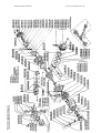
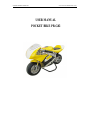
UFREE SPORTS VEHICLE
www.scooter-manufacturer.com
USER MANUAL
POCKET BIKE PB-G02
UFREE SPORTS VEHICLE
www.scooter-manufacturer.com
MINIBIKE-PMI
SERVICE MANUAL FOR USE AND MAINTENANCE AND SPARE PARTS
LIST For your own safety and the safety of others Follow these recommendations
in order to use your MINIBIKE safely and correctly. Read the instructions
CAREFULLY, failure to do so may place yourself and others in extreme and or
ultimate DANGER. If you do not understand the instructions and Data then, you
are not to attempt to operate this Minibike under any circumstances. It may be
used for show purposes only!
CONTENTS
PAGE
INTRODUCTION……………………………………………………………………2
TECHNICAL DATA………………………………………………………………2
UNPACKING AND SETTING UP BEFORE RIDING……………………………...3
SAFETY…………………………………………………………………………..3
BEFORE STARTING……………………………………………………………...3
STARTING THE ENGINE .FIG. 2………………………………………………….4
CARBURETOR.FIG. 3…………………………………………………………….4
RIDING……………………………………………………………………………..4
PERIODIC MAINTENANCE……………………………………………………...5
CHAIN SETTING AND MAINTENANCE………………………………………..5
CENTRIFUGAL CLUTCH REPAIR OR REPLACEMENT………………………...5
BRAKES ADJUSTING .FIG. 4…………………………………………………….6
FRONT BRAKES PADS REPLACEMENT .FIG. 7………………………………..6
REAR BRAKES PADS REPLACEMENT.FIG. 7……………………………………6
REMOVE AND REFIT THE FRONT WHEEL.FIG. 5……………………………..7
REMOVE AND REFIT THE REAR WHEEL . FIG. 5………………………………7
REPLACEMENT OF SPROCKET -FK3.9………………………………………..7
ENGINE……………………………………………………………………………..8
POCKET BIKE PB-G02 .FJG. 5…………………………………………………9, 10
PARTS LIST……………………………………………………………………11 12
FRONT AND REAR BRAKES .FIG. 7…………………………………………….13
REPLACEMENT OF TIRE .FIG. 5…………………………………………………14
DISMANTCING AND ASSEMBLY OF AIR FFLTER-FIG.3…………………..14
WHAT TO DO BEFORE A PERIOD OF IDLENESS……………………………14
1
UFREE SPORTS VEHICLE
www.scooter-manufacturer.com
INTRODUCTION
The Minibike -PB-G02 is designed and built for use on a paved closed circuit
track. The track should be clean and without obstacles of any kind. Qualified
adults and younger persons can drive the minibike. Children can drive the
minibike only under the supervision of a responsible adult person. The
minibike is constructed especially for racing competitions on special racing tracks.
The minibike uses a single-cylinder two-stroke, Gasoline combustion engine, and
has an air filter and exhaust silencer. Transfer of power to the rear wheel is through
a drive chain. The overall drive ratio to the rear wheel can be changed by the
replacement of chain sprockets. The front and rear wheel is equipped with disk
brakes. The rear brake is controlled with the left fever and the front brake is
controlled with the right lever on the handlebars.
BASIC TECHNICAL DATA
ENGINE:
MT-A1……………………………………………TWO-STROKE
NUMBER OF CYLINDERS…………………………………….1
SIZE, CAPACITY…………………………………………...47 cc
ENGINE COOLING SYSTEM……………………AIR COOLED
POWER OUTPUT………………………………2.5kW at 8700rpm
CARBURETOR………………………………………DELL’ORTO
FUEL ADMISION……REED VALVE DIRECT TO CRANKCASE
IGNITION…………………………………………...ELECTRONIC
SPARK PLUG………………………………………….NGK B9 ES
STARTING……………………….HAND PULL TYPE, MANUAL
CLUTCH…………………………….CENTRIFUGAL, FRICTION
FRAME: WELDED…………………………HIGH STRESS STEEL TUBES
BRAKES: FRONT WHEEL…………………………………..DISC BRAKES
REAR WHEEL………………………..MECHANICAL BRAKES
WHEELS: FRONT……………………………OF LIGHT ALLOY 6, 5" - 63
REAR……………………………..OF LIGHT ALLOY 6, 5" - 63
TIRE:
FRONT……………………………………….SIZE 90/65 - 6, 5"
REAR…………………………………110/50 - 6,5", 90/65 - 6,5"
FUEL:
PETROL (GASOLINE)……….OCTANE 92 +SYNTHETIC OIL
MIXING RATIO (after break in period)……………………..50:1
TANK CAPACITY………………………………………..1 Litre
SPEED:
WITH THE INSTALLED RATIO:………..up to28mph(45km/h)
UNLOADED WEIGHT:…………………………………………(41.5lbs.) 19 kg
CARRYING CAPACITY:………………………………………..(240lbs) 110 kg
BASIC DIMENSIONS:
LENGTH…………………………………………………950 mm
WIDTH……………………………………………………500mm
HEIGHT…………………………………………………..565 mm
2
UFREE SPORTS VEHICLE
www.scooter-manufacturer.com
UNPACKING AND SETTING UP BEFORE RIDING
The minibike is delivered in a cardboard carton and packed with folded handlebars
and brake levers. After unpacking, set up the handlebars into the position, that suits the
best for driving. The maximum pulled brake lever position should not touch on the
handlebar grip. After setting up, tighten the handlebar nuts 1, brake lever bolts 2, and
the throttle assy. Bolts. See, Fig. 1. The level of foot rest's can be regulated by
loosening the bolt M5 (914.003.01) on the handle of the foot rest (139.001.01). The
foot rest can be moved to the front or back position. It is recommended to try and check
the position of handlebars and foot rest's individually. While tightening the bolts and
nuts, do not use an excessive force as to not damage the threads, or distort the tubes and
other parts. Verify the smooth and perfect function of the Bowden cables to throttle and
both brakes. Fill the fuel tank with fuel. (Gas-oil mix) Failure to use the proper oil mix
ratio will result in Engine damage for which you will be responsible.
Operating controls:
Fig. 1
1. Handlebar nut
2. Brake lever bolts
3. Throttle Assy. bolts
4. Stop switch
5. Front brake lever
6. Rear brake lever
Range of adjusting handlebars
function position
SAFETY
The minibike is unsuitable for public road use. It does not comply with valid Safety
Standards. Unsafe and careless use of a minibike can result in serious injuries. The
driver can minimize the potential risks by wearing the Safety Equipment The driver
must wear safety helmet, goggles, gloves, elbow pads, kneepads, and firm footwear.
The minibike cannot be used on wet, icy or oily surfaces. Avoid uneven surfaces and
obstacles. Drive with two hands on the handlebars.
BEFORE STARTING
It is strongly recommended to follow all the instructions about the break-in period to
promote engine reliability and long life. Break-in period of the minibike is complete
after the consumption of five full fuel tanks. It Is important to use petrol 91 or 92 Octane
fuel with synthetic oil in the ratio 25:1 and after break-in period a ratio of 50:1. Mix the
gas and oil completely before putting it into the fuel tank. During the break-in period
do not run the engine at maximum RPM and do not allow the engine to overheat
Check the tire inflation - 200 kPa (2 bars) or (28 to 30psi) to be commensurate with the
driver's weight The Tyre pressure should never exceed 2,5 bars, (38psi) in either the
front or rear wheel.
3
UFREE SPORTS VEHICLE
www.scooter-manufacturer.com
STARTING THE ENGINE
To be done only on the starting stand - Fig. 2. After opening the tank filling hole, fill
the lank with fuel and close it by screwing-in cap. Open the petrol supply cock by
turning the small lever into position "ON", Fig. 3. Set the choke lever into position
"C',Fig. 3. Without turning the accelerating handle, pull gently twice the starting
wire and by next quick pull start the engine. It is not allowed to pull the starting wire
up to full winding off. After a short engine run, put the choke lever back to position
"A" and let the engine run about 1 min. Let the Minibike on the larking stand and, if
need be, adjust the no-load speed to such a rate lest coupling should take along the
no-load speed to such a rate lest coupling should take along the rear wheel. For
adjustment use the adjustment screw N° 4 on the carburetor, Fig. 3.
Fig. 2
Fig. 3
CARBURETOR
OFF
1. Suction chamber
2. Sleeve screw
3. Carburetor body
4. Adjusting screw of no-load run
5. Float chamber
6. Fuel cock
RIDE
After mounting the Minibike and slow turning the acceleration handle, you are
starting your ride. Before braking, turn back the acceleration handle and depress
slightly the front brake lever and then the rear brake lever. Beware of the wheels
not to get them in skid.
The Minibike engine will be switched off by pushing the red push-button of the stop
switch on handlerods. After the first half-hour ride it is necessary to check the
tightening of screws and nuts, especially of the engine. Check also the brake setting.
4
UFREE SPORTS VEHICLE
www.scooter-manufacturer.com
PERIODIC MAINTENANCE
Periodic maintenance is the best way to help the machine perform well, give
longevity and provide safety and low cost operation. In addition, you will be
spared from many-worries from self caused problems, resulting from poor
maintinence or no maintinence. A - Before every ride:
1. Check the Cables and efficiency of brakes.
2. Check the lubrication and chain tension settings. The chain free play should
be (5 mm) (.200in) After every ride clean the minibike carefully and keep it
clean. Do not use aggressive cleaning detergents.
3. After 1-hour of use, wash the air filter In air drying spirits and lubricate it
with special oil for air filters.
4. After 1- hour of use, check the state of the clutch pads. Review the clutch
adjustment.
B. After every 5 hours of riding:
5. Check the tightness of all bolts and nuts.
Tighten carefully to prevent
damage to other parts.
6. Wash the air filter in gas and lubricate it with special oil for an air filters to
better catch the dust.
7. Clean carefully the carburetor float chamber.
8. Check the brake pads, the thickness of brake lining cannot be less than 1
mm (.039 in). Review the basic brake adjustment
9. Check the state of the clutch pads. - the thickness cannot be less than 1
mm (.039in). Review the clutch adjustment.
C. Every time after 10 hours of riding;
10. Check the state of the clutch pads - the thickness cannot be less than 1 mm
(.039in).
CHAIN SETTING AND MAINTENANCE
To set the chain tension, loosen the Nut (920.011.01) of the axel thru the rear
wheel and the nut (914.021.01) of the rear Caliper anchor plate. The required
chain tension (chain free play ) is (5 mm) (.200in) and is performed by equal
movement of the Axel adjustor plate (920.009.01) on the both sides of the rear
wheel. When the adjustment is correct, tighten the Axel nuts and the Caliper
holding nut Tighten the adjustor plate nuts both sides an extra nip, just to set them
firmly. It is important to lubricate the chain regularly, to avoid excess wear and
prolong effective lifetime. The lubrication is important after every ride on a wet
surface. It is recommended to lubricate the minibike with special chain spray. If
chain replacement is necessary, check both chain Sprockets and if there is a need
to change them do it together with the chain.
CENTRIFUGAL CLUTCH PARTS REPLACEMENT
Remove the chain guard by loosing two bolts M6 (916.020.01), Fig. 5. Loosen
the chain and remove it from the sprocket. Next, loosen three bolts holding the
aluminum clutch housing. Remove it together with steel clutch basket, and
dismantle it Loosen the bolt from the carrier and remove the clutch from the
engine. Loosen and remove the adjustable bolts and springs. Then dismantle the
safety rings from pins. When all this is done, replace with new clutch slipper
shoes and springs (if required) at this time. During the reassembly process follow
these steps: 1. put the plate with the springs on the slipper shoes. 2. Put the plate
against the carrier and mount it on the fixed pins. Fit it with the safety rings and
install the adjustable bolts.
5
UFREE SPORTS VEHICLE
www.scooter-manufacturer.com
ADJUSTING THE BRAKES
Fig. 4
Fine brake adjusting: Fine
brake adjustment can be
carried out on both ends of
brake bowden wire by means
of the screw 1 and nut 2.
Basic brake adjusting:
It is carried out in such a way,
at first, the nut 2 will be
loosened and the screw 1 of
fine tuning screwed-in.
Loosen the locking nut 3 and
tighten the adjusting screw 4
so that the wheel can be free
turned. Tighten the locking
nut 3.
Don't release the wire catcher 5!
FRONT BRAKE PADS REPLACEMENT: FIG.7
At first, loosen the nut 920.006.01 of fine front brake adjustment. Screw-in fully the
screw. Unscrew maximum the adjusting screw and lock it by fine tightening the nut
920.001.01. Dismantle the front wheel. Unscrew the nuts 920.008.01 on the front
brake and remove the screws 911.001.01. Unscrew two screws 914.009.01 from the
side of control lever on brake body and separate both bodies 512.011.00 each other.
Remove the old brake pads from both parts. Slide the brake plate, fitted with pin, into
the part with operating mechanism. Force on carefully the brake plate into the opposite
piece. Before reassembly clean the whole brake. Assembly follows in reverse sequence.
REAR BRAKE PADS REPLACEMENT: FIG.7
Before replacing the rear brake lining it is necessary to loosen the nut 920.006.01 of
fine adjustment of rear brake. Screw-in fully the screw of fine adjustment. Loosen the
nut 920.001.01 of basic adjustment. Unscrew maximum the adjustment screw
112.030.00 and lock it by fine tightening the nut 920.001.01. Don't release the wire
catcher 512.016.00 and dismantle the rear wheel. Shift the whole brake out of the
guide pins. Unscrew both screws 912.003.01 from the control lever side. Separate both
bodies 112.003.00 each other and shift the worn-out brake plates out of guide pins
clean carefully the brake and put the new brake plates on the guide pins so that they face
by lining towards themselves. The assembly follows in a reverse way. After mounting
the rear wheel carry out the chain adjustment and basic brake adjustment.
6
UFREE SPORTS VEHICLE
www.scooter-manufacturer.com
REMOVE AND REPLACE THE FRONT WHEEL - FIG. 5
Before dismantling the front wheel it is necessary to remove the front brake
pads from the front brake, so it is possible to move the brake caliper from the
wheel and be able to draw out the wheel and tire. Remove the front axel nut.
M10 (920.011.01) . Draw out the axel from the fork and wheel. Remove the
wheel by an easy pull downwards from the forks. Caution, while removing the
wheel the left side spacer washer will fall out! During the assembly process put
the spacer washer between the brake rotor and brake caliper mount plate and the
right side distance spacer between the wheel and right fork (315.011.00).
Return the brake pads with the spring and tighten up the axel nut Perform the
basic brake adjusting. Double check your work. This is important!'
REMOVE AND REPLACE THE REAR WHEEL - FIG. 5
Remove the rear wheel axel nut. Loosen the nut on the real caliper anchor plate.
Remove the two wheel adjustor plate nuts. (M6) Move the wheel forward and
remove the chain. Safely (hold) keep the rear wheel front .ailing out while pulling
out the axel. Caution, note the location of both spacer tubes and one spacer
washer (between caliper mount plate and rotor) while removing wheel. When
refitting the wheel, make sure to slide the brake rotor into the caliper between the
pads. Hold the wheel in place and fit the wheel spacers in proper order, Insert the
spacer washer between the caliper plate and the brake rotor and on the both sides
place the axel spacers at the appropriate time during assembly. Adjust chain
tension and tighten axel nut Tighten the caliper holder plate nut and set and
tighten both chain adjustor plate M6 nuts. At this time check the brake operation.
Recheck all your work. This is important!
PINION EXCHANGE: FIG.6
Fig. 6
First dismantle the front lining and
chain guard. Loosen the nut of rear
wheel axle and the nut of chain
tightener, remove chain, insert
carefully a larger screwdriver or
steel rod into the hole of clutch
drum, Fig. 6, to avoid a turning
over the clutch drum releasing the
pinion. Using the socket wrench
size 14 mm, release the new pinion
to carried out by reverse way.
7
UFREE SPORTS VEHICLE
www.scooter-manufacturer.com
8
UFREES PORTS VEHICLE
www.scooter-manufacturer.com
9,10
UFREE SPORTS VEHICLE
C40.00.000
E40.00.000
MINIBIKE
E40.001.01
E40.002.00
E40.004 00
E40.004.01
E40.004.02
E40.004 03
E40.005.00
E40.006.00
E40.006.01
E40.006.02
E40.006.03
E40.008.00
E40.011.00
E40.015.00
E40.017.00
E40.019.00
E40.020.00
E40.021.00
E40.022.00
E40.024.00
E40.023.00
E40.031.00
E40.032.00
E40.053.00
E40.055.00
E40.056.00
E40.057.00
E40.059.00
E40.060.00
E40.063.00
E40.065.00
E40.067.00
E40.068.00
E40.069.00
E40.069.01
E40.069.02
E40.069.03
E40.070.00
E40.072.00
E40.073.00
E40.074.00
E40.075.00
E40.076.00
E400.077.00
E40.078.00
E40.080.52
E40.097.00
E40.098.00
E40.099.00
E40.100.00
E40.101.00
E40.102.00
ENGINE
ENGINE COMPLETE
ENGINE PROPER
CARBURETOR SHA 1412L
PISTON COMPLETE • A
PISTON COMPLETE•B
PISTON COMPLETE • C
PISTON COMPLETE • D
PISTON RING
PISTON •A
PISTON• B
PISTON•C
PISTON• D
WRIST • PIN
CRANK BALANCED
CLUTCH DISC
CLUTCH LEVER - 2 PCS
CLUTCH SCREW COMPLETE
CLUTCH SCREW SCREW
CLUTCH SPRING • SERIE 1.25 - 2 PCS
CLUTCH SPRING • RACING 1.4-2 PCS
CLUTCH DRUM
CLUTCH CASE
CLUTCH CASE COMPLETE
CLUTCH COMPLETE
ENGINE COVERING
ENGINE SEALING SET
'
FLANGE
DIAPHRAGM SEALING - 2 PCS
DIAPHRAGM
DIAPHRAGM WASHER
SEALING ENGINE BLOCK
ENGINE BLOCK
DIAPHRAGM COMPLETE
SEALING
CYLINDER •A
CYLINDER•B
CYLINDER • C
CYLINDER• D
CYLINDER + PISTON COMPLETE
EXHAUST SEALING
PLASTIC CONNECT, FUEL COCK
FUEL COCK
EXHAUST COMPLETE
EXHAUST SILENCER COMPLETE
SILENCER MASS
RING
JET 52
FLOAT CHAMBER SEALING
CARBURETOR SEALING 1
ADJUSTING SCREW
TROTTLE VALVE
CARBURETOR FILTER
NEEDLE VALVE
E40.103.00
E40.104.00
E40.105.00
E40.185.00
E40.002.00
E40.003.00
E40.004.00
E40.005.00
E40.006.00
E40.007.00
FLOAT
CARBURETOR SEALING 2
TROTTLE VALVE SEALING
JET SET
STARTER COMPLETE
STARTER ROPE
HOLDER
HOLDER
GUIDE BUCH
STARTER CASE
www.scooter-manufacturer.com
E40.008.00
E40.009.00
E40.011.00
E40.015.0
E40.017.00
E40.020.00
E40.108.00
STARTER SPRING
RATCHET WHEEL
WASHER 4.5×16×1.5
WASHER 8.1×16×1
WASHER 6.1×16 × 1.5
PINION
CONNECTING ROD BEARING
C40.00.000
FRAME
FRAME, VARNISHED
BRAKES
C40.10 907
BRAKE COMPLETE
107.003.00
BRAKE CASE - 1 PAIR
107.004.00
LIFTER, RIGHT
107.005.00
REAR PAD-2 PCS
C40.10.004
BRAKE REACTION LIFTER
107.009.00
SPRING, LEFT
107.015.00
BRAKE HOLDER COMPLETE
C40.10.016.
BRAKE HOLDER
107.017.00
LEADING PINS
107.017.01
LEADING PINS
107.018.00
BOWDEN CABLE • REAR BRAKE
BOWDEN CABLE • FRONT BRAKE
107.022 00
FRONT BRAKE DISC 3.0 × 119
C40.03.003
REAR BRAKE DISC 3.0 × 119
C40.10.002
ADJUSTING SCREW
107.112.030.00
BRAKE COMPLETE
C40.02.907
HANDLE BAR LEVER. RIGHT
C40.01.910 512.004
HANDLE BAR LEVER. LEFT
C40.01.911 512.005
027.008.00
UFTER.LEFT
027.011 00
BRAKE CASE • 1 PAIR
DISC BRAKE PADS • 2 PCS
027.012.00
LIFTER LEVER
027.013.00
SPRING RIGHT
027.014.00
TERM. CLAMP BOWDEN
027.016.50
FRONT BRAKE HOLDER
027.017.00
WASHER
027.019.00
ADJUSTING SCREW
027.024.00
BOWDEN HOLDER
027.025.00
WHEELS
C40.10.604
SPACER
L=14.5
C40.10.906
CHAIN STRETCHER COMPLETE
C40.03.901
TIRE 90/65-6.5×8- SLICK
C40.10.901
TIRE 110/50-6.5×8- SLICK
C40.10.608
WHEEL AXLE M10×220
C40.10.902
VALVE 90*-TU8EIESS
C40.03.604
WHEEL AXLE M10 × 165
C40.03.001
RIMVHUBASSY 6.5×-63 -90
C40.10.001
RIMVHUBASSY 6.5". 63-130
C40.03.900
WHEEL COMPLETE W/O TIRE 6.5" 63-90
C40.10.900
WHEEL COMPLETE W/O TIRE 6.5' - 63 -130
C40.03.603
AXLE SPACER L=7
C40.02.602
AXLE SPACER L=84.5
C40.03.602
AXLE SPACER L=76.5
C40.10.602
AXLE SPACER L=117.5
C40.00.007
C40.00.001
C40.00.801
C40.00.003
C40.00.002
C40.00.803
C40.00.802
C40.00.805
C40.13.602
C40.01.004
C40.02.003
C40.02.001
C40.01.901
C40 01.906
C40.01.903
C40.01.907
C40.02.802
C40.02.801
C40.02.001
C40.02.002
STEERING
BOWDEN OUST GUARD
CAP
NUT
HANO-GRIPS (PAIR)
CAS CABLE SLEEVE ASSY
THROTTLE TWIST GRIP
HANDLEBAR COMPLETE
FORK WITH DRAKE HOLDER
RIGHT FORK
FORKS HOLDER ABOVE- COMPLETE (w 130)
FORKS HOLDER BELOW-COMPLETE (w 130)|
C40.10.003
C40.00.806
TRANSMISSION
SPROCKET 68TEETH
CHAJM140 LINKS
ELECTRIC COMPONENTS
E40.003.00
SPARKPLUG
E40.002.00
ROTOR COMPLETE
E40.001.00
IGNITION COMPLETE
E40.005.00
SPARK PLUG CAP
C40.01.905
KILL SWITCH
OTHER PARTS
C40.00.608
SPACER L=258
C40.00.007
CHAW ROLLER
C40.06.003
C40.06.901
C40.00.004
C40.00.804
C40.00.607
C40.05.001
C40.16.002
C40.06.003
C40.13.602
C40.00.901
C40.00.902
C40.00.006
C40.02.601
C40.107
C40.03.601
C40.01.606
GAS TANK WITH CAP
GAS TANK W/O CAP
GAS TANK CAP
RUBBER FRAME PAD
STAND
WASHER 6.4 × 18 ×1
RUBBER SEAT
FUEL HOSE
HOSE CLAMP 11/7
WASHER
ADJUSTABLE FOOT REST .RIGHT
ADJUSTABLE FOOT REST -LEFT
FOOT PEGS PLASTIC-PAIR
C40.10.002
C40.00.015
E40.005.01
C40.00.611
C40.13.603
E40.009.01
E40.010.01
E40.01101
E40.001.01
E40.004.01
E40.005.01
C40.00.604
E40.916.065.02
S C R E W M 5 ×1 6
SCREW M 5 × 20
SCREW M 5× 30
SCREW M 6 × 16
SCREW M 5 ×20
SCREW M 6 × 22
SCREW M 6 × 25
SCREW M 6 ×30
SCREW M4 × 8
SCREW M4 ×10
SCREW M 6 ×16
SCREW M 6 ×40
SCREW M 5 ×25
107.001.01
C40.13.601
107.008.01
C40.10.001
C40.01.601
C40.03.105
E40 012.01
NUT M5
NUT M 6
NUT M 5 SELF-LOCKING
NUT M 6 SELF-LOCKING
NUT M 8 SELF-LOCKING
NUT M 10 SELF-LOCKING
NUT M 8 LEFT
40.003.01
40.010.00
40.011.00
WASHER 10.5
WASHER 8.4
WASHER 8.1
107.001.00
107.006.00
RIVET 4 ×8
ROLLER 6 ×6
40.003.00
40.005.00
43.007.00
40.006.00
40.010.00
WOODRUFF KEY 3e7 × 3.7
WOODRUFF KEY 2e7× 3.7
LOCK 15
LOCK 35
PISTON PIN LOCK RING
960.003.00
BEARING 6000 2R
960.004.00
BEARING 6200 2R
40.006.00
BEARING 6202 C3
JOINING ELEMENTS
40.007.00
BEARING 6202 2ZR
SCREW M 10 ×140
SCREWM5×25
SCREW M 5 ×16
SCREW M 8 × 35
40.001.00
PACKUNG RING 12×22 × 7
40.002.00
PACKUNG RING 15×26 × 7
BODY
CHAIN GUARD
FRONT FENDER NOW VARNISHED
FRONT FENDEA VARNISHED
GLASS BODY WT COMPLETE NON VAANISHEO
GLASS BOOY KIT COMPLETE VARNISHED
FAIRING NON VARNISHED
SEAT-TA4 ASSEMBLY NON VARNISHED
FAWING VARNISHED
SEAT-TALL ASSEMBLY VARNISHED
WINDSHIELD +RIVETS
RUBBER WASHER 5.5 ×23.5× 5
11,12
UFREE SPORTS VEHICLE
www.scooter-manufacturer.com
C40.02.907 - FRONT BRAKE COMPLETE
C40.10.907 -REAR DRAKE COMPLETE
Fig.7
13
UFREE SPORTS VEHICLE
www.scooter-manufacturer.com
REPLACEMENT OF TIRE - FIG.5
Remove the wheel from the minibike. For the front wheel unbolt the brake disk
and for the rear wheel, the brake disk and sprocket. Deflate the tire by
removing the valve stem. Place the wheel on a hard surface and press the tire
bead from the wheel rim in to the middle relief at centre of rim. Tire is ready to
be removed from the rim at this time and is done in the conventional manner.
After fitting new Tire and Tube (if necessary) to the rim, you can inflate 28 to 30
psi. Take care to check that the tire bead is fully seated in the rim bead edge
You can new refit the wheel to the bike in reverse order to removing it Use
Caution and recheck your work always.
DISMANTLING AND MOUNTING OF AIR FILTER - FIG. 3
Dismantling the air filter unscrew 2 and so ease the holder and put down the
suction chamber 1. On this way you gain access to the filter that you can take off
by means of screw driver. After cleaning and lubricating it with engine oil
proceed the assembly on a reverse sequence.
WHAT TO DO BEFORE A PERIOD OF IDLENESS:
Should the minibike not be used for a more or less longer period, take care and
make measure as follows:
• Remove petrol from the fuel tank
• Store the minibike on a smooth and dry place
• Protect it from dust
• Remove the spark plug, clean it, put some drops off fuel with oil into the
cylinder, pull 2-3 times the starter rope to distribute oil drops and then screw-in
the spark plug.
Thank you for your selection of our product. Our wish is that the Minibike may
serve you a long time and trouble-free, contribute to your satisfaction and bring
you a pleasure.
14