1
TABLE
OF CONTENTS
IMPORTANT SAFETY PRECAUTIONS ..........................................................
BEFOREYOU BEGIN ......................................................................
./
2
ASSEMBLY .............................................................................
ADJUSTING THE CROSS TRAINER e ...........................................................
TROUBLE-SHOOTING AND MAINTENANCE ....................................................
3
8
9
OPERATING THE STEPPERCONSOLE .........................................................
OPERATING THE PERSONAL TRAINER COMPUTER ...............................................
Calories ............................................................................
11
12
13
EXERCISEGUIDE ........................................................................
PART UST ...................................................................
EXPLODED DRAWING ...................................................................
..........
ORDERING REPLACEMENTPARTS ....................................................
UMITED WARRANTY ..............................................................
IMPORTANT
SAFETY
16
25
26
Back Cover
Back Cover
PRECAUTIONS
WARNING: To reduce the risk of serious injury, read the following important safety precautions before using the
CROSS TRAINER e. Before beginning any exercise program, consultyour physician. This is especially irnportont for
parsons over the age of 35 or parsons with pre-existing health problems. SEARSassumes no responsibility for personal injury or properly damage sustained by or through the use of this product.
I.
Read this owner's manual and the accompanying FITNESSJOURNAL carefully before using the CROSSTRAINERe.
Use the CROSS TRAINER e only as described.
2.
Inspect and tighten all parts each time you use the CROSSTRAINERe. Replace any worn par_ immediately.
3.
Do not use the transformer if it is damaged. Keep the power cord away from walkways
4.
Keep your hands away from moving parts. Always wear athletic shoes for foot protection.
5.
Keep small children away from the CROSS TRAINERe at all times.
6.
To prevent damage to the weight system, do not put any pressure on the leg developer, arms or cables while the
weight sefflng is changing. If the kit bar or rower bar is attached to the high pulley station, rest it in the rack near the
and heated surfaces.
high pulley station. (See OPERATINGTHE PERSONALTRAINERCOMPUTERon page 12 of this owner's manual).
•
7. Always stand on the foot plate when _rformlng
8.
• 9.
:
any exercise that could cause the CROSS TRAINER e to tip.
Make sure that the cables remain in the grooves in the pulleys as you use the CROSS T_dNER e.
The resistancecylinders become very hot during use. Allow the resistancecylinders to cool before buching
them. Cover the floor beneath the stepper for protection; a small amount of oil leakage is normal for hydraulic
cyfinders. When uslng the stepper, keep your fee.
t on the pedals atall time s. If you lift your feet off the pedals;
the i_c/oIs'm_; b_ome's_!0arated from the resistancec'y_inde_s,resulting in injury.
10. If you feel pain or di=iness at any time while exercising, stop imr.Jedlatelyand begin cooling down. Find out
'what is wrong before continuing.
•
-'r
I
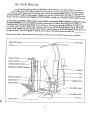
RE YOU
BEGIN
,hans for purchasing the revabtioeary
PROFORM* CROSS TP,_NER e. The CROSS TP-_NER e comb;nes ¢
.arian weight system with a full-slze stepper to let you enjoy true cross tra_ning workou_ in the convenience oF
• -,ur own home. And to help you get the mast from every workout, the CROSS TRAINER e fea_res the advanced PERSONAL TP,AINER TM weight training computer. Whether your goal is improvedcardiovascular fitness, a shapely, toned
body or dramatic muscle slze and strength,the CROSS TRAINER • w_]) help you to achieve the specificresu|_ you want.
For your safely and benefit, read this owner's manual and the accompanying FITNESSJOURNAL carefully before using
the CROSS TRAINER e. If you have additional questions,please call our CustomerSe_ce Depar_ent toll-free at
1-800-999-3756,
Monday through Friday, 6 a.m. until 6 p.m. Mountain Time (excluding holidays). To help us assist
you qulckty, please note the model number and serial number oEyour CROSS TRAINER e before calling. The model
number is 831.159340. The serial number can be found on a decal affached ta the CROSS TRAINER e. The location of
the decal is shown in the drawing below. Write the serial number in the following space for reference:
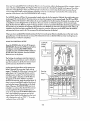
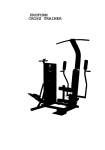
Before reading Further, please review the drawing below and fomiJlarize yourself with the parts that are labeled.
Cable Cllp
High Pulley Station
Lot Bar
Stepper Console
Stepper Handle
CUSTOM SMART CARD
t
Backrest
Seat
Leg Developer
t
Selector Knob
SerialNo.
Decal
Low PulleyStation
Foot Plate
WelghtCable
2
ASSEMBLY
Assembly requires two persons. To assemble the CROSS TRAINER e, use the included videocassette or follow the
instructions below. Due to the weight oFthe CROSS TRAINER e, it should be assembled in the location where it will be
used. Place all ports in o cleared area and remove the packing materials. Do not dispose of the packing materials until
assembly is completed. Make sure to lower the resistancecylinders and pedals before beginning assembly; if the
resistance cylinders fall, they may damage the side shields. Read each assemblystepand examine each drawing
carefully. Make sure that all ports are oriented as shown in the drawings.
Thefollowing tools (not included)are required for ass_'nbly:two 8' Adjustable Wrenches_
RubberMallet _.
1.
and a
Theincludedlubricant and a smallamount of soapywater are also required.
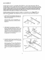
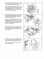
Set the Front Base (7) and the Rear Base (8) on the
floor as shown. Turn the Rear Base so the indented
holes are toward the Floor.
Insert seven3/8" x 2 1/2" Carriage Bolts (1) up
through the indicated holes in the Front and Rear
Bases (7, 8).
7
2.
With the help of o second person, set the Tower
Frame (10} near the indicated ends of the Front and
Rear Bases (7, 8). The Tower Frame mustbe turned
2
so the Pedals (75, 76) are on the someside as the
extension on the Front Base. Raise the Tower Frame
and lower it onto the two indicated 3/8" x 2 1/2"
Carriage Bolts (1) in the Rear Bose.
,
Raise the front of the Tower Frame (I O) and lower it
onto the two indicated 3/8"
x 2 1/2" Carriage Bolts
(1) in the Front Base {7).
3
.
10 j.
Adjust the position o_ the Tower Frame (10) so the
four indlcoted 3/8 _'x 2 1/2" Carriage Bolts (1) are
centered in the slotted holes in the Tower Frame.
Thread a 3/8"
2
Nut (2) with el-3/8" Lockwasher (3)
onto each Carriage Bolt. Do not tighten the Nuts
yet.
3
2
s
.
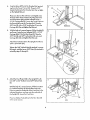
._ilc_ethe Brace (29) onto the threaded boff protruding from the Tower Frame (10). Thread a 3/8"
4
Nylock Nut (6) onto the threaded bolt. Do not tighten the Nytock Nut yet.
29 6\
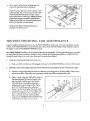
Place your Foot on lhe extension and slighl_yraise
the front of the Tower Frame (10). Align the lower
• end oFthe Brace (29) with the indicated 3/8" x
2 1/2" Carriage Bolt (1). Lower the Tower Frame so
the Brace slidesonto the Corrlage Bolt. Thread a
3/8" Nut (2) with a 3/8" Lack'washer(3) onto the
Carriage Bolt. Do not t_ghtenthe Nut yet.
5.
With the help of a second person, lift the Upright (9)
and lower it onto the two indicaled 3/8" x 2 1/2"
Carriage Bolts(1) in the Rear Bose (8). Thread a
3/8" Nut (2} and 3/8" Lockwasher (3) onto each
Carriage Bolt. Do not tighten the Nuts yet.
2
Attach the Front Bose (7) to the Upright (91 with two
3/8" x 3/4" Bolts (31).
Tighten the 3/8"
Nylock Nut (6) attached in assem-
bly step 4, and the seven 3/8"
assembly steps 3 through 5.
Nuts (2) attached _n
-9
"\
;\
\.
,
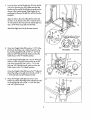
Attach the Foot Plate (102) to the Upright (9) with
two 3/8" x 3/4" Bolts (31) and 3/8" Nylock Nuts
(6).
With the help of"a second person, lib the Front Base
(7).Peelthe backing off three Rubber Pads (48).
Presstwo onto the underside oFthe Front Base in the
indicated locations, and one onto the underside oF
the Upright (9). Lower the Front Base.
Press two Rubber Pods (4B) onto the Rear Base (8)
in ,'hesame manner.
4
.
Insert the lower end oF _ne Le[t Arm (15) into the refi'
7
side of the Moment Arm (74). Make sure that the
bracket on the end of the Left Arm is positioned as
shown in the inset drawing. If the bracket is not
positioned as shown, the Left Arm will not function
properly.
Align the hole in the end of the Le[t Arm (15) with
the holes in the Moment Arm (74_. Insert the 3/4" x
4" Axle (54) into the Moment Arm and the Left Arm.
Tap a 3/4"
Plastic Cap (57) onto the Axle.
15
Attach the Right Arm (16) in the same manner.
/
/
/
/
/
.
Cibrrect position of Arms
again._t Moment Arm
"
74
Wrap the Weight Cable (52) under a 3 1/2" Pulley
(5). Attach the Pulley and a Cable Trap (67) to the
INCORRECT
back of the Upright (9] with a 3/8" x 1 3/4" Bolt
(40) and 3/8" Nylock Nut (6). Make sure that the
Cable Trap is in the "7 o'clock" position.
Lay the Weight Cable (52) over a 3 1/2" Pulley (5}.
Attach a Cable Trap (67) and the Pulley to the [eft
side oF the Upright (9] with a 3/8" x 1 3/4" Bolt
(40) and 3/8" Nylock Nut (6). Make sure that the
Cable Trap is in the "12 o'cloc_ position.
Wrap the Weight Cobb (52) around a 2" Pulley (4).
Attach the Pulley to the Left ,_'m (15) with a 3/8" x
1 3/4" Bolt (40) and 3/8"
.
4O
Nylock Nut (6}.
Wrap the Weight Cable (52) around a 2 3/4"
Pulley (13). Attach the Pulley to the indico_ed bracket
on the Upright (9) with a 3/8" x 1 3/4"
and 3/8" Nylock Nut (6).
9
Bolt (40)
S
67
5
67
5
CORRECT
10. Wrap the Weight Cable (52) around a 2" Pulley (4).
10
Attach the Pu]Yeyto the Right Arm (16) with a 3/8" x
1 3/4"
BOlt(40) and 3/8"
4O
N/lock Nut (6).
Lay the Weight Cable (52) over a 3 1/2" Pulley (5).
Attach a Cable Trap (67) and the Pulley to the side
of the Upright (9) with a 3/8" x 1 3/4" Bolt (40)
and 3/8" N/lock Nut (6}. ' _ake sure that the Cobb
Trap is in the "12 o'clock" position.
1 I. Wrap the Weight Cable (52) under a 2 3/4' Pulley
(13). Attach the Pulley to the bracket on the side of
the Moment Arm (74) with a 3/8" x 1 3/4" Bolt
(40) and 3/8"
11
Nylock Nut (6).
Attach the end oFthe Weight Cable (52) to the right
side oF the Leg Developer (23) with a 3/8" x 2" Bolt
(45) and 3/8" Nylock Nut (6). Do not overfighten
the Nylock Nut, the Cable must be able to swivel
freely or it will be damaged.
12. Insert the threaded bolt on the end oFthe Weight
Cable (52) into the Adjustment Bracket (53). Thread
the 5/16" Nut (82) exactly two complete turns onto
the threaded boil
12
13. Wet the upper ends of the Left and Right Arms (15,
16) and the insides of the two Large Pads (17) with
soapy water. Slide the Large Pods onto the Arms.
Attach the Backrest(19) to the Upright (9) w_ two
1/4" x 2 1/2" Bolts(46).
6
14. Attach the Seat (28) to the Upright (9} with the two
1/4" x 3/4" Bolts (20) and a 1/4" x 2 1/2" Bolt
(46).
15. Center one Pad Tube (22) in the Upright (9), and the
other Pad Tube in the Leg Developer (23). Slide the
four Small Pods (17) onto the ends of the Pad Tubes.
16. Rest the Left and Right Pedals (75, 76) on the hooks
at the lower ends of the Resistance Cylinders (84).
Make sure that the hooks are fully inserted into the
same slots under both Pedals.
Plug the TransFormer (39) into the jack located near
the bottom of the Right Side Shield (12).
17. Make sure that oil ports are properly tightened. The use of oil remaining PoX will be explained in ADJUSTING
THE CROSS TRAINER e, beginning on page 8 oFthis owner's manual.
18. Before using the CROSS TRAINER e, test the cables and the pulleys. Make sure that the cables are in the grooves
in the pulleys. If the cables do not move smoothly over the pulleys, locate and correct the problem before using
the CROSS TRAINER e. If the'€':ables are not properly routed, they will be damaged when used.
7
ADJUSTING
THE
CROSS
TRAINER
e
The CROSS TRAINER e is designed to be changed from stc'bn to station quickly and easily. The instruc'ffons b_Jow
describe how each part of the CROSS TRAINER e can be adiusted. Please read these instructions carefully before using
the CROSS TRAINER e. ReFerto pages 17 through 24 o_ this owner's manual to see how the CROSS I"R,_NER e should
be set up for each individual exercise.
IMPORTANT: For effectlve exercise, the CROSS TRAINERe must be set up correctly for each exercise. Wllen attaching the lat bar, rower bar or strap, attach them directly to the CROSS TRAINER e or use the chain to atfach them;
make sure that the lat bar° rawer bar or strap _sin the correct starting position for each exercise. If there is any
slack in the cable or chain as you perform an exercise, the effectiveness of the exercise will be reduced.
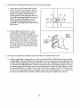
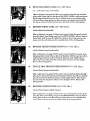
1.
CHANGING
THE STEPPING RESISTANCE
To change the resistance oF the Pedals (75, 76}, first
lift the Pedals off the hooks at the lower ends of the
Resistance Cylinders (84). Move the hooks to different slotsunder the Pedals. Make sure that the hooks
are fully inserted into the same slots under bath
Pedals. The farther the hooks are from the Tower
Frame (10), the greater the resistance will be.
WARNING: The Resistance Cylinders become very
hot during use. Allow the Resistance Cylinders to
cool before touching them.
2o
CHANGING THE ARMS TO THE BUTrERFLY
MODE AND PRESSMODE
The Arms (15, 16) can be changed to either the buttartly mode or the press mode. To perform the BUTTERFLYexercise, change the Arms to the butterfly
mode by lurning the Selector Knob (55) so the
Selector Plate (66) is vertical. To perform the BENCH
PRESSexercise, change the Arms to the press mode
by fuming the Selector Knob so the Selector Plate is
horizontal.
3°
A'I-lrACHING THE LAT BAR, ROWER BAR OR
STRAI_ TO THE HIGH PULLEY STATION
Attach the Lot Bar (36) to the Main Cable (51) with a
Cable Clip (33). For some exercises, the Chain (38)
should be attached between the Lot Bar and the
Main Cable with two Cable Cllps. Adjust the length
oF the Chain between the La'tBar and the Main
Ce%le so the Lat Bar is in the correct sta_ng posltion For the exercise to be performed.
The Rower Bar (34) or the Strap (35) con be
attached in the same manner.
8
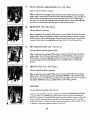
_°
AI"T._,CHING THE I-AT BAR, ROWER BAR OR
STRAP TO THE LOW PULLEY STATION
Attach the Lot Bar {36} to the Main Cab}e (51) with a
Cable Clip (33). For some exercises, the Chain (38}
should be attached betweenthe LOtBar and the
38
34
Maln Cable wlth two Cable Clips. Adjust the length
of the Chain between the Lot Bar and the Main
Cable so the Lot Bar is in the correct starting position for the exercise to be performed.
33
The Rawer Bar (34} or the Strop (35) can be
altached in the same manner.
TROUBLE-SHOOTING
AND
MAINTENANCE
Inspect and tighten all parts each time you use the CROSS TRAINER e. Replace any worn ports immediately. Outside
surfaces of the CROSS TRAINER e can be cleaned using a damp clothand mild detergent. Keep all liquids away Earn
the stepper console and the PERSONAL TRAINERcomputer.
Most CROSSTRAINER e problems can be salved by follow;ng the steps below. F_ndthe applicable symptom and follow
the step(s) listed. If further ossis_nce is needed, coil our Customer Service Department toil-free at 1-800-999-3756,
Monday through Friday, 6. a.m. until 6 p.m. Mountain .time (excludlng holldays).
1.
SYMPTOM: THE POWER DOES NOT TURN ON
a.
2.
Make sure that the transformer is fully plugged into the jack on the CROSS TRAINERe, and into a 120-volt ou_et.
SYMPTOM" THE MAIN CABLE DOES NOT MOVE SMOOTHLY, OR THERE IS SLACK IN THE MAIN CABLE
a.
b,
Inspect the routing of the cables and make sure that they are in the grooves in all of the pulleys. If they are not,
correct the problem. If the cables are not properly routed, they will be damaged when used.
If there is slack in the Main Cable (51}, locate the
Adjustment Bracket (53) near the bottom of the
53
right side shleld. Hold the end of the Weight
Cable (52) Firmly, and s}ide the Adjustment
Bracket farther onto the Weight Cable..tighten
13
\
the 5/16" Nut (821 against the Adjustment
Bracket. Test the Main Cable. IFthe motor stalls
or hesitates, loosen the 5/16"
Nut slightly, ffthe
5/16" Nut is tightened as Faras Passib}e and
there is still slack, the Mo;n Cable should be
replaced. See ORDERING REPLACEMENTPARTS
on the back cover oF th_sowner's manual.
51
9
52
3.
SYMPTOM: THE STEPPERCONSOLE DOES NOT FUNCTION PROPERLY
O.
As you step, move the stepper pedals vertically
at least 8 inches. IFyour stepsore too shallow,
the movement oF the stepper pedals will not be
detected. IFthe stepper console still does not
92
function properly, loosen the Reed Switch Screw
99
\
(92). Hold down the Right Pedal (76). Adjust the
position of the Reed Switch (99) so there is a
76
ff----T
1/8" gap between the Reed Switch and the
\
Magnet (81) on the Right Pedal. righten the Reed
Switch Screw.
b.
81
If the LCD display becomes dim, the 1.5-volt
watch batteries in the Stepper Console (88)
should be replaced, Using a short phillips screwdriver, remove the two screws attaching the back
Back oF
Step_r
Conso(e
"88_
"" ,,
oFthe Stepper Console. Using the screwdriver,
carefully push the two batteries out oFthe battery
1..5-Volt J
clips; be cereful to note which way the batteries
are turned. Insert two new 1.5-volt watch hotter-
Watch _
Ba_'eries
.,
/
/
ies into the battery clips. Reattoch the back of the
Stepper Console.
•
4.
crews
SYMPTOM: THE PERSONAL TRAINER COMPUTER DISPLAYS AN ERROR CODE ("EEE")
a,
While the weight settingischanging, the motor wiU be heard and the SETSand REPSdisplayswill show a rapidly
rotating indlcator. To prevent damage to the weight system,do not put any pressure on the leg developer, arms
or cables while the weight settingis changing. If the lot hor or rower bar is attached to the high pulley station, rest
it in the rock near the high pulley stofion.Walt for the sound oFthe motor to stop before you continue. If the computer sensespressure on the weight systemwhile the weight settingis changing, the WEIGHT display will show
on error code ("FEE"} for two seconds,and the weight se_ng will stop changing. The WEIGHT display will then
show the current weight setting. Make sure that there is no pressure on the leg developer, arms or cables. Press
the increase or decrease button beneath the WEIGHT display to change the weight settingas desired.
10
OPERATING
THE
STEPPER
CONSOLE
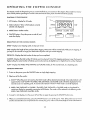
The stepper console is designed to give you instant _:eedbackas you exercise on the stepper. Please read these instructions carefully before operating the console. Note: Remove the clear plastic kom the front of the conso]e.
DIAGRAM OF THE CONSOLE
1. LCD display -Display for all modes.
7;ME
2. Mode indicators--Show which mode _scurrently
seleded and d_spbyed.
3. MODE button--Selects modes.
4. ON/OFF
butto_Turns
D/STANCE
C4LORIE
MODE
the power on and off, and
3 -I
resets the display.
SCAN
ON/OFF
I[
]
4
DESCRIPTION OF THE CONSOLE MODES
SPEED_DispIays your stepping speed, in stepsper minute.
TIME"Displays the length of time you have been stepping. Note: Time will be counted only while you are stepping. If
you stop for ten seconds or longer, the TIME mode will pause until you resume stepping.
DISTANCE--Displays
the total number of steps you have completed.
CALORIE'_Displays the total number of Calories you have burned, Note: If the stepping resistance is near the lowest or
highest setting, the adual number of Calories you have burned may be sllghl_ylower or higher than the number displayed,
SCAN--Displays
the SPEED, TIME, DISTANCE and CALORIEmodes, for five secondseach, in a repeating cycle.
CONSOLE OPERATION
1. To turn on the power, press the ON/OFF button or simplybegin stepping.
2. Select one of the _ve modes:
a. SCAN--When the power is ksrned on, the SCAN mode will be selected outomatlcolly. One mode indicator will
appear by the word 'SCAN." The SPEED,TIME, DISTANCE and CALORIE modes will all be displayed, for five
secondseach, in a repeoting cycle. A secondmede indicator will show which mode is currently displayed.
b. SPEED,TIME, DISTANCE or CALORIE--The SPEED,TIME, DISTANCE or CALORIE mode con be selectedfor
continuous display by repeatedly pressing the MODE bu_'on. The modes will be selectedin the following order:
SPEED,TIME, DISTANCE,-CALORIE, SCAN.
3. To reset the LCD d_sploy, turn the power off and then on ogaln by presslng the ON/OFF button tw$ce.
4. When you ore finished exercising,press the ON/OFF button to turn off the power. Note: If the pedalsore not moved
and the console buttons are not pressed for four minutes, the power will turn off automat;tally Io conserve the batteries.
11
OPERATING
THE
PERSONAL
TR AINER
COMPUTER
The heart oFthe CROSS TRAINER e is the advanced PERSONAL TP_NER computer. With the PERSONAL TRAJNER
computer, you can change the weight settingwith a touch of a button. As you exercise, the computer will measure your
range of motion, show the number of Calorles you have burned and keep track of the repetitions and setsyou have
completed. In the trainer mode, you can select a specificmuscle group, and the computerwill guide you through a
series of exercises that will develop the selectedmuscle group. In the program mode, the included CUSTOM SMART
CARD allow you to create custom exercise programs and store them in memory for future workouts. Preprogrammed
SMART CARDS can also be purchased to help you achieve specificexercise goals. See the included brochure for more
information. Please read these instructionscarefully before operating the computer.
TURNING ON THE POWER
Plug the transformer into a 120-volt outlet.
All indicators and displays on the computer
will flash three times.
PERSONAL
TRAINER
To turnon the power, press the POWER button. The four displays and various indicators
Computer
on the computer will light. The system motor
may be heard while the weight system recalibrates. Note: Always turn on the power
/_uscle
when using the CROSS TRAINER e.
Chart
SELECTINGTHE TONE OR STRENGTHMODE
Displays
The PERSONAL TRAINER computer offers
beth a tone mode and a strengthmode. If
your goal is to tone your muscles end develop endurance, the tone mode should be
selected. If you wont to increase the size and
strength of your muscles, the strength mode
shouldbe selected. When the power is
turned on, the tone mode will be selected
Stroke
Meter
Indicators
automatically. The tone indicator will light. To
selectthe strengthmode, press the STRENGTH
button. The strength indicator will light.
t,1
i
Indicators
USING THE MANUAL MODE
When the power is turned on, the computer
will be in the manual mode. The lower port
of the computer shows 20 exercises that can
be performed on the CROSS TRAINER e. The
indicator on exercise 1 will be flashing. Press
the right or left' arrow on the NEXT buNon until the indicator is Roshing on the first exercise that you wont to do. The
number of the exercise that you selectwill be shown in the CALORIES/EXERCISE NO. display. Note: For help selecting
an exercise, refer to the muscle chart on the upper port of the computer. Press on the muscle group that you want to
exercise---be sure to press on the circfed letter. As long as you continue to press on the muscle group, indlcotorswilt
light on the lower port of the computer to show you which exerclse(s)will develop the selected muscle group.
12
The WEIGHT display will show the recommended weight serffngfor the exercise that you have selected. WARNING:
•
The recommended weight setting may be too high or too low for you, depending upon such factors as your body
s_ze and physical condition. If you cannot com.olete the desired numbers of sets and repetitions, the weight setting
should be decreased. The weight setting con be changed by pressing the increase or decrease button beneath the
WEIGHT display. Each time one of the buttons is pressed, the weight settingwill change by 1 pound. The buttons can
be held down to change the weight settingciuickb,. (Theweight range for the BENCH PRESSexercise is 30 to 250
pounds; the weight range for all other exercises is 15 to 125 pounds.)
IMPORTANT: While the weight sett;ng is changing, the motor will be heard and the SETSand REPSdisplays will show
a rapidly rotating indicator. To prevent damage Io the weight system, do not put any pressure on the leg developer,
arms or cables while the weight settingis changing. If the lat bar or rower bar is attached to the high pulley station,
rest it in the rack near the high pulley station. If the computer sensespressure on the weight system while the weight
selting is changing, the WEIGHT display will show an error code {"EEE")for two seconds_and the weight setffng will
stop changing. The WEIGHT display will then show the current weight sel_ng. Make sure that there is no pressure
on the leg developer_ arms or cables. Pressthe increaseor decrease button beneath the WEIGHT display again to
change the weight setting as desired. Wait for the sound€_ the motor to slop before you continue.
The SETSand REPSdisplayswill show the recommended numbers of sets and repetiffons for the exercise that you have
selected. If desired, the number of setsor repetitions can be changed by pressingthe increase or decrease button
beneath the SETSor REPSdisplay. Each time one of the buttons is pressed, the number of sets or repetitions will change
by 1. The range of setsis 1 to 9. The range of repetitions is 2 to 20.
Begin the exerc;sethat you have selected.(Refer to pages 17 through 24 of this owner's manual for information about
the proper form for the exercise.) During your first repetition, the computer will measure your range of motlon--try to
move through the full range of motion for the exercise. During each following repetition, the STROKE meter will show
your range of motion--try to reach 100% during each repetition. As you exercise, the SETSand REPSdisplays will show
the numbers of sets and i:epetitions remaining to be completecl. One tone will sound after each repetition is completed,
two tones will sound after each set is completed, and three tones will sound after all repetitions and setshave been completed. In addition, the CALORIESindicator will light, and the CALORIES/EXERCISENO. display will show the number ol_
Calories that you have burned.
IMPORTANT: For effective exercise, rest for 1 minute between sets if you are doing a tone workoub and 3 minutes
behvean sets if you are doing a strength workout. Your body will burn Calories at all times--at a decreased rate
while you are resting, and at an increased rate while you are performing repetitions. As soon as the power is
turned on, the computer will begin counting the Caloriesyou are burning while you are resting, and will €onffnueto
count the Calories you burn until the power is turned off. In order to find the number of Caloriesyou burn during
your workout, note the number that is shown as soon as you completeyour last exercise.
When oil repetitionsand setshave been completed Forthe firstexercise that you selected, press the right or left arrow
on the NEXT buff'on to select the next exercise that you want to do. Repeat the procedure described above for the next
exercise. (Note: If you select an exercise tha:i'involvesonly one arm or leg, such as the SINGLE LEG CURL exercise, the
numbers of repetitions and sets shownin the SETSand REPSdisplays should be performed once using the right arm or
leg, and once using the left arm or leg. AFter completing the repetitions and setsusing one arm or leg, press the right
arrow on the NEXT button, then press the leFtarrow on the NEXT button, and then repeat the repetitions and setsusing
the other arm or leg.) Select as many exercises as desired until your workout is completed.
USING
THE TRAINER triODE
Press the TRAINER button. The trainer indicator wi]l light. Next, refer to the muscle chart on the upper part of the computer. An indicator will be lighted on rnuscle 9roup "A." IFyou want to exercise a different muscle group first, press on
the desired muscle group--be sure to press on the c_rcled letter.
13
yOU have selected the first muscle grou p that you want to exercise, refer to the lower pad of the computer. One or
more :,ndicators will be lighted, showing you which exerc_sels) to do to develop the selected muscle group. One of the
indicators will be Flashing to show you which exercise to do first. If you want to skip the first exercise, press the rlc L'
arrow on the NEXT button until the indicator is flashing on the exc rc_sethat you want to do first. The number of tile
exercise will be shown in the CALORIES/EXERCISE NO. display.
bnce
The WEIGHT display will show the recommended weight setting for the first exercise, ff desired, the weight sel_ng can
be changed. This can be done in the some manner as when the computer is in the manual mode. The SETSand REPS
dlsplcrys will show the recomme- ded numbers oFsets and repetitions for the first exercise.IFdesired, the number of sets
or'repetitlons can be changed. This can be done in the same manner as when the computer is in the manual mode.
Begin the first exercise. (ReFerto pages 17 through 24 oFthis ownePs manual for information about the proper Formfor
the exercise.) As you exercJse,the computer will provide the same _eedbeck as when it }sin the manual mode. When oil
repetitions and sets have been completed for the first exercise, press the right arrow on the NEXT button to select the
next exercise that you wont to do. Do as many of the indicated exercises as desired. .
VVhen you have completed the desired exercisesfor the first muscle group that you selected,press on the next muscle
group that you wont to exercise. Do as many of the indicated exercises as desired. Select as many muscle groups as
desired until your workout is completed.
USING THE PROGRAM MODE
CUSTOM
Press the POWER button to turn off the power.
SMART
IMPORTANT: Always turn off the power before
inse_ng or removing the SMART CARDS.
Carefully insert the CUSTOM SMART CARD into
the left side of the computer. Press the POWER
button to turn on the power.
The first stepin creating an exercise program is
to select the exercises that you want to include in
your first workout. To do this, the exercise insert
and the exercise decal sheetare needed.
Lay the exercl.se insert down so the spaces numbered 1 through 20 ore on fop. Next, refer to
Pages 17 through 24 of this owner's manual and
selectabout 6 to 10 exercises that you want to
include in your workout. For each exerdse that
you select, apply a decal to one of the first 6 to
10 spaces on the insert. If there is a pr{nted
.....
Exercise
opel
Insert
0
_
0
I
0
e
0
p
0
O
J
O
•
O
w
O
_
O
Decal
decal for the exercise, app b' the printed decal. If
there is not a printed decal, opph/a blank decal
and write the name of the exercise on the decal.
(Note: Whenever the BENCH PRESSexercise is
included in o workout, the decal Forthe exercise
must be applied to the space numbered 1, 11,
21 or 31 on the insert. If the BENCH PRESSexer-
I
cise is not included, those spaces must be left
empb,. ) Next, )abel all of the decals on the insert
_vltha designation such as "DAY 1/' A sample
_vorkout is shown at the right.
14
After you have applled-a decal to the exercise insert for each oF the exercises that you want to include in your first
workout, fit the four tabs on the insert into the slo_ in the lower part oFthe computer. Make sure that the insert is turned
so the spaces on the insert numbered 1 !'..'ough 20 are vlsible (The use oFthe remaining spaces on the insert will be
explained later.)
The next step in creating a workout program is to program a weight, set and resistance settingfor each exercise on the
exercise insert, and to stare the workout on the CUSTOM SMART CARD. Press the CREATEPROGRAM button. The indicator next to the button will light. Press the right or left arrow on tile NEXT bbtton, if necessary, until the. ;ndicotor is
flashing on the first exercise on the insert. The number oFthe exercise will be shown in the CALORIES/_ERCISE NO.
display. Program the desired weight setting for the first exercise by pressing the increase or decrease button beneath
the WEIGHT display. Each time one of the buttons is pressed, the weight settingwill change by 1 pound. The buttons
can be held down to program a weight se_ng quickly. Next, press the increase or decrease buttons beneath the SETS
and REPSdisplays to program the desired numbers oFsetsand repetitions for the first exercise. Each time one of the
buttons is pressed, the number oFsets or repetitions will change by 1. When you have programmed the desired weight,
set and repetition settings, press the STORE button. The indicator will remain lighted on the firstexercise on the insert,
and the indicator will begin flashingan the next exercise on the insert. Program weight, set and repetition settings for the
next exercise as described above. Press the STOREbutton. Repeat the procedure described above for each of the exercises on the insert. The workout will then be storedon the CUSTOM SMART CARD.
When you ore ready to do the workout, pressthe RUN PROGRAM button. The indicator next to the button will light.
The indicators will light on all of the exercises on the exercise insert, and the indicator on the first exercise will begin
flashing. Begin the first exercise. (Refer to Pages 17 through 24 of this owner's manual for informationabout the proper
form for the exercise.) As you exercise, the computer will provide the same feedback as when it is in the manual mode.
all repetitions and sets have been completed Forthe first exercise, press the right arrow on the NEXT button until
the indicator is flashing on the next exercise on the exercise insert. Perform the next exercise as described above.
Continue in this manner until all of the exercises includedin the workout have been completed.
When
The workout con be revised as your fitnesslevel increasesor your goals change. To revise the workout, first press the
CREATE PROGRAM button. To revise the settings for on exercise, press the right or left arrow on the NEXT button until
the indicator is flashing on the exercise that you want to revise. Pressthe increase or decrease button below the
WEIGHT, SETSor REPSdisplay to change the setting.Pressthe STORE button. To delete an exercise, pressthe right or
left arrow on the NEXT button until the indicator is flashlng on the exercise that you wont to delete. Press the DELETE
button. Remove the decal for Ihe exercise from the exercise insert.To odd an exercise, attach a decal to the insert and
press the right or left arrow o n the NEXT button until the indicator is flashing on the new exercise on the insert. Program
weight, set and repetition settings as described above. Pressthe STORE button.
Because there are 40 spaces on the exercise insert, a number oFdifferent workouts con be stored on the CUSTOM
SMART CARD at the same time. For example, your exercise program could include three different workouts--one For
Mondays, one for Wednesdays, and one For Fridays. Or, you could create two different workouts using the spaces numbered 1 through 20 on the insert, and a training partner could create two different workouts using the spaces numbered 21 through 40. To do on e of the workouts, first press the RUN PROGRAM button. Press the right or left"arrow on
the NEXT button until the indicator is flashing on the first exercise oFthe workout that you want to do. Then, complete
the workout as described above. The CUSTOM SMART CARD can be programmed in a variely oF ways to Fityour indivldual needs.
-
TUR_ING
=?
OFF THE POWER
To _m off the power, press the POWER button. Note: If no buttons on the computer are pressed for 30 minutes, the
,rower will turn off aJtomaffcally. The transformer should be unplugged from the 12a-volt outlet during periods oFnonuse.
1S
EXERCISE
GUIDE
SAFETY
The CROSS TRAINER e is a tool, and leamlng ta use it properly is essential for your safety'as well as the successof
your exercise program. Read this ownerls manual and the accompanying FITNESSJOURNAL carefully before using the
CROSS TP,AINER e. Remember, the information in this owner's manual and in the FITNESSJOURNAL is general in
nature. For more informofio., about exercise, consult your physician or obtain a reputable book about exercise.
WARNING: Before beginning any exercise program, consultyour physician. This is especially important for persons
over the age of 35 or parsons with pre-existing health problems.
THE FOUR BASIC TYPES OF EXERCISE PROGRAMS
STRENGTH
In order to increase the slze and strength of your muscles, you must subi yourmuscles
to above-normal workloads.
You must also progressively increase the intensily of your exercise so that your muscles _ll continue to adapt and
grow. Each individual exercise con be tailored to the proper inteas_tylevel by changing the weight setting, or the num°
bet of repetitionsor sets completed. The proper weight setffngand numbers of setsand repelitions for each exercise
depends upon the individual user.
Each workout should include about 6 to 10 different exercises.Select exercises Forevery major muscle group, with
emphasis on the areas that you want to develop the most. To give balance and variety to your workout,
cises from workout to workout.
vary the exer-
TONING
To tone your muscles,selectmoderate weight settingsand increase the number of repetitions in each s_t. Work your
muscles by completing more repetitions rather than by using high weight settings.
LOSING
WEIGHT
To lose weight, select low weight settings and increase the number of repetitionsin each set. Exercising on the stepper
will also help you to burn Calories and shed extra pounds.
CROSS TRAINING
In the pursuit of a complete and well-balanced fitness program, many have found that cross Ira_ning is the answer. The
CROSS TRAINER e is ideal for cross training. By combining weight traln_ngw_thaerobic exercise, you can reshape and
strengthenyour body, plus develop a stronger heart and lungs.
""
EXERCISEFORM
In order to obtain the greatest benefits Fromexercising, it is essential ta maintain proper Form.Maintaining proper Form
means moving through the Fu)lrange of motion Foreach exercise, and moving onb, the appropriate parts of the body.
On pages 17 through 24 of this owner's manual, you will Find photographs showing the correct form for each'exercise.
A descriptionof each exercise is also provided, along with a llst of the muscles offeO_. Refer to the muscle chorl inthe
Qccompenylnk, FITNESS JOURNAL to find the locations of the muscles. As you exercise, the repetitions _neach set
should be performed smoothly and without pauslng. The exertion phase of each repetition should lost only about half
as long as the return phase. Rest For 1 minute between set_ ffyou ore doing a lone workout, and 3 m_nutesbetween
sets if you ore doing a strength workout. Plan to spend the first two weeks learning the proper FormForeach exercise.
16
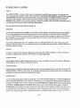
1.
BUTTERFLY
(15-125
Lbs.)
Muscles affected: pectoralls ma_or and minor, deltoids
ReFerto adjustment 2 on page 8 of thisowner's manual. Change the arms to the butlerfly mode. Sit on the seat and hold the pads on the arms as shown; your arms
should be bent at 90* angles. Keep your back straight. Press the arms together until
the pads touch. Returnto the starting position.
2.
BENCH
PRESS (30-250
Lbs.)
Muscles affected: pectoralis major and minor, anterior deltoids, triceps
Refer to adjustment 2 on Page 8 oF this owner's manual. Change the arms to the
press mode. Sit on the seat and hold the handles on the arms with an overhand grip.
Raiseyour elbows as shown. Keep your back straight. Fully extend your arms. Return
to the starting position.
3.
FRONT ARM RAISE (15-125
Lbs.)
Musclesaffected:
deltoids,rhomboids
ReFerto adjustment 4 on Page 9 of this owner's manual. Attach the strap to the low
pulley station. Stand with one heel on the foot plate. Hold the strap with an overhand
grip with your arm at your side. Keep your back straight. Raise I'hestrap until your
hand is level with your shoulder as shown. Return to the starting position.
4.
UPRIGHT
ROW (15-125
Lbs.)
Muscles affected: bkeps, deltoids, tropezlus
ReFerto adjustment 4 on Page 9 oFthis owner's manual. Attach the rower bar to the
low pulley station. Stand with your Feeton the foot plate. Hold the rower bar with an
overhand grip with your arms extended downward. Keep your back straight. Liftthe
rower bar untilyour hands are level with your chest as shown. Return to the starting
position.
5.
SHOULDER
SHRUG
('15-125
Lbs.)
Musclesaffected:trepezlus,rhomboids
Refer ta adjustment 4 on page 9 oFthis owner's manual. Attach the rower bar to the
low pultey station. Stand with your feet on the foot plate. Hold the rower bar with an
overhand grip with your arms extended downward. Keep your back strolghtand
your arms at your sides.Shrug your shoulders up as far as Possib/e. Return to the
starting position.
17
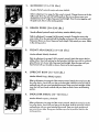
6.
LATERALARM
RAISE (15.125
Lbs.)
Muscles affec'_: deltoids,h'apezbs
Refer to adjustment4 on page 9 of this owner's manual. Attach the strap to the low
pulley station. Stand with your side toward the CROSS TRA)NER e with your Feeton
.
the Footplata. Hold the strop with an overhand grip with your arm at your side. Keep :_
your back straight. Raise the strap to the s[de until your hand is level with your shoulder as shown. Returnto the starting position.
7.
SEATED ROW--CLOSE GRIP (15-125
Lbs.)
Muscles affected: deltoids, tropezlus, biceps, broehioradials, latlssimus c/orsi
ReFerto adiuslment 4 on page 9 oFthis owner's manual. ,_tach the rower bar to the
low pulley station.Sit on the floor with your heels on the feat plate, lean forward,
extend your arms and hold the rower bar with an overhand grip. Pull the rower bar
toward your stomachand lean back, keeping your elbowsclose to your sides. Return
to the starting position.
8.
LAT PULL-DOWN--CHEST
(15-12S
Lbs.)
Muscles affected: laEssirnusdorsi, trapezlusl pectoralis moior
ReFerto adjustment3 on page 8 oF this ownerls manual. Attach the lot bar to the high pulley station. Sit on the seat facing the CROSS I"RAINER e. Extend your arms
upward and hold the Jarbar with an overhand grip. Keep your bacl_straight. Pullthe
lot bar down untll your hansd_"arelevel with your neck as shown. Ream to the starting position.
9.
LAT PULL-DOWN-BACK
(15-125
Lbs.)
Muscles affected:latissimus dorsi, trapezius
Refer to adiuslment3 on Page 8 oF this owner's manual A_Ch the lot bar to the
high pulley station. Sit on the seat Facing the CROSS TRAINER e. Extend your arms
upward and hold the lot bar with an overhand grip. Keep your back straight and
lean forward slightly. Pull the lot bar down behind your head until your hands are
level with your neck. Reksm to the starting position.
10.
HiP EXTENSION
(15-125
""
Lbs.)
Muscles affec?ed: gluteus maxlmus
ReFerto adjustment4 on Page 9 oFthis owner's manual. Attach the strap to the low
pulley station. Stand with one Footon the foot plate, lr'_ert one leg into the strap.
Keep your back straight. Keep your leg straight and move it backward as for as possible. Return to the starting p_s;tion.
18
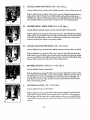
11.
LEG EXTENSION (15-125
Lbs.)
Muscles affected: quadriceps
Sit on the seat and position your feet under the pods on the leg developer. Keep your
back straight. Raise the leg developer unlflyour legs are straight. Return to the start_ngposition.
12.
HIP ABDUCTION
(15-125
Lbs.)
Musclesaffected:abductor,gluteusmedius
Refer to adjuslment4 on page 9 of _is owner's manual. Attach the strap to the low
pulley station. Stand with your side toward the CROSS TRAINER e with one foot on
the foot plate. Insertyour ou_ide leg into the strop. Keep your back straight. Keep
your leg straightand move it to the side as for as possible. Return to the star'ffng
position.
13.
BICEPS CURL (15-125
Lbs.)
Muscles affected: biceps, brochbradials
Refer to adjustment4 on page 9 oF this owner's manual. Attach the rower bar to the
• low pulley station. Stand with your Feeton the foot plate. Hold the rower bar with an
underhand grip with your arms extended downward. Keep your back straightand
your elbows close to your sides. Curl the rower bar up toward your chestas shown.
Return to the starting position.
14.
TRICEPS EXTENSION
(15-125
Lbs.)
Muscles affected: triceps, brachloradlals
ReFerto odiustment 3 on Page 8 at th_sowner's manual. Attach the rower bar to the
h_ghpulley station. Sit on the seat, hold the rower bar above your head and bend
your elbows. Keep your back straight and your elbows in. Slowly straightenyour
arms as shown. Return to the staffing position.
15.
TRICEPS PRESS-DOWN
(15-125
Lbs.)
Muscles affected: triceps, brachloradials
.?
Refer ta adjustment 3 on page 8 oFthis owner's manual. Attach the rower bar to the
high pulley station. Stand with your feet on the foot plate. Hold the rower bar with an
overhand grip with your hands at chest level. Keep your back straight and your
elbows close to your sides. Press the rower bar down until your arms are straight.
Return to the starting position.
19
16. SINGLE LEG CURL (15-125
Lbs.)
Muscles affected: hamstring, gastrocnem;us
Stand facing the CROSS TRAINER e and rest the back oFone leg against the lower _
pad on the leg developer. Ralse the leg developer as far as possible by bending your
leg as shown. Rel_rn to the starting position.
17.
AB CRUNCH
(15-125
Lbs.)
Musclesaffected:reclus abdominus, upper abdomlnals
Refer to adjustment 3 on page 8 of this owner's manual. Attach the strap _ the hlgh
pulley station. Sit on the seat and hold the strap behind your head as shown. Keep
your back straight. Slowly band forward at the waist untilyour upper body is at a
45* angle. Return to the starting position.
18.
BACK EXTENSION
(15-125
Lbs.)
Muscles affeded: hip extensors
Refer to adjustment 4 on page 9 of this owner's manual. Attach the.!ot bar to the low
pulley station.Sit an the floor with your heels on the foot plate. Cross your arms and
hold the lat bar against your chestas shown. Keep your back stralgh't.Bend back at
the waist. Relum to the starling position.
19.
WRIST
CURL (15-125
Lbs.)
Muscles affeded: brachioradials
Refer to adjustment 4 on page 9 of this owner's manual. Attach the rower bar to the
low pulley stotbn. Stand with your feet on the Footplate. Hold the rower bar with an
overhand grip with your arms extended downward. Keep your arms stationary and
curl your hands up as far as possible. Reksm to the stortlngposition.
20. TOE
RAISE (15-125
Lbs.)
Muscles affected: gostrocnemlus
Refer to adius_ent 4 on page 9 of thisowner's manual. Attach the rower bar to the
low pulley s/orion.Stand with your feet on the foot plate. Hold the rower bar with an
overhand grlp with your arms extended downward. Keep your back strgightand
your arms at your sides. Rise up on your toes as far as possible. Return to the stai_ng
position.
20
A.
SIDE BEND (15-125
Lbs.)
Musclesoff_ed: le_'ssimusdcrsi, biceps,posterior deltoids
• Referto adjustrne_nt
4 on page'9 of thisowner'smanual.Attach the strapto the low
pulleystation.Standwith your sldetoward the CROSSTRAINERe withone footon _
the footplate.Hold thestrapwith an overhandgrip with yourarm at your•side. Keep
your back straight.Bendtoward the sideas shown.Returnto the s_artingposition.
B.
LAT PULL-DOWN--CLOSE
GRIP (15-125
Lbs.)
Musclesaffected:lallsslrnusdorsl,biceps,posteriordeltoids
ReFerto odjus_ent 3 on page 8 of this owner's manual. A_ach the rower bar to the
high pulley station. Siton the ._eatfacing the CROSS TRAINER e. Extend your arms
upward and hold the rower/0or with an underhand grip. Keep your back straight.
Pull the rower bar down until your hands ore level with your neck. Return to the starting Position.
C.
SINGLE ARM CABLE FLY (15-125
Lbs.)
Muscles affected: latlsslmus dorsi, biceps, posterior deltoids
Refer to adjus_ent 3 on page 8 of this owner's manual. Attach the strap to the high
pulley station. Stand with your side toward the CROSS TRAINER e with one foot on
•the foot plate. Extend one arm upward and hold the strap. Keep your back straight.
Pull the strop down until your hand is level with your wolst. Return ta the starling
position.
D.
BENT ROW-WIDE
GRIP (15-125
Lbs.)
Musclesaffeded:biceps,brachbrad;als,deltoids,_pez[us, lallsslmusdorsi,rhomboids
Refer to odjuslment4 on page 9 oF this owner's manual. Altoch the let bar to the tow
pulley station. Stand with your feet on the foot plate and bend forward as shown.
Hold the lot bar with an overhand grip with your arms extended downward. Keep.
your back straight.Pull the lot bar toward your stomach.Return to the starting position.
E.
BENT ROW-CLOSE
GRIP (15-125
Lbs.)
Muscles affected: biceps, brachioradlals, dellolds,Irapezlus, lallssimus dorsi, rhomboids
Refer to odjush'nent4 on page 9 of this owner's manual. Attach the rower bar to the
low pufley station. Stand with your feet on the foot plate and I:_endforward as
shown. Hold the rower bar with an overhand grlp with your arms extended downword. Keep your back straight. Pull the rower bar toward your stomach. Return to
the starting posit;on.
21
F.
SINGLEARM
BENT ROW (15--125
Lbs.)
Muscles affected: biceps, brachioradlals, deltoids, tropezlus, laHsslmusdorsi, rhom,,oids
Refer to adjustment 4 on page 9 of this owner's manual. Attach the strap to the Iowlz
pulley stoHon.Stand with your feet on the foot plate and bend forward c_ shown. :'_ :
Hold the strap with an overhand grip with your arm extended downward. Keep your
back straight. Pull the strap toward your stomach. Return to the starting Pasltbn.
G.
SEATED ROW-WIDE
GRIP (15--125
Lbs.)
Musclesaffected: deltoids, tropezies,biceps, brochioradials, latissimus dorsi
Refer to adju:_tment4 on page 9 of this owner's manual. Attach the lot bar to the low
pulley station. Sit on the floor with your heels on the foot plate. Lean forward, extend
your arms and hold the lot bar with an overhand grip. Pull the lot bar toward your
stomach and lean back. Return to the starting position.
H.
SINGLEARM
SEATED ROW(15--125
Lbs.)
Muscles offecled: biceps, brachioradlals, deltoids, trapezlus, laHssimus:dorsi,
rhomboids
Refer to adjustment 4 on page 9 of this owner's manual. Attach the .',trap to the low
pulley station. Sit on the floor with your heels on the foot plate. Leanforward, extend
one arm and hold the strap._ull the strap toward your stomach and-ban back, keeping your elbow close to your side. Return to the starling position.
I.
REVERSE
BICEPS
CURL (15--125
Lbs.)
Muscles affected: biceps, brochloradials
Refer to adjustment 4 on page 9 of this owner's manual. Attach the rower bar to the
low pulley station. Stand with your heel on the foot plate. Hold the rower bar with an
overhand grip with your arms extended downward. Keep your back straight and
your elbows close to your sides. Curl the rower bar up toward your chest as shown.
Return to the staffing position.
J.
ISOLATION
CURL (15--125
Lbs.)
Muscles affected: biceps, brachlorodlals
Refer to adiustment 4 on page 9 of this owner's manual. Attach the strap to the low
pulley station. Stand with your side _oword the CRC _S TRAINER e with one Footon
the foot plate. Hold the strap with an underhand grip with your arm extended down
ward. Pull the strap up until your hand is level with your chest. Return to the starting
position.
22
K. _ BENT ISOLATION
Mu. .:es a_-'ted:
"
-
CURL (15--125
Lbs.)
biceps, _rachbradlals
Refer to adjustment 4 on page 9 of this owneds manual. Attach the strap to the low :
pulley s_tion. Stand with your side toward the CROSS TRAINER e, place one foot on
the foot plate and bend forward as shown. Hold the strap with an underhand grip i
with your elbow resting against your knee and your arm extended downward. Pull :
the strap up until your hand is level with your chest, Return to the starting Posit_on.
L.
REVERSEWRIST CURL (15--125
Lbs.)
Musclesaffected:brachloradials
Refer to adjustment4 on Page 9 of this owner's manual. Attach the rower.bar to the
low pulley station. Stand facing away Fromthe CROSS TRAINER • with your heels on
the foot plate. Hald the rower bar behind your back as shown. Keep your-arms stationary and curl your hands up as far as possible. Return to the starting position.
M.
REVERSE TRICEPS PRESS-DOWN
(15--125
Lbs.)
Muscles affected: triceps, brachioradials
Refer to adjustment3 on Page 8 of this owner's manual. Attach the rower bar to the
high pulley station. Stand with your feet on the foot plate. Hold the rower bar with an
underhand grip with your hands at chest level. Keep your back straightand your
elbows close to your sides. Pressthe rower bar down until your arms are straight.
Rehsrnto the starting position.
N.
SINGLE ARM TRICEPS PRESS-DOWN (15--125
Lbs.)
Muscles affected: triceps, brachbradials
Refer to adjustment3 on Page 8 of this owner's manual. Attach the strap to the high
pulley station. Stand with your feet on the foot plate. Hold the stropwith an overhand
grip with your hand at chest level. Keep your back straightand your elbow close to
your side, Pressthe strap down until your arm is straight as shown. Return to the
startingposition.
O.
REVERSE UPRIGHT
ROW
(15--125
Lbs.)
Muscles affected: biceps, deltoids, trapezius
Refer to adjustment 4 on page 9 of this owner's manual. Attach the rower bar Io the
Jaw pulley station. Stand facing away Fromthe CROSS TRAINER e with your heels on
the foot plate. Hold the rower bar behind your back with your arms extended downword. Lift the rower bar up as far as posslbJe. Rek_rn to the starling position.
23
P.
BENT LATERAL ARM RAISE (I 5-I 25 Lbs.)
Muscles affected: delto;ds,trapezlus
Refer to adjustment 4 on page 9 oF this owner's manual. Attach the strap to the low
pulley station. Stand withyour side toward the CROSS TRAINER e, place one foot on
the foot plate and bend forward as shown. Hold the strap with an overhand grip_
with your arm at your side. Keep your back straight. Raise the strop to the side until
your hand is level with your shoulder.Return to the starting position.
Q.
DEAD LIFT(15.125
Lbs.)
Muscles affected: quadrlceps
Refer to adjustment4 on Page 9 of this owner's manual. Altoch the lot bar tothelow
pulley:station. Stand with your feet on the foot plate and bend your knees as shown.
Hold the lat her with on overhand grip. Keep your head up and your arms and back
straight. Lift the lat bar by straightening your legs. Return to the starting positiGn.
R.
HIP ADDUCTION
(15-125
Lbs.)
Muscles affected:adductor, gluteusmedius
Refer to adjustment4 on Page 9 of this owner's manual. Attach the strap to the low
pulley station. Stand with your side toward the CROSS TRAINER e with one foot on
the Foot plate. Insert your inside leg into the strap. Keep your back straight. Keep
your leg straight and move it to the side as far as Passible. Return to the starting
position.
S.
FRONT KICK (15-125
Lbs.)
Musclesaffected:hipflexors,sartorlus
Refer to adjustment 4 on page 9 of this owner's manual. Attach the strap to the low
pulley station. Stand facing away from the CROSS TRAINER • with one heel on the
foot plate. Insert one leg into the strap. Keep your leg straight and move it away from
the CROSS TRAINER.• as far as possible. Return to the starting position.
STEPPER
Muscles Affected: ctuadriceps, hip extensors
(Note: Do not includethis exercise in workouts created with the PERSONALTRAINER
computer. When the STEPPERis used, the s;epper console will provide feedback.)
Refer to adiustment 1 on page 8 of this owner's manual. Hold the stepper ha,idle and
begln stepping, alternately pressing the left and right pedals down with o smooth,
continuous mo_io_
continuous motion must be maintalned or both pedals will sink
to the Floor.Adjust the stepping resistance if necessary.
24
ORDERING REPLACEMENT PARTS
EachCROSSTRAINERe has itsownMODELNUMBER.Always mentionthisMODEL NUMBERwhen requestingservice
or repairpa_ for your CROSSTRAINERe.
All Po_ listedherein can be orderedthrough SEARS,ROEBUCKAND CO. SERVICECENTERSand mostSEARS
RETAILSTORES.If paris you needore not slackedlocally, your orderwill be transmil_edto a SEARSPARTSDISTRIBUTION CENTERfor handling.
WHEN ORDERINGREPAIRPARTS,ALWAYS GIVETHEFOLLOWINGINFORMATION:
1. TheMODELNUMBERof the product (831.159341).
2. TheNAME of the product (PROFORM"CROSSTRAINERe).
3. ThePARTNUMBERof th_ Port(s)from the PARTUST/EXPLODED
DRAWING accompanyingthis Cwnedsmanual.
4. TheDESCRIPTION
of the port(s)from the PARTUST/EXPLODED
DRAWING accompanyingthis owner's manual.
Your SEARSmerchandisehasadded value when you considerthat SEARShas serviceunitsnationwide, stuffedwith
SEARStrained techniciansspecificallytrained on SEARSproducts,having the parts, toolsand equipmentto ensurethat
we meetour pledge to you: 'We servicewhat we sell."
Shouldyou everneedrepair serviceor Po_, calltoll-free:
Forrepairservice:1-800-4-REPAIR(1-B00-473o724_
Forrepair paris: 1-80a-FaN-PART(I-800-366-7278)
I
FULL 90 DAY WARRANTY
For90 days from the date of purchase,when proper assemblyand maintenance proceduresdetailed in the
owner's manual are followed, SEARSwill, free of charge, repair or replace and install a replocem.entpert for
any defective port, when the PROFORM" CROSSTRAINER e is used in a normal manner.
This warranly does not apply when the CROSSTRAINER e is used for commercial or rental purposes.
SERVICEIS AVAILABLESIMPLYBY CONTACTING YOUR NEARESTSEARSSERVICECENTER/DEPARTMENTIhi
THEUNITED STATES.
This warranly gives you specificlegal rights;you may also have other rights which _ry
_'om slate to slate.
SEARS,ROEBUCKAND CO., DEPT.817WA,
3333 BEVERLYROAD, HOFFMAN ESTATES,IL 60179
PartNo. 119390 R694A,
Printedin USA