1
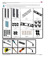
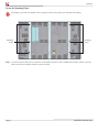
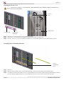
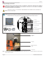
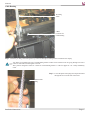
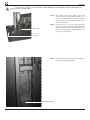
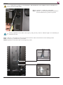
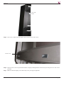
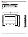
INSTALLATION INSTRUCTIONS
SCM-103
Suspended Ceiling Mount
NORTH AMERICA
3130 East Miraloma Avenue
Anaheim, CA 92806 USA
USA and Canada –
Phone: 800-368-9700
Fax: 800-832-4888
EUROPE
Swallow House,
Shilton Industrial Estate,
Shilton, Coventry, England CV79JY
Phone: +44 (0) 2476 614700
Fax: +44 (0) 2476 614710
Other Locations – Phone: (001)-714-632-7100; Fax: (001)-714-632-1044
©Premier Mounts 2008
9531-027-224-02
AUSTRALIA, NEW ZEALAND,
OCEANIA (DISTRIBUTOR)
P.O. Box 295
Mordialloc Victoria 3195
Australia
Phone: 039586 6330
www.premiermounts.com.au
SCM-103
Table of Contents
Warning Statements
Parts List
Installation Tools
Locating the Mounting Points
Mounting the Brackets to the Display
Securing the Lower Cover
Securing the Tubes to the Mounting Brackets
Lifting the Display into Position
Cable Routing
Installing the Beauty Covers
Technical Specifications
Warranty
2
3
3
4
5
6
6
8
9
12
14
15
Warning Statements
IT IS REQUIRED THAT THE INSTALLATION LOCATION BE INSPECTED AND APPROVED BY A
LICENSED STRUCTURAL ENGINEER.
PRIOR TO THE INSTALLATION OF THIS PRODUCT, THE INSTALLATION INSTRUCTIONS SHOULD BE READ AND COMPLETELY
UNDERSTOOD. THE INSTALLATION INSTRUCTIONS MUST BE READ TO PREVENT PERSONAL INJURY AND PROPERTY DAMAGE. KEEP
THESE INSTALLATION INSTRUCTIONS IN AN EASILY ACCESSIBLE LOCATION FOR FUTURE REFERENCE.
PREMIER MOUNTS DOES NOT WARRANT AGAINST DAMAGE CAUSED BY THE USE OF ANY PREMIER MOUNTS PRODUCT FOR
PURPOSES OTHER THAN THOSE FOR WHICH IT WAS DESIGNED OR DAMAGE CAUSED BY UNAUTHORIZED ATTACHMENTS OR MODIFICATIONS, AND IS NOT RESPONSIBLE FOR ANY DAMAGES, CLAIMS, DEMANDS, SUITS, ACTIONS OR CAUSES OF ACTION OF WHATEVER
KIND RESULTING FROM, ARISING OUT OF OR IN ANY MANNER RELATING TO ANY SUCH USE, ATTACHMENTS OR MODIFICATIONS.
THE SURFACE MUST BE CAPABLE OF SUPPORTING AT LEAST FIVE TIMES THE WEIGHT OF THE DISPLAY. IF NOT, THE CEILING
STRUCTURE MUST BE REINFORCED. THE MAXIMUM WEIGHT THAT CAN BE USED WITH THIS PRODUCT IS 2000LBS. PROPER
INSTALLATION PROCEDURE BY A QUALIFIED SERVICE TECHNICIAN, AS OUTLINED IN THE INSTALLATION INSTRUCTIONS, MUST BE
ADHERED TO. FAILURE TO DO SO COULD RESULT IN SERIOUS PERSONAL INJURY, OR EVEN DEATH.
SAFETY MEASURES MUST BE PRACTICED AT ALL TIMES DURING THE ASSEMBLY OF THIS PRODUCT. USE PROPER SAFETY GEAR
AND TOOLS FOR THE ASSEMBLY PROCEDURE TO PREVENT PERSONAL INJURY.
At least two qualified people should perform the assembly procedure. Injury and/or damage can result from dropping or mishandling the display.
If mounting to studs, make sure that the mounting screws are anchored into the center of the studs. Use of an edge-to-edge stud finder is recommended.
This product is intended for indoor use only. Use of this product outdoors could lead to product failure and personal injury.
Do not install near sources of high heat. Do not install on a structure that is prone to vibration, movement or chance of impact
Contact Premier Mounts with any questions
(800) 368-9700
[email protected]
Redundancy in Engineering is the duplication of critical components of a system with the intention of increasing reliability of the system, usually in the
case of a backup or fail-safe.
Page 2
Installation Instructions
SCM-103
Parts List
This ceiling mount is shipped with all proper installation hardware and components. Make sure that none of these
parts are missing and/or damaged before beginning installation. If there are missing and/or damaged parts, please
stop the installation and contact Premier Mounts (800-368-9700).
Mounting Brackets
(Qty 2)
Mounting Bracket Covers
(Qty 2)
Tubing
(Qty 3)
Lower Cover
(Qty 1)
Display Input Cover
(Qty 1)
8-32 x 1/2” Phillips Screws
(Qty 6)
Lower Cover Panel
(Qty 1)
Plastic Coupler Inserts
(Qty 4)
8-32 x 3/8” Phillips
Screws (Qty 18)
6-32 x 1/4” Set Screw
(Qty 4)
Clevis Pins
(Qty 6)
10-32 Kep Nut
(Qty 4)
Recommended Installation Tools
1/2” Socket and Wrench
Screwdriver
Spirit Level (Supplied)
1/8” Allen wrench (Supplied)
Tape Measure
Pencil
Stud Finder
1/16” Allen wrench (Supplied)
Installation Instructions
Page 3
SCM-103
Locate the Mounting Points
The display comes with four (4) M16 screws with quick release sleeves that are pre-installed on the display.
Mounting
Points
Mounting
Points
Step 1. Locate the 4 quick release sleeves on the back of the display and remove. Place the M16 bolts and split washers to the side.
These will be used for bracket installation on the next page.
Page 4
Installation Instructions
SCM-103
Mounting the Brackets to the Display
The following steps will require a minimum of 3 people. This should not be done with less then 3 people due to the
weight of mounting brackets.
Left Mounting
Bracket
Right Mounting
Bracket
Split Washer
M16 Bolt
Step 1. Align the mounting bracket holes up with the mounting holes on the back of the display. There are two mounting holes used on
each side of the display.
Step 2. Place the split washer between the display and the mounting bracket.
Step 3. Insert the M16 mounting bolt through the mounting bracket then through the split washer into the display.
Step 4. Tighten the bolt into place and repeat the steps for the remaining three bolts.
DO NOT OVERTIGHTEN THE M16 BOLTS. DOING SO MAY RESULT IN DAMAGE TO
THE DISPLAY. TIGHTEN TO MANUFACTURERS SPECIFICATIONS.
Installation Instructions
Page 5
SCM-103
Securing the Lower Cover
THE SCM-103 IS HEAVY. IT IS STRONGLY RECOMMENDED THAT THREE PEOPLE PERFORM ALL
INSTALLATION STEPS.
8-32 x ½”
Screw
10-32 Kep Nut
Lower Cover
Pre Installed
Handy Box
Step 1. Insert the lower cover between the vertical mounting brackets.
Step 2. Attach four (4) 10-32 Kep Nuts and tighten down securing the lower cover into place.
Step 3. Insert two (2) 8-32 x ½” screws and tighten down the lower cover bracket against the vertical side mounting brackets.
Securing Tubes to Mounting Brackets
Factory
Installed Set
Screw
Step 1. Slide the tubes into the cut outs on the side of the mounting brackets.
Step 2. Slide the tubes in enough to have an even amount showing on each side of the left & right mounting brackets.
Step 3. Once tubes are slid into place, tighten all twelve (12) pre-installed set screws located in the display mounting brackets using the
1/8” Allen wrench (supplied). These screws are installed at the factory and are used to lock the tubes into place.
Page 6
Installation Instructions
SCM-103
THE SCM-103 IS HEAVY. IT IS STRONGLY RECOMMENDED THAT THREE PEOPLE PERFORM ALL
INSTALLATION STEPS.
Clevis Pin
2” Tube
Cotter Pin
Step 5. Once the tubes are locked into place insert the clevis pins into the hole at the end of each tube.
Step 6. Lock each clevis pin into place by inserting the attached cotter pin into the hole.
Now that the mount is attached to the display, double check all mounting locations to insure all hardware is
properly tightened and secured.
Installation Instructions
Page 7
SCM-103
Lifting the Display into Position
IN THE NEXT STEP A LIFTING DEVICE SUCH AS A FORKLIFT , SCISSOR LIFT, OR HOIST WILL NEED TO
BE UTILIZED IN ORDER TO LIFT DISPLAY INTO POSITION. NOT DOING SO COULD RESULT IN PERSONAL INJURY OR DAMAGE TO THE DISPLAY.
THE SCM-103 IS HEAVY. IT IS STRONGLY RECOMMENDED THAT THREE PEOPLE PERFORM ALL
INSTALLATION STEPS.
The display may be hung from a ceiling structure using two (2) main support cables and two (2) safety cables. Length,
mounting location and method of attachment will be provided by the installer. The components (below) that are used
to hang the SCM-103 are sold separately and may be ordered through Premier Mounts (800) 368-9700.
1/4” Cable
1/4” Redundancy Cable
Support Bar
1/2-20 Hex Nut and Flat Washer
1/4” stainless steel 7 x 19 wire rope assembly w/
1/2” - 20 NF stainless steel threaded stud with
3-1/2” thread min. on one end only
1/2-20 Threaded Stud
Bracket Cover
1/2-20 Hex Nut and Flat Washer
1/2-20 Threaded Stud
1/2-20 NF hex nut
(Qty 18)
Flat Washer
(Qty 8)
1/4” Steel Thimble
Cable Access Channel
Pre-Hung
Cable
Fork Lift
Display Sucured to
Pallet
Scissor Lift
Step 1. Raise the display to the desired height (Refer to the display manufacturer specs on raising the display into position and the
different options available).
Page 8
Installation Instructions
SCM-103
Cable Routing
Pre-Hung
Cable
2 Hole
Locations for
Cable Routing
Step 1. Route the pre-hung cables through the top of the left and right mounting brackets attached to the display.
Two holes are provided at the top of each mounting bracket. Cables can be routed so both are going through one hole or
routed so each cable runs through its own hole.
The system is designed to allow for 2 cables on each mounting bracket. 1 cable for support & 1 as a safety redundancy
cable.
Step 2. Locate the plastic insert plugs and slip around cable
through the cut out in the side of the insert.
Plastic Insert
Plug
Installation Instructions
Page 9
SCM-103
THE SCM-103 IS HEAVY. IT IS STRONGLY RECOMMENDED THAT THREE PEOPLE PERFORM ALL
INSTALLATION STEPS.
Plastic Top
Step 3. Slide plastic insert plug down cabling and
insert into the top of the mounting bracket. A cut
out in the mounting bracket is provided that will
allow the plastic cap to sit flush with the top of
the mounting bracket
Step 4. Locate the 6-32 x 1/4” Set Screw and insert
into the sides of the plastic top locking the plastic
plug into position. The set screw location is on
the side of each plastic top. Tighten the set screw
using 1/16” Allen wrench.
6-32 x 1/4”
Set Screw
Step 5. Route the cable down through the provided holes
on the display mounting bracket.
Cable Routing Holes
Page 10
Installation Instructions
SCM-103
THE SCM-103 IS HEAVY. IT IS STRONGLY RECOMMENDED THAT THREE PEOPLE PERFORM ALL
INSTALLATION STEPS.
Step 6. Locate the ½”-20 Nuts & ½” flat washer.
Step 7. Measure 1 ¾” inches up the threaded stud attached to
the cable and thread one ½-20 nut into position.
Leveling adjustment can be made at this stage by setting the nut position at different heights on the threaded post
attached to the cable.
Step 8. Slide one ½” flat washer up to the nut and insert the end of the stud into the bottom hole of the mounting bracket.
Step 9. Locate two ½”-20 nuts & one ½” flat washer.
Step 10. Tighten the two nuts until cable is locked tight into position.
Installation Instructions
Page 11
SCM-103
Installing the Beauty Covers
8/32 x 3/8” Screw
Step 1. After all cables have been routed through mount and are properly installed, locate the display input cover panel.
Step 2. Install the panel by sliding it into position behind the tubes.
Step 3. Lock the cover into position by tightening the six (6) 8-3 x 3/8” screws.
Mounting Bracket
Cover
Step 4. Slide the mounting bracket covers into position.
Page 12
Installation Instructions
SCM-103
8-32 x 3/8”
Screws
Step 5. Once cover is slid into position tighten down using the 8-32 x 3/8” screws.
Lower Cover
Step 6. Drop the lower cover into position between the 2 display mounting brackets and lock into place using the 8-32 x 3/8” screws
provided.
Step 7. Make sure that the display is level and slowly lower your support equipment.
Installation Instructions
Page 13
SCM-103
Technical Specifications
All measurements are in inches(mm).
Page 14
Installation Instructions
SCM-103
Warranty
PREMIER MOUNTS
LIMITED LIFETIME WARRANTY
What and Who is Covered by this Limited Warranty and for How Long
Premier Mounts warrants this product to be free from defects in material and workmanship for the lifetime of
the original owner of this product. The limited warranty is valid only for the original purchaser of the product.
What Premier Mounts Will Do
At the sole option of Premier Mounts, Premier Mounts will repair or replace any product or product part that is
defective. If Premier Mounts chooses to replace a defective product or part, a replacement product or part will
be shipped to you at no charge, but you must pay any labor costs.
What is Not Covered; Limitations
PREMIER MOUNTS DISCLAIMS ANY LIABILITY FOR DAMAGE TO MOUNTS, ADAPTERS, DISPLAYS, PROJECTORS, OTHER PROPERTY, OR PERSONAL INJURY RESULTING, IN WHOLE OR IN
PART, FROM IMPROPER INSTALLATION, MODIFICATION, USE OR MISUSE OF ITS PRODUCTS.
PREMIER MOUNTS DISCLAIMS ALL OTHER WARRANTIES, EXPRESS OR IMPLIED, INCLUDING
WARRANTIES OF MERCHANTABILITY AND FITNESS FOR A PARTICULAR PURPOSE. PREMIER
MOUNTS IS NOT RESPONSIBLE FOR INCIDENTAL OR CONSEQUENTIAL DAMAGES, INCLUDING BUT NOT LIMITED TO, INABILITY TO USE ITS PRODUCTS OR LABOR COSTS FOR REMOVING AND REPLACING DEFECTIVE PRODUCTS OR PARTS. SOME STATES DO NOT ALLOW THE
EXCLUSION OR LIMITATION OF INCIDENTAL OR CONSEQUENTIAL DAMAGES, SO THE ABOVE
LIMITATION OR EXCLUSION MAY NOT APPLY TO YOU.
What Customers Must Do for Limited Warranty Service
If you discover a problem that you think may be covered by the warranty you MUST REPORT it in writing to
the address below within thirty (30) days. Proof of purchase (an original sales receipt) from the original consumer purchaser must accompany all warranty claims. Warranty claims must also include a description of the
problem, the purchaser’s name, address, and telephone number. General inquiries can be addressed to Premier
Mounts Customer Service at 1-800-776-5768. Warranty claims will not be accepted over the phone or by fax.
Premier Mounts
Attn: Warranty Claim
3130 East Miraloma Ave.
Anaheim, CA 92806
How State Law Applies
THIS WARRANTY GIVES YOU SPECIFIC LEGAL RIGHTS, AND YOU MAY ALSO HAVE OTHER
RIGHTS WHICH VARY FROM STATE TO STATE.
Installation Instructions
Page 15