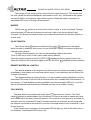
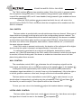
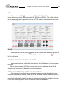
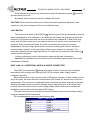
1
EF-202/204 DUAL/FOUR CHANNEL MASTER STATION E-200 SERIES CABLE INTERCOM SYSTEM OWNERS MANUAL PRELIMINARY ISSUE 16/04/2012 AUDIO ELECTRONICS DESIGN EQUIPOS EUROPEOS ELECTRÓNICOS, S.A.L Avda. de la Industria, 50. 28760 TRES CANTOS-MADRID (SPAIN). 34-91-761 65 80 34-91-804 43 58 www.altairaudio.com [email protected] EF-202/EF-204 MASTER STATION – E200 SERIES 2 1. INTRODUCTION.................................................................................................................................................4 2. SWITCHES, CONTROLS, ADJUSTMENTS AND CONNECTORS.........................................................................5 FRONT PANEL..................................................................................................................................................5 REAR PANEL.....................................................................................................................................................6 3. WORKING PRECAUTIONS................................................................................................................................7 4. INSTALLATION..................................................................................................................................................7 UNPACKING ...................................................................................................................................................7 MOUNTING......................................................................................................................................................7 CHANGING THE FUSE......................................................................................................................................7 CONNECTING TO THE MAINS.........................................................................................................................8 PROGRAM INPUT CONNECTION.....................................................................................................................8 UNBALANCED INPUT:.................................................................................................................................................. 9 BALANCED INPUT:...................................................................................................................................................... 10 PA OUTPUT CONNECTION.............................................................................................................................10 UNBALANCED OUTPUT:.............................................................................................................................................. 11 BALANCED OUTPUT:.................................................................................................................................................. 12 RELAY CONNECTION......................................................................................................................................12 EXTERNAL SPEAKER CONNECTION................................................................................................................13 CONNECTION TO EXTERNAL INTERCOM UNITS.............................................................................................13 MULTICHANNEL OPERATION. AUDIO LINKS.................................................................................................14 GENERAL PURPOSE INPUT / OUTPUT CONNECTIONS (GPIO).......................................................................15 SYSTEMS WITH MORE THAN 50 WIRED BELTPACKS....................................................................................16 INTERCOM LINE CONNECTIONS – 4W MODE................................................................................................17 5. OPERATION.....................................................................................................................................................17 PANEL MIC CONNECTION..............................................................................................................................18 HEADSET CONNECTION.................................................................................................................................18 HEADSET SIDETONE CONTROL......................................................................................................................19 HEADSET VOLUME CONTROL........................................................................................................................19 PANEL MIC GAIN CONTROL...........................................................................................................................19 PANEL MIC SWITCH.......................................................................................................................................19 REMOTE MIC KILL SWITCH.............................................................................................................................19 BUZZER..........................................................................................................................................................20 PA OUT SWITCH............................................................................................................................................20 REMOTE BUZZER KILL SWITCH ....................................................................................................................20 TALK SWITCH ...............................................................................................................................................20 CALL SWITCH.................................................................................................................................................21 NULL CONTROL..............................................................................................................................................21 LISTEN LEVEL CONTROL..................................................................................................................................21 MEMORIES ....................................................................................................................................................22 PROGRAM INPUT ON SWITCH......................................................................................................................22 PROGRAM INPUT LEVEL CONTROL...............................................................................................................22 PROGRAM TO HEADPHONES CONTROL......................................................................................................22 USB................................................................................................................................................................23 PROGRAM OUTPUT GAIN CONTROL ...........................................................................................................23 PROGRAM INPUT MIC/LINE LEVEL SELECTOR...............................................................................................23 INTERCOM LINE TERMINAL IMPEDANCE DIP SWITCHES..............................................................................23 LINK SWITCH.................................................................................................................................................24 EASY LINK. ALL INTERCOM LINES IN A SINGLE CONNECTOR.......................................................................24 6. INTERNAL CONFIGURATION SETTINGS..........................................................................................................25 SETTING THE PROGRAM INPUT SEND AND THE PROGRAM INTERRUPT.....................................................25 INTERNAL CONFIGURATION SETTING...........................................................................................................26 PANEL MIC KEY MODE............................................................................................................................................... 27 PA OUT KEY MODE..................................................................................................................................................... 27 EXTERNAL MIC KILL & BUZZER KILL........................................................................................................................... 27 LOCAL BUZZER ACTIVATION BY:.............................................................................................................................. 28 EF-202/EF-204 MASTER STATION – E200 SERIES 3 HEADSET MICROPHONE TYPE (PHANTOM)............................................................................................................. 28 HEADSET MICROPHONE TYPE (GAIN)....................................................................................................................... 28 PANEL MIC KEY MODE: SINGLE OR DUAL MIC........................................................................................................ 28 BUZZER LEVEL............................................................................................................................................................. 28 PROGRAM IN TO PA/SA OUT................................................................................................................................... 28 PARTY LINE A TO PA/SA OUT.................................................................................................................................... 29 RELAY ACTIVE BY TALK B,C,D → ONLY EF-204 DIRECT ACCESS (*)......................................................................... 29 CALL SEND WHEN PRESSING TALK KEYS → ONLY EF-204 DIRECT ACCESS (*)...................................................... 29 LISTEN ON WHEN PRESSING TALK KEYS → ONLY EF-204 DIRECT ACCESS (*)....................................................... 29 LISTEN ON WHEN INCOMING CALL → ONLY EF-204 DIRECT ACCESS (*).............................................................. 29 RELAY ACTIVE BY PA OUT KEY................................................................................................................................... 30 RELAY ACTIVE BY TALK A KEY.................................................................................................................................... 30 TALK KEY MODE......................................................................................................................................................... 30 CALL/TALK KEYS INVERTED FUNCTION..................................................................................................................... 30 7. BLOCK DIAGRAM............................................................................................................................................31 8. TECHNICAL SPECIFICATIONS.........................................................................................................................32 9. WARRANTY...................................................................................................................................................33 PACKAGE CONTENTS: -THIS OWNERS MANUAL -1x EF-204 4 CHANNEL INTERCOM BASE STATION -1x GOOSNECK MICROPHONE -1x MAINS PLUG EURO OR UK MODELS -4x PAPER ADHESIVE CALL LABELS -4x TRANSPARENT TALK LABELS -4x RUBBER FEET EF-202/EF-204 MASTER STATION – E200 SERIES 4 1. INTRODUCTION Congratulations on your purchase of the ALTAIR master station EF-202/EF-204 of the E-200 series intercom system. There is a lot the characteristics that make of the ALTAIR E-200 series one of the most highlighted in the audio professional market, some are enumerated here: The Master station unit includes the power supply for all the intercom components in the system. In the case of short circuit on any point of the line, the unit shuts down with an instantaneous recovery after the fix is cleared. System can drive up to 60 single channel beltpacks or 20 desk stations. Separated four channels are provided with independent Talk, Listen, and Call signalling buttons. Linking between channels is made easy from the front panel buttons. All the components in the system incorporates digital control to implement different task as Mic Kill, remote buzzer switch-off, latch or PTT mic switching, etc. The station incorporates program input (mic/line) with level attenuator assignable to any of the four channels and mic output to address PA messages from the headset operator. Relay contacts are provided that follows the PA button action, helping the installer to automate multiple tasks as Tally, speaker switching and cue lights among others. The station can be used as a Main station driving all the system or as a desk remote console station in complex multipoint multichannel installations. One block of four key buttons allows the unit to be preset for instant recall of programmed set-up including Talk, Listen and Call key functions to any channel combination in an intuitive manner. Front panel includes gooseneck panel microphone, headset connection and a high efficiency speaker. Before beginning it is important to read this manual. This manual will help you to install and use your new intercom master station. It is very important to read it carefully, mainly the paragraphs marked as NOTE, PRECAUTION and DANGER, for your security. Save the original packing, you can re-use it to transport the unit. NEVER SHIP THE ALTAIR EF-202/EF-204 WITHOUT ITS ORIGINAL PACKING. EF-202/EF-204 MASTER STATION - SERIE E-200 5 2. SWITCHES, CONTROLS, ADJUSTMENTS AND CONNECTORS These are the switches, controls, adjustments and connectors that you can find in your ALTAIR intercom master station. The description and explanation of each one will be found in the corresponding section. FRONT PANEL EF-202/EF-204 MASTER STATION - SERIE E-200 REAR PANEL 6 EF-202/EF-204 MASTER STATION – E200 SERIES 3. WORKING PRECAUTIONS The manufacturer is not responsible of any damage that can possibly happen to the intercom master station outside the limits of the warranty or those produced by not taking care with the working precautions. Mains voltage must be between the limits of the admitted power supply (90-264 VAC, 50-60 Hz) and that the fuse must be the appropriate (2A slow blow type: T2A). Damage caused by connection to improper AC voltage is not covered by any warranty. DANGER: Inside the unit there are high voltages, do not open it. The unit does not contain elements that could be repaired by the user. Whenever the intercom master station is connected to the mains, it carries elements with high voltages. In order to disconnect the unit completely, you must disconnect it from the mains. CAUTION: Protect the unit from the rain and moisture. Ensure that no objects or liquids enter it. If liquid is spilled into the unit, disconnect it from the mains and consult a qualified service technician. Do not place the unit close to heat sources. 4. INSTALLATION UNPACKING Before leaving the factory, each intercom master station has been carefully inspected and tested. Unpack and inspect the unit for any damage that may have occurred during shipment. If any damage is found, does not connect the unit to the mains; notify the salesperson immediately; a qualified service technician should inspect the unit. Save the original packing, you could use if you need to transport the unit. NEVER SHIP THE INTERCOM MASTER STATION WITHOUT ITS ORIGINAL PACKING. MOUNTING It is always recommended to mount the unit in rack, either for mobile or fixed installations, for protection, safety, aesthetics, etc. The ALTAIR EF-202/EF-204 is designed for standard 19" rack mounting, and takes up 1u high rack space. CHANGING THE FUSE This unit incorporates an internal, worldwide voltage operation power supply, and it is prepared to work from 90 to 264 VAC, 50-60Hz. 7 8 EF-202/EF-204 MASTER STATION – E200 SERIES Make sure that the unit is disconnected from the mains. In the unit rear panel are placed the mains connector and the fuse holder bellow this mains connector is called fuse holder. Take out the fuse holder. 24 . The box After extracting the fuse holder, the fuse will appear, take out it and change for the new one. Insert the fuse holder into the mains connector again. Make sure that the fuse is the right one: 2A slow blow type – T2A. CAUTION: Always make sure after changing the fuse, that it is the right one. CONNECTING TO THE MAINS The connection of the intercom master station power supply to the mains takes place by a standard cord included in the box. Make sure that the unit power switch 23 is at 0 position (turned off). Insert the female I.E.C. connector of the tripolar cable into the unit power supply male connector 24 , placed at the rear panel. Insert the male connector of the tripolar cable into the mains plug. Turn on the unit power switch 23 . In that moment the LEDs indicators will light, indicating that the unit is turned on. CAUTION: Make sure that the mains voltage is the correct as well as their fuse is the right one. PROGRAM INPUT CONNECTION The intercom master station program input signal is carried out through a XLR-3-31 female connector 30 . The input connection is balanced, with a nominal impedance of 40 KΩ (20 KΩ unbalanced) in line mode and 2 KΩ (1 KΩ unbalanced) in mic mode. The next list shows the input pins correspondence as A.E.S recommends: PROGRAM INPUT XLR-3-31 PIN 1 0V PIN 2 HOT (+) PIN 3 COLD (-) EF-202/EF-204 MASTER STATION – E200 SERIES 9 The input connection depends on two factors, the first is the type of input signal balanced or unbalanced, and the second the ground configuration of the sound source (floating or ground-referenced). The next pictures show some of the different possibilities of connection, relying on the type of input signal, balanced or unbalanced and according to the ground configuration of the equipment (floating or ground-referenced). In the next diagrams, we use the following symbols: Sound source with mains cord without ground connection. Sound source with mains cord with ground connection. Sound source with the EARTH-LINK OFF. Sound source with the EARTH LINK ON. UNBALANCED INPUT: This type of connection will be used when the sound source does not provide balanced output. If it’s possible it is better using the connection type 1 1) Using twin-lead shielded cable: EF-202/EF-204 PROGRAM INPUT EF-202/EF-204 PROGRAM INPUT EF-202/EF-204 MASTER STATION – E200 SERIES 2) Using single conductor shielded cable: 10 EF-202/EF-204 PROGRAM INPUT EF-202/EF-204 PROGRAM INPUT EF-202/EF-204 PROGRAM INPUT BALANCED INPUT: EF-202/EF-204 PROGRAM INPUT PA OUTPUT CONNECTION The PA and SA output signal is carried out through a XLR-3-32 male connector 27 . The output is balanced, with a nominal impedance of 100 Ω. The next list shows the input pins correspondence as A.E.S recommends: PA OUTPUT XLR-3-32 PIN 1 0V PIN 2 HOT (+) PIN 3 COLD (-) EF-202/EF-204 MASTER STATION – E200 SERIES 11 The output connection depends on two factors, the first is the type of input signal balanced or unbalanced, and the second the ground configuration of the sound destination unit (floating or ground-referenced). The next pictures show some of the different possibilities of connection, relying on the type of output signal, balanced or unbalanced and according to the equipment’s ground configuration (floating or ground-referenced). In the next diagrams, we use the following symbols: Sound destination unit with mains cord without ground connection. Sound destination unit with mains cord with ground connection. Sound destination unit with the EARTH-LINK OFF. Sound destination unit with the EARTH LINK ON. UNBALANCED OUTPUT: This type of connection will be used when the sound destination unit does not provide a balanced input. If it’s possible it is better using the connection type 1. 1) Using twin-lead shielded cable: EF-202/EF-204 PA OUTPUT EF-202/EF-204 PA OUTPUT 2) Using single conductor shielded cable: EF-202/EF-204 PA OUTPUT 12 EF-202/EF-204 MASTER STATION – E200 SERIES EF-202/EF-204 PA OUTPUT BALANCED OUTPUT: EF-202/EF-204 PA OUTPUT EF-202/EF-204 PA OUTPUT RELAY CONNECTION Base unit allows the control of an internal general relay 31 allowing control over an external device or application. Activation is controlled either with the PA function 9 or by the Mic A 11 or Mic B, C and/or D 11 front panel keys. Typical application of relay control is the command of the PTT key in radio transceivers, motor controllers, tally lights, etc. The connector type is an standard stereo 3.5 mm mini jack. Following table shows the connection diagram. RELAY COMMON NORMALLY CLOSED NORMALLY OPEN JACK 3/2” RING TIP SLEEVE TIP. RING. SLEEVE. The relay operation mode is configured by an internal preset. Factory set to PA, but it is possible configure it to activate the Mic A 11 or Mic B, C and/or D 11 with internal presets. NOTE: Relay operation is changeover type: When the function is not active, the Ring pole is connected to the Tip ant the Sleeve is opened. When active, Ring connects to the Sleeve and Tip becomes opened. 13 EF-202/EF-204 MASTER STATION – E200 SERIES EXTERNAL SPEAKER CONNECTION In the master station rear panel is available a connector to plug an external speaker 32 , which allows us to monitor the internal speaker 22 in an external speaker. The external speaker connection is via a 3.5 mm jack connector. The following table shows the correspondence of the connector pins with the external speaker jack 3.5 mm: EXTENAL SPEAKER CONNECTOR SIGNAL WHITOUT CONNECT GND JACK 3/2” TIP RING SLEEVE TIP. RING. SLEEVE. CONNECTION TO EXTERNAL INTERCOM UNITS The external units connection to the base station is carried through twin-lead standard microphone shielded cable and XLR-3-31/XLR-3-32 connectors 37 . Each base station channel provides one XLR-3-31 and one XLR-3-32 connectors wired internally in parallel. The next list shows the signal distribution in the pin XLR connectors. XLR-3-31/XLR-3-32 – INTERCOM LINE PIN 1 GND PIN 2 +VCC PIN 3 SIGNAL Certain rules have to be followed when installing the cables of an intercom system. This is to avoid ground loops and to minimize the power loss and possible effect of electromagnetic fields. Do not connect the XLR pin 1 to the XLR metal housing or to metal wall boxes to avoid ground loops. The ground loop could increase notably the system background noise. Do not close the intercom line connection (avoid closed loops). Each intercom line leaves from the base station towards the remote stations, but it does not return to the master station. If the connection is closed, a ground loop with the increase from the system noise will take place. Use high quality cables and minimize its longitude. Avoid using low quality cables and excessive cable runs as it affects in power loss, channel crosstalk and frequency response. Place the base station in the closest possible position to the maximum consumption zone; that is to say to the zone in which more external units are placed. 14 EF-202/EF-204 MASTER STATION – E200 SERIES The next picture shows the habitual connection of an intercom system comprised by eight beltpack units (two per channel) and a EF-204 base station. MULTICHANNEL OPERATION. AUDIO LINKS. Rear panel audio links allows multichannel operation sharing the headset between bases, so accessing all the channels. Connection is made by using two leads composed of 2 stereo 3,5 mm jacks at each end wired in inverted mode and by using miniature 2 conductors plus shield microphone cable. See the diagram bellow for reference. JACK 3,5 mm – MULTICHANNEL SYSTEM UNIT A UNIT B TIP RING RING TIP SLEEVE SLEEVE TIP. RING. SLEEVE. EF-202/EF-204 MASTER STATION – E200 SERIES 15 Schematic diagram: System operation is strait forward. You can connect your headset 1 , 2 to any of the bases. Microphone signal from the preamp out of the base #2 is directed to the preamp input in base#1. Channel Mic A,B,C and D 11 on/off switches from base#2 corresponds now to channels E, F, G and H respectively. Listening from the eight channels are controlled by local volume 14 and listen level controls 15 as depicted in this manual, A, B, C and D on base#1 and E, F, G and H on base#2. Call signalling 12 , remote mic kill 7 and buzzer kill 10 are to be controlled on each base independently. Program input signal must be splitted to each base if needed. PA outputs from the two bases must be combined externally by using an audio mixer and then connected to the PA system. These audio links allows advanced functionalities: Mic link-Direct microphone out, Mic input from external equipment, etc. EAR link-Listen connection to external powered speakers, cue input to the operator, etc. GENERAL PURPOSE INPUT / OUTPUT CONNECTIONS (GPIO) EF-202/EF-204 base station, have two general purpose inputs and two general purpose outputs allowing remote control from/to auxiliary equipment to/from the base station. These GPIO´s employs standard connectors (3.5 pitch) Phoenix ™ type . The inputs are logical, with an internal pull-up of 5 Volts and 100 KΩ, and therefore the simplest assembly is a simple switch to ground. Assemblies can also be connected to an open collector output. EF-202/EF-204 MASTER STATION – E200 SERIES SWITCHES TO GROUND 16 OPEN COLLECTOR The general purpose inputs can control all the buttons on the base station, make a general call to all lines, cause a Mic Kill or enable/disable the Buzzer Kill. By default the base station is configured with input 1 as the PANEL MIC 6 button, and input 2 can cause a general call (simultaneous CALL to CH A, B, C and D). The outputs are open collector, so we can feed to other power circuits provided (50 Volts DC maximum). In the output connector is available a supply of 5 volts DC to power the open collector circuit, this power is limited to 100 mA. The outputs can be connected to LEDs indicators, DC relays, among others. LED LAMPS DC RELAY CONTROL To general-purpose outputs can send the state of all buttons of the base station, the general call to all lines, the Mic Kill or the Buzzer Kill. By default the base station is configured with output 1 as the state of Mic Kill, and output 2 to the general call state. The configuration of the general purpose inputs and outputs can not be done directly from the base station front panel; instead it is necessary a USB connection to a PC running the free Altair EF-204 control software. Configuration is saved on the unit. SYSTEMS WITH MORE THAN 50 WIRED BELTPACKS It is possible to connect two master stations (EF-202/EF-204) in installations where it is necessary more than 50 wired beltpacks (EM-201), with their lines in parallel (A with A and/or B with B and/or C with C and/or D with D), always having the caution of opening the terminal impedance (in order to obtain more information, consult the terminal impedance switch/selector section 34 ), of the secondary master station lines that serves us simply as intercom line power reinforcement. In this type of operations, the master station unit is connected at the beginning of the intercom chain, and the secondary unit at the end of this line. In this way we will reinforce the beltpack units placed at the further positions. For this purpose, it is also possible to use the Altair PS-200 power supply unit. 17 EF-202/EF-204 MASTER STATION – E200 SERIES INTERCOM LINE CONNECTIONS – 4W MODE The base station includes 2x (EF-202) / 4x (EF-204) intercom lines. Each line comprises two connectors for gender convenience: one XLR3 male and one XLR3 female internally paralleled. Intercom line is defined as 2 wire mode (2W) enabling direct connection to similar 2W intercom equipments. To connect with 4-wire (4W) equipments, we recommend the use of an Altair 4W2-200 interface per intercom line (channel). However, you can set the channel A in 4W mode by following the next steps: Insert the (4W-IN) input signal in the program input connector 30 . Enable the input program in the correspondent channel (see section: BASE STATION INTERNAL ADJUSTMENT SETTINGS). Adjust the input program level activate the program input. 18 and press the program input on button 17 to Adjust the null control 13 of the corresponding channel to cancel the microphone in the headset 2 and speaker 22 . Enable the internal configuration PARTY LINE TO PA/SA OUT (see section: BASE STATION INTERNAL ADJUSTMENT SETTINGS). Disable the internal configuration PROGRAM IN TO PA/SA OUT (see section: BASE STATION INTERNAL ADJUSTMENT SETTINGS). If you want to transmit also the base station operator microphone to 4W output, press the PA activation button 9 and enable Pa out KEY MODE PTT & LATCH (see section: BASE STATION INTERNAL ADJUSTMENT SETTINGS). The signal (4W-OUT) goes out by the PA output 27 . 5. OPERATION The E-200 series intercom system are designed to allow maximum easy communication operations between the different control areas in music or theatre live performances, television, cinema, conference halls, and whatever broad events where multiple and fast communications are required, by means of its simultaneous listening-speaking operation system. The EF-202 and EF-204 system master station provides two and four independent intercom channels, and the capacity to feed up to 50 beltpacks (EM-201) in total distributed EF-202/EF-204 MASTER STATION – E200 SERIES 18 among all intercom channels. Each channel provides a CALL switch 12 , a MIC on/off switch (TALK) 11 , a LISTEN on/off switch 14 , and a listen level control 15 that allows to listen to the channels independently, or a mix between the channels. The program input allows to insert external audio signals in the intercom system. The external audio signals could be sent to each channel or to the headphones, independently. The headset microphone signal is available to drive external P.A. systems. Relay contacts are provided that follows the P.A. key action 9 , helping the installer to automate multiple tasks as Tally, switching speakers, cue lights, etc. System Expandability permits creating a multichannel (8, 12, or more channels) intercom System by using more Master Stations in a daisy chain arrangement. This feature enables freedom in System design and in-site future upgrades. Rental companies can benefit in lower component inventories. The global all mic (Mic-Kill) and buzzers (Buzz-Kill) mute systems in both channels, allows to control the line noise due to many open mics in the system, as well as the ambient silence. PANEL MIC CONNECTION There is a 4-pin XLR-4M connector (XLR-4-32) 1 , to connect a dynamic microphone gooseneck type to the base station. Electret mics are not allowed. The microphone gain is adjustable by a potentiometer (PANEL MIC GAIN) 5 between +20 and +50 dB. The following table shows the XLR correspondence Pin: XLR-4-32 – PANEL MIC PIN 1 0 V (MICROPHONE) SIGNAL (MICROPHONE) PIN 2 HEADSET CONNECTION A XLR-4 type connector (XLR-4-32) connector 2 , allows connecting a headset with microphone to the master station. The headset impedance must be 200 Ω or higher (up to 2 KΩ) and the microphone must be dynamic or electret type. The microphone preamplifier gain can be configured with an internal preset in +30 or +40 dB. (Factory set-up adjusted to +40 dB) For the electret microphone type it is necessary to enable the phantom power of 9 VDC with an internal preset. In order to obtain more information, consult the base station internal adjustment settings section. The next list shows the XLR pins correspondence: PIN 1 PIN 2 PIN 3 PIN 4 HEADSET XLR-4-32 0 V (MICROPHONE) SIGNAL (MICROPHONE) 0 V (HEADPHONES) SIGNAL (HEADPHONES) EF-202/EF-204 MASTER STATION – E200 SERIES 19 NOTE: Headsets are of the double or single muff type. In case of using a double muff headset, the two speakers should be wired in parallel. HEADSET SIDETONE CONTROL The headset sidetone control 3 adjusts the level of your own voice as you hear it in your headphones. Prior to use the Sidetone control, a good null of the four lines must be done. See next paragraph NULL CONTROL description. When the null has been done in all the used channels, your own voice is almost inaudible on the headset at minimum sidetone setting. Side tone is mainly used when you wear double muff headsets models so being very isolated from the outside ambient and also from your own voice. This causes an undesirable overmodulation of your voice to the others party. An adequate sidetone regulation allows a comfortable voice modulation and talk level to the intercom system. When using single muff headsets, the settings of the sidetone control are normally lower than using double muff. HEADSET VOLUME CONTROL The volume control 4 allows attenuating or amplifying the signal sent to the headphones. This control adjusts the listen level to the headphones. PANEL MIC GAIN CONTROL The panel microphone gain is adjustable by a potentiometer 5 between +20 and +50 dB. PANEL MIC SWITCH The panel mic button, allows enable the panel microphone 6 . Internal presets can be configured to allow this key to toggle between panel mic and headset mic 2 or headset mic always on (factory default). You can also configure the operating mode of the switch: Push to talk only, disabling latch operation or push to talk + latch mode. On this mode, push to talk or latch is recognized by the time the key is depressed. Short keystroke produces latch action and long time, momentary action. (factory default). REMOTE MIC KILL SWITCH These switch 7 allows to disable -switch OFF- all the microphones from all the channels around the intercom system (including all the wired and wireless beltpacks, desk station units and master station slave units) except the base station microphone.. EF-202/EF-204 MASTER STATION – E200 SERIES 20 The remote mic kill switch carries out the function upon pressing it. This means that the units (wired and wireless beltpacks, desk stations units, etc.) connected to the system can switch ON the microphones again when required. When this switch is pressed, its associated LED turns on during a short moment. BUZZER The Buzzer 8 , produces a sound when a call is made, or a key is pressed. Through internal presets you can set the buzzer sound level, high or low (factory default) and configure if the buzzer is turned off when you enable remote buzzer kill (factory default) or to work ever. PA OUT SWITCH The PA out switch 9 allows to enable the PA output 9 placed at the rear panel, which normally is disabled, and to carry out the HEADSET/PANEL microphone signal to A external audio systems. Through internal presets, you can set the operating mode of the switch: -Push to talk only or push to talk +latch mode (factory default) -Send the program signal to the PA OUTPUT 27 (disabled is factory default) and/or the -Send the intercom line Channel A signal to the PA OUTPUT 27 (disabled is factory default) REMOTE BUZZER KILL SWITCH This switch disables all the buzzers from all the intercom system channels (including all beltpacks, desk station units and base station units). Local operators are not able to turn on again its buzzers. This button performs a rotating function. If it was enabled, pressing disabled it and the associated LED turns off (at this time all external units can re-enable their local buzzers), on the contrary, if it was disabled, pressing enabled it and the associated LED turn on (at this time all the external units buzzers are disabled and can not re-enable it locally). TALK SWITCH The base station is provided with a talk switch 11 per intercom channel. The TALK switch 11 allows to enable/disable the microphone, so that we are able to speak with other units connected to the same intercom channel. If the channel A microphone is activated (for example), and the channels B,C and D microphones are not activated, we will speak with the stations connected to the channel A, but the connected stations to the channel B, C and D won’t hear us. If the microphone is activated, its associated LED will light up, and on the other hand, if it is disabled, its associated LED will turn off. 21 EF-202/EF-204 MASTER STATION – E200 SERIES The TALK switches 11 have two operation modes. When this switch is pressed quickly, the microphone changes its state; if it was enabled, being pressed it gets disabled and turns off the associated LED, and if it was disabled, being pressed it gets enabled and turns on the associated LED. When the TALK switches 11 are pressed and held, the unit will enter in the special function PUSH TO TALK; this means that the microphone will be enabled until the switch is released. CALL SWITCH The base station is provided with one call switches per intercom channel. When one of these switches is pressed a call signal is sent to the corresponding intercom channel. The call signal makes the LED associated with the switch start blinking; if the buzzer is enabled an intermittent sound takes place and the correspondent LED blink, during three seconds, the same as in all the units (beltpacks, desk stations, master stations, etc.), connected to the same intercom channel. If the CALL switch is pressed continuously, the duration of the call signal will be higher (the time that the switch is pressed, and approximately 3 seconds more). If a call signal is generated in an external unit (beltpacks, desk stations, master stations, etc.), the LED associated to the CALL switch of the channel in which the call signal is received, will start blinking and if the buzzer is enabled an intermittent sound will take place during about three seconds. NULL CONTROL The cancellation control (NULL) 13 , eliminates the self microphone signal from the listen signal, so that there are no unwanted coupling to the speaker 22 or to the headset 2 Is designed so that approximately half of travel of the potentiometer produces the microphone signal cancellation (i.e. we don’t hear us in the headphones), fully to the right or to the left gives the maximum voice level, through all the level intermediate positions. The base station unit has a cancellation control (NULL) 13 for each channel, so you should adjust it independently, activating only the microphone (TALK) 11 and listen 14 of the channel you want to adjust. Then repeat for all the uses channels. To hear your own voice in the headset 2 , adjust the headset sidetone control 3 . LISTEN LEVEL CONTROL The base station has a listen level control the signal level of each line sent to the headset 15 2 per intercom line, that allows us to adjust and speaker 23 . EF-202/EF-204 MASTER STATION – E200 SERIES 22 MEMORIES The unit has four memories (PRESETS) 16 that allow us to record and retrieve the position of all the switches, so we can return to previously saved settings instantly. We can also save the state of the call, so if when you record a memory, hold down the call switch 12 of the channel which we want to record an active call, when we recall the memory, the system performs a call to the correspondent channel. To record a memory, just hold the memory switch (PRESET) 16 you want to record for five seconds. The unit will beep and perform a twinkle in the LED light of the corresponding preset switch, indicating that the memory is recorded. To recall a previously recorded memory, simply short press the preset button 16 that you want to recall. If the status of the unit corresponds to one of the memories recorded, the corresponding preset LED will remain lit. Moreover, the base station saves the state of all switches, so retrieve the state it was previously when it was turned off. NOTE: In the preset memories are not recorded the internal adjustment settings, or the program send setting to the intercom lines, or the program interrupt configuration. PROGRAM INPUT, ON SWITCH The program input on switch 17 , injects the program signal to the configured intercom lines. This intercom lines are configured easily by holding down the PRG ON key and then selecting the desired channel TALK key. By default, the program is sent to all intercom lines. For more details see chapter 6. PROGRAM INPUT LEVEL CONTROL The program input level control 18 adjusts the signal level sent to the selected channels. Next to the program input level control is marked the position in which the gain is 0, that is to say the same signal as in the input. Fully left the signal decreases in 10 dB and totally to the right the signal increases in 20 dB. Keep in mind that these gains are influenced by the position of the program input MIC/LINE switch selector 29 (placed at the rear panel). MIC position increases 30 dB gain. PROGRAM TO HEADPHONES CONTROL The program to headphones control 19 allows to regulate the program signal level that appears in the headsets 2 connected to the base station unit and to the speaker 22 . EF-202/EF-204 MASTER STATION – E200 SERIES 23 USB PC connection (USB) 25 is made via an USB A MALE / B MALE, allowing you to control all functions of the base stations ALTAIR EF-202 and EF-204. The control software can be downloaded after registration from the ALTAIR website (www.altairaudio.com), and it attached the USB driver for the computer. PROGRAM OUTPUT GAIN CONTROL The program output gain control 28 placed at the unit rear panel allows to regulate the program signal level that appears in the XLR-3-32 male PA output connector 27 placed at the unit rear panel. PROGRAM INPUT MIC/LINE LEVEL SELECTOR The program input has a MIC/LINE level selector switch 29 placed at the base station rear panel. With the switch pressed (MIC), the program input have an additional gain of 30 dB allowing direct connection of balanced dynamic microphones. INTERCOM LINE TERMINAL IMPEDANCE DIP SWITCHES All the intercom lines should have a terminal impedance to make the different units connected to them work correctly. When the unit is connected in Slave mode (connected to a unit performing as Master unit) the terminal impedance is not longer needed and must be removed. To ease the Z mode of the different channels, a dip switch is installed on the rear of unit. In an intercom system, only a unit must be configured as Master. 24 EF-202/EF-204 MASTER STATION – E200 SERIES Each intercom line has its own intercom line terminal impedance switch the rear panel of the unit. By default, all the switches must be in Master (M) mode. 34 placed at CAUTION: Never leave the intercom line without terminal impedance, because a bad operation of the units connected to the line would take place. LINK SWITCH The channel link switch (LINK ABCD) 35 , allows to join all the the channels so that the same signal appears in all channels. If the channels are linked, the units connected to the channel A can communicate with the one connected to the channel B, C and D and vice versa, and the calls carried out in any channel will arrive to all the units connected to all channels. If the channels are linked, the units connected to the lines are no longer independent, forming a single group where everyone is talking and listen for the same communication channel. In the base station this common channel is channel A. The remaining channels are no longer operational. To make the link, press the LINK switch 35 located on the rear panel. Linking is commonly used in rehearsals to share all the team information. CAUTION This operation must be carried out with the base station power off to avoid undesirable transients. EASY LINK. ALL INTERCOM LINES IN A SINGLE CONNECTOR The EASY link connectors 36 allows connection of all the intercom lines to another base station with a single not inverting RJ45 CAT5e or better cable (widely used in computer networks). Each intercom line on the connector has a LED power indicator, so that a short circuit in any of the lines, will mean that the correspondent LED remain off, and the rest of the lines are operative. The connector is duplicated (both connectors are wired internally in parallel) allowing easy daisy chain connection between bases. Maximum lenth of the wires used must no reach 20 meter in total to avoid voltage drops. When more lenth is needed the installation must be done with standard XLR3 cabling. The main intercom wiring must be done from the Master intercom base station and by using the standard XLR3 connectors. Pin correspondence is given by the following table: RJ45 – LINES LINKS PIN 1 LINE B GND PIN 2,6 PIN 3 LINE C PIN 4 LINE A PIN 5,8 VDC (+24 Volts) PIN 7 LINE D 25 EF-202/EF-204 MASTER STATION – E200 SERIES 6. INTERNAL CONFIGURATION SETTINGS SETTING THE PROGRAM INPUT SEND AND THE PROGRAM INTERRUPT The program input send, and the program interruption (program send to the line is interrupt while the microphone (TALK) 17 corresponding to this line is active) can be configured as follows: Hold down the program input switch 17 , for five seconds. At that time the unit will beep and will start blinking the program input LED 17 . If the program send is enabled, the corresponding TALK LED otherwise, stay off. 11 will remain blinking, To enable/disable the program send to a specific line, press the TALK switch the corresponding line. 11 of If the program interrupt of a specific line is enabled, the corresponding LISTEN LED 14 will remain blinking, otherwise it will remain off. To enable/disable the program interrupt of a specific line, press the LISTEN switch 14 of the corresponding line. If you press again the program input switch 17 , or if you wait for a few seconds without pressing any key, the setting of the program send and program interrupt will be aborted and the base station will return to normal operation. NOTE: The base stations are factory configured, with the program send enabled to all lines, and the program interrupt of all lines disabled. EF-202/EF-204 MASTER STATION - SERIE E-200 INTERNAL CONFIGURATION SETTING. This chart is over the top cover. Remove the unit partially from the rack to read it. 26 EF-202/EF-204 MASTER STATION - SERIE E-200 27 The internal parameters of the base station can be configured as follows: Hold down the speaker switch 20 , for five seconds. At that time the unit will beep and will start blinking the speaker LED 20 . If the parameter is enabled, the corresponding LED will remain blinking, otherwise, stay off. To enable/disable the program send to a specific line, press the corresponding switch. If you press again the speaker switch 20 , or if you wait for a few seconds without pressing any key, the internal configuration setting will be aborted and the base station will return to normal operation. To clear the internal memory, the presets and the working memory (back to the base station factory default), hold the speaker switch 20 for ten seconds. PANEL MIC KEY MODE SWITCH LED BLINKING LED OFF → PANEL MIC 6 . → Push to talk mode, the PANEL MIC 6 switch don't have latch mode. → Latch in short time presses of the switch and push to talk in long presses of the switch. Factory default. PA OUT KEY MODE SWITCH LED BLINKING LED OFF → PA out 9 . → Push to talk mode, the PA out 9 switch don't have latch mode. → Latch in short time presses of the switch and push to talk in long presses of the switch. Factory default. EXTERNAL MIC KILL & BUZZER KILL SWITCH LED BLINKING LED OFF → MIC KILL 7 . → The external mic kill and buzzer kill signal turn off the base station mic and the buzzer respectively. → The external mic kill and buzzer kill signal, don't turn off the base station mic and the buzzer respectively. Factory default. 28 EF-202/EF-204 MASTER STATION - SERIE E-200 LOCAL BUZZER ACTIVATION BY: SWITCH LED BLINKING LED OFF → BUZZER KILL 10 . → BUZZER 8 always active. → The BUZZER 8 is turned off when the local BUZZER KILL 10 is active. Factory default. HEADSET MICROPHONE TYPE (PHANTOM) SWITCH LED BLINKING LED OFF → TALK A 11 . → Phantom power enabled in the HEADSET connector (electret microphone). → Phantom power disabled in the HEADSET connector (dynamic microphone). Factory default. HEADSET MICROPHONE TYPE (GAIN) SWITCH LED BLINKING LED OFF → LISTEN A 14 . → HEADSET 2 microphone gain at LOW (electret microphones). → HEADSET 2 microphone gain at HIGH (dynamic microphones). Factory default. PANEL MIC KEY MODE: SINGLE OR DUAL MIC SWITCH LED BLINKING LED OFF → CALL A 12 . → Single mode, when the PANEL MIC 6 is active, the HEADSET 2 mic is disabled. → Dual mode, when the PANEL MIC 6 is active, the HEADSET 2 mic is still enabled. Factory default. BUZZER LEVEL SWITCH LED BLINKING LED OFF → TALK B. → BUZZER → BUZZER 8 8 level high. level low. Factory default. PROGRAM IN TO PA/SA OUT SWITCH LED BLINKING LED OFF → LISTEN B. → The program input → The program input Factory default. 30 30 is sent to the PA output 27 . is not sent to the PA output 27 . 2 2 29 EF-202/EF-204 MASTER STATION - SERIE E-200 PARTY LINE A TO PA/SA OUT SWITCH LED BLINKING LED OFF → CALL B. → The party line A is sent to the PA output 27 . → The party line A is not sent to the PA output Factory default. 27 . RELAY ACTIVE BY TALK B,C,D → ONLY EF-204 DIRECT ACCESS (*) SWITCH LED BLINKING LED OFF → TALK C. → The relay 31 is activated when one or more microphone of the lines B, C y D is active. → The relay 31 is not activated when one or more microphone of the lines B, C y D is active. Factory default. CALL SEND WHEN PRESSING TALK KEYS → ONLY EF-204 DIRECT ACCESS (*) SWITCH LED BLINKING LED OFF → TALK D. → When a talk key 11 is pressed, a call in the corresponding line is made. → When a talk key 11 is pressed, a call in the corresponding line is not made. Factory default. LISTEN ON WHEN PRESSING TALK KEYS → ONLY EF-204 DIRECT ACCESS (*) SWITCH LED BLINKING LED OFF → LISTEN D. → When a talk key 11 is pressed, the listen 14 of the corresponding line is activated. → When a talk key 11 is pressed, the listen 14 of the corresponding line is not activated. Factory default. LISTEN ON WHEN INCOMING CALL → ONLY EF-204 DIRECT ACCESS (*) SWITCH LED BLINKING LED OFF → CALL D. → When an external call is received, the listen 14 of the corresponding line is activated. → When an external call is received, the listen 14 of the corresponding line is not activated.. Factory default. EF-202/EF-204 MASTER STATION - SERIE E-200 30 RELAY ACTIVE BY PA OUT KEY SWITCH LED BLINKING LED OFF → PRESET 1. → The relay 31 is activated when the PA output 27 is active with the PA out 9 switch. Factory default. → The relay 31 is not activated when the PA output 27 is active with the PA out 9 switch. RELAY ACTIVE BY TALK A KEY SWITCH LED BLINKING LED OFF → PRESET 2. → The relay 31 is activated when the microphone of the line A is active with the TALK A 11 switch. → The relay 31 is not activated when the microphone of the line A is active with the TALK A 11 switch. Factory default. TALK KEY MODE SWITCH LED BLINKING LED OFF → PRESET 3. → Push to talk mode, the TALK 6 switch don't have latch mode. → Latch in short time presses of the switch and push to talk in long presses of the switch. Factory default. CALL/TALK KEYS INVERTED FUNCTION SWITCH LED BLINKING → PRESET 4. → The Call 12 switch and the talk 11 switch and indicators are inverted in function. Call key becomes Talk key and vice versa. LED OFF → The Call 12 switch and the talk 11 switch and indicators, are working as normal. Factory default. CHANGING INVERTED FUNCTION LABELS. TALK label. Open the Call lens by pulling it out. Change the included label accordingly. CALL label. You have to place the included label over the TALK text. * → The parameters “ONLY EF-204 DIRECT ACCESS“, marked *, can not be set directly on the EF-202 base station, but can be configured via the control software: ALTAIR EF-204. EF-202/EF-204 MASTER STATION - SERIE E-200 7. BLOCK DIAGRAM 31 EF-202/EF-204 MASTER STATION - SERIE E-200 32 8. TECHNICAL SPECIFICATIONS IMPEDANCE: INTERCOM LINE NOMINAL/MAXIMUM LEVEL: FREQUENCY RESPONSE: VOLTAGE OPERATION: DYNAMIC RANGE: BRINGING IMPEDANCE @ 1KHz: SIDE-TONE CANCELLATION: SYSTEM SPECIFICATION MIC PREAMPLIFIER HEADSET AMPLIFIER SPEAKER AMPLIFIER P.A. OUTPUT PROGRAM INPUT RELAY MULTICHANNEL OPERATION POWER SUPPLY DIMENSIONS WEIGHT MAXIMUM CABLE LENGTH: RECOMMENDED WIRE TYPE: CALL SIGNAL: CALL THRESHOLD: REMOTE MIC-OFF: REMOTE BUZZER-OFF: VOLTAGE OPERATION: MICROPHONE TYPE: INPUT IMPEDANCE: NOMINAL/MAXIMUM LEVEL: PRESENCE FILTER: PHANTOM VOLTAGE: MICROPHONE TYPE: IMPEDANCE: MAXIMUM LEVEL: OUTPUT POWER: FREQUENCY RESPONSE: RESIDUAL NOISE: IMPEDANCE: MAXIMUM POWER: TYPE/ IMPEDANCE: OUTPUT ADJUSTMENT NOMINAL/MAXIMUM LEVEL: TYPE: IMPEDANCE (LINE/MIC): INPUT LEVEL: CONNECTIONS: CONTACTS: RELAY ACTIVATION: AUDIO LINKS MAINS VOLTAGE: POWER SUPPLY: PROTECTIONS: POWER REQUIREMENTS: • • • • • • • • • • • • • • • • • • • • • • • 220 Ω AC. 4700 Ω DC. -10 dBu / +3 dBu. 100 Hz – 10 KHz (-3 dB). +12 a +30 VDC. 80 dB. > 20 KΩ Adjustable from 0 to 30 dB @ 1 Khz. XLR3: 500-2.000 meter. Depends on installation RJ-45: 20-30 meter Master to last Slave. XLR3:Shielded mic cable 2 x 0.30 mm2. RJ-45: Cat5e or better. 4x twisted pairs +2,8 mA/11 VDC. 3 VDC. Power interruption: 100 ms. 10 Hz / 800 mVp. +12 a +30 VDC. Dynamic or electret. 4K7. -45 dBu (H)/-20 dBu(L).(internal preset). +6 dB @ 4700 Hz. +9 VDC (internal preset ). Dynamic or electret. 200 Ω (nominal), 2KΩ (maximum). 20 Vpp (200 Ω). 250 mW (200 Ω). 250 Hz - 15 KHz. -100 dBu (all mics off). 8-16 Ω 5 W. • • • • • • • • • • • Balanced, XLR-3-32 / 100 Ω Rear panel. Range 0 to 100%. +4 dBu/+8 dBu. Balanced, XLR-3-31. 40 KΩ / 2 KΩ. MIC: adjustable -15 dBu to -45 dBu. LINE: adjustable +10 dBu to -20 dBu.. 1 NO+1 NC circuit minijack 3.5 mm. 0,5 Amp @ 125 VAC/ 1 Amp @ 30 VDC. By PA, mic-on A, mic on B, C, and D. MIC/EAR PreAmps, 2x minijack 3.5mm. • • • • • • 90-264 VAC/ 50-60 Hz. 24 VDC nom / 2.25 A shared to all lines. Short circuit on the line, overheat. 60 VA maximum.. 1U x 19""x250 MM. 3,5 Kg. Net. • • • • • • • 33 EF-202/EF-204 MASTER STATION - SERIE E-200 9. WARRANTY This unit is warranted by Equipos Europeos Electrónicos to the original user, against flaws in the manufacturing and in the materials, for a period of two years (one year depending on some countries), starting from the date of sale. Flaws due to wrong use of the unit, internal modifications or accidents, are not covered by this warranty. There is no other warranty expressed or implicit. Any faulty unit must be sent to the dealer or the manufacturer. The serial number of the unit must be included for any request to the technical service. Equipos Europeos Electrónicos reserves the right to modify the prices or the technical specifications without further notice. SERIAL NUMBER ................................................... AUDIO ELECTRONICS DESIGN EQUIPOS EUROPEOS ELECTRÓNICOS, S.A.L Avda. de la Industria, 50. 28760 TRES CANTOS-MADRID (SPAIN). 34-91-761 65 80 34-91-804 43 58 www.altairaudio.com [email protected] 34 EF-202/EF-204 MASTER STATION - SERIE E-200 European Union Waste Electronics Information Unión Europea Información sobre residuos electrónicos Waste from Electrical and Electronic Equipment (WEEE) directive The WEEE logo signifies specific recycling programs and procedures for electronic products in countries of the European Union. We encourage the recycling of our products. If you have further questions about recycling, contact your local sales office. Directiva sobre Residuos de Aparatos Eléctricos y Electrónicos (RAEE) El logotipo de la Directiva RAEE se refiere a los programas y procedimientos específicos de reciclaje para aparatos electrónicos de países de la Unión Europea. Recomendamos el reciclaje de nuestros productos. Si tiene alguna consulta, póngase en contacto con su Distribuidor. Information based on European Union WEEE Directive 2002/96/EC Información basada en la Directiva de la unión europea RAEE 2002/96/EC y el Real Decreto 208/2005 AUDIO ELECTRONICS DESIGN EQUIPOS EUROPEOS ELECTRÓNICOS, S.A.L Avda. de la Industria, 50. 28760 TRES CANTOS-MADRID (SPAIN). 34-91-761 65 80 34-91-804 43 58 www.altairaudio.com [email protected]