1
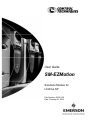
User Guide
SM-EZMotion
Solutions Module for
Unidrive SP
Part Number: 400361-00
Date: February 26, 2004
SM-EZMotion Module
User Guide
Information furnished by Control Techniques Drives Inc. (Control Techniques) is believed to be accurate and reliable. However, no
responsibility is assumed by Control Techniques for its use. Control Techniques reserves the right to change the design or operation
of the equipment described herein and any associated motion products without notice. Control Techniques also assumes no
responsibility for any errors that may appear in this document. Information in this document is subject to change without notice.
P/N 400361-00
Revision: A3
Date: February 26, 2004
© Control Techniques Drives, Inc. 2003, 2004
© Control Techniques Drives, Inc. 2003, 2004 All rights reserved.
Part Number: 400361-00
Revision: A3
Date: Feburary 2004
Information in this document is subject to change without notice, No part if this document may be reproduced or transmitted in any
form or by any means, electronic or mechanical, for any purpose, without the express written permission of Control Techniques.
The following are trademarks of Control Techniques and may not be reproduced in any fashion without written approval of Control
Techniques: EMERSON Motion Control, EMERSON Motion Control PowerTools.
Control Techniques is a Division of EMERSON Co.
Control Techniques is not affiliated with Microsoft Corporation, owner of the MicroSoft, Windows, and Windows NT trademarks.
Microsoft, Windows and Windows NT are registered trademarks of Microsoft Corporation.
MODBUS is a registered trademark of Gould, Inc.
DeviceNet is a registered trademark of the Open DeviceNet Vendor Association.
This document has been prepared to conform to the current released version of the product. Because of our extensive development
efforts and our desire to further improve and enhance the product, inconsistencies may exist between the product and documentation
in some instances. Call your customer support representative if you encounter an inconsistency.
ii
www.controltechniques.com
SM-EZMotion Module User Guide
Document Conventions
Manual conventions have been established to help you learn to use this manual quickly and easily. As much as possible, these
conventions correspond to those found in other Microsoft® Windows® compatible software documentation.
Menu names and options are printed in bold type: the File menu.
Dialog box names begin with uppercase letters: the Axis Limits dialog box.
Dialog box field names are in quotes: “Field Name.”
Button names are in italic: OK button.
Source code is printed in Courier font: Case ERMS.
In addition, you will find the following typographic conventions throughout this manual.
This
Represents
bold
Characters that you must type exactly as they appear. For example, if you are directed to type
a:setup, you should type all the bold characters exactly as they are printed.
italic
Placeholders for information you must provide. For example, if you are directed to type
filename, you should type the actual name for a file instead of the word shown in italic type.
ALL CAPITALS
Directory names, file names, key names, and acronyms.
SMALL CAPS
Non-printable ASCII control characters.
KEY1+KEY2
example: (Alt+F)
A plus sign (+) between key names means to press and hold down the first key while you press
the second key.
KEY1,KEY2
example: (Alt,F)
A comma (,) between key names means to press and release the keys one after the other.
“Warning” indicates a potentially hazardous situation that, if not avoided, could result in death or serious injury.
“Caution” indicates a potentially hazardous situation that, if not avoided, may result in minor or moderate injury.
“Caution” used without the safety alert symbol indicates a potentially hazardous situation that, if not avoided, may result
in property damage.
Note
For the purpose of this manual and product, “Note” indicates essential information about the product or the respective part
of the manual.
Throughout this manual, the word “drive” or "SP" refers to a Unidrive SP.
SM-EZMotion Module User Guide
www.controltechniques.com
iii
Safety Instructions
General Warning
Failure to follow safe installation guidelines can cause death or serious injury. The voltages used in the product can cause
severe electric shock and/or burns and could be lethal. Extreme care is necessary at all times when working with or adjacent
to the product. The installation must comply with all relevant safety legislation in the country of use.
Qualified Person
For the purpose of this manual and product, a “qualified person” is one who is familiar with the installation, construction and
operation of the equipment and the hazards involved. In addition, this individual has the following qualifications:
•
Is trained and authorized to energize, de-energize, clear and ground and tag circuits and equipment in accordance with
established safety practices.
•
Is trained in the proper care and use of protective equipment in accordance with established safety practices.
•
Is trained in rendering first aid.
Reference Materials
The following related manuals and user guides may be useful with your particular system.
iv
•
Unidrive SP User Guide
•
Unidrive SP Advanced User Guide
•
SM-I/O Plus User Guide
•
SM-DeviceNet User Guide
•
SM-Profibus DP User Guide
•
SM-INTERBUS User Guide
•
SM-CANOpen User Guide
•
SM-Resolver User Guide
•
SM-Universal Encoder User Guide
www.controltechniques.com
SM-EZMotion Module User Guide
Safety
Considerations
Safety Information
The SM-EZMotion module and its associated drive are
intended as components for professional incorporation into
complete equipment or systems. If installed incorrectly the
drive may present a safety hazard. The drive uses high
voltages and currents, carries a high level of stored
electrical energy and is used to control mechanical
equipment that can cause injury.
Close attention is required to the electrical installation,
commissioning and maintenance must be carried out by
personnel who have the necessary training and
experience, They must read this safety information and
User Guide carefully.
Careful consideration must be given to the functions of the
drive and solutions module, which might result in a hazard,
either through their intended functions e.g. auto-start or
through incorrect operation due to a fault or trip e.g. stop/
start, forward/reverse, maximum speed, loss of
communications link.
In any application where a malfunction of the drive or
solutions module could lead to damage, loss or injury, a
risk analysis must be carried out and where necessary
further measures taken to reduce the risk. To ensure
mechanical safety additional safety devices such as
electro-mechanical interlocks may be required. The drive
must not be used in a safety critical application without
high-integrity protection against hazards arising from a
malfunction.
General Information
The manufacturer accepts no liability for any
consequences resulting from inappropriate, negligent of
incorrect installation or adjustment of the optional
operation parameters of the equipment or from
mismatching the variable speed drive (drive) with the
motor.
The contents of this guide are believed to be correct at the
time of printing. In the interests of a commitment to a policy
of continuous development and improvement, the
manufacturer reserves the right to change the specification
of the product or its performance, of the contents of this
guide, without notice.
All rights reserved. No parts of this guide may be
reproduced or transmitted in any form of by any means,
electrical or mechanical including photocopying, recording
or by an information storage or retrieval system, without
permission in writing from the publisher.
Drive software version
This product is supplied with the latest version of
Safety Considerations
user-interface and machine control software. If this product
is to be used on a new or existing system with other drives,
there may be some differences between their software and
the software in this product. These differences may cause
this product to function differently. This may also apply to
drives returned from a Control Techniques Service Centre.
If there is any doubt, contact a Control Techniques Drive
Centre.
Safety of Machinery
Within the European Union all machinery in which this
product is used must comply with Directive 89/392/EEC,
Safety of Machinery.
The product has been designed and tested to a high
standard, and failures are very unlikely. However the level
of integrity offered by the product’s control function – for
example stop/start, forward/reverse and maximum speed –
is not sufficient for use in safety-critical applications without
additional independent channels of protection. All
applications where malfunction could cause injury or loss
of life must be subject to a risk assessment, and further
protection provided where needed.
General warning
Failure to follow safe installation guidelines can cause
death or serious injury. The voltages used in this unit can
cause severe electric shock and/or burns, and could be
lethal. Extreme care is necessary at all times when
working with or adjacent to this equipment. The
installation must comply with all relevant safety
legislation in the country of use.
AC supply isolation device
The AC supply must be removed from the drive using an
approved isolation device or disconnect before any
servicing work is performed, other than adjustments to
the settings or parameters specified in the manual. The
drive contains capacitors which remain charged to a
potentially lethal voltage after the supply has been
removed. Allow at least 6 minutes for the Epsilon 205, 3
minutes for Epsilon 202/203 and 30 seconds for E Series
drives after removing the supply before carrying out any
work which may involve contact with electrical
connections to the drive.
Products connected by plug and socket
A special hazard may exist where the drive is
incorporated into a product which is connected to the AC
supply by a plug and socket. When unplugged, the pins of
the plug may be connected to the drive input, which is
only separated from the charge stored in the bus capacitor
by semiconductor devices. To avoid any possibility of
electric shock from the pins, if they are accessible, a
means must be provided for automatically disconnecting
the plug from the drive (e.g., a latching contactor).
Grounding (Earthing, equipotential bonding)
The drive must be grounded by a conductor sufficient to
carry all possible fault current in the event of a fault. The
ground connections shown in the manual must be
followed.
Fuses
Fuses protection must be provided at the input in
www.controltechniques.com
v
accordance with the instructions in the manual.
Isolation of control circuits
The installer must ensure that the external control circuits
are isolated from human contact by at least one layer of
insulation rated for use at the applied AC supply voltage.
vi
www.controltechniques.com
SM-EZMotion Module User Guide
SM-EZMotion Module Technical Manual
Table of Contents
Document Conventions . . . . . . . . . . . . . . . . . . . . . . . . . . . . . . . . . . . . . . . . . . . . . . . . . . . . . . . . . . . . . . . . . . . . . . . . . iii
Safety Instructions. . . . . . . . . . . . . . . . . . . . . . . . . . . . . . . . . . . . . . . . . . . . . . . . . . . . . . . . . . . . . . . . . . . . . . . . .iv
General Warning . . . . . . . . . . . . . . . . . . . . . . . . . . . . . . . . . . . . . . . . . . . . . . . . . . . . . . . . . . . . . . . . . . . . . . . . . . . iv
Qualified Person . . . . . . . . . . . . . . . . . . . . . . . . . . . . . . . . . . . . . . . . . . . . . . . . . . . . . . . . . . . . . . . . . . . . . . . . . . . iv
• Reference Materials. . . . . . . . . . . . . . . . . . . . . . . . . . . . . . . . . . . . . . . . . . . . . . . . . . . . . . . . . . . . . . . . . . . . . . .iv
Safety Considerations
v
1 Introduction
1
1.1 Introduction. . . . . . . . . . . . . . . . . . . . . . . . . . . . . . . . . . . . . . . . . . . . . . . . . . . . . . . . . . . . . . . . . . . . . . . . . . . ..1
1.2 SM-EZMotion Module for Unidrive SP. . . . . . . . . . . . . . . . . . . . . . . . . . . . . . . . . . . . . . . . . . . . . . . . . . . . . . . ..1
1.3 Development Software. . . . . . . . . . . . . . . . . . . . . . . . . . . . . . . . . . . . . . . . . . . . . . . . . . . . . . . . . . . . . . . . . . ..1
1.3.1 Features . . . . . . . . . . . . . . . . . . . . . . . . . . . . . . . . . . . . . . . . . . . . . . . . . . . . . . . . . . . . . . . . . . . . . . . . . 1
2 Installation
2.1
2.2
2.3
2.4
2.5
2.6
3
Mechanical Installation. . . . . . . . . . . . . . . . . . . . . . . . . . . . . . . . . . . . . . . . . . . . . . . . . . . . . . . . . . . . . . . . . . ..3
Slot Selection. . .. . . . . . . . . . . . . . . . . . . . . . . . . . . . . . . . . . . . . . . . . . . . . . . . . . . . . . . . . . . . . . . . . . . . . . . ..3
Electrical Connections. . . . . . . . . . . . . . . . . . . . . . . . . . . . . . . . . . . . . . . . . . . . . . . . . . . . . . . . . . . . . . . . . . . ..3
Digital I/O Connections. . . . . . . . . . . . . . . . . . . . . . . . . . . . . . . . . . . . . . . . . . . . . . . . . . . . . . . . . . . . . . . . . . ..3
Connecting Motor Encoder Feedback to the Unidrive SP. . . . . . . . . . . . . . . . . . . . . . . . . . . . . . . . . . . . . . . . ..3
Simple Servo Motor Phasing Test. . . . . . . . . . . . . . . . . . . . . . . . . . . . . . . . . . . . . . . . . . . . . . . . . . . . . . . . . . ..5
3 PowerTools Pro Configuration Software
7
3.1 Introduction. . . . . . . . . . . . . . . . . . . . . . . . . . . . . . . . . . . . . . . . . . . . . . . . . . . . . . . . . . . . . . . . . . . . . . . . . . . ..7
3.2 Installing PowerTools Pro. . . . . . . . . . . . . . . . . . . . . . . . . . . . . . . . . . . . . . . . . . . . . . . . . . . . . . . . . . . . . . . . ..7
3.2.1 From the Power CD. . . . . . . . . . . . . . . . . . . . . . . . . . . . . . . . . . . . . . . . . . . . . . . . . . . . . . . . . . . . . . . . . 7
3.2.2 From the Web . . . . . . . . . . . . . . . . . . . . . . . . . . . . . . . . . . . . . . . . . . . . . . . . . . . . . . . . . . . . . . . . . . . . . 7
3.3 How PowerTools Pro is Organized. . . . . . . . . . . . . . . . . . . . . . . . . . . . . . . . . . . . . . . . . . . . . . . . . . . . . . . . . ..7
3.3.1 Menu Bar. . . . . . . . . . . . . . . . . . . . . . . . . . . . . . . . . . . . . . . . . . . . . . . . . . . . . . . . . . . . . . . . . . . . . . . . . 7
3.3.2 Tool Bar. . . . . . . . . . . . . . . . . . . . . . . . . . . . . . . . . . . . . . . . . . . . . . . . . . . . . . . . . . . . . . . . . . . . . . . . . 13
3.3.3 Hierarchy . . . . . . . . . . . . . . . . . . . . . . . . . . . . . . . . . . . . . . . . . . . . . . . . . . . . . . . . . . . . . . . . . . . . . . . . 15
3.3.4 View. . . . . . . . . . . . . . . . . . . . . . . . . . . . . . . . . . . . . . . . . . . . . . . . . . . . . . . . . . . . . . . . . . . . . . . . . . . . 16
3.3.5 View Tabs . . . . . . . . . . . . . . . . . . . . . . . . . . . . . . . . . . . . . . . . . . . . . . . . . . . . . . . . . . . . . . . . . . . . . . . 16
3.3.6 Status Bar . . . . . . . . . . . . . . . . . . . . . . . . . . . . . . . . . . . . . . . . . . . . . . . . . . . . . . . . . . . . . . . . . . . . . . . 16
4 Communications
4.1
4.2
4.3
4.4
17
Communications Protocol. . . . . . . . . . . . . . . . . . . . . . . . . . . . . . . . . . . . . . . . . . . . . . . . . . . . . . . . . . . . . . . ..17
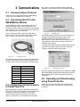
Connecting the PC to the SM-EZMotion Module. . .. . . . . . . . . . . . . . . . . . . . . . . . . . . . . . . . . . . . . . . . . . . ..17
Configuring Communications in PowerTools Pro. . . . . . . . . . . . . . . . . . . . . . . . . . . . . . . . . . . . . . . . . . . . . ..17
Uploading and Downloading using PowerTools Pro. . . . . . . . . . . . . . . . . . . . . . . . . . . . . . . . . . . . . . . . . . . ..17
4.4.1 Uploading . . . . . . . . . . . . . . . . . . . . . . . . . . . . . . . . . . . . . . . . . . . . . . . . . . . . . . . . . . . . . . . . . . . . . . . 18
4.4.2 Downloading . . . . . . . . . . . . . . . . . . . . . . . . . . . . . . . . . . . . . . . . . . . . . . . . . . . . . . . . . . . . . . . . . . . . . 18
4.4.3 Non-Volatile Memory (NVM) Options for Uploading and Downloading. . . . . . . . . . . . . . . . . . . . . . . . . 18
4.4.4 Updating to RAM . . . . . . . . . . . . . . . . . . . . . . . . . . . . . . . . . . . . . . . . . . . . . . . . . . . . . . . . . . . . . . . . . . 19
4.4.5 PowerTools Pro Operation Preferences . . . . . . . . . . . . . . . . . . . . . . . . . . . . . . . . . . . . . . . . . . . . . . . . 19
4.4.6 Secure Downloading . . . . . . . . . . . . . . . . . . . . . . . . . . . . . . . . . . . . . . . . . . . . . . . . . . . . . . . . . . . . . . . 20
5 How Motion Works
23
5.1 Introduction. . . . . . . . . . . . . . . . . . . . . . . . . . . . . . . . . . . . . . . . . . . . . . . . . . . . . . . . . . . . . . . . . . . . . . . . . . ..23
SM-EZMotion Module User Guide
www.controltechniques.com
vii
SM-EZMotion Module Technical Manual
5.2 Jog. . . . . . . . . . . . . . . . . . . . . . . . . . . . . . . . . . . . . . . . . . . . . . . . . . . . . . . . . . . . . . . . . . . . . . . . . . . . . . . . . .23
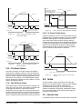
5.3 Home. . . . . . . . . . . . . . . . . . . . . . . . . . . . . . . . . . . . . . . . . . . . . . . . . . . . . . . . . . . . . . . . . . . . . . . . . . . . . . . .23
5.3.1 Home to Marker . . . . . . . . . . . . . . . . . . . . . . . . . . . . . . . . . . . . . . . . . . . . . . . . . . . . . . . . . . . . . . . . . . 23
5.3.2 Home to Sensor . . . . . . . . . . . . . . . . . . . . . . . . . . . . . . . . . . . . . . . . . . . . . . . . . . . . . . . . . . . . . . . . . . 24
5.3.3 Home to Sensor then Marker . . . . . . . . . . . . . . . . . . . . . . . . . . . . . . . . . . . . . . . . . . . . . . . . . . . . . . . . 24
5.3.4 If On Sensor Options . . . . . . . . . . . . . . . . . . . . . . . . . . . . . . . . . . . . . . . . . . . . . . . . . . . . . . . . . . . . . . 25
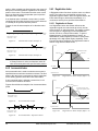
5.4 Index. . . . . . . . . . . . . . . . . . . . . . . . . . . . . . . . . . . . . . . . . . . . . . . . . . . . . . . . . . . . . . . . . . . . . . . . . . . . . . . . .25
5.4.1 Absolute Index . . . . . . . . . . . . . . . . . . . . . . . . . . . . . . . . . . . . . . . . . . . . . . . . . . . . . . . . . . . . . . . . . . . 25
5.4.2 Incremental Index . . . . . . . . . . . . . . . . . . . . . . . . . . . . . . . . . . . . . . . . . . . . . . . . . . . . . . . . . . . . . . . . . 26
5.4.3 Registration Index. . . . . . . . . . . . . . . . . . . . . . . . . . . . . . . . . . . . . . . . . . . . . . . . . . . . . . . . . . . . . . . . . 26
5.4.4 Rotary Plus Index . . . . . . . . . . . . . . . . . . . . . . . . . . . . . . . . . . . . . . . . . . . . . . . . . . . . . . . . . . . . . . . . . 27
5.4.5 Rotary Minus Index. . . . . . . . . . . . . . . . . . . . . . . . . . . . . . . . . . . . . . . . . . . . . . . . . . . . . . . . . . . . . . . . 27
5.4.6 Timed Index . . . . . . . . . . . . . . . . . . . . . . . . . . . . . . . . . . . . . . . . . . . . . . . . . . . . . . . . . . . . . . . . . . . . . 27
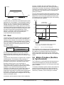
5.5 Gear. . . . . . . . . . . . . . . . . . . . . . . . . . . . . . . . . . . . . . . . . . . . . . . . . . . . . . . . . . . . . . . . . . . . . . . . . . . . . . . . .28
5.6 Motion Timebase (Realtime vs. Synchronized). . .. . . . . . . . . . . . . . . . . . . . . . . . . . . . . . . . . . . . . . . . . . . . . .28
5.7 Summing Multiple Profiles. . . . . . . . . . . . . . . . . . . . . . . . . . . . . . . . . . . . . . . . . . . . . . . . . . . . . . . . . . . . . . . .29
6 How I/O Works
6.1
6.2
6.3
6.4
31
I/O Scan. . . . . . . . . . . . . . . . . . . . . . . . . . . . . . . . . . . . . . . . . . . . . . . . . . . . . . . . . . . . . . . . . . . . . . . . . . . . . .31
SM-EZMotion Module I/O. . . . . . . . . . . . . . . . . . . . . . . . . . . . . . . . . . . . . . . . . . . . . . . . . . . . . . . . . . . . . . . . .31
Unidrive SP I/O. . . . . . . . . . . . . . . . . . . . . . . . . . . . . . . . . . . . . . . . . . . . . . . . . . . . . . . . . . . . . . . . . . . . . . . . .31
SM-I/O Plus Module I/O. . . . . . . . . . . . . . . . . . . . . . . . . . . . . . . . . . . . . . . . . . . . . . . . . . . . . . . . . . . . . . . . . .31
7 Configuring an Application
33
7.1 Introduction. . . . . . . . . . . . . . . . . . . . . . . . . . . . . . . . . . . . . . . . . . . . . . . . . . . . . . . . . . . . . . . . . . . . . . . . . . . .33
7.2 Define Hardware. . . . . . . . . . . . . . . . . . . . . . . . . . . . . . . . . . . . . . . . . . . . . . . . . . . . . . . . . . . . . . . . . . . . . . . .33
7.2.1 Drive/Encoder View . . . . . . . . . . . . . . . . . . . . . . . . . . . . . . . . . . . . . . . . . . . . . . . . . . . . . . . . . . . . . . . 33
7.2.2 Slot # View . . . . . . . . . . . . . . . . . . . . . . . . . . . . . . . . . . . . . . . . . . . . . . . . . . . . . . . . . . . . . . . . . . . . . . 40
7.2.3 Unidrive SP Parameters View . . . . . . . . . . . . . . . . . . . . . . . . . . . . . . . . . . . . . . . . . . . . . . . . . . . . . . . 47
7.2.4 SP Menu Initialization View . . . . . . . . . . . . . . . . . . . . . . . . . . . . . . . . . . . . . . . . . . . . . . . . . . . . . . . . . 47
7.3 Configure Setup Parameters. . . . . . . . . . . . . . . . . . . . . . . . . . . . . . . . . . . . . . . . . . . . . . . . . . . . . . . . . . . . . .48
7.3.1 Setup View . . . . . . . . . . . . . . . . . . . . . . . . . . . . . . . . . . . . . . . . . . . . . . . . . . . . . . . . . . . . . . . . . . . . . . 48
7.3.2 User Units View . . . . . . . . . . . . . . . . . . . . . . . . . . . . . . . . . . . . . . . . . . . . . . . . . . . . . . . . . . . . . . . . . . 49
7.3.3 Master Units Setup View . . . . . . . . . . . . . . . . . . . . . . . . . . . . . . . . . . . . . . . . . . . . . . . . . . . . . . . . . . . 50
7.3.4 Position View . . . . . . . . . . . . . . . . . . . . . . . . . . . . . . . . . . . . . . . . . . . . . . . . . . . . . . . . . . . . . . . . . . . . 52
7.3.5 Velocity View . . . . . . . . . . . . . . . . . . . . . . . . . . . . . . . . . . . . . . . . . . . . . . . . . . . . . . . . . . . . . . . . . . . . 53
7.3.6 Ramps View . . . . . . . . . . . . . . . . . . . . . . . . . . . . . . . . . . . . . . . . . . . . . . . . . . . . . . . . . . . . . . . . . . . . . 53
7.3.7 Current View. . . . . . . . . . . . . . . . . . . . . . . . . . . . . . . . . . . . . . . . . . . . . . . . . . . . . . . . . . . . . . . . . . . . . 54
7.3.8 Tuning View . . . . . . . . . . . . . . . . . . . . . . . . . . . . . . . . . . . . . . . . . . . . . . . . . . . . . . . . . . . . . . . . . . . . . 54
7.3.9 Errors View . . . . . . . . . . . . . . . . . . . . . . . . . . . . . . . . . . . . . . . . . . . . . . . . . . . . . . . . . . . . . . . . . . . . . . 56
7.3.10 PLS View . . . . . . . . . . . . . . . . . . . . . . . . . . . . . . . . . . . . . . . . . . . . . . . . . . . . . . . . . . . . . . . . . . . . . . 58
7.3.11 Setup NVM View . . . . . . . . . . . . . . . . . . . . . . . . . . . . . . . . . . . . . . . . . . . . . . . . . . . . . . . . . . . . . . . . 59
7.3.12 Capture View . . . . . . . . . . . . . . . . . . . . . . . . . . . . . . . . . . . . . . . . . . . . . . . . . . . . . . . . . . . . . . . . . . . 59
7.3.13 Queues View . . . . . . . . . . . . . . . . . . . . . . . . . . . . . . . . . . . . . . . . . . . . . . . . . . . . . . . . . . . . . . . . . . . 60
7.3.14 User Variables View . . . . . . . . . . . . . . . . . . . . . . . . . . . . . . . . . . . . . . . . . . . . . . . . . . . . . . . . . . . . . . 62
7.3.15 User Bits View . . . . . . . . . . . . . . . . . . . . . . . . . . . . . . . . . . . . . . . . . . . . . . . . . . . . . . . . . . . . . . . . . . 63
7.4 Configure I/O. . .. . . . . . . . . . . . . . . . . . . . . . . . . . . . . . . . . . . . . . . . . . . . . . . . . . . . . . . . . . . . . . . . . . . . . . . .64
7.4.1 Assignments View . . . . . . . . . . . . . . . . . . . . . . . . . . . . . . . . . . . . . . . . . . . . . . . . . . . . . . . . . . . . . . . . 64
7.4.2 EZ Motion I/O Setup View . . . . . . . . . . . . . . . . . . . . . . . . . . . . . . . . . . . . . . . . . . . . . . . . . . . . . . . . . . 66
7.4.3 Selector View . . . . . . . . . . . . . . . . . . . . . . . . . . . . . . . . . . . . . . . . . . . . . . . . . . . . . . . . . . . . . . . . . . . . 66
7.4.4 Analog Inputs View. . . . . . . . . . . . . . . . . . . . . . . . . . . . . . . . . . . . . . . . . . . . . . . . . . . . . . . . . . . . . . . . 68
7.4.5 Analog Outputs. . . . . . . . . . . . . . . . . . . . . . . . . . . . . . . . . . . . . . . . . . . . . . . . . . . . . . . . . . . . . . . . . . . 69
7.5 Define Motion Profiles. . . . . . . . . . . . . . . . . . . . . . . . . . . . . . . . . . . . . . . . . . . . . . . . . . . . . . . . . . . . . . . . . . . .71
7.5.1 Jog View . . . . . . . . . . . . . . . . . . . . . . . . . . . . . . . . . . . . . . . . . . . . . . . . . . . . . . . . . . . . . . . . . . . . . . . . 72
viii
www.controltechniques.com
SM-EZMotion Module User Guide
7.5.2 Home View . . . . . . . . . . . . . . . . . . . . . . . . . . . . . . . . . . . . . . . . . . . . . . . . . . . . . . . . . . . . . . . . . . . . . . 73
7.5.3 Index View. . . . . . . . . . . . . . . . . . . . . . . . . . . . . . . . . . . . . . . . . . . . . . . . . . . . . . . . . . . . . . . . . . . . . . . 75
7.5.4 Gearing View. . . . . . . . . . . . . . . . . . . . . . . . . . . . . . . . . . . . . . . . . . . . . . . . . . . . . . . . . . . . . . . . . . . . . 80
7.6 Create User Programs. . .. . . . . . . . . . . . . . . . . . . . . . . . . . . . . . . . . . . . . . . . . . . . . . . . . . . . . . . . . . . . . . . ..80
7.6.1 Program View . . . . . . . . . . . . . . . . . . . . . . . . . . . . . . . . . . . . . . . . . . . . . . . . . . . . . . . . . . . . . . . . . . . . 80
8 How User Programs Work
81
8.1 Program Window Components. . . . . . . . . . . . . . . . . . . . . . . . . . . . . . . . . . . . . . . . . . . . . . . . . . . . . . . . . . . ..81
8.2 Program Parameters. . . . . . . . . . . . . . . . . . . . . . . . . . . . . . . . . . . . . . . . . . . . . . . . . . . . . . . . . . . . . . . . . . . ..81
8.2.1 Program Name . . . . . . . . . . . . . . . . . . . . . . . . . . . . . . . . . . . . . . . . . . . . . . . . . . . . . . . . . . . . . . . . . . . 81
8.2.2 Program Number. . . . . . . . . . . . . . . . . . . . . . . . . . . . . . . . . . . . . . . . . . . . . . . . . . . . . . . . . . . . . . . . . . 81
8.2.3 Task Number. . . . . . . . . . . . . . . . . . . . . . . . . . . . . . . . . . . . . . . . . . . . . . . . . . . . . . . . . . . . . . . . . . . . . 81
8.2.4 Run Anytime Enable . . . . . . . . . . . . . . . . . . . . . . . . . . . . . . . . . . . . . . . . . . . . . . . . . . . . . . . . . . . . . . . 82
8.3 Program Toolbar. . . . . . . . . . . . . . . . . . . . . . . . . . . . . . . . . . . . . . . . . . . . . . . . . . . . . . . . . . . . . . . . . . . . . . ..82
8.3.1 Undo . . . . . . . . . . . . . . . . . . . . . . . . . . . . . . . . . . . . . . . . . . . . . . . . . . . . . . . . . . . . . . . . . . . . . . . . . . . 82
8.3.2 Redo . . . . . . . . . . . . . . . . . . . . . . . . . . . . . . . . . . . . . . . . . . . . . . . . . . . . . . . . . . . . . . . . . . . . . . . . . . . 82
8.3.3 Find . . . . . . . . . . . . . . . . . . . . . . . . . . . . . . . . . . . . . . . . . . . . . . . . . . . . . . . . . . . . . . . . . . . . . . . . . . . . 82
8.3.4 Find Next . . . . . . . . . . . . . . . . . . . . . . . . . . . . . . . . . . . . . . . . . . . . . . . . . . . . . . . . . . . . . . . . . . . . . . . . 82
8.3.5 Bookmark . . . . . . . . . . . . . . . . . . . . . . . . . . . . . . . . . . . . . . . . . . . . . . . . . . . . . . . . . . . . . . . . . . . . . . . 82
8.3.6 Goto Next Bookmark . . . . . . . . . . . . . . . . . . . . . . . . . . . . . . . . . . . . . . . . . . . . . . . . . . . . . . . . . . . . . . . 82
8.3.7 Goto Previous Bookmark . . . . . . . . . . . . . . . . . . . . . . . . . . . . . . . . . . . . . . . . . . . . . . . . . . . . . . . . . . . 82
8.3.8 Clear All Bookmarks . . . . . . . . . . . . . . . . . . . . . . . . . . . . . . . . . . . . . . . . . . . . . . . . . . . . . . . . . . . . . . . 83
8.3.9 Red Dot Help. . . . . . . . . . . . . . . . . . . . . . . . . . . . . . . . . . . . . . . . . . . . . . . . . . . . . . . . . . . . . . . . . . . . . 83
8.3.10 Drag In Operands . . . . . . . . . . . . . . . . . . . . . . . . . . . . . . . . . . . . . . . . . . . . . . . . . . . . . . . . . . . . . . . . 83
8.3.11 Drag In Variables. . . . . . . . . . . . . . . . . . . . . . . . . . . . . . . . . . . . . . . . . . . . . . . . . . . . . . . . . . . . . . . . . 83
8.3.12 Lock Program . . . . . . . . . . . . . . . . . . . . . . . . . . . . . . . . . . . . . . . . . . . . . . . . . . . . . . . . . . . . . . . . . . . 83
8.3.13 Run Program . . . . . . . . . . . . . . . . . . . . . . . . . . . . . . . . . . . . . . . . . . . . . . . . . . . . . . . . . . . . . . . . . . . . 83
8.3.14 Program Where Am I?. . . . . . . . . . . . . . . . . . . . . . . . . . . . . . . . . . . . . . . . . . . . . . . . . . . . . . . . . . . . . 83
8.3.15 Stop . . . . . . . . . . . . . . . . . . . . . . . . . . . . . . . . . . . . . . . . . . . . . . . . . . . . . . . . . . . . . . . . . . . . . . . . . . . 83
8.3.16 Disable/Enable Error Check . . . . . . . . . . . . . . . . . . . . . . . . . . . . . . . . . . . . . . . . . . . . . . . . . . . . . . . . 83
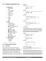
8.4 Program Instruction List. . .. . . . . . . . . . . . . . . . . . . . . . . . . . . . . . . . . . . . . . . . . . . . . . . . . . . . . . . . . . . . . . ..84
8.4.1 Program Flow Instructions. . . . . . . . . . . . . . . . . . . . . . . . . . . . . . . . . . . . . . . . . . . . . . . . . . . . . . . . . . . 84
8.4.2 Motion Instructions . . . . . . . . . . . . . . . . . . . . . . . . . . . . . . . . . . . . . . . . . . . . . . . . . . . . . . . . . . . . . . . . 87
8.4.3 Motion Modifier Instructions . . . . . . . . . . . . . . . . . . . . . . . . . . . . . . . . . . . . . . . . . . . . . . . . . . . . . . . . . 89
8.5 Red Dot Error Bar. . . . . . . . . . . . . . . . . . . . . . . . . . . . . . . . . . . . . . . . . . . . . . . . . . . . . . . . . . . . . . . . . . . . . ..89
8.6 Program Code Window. . . . . . . . . . . . . . . . . . . . . . . . . . . . . . . . . . . . . . . . . . . . . . . . . . . . . . . . . . . . . . . . . ..90
8.7 Program Multi-tasking. . . . . . . . . . . . . . . . . . . . . . . . . . . . . . . . . . . . . . . . . . . . . . . . . . . . . . . . . . . . . . . . . . ..90
9 Starting and Stopping Motion
93
9.1 Starting Motion. . .. . . . . . . . . . . . . . . . . . . . . . . . . . . . . . . . . . . . . . . . . . . . . . . . . . . . . . . . . . . . . . . . . . . . . ..93
9.1.1 From Assignments . . . . . . . . . . . . . . . . . . . . . . . . . . . . . . . . . . . . . . . . . . . . . . . . . . . . . . . . . . . . . . . . 93
9.1.2 From Programs . . . . . . . . . . . . . . . . . . . . . . . . . . . . . . . . . . . . . . . . . . . . . . . . . . . . . . . . . . . . . . . . . . . 94
9.1.3 From PowerTools Pro . . . . . . . . . . . . . . . . . . . . . . . . . . . . . . . . . . . . . . . . . . . . . . . . . . . . . . . . . . . . . . 96
9.2 Stopping Motion. . .. . . . . . . . . . . . . . . . . . . . . . . . . . . . . . . . . . . . . . . . . . . . . . . . . . . . . . . . . . . . . . . . . . . . ..96
9.2.1 From Assignments . . . . . . . . . . . . . . . . . . . . . . . . . . . . . . . . . . . . . . . . . . . . . . . . . . . . . . . . . . . . . . . . 96
9.2.2 From Programs . . . . . . . . . . . . . . . . . . . . . . . . . . . . . . . . . . . . . . . . . . . . . . . . . . . . . . . . . . . . . . . . . . . 96
9.2.3 From PowerTools Pro . . . . . . . . . . . . . . . . . . . . . . . . . . . . . . . . . . . . . . . . . . . . . . . . . . . . . . . . . . . . . . 97
10 Starting and Stopping Programs
99
10.1 Starting Programs. . . . . . . . . . . . . . . . . . . . . . . . . . . . . . . . . . . . . . . . . . . . . . . . . . . . . . . . . . . . . . . . . . . . ..99
10.1.1 From Assignments . . . . . . . . . . . . . . . . . . . . . . . . . . . . . . . . . . . . . . . . . . . . . . . . . . . . . . . . . . . . . . . 99
10.1.2 From Programs . . . . . . . . . . . . . . . . . . . . . . . . . . . . . . . . . . . . . . . . . . . . . . . . . . . . . . . . . . . . . . . . . . 99
10.1.3 From PowerTools Pro . . . . . . . . . . . . . . . . . . . . . . . . . . . . . . . . . . . . . . . . . . . . . . . . . . . . . . . . . . . . . 99
SM-EZMotion Module User Guide
www.controltechniques.com
ix
SM-EZMotion Module Technical Manual
10.2 Stopping Programs. . . . . . . . . . . . . . . . . . . . . . . . . . . . . . . . . . . . . . . . . . . . . . . . . . . . . . . . . . . . . . . . . . . . .99
10.2.1 From Assignments . . . . . . . . . . . . . . . . . . . . . . . . . . . . . . . . . . . . . . . . . . . . . . . . . . . . . . . . . . . . . . . 99
10.2.2 From Programs. . . . . . . . . . . . . . . . . . . . . . . . . . . . . . . . . . . . . . . . . . . . . . . . . . . . . . . . . . . . . . . . . . 99
10.2.3 From PowerTools Pro. . . . . . . . . . . . . . . . . . . . . . . . . . . . . . . . . . . . . . . . . . . . . . . . . . . . . . . . . . . . . 99
11 Parameter Descriptions
101
12 Drive Parameters Used by SM-EZMotion Module
131
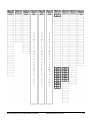
12.1 Description. . . . . . . . . . . . . . . . . . . . . . . . . . . . . . . . . . . . . . . . . . . . . . . . . . . . . . . . . . . . . . . . . . . . . . . . . .131
12.2 Chart. . . . . . . . . . . . . . . . . . . . . . . . . . . . . . . . . . . . . . . . . . . . . . . . . . . . . . . . . . . . . . . . . . . . . . . . . . . . . . .131
12.3 SM-EZMotion Module Setup Parameters. . . . . . . . . . . . . . . . . . . . . . . . . . . . . . . . . . . . . . . . . . . . . . . . . . .134
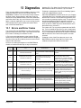
13 Diagnostics
137
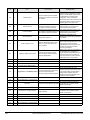
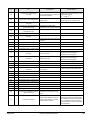
13.1 Errors and Error Codes. . . . . . . . . . . . . . . . . . . . . . . . . . . . . . . . . . . . . . . . . . . . . . . . . . . . . . . . . . . . . . . . .137
13.2 Analog Outputs. . . . . . . . . . . . . . . . . . . . . . . . . . . . . . . . . . . . . . . . . . . . . . . . . . . . . . . . . . . . . . . . . . . . . . .140
13.3 PowerTools Pro. . . . . . . . . . . . . . . . . . . . . . . . . . . . . . . . . . . . . . . . . . . . . . . . . . . . . . . . . . . . . . . . . . . . . .140
13.3.1 Watch Window . . . . . . . . . . . . . . . . . . . . . . . . . . . . . . . . . . . . . . . . . . . . . . . . . . . . . . . . . . . . . . . . . 140
13.3.2 Errors View . . . . . . . . . . . . . . . . . . . . . . . . . . . . . . . . . . . . . . . . . . . . . . . . . . . . . . . . . . . . . . . . . . . . 141
13.3.3 Status Bar. . . . . . . . . . . . . . . . . . . . . . . . . . . . . . . . . . . . . . . . . . . . . . . . . . . . . . . . . . . . . . . . . . . . . 142
13.3.4 Where Am I?. . . . . . . . . . . . . . . . . . . . . . . . . . . . . . . . . . . . . . . . . . . . . . . . . . . . . . . . . . . . . . . . . . . 142
13.3.5 Online View Tabs . . . . . . . . . . . . . . . . . . . . . . . . . . . . . . . . . . . . . . . . . . . . . . . . . . . . . . . . . . . . . . . 142
13.4 Clearing SLX.dF trip after installing SM-EZMotion module. . .. . . . . . . . . . . . . . . . . . . . . . . . . . . . . . . . . . .143
13.5 Clearing the SM-EZMotion module memory. . . . . . . . . . . . . . . . . . . . . . . . . . . . . . . . . . . . . . . . . . . . . . . . .143
14 Creating a Custom Motor File
145
15 Glossary
149
16 Index
153
x
www.controltechniques.com
SM-EZMotion Module User Guide
1 Introduction
1.1 Introduction
Modern variable speed drive such as the Unidrive SP offer
a multitude of built-in features such as ramp control, speed
control, PID Loops, and even simple position control.
However, the base drive’s functionality is too limited for
many applications. When it comes to more complex
applications, the user must resort to using external
equipment such as PLC's to control the drive from a
system point of view.
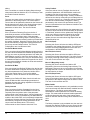
However, the flexibility of the Unidrive SP can be
substantially increased by using an SM-EZMotion module.
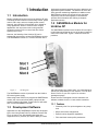
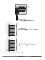
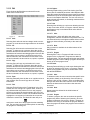
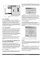
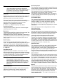
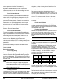
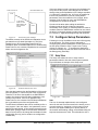
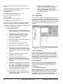
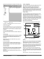
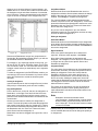
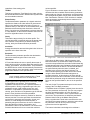
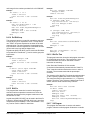
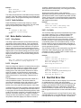
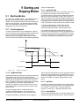
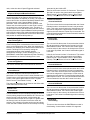
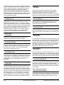
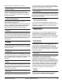
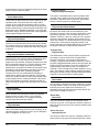
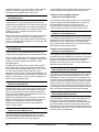
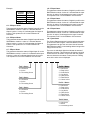
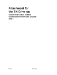
The SM-EZMotion module is 1 1/2 axis controller with a
Figure 1:
Slot Diagram
The SM-EZMotion module is powered from the Unidrive
SP internal power supply.
When using PowerTools Pro to program the SM-EZMotion
module, the user must indicate which options slot the
module is fitted in. By default, PowerTools Pro will select
Slot 3 for the SM-EZMotion module.
dedicated processor that allows the user to write their own
application specific software. The Unidrive SP drive also
offers powerful networking capabilities in addition to the
SM-EZMotion module so that many drives (and other
equipment) can be linked together to communicate
process wide information thus offering a complete
application solution.
1.2 SM-EZMotion Module for
Unidrive SP
The SM-EZMotion module for the Unidrive SP is an option
module that can be fitted to any one of the three expansion
slots in the Unidrive SP. Figure 1 shows the three slot
positions.
edit and maintain your system setup. You can download or
upload your setup data to or from a device. You can also
save it to a file on your PC or print it for review or
permanent storage.
PowerTools Pro is designed to be the easiest-to-use
software available for the 11/2 axis motion controllers.
1.3.1 Features
1.3 Development Software
•
"Hierarchy View" for quick navigation to any setup
view
Applications for the SM-EZMotion module are developed
by the user using PowerTools Pro software. PowerTools
Pro is an easy-to use, Windows® based setup and
diagnostics tool. It provides you with the ability to create,
•
Simple I/O function assignments
•
Powerful online diagnostic capabilities
•
Fill-in-the-blank motion profile parameters
Introduction
www.controltechniques.com
1
•
Programming
PowerTools Pro will run on Windows 98, NT, 2000, and XP
operating systems.
2
www.controltechniques.com
SM-EZMotion Module User Guide
2 Installation
This section of the manual will cover basic installation
information.
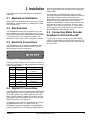
2.1 Mechanical Installation
Please refer to the Installation Sheet that comes with the
SM-EZMotion module for details on installing the module
into the Unidrive SP.
2.2 Slot Selection
The SM-EZMotion module may be placed in any of the
three available option slots on the Unidrive SP. The user
must indicate which slot the SM-EZMotion module is fitted
in using PowerTools Pro configuration software. The
default slot number is Slot 3 in the configuration software.
2.3 Electrical Connections
be found on the Setup view in PowerTools Pro (see “Setup
View” on page 48 for more information on the Trajectory
Update Rate).
The digital I/O on the SM-EZMotion module are also
unique (as compared to Unidrive SP digital I/O and SM-I/O
Plus module I/O) because they can be used in the
SM-EZMotion module high speed capture process. Even
though they are only updated once every Trajectory
Update, the SM-EZMotion module processor knows when
they activate to within 1 microsecond. Therefore, when
Capture is used, they can be accurate to 1 microsecond
(see “Capture View” on page 59 for more information on
the SM-EZMotion module Capture object).
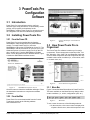
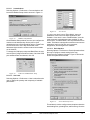
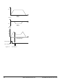
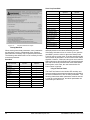
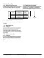
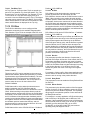
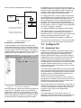
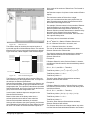
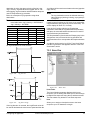
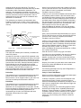
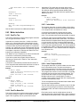
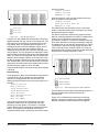
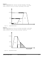
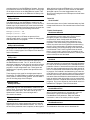
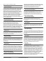
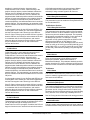
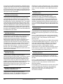
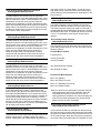
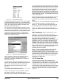
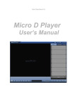
2.5 Connecting Motor Encoder
Feedback to the Unidrive SP
Figure 3 can be used to connect the encoder feedback
signals for various different motors to the Unidrive SP. For
further installation information, please refer to the Unidrive
SP User Guide.
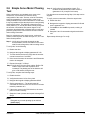
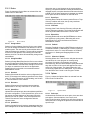
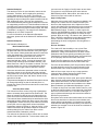
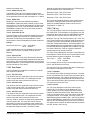
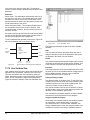
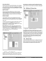
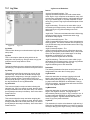
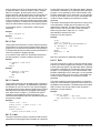
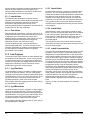
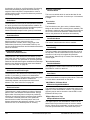
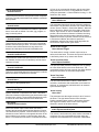
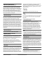
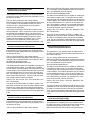
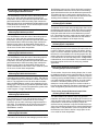
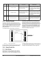
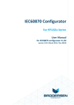
The SM-EZMotion module has three separate terminal
blocks used to access the different features. Figure 2
shows a diagram of these connections.
1 2 3 4
Figure 2:
5 6
7
Connection Diagram
The terminals are numbered from Terminal 1 on the left to
Terminal 7 on the right. The different terminal functions are
listed in the table below.
Terminal #
Function
Description
1
OV Common
OV Common connection for
digital I/O
2
Input1
Digital Input 1
3
Input2
Digital Input 2
4
Input3
Digital Input 3
5
Input4
Digital Input 4
6
Output1
Digital Output 1
7
Output 2
Digital Output 2
2.4 Digital I/O Connections
The SM-EZMotion module is equipped with 4 digital inputs
and 2 digital outputs. The I/O are electrically sourcing I/O.
All I/O utilize positive logic meaning that they are active
when a positive voltage is applied (10-30 VDC). See the
Specifications section at the back of the manual for more
detailed information on the digital I/O.
The digital I/O can be used to control different functions in
the SM-EZMotion module. The digital I/O on the
SM-EZMotion module are updated at the SM-EZMotion
Trajectory Update Rate. The Trajectory Update Rate can
Installation
www.controltechniques.com
3
I/O Connector 1
I/O Connector 2
I/O Connector 4
L1
L2
L3
U
V
W
Encoder Feedback
15 pin D-sub or SM-ETC
1
2
GREEN
CHANNEL A/
CHANNEL B
3
BLUE
4
5
ORANGE
6
7
8
YELLOW
9
10
WHT/BRN
11
12
RED/ORG
13
14
RED/BLU
0V COMMON
MOTOR THERM
15
CHANNEL A
CHANNEL B/
CHANNEL Z
CHANNEL Z/
CHANNEL U
CHANNEL U/
CHANNEL V
CHANNEL V/
CHANNEL W
CHANNEL W/
+5 VDC
BROWN
BLACK
WHT/GRY
NT, MG, or MH Motor
GRY/WHT
BRN/WHT
ORG/RED
Encoder Feedback
15 pin D-sub or SM-ETC
1
2
GRY/PNK
3
4
5
RED
BRN/GRN
CHANNEL U
6
7
CHANNEL U/
8
YELLOW
CHANNEL A
CHANNEL A/
CHANNEL B
CHANNEL B/
CHANNEL Z
CHANNEL Z/
CHANNEL V
CHANNEL V/
CHANNEL W
CHANNEL W/
+5 VDC
Figure 3:
4
RED/BLU
BLUE
WHT/GRN
SIBAA-xxx Cable
GREEN
9
10
11
GREY
12
13
PURPLE
14
15
BLUE
EZ or UM Motor
PINK
BLACK
RED
BROWN
Motor Feedback to Unidrive SP Connection Diagram
www.emersonct.com
SM-EZMotion Module User Guide
2.6 Simple Servo Motor Phasing
Test
Step 3: Verify wiring of commutation signals. The
Unidrive SP Advanced User Guide section 3
(parameter 3.25) is helpful for this step.
When connecting a non-standard servo motor to the
Unidrive SP, it is necessary to know the wiring
configuration of the motor. At times, all of the necessary
wiring documentation for connecting the motor is not
readily available from the motor manufacturer. In that case,
it may be possible to follow the simple servo motor phasing
test described below. This will help to determine if the
motor phases (U, V, and W) are wired correctly along with
the encoder commutation and channel signals. If the
procedure described below is followed, and you still have
problems, please refer to the Unidrive SP User Guide for
further wiring information.
If no trips were encountered during Step 2, this step can be
skipped.
Begin by entering the motor peak current, continuous
current, number of poles, encoder lines per rev., etc. Then
follow the steps below.
To verify correct commutation, follow the steps below:
A Enable the drive
B Navigate the keypad to display parameter #0.40 and
set the parameter to 1
C If an tunE3 or other tunEx trip results, rewiring is
needed
D Swap the U and V commutation signals at the drive
end
Repeat steps A through C to verify.
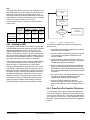
Step 1: Verify wiring of encoder channels per the
documentation. Define CW rotation of the motor
shaft, from the flange side, with increasing counts.
To verify this, do the following
A Disable the drive
B Navigate the keypad to display parameter # 3.29
C Turn the shaft clockwise and verify that the encoder
counts increase from 0 to 65535
D If the counts decrease, the encoder A and B channels
need to be swapped
E Repeat A through C of Step 1
Step 2: Verify wiring of motor power cables. Define CW
rotation of the motor with a positive drive
command. The phasing test of the Unidrive will
give a CW rotation during the test.
To verify this, complete the following steps:
A Enable the drive
B Verify that the motor is free of any load
C Navigate the keypad to display parameter #0.40
D Set the parameter to 1. The phasing test will
command the motor to move one rev CW. It will also
reset the parameter to 0
E If the motor moves in the CCW direction, the motor
power is wired incorrectly
F Swap the U and V phases and repeat A through D of
Step 2
Note
Disregard any encoder phasing trip at this time
[tunEx trips]
Installation
www.controltechniques.com
5
6
www.emersonct.com
SM-EZMotion Module User Guide
3 PowerTools Pro
Configuration
Software
3.1 Introduction
PowerTools Pro is the software used to configure
hardware type, setup parameters, I/O functionality, motion
profiles, user programs, and networks for the
SM-EZMotion module. PowerTools Pro can also be used
as a diagnostic tool and for troubleshooting assistance.
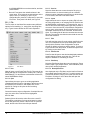
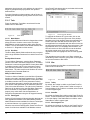
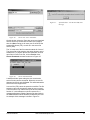
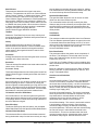
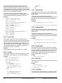
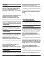
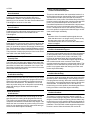
3.2 Installing PowerTools Pro
3.2.1 From the Power CD
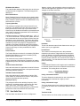
Figure 5:
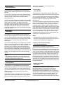
PowerTools Pro can be installed directly from the
SM-EZMotion CD that ships with every SM-EZMotion
module. To install PowerTools Pro, insert the
SM-EZMotion CD into the CD-ROM drive of your PC. The
SM-EZMotion CD will auto-launch on your PC (if not, use
Windows Explorer to find the Launch.exe file on the CD
drive, double click). From the SM-EZMotion CD Main
Menu, click on the PowerTools Pro Software button. Figure
4 shows the SM-EZMotion software screen.
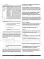
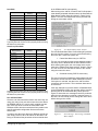
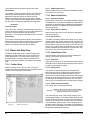
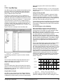
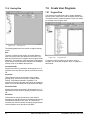
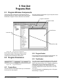
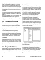
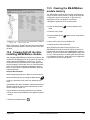
3.3 How PowerTools Pro is
Organized
The PowerTools Pro software is made up of six major
components. These components are the Menu Bar, Tool
Bar, Hierarchy, View, View Tab, and Status Bar. Note that
some of these components and sub-components are only
available under certain conditions (i.e., while online, while
on a certain view, etc.).
Figure 6:
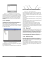
Figure 4:
Control Techniques’ North America
Website
PowerTools Pro Organization
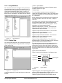
3.3.1 Menu Bar
SM-EZMotion Software Screen
Once the button is clicked the installation will begin. Follow
the installation instructions to complete the software
installation.
Figure 7 shows the Menu Bar as found in PowerTools Pro.
The items available on the Menu Bar may change under
certain conditions (i.e., online, configuration open, etc.).
3.2.2 From the Web
PowerTools Pro can be downloaded from the Control
Techniques website at the following address:
www.emersonct.com.
Figure 7:
Menu Bar
To use a menu choose one of the following methods:
• On the menu bar, click a menu name to display a list
of options. On the menu, either click an option or use
PowerTools Pro Configuration Software
www.controltechniques.com
7
the DOWN ARROW to move down the list, and then
press ENTER.
• Press ALT and press the underlined letter in the
menu name. Then press the underlined letter in the
option name. For example, to open a new
configuration file, press ALT and press F to open the
File menu. Then press N for New, see Figure 8.
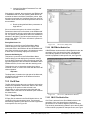
3.3.1.1 File
The File menu on the Menu Bar contains many different
options for file handling (i.e., saving files, importing files,
etc.). Figure 8 below shows the File menu expanded.
3.3.1.1.5 Save As...
Save As allows the user to save the active file using a
different name or to save an existing file to a different
directory location. Navigate to the directory to which the file
is to be saved, and click on the Save button.
3.3.1.1.6 Import
Import allows the user to import an existing FM-3 file into
an FM-4 configuration, or an existing FM-3 or FM-4 file into
an SM-EZMotion configuration. To import the file, open a
new file and select the configuration type that you wish to
convert to. Once the new file (of the desired configuration
type) is open, select Import, and find the file that is to be
converted. Select the file to be converted, and then click
Open. The existing file will then be converted into the new
file type. The new file must then be saved with the new file
name and extension.
3.3.1.1.7 Print
Print will send the active file to the printer specified by the
user. A Print Options box will open allowing the user to
specify which sections of the configuration are to be
printed. By default, all sections will be printed. To remove
a given section from the printout, uncheck the specific box
by clicking on the check mark.
3.3.1.1.8 Print Preview
Print Preview will open a new window that displays what an
actual hardcopy printout would look like. This can be
helpful to determine if formatting is correct.
3.3.1.1.9 Print Setup
Figure 8:
Selecting Print Setup allows the user to change the Target
Printer, Paper Type, Paper Source, Print Orientation, and
other printer related parameters.
File Menu
3.3.1.1.1 New
3.3.1.1.10 Recently Used Files
New will open a new PowerTools Pro file. The user will be
asked what type of configuration to create (FM-3, FM-4, or
SM-EZMotion). For all modules used with the Unidrive SP,
select SM-EZMotion Setup.
Also displayed on the File Menu are the last four files that
were edited using PowerTools Pro. To quickly access one
of these last four files, simply click on the file name in the
File Menu. Clicking on one of these files will open the
configuration for editing.
3.3.1.1.2 Open
Open allows the user to open an existing application
created with PowerTools Pro. Navigate to the directory that
the desired file is located in, and double-click on the
specific file. Doing so will open the file for editing.
3.3.1.1.3 Close
Close will close the active configuration. If multiple files are
open, the active file’s Title Bar will be highlighted.
3.3.1.1.4 Save
Selecting Save will save the active file on the users PC.
The location to which the file is saved is based on where
the file was previously saved. If the file has not yet been
saved, the Save As control box will open instead.
8
www.controltechniques.com
SM-EZMotion Module User Guide
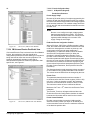
3.3.1.2 Edit
3.3.1.2.6 Replace
Figure 9 shows the Edit Menu as selected from the
PowerTools Pro Menu Bar.
Selecting Replace bring up the Find window (see Find
above) with an additional parameter called Replace With.
Using this method will search the user program for text that
matches the text in the Find What field, and replace it with
the text in the Replace With field. The user can select to
replace just the next match, or all existing matches with the
Replace All button.
3.3.1.2.7 New
Selecting New will bring up a sub menu allowing the user
to add a new Index, Home, or Program. Indexes, Homes,
and Programs may not be added while online with the
SM-EZMotion.
3.3.1.2.7.1 Index
Selecting Undo will undo the last change made to a user
program. Up to the last ten changes made can be undone.
Selecting New > Index will add a new index to the
configuration. Indexes are added in sequential order. The
new index will be the next highest available index number.
Adding an index will take you directly to the new index
view.
3.3.1.2.2 Cut
3.3.1.2.7.2 Home
Selecting Cut will remove the selected text from a user
program. To select text in a program, place the mouse
pointer at the leftmost character to be selected, then press
and hold the left mouse button dragging the cursor over the
text until the mouse pointer is positioned over the final
desired character, then release the mouse button. Once
the text is selected, the text can be cut, copied, or pasted.
Only one home is available in the initial release of the
SM-EZMotion
Figure 9:
Edit Menu
3.3.1.2.1 Undo
3.3.1.2.3 Copy
3.3.1.2.7.3 Program
Selecting Edit > New > Program will add a new user
program to the configuration. Programs are added in
sequential order. The new program will be the next highest
available program number. Adding a program will take you
directly to the new program view.
Selecting Copy will copy any selected text in a user
program. To select text in a program, place the mouse
pointer at the leftmost character to be selected, then press
and hold the left mouse button dragging the cursor over the
text until the mouse pointer is positioned over the final
desired character, then release the mouse button. Once
the text is selected, the text can be cut, copied, or pasted.
3.3.1.2.8 Delete
3.3.1.2.4 Paste
To delete an index, the user must select the specific index
they wish to delete on the hierarchy. Once the index is
selected, click on Edit > Delete > Index on the Menu Bar.
Doing so will delete the index instance. Once the index is
deleted, the data stored on the index view cannot be
recovered.
Selecting Paste will place the last cut or copied text into a
user program. See Cut and Copy above for further
information.
3.3.1.2.5 Find
Selecting Find will bring up the Find window. In the find
window, the user can type in a specific word, number, or
any character that they wish to find in a user program.
Once the user enters the text they wish to find, the Find
Next or Mark All button is clicked. The Find Next button will
highlight the next segment of code after the cursor that
matches the search text. The Mark All button will put a
mark next to each line of the program that has matching
text. The user also has several other options on searching
the program for matching text.
PowerTools Pro Configuration Software
Selecting Delete will bring up a sub menu allowing the user
to delete an existing Index, Home, or Program. Indexes,
Homes, and Programs may not be deleted while online
with the SM-EZMotion.
3.3.1.2.8.1 Index
3.3.1.2.8.2 Home
Homes cannot be deleted in the initial release of
SM-EZMotion.
3.3.1.2.8.3 Program
To delete a program, the user must select the specific
program they wish to delete on the hierarchy. Once the
program is selected, click on Edit > Delete > Program on
the Menu Bar. Doing so will delete the program instance.
Once the program is deleted, the program code cannot be
recovered.
www.controltechniques.com
9
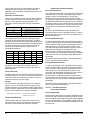
3.3.1.3 Device
Figure 10 shows the Device Menu as selected from the
PowerTools Pro Menu Bar.
allows the user to send changes to the system without
requiring a complete download. Certain parameters when
changed require a complete download and cannot be sent
to RAM. If one of these parameters is changed, the Update
Drive option will not be available on the Edit menu.
3.3.1.3.7 Reset Errors
Selecting Reset Faults will clear any active Errors or Trips.
If the trip condition still exists, the trip may reactivate
immediately after clearing it.
3.3.1.3.8 View Faults
Selecting View Faults from the Edit menu will open the
Active Faults pop up window. The Active Faults window will
show any fault conditions that have not been reset.
3.3.1.3.9 Reboot Drive
Figure 10:
Selecting Reboot will cause the SM-EZMotion to reboot
itself (similar to cycling power). Rebooting will cause
PowerTools Pro to lose communications with the
SM-EZMotion module.
Device Menu
3.3.1.3.1 Change Address
3.3.1.3.10 Feedhold
Selecting Change Address from the Device menu allows
the user to change the Modbus node address of a drive/
module system. The user must be online with the device for
Change Address to be available. The user will be prompted
for the new node address. After entering the new node
address, click OK. The drive will immediately change to the
new address.
3.3.1.3.2 Change Baud Rate
Selecting Change Baud Rate from the Device menu allows
the user to change the Baud Rate for the application stored
in the SM-EZMotion. If the baud rate setting in PowerTools
Pro does not match the baud rate for the application,
PowerTools will not be able to communicate with the
SM-EZMotion module.
3.3.1.3.3 Download
Selecting Download will send the active configuration from
the PC to the target node address (specified on the Setup
view). For more information on Downloading, see Section
4 - Communications in this manual.
Selecting Feedhold will put the SM-EZMotion module into
a feedhold condition. Feedholding is a means of pausing
motion that is active. For more information on Feedhold,
see Section 8 - Starting and Stopping Motion in this
manual.
3.3.1.3.11 Where Am I? (Global)
Selecting Where Am I? will launch a utility that shows the
user what line in a user program is currently being
processed. If multiple user programs are running
simultaneously, the user will be asked to specify which task
they wish to follow. A blue arrow will appear next to the
active line of the program. The global Where Am I will
continuously update until it is deactivated. This is different
from the Where Am I found on the Program Toolbar.
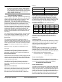
3.3.1.4 Options
Figure 11 shows the Options Menu as selected from the
PowerTools Pro Menu Bar.
3.3.1.3.4 Disconnect
Selecting Disconnect will terminate communications
between the PC and any nodes the PC is online with.
3.3.1.3.5 Upload Drive
Upload Drive will upload only the node address specified in
the active configuration. To use Upload Drive, open a new
file and set the Node Address on the setup view to the
address you wish to upload. Then select Upload Drive.
This will overwrite the active configuration with the
uploaded data.
3.3.1.3.6 Update Drive
Figure 11:
Options Menu
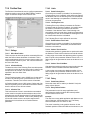
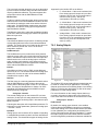
3.3.1.4.1 Preferences
Underneath the Preferences menu option, there are three
sub-options: Communications, User Levels, and
PowerTools Operation. Selecting one of these sub-options
allows the user to configure the preferences related to that
specific topic.
Selecting Update Drive will send any parameters that have
been changed since the last download into RAM. Doing so
10
www.controltechniques.com
SM-EZMotion Module User Guide
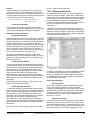
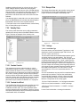
3.3.1.4.1.1 Communications
Selecting Options > Preferences > Communications will
launch the Modbus Setup window as seen in Figure 12.
Figure 14:
Figure 12:
Modbus Setup Window
On the Modbus Setup window, the user can configure the
maximum node address they wish to poll for when
uploading devices or flash upgrading devices. PowerTools
Pro will not check to see if any devices with node
addresses higher than the number entered are available
on the network.
To change the COM port number and Baud Rate, the user
must click the Configure Serial Port button. Once the COM
port and Baud Rate are selected, click OK.
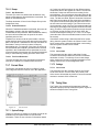
Figure 13:
User Levels
If a given user level is set to "Easy Mode", then only
parameters used in the most basic applications are
available. If user level is set to "Detailed Mode", then the
most commonly used parameters are available. If user
level is set to "Too Much Mode", then all parameters will be
visible. This feature is designed to make the most common
parameters easier to find and use in programs,
assignments, and throughout the software.
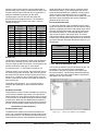
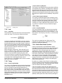
3.3.1.4.1.3 Ptools Operation
Selecting Options > Preferences > Ptools Operation allows
the user to configure certain setting for the way
PowerTools Pro software functions. Figure 15 shows the
PowerTools preferences window.
Com Port and Baud Rate Setup
3.3.1.4.1.2 User Levels
Selecting Options > Preferences > User Levels allows the
user to change the quantity and complexity of available
parameters.
Figure 15:
PowerTools Preferences
This window is used to configure several options related to
downloading files, uploading files, and file saving. Once the
PowerTools Pro Configuration Software
www.controltechniques.com
11
parameters have been set in this window, the user will no
longer be prompted with pop-ups when the upload or
download files.
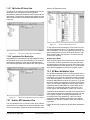
Once PowerTools detects devices, a window similar to that
shown in Figure 17 will appear.
For more information on these options, refer to Section 4 Uploading and Downloading Using PowerTools Pro in this
manual.
3.3.1.5 Tools
Figure 16 shows the Tools Menu as selected from the
PowerTools Pro Menu Bar.
Figure 17:
Figure 16:
Tools Menu
3.3.1.5.1 Watch Window
Selecting Watch Window will launch a diagnostics tool that
allows the user to view the current value of multiple
SM-EZMotion module parameters while online with the
module. For more information on the Watch Window, refer
to Section 11 - Diagnostics of this manual.
3.3.1.5.2 Drive Menu
The Drive Menu Watch Window allows the user to read or
write a single SP Menu Parameter from within PowerTools
Pro.
Reading a Menu Parameter
To read a Menu Parameter, enter the Menu Parameter
number to be read in the Menu.Parameter box. The Menu
Parameter is entered using the MM.PP format (where MM
is the Menu number and PP is the parameter number).
Once the Menu parameter is entered, then click on the
Read button. The value read from the Unidrive SP will be
displayed in the Parameter Data box.
Flash Upgrade Window
To upgrade the firmware in a given node, click on the
Select File button in the top-right corner of the window.
Navigate to the folder location where the new flash file is
stored. Select the new flash file and click Open. If the
selected flash file is compatible with the devices in the list,
the LED next to the device will turn from red to green. If the
selected flash file is not compatible with the device, the
LED will remain red. Once the LED next to the desired
device has turned green, click on the device to be
upgraded so that it is highlighted, then click the Upgrade
button.
The upgrade process can take up to fifteen minutes (at
19200 baud). When complete, cycle power on the system
for the new firmware to take effect.
3.3.1.6 View
Figure 18 shows the View Menu as selected from the
PowerTools Pro Menu Bar.
Writing to a Menu Parameter
To write to a Menu Parameter, enter the Menu Parameter
number to be read in the Menu.Parameter box. The Menu
Parameter is entered using the MM.PP format (where MM
is the Menu number and PP is the parameter number).
Once the Menu parameter is entered, then enter the value
to be written to that parameter in the Parameter Data box.
Then click on the Write button. The value in the Parameter
Data box will be written to the specified Menu Parameter.
If the user wishes to verify that the data was written
properly, they could either click the Read button, or
navigate to the parameter using the SP keypad manually.
3.3.1.5.3 Flash Upgrade
Selecting Flash Upgrade will launch the utility that lets the
user upgrade the firmware in the SM-EZMotion module.
New firmware becomes available from Control Techniques
to add new features or to upgrade prior releases.
When the user selects Flash Upgrade, PowerTools Pro will
search for all devices available on the Modbus network.
12
Figure 18:
View Menu
3.3.1.6.1 Toolbar
By default, the Toolbar is visible on the PowerTools Pro
screen. To hide the Toolbar, select Toolbar to remove it
from the display. If the Toolbar is not visible, select Toolbar
to make it appear again.
3.3.1.6.2 Status Bar
By default, the Status Bar is visible on the PowerTools Pro
screen. To hide the Status Bar, select Status Bar to remove
it from the display. If the Status Bar is not visible, select
Status Bar to make it appear again.
3.3.1.6.3 Show Navigation Tree
By default, the Hierarchy is visible on the PowerTools Pro
screen. Some users with low resolution monitors wish to
www.controltechniques.com
SM-EZMotion Module User Guide
hide the Hierarchy to allow for more room while
programming. To hide the Hierarchy, select Show
Navigation Tree to remove it from the display. If the
Hierarchy is not visible, select Show Navigation Tree to
make it appear again.
3.3.1.8.2 Using Help
3.3.1.7 Window
3.3.1.8.3 About PowerTools...
Figure 19 shows the Window Menu as selected from the
PowerTools Pro Menu Bar.
About PowerTools Pro will bring up a window that shows
what revision of PowerTools Pro software is currently
running.
Selecting Using Help will launch a window that lets the user
select different topics available as part of the help file. This
utility makes it easier to navigate the different sections of
the help file.
3.3.2 Tool Bar
3.3.2.1 New
Figure 19:
Same as File > New from the Menu Bar. Selecting New will
open a new PowerTools Pro file. The user will be asked
what type of configuration to create (FM-3, FM-4, or
SM-EZMotion). For modules used with the Unidrive SP,
select SM-EZMotion Setup.
Window Menu
3.3.1.7.1 Arrange Icons
No function.
3.3.1.7.2 Cascade
If the user has multiple configurations open
simultaneously, selecting Cascade will neatly layer the
windows so the title bars are visible and the active
configuration is in front.
3.3.1.7.3 Tile
If the user has multiple configurations open
simultaneously, selecting Tile will resize each of the
windows to have equal area on the screen. The active
configuration will have a highlighted Titlebar on the
window.
3.3.2.2 Open
Same as File > Open from the Menu Bar. Selecting Open
will allow the user to open an existing application created
with PowerTools Pro. Navigate to the directory that the
desired file is located in, and double-click on the specific
file. Doing so will open the file for editing.
3.3.2.3 Save
3.3.1.7.4 Current Files Open
If the user has multiple configurations open
simultaneously, each of the open files will be listed on the
Window menu. The active file will have a check mark next
to it as seen in Figure 19. By selecting a different file from
this list, the selected file will become the active file.
3.3.1.8 Help
Figure 20 shows the Help Menu as selected from the
PowerTools Pro Menu Bar.
Figure 20:
Help Menu
3.3.1.8.1 Help Topics
By selecting Help Topics, the help file will be launched
allowing the user to lookup and read information related to
the SM-EZMotion module and PowerTools Pro software.
PowerTools Pro Configuration Software
Same as File > Save from the Menu Bar. Selecting Save
will save the active file on the users PC. The location to
which the file is saved is based on where the file was
previously saved. If the file has not yet been saved, the
Save As control box will open instead.
3.3.2.4 Print
Same as File > Print from the Menu Bar. Selecting Print will
send the active file to the printer specified by the user. A
Print Options box will open allowing the user to specify
which sections of the configuration are to be printed. By
default, all sections will be printed. To remove a given
section from the printout, uncheck the specific box by
clicking on the check mark.
www.controltechniques.com
13
3.3.2.5 Upload
between the PC and any nodes the PC is online with.
3.3.2.11 Add Index
Same as Device > Upload from the Menu Bar. Selecting
Upload will scan the Modbus network for available nodes,
and then upload the specified node address
configurations. Upload is only available if a configuration is
not already open.
3.3.2.6 Download
Same as Edit > New > Index from the Menu Bar. Selecting
Add Index will add a new index to the configuration.
Indexes are added in sequential order. The new index will
be the next highest available index number. Adding an
index will take you directly to the new index view. Can not
be used while online.
3.3.2.12 Delete Index
Same as Device > Download from the Menu Bar. Selecting
Download will send the active configuration from the PC to
the target node address (specified on the Setup view). For
more information on Downloading, see “Communications”
on page 17 in this manual.
3.3.2.7 Upgrade Configuration
Same as Edit > Delete > Index from the Menu Bar. To
delete an index, the user must select they specific index
they wish to delete on the hierarchy. Once the index is
selected, click on Delete Index on the Tool Bar. Doing so
will delete the index instance. Once the index is deleted,
the data stored on the index view cannot be recovered.
Can not be used while online.
Same as Device > Convert from the Menu Bar.
3.3.2.13 Add Program
3.3.2.8 Send to RAM
Same as Device > Update Drive from the Menu Bar.
Selecting Update Drive will send any parameters that have
been changed since the last download into RAM. Doing so
allows the user to send changes to the system without
requiring a complete download. Certain parameters when
changed require a complete download and cannot be sent
to RAM. If one of these parameters is changed, the Update
Drive option will not be available on the Edit menu.
Parameter values only sent to RAM will be list when power
is cycled.
3.3.2.9 Upload NVM
Selecting Upload NVM (Non-Volatile Memory) will read the
current value from each of the parameters in the
SM-EZMotion module’s NVM memory and display it in the
PowerTools Pro configuration. The file can then be saved
to retain the current values stored in NVM.
3.3.2.10 Disconnect
Same as Edit > New > Program from the Menu Bar.
Selecting Add Program will add a new user program to the
configuration. Programs are added in sequential order.
The new program will be the next highest available
program number. Adding a program will take you directly to
the new program view. Can not be used while online.
3.3.2.14 Delete Program
Same as Edit > Delete > Program from the Menu Bar. To
delete a program, the user must select they specific
program they wish to delete on the hierarchy. Once the
program is selected, click on Delete Program on the Tool
Bar. Doing so will delete the program instance. Once the
program is deleted, the program code cannot be
recovered. Can not be used while online.
3.3.2.15 View Current Errors
Same as Device > View Errors... from the Menu Bar.
Selecting View Errors... from the Edit menu will open the
Active Errors pop up window. The Active Errors window will
show any error or trip conditions that have not been reset.
Same as Device > Disconnect from the Menu Bar.
Selecting Disconnect will terminate communications
14
www.controltechniques.com
SM-EZMotion Module User Guide
3.3.2.16 Clear Errors
Same as Device > Reset Errors from the Menu Bar.
Selecting Reset Errors will clear any active errors. If the
fault condition still exists, the error may reactivate
immediately after clearing it.
user what line in a user program is currently being
processed. If multiple user programs are running
simultaneously, the user will be asked to specify which
Task they wish to follow. A blue arrow will appear next to
the active line of the program. The global Where Am I will
continuously update until it is deactivated. This is different
from the Where Am I found on the Program Toolbar.
3.3.2.22 Hide/Show Hierarchy
3.3.2.17 Watch Window
Same as Tools > Watch Window from the Menu Bar.
Selecting Watch Window will launch a diagnostics tool that
allows the user to view the current value of multiple
SM-EZMotion parameters while online with the module.
For more information on the Watch Window, refer to
“Diagnostics” on page 137 of this manual.
Same as View > Show Navigation Tree on the Menu Bar.
By default, the Hierarchy is visible on the PowerTools Pro
screen. Some users with low resolution monitors wish to
hide the hierarchy to allow for more room while
programming. To hide the hierarchy, select Hide/Show
Hierarchy from the Tool Bar to remove it from the display.
If the hierarchy is not visible, select Navigation Tree to
make it appear again.
3.3.2.18 Drive Watch Window
3.3.2.23 Help Contents
Selecting Drive Watch Window will launch a diagnostics
tool that allows monitoring and editing of individual drive
menu parameters while online. For more information see
“Drive Menu” on page 12.
Same as Help > Help Topics on the Menu Bar. By selecting
Help Contents, the help file will be launched allowing the
user to lookup and read information related to the
SM-EZMotion module and PowerTools Pro software.
3.3.2.19 Stop
3.3.2.24 Context Sensitive Help (CSH)
Using the Stop button on the Tool Bar will stop all motion
and programs that are currently active in the
SM-EZMotion. The Stop button will toggle on and off
meaning that once it is clicked to stop motion and
programs, it will remain active until it is clicked again. Until
the Stop is toggled off, motion and program will be
prevented from being initiated.
Using Context Sensitive Help (or CSH) will show detailed
information from the help file related to the object that is
clicked with the mouse. To use Context Sensitive Help,
click on the CSH button on the Tool Bar, the mouse graphic
will turn from a pointer to a pointer with a question mark
next to it. Once the mouse pointer graphic changes, click
on the parameter on any of the PowerTools Pro views that
the user wants help information for.
3.3.2.20 Feedhold
3.3.3 Hierarchy
Same as Device > Feedhold from the Menu Bar. Selecting
Feedhold will put the SM-EZMotion into a feedhold
condition. Feedholding is a means of pausing motion that
is active. For more information on Feedhold, see “Starting
and Stopping Motion” on page 93 in this manual.
3.3.2.21 Global Where Am I?
Same as Device > Where Am I? from the Menu Bar.
Selecting Where Am I? will launch a utility that shows the
PowerTools Pro Configuration Software
Figure 6 shows the Hierarchy as found in PowerTools Pro.
The Hierarchy is a navigational aid that helps the user step
through a configuration. The different parameters related
to configuring the system are grouped into logical groups
and placed on different Views within the software. To see
a certain View, the user simply selects that View from the
Hierarchy. Once the user clicks on a given branch on the
Hierarchy, that view is then displayed on the right-hand
side of the screen.
Groups on the hierarchy can be expanded and collapsed
much like with Windows Explorer. To expand a group of
views, click on the “+” symbol next to the grouping. Doing
so will show each of the branches available within that
www.controltechniques.com
15
group. To collapse a group on the Hierarchy, click on the
“-“symbol next to the grouping. Doing so will hide all of the
branches within that group.
Natural progression through the hierarchy, starting at the
top, and working towards the bottom will step the user
through the entire configuration. The Hierarchy starts at the
top with Hardware, then moves on to Setup parameters, I/
O Setup, Motion, and then finishes with Programs. When
the user gets to the bottom of the hierarchy, the
configuration should be ready to be downloaded to the
module.
3.3.4 View
Figure 6 shows an example of a View in PowerTools Pro.
A View will typically contain text boxes, list boxes, check
boxes, or other windows editing mechanisms. The Views
are designed to separate parameters into logical groups so
that they are easier to find and use. The View that is visible
at any time is dependant upon what branch is selected on
the Hierarchy. To see a specific View, it must be selected
on the PowerTools Pro hierarchy.
3.3.5 View Tabs
Some Views in PowerTools Pro (see explanation of View
above) have tabs, in the bottom half of the View to organize
more specific parameters. Some examples of View Tabs
are Calculations and Online. An Online Tab is only visible
when online (connected) with a module.
On the Calculations Tab the user will find simple
calculations to help realize how much time a motion will
take, or how much time or distance is covered during
certain segments of a motion profile. On the Index –
Calculation Tabs, a graph is created based on data
entered by the user to give some visualization of what the
profile looks like.
The Online Tab is used to show feedback and other
diagnostic information to the user while online with a
module. The parameters shown on an Online view will
change depending on which View is being displayed.
PowerTools Pro must be online in order to see the Online
Tab.
3.3.6 Status Bar
The Status Bar is used to give quick diagnostic information
to the user about the status of the drive/module, what
motion is active, Position and Velocity Feedback, and
Online Status. For more details, see the “Diagnostics” on
page 137.
16
www.controltechniques.com
SM-EZMotion Module User Guide
4 Communications
Bar. Figure 22 shows the Modbus Setup window that
allows the user to configure the communication settings.
4.1 Communications Protocol
PowerTools Pro communicates with the SM-EZMotion
module using 32-bit Modbus RTU protocol.
4.2 Connecting the PC to the
SM-EZMotion Module
The SM-EZMotion module communicates with the PC
through the Unidrive SP's communications port. An
RS-232 to RS-485 converter is necessary to communicate
with the Unidrive SP. The Unidrive SP has an RJ45 serial
port connector on the front of the drive.
Control Techniques offers a pre-made cable for this
purpose called “CT Comms Cable" (previously named
SE71). Figure 21 shows the CT Comms Cable.
Figure 22:
Modbus Setup
In the Modbus Setup window, the user can configure the
maximum node address they wish to poll for when
uploading devices or Flash Upgrading devices.
PowerTools Pro will not check to see if any devices with
node addresses higher than the number entered are
available on the network.
To change the COM port number and Baud Rate, the user
must click the Configure Serial Port button. Figure 23
shows the Communications Setup window.
Figure 21:
CT Comms Cable
The RJ45 connector is located under a small rubber flap on
the front of the Unidrive SP just below the keypad. The
pin-out for this connector is described in the table below.
Pin
Function
1
Termination Resistor
2
RX TX
3
0V
4
+24V
5
Not Used
6
TX Enable
7
RX\ TX\
8
Linked to Pin 7
Figure 23:
Communications Setup
Once the COM port and Baud Rate are selected, click OK.
When SM-EZMotion modules are shipped from the factory,
they are configured to communicate at a baud rate of
19200 baud.
4.4 Uploading and Downloading
using PowerTools Pro
4.3 Configuring Communications
in PowerTools Pro
Figure 24 will be used throughout the Uploading and
Downloading section of the manual to describe certain
processes.
Before attempting to upload or download a configuration
using PowerTools Pro, the software must be configured to
the correct communications settings. To configure
communications, open PowerTools Pro then click on
Options > Preferences > Communications on the Menu
Communications
www.controltechniques.com
17
SM-EZ Motion Module
H
User NVM
PC with PowerTools Pro
PowerTools Pro configuration file (Arrow A in Figure 24). At
the completion of the upload, the user will be asked if they
wish to upload the NVM values. This dialog box is shown
below.
A
B
Non-User NVM
D
E
C
F
RAM
G
Figure 25:
Figure 24:
Memory Storage in the SM-EZMotion
Module
4.4.1 Uploading
Uploading is the process of reading the configuration
stored in the SM-EZMotion module and loading that data
into a file on the PC. Arrow B in Figure 24 represents a
standard Upload. To upload a configuration from the
SM-EZMotion module, first make sure the communications
settings are correct, and then click the Upload button on
the PowerTools Pro toolbar or select Device menu, Upload
command from the Menu Bar.
Upload NVM Option Window
By selecting Yes, the values of all parameters stored in
NVM will be uploaded and entered into the PowerTools Pro
configuration file values (Arrow H in Figure 24). If No is
selected, the values entered into the PowerTools Pro
configuration file will remain the same as those that were
last downloaded to the SM-EZMotion module.
4.4.3.2 Downloading
When downloading to the SM-EZMotion module the user
will be required to select how to handle the NVM
parameters upon downloading. Figure 26 shows the dialog
box asking the user to select one of three options for the
download.
4.4.2 Downloading
Downloading is the process of sending the PowerTools Pro
configuration from the PC to the SM-EZMotion module.
Changes made in PowerTools Pro will not take effect until
the information has been downloaded or the Update to
RAM button has been clicked. Arrow A in Figure 24
represents a standard Download. To download information
to a SM-EZMotion module, click on the Download button
on the PowerTools Pro Tool Bar or select Device >
Download from the Menu Bar.
The first time a download is performed, PowerTools Pro
will lead the user through a series of dialog boxes to
configure the baud rate and COM port of the PC to be
used.
4.4.3 Non-Volatile Memory (NVM) Options for
Uploading and Downloading
When Uploading or Downloading, the user may be
presented with options on how to handle the values stored
in NVM memory. NVM is a type of memory that does not
lose its contents when power is removed. Values in RAM
are lost on power down, while values in NVM are retained.
Following is a description of the options the user may
encounter while uploading or downloading.
4.4.3.1 Uploading
When uploading from a SM-EZMotion module, the values
that were last downloaded are uploaded and put into a
18
Figure 26:
Download NVM Option Window
A description of each of the options is as follows:
Overwrite
This option will overwrite all the parameters stored in NVM
with the current values in the user configuration (Just Arrow
A in Figure 24). The values that are in NVM prior to the
download will be lost.
Update
This option will upload the current NVM parameter values
from the SM-EZMotion module and enter them into the
user configuration. Once the NVM values have been
stored in the file, the file is fully downloaded (First Arrow H
followed by Arrow A in Figure 24. Data from H is saved in
PowerTools Pro configuration).
www.controltechniques.com
SM-EZMotion Module User Guide
Keep
This option will download the entire user configuration, but
then NVM parameters will be restored to the value prior to
download. This is similar to the Update option, but the
Keep option does not upload the NVM values into the user
configuration (First Arrow H followed by Arrow A, but data
from H is not stored in PowerTools Pro file).
Modify Parameter
Values
Click the
Update to RAM
icon
The table below shows an example of how these three
options work:
Value Before
Download
PowerTools
Pro Value for
Index.0.Vel
150
NVM Value for
Index.0.Vel
500
Value After Download
Overwrite
Option
Update
Option
Keep
Option
150
500
150
More
Changes
Required?
NO
Perform a
full Download
YES
150
500
500
Figure 27:
4.4.4 Updating to RAM
The Update to RAM button can be used to send changes
to the SM-EZMotion module without performing a complete
download (symbolized by Arrow F in Figure 24). The
Update to RAM button is found in the PowerTools Pro
toolbar. This operation will send only those changes that
have been made since the last Update to RAM or Device >
Download to the SM-EZMotion module. The changes will
take effect immediately upon clicking on the button.
The changed parameters will be sent to the SM-EZMotion
module without stopping motion or disabling the drive.
Because of this, it is important to use caution when
changing motion parameters while the motor is in motion.
The Update to RAM button saves the parameters only to
RAM and not to Non-Volatile Memory (NVM). Therefore, if
the system power is removed, any changes made using
the Update to RAM button will be lost. In order to save
changes to NVM, a full-download must be performed.
The flowchart in Figure 27 describes a typical process
using the Update to RAM to make changes, and then
downloading when complete to save changes to NVM.
Update to RAM flowchart
The Update to RAM button operates according to the
following rules:
• If no parameters have been modified, the Update to
RAM button will be disabled.
• If the user modifies a parameter that does not require
a full download, the Update to RAM button will
become enabled.
• If while the button is enabled, the user modifies a
parameter that requires a full download, the Update
to RAM button will become disabled.
• When the user clicks on the Update to RAM button,
all the modified parameters are transmitted to the
SM-EZMotion module. Once transmitted, the button
will become disabled again until another parameter
is changed.
• If the user performs a full download while the button
is enabled, the Update to RAM button will be
disabled when the download is complete.
• If the user modifies parameters, and then
disconnects (stops communications), the update
button will be disabled, and the changes will not be
sent.
4.4.5 PowerTools Pro Operation Preferences
To avoid getting all the option windows described above
every time an Upload or Download is performed, the user
can set certain preferences. To configure the preferences,
select Options > Preferences > Ptools Operation from the
Menu Bar. Figure 28 shows the Preferences Configuration
window.
Communications
www.controltechniques.com
19
Options above.
4.4.5.1.4 Keep - Remember the values and restore them after the
download
When this radio button is selected the "Keep" option will be
used on every download to the module. For more details on
how the Keep option works, see the Download NVM
Options above.
4.4.5.1.5 Ask on each download
When this radio button is selected, the user will be
prompted on every download to select either the Overwrite,
Update, or Keep option. This is the default preference
setting.
4.4.5.2 Upload Non-Volatile Memory (NVM) Group
4.4.5.2.1 Always upload NVM
Following is a description of each of the preference
settings:
When uploading a configuration, PowerTools Pro uploads
from a Non-User NVM location, so the data uploaded only
matches exactly what was last downloaded. If any
parameters in the Save to NVM list have changed since the
last download, those new values would not be uploaded.
By selecting this radio button, the parameter values in the
Save to NVM list will be uploaded into the PowerTools Pro
configuration after the normal upload.
4.4.5.1 Download Group
4.4.5.2.2 Always bypass NVM upload
4.4.5.1.1 Ignore saving file on Ptools/Drive revision conversion
When uploading a configuration, PowerTools Pro uploads
from a Non-User NVM location, so the data uploaded only
matches exactly what was last downloaded. By selecting
this radio button, the parameter values in the Save to NVM
list will NOT be uploaded.
Figure 28:
PowerTools Pro Operation Preferences
Window
On a download PowerTools Pro first checks the revision of
the SM-EZMotion module firmware before downloading
the configuration. If the firmware in the module is older than
the matching software revision, PowerTools Pro then
converts the user configuration to match the firmware
revision in the module. Because certain parameters may
need to be changed to match the firmware revision,
PowerTools asks the user if they wish to save the file
before it is converted. If the user wishes to download
without saving every time, and therefore avoid being asked
on every download, this checkbox should be checked.
4.4.5.1.2 Overwrite - Reset the NVM configuration
When this radio button is selected the "Overwrite" option
will be used on every download to the module. For more
details on how the Overwrite option works, see the
Download NVM Options above.
Note
Note: It is required to Overwrite the Non-Volatile
Memory on the first download to the module since
no Non-Volatile Memory parameters have been
loaded into the drive on initial startup.
4.4.5.1.3 Update - Upload the values into the current Update
PowerTools Pro configuration
4.4.5.2.3 Ask on each upload
When this radio button is selected, PowerTools Pro will ask
the user via a pop-up window whether to upload the NVM
or to bypass the NVM upload on every upload.
4.4.6 Secure Downloading
The Secure Download feature allows the user to download
a configuration that prevents anyone from uploading the
file, or going online with the system. This is used to protect
a file from being accessed by unauthorized personnel. If a
secure file is downloaded to the SM-EZMotion module, all
diagnostics capabilities in the software are lost. The only
way to go online with the system again is to download the
original (non-secure) file over the secure version, or to
download a completely new file.
Before performing a secure download, the file must first be
saved in the secure file format. To do this, open the file you
wish to save in the secure format using PowerTools Pro.
Then click File > Save As on the Menu Bar. The following
Save As window should appear on your screen.
When this radio button is selected the "Update" option will
be used on every download to the module. For more details
on how the Update option works, see the Download NVM
20
www.controltechniques.com
SM-EZMotion Module User Guide
Figure 31:
Figure 29:
Upload Failure - File Protected By User
message
Secure File - Save As Window
On this window, select the "Save also as secure download
format" check box located at the bottom of the window,
then click Save. Doing so will save your file in BOTH the
standard file format (.EZ), as well as in the secure file
format (.EZs).
The "s" at the end of the file extension stands for "secure".
The secure file will be saved to the same directory as the
standard file. To perform the Secure Download, close all
open files in PowerTools Pro, click on Device menu,
Secure Download command as shown in Figure 30.
Figure 30:
Secure File Download
A window will then open asking the user to select the
secure file they wish to download. Select the secure file
that was just saved, and click Open. This will download the
secure file to the target device.
A secure file (.EZs) cannot be opened or modified. The file
extension cannot be changed to allow the user to open it.
The secure file is only valid for use by the secure download
function. If a user attempts to upload a secure file, a
message will appear indicating that the file that resides in
the SM-EZMotion module has been protected by the user.
An example of this message is shown in Figure 31.
Communications
www.controltechniques.com
21
22
www.controltechniques.com
SM-EZMotion Module User Guide
5 How Motion
Works
5.1 Introduction
The SM-EZMotion module offers four different motion
object types. These four types are Jog, Home, Index, and
Gear. All motion objects run on what is called a Profile.
Only one motion object can run on a Profile at a time. For
applications that need to run multiple motion objects
simultaneously, the SM-EZMotion module has two
different Profiles. This will be discussed further in the
Summing Multiple Profiles subsection below.
This section will concentrate on how the different motion
objects work, and not on how they are configured using
PowerTools Pro. For more information on how to configure
the motion objects in PowerTools Pro, see “Configuring an
Application” on page 33.
5.2 Jog
Jog is a motion object that has Acceleration, Velocity, and
Deceleration, but no dedicated distance. The user pressing
a push button or foot pedal often controls jog motion. When
the user presses the Jog button, the jog accelerates up to
the jog velocity and continues to run at that velocity until the
user releases the Jog button. When the user releases the
Jog button, the jog decelerates from the Jog Velocity back
down to zero velocity (stopped).
Figure 32shows an example of a Jog profile.
Velocity
decelerate to a stop immediately (called Calculated
Offset), or continues at the Home velocity and comes to a
stop a specified distance from where the reference signal
activated (called Specified Offset).
The Home is typically used to define a reference position
(or Home position) on a machine. This can be done in
several different ways depending on what type of Home
Reference is used. The Home Reference determines what
action or signal defines the Home position. The three types
of Home Reference supported by the SM-EZMotion
module are Marker, Sensor, and Sensor then Marker.
Following is a description of the three different Home types.
5.3.1 Home to Marker
Most motors used with the Unidrive SP have an encoder
mounted in the back end of the motor. This encoder is used
to feed positional data back to the Unidrive SP or
SM-EZMotion module for position control. Each encoder
has a special signal called the Encoder Marker Channel
that activates once every revolution of the motor. The
SM-EZMotion module can use this Marker as a reference
signal when executing a Home.
The Marker provides an extremely accurate means of
homing the system. The SM-EZMotion module will detect
a rising edge of the Encoder Marker signal every revolution
of the motor shaft. The Home routine begins by
accelerating up to the Home Velocity. The motor continues
at the Home Velocity until the Encoder Marker activates.
The motor then decelerates to a stop immediately, or
continues for a specified offset distance. Figures 33 and 34
show examples of the Home to Marker profile, with
calculated offset and with specified offset respectively.
Velocity
Home Velocity
Jog Velocity
Jog Accel
Jog Decel
Home Accel
Time
Home Decel
Time
Jog.PlusActivate
Home Initiate
Figure 32:
Jog Profile Diagram
The distance traveled by a Jog is entirely dependant on the
duration that the Jog signal is held active. To accurately
control the distance the motor moves, an Index is the
preferred motion object type.
Encoder Marker
Figure 33:
Home to Marker Profile (Calculated Offset)
5.3 Home
Home is a motion object that has Acceleration, Velocity,
and Deceleration. A Home works by accelerating up to the
specified velocity until a reference signal activates. Once
the reference signal activates, the motor either begins to
How Motion Works
www.controltechniques.com
23
Velocity
Velocity
Home Velocity
Home Velocity
Home Offset
Home Accel
Home Offset
Home Decel
Home Accel
Home Decel
Time
Time
Home Initiate
Home Initiate
Encoder Marker
External Sensor
Figure 34:
\Home to Marker Profile (Specified Offset)
Figure 36:
Home to Sensor Profile (Specified Offset)
5.3.2 Home to Sensor
5.3.3 Home to Sensor then Marker
The Home to Sensor profile acts much like the Home to
Marker profile, but instead of using the Encoder Marker as
a reference, an external sensor mounted to the machine is
used as the reference. In a Home to Sensor routine, the
motor accelerates to the Home Velocity. The motor
continues at the Home Velocity until the external sensor
activates. Once this sensor activates, the motor
immediately decelerates to a stop, or continues for a
specified offset distance before stopping. Figures 35 and
36 show examples of the Home to Sensor profile, with
calculated offset and specified offset respectively.
The Home to Sensor then Marker profile is a combination
of the two home types described above. Because in many
applications the load will be more than one revolution away
from the desired home position, a Home to Marker cannot
be used because the marker activates once every
revolution of the motor. Therefore, an external sensor is
mounted on the machine to determine the home position.
The SM-EZMotion module allows the user to home first to
the external sensor, followed by a home to the next marker
pulse. The Home to Sensor then Marker combines the
accuracy of homing to the encoder marker with the
flexibility of homing to an external sensor.
Velocity
Home Velocity
Home Accel
Home Decel
Time
The Home to Sensor then Marker routine begins by
accelerating up to the Home Velocity. The motor then
continues at the Home Velocity until the external sensor
activates. After the sensor activates, the motor continues
at the Home Velocity until the next rising edge of the
encoder marker is detected. Once the encoder marker
activates, the motor either begins to decelerate
immediately, or continues for a specified offset distance
before stopping. Figures 37 and 38 show examples of the
Home to Sensor then Marker profile, with calculated offset
and specified offset respectively.
Home Initiate
External Sensor
Figure 35:
24
Home to Sensor Profile (Calculated Offset)
www.controltechniques.com
SM-EZMotion Module User Guide
Velocity
+
Velocity
Home Sensor is active when
Home is initiated, so motor
travels in negative direction
Home Velocity
Home Velocity
Home Decel
Home Accel
Time
Home Accel
Home Decel
Home Accel
Time
Home Decel
Home Velocity
-
Home Initiate
Home Initiate
Encoder Marker
External Home Sensor
External Sensor Activates wait
for next Encoder Marker
External Sensor
Figure 37:
Home to Sensor (Back Off Before Homing)
5.3.4.2 Go Forward To Next Sensor
Home to Sensor then Marker Profile
(Calculated Offset)
On some machines, motion in a certain direction may be
prohibited due to mechanical design. In this case, the Back
Off Before Homing option may not be practical. In this
case, if the Home Sensor is active when the Home is
initiated, the motor continues in the programmed direction
until the next "Rising Edge" of the external home sensor is
detected. Figure 40 shows the Home to Sensor profile
when the Home Sensor is active when home is initiated
and Go Forward To Next Sensor is selected.
Velocity
Home Velocity
Home Offset
Home Accel
Figure 39:
External Home
Sensor Clears
Home Decel
Time
Velocity
Home Initiate
Home Velocity
Home Accel
Encoder Marker
Home Decel
External Sensor Activates wait
for next Encoder Marker
External Sensor
Time
Figure 38:
Home to Sensor then Marker Profile
Specified Offset)
5.3.4 If On Sensor Options
Home Initiate
External Home Sensor
In a Home to Sensor, or Home to Sensor then Marker
profile special conditions must be created to handle the
situation when the External Sensor is already active when
Home is initiated. Different users want the system to act
differently in this condition, so the SM-EZMotion module
has pre-programmed solutions for this condition. The two
options are explained below.
5.3.4.1 Back Off Before Homing
If the Home Sensor is active when home is initiated, one
option is to move the motor in the direction opposite from
the programmed direction until the home sensor
deactivates, and then again in the positive direction until
the home sensor activates. Figure 39 shows the Home to
Sensor profile when the Home Sensor is active when the
home is initiated and Back Off Before Homing is selected.
First rising edge is used as Home reference
Figure 40:
Home to Sensor (Go Forward To Next
Sensor)
5.4 Index
An Index profile is used to move the motor a precise
distance or to a specific position. There are many different
applications that can be solved using different
combinations of Index types. The five major types of
Indexes are Absolute, Incremental, Registration, Rotary
Plus, and Rotary Minus. Each of these Index types are
described in detail below.
5.4.1 Absolute Index
An Absolute Index is used to move the motor to a specific
How Motion Works
www.controltechniques.com
25
position. After completing an Absolute Index, the motor will
always be in the same position regardless of the starting
position of the motor. The direction that the motor moves
during an Absolute Index is dependant upon its position
when the index is initiated.
If an Absolute Index is initiated a second time, just after
completing the first index the motor will not move because
it is already at its specified absolute position.
Figures 41 and 42 show examples of an Absolute Index
profile.
-4
-2
-1
0
1
2
Position
(Revs)
4
Starting Position: -2 Revs
Index Position: 2 Revs
Figure 41:
Absolute Index Profile (Example 1)
5.4.3 Registration Index
A Registration Index functions much the same as a Home
profile. The index runs at a specified velocity until a
registration signal activates. Once the signal activates, the
index either beings to decelerate immediately, or it
continues at velocity for a specified offset distance.
5.4.3.1 Registration to Sensor
In a Registration Index with Sensor defined as the
registration signal, the index travels at velocity until an
external sensor or switch activates. The sensor or switch
must be wired to a digital input on the SM-EZMotion
module, SP drive, or SM-IO Plus module. To get the
highest accuracy for the Registration to Sensor, an
SM-EZMotion module digital input must be used to take
advantage of the high-speed capture capability. Three
Figures below show examples of a Registration Index to
Sensor using different Offset values.
Velocity
-4
-2
-1
0
1
2
Position
(Revs)
4
Index Velocity
Starting Position: 3 Revs
Index Position: 2 Revs
Index Registration Offset
Index Accel
Figure 42:
Index Decel
Absolute Index Profile (Example 2)
Note
Time
If Rotary Rollover is active, an Absolute Index will
take the shortest path to the specified index position.
Index Initiate
5.4.2 Incremental Index
An Incremental Index is used to make the motor travel a
specified distance each time the index is initiated. The final
position after the Index is completed is entirely dependant
on the starting position before the Index was initiated.
If an Incremental Index is initiated a second time, it will
move the same distance each time.
Figures 43 and 44 show examples of an Incremental Index
profile.
1
2
3
4
5
6
7
Registration Sensor
Figure 45:
Registration to Sensor Profile (Offset > 0)
Velocity
Index Velocity
Index Decel
Index Accel
Two areas are equal so motor
ends at exact registration position
Position
(Revs)
8
Time
Starting Position: 2 Revs
Index Distance: 4 Revs
Index Accel
Index Velocity
Figure 43:
Incremental Index Profile
Index
Decel
Index Initiate
Registration Sensor
1
2
4
6
8
10
12
14
Figure 46:
Starting Position: 2 Revs
Index Distance: 3 Revs
Figure 44:
26
Position
(Revs)
Registration to Sensor Profile (Offset = 0)
Incremental Index - Repeated 3 Times
www.controltechniques.com
SM-EZMotion Module User Guide
+
5.4.5 Rotary Minus Index
Velocity
A Rotary Minus Index is used when Rotary Rollover is
active. The Rotary Minus Index is similar to an Absolute
Index, but it is forced to go in the negative direction to get
to its programmed position. The programmed position for a
Rotary Minus Index must be within the Rotary Rollover
range (Posn < Rotary Rollover). Figure 49 compares a
Rotary Minus Index to an Absolute Index (Rotary Rollover
is enabled).
Index Velocity
Index Decel
Index Accel
Offset Distance
Time
Index Accel
Index Decel
Starting Position
Index Velocity
o
0
Index Initiate
Registration Sensor
o
90
Figure 47:
Registration to Sensor Profile (Offset < 0)
5.4.4 Rotary Plus Index
180
o
o
Rotary Rollover: 360 , Index Position: 180
A Rotary Plus Index is used when Rotary Rollover is active.
The Rotary Plus Index is similar to an Absolute Index, but
it is forced to go in the positive direction to get to its
programmed position. The programmed position for a
Rotary Plus Index must be within the Rotary Rollover range
(Posn < Rotary Rollover). Figure 48 compares a Rotary
Plus Index to an Absolute Index (Rotary Rollover is
enabled).
o
Position After Index
o
o
0
0
o
90
Starting Position
90
o
o
0
180
Figure 49:
Rotary Rollover: 360 , Index Position: 270
o
Absolute
(Shortest Path)
Rotary Minus Index Profile
A Timed Index is not a specific type of index like the other
types listed above. Timed Index is simply an option for the
other types of indexes. Each index type (other than
registration indexes) can be configured as a Timed Index.
Position After Index
o
o
0
0
o
90
90
o
180
Rotary Plus
(Forced Positive)
Figure 48:
o
5.4.6 Timed Index
o
o
180
180
Rotary Minus
(Forced Negative)
o
90
180
o
o
Absolute
(Shortest Path)
o
In many applications, the user knows how far the load must
move in a certain period of time. Rather than making the
user calculate an acceleration, velocity, and deceleration
so that an index takes the right amount of time, the
SM-EZMotion module allows the user to enter the distance
and the time instead.
In a Timed Index, the user provides the distance and time,
and the firmware automatically calculates the accel,
velocity, and decel to finish in the right period of time.
Figure 50 shows an example of a Timed Index profile.
Rotary Plus Index Profile
How Motion Works
www.controltechniques.com
27
the user. If enabled, the Accel and Decel ramps are
specified in units of Follower Units / Velocity Time Base /
Acceleration Time Base. Note that this is a Realtime ramp.
Therefore, the time that it takes to reach the programmed
ratio depends on how fast the master is traveling when
gearing is activated.
Velocity
Index Accel
Time
2 Seconds
Figure 50:
Timed Index Profile
Figure 51 demonstrates that the faster the Master Velocity,
the longer it will take to reach the programmed ratio. If the
Master Axis is not moving when gearing is initiated, then
the follower locks into its programmed gear ratio instantly
(no acceleration time required).
Velocity
In some cases, an index time is calculated based on other
parameters in a user program. To avoid possible machine
damage, the user can specify maximum values for accel,
velocity, and decel. Therefore, when the SM-EZMotion
firmware calculates accel, velocity, decel, they will never
exceed the maximum values specified by the user, In this
case, where the calculation is limited by a maximum value,
the index will not finish in the specified time. If this
happens, a parameter called Index.ProfileLimited will
activate. It will remain active until cleared by the
Index.ResetProfileLimited destination.
Programmed
Gear Accel Rate
MV3
MV2
MV1
5.5 Gear
T1
The Gear motion profile is used to slave the motion of the
motor to the motion of a master axis at a specified ratio.
Gearing is often referred to as "electronic line shafting" or
"electronic gearing". To gear a follower axis to a master
axis, a ratio (called the gear ratio) must be specified. The
Gear Ratio defines the relationship between the master
and follower motion.
The ratio is calculated as follows:
Gear Ratio =
# of Follower Distance Units
1 Master Distance Unit
The ratio is the number of follower distance units to move
the motor per master distance unit of travel. Follower
Distance Units are configured on the User Units view.
Master Distance Units are configured on the Master Setup
screen.
The gear ratio can be positive or negative and is a signed
32-bit parameter. The resolution of the parameter is
determined by the number of decimal places configured for
the Master Velocity Units on the Master Setup screen.
By default, gearing does not use acceleration or
deceleration ramps with respect to the master encoder.
This means that once gearing is activated, peak torque is
available to try to achieve the specified gear ratio.
Therefore, if the master axis is in motion when gearing is
activated, the control loop will attempt to achieve the
programmed ratio within one update without programmed
acceleration. Analogously, when gearing is deactivated,
the motor will use peak torque to bring the motor to a stop
without a deceleration ramp.
T2
T3
Time
Gear
Initiate
T1 < T2 < T3 = The greater the master velocity (MV) the
longer it takes to accelerate to the Gear Ratio.
Figure 51:
Gear Acceleration Diagram
The GearRatio can be changed on the fly (while gearing is
active and in motion), but acceleration or deceleration must
be enabled to use ramps to achieve the new ratio. If
gearing accel and/or decel ramps are not enabled, the
motor will attempt to achieve the new ratio in one trajectory
update.
5.6 Motion Timebase (Realtime
vs. Synchronized)
The Timebase for a profile determines what parameter is
used as the denominator for velocity and acceleration
units. The default Timebase for all motion types (other than
gear) is Realtime.
A Timebase of Realtime specifies that the denominator for
velocity and acceleration units are units of actual time:
Minutes, Seconds, or Milliseconds (defined on the User
Units View). Therefore, units of velocity for a realtime
Acceleration and Deceleration ramps can be enabled by
28
www.controltechniques.com
SM-EZMotion Module User Guide
profile are as follows:
Follower Distance Units / Velocity Timescale.
And units of acceleration for a realtime move are
Foll Distance Units / Velocity Timescale / Accel Timescale.
A few examples of these units are as listed below.
Realtime
Follower Distance Units
Master Distance Units
Vel. Timescale
Accel Timescale
Velocity Units
Accel/Decel Units
Inches
N/A
Sec
Sec
Inches/Sec
Inches/Sec/Sec
Revs
N/A
Min
Sec
Rev/Min
Rev/Min/Sec
Degrees
N/A
Sec
msec
Degrees/Sec
Degrees/sec/msec
Based on these units, we see that velocity and acceleration
of the motor are dependent upon actual time (minutes or
seconds).
Unit. If the distance units for master and follower are the
same, then the user in effect specifies a ratio for the
velocity.
Selecting a Timebase of Synchronized means that all units
of velocity and acceleration are a function of Master
Distance rather than time. Therefore, the motor velocity
acceleration and position are all functions of the position
and velocity of the master axis. The units for velocity of a
Synchronized move are as follows:
The acceleration units for a synchronized move are again
a function of Master Distance. Acceleration and
Deceleration units are as follows:
Follower Distance Units / Master Distance Unit
A few examples of Synchronized motion units are listed in
the table below.
Follower Distance Units / Master Distance Unit / Master
Distance Unit
Therefore, the user specifies the number of follower
distance units that the motor will travel per Master Distance
Synchronized
Follower Distance Units
Master Distance Units
Vel. Timescale
Accel Timescale
Velocity Units
Accel/Decel Units
Inches
MstrInch
N/A
N/A
Inches/MstrInch
Inches/MstrInch/
MstrInch
Revs
MstrRev
N/A
N/A
Revs/MstrRev
Revs/MstrRev/MstrRev
Degrees
MstrInch
N/A
N/A
Degrees/MstrInch
Degrees/MstrInch/
MstrInch
5.7 Summing Multiple Profiles
Motor motion or "Axis" motion may be generated from
either of two Profiles: Profile.0 and Profile.1. Each of these
Profiles can run any type of motion (i.e. Home, Index, Jog,
Gear) at any time. Both of the Profiles can generate motion
simultaneously. For example while Gearing, an
incremental index can be initiated "on top" of the Gear
velocity using two separate profiles. The distance and
velocity of the two profiles are summed to generate the
overall position command and velocity command for the
motor.
both the Assignments screen and from a program
simultaneously, motion initiated by the program must be
run on Profile 1.
Figure 52 shows an example to two separate profiles
(Index 0 and Index 1). Each profile is shown individually,
and then a summed profile diagram is shown to
demonstrate what the overall profile looks like when the
profiles are summed.
In order to run motion on both Profiles simultaneously, a
program must be used. To specify which profile a motion
object runs on, the On Profile instruction is used. The
default Profile is Profile.0 and therefore it is unnecessary to
specify On Profile.0 in user programs. If no Profile is
specified, the default profile is used.
All motion run from the Assignments screen is
automatically run on Profile 0. It is not possible to change
the Profile on which motion run from the Assignments
screen operates. Therefore, in order to run motion from
How Motion Works
www.controltechniques.com
29
Velocity
200
Time
Index 0
Profile 0
Velocity
Time
-100
Index 1
Profile 1
Velocity
200
100
Index 0 plus Index 1
Summed Profile
Time
Index 0 Initiate
Index 1 Initiate
Figure 52:
30
Two Indexes
www.controltechniques.com
SM-EZMotion Module User Guide
6 How I/O Works
6.1 I/O Scan
When used to activate SM-EZMotion functions, the
Unidrive SP and SM-EZMotion module I/O are scanned
every trajectory update. If the Unidrive SP I/O is used to
trigger functions in the base drive itself (i.e. Threshold
Detectors, Programmable Logic, Binary Sum, etc.), then
the Unidrive SP I/O is only scanned every 4ms. The scan
rate is different when the Unidrive SP I/O is used with
SM-EZMotion functions because the SM-EZMotion
processor scans the I/O faster than the base drive firmware
does.
6.2 SM-EZMotion Module I/O
There are four digital inputs and two digital outputs on the
SM-EZMotion module. These I/O are scanned normally at
the trajectory update rate (user configured). If an input is
assigned to a function that does not use captured data,
then it will be updated every trajectory update.
The SM-EZMotion module I/O can also be captured with 1
microsecond accuracy by using the High Speed Capture
object in the SM-EZMotion module. If an input is assigned
to a function that uses captured data (i.e. Index.#.Initiate),
then the input will automatically be captured with 1
microsecond accuracy, and the data is passed to the
destination.
6.4 SM-I/O Plus Module I/O
The SM-I/O Plus module has three I/O points that are
configured by the user to be Inputs or Outputs, along with
three dedicated Inputs. The scan rate of the I/O on the
SM-I/O Plus module depends on how many SM-I/O Plus
modules are being used. If using one SM-I/O Plus module,
the I/O on the SM-I/O Plus module is updated every 8
milliseconds. If a second SM-I/O Plus module is used, the
I/O on both SM-I/O Plus modules are updated every 16
milliseconds.
To use the Unidrive SP I/O in the PowerTools Pro
Assignments view, the three Input/Output lines are called
SlotX.IO.#.In or SlotX.IO.#.Out depending on how they are
configured (where X represents the slot number the
module is located in, and # represents the specific I/O
number). The configured Input/Output lines will be listed
both under the Inputs group of Sources, and the Outputs
group of Destinations. Therefore, it is important for the user
to know how the Inputs/Outputs have been configured. The
dedicated Inputs are referred to as SlotX.Input.# (where X
represents the slot number the module is located in, and #
represents the specific I/O number).
Because of the slower scan rate of the SM-I/O Plus module
inputs and outputs, it is recommended that these I/O not be
used for critical motion functions (e.g. Home Switches,
Registration Sensors, Travel Limits, PLS’s, etc.).
To use the SM-EZMotion module I/O in the PowerTools
Pro Assignments view, the four Inputs are called EZInput.#
and the two Outputs are called EZOutput.# (where #
represents the specific I/O number)
6.3 Unidrive SP I/O
The Unidrive SP has three I/O points that are configured by
the user to be Inputs or Outputs, along with three dedicated
Inputs. The scan rate of the I/O on the Unidrive SP
depends on what they are being used for. If the I/O are
being used by the SM-EZMotion module functions, then
they are updated every trajectory update (user configured).
If the I/O are being used solely for Unidrive SP functions
(i.e. Threshold Detectors, Programmable Logic, Binary
Sum, etc.), then they are updated every 4 milliseconds.
To use the Unidrive SP I/O in the PowerTools Pro
Assignments view, the three Input/Output lines are called
SPIO.#.In or SPIO.#.Out depending on how they are
configured (where # represents the specific I/O number).
The configured Input/Output lines will be listed both on the
Inputs group of Sources, and the Outputs group of
Destinations. Therefore, it is important for the user to know
how the Inputs/Outputs have been configured. The
dedicated Inputs are referred to as SPInput.# (where #
represents the specific I/O number).
How I/O Works
www.controltechniques.com
31
32
www.controltechniques.com
SM-EZMotion Module User Guide
7 Configuring an
Application
7.1 Introduction
All applications using SM-EZMotion modules are
configured using PowerTools Pro configuration software.
For specific questions on PowerTools Pro operation,
please refer to “PowerTools Pro Configuration Software”
on page 7 of this manual.
The hierarchy in PowerTools Pro gives the user a basic
template on how to configure an application. The user
should start at the top of the hierarchy, filling out necessary
parameters on the different views, working all the way to
the bottom of the hierarchy. Once the user is more familiar
with the software, they may choose to skip various views.
By following the hierarchy from top to bottom, the user will
start by configuring the hardware that the SM-EZMotion
module will be used with (Drive Type, Motor Type, etc.).
The user will then configure the different Setup views for all
the different configuration parameters (i.e. User Units,
Tuning, PLS, Torque Limits, etc.). Next, the user
configures the Digital and Analog I/O for the drive,
SM-EZMotion module, and any SM-I/O Plus modules. The
user then defines all of the different motion profiles (Jogs,
Homes, Indexes, Gears) to be used in the application. After
the hardware, setup parameters, I/O, and motion have
been configured, the user writes programs to tie the entire
application together. Once the programs are complete, the
user can create the interface for Modbus communications
to the different drive/module parameters.
Figure 53:
Drive/Encoder View
7.2.1.3 Motor Configuration (Servo/Closed-loop
Vector)
7.2.1.3.1 Drive mode Selection List Box
The Unidrive SP is capable of running in different operating
modes. These modes are as follows:
1. Open Loop Mode (Volts/Hz)
2. Open Loop Vector Mode
3. Closed Loop Vector Mode
4. Servo Mode
7.2 Define Hardware
5. Regen Mode
7.2.1 Drive/Encoder View
The Drive/Encoder view allows the user to configure the
Drive Type and Encoder Type being used in the
application. Figure 53 shows the Drive/Encoder view.
7.2.1.1 Drive Type
The Drive Type list box show the available Unidrive SP
models.
7.2.1.2 Motor Type
The Motor Type list box shows the available motors in the
.ddf file.
Configuring an Application
However, the SM-EZMotion module is only able to control
the drive while in modes 3 and 4 listed above (Closed-loop
Vector Mode and Servo Mode). The user must select which
operating mode their application will use in the Drive mode
list box. Based on the setting of this parameter, many
different views and tabs within PowerTools Pro will change
to use the appropriate parameters. When this selection is
changed, the user will be taken to the Motor Tab on the
Drive/Encoder view so that the necessary motor
parameters can be entered.
The SM-EZMotion module will also automatically change
the drive mode to match the mode selected in this list box
on every power-up or warm start.
www.controltechniques.com
33
(see Figure 54). The parameters in this column will be
dimmed and unavailable because the motor information
comes directly from the .ddf file.
Motor Tab
Figure 54:
Drive/Encoder View - Motor Tab
The Motor Tab on the Drive/Encoder view is used for many
different functions:
1. To see/verify the motor data for a standard
motor that has been selected
2. To create a new motor entry in the .ddf file
7.2.1.3.1.1 Servo Motors
When Servo is selected from the Drive mode list box, the
user must either select one of the pre-configured servo
motors from the Motor Type list or create a new servo
motor data file by editing the Motor Parameters column.
3. To Run an AutoTune
Following list of parameters and descriptions are
necessary for configuration of a servo motor:
4. To store AutoTune results into an existing
configuration
Motor Name
The primary function of this tab is to define the parameters
for the given motor that is to be connected to the Unidrive
SP. Depending on whether the user selects Servo mode or
Closed-loop Vector mode, the motor parameters on this
tab will be very different. This is because servo motors and
vector motors are very different in design and operation.
Following is a description of all the different functions on
the Motor Tab.
Use Motor Data From .ddf File Checkbox
When selecting a motor for use with the Unidrive SP and
SM-EZMotion module, the user has two basic options:
1. Use a motor that already exists in the standard
motor file (SPStdMotor.ddf) or custom motor
file (SPMotor.ddf).
2. Create a custom motor that has not been used
before.
When selecting option 1 from above (use an existing
motor), the user simply selects one of the motors from the
Motor Type list at the top of the Drive/Encoder view. Once
the user selects a motor from the Motor Type list, the data
for that motor is read from the pertinent .ddf file and then is
displayed in the Motor Parameters column on the Motor tab
34
If the user wishes to edit one or more of the parameters
read from the .ddf file, it is necessary to clear the “User
Motor Data From .ddf File” checkbox. Clearing the box will
break the “link” between the motor data displayed on this
view, and the motor data in the .ddf file. This is necessary
because as soon as the user changes any of the values, it
no longer matches the .ddf file, and is now in effect a
“custom motor”. When the “User Motor Data From .ddf File”
checkbox is cleared, all of the values in the Motor
Parameters column will become available, and the Motor
Name will be changed to “New Motor” so that there is no
association with the existing motor that was previously
selected. The user can now change any of the values as
desired and give the motor a new name. Once the values
have been changed, the motor data only exists within the
active configuration. To save the new values into the .ddf
file, the user must click on the Save .ddf Values button on
the right side of the tab.
The motor name is limited to 12 characters and must begin
with an alpha character (non-numeric character). This is
the motor name that will appear in the “Motor Type” list box
on the Drive/Encoder view in PowerTools Pro.
Peak Current
Specifies the peak current allowed by the motor. The range
is 0.00 to 9999.99 Amps (rms). The motor manufacturer
typically provides the peak current data.
If a system is “drive limited” (meaning that the motor can
handle more current than the drive can deliver), the peak
current actually used by the system may be lower than the
value specified here.
Continuous Current
Specifies the continuous current allowed by the motor. It is
used to determine the Unidrive SP continuous current and
peak current limits. The drive can also limit the continuous
current to the motor based on the drive capacity. The range
is 0.00 to 9999.99 Amps (rms). The motor manufacturer
typically provides the continuous current data.
If a system is ‘drive limited” (meaning that the motor can
handle more current than the drive can deliver), the
continuous current actually used by the system may be
lower than the value specified here.
www.controltechniques.com
SM-EZMotion Module User Guide
Motor Poles
Specifies the number of magnetic poles on the motor. The
supported values are 4 to 120. The motor manufacturer
typically provides the motor pole information.
Rotor Inertia
This parameter specifies the inertia of the motor rotor. The
range is 0.000010 to 90.000000 kg*m^2. The
SM-EZMotion module uses this parameter to interpret the
“Inertia Ratio” parameter found on the Tuning view. “Inertia
Ratio” is specified as a ratio of reflected load inertia to
motor inertia.
Reference for the clockwise direction is looking at the front
end of the motor shaft. See Unidrive SP Advanced User
Guide for more information (parameter 3.25).
7.2.1.3.1.2 Closed-loop Vector Motors
When the user has selected Closed-loop Vector from the
Drive mode list box, the user must either select one of the
pre-configured vector motors from the Motor Type list or
create a new vector motor data file by editing the Motor
Parameters column.
Following is list of parameters necessary for configuration
of a Vector motor and a description of each:
Motor Ke
Motor Name
Specifies the Ke of the motor. The units are Vrms/ kRPM.
The line-to-line voltage will have this RMS value when the
motor is rotated at 1000 RPM. The range is 1.0 to 5000.0.
The motor manufacturer will typically provide the Ke data.
The motor name is limited to 12 characters and must begin
with an alpha character (non-numeric character). This is
the motor name that will appear in the “Motor Type” list box
on the Drive/Encoder view in PowerTools Pro.
Phase Resistance SP
Peak Current
Specifies the phase resistance of the motor. You can
determine this value by measuring the resistance between
any motor phase and ground with an ohm-meter. The
range is 0.000 to 30.000 Ohms. The motor manufacturer
will typically provide the phaseResistance data.
Specifies the peak current allowed by the motor. The valid
range is 0.00 to 9999.99 Amps (rms). The motor
manufacturer may or may not provide the peak current
data. If no value is provided by the manufacturer, a typical
value to use can be 2 times the Full Load Rated Current of
the motor. For exact value for this parameter, it may be
necessary to contact the motor manufacturer.
Note
This parameter is not the same as the
phaseResistance parameter found in the .ddf file
used for En/Epsilon/MDS drives. Do not copy this
value from stdmotor.ddf.
If a system is “drive limited” (meaning that the motor can
handle more current than the drive can deliver), the peak
current actually used by the system may be lower than the
value specified here.
Phase Inductance SP
Full Load Rated Current
Specifies the phase inductance of the motor. This is the
inductance measured from phase to ground and NOT
phase-to-phase. The range is 0.00 to 5000.00 mH.
This parameter specifies the rated continuous current for
the motor. Motor data sheets refer to this as the Full Load
Rated Current. The valid range is 0.00 to 9999.99 Amps
(rms). The motor manufacturer provides this information.
Max Operating Speed
Specifies the maximum operating speed of the motor. It is
used by the drive to limit the Velocity Command. The valid
range for this parameter is 0.0 to 40,000.0 RPM.
Thermal Time Constant
Specifies the Thermal Time Constant of the motor. This
parameter is used by the Unidrive SP for thermal protection
of the motor. The drive models the temperature of the
motor using a formula that generates an overload
accumulator value. The formula is a function of the
Thermal Time Constant. When the accumulator reaches
100%, the drive can trip or foldback depending on other
drive settings. For more information on the Thermal Time
Constant, please refer to the Unidrive SP Advanced User
Guide (parameters 4.15, 4.16, and 4.19).
Encoder Phase Angle
This is the angle between rising edge of the V commutation
signal and the peak of VVW backEMF signal when rotating
the motor in the clockwise direction.
Configuring an Application
Some manufacturers refer to this value as Full Load Amps
or F/L Amps.
Note
Since many induction motors can be wired to
operate using either 200V or 400V supply ranges, it
is important to use the Full Load Rated Current at
the desired Voltage Rating.
Rated Voltage
This parameter specifies the motors rated operating
voltage. This value is usually printed on the motor
nameplate as well as on a motor data sheet provided by
the motor manufacturer. The range for this parameter is
dependant upon what drive is being used. For Unidrive
SP’s rated for 200V, this parameter ranges from 0 to
240VAC. For Unidrive SP’s rated for 400V, this parameter
ranges from 0 to 480VAC.
www.controltechniques.com
35
Max Operating Speed
Note
Since many induction motors can be wired to
operate using either 200V or 400V supply ranges, it
is important to use the proper nameplate ratings
based on the selected supply voltage.
Motor Poles
Specifies the number of magnetic poles on the motor. The
supported values are 4 to 120. The motor manufacturer
typically provides the motor pole information.
If the manufacturer does not provide the motor poles
information, there is a simple calculation that allows you to
determine the # of poles based on several known
parameters. The calculation is as follows:
# of Poles = (2 * Rated Frequency * 60) / Motor
Synchronous Speed
The synchronous speed of the motor is the rated speed
without slip taken into account.
Rotor Inertia
This parameter specifies the inertia of the motor rotor. The
range is 0.000010 to 90.000000 kg*m^2. The
SM-EZMotion module uses this parameter to interpret the
“Inertia Ratio” parameter found on the Tuning view. “Inertia
Ratio” is specified as a ratio of reflected load inertia to
motor inertia.
Rated Frequency
This parameter specifies the Rated Frequency of the
motor. The applied frequency will directly affect the speed
of the motor. This value is usually printed on the motor
nameplate as well as on a motor data sheet provided by
the motor manufacturer. The range for this parameter is 0.0
to 1250.0 Hz.
Phase Resistance SP
Specifies the phase resistance of the motor. You can
determine this value by measuring the resistance between
any motor phase and ground with an ohmmeter. The range
is 0.000 to 30.000 Ohms. The motor manufacturer will
typically provide the phaseResistance data.
Note
This parameter is not the same as the
phaseResistance parameter found in the .ddf file
used for En/Epsilon/MDS drives. Do not copy this
value from motor files created for En, Epsilon, or
MDS drives.
Transient Inductance
Specifies the phase inductance of the motor. This is the
inductance measured from phase to ground, NOT
phase-to-phase. The range is 0.00 to 5000.00 mH.
36
This parameter specifies the maximum speed of the motor
when used with a variable speed drive to achieve velocities
over the rated base speed of the motor.
This parameter is not to be confused with the Full Load
Rated Speed of the induction motor. The motor
manufacturer typically provides this value. The range for
the Max Operating Speed is 40000.0 rpm (depending on
encoder resolution).
Full Load Rated Speed
This parameter specifies the rated speed of the motor that
would be achieved if the motor were attached directly to the
rated line voltage. The motor manufacturer typically
provides this information. The range for the Full Load
Rated Speed is 0.0 to 40000.0 rpm (depending on encoder
resolution).
Some manufacturers refer to this parameter as Base
Speed, Base RPM.
Thermal Time Constant
Specifies the Thermal Time Constant of the motor. This
parameter is used by the Unidrive SP for thermal protection
of the motor. The drive models the temperature of the
motor using a formula that generates an overload
accumulator value. The formula is a function of the
Thermal Time Constant. When the accumulator reaches
100%, the drive can trip or foldback depending on other
drive settings. For more information on the Thermal Time
Constant, please refer to the Unidrive SP Advanced User
Guide (parameters 4.15, 4.16, and 4.19).
Rated Power Factor
This parameter specifies the motor rated full load power
factor. Power Factor is the angle between the motor
voltage and motor current vectors. This parameter can be
provided by the user, or can be measured using the
AutoTune feature of the Unidrive SP (described later). The
range for the Power Factor parameter is 0.000 to 1.000.
Stator Inductance
This parameter specifies the motor stator inductance and
is defined as the inductance of the motor stator when rated
flux is applied. This parameter is used to create velocity
loop gains for the SM-EZMotion module and Unidrive SP.
This value can be provided by the motor manufacturer, or
can be measured using the AutoTune feature of the
Unidrive SP (See “Run Auto Tune Button” on page 37).
The range for the Stator Inductance is 0.00 to 5000.00 mH.
Motor Kt
This parameter specifies the torque constant of the motor,
which is defined as the amount of torque produced per
Amp. The units for this parameter are (N*m) / Amp. This
parameter can be provided by the motor manufacturer, or
can be measured by using the Unidrive SP AutoTune
feature (explained later). The range for this parameter is
0.00 to 500.00 Nm/A.
www.controltechniques.com
SM-EZMotion Module User Guide
Saturation Breakpoint 1
user must use the "Apply to Config" button to save them.
The rated level of flux in most induction motors causes
saturation. Therefore, the flux against flux producing
current characteristic is non-linear. The effects of
saturation are to cause a step increase in torque when
operating in torque mode as the speed increases into the
field- weakening region. The user can simulate the
non-linear behavior by defining two breakpoints on the flux
vs. magnetizing current curve. This information is often not
provided by the motor manufacturer, but can be measured
by using the Unidrive SP AutoTune feature (See “Run Auto
Tune Button” on page 37). The range for the Saturation
Breakpoint is 0 to 100% of rated flux.
This column is only functional when online with the
SM-EZMotion module. When offline, the values in the
Values from Drive column will all read zero.
For more information on the Saturation Breakpoint
parameter, please refer to the Unidrive SP Advanced User
Guide.
Saturation Breakpoint 2
See Saturation Breakpoint 1.
Apply to Config. Button
When the user runs the AutoTune feature available in the
Unidrive SP, PowerTools Pro reads the results of the
AutoTune and displays them in the Values from Drive
column of the Motor tab. After the AutoTune, the measured
values are only saved in the Drive NVM, and not in the
SM-EZMotion module. Therefore, in order to store the
values in the SM-EZMotion module, the AutoTune values
must be applied to the configuration file. When the user
presses “Apply to Config.”, the values in the “Values From
Drive” column are transferred into the Motor Parameters
column. Then the values must be downloaded by
downloading the entire configuration file using Device >
Download.
Run Auto Tune Button
Motor Parameters Column
Motor Parameters column is a column of data displayed on
the Motor tab within the Drive/Encoder view (See Figure
54). This column of data contains the values for each of the
motor data parameters. The values in this column are
unavailable if the “Use Motor Data From .ddf File”
checkbox is selected. This means that since the data is
associated with the .ddf file, it cannot be changed. The
values in this column become available when the “Use
Motor Data From .ddf File” checkbox is cleared. The user
can then change one or more of the parameter values
because there no longer linked to data in the .ddf file.
If the user does edit motor parameter values on this tab,
then those values are only stored within that particular
configuration file. In order to save the values to the .ddf file,
the user must click the “Save .ddf Values” button on the
right side of the tab.
The parameters displayed in the Motor Parameters column
will change depending on what is selected (Servo or
Closed-loop Vector) in the Drive mode list box on the Drive/
Encoder view.
Values from Drive Column
The Values from Drive column is a group of parameters
that are constantly being read from the Unidrive SP. The
theory of operation is that the user will often perform an
AutoTune function that reads/measures/calculates data.
The results of those measurements are read from the drive
and displayed in the Values from Drive column. Once they
are displayed in PowerTools Pro (in the Values From Drive
column) the user can apply those values to the Motor
Parameters column by clicking on “Apply to Config.”, in the
middle of the Motor tab (this button looks like a series of
arrows pointing from the Values from Drive column
towards the Motor Parameters column).
The Unidrive SP has the ability to run an AutoTune
operation thereby measuring several different motor
parameters. Doing so allows the drive to obtain certain
parameters that are not typically provided by the motor
manufacturer, and also optimizes other drive parameters
to work properly with the connected motor/load.
PowerTools Pro allows the user to initiate this AutoTune
feature from the Motor tab on the Drive/Encoder view.
There are several different AutoTune procedures that can
be used depending on the Drive mode selected on the
Drive/Encoder view. These procedures are as follows:
While in Servo mode, there is only a single test that
measures Motor Phase Resistance, Motor Phase
Inductance, and Encoder Phase Angle.
While in Closed-loop Vector mode, there are two different
tests. One test measures the Motor Phase Resistance and
Motor Phase Inductance. The other test measures the
same parameters as the first test in addition to the Motor
Stator Inductance and Saturation Breakpoints 1 and 2.
To initiate an AutoTune from within PowerTools Pro, click
on the Run AutoTune button on the right side of the Motor
tab on the Drive/Encoder view. The user will then get a
pop-up window with warnings and instructions related to
the AutoTune procedure.
Some AutoTunes cause motion while others do not. Some
AutoTunes should be run with the motor unloaded, and
others with the load attached. It is important to read and
understand the warnings and instructions on the AutoTune
windows. An example of one of the AutoTune windows is
shown in Figure 55.
The values in the Values from Drive column are not saved
as part of the configuration file. To save these values, the
Configuring an Application
www.controltechniques.com
37
Closed Loop Vector Mode
Motor Parameter
Required for
Operation
Motor Name
•
Peak Current
•
•
Full Load Rated Current
•
•
Rated Voltage
•
•
Motor Poles
•
Rotor Inertia
Rated Frequency
•
•
Phase Resistance SP
•
•
Transient Inductance
•
•
Max. Operating Speed
•
•
Full Load Rated Speed
•
•
Rated PowerFactor
AutoTune Window Example
Entering Motor Data
When entering motor data parameters, some parameters
are absolutely crucial to fundamental motor operation,
while others are necessary only for optimum performance.
The following chart defines the level of necessity for each
motor data parameter.
Servo Mode
Motor Parameter
Required For
Operation
Motor Name
Required for Excellent
Operation
•
Peak Current
•
•
Continuous Current
•
•
Motor Poles
•
•
Rotor Inertia
•
Motor Ke
•
Phase Resistance SP
•
Transient Inductance SP
Max. Operating Speed
•
•
•
•
•
Thermal Time Constant
Encoder Phase Angle
38
•
•
Thermal Time Constant
Figure 55:
Required for Excellent
Operation
•
•
*
Stator Inductance
•
Motor Kt
•
Saturation Breakpoint 1
•
Saturation Breakpoint 2
•
In some cases, the certain motor parameters are handled
differently based on the values entered by the user.
If the Stator Inductance is set to a value of zero, then the
user MUST provide a value for the motor Rated Power
Factor in order to run the motor. That value specified by the
user is written to parameter 5.10 and is used in the control
algorithm. However, if the user enters a non-zero value for
Stator Inductance, then the Unidrive SP runs a background
task that continuously calculates the motor Rated Power
Factor Value. In this case, the user-entered value for
Power Factor is ignored.
Using the AutoTune Feature
The AutoTune feature in the Unidrive SP can help us to
measure certain motor parameters that are not provided by
the motor manufacturer or are not easily accessible. The
following chart shows which parameters must be entered
in order to run and auto tune, and which parameters are
measured by the AutoTune.
•
www.controltechniques.com
SM-EZMotion Module User Guide
to the SPMotor.ddf file automatically.
Servo Mode
Motor Parameter
Needed to Run
AutoTune
Measured by
AutoTune Mode #
Motor Name
Peak Current
•
Continuous Current
•
Motor Poles
•
When saving to the .ddf file, if PowerTools Pro finds that a
motor already exists with the same name, the User Defined
Motor Name Conflict dialog box shown in Figure 56 will
appear. The user must then decide how to proceed with
saving the motor data .ddf file.
Rotor Inertia
Motor Ke
Phase Resistance SP
1, 2
Transient Inductance SP
1, 2
Max. Operating Speed
•
Thermal Time Constant
Encoder Phase Angle
2
In addition to the above list, the user must set the Encoder
Type and Encoder Lines Per Rev properly before running
the AutoTune procedure.
Closed Loop Vector Mode
Motor Parameter
Needed to Run
AutoTune
Measured by
AutoTune Mode #
Motor Name
Peak Current
•
Full Load Rated Current
•
Rated Voltage
•
Motor Poles
•
•
Phase Resistance SP
1, 2
Transient Inductance
1, 2
Max. Operating Speed
•
Full Load Rated Speed
•
*
2
Stator Inductance
2
Motor Kt
2
Saturation Breakpoint 1
2
Saturation Breakpoint 2
2
In addition to the above list, the user must set the Encoder
Type and Encoder Lines Per Rev properly before running
the AutoTune procedure.
Save .ddf Values Button
Once the user has entered the data for the motor they are
using, they may or may not wish to save the motor data to
the SPMotor.ddf file so it can be easily recalled at a later
time. If the user does not save the motor data to the
SPMotor.ddf file, then the motor data will only reside in the
specific application configuration file that it has been
entered into.
In order to save the motor data to the SPMotor.ddf file, the
user simply clicks on Save .ddf Values on the Motor Tab.
Doing so will take all the parameter values and write them
Configuring an Application
The User Defined Motor Name Conflict dialog box presents
the user with four options on how to proceed with saving
the motor data. Those four options are.
The user can select to keep the existing data and create a
new entry into the SPMotor.ddf file with a different name.
After selecting this option, the user simply enters a new
name in the Please Enter Name text box, shown in Figure
56. Then click OK, the data will be written to the .ddf file
using the new motor name.
2. Overwrite existing .DDF file motor entry
Thermal Time Constant
Rated PowerFactor
User Defined Motor Name Conflict
1. Create New Motor entry In .DDF File
Rotor Inertia
Rated Frequency
Figure 56:
The user can select to overwrite the existing data in the .ddf
file with the current data in the Motor Parameters column.
If this option is selected, the data in the .ddf file will be
overwritten and lost forever. The overwritten data cannot
be recovered.
If the user attempts to overwrite data for a Standard Motor
(in the SPStdMotor.ddf file), the operation will be canceled
and the user will be notified that they cannot proceed.
Figure 57 shows the error message that will be produced
when the user attempts to overwrite a standard motor. In
this case, the user would need to change the motor name
before saving to the .ddf file.
Figure 57:
www.controltechniques.com
Error Message - Overwriting a Standard
Motor .ddf file
39
3. Load and Use Motor Parameters From .ddf
File Defined Motor
If this option is selected, the motor data in the SPMotor.ddf
or SPStdMotor.ddf file for the matching Motor Name will
overwrite the data in the Motor Parameters column. After
this option is selected, the “Use Motor Data From .ddf File”
checkbox will be selected, and all the parameter values will
be unavailable.
4. Retain existing defined Motor parameters as
Appl defined
If the user selects this option, the values in the Motor
Parameters column will not be written to the SPMotor.ddf
file, and the values will only reside within the configuration
file. The specific motor data values will not be available for
selection in the Motor Type list box because they are not
saved to the .ddf file. The “Save .ddf Values” operation is
in effect canceled.
Existing Motor Names List
This list box is part of the User Defined Motor Name
Conflict dialog box and contains all the names of the
motors that exist in the SPMotor.ddf and SPStdMotor.ddf
files. When selecting a new name, it is important to select
a name that is not already displayed in the list box.
Parameters Not Matching List
This list box is part of the User Defined Motor Name
Conflict dialog box and displays the parameter value(s)
from the Motor Parameters column that do not match the
equivalent parameter value in either the SPStdMotor.ddf or
SPMotor.ddf files, for the motor with the matching name.
Figure 58:
Slot # View (Empty Slot)
7.2.2.2 SM-EZMotion Module View
If SM-EZMotion is selected in the Slot # Module list box, the
remainder of the view should be blank. The hierarchy
automatically updates to show that an SM-EZMotion
module is populated in that specific slot, see Figure 59.
This helps the user to determine whether they wish to
overwrite, cancel, or create a new motor with this Save .ddf
Values operation.
Help button
The Help button, located on the right side of the Motor tab,
will display help information for the different functions
available on the tab.
7.2.2 Slot # View
The Slot # View(s) allow the user to configure which option
modules are populated in which slots. Some of the views,
depending on the option module selected, have
configuration or setup parameters associated with the
module. Each of the views for the different option modules
are shown below.
Figure 59:
7.2.2.1 Empty Slot View
If Empty Slot is selected in the Slot # Module list box, the
remainder of the view should be blank. The hierarchy
automatically updates to show that no module is populated
in the specific slot, see Figure 58.
40
Slot # View (SM-EZMotion Module)
7.2.2.3 SM-I/O Plus Module View
If I/O Plus is selected in the Slot # Module list box, the
remainder of the view should have configuration
parameters for the modules Digital Inputs and Outputs.
The hierarchy automatically updates to show that an SM-I/
O Plus module is populated in that specific slot, see Figure
www.controltechniques.com
SM-EZMotion Module User Guide
7.2.2.4.1 Encoder Configuration Setup
60.
7.2.2.4.1.1 SC.Hiperface® (Stegmann)
Encoder Setup Parameters
Encoder Supply Voltage
Because of the wide variety of encoders supported by the
Unidrive SP with the SM-Universal Encoder Plus module,
the user must have the ability to define the voltage supplied
to the encoder hardware. The available voltage levels are
5V, 8V, and 15V and are selectable from the list box on the
Encoder view.
Note
Be sure not to configure a supply voltage greater
than that supported by the encoder. The Unidrive
SP and SM-Universal Encoder Plus cannot protect
against possible damage to the encoder if the
supply voltage is set too high.
Enable Auto Encoder Configuration Checkbox
Figure 60:
Slot # View (SM-I/O Plus Module)
7.2.2.4 SM-Universal Encoder Plus Module View
If Universal Encoder Plus is selected in the Slot # Module
list box, the remainder of the view should have
configuration parameters to define what type of encoder is
being used and to define the encoder properties. The
hierarchy automatically updates to show that a
SM-Universal Encoder Plus module is populated in that
specific slot, see Figure 61.
When a SC.Hiper, SC.EnDat, or EnDat encoder is being
used, the Unidrive SP and/or SM-Universal Encoder Plus
module can interrogate the encoder on power-up, and
acquire many of the encoder setup parameters
automatically. To enable this feature, select the Enable
Auto Encoder Configuration check box. When the
checkbox is selected (enabled) the Encoder Turns,
Encoder Comms Resolution, and Equivalent Lines Per
Revolution parameters will appear dimmed implying that
the user no longer needs to configure those parameters. If
the check box is cleared, then the user must specify the
correct values for these three parameters (Encoder Turns,
Encoder Comms Resolution, and Equivalent Lines Per
Revolution).
The aforementioned encoder parameter values are stored
in non-volatile memory (NVM) embedded in the encoder.
The values stored in NVM cannot be changed by the user.
Encoder Turns
This parameter determines the maximum number of
revolutions before the Rev Counter register (3.28 or x.04)
rolls over. If using an absolute encoder, this parameter
should be set to the maximum number of turns or lower.
The maximum number of turns is defined as follows:
Maximum # of Turns = 2N, where N is the Encoder Turns
parameter
The Encoder Turns box will appear dimmed when the
Enable Auto Encoder Configuration checkbox is selected
because the information will be read from the encoder.
Encoder Comms Resolution
Figure 61:
Slot # View (SM-Encoder Plus Module)
Configuring an Application
Encoder communications is used to initially read the
absolute encoder position (SC.Hiper or SC.EnDat), the
comms resolution must be set to the maximum resolution
of the absolute position data.
www.controltechniques.com
41
If the Enable Auto Encoder Configuration checkbox is
selected, then the user does not need to enter this
parameter, and the Encoder Comms Resolution box will
appear dimmed.
Equivalent Lines Per Revolution
When sin/cos signals are used, the equivalent number of
encoder lines per revolution must be set up correctly to
give the correct speed and position feedback. The
Equivalent Lines Per Revolution (ELPR) is defined as
follows:
Position Feedback Device
ELPR
Ab
Number of lines per revolution
Fd, Fr
Number of lines per revolution / 2
SC.Hiper, SC.EnDat, SC.SSI
Number of sine waves per revolution
For SC.Hiper, SC.EnDat and SC.SSI encoders, the sine
wave signal frequency can be up to 166 kHz, but the
resolution is reduced at higher frequencies. The table
below shows the number of bits of interpolated information
at different frequencies and with different voltage levels at
the drive encoder port. The total resolution in bits per
revolution is the ELPR plus the number of bits of
interpolated information.
Volt / Freq
1,000
5,000
50,000
100,000
150,000
1.2
11
11
11
10
10
1.0
11
11
10
10
9
0.8
10
10
10
10
9
0.6
10
10
10
9
9
0.4
9
9
9
9
8
If the Enable Auto Encoder Configuration checkbox is
selected, then the user does not need to enter this
parameter, and the Equivalent Lines Per Rev box will
appear dimmed.
Lines Per Rev Divider
The Equivalent Lines Per Revolution (ELPR) parameter is
divided by this value. This can be used when an encoder is
used with a linear motor where the number of counts or
sine waves per pole is not an integer.
Example:
The true number of encoder lines per rev (or electrical
cycle) is 128.123. Since the Equivalent Lines Per Rev
(ELPR) parameter must be a whole number, ELPR should
be set to 128123, and then the Lines Per Rev Divider would
be set to 1000 resulting in the following equation:
Actual Encoder Lines Per Rev
= ELPR/Lines Per Rev Divider
= 128123 / 1000 = 128.123
Encoder Comms Baud Rate
This parameter defines the baud rate for the encoder
communications. When using Hiperface encoders, the
baud rate is fixed at 9600 and cannot be changed.
42
Simulated Encoder Output Parameters
Encoder Simulation Source
The SM-Universal Encoder Plus module has a feature that
allows the user to send out a simulated encoder output
signal for use by an external device. The Encoder
Simulation Source is used to define the source of the
encoder signal. By default, the Source will be configured as
the SM-Universal Encoder Plus position (x.05). Any drive
parameter in the form of a 0-65535 rollover counter can be
used as the source parameter. Use this field to enter the
desired drive source parameter (between 00.00 and
21.51).
By default, the SM-EZMotion module configures the
simulated output to work in Quadrature mode. In order to
change the mode, the user will have to change the Drive
Menu Initialization file.
Encoder Simulation Numerator
To add some flexibility to the Simulated Encoder Output
signal, the SM-Universal Encoder Plus module allows the
user to scale the output signal by multiplying the source
with scaling factor. The scaling factor is made up of a
numerator and denominator allowing the user to achieve
nearly any ratio. By default, the Numerator and
Denominator are 1.000 implying that the actual output
value is equal to the Source value. Following is an equation
that defines the use of the Numerator and Denominator
parameters.
Simulated Encoder Output Signal = Simulated Encoder
Source * (Numerator/Denominator)
Encoder Simulation Denominator
To add some flexibility to the Simulated Encoder Output
signal, the SM-Universal Encoder Plus module allows the
user to scale the output signal by multiplying the source
with scaling factor. The scaling factor is made up of a
numerator and denominator allowing the user to achieve
nearly any ratio. By default, the Numerator and
Denominator are 1.000 implying that the actual output
value is equal to the Source value. Following is an equation
that defines the use of the Numerator and Denominator
parameters.
Simulated Encoder Output Signal = Simulated Encoder
Source * (Numerator/Denominator)
7.2.2.4.1.2 SC.EnDat (Heidenhain®)
Encoder Setup Parameters
Encoder Supply Voltage
Because of the wide variety of encoders supported by the
Unidrive SP and the SM-Universal Encoder Plus module,
the user must have the ability to define the voltage supplied
to the encoder hardware. The available voltage levels are
5V, 8V, and 15V and are selectable from the list box on the
Encoder view.
www.controltechniques.com
SM-EZMotion Module User Guide
follows:
Note
Be sure not to configure a supply voltage greater
than that supported by the encoder. The Unidrive
SP and SM-Universal Encoder Plus cannot protect
against possible damage to the encoder if the
supply voltage is set too high.
Enable Auto Encoder Configuration
When a SC.Hiper, SC.EnDat, or EnDat encoder is being
used, the Unidrive SP and/or SM-Universal Encoder Plus
module can interrogate the encoder on power-up, and
acquire many of the encoder setup parameters
automatically. To enable this feature, the Enable Auto
Encoder Configuration check box must be selected. When
the check box is selected (active) the Encoder Turns,
Encoder Comms Resolution, and Equivalent Lines Per
Revolution parameters will appear dimmed, implying that
the user no longer needs to configure those parameters. If
the check box is clear, then the user must specify the
correct values for these three parameters (Encoder Turns,
Encoder Comms Resolution, and Equivalent Lines Per
Revolution).
The aforementioned encoder parameter values are stored
in non-volatile memory embedded in the encoder. The
values stored in NVM cannot be changed by the user.
Encoder Turns
This parameter determines the maximum number of
revolutions before the Rev Counter register (3.28 or x.04)
rolls over. If using an absolute encoder, this should be set
at the maximum number of turns of the absolute encoder
or lower. The maximum number of turns is defined as
follows:
Maximum Turns = 2N, where N is the Encoder Turns
parameter
If the Enable Auto Encoder Configuration checkbox is
selected, then the user does not need to enter this
parameter, and the Encoder Turns box will appear dim.
Encoder Comms Resolution
ELPR
Ab
Number of lines
per revolution
Fd, Fr
Number of lines
per revolution / 2
SC.Hiper, SC.EnDat, SC.SSI
Number of sine waves per revolution
For SC.Hiper, SC.EnDat and SC.SSI encoders, the sine
wave signal frequency can be up to 166 kHz, but the
resolution is reduced at higher frequencies. The table
below shows the number of bits of interpolated information
at different frequencies and with different voltage levels at
the drive encoder port. The total resolution in bits per
revolution is the ELPR plus the number of bits of
interpolated information.
Volt / Freq
1,000
5,000
50,000
100,000
150,000
1.2
11
11
11
10
10
1.0
11
11
10
10
9
0.8
10
10
10
10
9
0.6
10
10
10
9
9
0.4
9
9
9
9
8
If the Enable Auto Encoder Configuration checkbox is
selected, then the user does not need to enter this
parameter, and the Equivalent Lines Per Rev box will
appear dim.
Lines Per Rev Divider
The Equivalent Lines Per Revolution parameter is divided
by this value. This can be used when an encoder is used
with a linear motor where the number of counts or sine
waves per pole is not an integer.
Example:
The true number of encoder lines per rev (or electrical
cycle) is 128.123. Since The Equivalent Lines Per Rev
parameter must be a whole number, ELPR should be set
to 128123, and then the Lines Per Rev Divider would be set
to 1000 resulting in the following equation:
Actual Encoder Lines Per Rev
Where encoder communications is used to initially read the
absolute encoder position (SC.Hiper or SC.EnDat), the
comms resolution must be set to the maximum resolution
of the absolute position data.
If the Enable Auto Encoder Configuration checkbox is
selected, then the user does not need to enter this
parameter, and the Encoder Comms Resolution box will
appear dim.
Equivalent Lines Per Revolution
When sin/cos signals are used, the equivalent number of
encoder lines per revolution must be set up correctly to
give the correct speed and position feedback. The
Equivalent Lines Per Revolution (ELPR) is defined as
Configuring an Application
Position Feedback Device
= ELPR/Lines Per Rev Divider
= 128123 / 1000 = 128.123
Encoder Comms Baud Rate
This parameter defines the baud rate for the encoder
communications. The list box allows the user to select from
various baud rates between 100kbaud and 2Mbaud.
Simulated Encoder Output Parameters
Encoder Simulation Source
The SM-Universal Encoder Plus module has a feature that
allows the user to send out a simulated encoder signal for
use by an external device. The Encoder Simulation Source
is used to define the source of the encoder signal. By
default, the Source will be configured as the SM-Universal
Encoder Plus position (x.05). Any drive parameter in the
form of a 0-65535 rollover counter can be used as the
www.controltechniques.com
43
source parameter. Use this field to enter the desired drive
source parameter (between 00.00 and 21.51).
By default, the SM-EZMotion module configures the
simulated output to work in Quadrature mode. In order to
change the mode, the user will have to change the Drive
Menu Initialization file.
Encoder Simulation Numerator
To add some flexibility to the Simulated Encoder Output
signal, the SM-Universal Encoder Plus module allows the
user to scale the output signal by multiplying the source
with scaling factor. The scaling factor is made up of a
numerator and denominator allowing the user to achieve
nearly any ratio. By default, the Numerator and
Denominator are 1.000 implying that the actual output
value is equal to the Source value. Following is an equation
that defines the use of the Numerator and Denominator
parameters.
Simulated Encoder Output Signal = Simulated Encoder
Source * (Numerator/Denominator)
Encoder Simulation Denominator
To add some flexibility to the Simulated Encoder Output
signal, the SM-Universal Encoder Plus module allows the
user to scale the output signal by multiplying the source
with scaling factor. The scaling factor is made up of a
numerator and denominator allowing the user to achieve
nearly any ratio. By default, the Numerator and
Denominator are 1.000 implying that the actual output
value is equal to the Source value. Following is an equation
that defines the use of the Numerator and Denominator
parameters.
Simulated Encoder Output Signal = Simulated Encoder
Source * (Numerator/Denominator)
7.2.2.4.1.3 SC.SSI
Encoder Setup Parameters
Encoder Supply Voltage
Because of the wide variety of encoders supported by the
Unidrive SP and the SM-Universal Encoder Plus module,
the user must have the ability to define the voltage supplied
to the encoder hardware. The available voltage levels are
5V, 8V, and 15V and are selectable from the list box on the
Encoder view.
select whether they wish to use the default format of
Graycode, or switch to Binary format. Use this list box to
select the desired format.
Encoder Turns
This parameter determines the maximum number of
revolutions before the Rev Counter register (3.28 or x.04)
rolls over. If using an absolute encoder, this should be set
at the maximum number of turns of the absolute encoder
or lower. The maximum number of turns is defined as
follows:
Maximum # of Turns = 2N, where N is the Encoder Turns
parameter
Encoder Comms Resolution
Where encoder communications is used to initially read the
absolute encoder position (SC.Hiper or SC.EnDat), the
comms resolution must be set to the maximum resolution
of the absolute position data.
Equivalent Lines Per Revolution
When sin/cos signals are used, the equivalent number of
encoder lines per revolution must be set up correctly to
give the correct speed and position feedback. The
Equivalent Lines Per Revolution (ELPR) is defined as
follows:
Position Feedback Device
ELPR
Ab
Number of lines per revolution
Fd, Fr
Number of lines per revolution /2
SC.Hiper, SC.EnDat, SC.SSINumber of singe waves per
revolution
For SC.Hiper, SC.EnDat and SC.SSI encoders, the sine
wave signal frequency can be up to 166 kHz, but the
resolution is reduced at higher frequencies. The table
below shows the number of bits of interpolated information
at different frequencies and with different voltage levels at
the drive encoder port. The total resolution in bits per
revolution is the ELPR plus the number of bits of
interpolated information.
Volt / Freq
1,000
5,000
1.2
11
11
1.0
11
11
0.8
10
10
0.6
10
0.4
9
Note
Be sure not to configure a supply voltage greater
than that supported by the encoder. The Unidrive
SP and SM-Universal Encoder Plus cannot protect
against possible damage to the encoder if the
supply voltage is set too high.
50,000
100,000
150,000
11
10
10
10
10
9
10
10
9
10
10
9
9
9
9
9
8
If the Enable Auto Encoder Configuration checkbox is
selected, the user does not need to enter this parameter
and the Equivalent Lines Per Rev box will appear dimmed.
Lines Per Rev Divider
SSI Binary Format Select
This parameter is unique to the SSI encoder format. When
using SSI encoders, the data is transmitted over the SSI
network in one of two different formats. The user needs to
44
The Equivalent Lines Per Revolution parameter is divided
by this value. This can be used when an encoder is used
with a linear motor where the number of counts or sine
waves per pole is not an integer.
www.controltechniques.com
SM-EZMotion Module User Guide
Example:
Source * (Numerator/Denominator)
The true number of encoder lines per rev (or electrical
cycle) is 128.123. Since The Equivalent Lines Per Rev
parameter must be a whole number, ELPR should be set
to 128123, and then the Lines Per Rev Divider would be set
to 1000 resulting in the following equation:
7.2.2.5 SM-Resolver Module View
Actual Encoder Lines Per Rev
= ELPR/Lines Per Rev Divider
= 128123 / 1000 = 128.123
Encoder Comms Baud Rate
This parameter defines the baud rate for the encoder
communications. The list box allows the user to select from
various baud rates between 100kbaud and 2Mbaud.
Simulated Encoder Output Parameters
Encoder Simulation Source
Some applications require the use of resolver feedback
instead of encoder feedback. In this case, a SM-Resolver
module provides an interface between the resolver and the
Unidrive SP, to be used as position and velocity feedback
for the SM-EZMotion module. The SM-Resolver also
provides a simulated quadrature encoder output that can
be sent to another device for position feedback
information.
If Resolver is selected in the Slot # Module list box, the
remainder of the view will have configuration parameters to
define the resolver properties. The hierarchy automatically
updates to show that a SM-Resolver module is populated
in that specific slot, see Figure 62.
The SM-Universal Encoder Plus module has a feature that
allows the user to send out a simulated encoder signal for
use by an external device. The Encoder Simulation Source
is used to define the source of the encoder signal. By
default, the Source will be configured as the SM-Universal
Encoder Plus position (x.05). Any drive parameter in the
form of a 0-65535 rollover counter can be used as the
source parameter. Use this field to enter the desired drive
source parameter (between 00.00 and 21.51).
By default, the SM-EZMotion module configures the
simulated output to work in Quadrature mode. In order to
change the mode, the user will have to change the Drive
Menu Initialization file.
Encoder Simulation Numerator
To add some flexibility to the Simulated Encoder Output
signal, the SM-Universal Encoder Plus module allows the
user to scale the output signal by multiplying the source
with scaling factor. The scaling factor is made up of a
numerator and denominator allowing the user to achieve
nearly any ratio. By default, the Numerator and
Denominator are 1.000 implying that the actual output
value is equal to the Source value. Following is an equation
that defines the use of the Numerator and Denominator
parameters.
Simulated Encoder Output Signal = Simulated Encoder
Source * (Numerator/Denominator)
Encoder Simulation Denominator
To add some flexibility to the Simulated Encoder Output
signal, the SM-Universal Encoder Plus module allows the
user to scale the output signal by multiplying the source
with scaling factor. The scaling factor is made up of a
numerator and denominator allowing the user to achieve
nearly any ratio. By default, the Numerator and
Denominator are 1.000 implying that the actual output
value is equal to the Source value. Following is an equation
that defines the use of the Numerator and Denominator
parameters.
Simulated Encoder Output Signal = Simulated Encoder
Configuring an Application
Figure 62:
Slot # View (SM-Resolver Module)
Following is a description of each of the parameters related
to performance and functionality of the SM-Resolver
module. For SM-Resolver module installation instructions,
or other SM-Resolver module information, please refer to
the SM-Resolver User Guide.
Resolver Setup Parameters
Resolver Excitation
The Resolver Excitation parameter defines the voltage
level of the excitation signal sent out to the resolver
hardware. By entering the turns ratio of the resolver device,
the SM-Resolver module will change the excitation signal
voltage accordingly. The resolver manufacturer should
specify the turns ratio of the resolver. Supported turns
ratios are 3:1 and 2:1.
Equivalent Lines Per Rev
The Equivalent Lines Per Rev parameter is used to define
the effective resolution of the resolver in terms of Lines per
Rev of a quadrature encoder. This parameter can be set to
256, 1024, or 4096. The setting of this parameter can limit
the maximum velocity of the system depending on the
www.controltechniques.com
45
number of poles of the resolver. See the table below to
determine the proper setting for this parameter. Make sure
that the maximum speed required for your application is
within the allowable range based on this value.
The Equivalent Lines Per Rev will also define the
Simulated Encoder Output resolution. The Simulated
Encoder Output will be equal to this value * 4 (due to
Quadrature signal).
Resolver
Poles
Equivalent
Lines Per
Revolution
Operating
Resolution
(bits)
Speed Limit Max
2
4096
14
3,300.0
2
1024
12
13,200.0
2
256
10
40,000.0
4
4096
14
1,650.0
4
1024
12
6,600.0
4
256
10
26,400.0
6
4096
14
1,100.0
6
1024
12
4,400.0
6
256
10
17,600.0
8
4096
14
signal. By default, the Source will be configured as the
SM-Resolver position (x.05) meaning that the resolver
signal will be duplicated by a quadrature encoder output
signal. Any drive parameter in the form of a 0-65535
rollover counter can be used as the source parameter. Use
this field to enter the desired drive source parameter
(between 00.00 and 21.51).
Encoder Simulation Numerator
To add some flexibility to the Simulated Encoder Output
signal, the Unidrive SP allows the user to scale the output
signal by multiplying the Source with scaling factor called,
Encoder Simulation Numerator. By default, the Encoder
Simulation Numerator is 1.000 implying that the actual
output value is equal to the Source value. The actual
scaling factor applied changes based on the true resolution
of the resolver. Please refer to the chart below to determine
the correct Encoder Simulation Numerator based on your
desired ratio.
Resolver Resolution
Encoder Simulation
Numerator
14-bit
12-bit
10-bit
825.0
0.0000 to 0.0312
1/32
1/8
1/2
1/16
1/8
1/2
8
1024
12
3,300.0
0.0313 to 0.0625
8
256
10
13,200.0
0.0626 to 0.1250
1/8
1/8
1/2
0.1251 to 0.2500
1/4
1/4
1/2
0.2501 to 0.5000
1/2
1/2
1/2
0.5001 to 3.0000
1
1
1
Resolver Poles
The Resolver Poles parameter is used to tell the Unidrive
SP how many electrical cycles of the resolver will been
seen per single mechanical revolution. The formula for the
number of electrical cycles per rev is as follows:
# of resolver poles / 2 = # of electrical cycles per rev
Therefore, with a 2-pole resolver, the Unidrive SP will see
one electrical cycle per revolution. With a 4-pole resolver,
the Unidrive SP will see two electrical cycles per revolution,
and so on. If a resolver is not a 2-pole resolver, then the
number of poles of the resolver must match the number of
poles of the motor.
7.2.2.6 SM-DeviceNet Module View
If DeviceNet is selected in the Slot # Module list box, the
remainder of the view should have configuration
parameters to define the properties of the DeviceNet
device and network. The hierarchy should automatically
update to show that a DeviceNet module is populated in
that specific slot, see Figure 63.
The Unidrive SP supports 2, 4, 6, or 8-pole resolvers.
Configure this parameter to match the actual resolver
poles.
Wire Break Detect Enable
This parameter is used to enable or disable error checking
on the resolver feedback signal wires. If the Wire Break
Detect checkbox is clear, then the Unidrive SP is not trying
to detect errors on the feedback signals that would signify
a broken wire. When the Wire Break Detect checkbox is
selected (default), then the Unidrive SP will trip if it detects
an error on the feedback signals indicating a broken wire.
Simulated Encoder Output Parameters
Encoder Simulation Source
The SM-Resolver module has a feature that allows the
user to use a simulated quadrature encoder output signal
for an external device. The Encoder Simulation Source is
used to define the Source of the quadrature encoder output
46
Figure 63:
www.controltechniques.com
Slot # View (SM-DeviceNet Module)
SM-EZMotion Module User Guide
7.2.2.7 SM-Profibus DP Module View
Unidrive SP Parameters view.
If Profibus DP is selected in the Slot # Module list box, the
remainder of the view should have configuration
parameters to define the properties of the Profibus device
and network. The hierarchy automatically updates to show
that a Profibus module is populated in that specific slot, see
Figure 64.
Figure 66:
Figure 64:
Slot # View (SM-Profibus DP Module)
7.2.2.8 Applications Plus Module View
If Applications Plus is selected in the Slot # Module list box,
the remainder of the view should be blank. The hierarchy
automatically updates to show that an SM-Applications
Plus module is populated in the specific slot, see Figure 65.
Unidrive SP Parameters View
To the view the menu parameters, PowerTools Pro must
upload the parameter values. To upload the parameters,
click on Get Menu Values on the right side of the view. The
values displayed are only the values at the time the "Get
Menu Values" button was selected. The values are NOT
continuously updating.
Get Menu Values Button
Click Get Menu Values and PowerTools Pro will read the
current value of all the parameters in the selected menu
and display them in the memory column. If the value in the
memory is different from the default value. The parameter
value will be highlighted in yellow in the default column.
7.2.4 SP Menu Initialization View
The SP Menu Initialization View is a utility to aid the user in
configuring the Unidrive SP base drive setup. Because the
Unidrive SP can operate in many different modes, and has
many different features, it must be put into a known state
so that the SM-EZMotion module can control it. To get into
this state, certain menu parameters must be set to specific
values. The SP Menu Initialization View is simply a list of
parameters that the SM-EZMotion module writes to the
Unidrive SP on powerup so that the Unidrive SP is in a
known state so the SM-EZMotion module can control it.
Figure 65:
Slot # View (SM-Applications Plus Module)
7.2.3 Unidrive SP Parameters View
This view allows the user to view the online value of all the
Unidrive SP menu parameters as well as modify the value
of a menu parameter. Figure 66 shows an example of the
Configuring an Application
A default list of parameters is included so the user does not
need to enter each of these parameters by hand. The user
can modify the default list, adding new parameters or
removing some of the parameters. If the user makes
changes, and then wishes to revert back to the original
default list, the "Reset to Defaults" button will restore the
original list.
Figure 68 shows an example of the SP Menu Initialization
view.
www.controltechniques.com
47
.ini file stored on PC
New SM-EZ Motion File
.ini file
.ini file data is
written into new
SM-EZ Motion file
when new file is
created.
Figure 67:
.ini file
Initialization File Example
The default contents of the SP Menu Initialization view is
generated from a file titled SpInitialize.ini. This file is
installed to your PC as part of the PowerTools Pro
installation. When a new SM-EZMotion file is created using
PowerTools Pro, the contents of SpInitialize.ini is read and
written into the configuration file.
If the user wishes to make a change to the initialization for
every new file they create, then changes can be made
directly to the source SpInitialize.ini file. Using a text editor
(i.e. Microsoft™ Notepad), the .ini file can be modified to
include new parameters or remove existing default
parameters. Once the modified .ini file is saved, those
changes will be included in every new SM-EZMotion
configuration file created in the future.
Care should be taken when editing the default list.
Changes made to this file will directly impact the
functionality of the system. It could be possible to cause a
condition where the SM-EZMotion module can not control
the drive if an incorrect change is made to the initialization
list. Consult CT Applications Engineering with questions.
7.3 Configure Setup Parameters
Following is a list of the different views in the Setup group
on the hierarchy. The Setup group is dedicated to
configuring the operation parameters for the system such
as User Units, Position Limits, Torque Limits, Tuning
Values, PLS points, etc.... To complete the application,
start with the Setup view and work down to the last view in
the Setup group (User Bits).
7.3.1 Setup View
The Setup view allows the user to setup various
parameters related to how the overall system operates.
Figure 69 shows an example of the Setup view.
Figure 68:
SP Menu Initialization View
Once the data is written from the SpInitialize.ini file into the
new configuration, it is stored as part of the configuration.
Therefore, if the file is downloaded to an SM-EZMotion
module, the contents of the SP Menu Initialization view
resides in the module. If the file is uploaded using
PowerTools Pro, the contents of the SP Menu Initialization
list is uploaded as part of the configuration file.
The SP Menu Initialization data can be modified just like a
user program. If the user wishes, new parameters can be
added to the default data, or files can be removed from the
default data. Changes made to the SP Menu Initialization
data in PowerTools Pro will change the initialization for that
configuration file only (not for another new configuration
created later).
48
Figure 69:
Setup View
Name
This is a 12-character alpha/numeric user-configured
name for this axis. Enter the name for the device you are
currently setting up. Assigning a unique name for each
device in your system allows you to quickly identify a
device when downloading, editing, and troubleshooting. All
keyboard characters are valid. This will default to Axis 1.
www.controltechniques.com
SM-EZMotion Module User Guide
SP Modbus Node Address
This is the Modbus address of the target drive to which you
will download the configuration. The default target drive
address is 1.
distance, velocity, and acceleration units to be used for the
motor axis throughout the application. Figure 70 shows an
example of the User Units View.
Motor Feedback Source
Motor Feedback Source allows the user to specify where
the motor feedback device is connected to the Unidrive SP.
Early released of PowerTools Pro and SM-EZMotion only
allow selection of "Drive".
Trajectory Update Rate
This parameter configures the interrupt interval for the
processor. This defines how often the motion program is
interrupted and the Control Loop is processed. In the
Control Loop, the feedback information is processed and a
new position command is generated. Also in the Control
Loop, the I/O is scanned.
Available selections for Trajectory Update are 1, 1.25, 1.5,
1.75 and 2 milliseconds. The longer the update, the more
time is dedicated to the user programs, and the less time
dedicated to servo performance. The shorter the update,
the more precise the servo performance, but less time is
available to process user programs. Diagnostics are
available on the Status Online tab when online with the
device to help select the ideal setting. (See description of
Control Loop Group of online parameters for further
information)
Positive Direction
The Positive Direction consists of a clockwise (CW) Motor
Rotation Radio Button or a counter-clockwise (CCW)
Motor Rotation Radio Button.
The motion will move in either CW direction or
counter-clockwise CCW direction. Perspective of rotation
is defined as you face the motor shaft from the front of the
motor.
CW Motor Rotation Radio Button
Select this radio button for applications in which CW motor
rotation is considered to be motion in the positive direction
(increasing absolute position).
Figure 70:
Distance
Units Name
This is a 10-character name for the distance user units you
want to use in your application
Decimal Places
The number of decimal places set in this parameter
determines the number of digits after the decimal point
used in all distance and position parameters throughout
the software. Using a high number of decimal places will
improve position resolution, but will also limit the range of
absolute position. You can select from zero to six decimal
places of accuracy.
Scaling
A Characteristic Distance and Length must be established
to allow the module to scale user units back to actual motor
revolutions. This scaling factor is as follows:
Characteristic Distance
Scaling = ------------------------------------------------------------Characteristic Length
CCW Motor Rotation Radio Button
Select this radio button for applications in which CCW
motor rotation is considered to be motion in the positive
direction (increasing absolute position).
Switching Frequency
This parameter defines the switching frequency of the
Unidrive SP. Available switching frequencies are 3kHz,
4kHz, 6kHz, 8kHz, 12kHz and 16kHz. For more
information on how the switching frequency effects drive
performance refer to the Unidrive SP User Guide.
User Units View
Scaling - Characteristic Distance
This is the distance the load travels (in user units) when the
motor travels the characteristic length (in motor
revolutions).
Scaling - Characteristic Length
This is the distance the motor travels (in whole number of
revolutions) to achieve one characteristic distance of load
travel.
Velocity
7.3.2 User Units View
Time Scale List Box
The User Units view allows the user to configure the
The time can be one of two values: seconds or minutes.
Configuring an Application
www.controltechniques.com
49
This selection sets the real-time velocity time scale.
7.3.3.1.1 Master Position Source
Decimal Places
Master Feedback Source indicates the hardware location
of the master encoder input.
The number of decimal places defined in this parameter
determines the max resolution of all real-time velocity
parameters found throughout the PowerTools Pro
software. Set between 0 and 6 decimal places. Higher
number of decimal places allows higher velocity resolution,
but can limit the max speed allowed by the application.
Acceleration
Time Scale List Box
7.3.3.2 Master Position Setup
7.3.3.2.1 Define Home Position
Define Home Position is the value that the Master Position
Feedback will be set to when the MasterAxis.DefineHome
destination is activated. After the MasterAxis.DefineHome
has been activated, the MasterAxis.AbsolutePosnValid
source will activate.
From this list box, select the acceleration time scale to be
used for all real-time profiles. The time scale selected will
be used for both acceleration and deceleration
parameters. You can select from milliseconds or seconds.
7.3.3.2.2 Rotary Rollover Check Box
Decimal Places
7.3.3.2.3 Rotary Rollover
The number of decimal places defined in this parameter
determines the max resolution of all real-time acceleration
and deceleration parameters found throughout the
software. Set between 0 and 6 decimal places.
If enabled, the Master Position will rollover to zero at the
value specified here. As the master encoder counts up, the
master position feedback will increase until it reaches the
Rotary Rollover value and then reset to zero and continue
to count up. If rotating in the negative direction, the master
position feedback will decrease until it reaches zero, and
then start over at the Rotary Rollover value.
7.3.3 Master Units Setup View
The Master Units Setup view is used to configure the
parameters for the master axis used in synchronized
motion applications. The master axis is most often a
second encoder, or possibly another upstream drive.
Figure 71 shows an example of the Master Units Setup
view.
7.3.3.1 Feedback Setup
Select from Drive, Slot 1, Slot 2 or Slot 3. If Drive is
selected, then that means that the motor feedback must be
routed to one of the option module slots.
When selected, the rotary rollover feature for the Master
Axis will be enabled.
7.3.3.3 Master Distance Units
The parameters in this group are used to establish the
scaling of the master axis into user units.
7.3.3.3.1 Units Name
This is a text string up to 12 characters that will be used to
define the units of distance traveled by the master axis for
incoming synchronization signals.
7.3.3.3.2 Decimal Places
The number of decimal places set in this parameter
determines the number of digits after the decimal point
used in all distance and position parameters used in
synchronized motion throughout the software. Using a high
number of decimal places will improve position resolution,
but will also limit the maximum position. You can select
from zero to six decimal places of programming resolution.
7.3.3.3.3 Master Distance Units Scaling
The scaling factor is defined as following:
MasterDistUnitsCharacteristicDis tan ce
Scaling = ------------------------------------------------------------------------------------------------------------------MasterDistUnitsEncoderRevs
Figure 71:
50
Master Setup View
The numerator (top value of the scaling fraction) is the
Characteristic Distance. The Characteristic Distance is the
number of Master Distance Units that will be traveled per
number of revs defined in the bottom value of the fraction.
The denominator (bottom value of the scaling fraction) is
the # of encoder revolutions. The master revs parameter is
the number of incoming whole revolutions it takes to travel
the specified characteristic distance.
www.controltechniques.com
SM-EZMotion Module User Guide
7.3.3.4 Master Position Filter
used by the filter. If clear, the filter is not used
7.3.3.4.1 Master Position Filter Enable Checkbox
7.3.3.5 Master Position Filter Samples
The Master Position Filter Enable check box is used to turn
on or turn off the Master Position Filter. When Enable
check box is selected, the filter is active and the user must
select the number of samples, from the Samples list box,
Defines the number of samples used by the filter to smooth
the master signal. Increasing the number of samples
increases smoothness, but also increases lag. See Filter
table below to select proper setting.
# of
Samples
Feedforward OFF
Feedforward ON
Disabled
One update of phase shift
(not velocity dependent)
No Filtering
No delay,
No Filtering
4
Small Lag (function of speed),
Low Filtering
Poor at low speed,
Low Filtering
8
16
Medium Lag (function of speed), Good at low speed,
Medium Filtering
Medium Filtering
Large Lag (function of speed),
High Filtering
Best at low speeds,
High Filtering
Smoother
Increasing Lag
with FF Off
Reduced Lag
7.3.3.5.1 Enable Feedforward
The Enable Feedforward Check Box is used to turn on or
turn off feedforward. When the checkbox is selected,
feedforward is active. If the checkbox is clear, feedforward
is not used.
7.3.3.6 Master Velocity Units
7.3.3.6.1 Decimal Places
The number of decimal places defined in this parameter
determines the max resolution of all synchronized time
base velocity parameters found throughout the
PowerTools Pro software. Set between 0 and 6 decimal
places. Higher number of decimal places allows higher
velocity resolution, but can limit the max speed allowed by
the application.
7.3.3.7 Master Acceleration Units
7.3.3.7.1 Decimal Placed
The number of decimal places defined in this parameter
determines the max resolution of all synchronized time
base acceleration and deceleration parameters found
throughout the software. Set between 0 and 6 decimal
places.
Configuring an Application
www.controltechniques.com
51
7.3.4 Position View
7.3.4.2 Limits
The Position View allows the user to configure parameters
related to position control of the SM-EZ Motion module.
Figure 72 shows a sample of the Position view.
7.3.4.2.1 Enable Following Error
Check this box to enable (or disable if not checked) the
Following Error Limit. If enabled, a fault will be generated if
the absolute value of the following error ever exceeds the
value in the following error parameter. If disabled, a fault
will never be generated.
7.3.4.2.2 Following Error Limit
Following Error is the difference between the Position
Command and the Position Feedback. It is positive when
the Position Command is greater than the Position
Feedback. If the absolute value of the following error
exceeds the value you enter here, the drive will generate a
Following Error Fault. All accumulated Following Error will
be cleared when the drive is disabled.
The Following Error Limit is defined in user units.
7.3.4.2.3 Enable Software Travel Limits
Figure 72:
Check this box to enable (or disable if not checked) the
software travel limits. If unchecked, the software travel
limits are not monitored.
Position View
7.3.4.2.4 Software Travel Limit Plus
7.3.4.1 Settings
7.3.4.1.1 Define Home Position
If the absolute position is greater than or equal to this value
the Software Travel Limit Plus Active source shall activate.
This is the value to which the position command will be set
when the Define Home destination is activated. This is
used in applications which do not use a home routine, but
require a known reference point. The units are defined on
the User Units View.
A rising edge occurs when the absolute position is greater
than or equal to the parameter Software Travel Limit +. A
falling edge will be generated as soon as the above is not
true.
7.3.4.1.2 In Position Window
The absolute value of the Following Error must be less than
or equal to this value at the end of an index in order for the
InPosn source to activate. This window is set in units
specified in the User Units View.
Example:
7.3.4.2.5 Software Travel Limit Minus
If the absolute position is less than or equal to this value the
Software Travel Limit Minus Activate shall activate.
A rising edge occurs when the absolute position is less
than or equal to the parameter Software Travel Limit -. A
falling edge will be generated as soon as the above is not
true.
The In Position window is set to 0.0025 revs. At the end of
an index, the following error is calculated to be 0.0012
revolutions. Therefore, the InPosn source will activate.
7.3.4.3 Rotary
In Position window is set to 0.001 inches. If at the end of an
index, the following error is calculated to be 0.0015 inches,
then the InPosn source will not activate.
Select this check box to enable (or disable if clear) the
rotary rollover feature.
7.3.4.1.3 In Position Time
This is the amount of time in seconds that commanded
motion must be complete and the absolute value of the
following error must be less than the In Position Window for
the InPosn source to activate. If set to zero (default), then
InPosn will activate as soon as motion stops and the
following error is less than the In Position Window
parameter.
7.3.4.3.1 Enable Rotary Rollover
7.3.4.3.2 Rotary Rollover Position
This parameter is used in rotary applications and
determines the position at which the internal position
counter will be reset to zero.
Example:
The user has a rotary table application with distance user
units of degrees, 360.00 degrees/1 rev. The Rotary
Rollover would be set to a value of 360°.
The motor is traveling in the positive direction. As the
feedback position reaches 359.999 and continues on, the
52
www.controltechniques.com
SM-EZMotion Module User Guide
feedback position will reset (or roll-over) to zero. If the
motor changes direction and travels in the negative
direction, the position will rollover at 0 to 359.999 degrees
and count down. The resolution of the rotary rollover point
is determined by the Distance Units Decimal Places
parameter on the User Units view in the PowerTools Pro
software.
7.3.6 Ramps View
The Ramps View allows the user to define various accel/
decel ramps used under typical application conditions.
Figure 74 shows an example of the Ramps view.
If an absolute index is used with a non-zero rotary rollover
point, the SM-EZMotion will calculate the shortest path to
its destination and move in the required direction.
To force the motor to run a certain direction, use the Rotary
Plus or Rotary Minus type of indexes.
7.3.5 Velocity View
The Velocity View allows the user to define parameters
related to the velocity control of the SM-EZ Motion module.
Figure 73 shows an example of the Velocity view.
Figure 74:
Ramps View
7.3.6.1 Settings
7.3.6.1.1 Acceleration Type
Press the arrow by the Acceleration Type list box. It will
display the various acceleration types: 5/8 S-Curve, 1/4
S-Curve, Linear, and S-Curve.
Figure 73:
Velocity View
7.3.5.1 Feedrate Override
This parameter is used to scale all motion. It can be
described as scaling in real time. The default setting of
100% will allow all motion to occur in real time. A setting of
50% will scale time so that all moves run half as fast as they
do at 100%. A setting of 200% will scale time so that all
moves run twice as fast as they would at 100%. FeedRate
Override is always active and affects all motion, including
accels, decels, dwells, and synchronized motion. This
parameter may be modified via Modbus or in a program.
S-Curve accelerations are very useful on machines where
product slip is a problem. They are also useful when
smooth machine operation is critical. Linear ramps are
useful in applications where low peak torque is critical.
Below is a comparison of the 4 ramp types:
S-Curve: Peak Acceleration = 2 x Average Acceleration
7.3.5.2 Feedrate Accel/Decel
5/8 S-Curve: Peak Acceleration = 1.4545 x Average
The FeedRate Decel/Accel parameter specifies the ramp
used when velocity changes due to a change in the
FeedRate Override value. The units of feedrate decel/
accel are Seconds/100% of FeedRate. Therefore, the user
must specify the amount of time (in seconds) to accelerate
or decelerate 100% of FeedRate.
Configuring an Application
This is used to select the acceleration/deceleration type for
all motion (homes, jogs and indexes). The “S-Curve”
ramps offer the smoothest motion, but lead to higher peak
acceleration/deceleration rates. “Linear” ramps have the
lowest peak acceleration/deceleration rates but they are
the least smooth ramp type. “5/8 S-Curve” ramps and “1/4
S-Curve” ramps use smoothing at the beginning and end
of the ramp but have constant (linear) acceleration rates in
the middle of their profiles. The “5/8 S-Curve” is less
smooth than the “S-Curve” but smoother than the “1/4
S-Curve”.
1/4 S-Curve: Peak Acceleration = 1.142857 x Average
Acceleration
Linear: Peak Acceleration = Average Acceleration
www.controltechniques.com
53
7.3.6.2 Ramps
7.3.6.2.1 Stop Deceleration
The value you enter here defines the deceleration rate
which is used when the Stop destination is activated. The
default is 100 RPM/second.
The Stop destination is found in the Ramps Group in the
Assignments view.
7.3.6.2.2 Feedhold Decel/Accel
When the Feedhold destination is activated, the motor will
decelerate to a stop in the time specified by the
FeedholdDecelTime parameter. When feedhold is cleared,
the motor will accelerate back to speed in the same
specified period of time.
Feedhold is a means to halt the motor within a velocity
profile and then return to the profile later at the exact same
place in the profile. Feedhold does not ramp and does not
decelerate in terms of velocity. Instead, it stops by
decelerating time. For example, if the motor is running at
50 revs/second and feedhold is activated with 2 seconds
specified in the FeedholdDecelTime parameter, then the
motor will actually slow and stop in 2 seconds as measured
time (on a time/velocity profile) goes from 100% to 0%.
on Continuous and Peak ratings for the different system
components and for the system as a whole. The first row
shows the Continuous and Peak current rating for the
selected Motor. The next row then shows the ratings for the
Drive itself, which may be higher or lower than those of the
motor. The last row called “System” shows the Continuous
and Peak current ratings for the motor/drive combination.
The system continuous and peak ratings are the lower of
the two motor and drive ratings. The Current limit on this
view is entered in units of % Cont. This means that the limit
entered is a percentage of the System Continuous Current
rating. Therefore, if the system continuous current is equal
to 15 Amps, and the Current Limit is set to 145%, the
current will actually be limited to 15 x 1.45 = 21.75 Amps
(remember the Current Limit Enable must be active to limit
the current).
If the Motor current rating is lower than the Drive current
rating, then the system is said to be “Motor Limited”. If the
Drive current rating is lower than the Motor current rating,
then the system is called “Drive Limited”.
7.3.7.2 Limits
7.3.7.2.1 Current Limit
The value entered here is the deceleration ramp that is
used when a software or hardware travel limit is hit.
This parameter sets the value to which the Current
Command will be limited when the Current Limit Enable
destination is active. To make the Current Limit always
active, assign the Current Limit Enable destination to the
Initially Active source on the Assignments view.
7.3.7 Current View
7.3.7.3 Settings
The Current View allows the user to configure Current
Level Flags and Current Limits for use in the application.
7.3.7.3.1 Current Level
7.3.6.2.3 Travel Limit Deceleration
This parameter sets the activation point for the Current
Level Active source. If set to 100%, the Current Level
Active source will activate any time the Current Command
reaches or exceeds 100% continuous.
7.3.8 Tuning View
The Tuning View contains all the parameters that are
adjusted to properly tune the motor/drive system. Figure 76
shows an example of the Tuning View.
Figure 75:
Current View
7.3.7.1 System Ratings
This box is used only to show the user what current will be
available from the system based on user-entered
information. There are two columns of information based
54
www.controltechniques.com
SM-EZMotion Module User Guide
7.3.8.2.2 Position Loop Response
The Position Loop Response directly impacts the stiffness
of the position loop. Position Loop Response is effectively
the Proportional gain term for the position loop controller.
Higher Position Loop Response values will result in less
following error throughout a motion profile, however setting
the response too high can result in instability in the position
loop.
7.3.8.2.3 Enable Velocity Feedforward
The Velocity Feedforward applies the calculated velocity
command directly to the drive’s velocity loop. Enabling the
Velocity Feedforward will generally yield faster velocity
response, however the feedforward will introduce some
overshoot. It is vital in applications that require the use of
Jog profiles to enable the Velocity Feedforward signal.
7.3.8.3 Filter
Figure 76:
Tuning View
7.3.8.3.1 Current Demand Filter
7.3.8.1 Load
7.3.8.1.1 Inertia Ratio
This parameter is the ratio between the load inertia and the
motor rotor inertia. The formula is defined as follows:
The Current Demand Filter is a first-order low pass filter
applied to the current command of the Unidrive SP. The
parameter entered by the user is a time constant, t, in the
filter formula. The frequency of the filter, f, can be derived
as follows:
f =
LoadInertia
InertiaRatio = ----------------------------------RotorInertia
In order to calculate the Inertia Ratio, the user must first
calculate the load inertia. The load inertia is the inertia of
the load reflected to the motor shaft. Control Techniques
offers a free sizing software called CTSize that helps the
user calculate the load inertia. CTSize can be downloaded
from the Control Techniques’ website at no charge
(www.emersonct.com).
When entering the inertia ratio, if the exact ratio is not
known, it is better to enter a lower (more conservative)
value than to enter a “higher-than-actual” value. Higher
numbers in the Inertia Ratio amplify the gains of the
Velocity and Position Loop parameters described below.
The motor rotor inertia used in this calculation can be found
on the Motor Tab on the Motor/Encoder view in
PowerTools Pro or in the SPMotor.ddf file that is installed
with PowerTools Pro software.
7.3.8.2 Tuning
7.3.8.2.1 Velocity Loop Bandwidth
The Velocity Loop Bandwidth is the theoretical bandwidth
of the velocity controller. It is important for the motor data
file to be accurate for ideal velocity performance, in
particular the Motor Inertia and Motor Current Constant
(Ke). Higher Velocity Loop Bandwidth values will result in
better response to change in velocity command, however
setting the bandwidth too high can result in ringing (audible
ringing) in the velocity loop. The units for Velocity Loop
Bandwidth are Hz.
Configuring an Application
1 -----------( 2πt )
The units for the parameter are milliseconds. This
parameter is written directly to parameter 4.12 of the
Unidrive SP parameter database.
7.3.8.4 Module Gains Enable Checkbox
Under normal operation, the SM-EZMotion module
calculates Current Loop and Velocity Loop gains based on
information provided by the user on the Motor Tab and
Tuning view. These calculated gains are sent by the
SM-EZMotion module to the Unidrive SP on every
power-up or warmstart, overwriting any gain values stored
in the drive. In some cases, a user may decide to use their
own values for Current Loop and Velocity Loop gains
rather than the values calculated by the SM-EZMotion
module. Therefore, it is necessary to be able to prevent the
SM-EZMotion module from sending its calculated gain
values to the Unidrive SP.
By default, the “Module Gains Enable” checkbox will be
selected so that the values calculated by the SM-EZMotion
are sent to the Unidrive SP. To disable this function, simply
clear the “Module Gains Enable” checkbox.
If the user decides to enter their own gain values, the
values are entered using the Unidrive SP Keypad (or Drive
Menu Watch Window in Power Tools Pro). Once the values
are entered using the keypad, the values must be saved so
that they are not lost the next time power is cycled. This is
done by navigating to parameter number zero in any menu
(MM.00), entering the value 1000, and then pressing the
www.controltechniques.com
55
Velocity Loop Gains
11. Gradually increase the Position Loop
Response until Following Error is minimized.
Often, a value approximately 1/4th of the
Velocity Loop Bandwidth will work well.
Increase until oscillation is introduced and
then slightly decrease.
Kp (Velocity Loop Proportional Gain) – 3.10
12. Save file.
red Reset button. This will save all drive parameters to
NVM.
The gain parameters in the Unidrive SP written to by the
SM-EZMotion module are as follows:
Ki (Velocity Loop Integral Gain) – 3.11
7.3.9 Errors View
Current Loop Gains
Kp (Current Loop Proportional Gain) – 4.13
Ki (Current Loop Integral Gain) – 4.14
For more information on the Unidrive SP gain parameters,
please refer to the Unidrive SP Advanced User Guide.
The Errors View contains information about Drive Trips
and Module Errors that are currently active as well as a log
of the last ten drive trips. PowerTools Pro must be online
with the module to obtain this information. Figure 77 shows
an example of the Errors View when Online with the
module.
The “Module Gains Enable” checkbox can be seen on the
Tuning view as shown in Figure 76.
Simple Tuning Procedure
1. Select the desired Drive Type and Motor Type
on the Drive/Encoder view in PowerTools Pro.
2. Verify that the values of each of the motor
parameters have been entered correctly,
paying close attention to the Motor Rotor
Inertia and the Motor Ke.
3. Enter the calculated Inertia Ratio into the text
box on the Tuning view.
4. Set the Position Loop Response to zero.
5. Enable the Velocity Feedforward parameter.
6. Configure an index that will simulate a step
signal (make sure not to configure accel/decel
values that you cause the motor to be current
limited)
7. Initiate the index while recording velocity
feedback on an oscilloscope.
8. Gradually increase the Velocity Loop
Bandwidth until the velocity plot shows less
than 20% velocity overshoot with no ringing
(instability).
9. Audible noise may be introduced by increasing
the Velocity Loop Bandwidth due to velocity
jitter. The Current Demand Filter can be used
to reduce the noise. Begin with a 1 ms value in
the Current Demand Filter and gradually
increase until the noise is reduced.
10. After adding the Current Demand Filter, you
may be able to slightly increase the Velocity
Loop Bandwidth again.
56
Figure 77:
Errors View
7.3.9.1 Active Errors
The Active Errors box shows any drive trips or module
errors that are currently active. The user can reset any
drive trip or module error by clicking on the Reset button
underneath the Active Errors box. If the situation that
caused the trip or error has not been fixed, then the trip or
error will activate again immediately.
7.3.9.2 Power Up
The Power Up box contains information related to the
lifetime of the Unidrive SP and SM-EZMotion module.
Following are the parameters listed in the Power Up
information box:
7.3.9.2.1 Module Power Up Count
Module Power Up Count is a current value of how many
times the SM-EZMotion module has been powered up.
Each time power is cycled to the system, this number
increments by one. This parameter is stored in the
SM-EZMotion module, and is not reset if the module is
www.controltechniques.com
SM-EZMotion Module User Guide
depends on which slot is being referenced. Following is a
list of the different error code references.
switched to another drive.
7.3.9.2.2 Module Power Up Time
The Module Power Up Time is the time elapsed since
power has been cycled to the EZMotion Module. The units
for the parameter are Hours with a resolution of 0.1 Hours.
7.3.9.2.3 Module Total
Module Up Total is the total elapsed time that the
SM-EZMotion module has been powered up (since reset
by the factory). The units for the parameter are Hours with
a resolution of 0.1 Hours. This parameter is stored in the
SM-EZMotion module, and is not reset if the module is
switched to another drive.
7.3.9.2.4 Drive Power Up Time
The Drive Power Up Time is the time elapsed since power
has been cycled to the Unidrive SP. The format for this
parameter is Years.Days and Hours.Minutes. These
values must be used in combination to find the actual time.
Example:
Drive Power Up Time = 2.123 Years.Days
05.22 Hrs.Min
In the example above, the time elapsed since the last
power cycle is 2 Years, 123 Days, 5 Hours, and 22
Minutes.
7.3.9.2.5 Drive Run Time
The Drive Run Time is the Total Time that the drive has
been powered up and the Bridge Enabled since last reset
by the factory. The format for this parameter is Years.Days
and Hours.Minutes. For an example of this format, please
see Drive Power Up Time above.
7.3.9.3 Error Codes
The Error Codes box contains the current error code for
each solutions module slot.
7.3.9.3.1 Slot 1 Error Code
This will show the error code that is active for the module
in Slot 1 of the Unidrive SP. If 0 is displayed, then the
module in this slot does not have an active error.
7.3.9.3.2 Slot 2 Error Code
This will show the error code that is active for the module
in Slot 2 of the Unidrive SP. If 0 is displayed, then the
module in this slot does not have an active error.
7.3.9.3.3 Slot 3 Error Code
This will show the error code that is active for the module
in Slot 3 of the Unidrive SP. If 0 is displayed, then the
module in this slot does not have an active error.
The error code for each slot is simply being read directly
from the Unidrive SP. The error code can be found in
parameter 50 in each of the different option module slot
menus. Parameter 50 stores the active trip/error code for
the particular solutions module. The Menu number
Configuring an Application
Parameter 15.50 – Slot 1 Error Code
Parameter 16.50 – Slot 2 Error Code
Parameter 17.50 – Slot 3 Error Code
For a list of the individual trip/error codes, please refer to
the specific solutions module reference manual. Error
Codes for the SM-EZMotion module can be found in
“Diagnostics” on page 137.
7.3.9.4 Trip Log
The Trip Log is history of the last 10 Trips that occurred on
the Unidrive SP. This information is read directly from the
Unidrive SP and is not stored in the SM-EZMotion module.
PowerTools Pro must be online to view the Trip Log.
Within the Trip Log Tab is the Parameter Trip 0 Time. The
Trip 0 Time is a reference of when the most recent drive trip
occurred. The time in this parameter is based off of the
Drive Run Time described above. This means that the Trip
time indicates when the trip happened in reference to the
total time that the drive bridge has been enabled. The user
can use the Drive Run Time as a gauge to determine
exactly when the trip actually occurred.
The Trip 0 Time is displayed in a format of Years.Days and
Hours.Minutes. These must be used in combination to find
the time that the trip action happened. For example
Trip 0 Time =
0.005
17.35
Years.Days
Hrs.Min
In the example above, the Trip 0 occurred after 5 Days, 17
Hours, and 35 Minutes of run-time.
The rest of the Trip Log is shown as a chart. Following are
the columns of data found in the chart:
7.3.9.4.1 Trip Number
The 10 most recent Trips are stored in the drive. The most
recent Trip is listed as Trip 0, and Trip 9 is the oldest. When
the next fault occurs, Trip 0 will be moved down to Trip 1
and all the remaining trip numbers will also increment one.
Trip number 9 will fall out of the log because it is no longer
one of the ten most recent Trips.
7.3.9.4.2 Trip Code
The Trip Code displays the actual trip code from the
Unidrive SP. For a reference of the Unidrive SP Trip
Codes, please refer to the Unidrive SP Users Guide or
Unidrive SP Advanced Users Guide. Note that this trip
code is not the same as the Trip Code or Error Code within
a solutions module. For example, if an error occurs in a
SM-EZMotion module located in Slot 1, the Trip Log will not
store the SM-EZMotion module Error code, but instead it
will store SL1.Er indicating that an error occurred in Slot 1.
The specific error codes for the different solutions modules
are NOT stored in the Trip Log.
www.controltechniques.com
57
7.3.9.4.3 Time Before Trip 0
Position < PLS.#.OffPosn
All Trip Times for Trips other than Trip 0 are stored as a
period of Time between Trip 0 and the specific Trip. The
format for the Time is Hrs.Minutes. For example, if Trip 4
Time is shown as 1.20, that would signify that Trip 4
occurred 1 Hour and 20 Minutes prior to Trip 0. The largest
value that can be stored in the Time Before Trip 0 is 600
Hours and 00 Minutes. If 600 Hours is exceeded, the 600
Hours and 00 Minutes is displayed in the Trip Log.
7.3.10.0.3 Off Point
7.3.10 PLS View
The PLS View allows the user to configure all the
parameters necessary for the available Programmable
Limit Switches. Figure 78 is an example of the PLS view.
PLS.#.Status will be active when the selected source
position is between the PLS.#.OnPosn and the
PLS.#.OffPosn. Assume that the PLS.#.Direction is set to
"Both". When traveling in the positive direction and the
feedback position reaches the OnPosn, the PLS.#.Status
will activate. As the motor continues in the same direction,
the PLS.#.Status will deactivate when feedback position
reaches or exceeds the OffPosn. If motor travel changes to
the negative direction, the PLS.#.Status will activate when
feedback position reaches the OffPosn, and will deactivate
when it continues past the OnPosn.
PLS.#.Status will be active if:PLS.#.OnPosn < Feedback
Position < PLS.#.OffPosn
If using negative values for your OnPosn and OffPosn, the
most negative value should go in the OnPosn parameter,
and the least negative value should go in the OffPosn.
If the PLS has a rollover point, and the OnPosn is greater
than the OffPosn, the PLS will be active whenever the
position feedback is not between the On and Off positions,
and in-active whenever the position feedback is between
the two positions. However, the PLS.#.Status will not turn
on until it reaches the OnPosn the first time.All on/off
positions are defined in user units.
7.3.10.0.4 Direction
Figure 78:
This parameter specifies the direction of motion that a
particular PLS output will function. If set to Both, the PLS
will activate regardless of whether the motor (or master
motor) is moving in the positive or negative direction. If set
to Plus, the PLS will activate only when the motor is moving
in the positive direction. If set to Minus, the PLS will
activate only when the motor is moving in the negative
direction.
PLS View
7.3.10.0.1 Source
The source of a PLS can be assigned to the motor axis
(MotorPosnFeedback, MotorPosnCommand) or a master
synchronization signal (MasterPosnFeedback). The term
motor axis refers to the motor being controlled by the
SM-EZMotion/drive combination. The source list box is
used to select the source for the individual PLS.
7.3.10.0.2 On Point
7.3.10.0.5 Rotary Enable
This parameter is used to enable the RotaryRolloverPosn
for this PLS.
7.3.10.0.6 Rollover Position
PLS.#.Status will be active when the selected source
position is between the PLS.#.OnPosn and the
PLS.#.OffPosn. Assume that the PLS.#.Direction is set to
"Both". When traveling in the positive direction and the
feedback position executes the OnPosn, the PLS.#.Status
will activate. As the motor continues in the same direction,
the PLS.#.Status will deactivate when feedback position
reaches or exceeds the OffPosn. If motor travel changes to
the negative direction, the PLS.#.Status will activate when
the feedback position reaches the OffPosn, and will
deactivate when it continues past the OnPosn. All on/off
positions are defined in user units.
PLS.#.Status will be active if:PLS.#.OnPosn < Feedback
58
For example, a flying cutoff or flying shear application may
use this feature to activate the PLS to fire the knife only
when the axis is moving in the positive direction.
This parameter is the absolute position of the first repeat
position for this PLS. When enabled it causes the PLS to
repeat every time this distance is passed. The repeating
range begins at an absolute position of zero and ends at
the RotaryRolloverPosn.
For example, in a rotary application a PLS could be setup
with an OnPosn of 90 degrees and an OffPosn of 100
degrees. If the RotaryRolloverPosn is set to 360 degrees
the PLS would come on at 90, go off at 100, go on at 450
(360+90), go off at 460 (360+100), go on at 810
(2*360+90), go off at 820 (2*360+100), and continue
repeating every 360 degrees forever.
www.controltechniques.com
SM-EZMotion Module User Guide
7.3.11 Setup NVM View
7.3.12.0.1 Capture Number
This View allows the user to configure which parameters
are saved when power is cycled. If a parameter is not in
this list, the value of the parameter will revert back to the
value that was downloaded when power is cycled. If a
parameter is in the list, the value that was being used just
before power is cycled will be used when power is restored.
This parameter defines the number of Capture objects
available. Maximum is eight.
7.3.12.0.2 Name
You can assign a descriptive name to each capture,
making the configuration easier to follow. The length of the
text string is limited by the column width with a maximum
of 12 characters.
Simply double click on the Name field of any capture line,
enter the descriptive name and then enter, to assign a
name to it.
The following four parameters are the data that is acquired
by the position capture object. These parameters are
available to be used as variables in a program. The four
parameters can be accessed as follows:
Capture.#.CapturedTime - The time, in microseconds,
from a free-running 32-bit binary counter at which the
CaptureActivate signal activated.
Capture.#.CapturedPositionCommand - The command
position, in user units, at the time when the
CaptureActivate signal activated.
Capture.#.CapturedPositionFeedback - The feedback
position, in user units, at the time when the
CaptureActivate signal activated.
Figure 79:
Setup NVM View
Capture.#.CapturedMasterPostion - The master axis
feedback position, in master axis distance units, at the time
when the CaptureActivate signal activated.
7.3.12 Capture View
The Capture View allows the user to configure the various
Capture object parameters. Figure 80 shows an example
of the Capture view.
The captured data remains in these parameters until the
capture component is reset and CaptureActivate is
activated the next time. When the capture component is
reset and CaptureActivate is activated, the data related to
the previous capture will be over-written by the most recent
capture data.
Capture Sources and Destinations
Figure 81 shows a block diagram of the Capture object
CaptureEnable
CaptureActivate
Time
CaptureTriggered
Command Position
CaptureReset
Feedback Position
Master Position
Captured Data
Figure 81:
Capture Object
Sources
Figure 80:
Capture View
A detailed explanation of each of the Capture components
is below.
Configuring an Application
CaptureTriggered - The CaptureTriggered signal is
read-only and indicates that the Capture component was
activated, and that data has been captured.
CaptureTriggered will activate on the leading edge of
www.controltechniques.com
59
CaptureActivate if the Capture component is enabled and
reset. Capture Triggered will remain active until
CaptureReset is activated.
Destinations
CaptureEnable - The CaptureEnable is used to enable or
"arm" the capture component. If the CaptureEnable is not
active, then the CaptureActivate has no effect, and the
CaptureTriggered remains inactive. Once the
CaptureEnable is activated, the Capture component is
ready and waiting for a CaptureActivate signal to capture
data. CaptureEnable is a read-only destination on the
Assignments view, and is accessible through a user
program.
CaptureActivate - If the Capture component is enable and
has been reset (CaptureTriggered is inactive), then the
rising edge of CaptureActivate will capture the four data
parameters and cause CaptureTriggered to be activated. If
the Capture component is not enabled, or has not been
reset, the CaptureActivate will be ignored.
CaptureReset - The CaptureReset is used to reset or
re-arm the capture component after it has been activated.
Once the capture has been activated, the
CaptureTriggered destination will be active. The capture
component cannot capture data again until it has been
reset. The capture component will automatically reset itself
if the CaptureEnable signal is removed.
CaptureEnable
1
3
CaptureActivate
Sources That Can Accurately Capture Data
Only a select few sources can accurately capture data. The
reason that only certain signals can accurately capture
data is because they are wired directly to the SM-EZ
Motion FPGA or the signal is generated internally by the
processor and can be activated in the FPGA. Signals that
are not wired to the FPGA or sent to the FPGA can be used
to capture data, but it will only be accurate to the Trajectory
Update Rate. This means that the capture will only occur
the next time the signal is updated and not when it actually
activates.
Sources that CAN accurately capture data:
• SM-EZ Motion Inputs
• Motor Encoder Marker Channel
• Index.#.CommandComplete
• Jog.#.CommandComplete
• Index.#.AtVelocity
• Jog.0.AtVelocity
• PLS.#.Status
All other Sources are only accurate to the Trajectory
Update Rate.
Assignments that Automatically Use Position Capture
The sources listed above automatically capture data each
time they activate even when a capture object is not
configured. If any of these Sources are assigned to a
destination, the captured data may be used by the
destination function.
The Destinations that can use the automatically captured
data are as follows:
2
CaptureTriggered
• Index.#.Initiate
CaptureReset
• Index.#.SensorTrigger
Figure 82:
Capture Timing Diagram
Figure 82 is a timing diagram that shows how the different
capture related sources and destinations function. The
three numbers located on the diagram are associated to
the following three notes respectively:
1.
While CaptureTriggered is active, a rising
edge on CaptureActivate will be ignored. The
capture object can not activate again until it
has been reset.
2. When CaptureEnable is deactivated,
CaptureTriggered automatically deactivates
because the capture object is automatically
reset. The captured data is retained until the
capture component is re-enabled and
CaptureActivate is activated.
3. CaptureActivate has no effect while the
capture component is not enabled.
60
The automatically captured data is not available to the user
like it is when a capture object is used. The processor takes
care of resetting the automatic capture internally.
Index.#.Initiate - When one of the Sources listed above
(Sources That Accurately Capture Data) is assigned to an
Index Initiate, the captured information is automatically
applied to the index starting point. This offers extremely
high accuracy for initiation of motion, which is beneficial
especially in synchronized applications.
Index.#.SensorTrigger - The sensor trigger destination
used in registration indexes can use captured data to
accurately calculate the ending position of the index based
on the Registration Offset parameter. The Offset distance
is added to the captured position to let the accurate
stopping position for the registration index.
7.3.13 Queues View
The Queues View allows the user to configure the
necessary parameters for the Queue object to function
www.controltechniques.com
SM-EZMotion Module User Guide
properly. Figure 83 shows an example of the Queue view.
7.3.13.0.7 Queue Offset
The Queue Offset is the value that is added to the Queue
Data and then compared to the selected source to
determine when the Queue Exit event activates. For
instance, if the source in selected source is set to
Feedback Position, and the Queue Offset is set to 10, and
the user puts the value 5 into the queue, the Queue Exit
source will activate when the Feedback Position is greater
than or equal to 5 + 10 or 15.
7.3.13.0.8 Source
The Source determines which parameter the sum of the
Queue Data and Queue Offset are compared to in order to
activate the Queue Exit function. If set to Position
Feedback, the sum of the data and offset are compared to
the Position Feedback parameter. If set to Master Position,
then the sum is compared to the Master Feedback Position
parameter, and if set to Command Position, then the sum
is compared to the Motor Commanded Position.
Queue Sources and Destinations
Figure 83:
Figure 84 shows a block diagram of the Queue object.
Queues View
7.3.13.0.1 A detailed explanation of each of the queue
components is as follows:
QueueClear
7.3.13.0.2 Queue Data
The queue data is loaded into the queue by statements in
the user program. Two types of data are most often used
with the queue: Position Feedback, and Master Position
Feedback.
Set # of Queue Objects = 0
and clear data in queue
IF (# of Queue
Objects = or > Full Level)
Data In
7.3.13.0.3 Number of Queue Units
MasterPosn
FeedbackPosn
CommandPosn
Data Out
This selects the number of Queues available. Maximum of
eight.
QueueExit
Comparitor
Queue Offset
7.3.13.0.4 Name
CompareEnable
You can assign a descriptive name to each queue, making
the setup easier to follow. The length of the text string is
limited by the column width with a maximum of 12
characters.
7.3.13.0.5 Queue Size
This is the maximum number of elements that can be
stored in the queue. If more than this number of pieces of
data is in the queue at a time, then a Queue Overflow
source will activate.
7.3.13.0.6 Full Level
The amount of data in the queue is constantly monitored
and the Queue Full source will activate when the number
of pieces of data in the queue exceeds the Full Level
parameter.
Queue Full is only a flag and does not cause an error or a
trip of any kind.
QueueFull
Source Select:
Full
Level
Queue
Size
Simply double click on the Name field of any queue to
assign a name to it.
QueueEmpty
IF (# of Queue
Objects = 0)
Exit Position
Sum
IF (# of Queue
Objects = Queue Size)
Figure 84:
QueueOverflow
Queue Block Diagram
Sources
Queue Exit - This source activates when the Comparator
Select parameter is greater to or equal to the sum of the
data entered into the queue, and the queue offset.
Queue Empty - This source is active if no data is stored in
the queue. It will become inactive when the first piece of
data is loaded into the queue and remain inactive until all
data has been removed from the queue.
Queue Full - The Queue Full source will activate if the
number of pieces of data in the queue equals or exceeds
the Full Level parameter. The source will deactivate when
the number of pieces of data in the queue is less than the
Full Level.
Queue Overflow - This source activates when there is no
Configuring an Application
www.controltechniques.com
61
more room in the queue to store data. The maximum
number of pieces of data is determined by the Queue Size
parameter.
Destinations
Queue Clear - This destination automatically clears all of
the data out of the queue. The cleared data is not saved
and there is no way to recover the cleared data. This is
typically activated on power-up of the system to make sure
no old data remains in the queue.
Queue Compare Enable - The Compare Enable causes
the comparator internal to the queue to function. If the
Compare Enable is inactive, then the Queue Exit source
will never activate.
If activated, then the Queue Exit source will activate when
the Queue Data plus the Queue Offset is greater than or
equal to the Comparator Select parameter.
To fully understand the operation of the queue, Figure 85
has a more detailed view of the Queue object.
Figure 86:
Queue Object
Exit
Clear
Compare
Enable
Data[ ]
Size
Offset
Full Level
Comparitor Select
Name
Empty
User Variables View
The following parameters are part of the User Variable
definition:
Name
Full
Overflow
This is a twelve-character string that allows the user to
assign a descriptive name to the parameter. Spaces are
not allowed in the name of a user variable.
Decimal
Data In
Queue Data = X
Figure 85:
Data Out
Y = Queue Data
Queue Object and Components Diagram
This parameter defines the number of digits (up to 6) to be
used after the decimal point for the specific variable. This
is the maximum resolution that the parameter will have.
Initial Value
7.3.14 User Variables View
User variables allow the user to store data related to their
application into a parameter, which the user can name.
The user must define each user variable by giving it a
Name, Resolution (number of decimal places), and Initial
Value. All user variables are signed 32-bit parameters.
Figure 86 shows an example of the User Variables view.
This is the initial value of the user variable that will be used
on power up. If the user variable has been configured as a
Save to NVM parameter, then the value in NVM will
overwrite the initial value on power up.
Adding and Deleting Variables
The default number of variables is ten. To add more user
variables, click on the up arrow next to the "Number of User
Variables" spinner box on the User Variables view. The
maximum number of user variables is 256.
Only the last variable in the list can be deleted. To delete
the last variable, simply click on the down arrow next to the
"Number of User Variables" spinner box.
User variables are all Global variables. A Global variable
means that it can be accessed from any program.
Using User Variables in a Program
Once setup, User Variables can be used inside a program
for calculations, motion profile setup, or any other
user-desired function. To access User Variables, click
Drag In Variables button in the user program toolbar. User
Variables is a branch in the Drag In Variables selection
62
www.controltechniques.com
SM-EZMotion Module User Guide
setting them equal to OFF, FALSE, NO, CLEAR, or
DISABLE.
box.
7.3.15 User Bits View
User Bits act just like User Variables except that they allow
the user to store bit level parameters rather than 32-bit
parameters. The user may customize each User Bit by
giving it a Name and an Initial Value.
Setting an individual bit equal to 1 or 0 in a user program
will cause a red dot error. The Boolean values listed above
must be used.
Adding and Deleting User Bits
The Name for each bit may be up to 12 characters in
length, and must start with a alpha character (non-numeric
character). Spaces are not available in the Name for a User
Bit, however the underscore character ("_") may be used.
User Bits can be added or deleted in groups of 32-bits.
Individual bits cannot be added or deleted. The default
number of User Bits available is 32. To add an additional
32 bits, simply click on the "Up Arrow" on the spinner box
at the top of the User Bits view (see Figure 47).
The Initial Value for each user bit is configured using a
checkbox for the specific bit. To make the Initial Value "On"
or "Active", simply select the checkbox for that bit. The
default value for each User Bit will be "Off" or "Inactive", the
checkbox will be clear.
To decrease the number of User Bits by 32, click the "Down
Arrow" on the spinner box. When decreasing the number
of User Bits, it is always the last 32 bits in the list that will
be eliminated.
Figure 87 shows an example of the User Bits view.
Figure 87:
User Bits View
The following parameters are part of the User Variable
definition:
Name
User 32-bit Bit Register and User Bit Masking
When using different communications protocols (i.e.
DeviceNet, Profibus, Modbus), it is often desirable to
access groups of User Bits in a single parameter, rather
than having to access them individually. In the
SM-EZMotion module it is possible to access 32 User Bits
in a single parameter. This parameter is named
BitRegister.#.Value. Because some of the 32 User Bits
may be used by the program, and should not be modified
from the network communications, it is possible to "Mask
Off" certain bits. Masking bits prevents them from being
modified in the program when the 32-bit parameter is
written to.
When a User Bit Register (group of 32 User Bits) is written
to, the value is then logic-AND'ed with the mask to
determine the resulting state of each of the 32 individual
bits. If the individual bit value of the 32-bit mask is "1", then
the corresponding bit from the written 32-bit parameter is
passed through, and the resulting value stored in the
specific bit will be the written bit value. If the bit value of the
32-bit mask is "0", then that particular bit is blocked (or
masked), and the resulting bit value does not change,
(Original Value AND NOT 32-Bit Mask) or (Value Written
over Network AND 32-Bit Mask). An example of this is
shown in Figure 88.
Original
Value
This is a twelve-character string that allows the user to
assign a descriptive name to the bit. Spaces are not
allowed in the name of a user bit.
Bit #31
Using User Bits in a Program
0 1 1 0 1 0 0 0 0 1 1 1 1 0 0 0 0 1 1 1 1 1 1 1 0 1 0 1 0 1 1 0
32-bit Mask
0 1 0 1 0 1 0 1 0 1 0 1 0 1 0 1 0 1 0 1 0 1 0 1 0 1 0 1 0 1 0 1
Result stored
in each bit
1 1 0 0 0 0 0 0 0 1 0 1 0 0 0 0 1 1 0 1 0 1 1 1 0 1 0 1 0 1 0 0
Figure 88:
User Bits may be accessed in a User Program. Bits are
turned on by setting them equal to ON, TRUE, YES, SET,
or ENABLE (not case sensitive), and can be deactivated by
Configuring an Application
0
Value written
over network
Initial Value
This is the initial value of the user bit that will be used on
power up. If the user bit has been configured as a Save to
NVM parameter, then the value in NVM will overwrite the
initial value on power up.
15
1 0 0 0 0 0 0 1 0 1 0 0 0 0 0 0 1 0 0 0 0 0 1 0 0 0 0 0 0 0 0 0
Writing to the User Bit Register
The Mask is only used when WRITING to the 32-bit
parameter, BitRegister.#.Value. When reading the 32-bit
www.controltechniques.com
63
value, all bits are read regardless of the mask.
FM-3/4
Each additional group of 32 User Bits that are added, a
new Mask parameter will appear for that group. Mask 0 will
control the mask for User Bits 0 through 31. Mask 1 will
control the mask for Bits 32 through 63. This sequence
repeats for each additional 32 bits that is added.
Write
Network
Master
Read
AND
Mask
Value
Written data is AND’ed with the Mask
and then written into 32-bit Value.
To configure the mask in a user program, the parameter
named BitRegisiter.#.ValueMask is written to. The mask
can be written to using Hexadecimal based values or
decimal based values. To write a hexadecimal value to the
parameter, the hex value must be preceded with the
characters "0x". To write a decimal value to the parameter,
normal notation is used. For examples of writing the Mask
to a value in a program, see below.
For example: BitRegister.0.ValueMask = 0xFFFF0000
This example writes a 1 into all bits of the upper sixteen
bits, and 0 into each of the lower sixteen bits using
hexadecimal value. To write the same value using decimal
notation, the following instruction would be used.
Read data is read directly from the
32-bit Value and bypasses the Mask.
For example: BitRegister.0.ValueMask = 4294901760
Figure 89:
User Bit Read/Write Process
Configuring the User Bit Mask Register
The User Bit Mask is a 32-bit parameter that can be
configured through Power Tools Pro, in the User Program,
or over the communications network. The default value for
the Mask register is 0xFFFFFFFF (HEX), or all bits ON. To
change the Mask value using PowerTools Pro, navigate to
the Mask tab on the User Bits view, see Figure 90.
This instruction would also write a 1 into each of the upper
sixteen bits, and a 0 into each of the lower sixteen bits.
7.4 Configure I/O
7.4.1 Assignments View
External control capability is provided through the use of
assignments to the sources (SP Inputs, SM-EZ Motion
Inputs, and I/O Plus Inputs) or the destinations (SP
Outputs, SM-EZ Motion Outputs, and I/O Plus Outputs).
Assignments provide a mechanism for the user to define
the internal and external dynamic control structure to
separate complex motion profiles. These functions directly
correspond to any input or output line on the drive or option
modules. External controllers, such as a PLC or other
motion controllers, may be connected to affect or monitor
the device's operation.
The Unidrive SP is equipped with up to six input lines (three
can be configured as Input or Output) and up to five output
lines (three can be configured as Input or Output and two
are Relay outputs). The SM-EZ Motion module has an
additional four input and two output lines.
The SP drive's input and output lines can be accessed
through the two removable 11-pin control connectors. The
SM-EZ Motion input and output lines are located on the
front face of the SM-EZ Motion module.
Figure 90:
User Bits View (Mask Tab)
In the User Bits view - Mask Tab, each bit of the Mask can
be set to 0 or 1 individually. ON (or 1) is indicated by a
shaded square, and OFF (or 0) is indicated by an empty
square. Bit 31 is the most significant bit in the word, and bit
0 is the least significant bit. If the bit is shaded, it means
that particular bit will be passed through when written.
64
All inputs and outputs are configured as sourcing and are
designed to operate from a +10 to 30 VDC power source.
The user is responsible for limiting the output current to
less than 10 mA or less for each digital output.
Assignments View
The Assignments View is used to tie a source to a
destination. Destinations are found on the right side of the
Assignments view, and are functions that need to be
www.controltechniques.com
SM-EZMotion Module User Guide
triggered, such as Index Initiates, Program Initiates, Jog
Initiates and so on. Sources are located on the left side of
the Assignment view and reflect the status of events that
occur in the drive. These events are based on drive activity.
Figure 91 shows an example of the Assignments view.
Assign Button Method
Select both the Source and Destination that are to be
assigned to each other. Once both are selected, the Assign
button in the lower left corner of the view will become
enabled. Click Assign to complete the assignment.
The view will update to show that the assignment was
created. In the Source side, the "Assigned To" column will
show which Destination was assigned to the Source. In the
Destination side, the "Set From" column will show which
Source has been assigned to it.
Any source can be assigned to up to ten different
destinations maximum. Any destination can have as many
sources as desired assigned to it.
Deleting An Assignment
Delete Button Method
Select both the Source and Destination for the assignment
to be deleted. Once both are selected, the Delete button in
the lower left corner will become available. Click Delete will
remove the assignment.
Right-Click Method
Figure 91:
Assignments View
Sources and Destinations are put into groups based on
functionality. By expanding individual groups, you will see
the individual Sources or Destinations.
For example, if you expand the Inputs source group, you
will see SP I/O, SP Inputs, EZ Motion Inputs, and I/O Plus
I/O if a module is used. You can use these Source events
to trigger certain actions (or destinations) on the right side
of the view.
To make an assignment in the SM-EZ Motion module, you
must assign a Source to a Destination. Any Source can be
tied to any Destination to create the desired system
operation.
Creating An Assignment
Various methods can be used to assign a Source (such as
SPInput.4) to a Destination (such as Index.0.Initiate).
Drag-and-Drop Method
Point to the Source, on the left, that is to be assigned to a
Destination, on the right. Press and hold the left mouse
button down, drag the Source until the mouse pointer is
positioned over the desired Destination and release the left
mouse button.
Once the mouse button is release, the assignment is
created. The view will update to show that the assignment
was created. In the Source side, the "Assigned To" column
will show which Destination was assigned to the Source. In
the Destination side, the "Set From" column will show
which Source has been assigned to it.
Destinations can also be dragged from right to left, over to
Sources.
Configuring an Application
Point to the specific assignment to be deleted and
right-click. A shortcut menu appears, click Delete.
After either of these methods, the assignment will
disappear. The "Assigned To" and "Set From" columns will
no longer have any data for the specific Source and
Destinations assignment.
Assignment Polarity
The active state of an assignment can be programmed to
be Active Off, Active On, or Custom using PowerTools Pro.
Making an assignment "Active On" means that the
Destination will become active when the Source it is
assigned to becomes active, and is inactive when the
Source is inactive. Making an assignment "Active Off"
means that the Destination will be active when the Source
it is assigned to becomes inactive, and will be inactive
when the Source is active.
The polarity of the assignment can also be changed to
Custom when required. Custom polarity allows you to
make a Destination activate and inactivate based on two
different Sources.
Note
Destination functions that initiate motion
(Jog.PlusInitiate, Jog.MinusInitiate, Index.#.Initiate,
Home.#.Initiate, and Gear.Activate) should not be
set to "Active Off". This could cause motion to initiate
on loss of I/O Power.
Default polarity for a new assignment is "Active On". There
are two methods that can be used to change the polarity of
an assignment.
www.controltechniques.com
65
Polarity Button Method
Select both the Source and the Destination to be changed.
Once selected, the Polarity button will become enabled in
the lower left corner of the view. Click Polarity and change
the settings as desired in the Polarity dialog box. Click OK
to apply the changes.
the list boxes to configure as desired. While online with
PowerTools Pro, this view shows “Virtual LED’s” that are
used to show the current status of the Unidrive SP digital I/
O.
7.4.2 EZ Motion I/O Setup View
Right Click Method
Point to the specific assignment you wish to change
polarity on and right-click. A shortcut menu box will appear,
choose Polarity. The Polarity dialog box will appear.
Change the Polarity settings as desired and click OK to
apply the changes.
Only Show Assigned
This checkbox removes the unassigned Sources and
Destinations from the view. It allows the user to quickly see
how many Sources and Destinations have been assigned.
User Level
The User Level filters the available assignments. The User
Level is changed on the Options menu at the top of
PowerTools Pro Tool Bar. From the Options menu select
Preferences... then User Levels....
Easy mode filters out all but the most commonly used
Sources and Destinations. Detailed mode filters out less,
expanding the list of Sources and Destinations for more
complex configurations. Too Much mode does not filter at
all and provides all Sources and Destinations.
Figure 93:
Module I/O Setup View
The EZMotion I/O Setup view allows the user to configure
the debounce time for each of the digital input on the
SM-EZMotion module. Debounce time is the minimum time
that the given input must be active before it is accepted as
a valid active signal. This can be used to reject momentary
noise spikes in a electrically noisy environments. While
online with PowerTools Pro, this view shows “Virtual
LED’s” that are used to show the current status of the
SM-EZMotion digital I/O.
SP I/O Setup View
7.4.3 Selector View
The Selector View allows the user to configure the Selector
object. The selector uses a binary to decimal conversion,
which requires fewer I/O points than direct assignments.
Figure 94 shows an example of the Selector view.
Figure 92:
Drive I/O Setup View
The Drive I/O Setup view allows the user to configure the
digital I/O on the Unidrive SP. The first three I/O on the
Unidrive SP can be configured as Inputs or Outputs. Use
66
www.controltechniques.com
SM-EZMotion Module User Guide
direct result of the number of Select lines. The formula is
as follows:
# of Selection outputs = 2n (where n is the number of Select
inputs)
The maximum number of Select lines is eight.
Once you have determined how many select lines you
want, the assignments to these Selector.Select lines is
then made in the Assignments view.
For example, if the user enters 2 for the number of Selector
Input Destinations, we would have 4 Selection lines
(Selector.Selection0 through Selector.Selection3). The
Selector.Selection number that activates is determined by
the status of the Selector.Select lines when the
Selector.SelectorInitiate bit is activated. Each select line
has a specific binary value.
The binary value is determined as follows:
Sn x 2n where Sn = Status of Selector.Select line n
Figure 94:
Sn = 0 if Selector.Select line n is inactive, and
Selector View
The selector helps to minimize the required number of
inputs and outputs to initiate different actions. The selector
limits the I/O by using a conversion from binary to decimal.
Figure 95 shows a block diagram of the Selector Object.
Selector.Select0
Selector.Select1
Selector.Select2
Selector.Select3
Selector Object
Selector.SelectorInitiate
Selector.Selection0
Selector.Selection1
Selector.Selection2
Selector.Selection3
Selector.Selection4
Selector.Selection5
Selector.Selection6
Selector.Selection7
Selector.Selection8
Selector.Selection9
Selector.Selection10
Selector.Selection11
Selector.Selection12
Selector.Selection13
Selector.Selection14
Selector.Selection15
Sn = 1 if Selector.Select line n is active
The sum of all the binary values determines which
Selector.Selection line will be active.
The following examples demonstrate how to determine
which Selector.Selection will activate based on the
Selector.Select lines.
Example 2:
If Selector.Select2 is active, Selector.Select1 is inactive,
and Selector.Select0 is active, then the total binary value is
as follows:
S2 = 1, S1 = 0, and S0 = 1. Therefore,
Total Binary Value = (1 x 22) + (0 x 21) + (1 x 20)
Total Binary Value = 4 + 0 + 1
Figure 95:
Total Binary Value = 5
Selector Block Diagram
The Selector is configured by using a series of Sources
and Destinations on the Assignments view. The inputs to
the selector are Selector.Select# and
Selector.SelectorInitiate. These inputs to the Selector can
be found under the Selector group of Destinations on the
Assignments view. The outputs from the selector are called
Selector.Selection#, and can be found under the Selector
group of Sources on the Assignments view.
In most cases, hardware inputs are assigned to the
Selector.Select functions.
Based on the status of the binary select lines, a
selector.selection source will be active when the
Selector.SelectorInitiate destination is activated.
At the top of the Selector view (see Figure 94), the Selector
Input Destinations field defines how many Select lines will
be used. The number of Selector.Selection outputs is a
Configuring an Application
Therefore, when Selector.SelectorInitiate activates,
Selector.Selection5 will activate.
Example 2:
If Selector.Select2 is inactive, Selector.Select1 is active,
and Selector.Select0 is active, then the total binary value
would be as follows:
S2 = 0, S1 = 1, and S0 = 1. Therefore,
Total Binary Value = (0 x 22) + (1 x 21) + (1 x 20)
Total Binary Value = 0 + 2 + 1
Total Binary Value = 3
Therefore, when Selector.SelectorInitiate activates,
Selector.Selection3 will activate.
The Selector.Select lines can change without any action
until the Selector.SelectorInitiate destination is activated.
www.controltechniques.com
67
Selector.Selection sources can be tied to any destination in
the Assignments view. Figure 96 shows the four Selection
lines being assigned to Index 0 through Index 3 Initiates,
and the two Select lines being assigned to digital inputs. By
doing this, we could initiate up to four indexes with only two
Select lines and a Selector Initiate. This helps to minimize
the number of inputs required to initiate a large number of
indexes or programs.
configuration parameters for Analog Input 3.
For more information on the Analog Inputs not covered in
this manual, please refer to the Unidrive SP User Guide
and/or the Unidrive SP Advanced User Guide.
Following are descriptions of each of the setup parameters
for Analog Input 1 and 2.
Analog Input - Channel 1
The first analog input on the Unidrive SP is a
high-resolution (16-bit) input.
Enable Channel
By default, the analog input channel is not enabled
meaning that the SM-EZMotion is not reading the A/D
value read by the analog circuit. If the channel is not
selected (disabled) the configuration parameters for the
analog input are dim and unavailable. To enable the input,
simply select the Enable Channel checkbox, and the
configuration parameters will become available to edit.
If the user wishes to control the Analog Input through other
means within the Unidrive SP, it is necessary to clear the
Enable Channel checkbox.
Module Variable
Figure 96:
Selector Assignments Example
7.4.4 Analog Inputs View
The Module Variable parameter defines what
SM-EZMotion module parameter will be controlled by
Analog Input Channel 1. This means that the selected
module parameter will automatically be populated with a
value based on the Max and Min scaling values entered on
this view.
Maximum Value
In order to scale the raw analog input value into the proper
scale and units for the selected Module Variable, the user
must define the maximum scale value and the minimum
scale value. The SM-EZMotion module then uses linear
interpolation to scale the analog input and populate the
specified Module Variable.
The Maximum Value is the value that the Module Variable
will be set to when the Analog Input reaches the specified
Maximum Input value.
Maximum Input
Figure 97:
This defines the Maximum Input value in % that will yield
the corresponding Maximum Value for the selected Module
Variable. The Analog Input is not limited to this value, but
this is used as a point on the “curve” for the linear
interpolation equation.
Analog Inputs View
Analog Inputs
Example:
The Unidrive SP has three Analog Input channels that can
be used for a wide variety of applications. These Analog
Inputs can be referred to as Analog Input 1, Analog Input
2, and Analog Input 3. By default, Analog Input 3 is
configured for thermistor mode meaning that the motor
over-temperature device is connected to Analog Input 3.
Therefore, PowerTools Pro does not have any
If the Maximum Value is set to 5000, and the Maximum
Input is set to 100%, this means that when the Analog Input
reaches 100% of scale, the value of the selected Module
Variable will be set to 5000.
68
Set Maximum Input
By pressing this button, the current value of the analog
input will be read and stored in the Maximum Input text box.
www.controltechniques.com
SM-EZMotion Module User Guide
This is a simple tool that allows the user to set the analog
input to full scale, and then easily read the value without
requiring additional calibration. The button appears dim
except when online with the SM-EZMotion module.
Minimum Value
In order to scale the raw analog input value into the proper
scale and units for the selected Module Variable, the user
must define the maximum scale value and the minimum
scale value. The SM-EZMotion module then uses linear
interpolation to scale the analog input and populate the
specified Module Variable.
The Minimum Value is the value that the Module Variable
will be set to when the Analog Input reaches the specified
Minimum Input value.
Minimum Input
This defines the Minimum Input value in % that will yield the
corresponding Minimum Value for the selected Module
Variable. The Analog Input is not limited to this value, but
this is used as a point on the “curve” for the linear
interpolation equation.
supported by the Unidrive SP are as follows:
1. 0 – 20 mA Mode – If this mode is selected, the
Drive Analog Input will accept an input value
between 0 and 20 mA. 0 mA corresponds to
minimum scale (or 0%), and 20 mA
corresponds to full scale (or 100%).
2. 4 – 20 mA Mode – If this mode is selected, the
Drive Analog Input will accept an input value
between 4 and 20 mA. 4 mA corresponds to
minimum scale (or 0%), and 20 mA
corresponds to full scale (or 100%).
3. Voltage Mode – If this mode is selected, the
Drive Analog Input will accept an input value
from 0V to 10V. 0V corresponds to minimum
scale (or 0%), and 10V corresponds to full
scale (or 100%).
7.4.5 Analog Outputs
Set Minimum Input
The Set Minimum Input is a button that, when pressed,
reads the current value of the analog input and stores that
value in the Minimum Input text box. This is a simple tool
that allows the user to set the analog input to minimum
scale, and then easily read the value without requiring
additional calibration. The button appears dim except when
online with the SM-EZMotion module.
Example:
If the Minimum Value is set to -5000, and the Minimum
Input is set to 0%. This means that when the Analog Input
reaches 0% of scale, the value of the selected Module
Variable will be equal to -5000.
Raw Value
The Raw Value is a read-only parameter that while online
with the SM-EZMotion module will show the user the
current value of the analog input in units of % of maximum
scale. The range of this parameter is always 0 to 100%
regardless of the Maximum Input and Minimum Input
values previously configured.
Analog Input - Channel 2
The second analog input on the Unidrive SP is a lower
resolution (10-bit) input. All setup parameters for Analog
Input 2 are the same as Analog Input 1 other than the Input
Mode parameter.
Following is a description of the Input Mode parameter. For
information on other parameters, please see Analog Input
– Channel 1 above.
Input Mode
Analog Input 2 on the Unidrive SP is capable of operating
in multiple different modes so that it can work with different
Analog circuits. The three different types of analog circuits
Configuring an Application
Figure 98:
Analog Outputs View
The Unidrive SP has two Analog Output channels that can
be used for a wide variety of applications. The Analog
Outputs can be referred to as Analog Output 1 and Analog
Output 2. Following are descriptions of each of the setup
parameters for each Analog Output.
For more information on the Analog Outputs that is not
covered in this manual, please refer to the Unidrive SP
User Guide and/or the Unidrive SP Advanced User Guide.
Analog Output – Channel 1
Enable Channel
By default, the analog output channel is not enabled
meaning that the SM-EZMotion module is not sending a
value to the analog circuit. If the Enable channel checkbox
is clear (disabled), the configuration parameters for the
analog output appear dim and are unavailable. To enable
the output, simply select the Enable Channel checkbox,
and the configuration parameters will become available for
www.controltechniques.com
69
editing.
Velocity Feedback
If the user wishes to control the Analog Output through
other means within the Unidrive SP, it is necessary to clear
the Enable Channel checkbox.
If the user selects Velocity Feedback from the list of
predefined parameters, the SM-EZMotion module will
constantly write the present value of the parameter
VelFeedback to the Analog Output. Velocity Feedback is
defined as the velocity measured by the feedback device
(i.e. encoder, resolver, etc.). Selecting Velocity Feedback
from the list will automatically configure the scaling
parameters to the correct units and default values. The
units for VelFeedback are User Distance Units/Unit Time.
Source
The user can create a direct connection from a Source
parameter to the Analog Output. This means that the
current value of the parameter selected as the Source will
directly determine the value of the Analog Output signal.
The Source list box contains a list of predefined
parameters to select from. The list is as follows:
Following Error
If the user selects Following Error from the list of
predefined parameters, the SM-EZMotion module will
constantly write the present value of the parameter
FollowingError to the Analog Output. Following Error is
defined as the difference between position command and
the position feedback. Selecting Following Error from the
list will automatically configure the scaling parameters to
the correct units and default values. The units for
FollowingError are User Distance Units.
User Defined Module Variable
If the user selects User Defined Module Variable from the
list, then a text box titled Module Variable will appear where
the user can enter any desired parameter from within the
SM-EZMotion module to control the Analog Output. For a
list of available parameters, the user can access the Drag
In Variables window from within the Program # view. Once
the user enters a Module Variable, the units and resolution
will change accordingly.
User Defined SP Menu
If the user selects User Defined SP Menu from the list, then
a text box titled Menu will appear and the user can enter
any desired parameter from within the Unidrive SP to
control the Analog Output. For a list of available
parameters, refer to the Unidrive SP Advanced User
Guide.
Selecting User Defined SP Menu from the list will also
cause the Max and Min Value/Output parameters to
disappear because the scaling capabilities of the drive
parameters are minimized.
Velocity Command
If the user selects Velocity Command from the list of
predefined parameters, the SM-EZMotion module will
constantly write the present value of the parameter
VelCommand to the Analog Output. Velocity Command is
defined as the velocity commanded by the SM-EZMotion
module to the Unidrive SP, and is completely independent
of feedback. Selecting Velocity Command from the list will
automatically configure the scaling parameters to the
correct units and default values. The units for
VelCommand are User Distance Units/Unit Time.
70
Fast Mode Parameters
When selecting any of the following four parameters from
the Source list, the Unidrive SP has the ability to operate in
a “Fast Mode” where the drive updates the Analog Output
value every 250 microseconds instead of the normal
minimum of 4 milliseconds. In order to get the faster
update, the user must also select High Speed from the
Output Mode list box.
Menu 3.02 (Speed)
Selecting this Source will write the Unidrive SP Speed
Feedback to the Analog Output directly. The units for this
selection are always RPM regardless of the User Unit
configuration in the SM-EZMotion module.
Menu 4.02 (Active Current)
Selecting this Source will write the Unidrive SP Active
Current to the Analog Output directly. The Active Current is
the torque producing current being created by the drive.
The units for this selection are Amps.
Menu 4.17 (Magnetizing Current)
Selecting this Source will write the Unidrive SP
Magnetizing Current to the Analog Output directly. The
Magnetizing Current is the current produced to generate
the magnetic field or flux for an induction motor. The units
for this selection are Amps.
Menu 5.03 (Output Power)
Selecting this Source will write the Unidrive SP Output
Power to the Analog Output directly. The Output Power is
the product of the Output Voltage and the Active Current.
The units for this selection are kW.
Module Variable
The Module Variable parameter is only available once the
user has selected User Defined Module Variable from the
Source list box. The field is used to define what
SM-EZMotion module parameter will control the Analog
Output. This means that the selected module parameter
will directly determine the value of the Analog Output
based on the Max and Min scaling values entered on this
view.
Menu
The Menu parameter is only available once the user has
selected User Defined SP Menu from the Source list box.
In this text box, the user enters the desired Unidrive SP
www.controltechniques.com
SM-EZMotion Module User Guide
menu parameter that will control the Analog Output. The
parameter is entered in the format of MM.PP where MM is
the Menu number, and PP is the Parameter number. The
range for this parameter is 0.00 to 21.51. For more
information on the Unidrive SP parameter set, please refer
to the Unidrive SP User Guide or Unidrive SP Advanced
User Guide.
Maximum Value
This defines the Maximum Value of the Source parameter
that will yield the corresponding Maximum Output for the
Analog Output. The source parameter may be greater than
this maximum value, however the Max Value and Max
Output are used together to define a single point on the
curve used for linear interpolation.
Maximum Output
In order to scale the Analog Output value into the proper
scale and units for the selected Module Variable, the user
must define the maximum scale value and the minimum
scale value. The SM-EZMotion module then uses linear
interpolation to determine the value to be sent to the analog
output.
The Maximum Output is the value that will be sent to the
Analog Output when the Module Variable is equal to the
Maximum Value.
This parameter allows the user to enter a scaling factor that
is multiplied with the value of the Menu parameter to
determine the output value. The formula to determine the
actual output is as follows:
Output Mode
The Analog Outputs on the Unidrive SP support four
different modes of operation to provide a very flexible
solution to nearly any application. The four modes of
operation are described below.
1. 0 –20 mA Mode – In this mode, the analog
output channel will send out a current signal
ranging from 0 mAmps (minimum scale) to 20
mAmps (full scale).
2. 4-20 mA Mode – In this mode, the analog
output channel will send out a current signal
ranging from 4 mAmps (minimum scale) to 20
mAmps (full scale).
3. High Speed Mode – In this mode, the analog
output channel will send out a voltage signal
ranging from 0 Volts (minimum scale) to 9.8
Volts (full scale). The user scaling parameters
are ignored when High Speed Mode is
selected, and the scaling is as follows:
Example:
If the Maximum Value is set to 5000, and the Maximum
Output is set to 100%, the Analog Output will be at full
scale when the selected Module Parameter is equal to
5000.
Minimum Value
This defines the Minimum Value of the Source parameter
that will yield the corresponding Minimum Output for the
Analog Output. The source parameter may be less than
this minimum value, however the Min Value and Min
Output are used together to define a single point on the
curve used for linear interpolation.
Minimum Output
In order to scale the Analog Output value into the proper
scale and units for the selected Module Variable, the user
must define the maximum scale value and the minimum
scale value. The SM-EZMotion module then uses linear
interpolation to determine the value to be sent to the analog
output.The Minimum Output is the value that will be sent to
the Analog Output when the Module Variable is equal to
the Minimum Value.
Example:
Output Source
3.02 – Speed
Hard Coded Scaling
9.8V = Speed_Freq_Max
4.02 - Active Current
9.8V = Rated Drive Current / 0.45
4.17 – Magnetizing Current
9.8V = Rated Drive Current / 0.45
5.03 – Output Power
9.8V when:
Active Current = Rated Drive Current / 0.45
Voltage in phase with the active current =
DC_VOLTAGE_MAX
For more information on the High Speed Mode scaling,
please refer to the Unidrive SP Advanced User Guide.
4. Voltage Mode – In this mode, the Analog
Output channel will send out a voltage signal
ranging from 0 Volts (minimum scale) to 10.0
Volts (full scale).
Analog Output – Channel 2
See Analog Output – Channel 1.
7.5 Define Motion Profiles
If the Minimum Value is set to -5000, and the Minimum
Output is set to 15%, the Analog Output will be at 15% of
full scale when the selected Module Parameter is equal to
-5000.
Scale
The Scale parameter is only available once the user has
selected User Defined SP Menu from the Source list box.
Configuring an Application
www.controltechniques.com
71
7.5.1 Jog View
Jog Sources and Destinations
Sources
Jog.AnyCommandComplete - The
Jog.AnyCommandComplete source will activate when
either Jog0 or Jog1 completes its deceleration ramp, and
reaches zero commanded velocity. It will deactivate when
any Jog is initiated again. If the Stop destination is used
during a Jog, then the Jog.AnyCommandComplete will not
activate.
Jog.#.Accelerating - This source is active while a jog is
accelerating to its target velocity. Once the Jog reaches the
target velocity, the Jog.#.Accelerating source will
deactivate.
Jog.#.AtVel - This source activates when the individual jog
reaches its target velocity. It deactivates when a jog
deceleration ramp begins.
Figure 99:
Jog.#.CommandInProgress - The
Jog.#.CommandInProgress source is active throughout an
entire jog profile. The source activates at the beginning of
a jog acceleration ramp, and deactivates at the end of a jog
deceleration ramp.
Jog View
Jog Number
This scroll box allows you to select between Jog0 and Jog1
setup views.
Jog Name
This is a descriptive character string which can be
assigned to the specific jog. Giving a name to a jog can
make the motion setup easier to follow.
Time Base
Jog.#.CommandComplete - The
Jog.#.CommandComplete source will activate when the
specific jog completes its deceleration ramp. It will remain
active until the specific jog is initiated again. If the Stop
destination is used during a Jog, then the
Jog.#.CommandComplete will not activate.
Jog.#.Decelerating - This source is active while a jog is
decelerating from its target velocity. Once the Jog reaches
zero velocity (or its new target velocity), the
Jog.#.Decelerating source will deactivate.
This list box allows the user to select the time base for the
individual jog. The options are Realtime and Synchronized.
Destinations
Jog Velocity
The following destination functions can be found in the
Assignments view under the I/O setup group:
This parameter specifies the target jog velocity for the
individual Jog. The motor will run at this velocity when
jogging with an assignment or through a program. This
value is a signed number. The direction of the jog is
determined by the sign of the jog velocity as well as using
the Jog.PlusInitiate or the Jog.MinusInitiate.
Jog Acceleration
This is the acceleration ramp used when initiating this
individual Jog. If S-Curve ramps are used, then this is the
average acceleration rate for the entire ramp. The units for
the acceleration are setup in the Setup - User Units view in
PowerTools Pro.
Jog Deceleration
This is the deceleration ramp used when stopping this
individual Jog. If S-Curve ramps are used, then this is the
average deceleration rate for the entire ramp. The units for
the deceleration are setup in the Setup - User Units view in
PowerTools Pro.
72
Jog.PlusActivate
When this destination is activated, jogging motion will
begin in the positive direction. The jog velocity is
determined by which jog (Jog0 or Jog1) is active or not. A
jog stops when this destination is deactivated. If the jog
velocity is negative, Jog.PlusActivate will cause the motor
to jog in the negative direction.
Jog.MinusActivate
When this destination is activated, jogging motion will
begin in the negative direction. The jog velocity is
determined by which jog (Jog0 or Jog1) is active or not. A
jog stops when this destination is deactivated. If the jog
velocity is negative, Jog.MinusActivate will cause the
motor to jog in the positive direction.
Jog.Select0
This destination is used to select between Jog0 and Jog1.
When the Jog.Select0 destination is not active, the target
velocity for the jog is the Jog.0.Velocity. If the Jog.Select0
www.controltechniques.com
SM-EZMotion Module User Guide
destination is active, the target velocity of the jog is the
Jog.1.Velocity. Jog.Select0 can be toggled "On" or "Off"
while jogging. Jog acceleration and deceleration ramps are
used to ramp between jog velocities.
Jog.#.Accel will be used to accelerate to the new (opposite
sign) velocity.
Note
The Jog destinations cannot be initiated when any
other motion type (homing, indexing, or programs) is
in progress.
Below is a description of jog operation using these
destinations.
Note
In the table below Jog.0.Velocity = 100 RPM and
Jog.1.Velocity = -500 RPM.
Jog.PlusActivate
Jog.MinusActivate
Jog.Select0
Motion
Off
Off
Off
0 RPM
On
Off
Off
+100 RPM
Off
On
Off
-100 RPM
On
Off
On
-500 RPM
Off
On
On
+500 RPM
On
On
Off
0 RPM
On
On
On
0 RPM
All Jog destinations are level sensitive.
If both jog input functions are "On" there is no motion after
a jog deceleration (they effectively cancel each other). The
drive's display will show "R", for ready.
If the device is jogging with the Jog.PlusActivate
destination active and the Jog.MinusActivate destination
activates, the motor will behave the same as if it would if
Jog.PlusActivate just deactivated.
The Stop destination (found under the Ramps group in the
Assignments view) will override the Jog operation and
decelerate the motor to zero speed at the stop deceleration
rate.
Jog Motion can be used to jog off of a Travel Limit Switch.
Use the Jog Initiate for the opposite direction of the Limit
Switch that is active.
7.5.2 Home View
Figure 100:
Jog Activate
Figure 102:
Home View
Home Number
0
The Home Number parameter displays which home
sequence you are editing and allows you to scroll through
multiple home sequences using the up and down arrows.
The first release only allows for one home sequence.
Name
Figure 101:
Jog Select Usage
If the Jog direction is reversed, the Jog.#.Decel value will
be used to decelerate the motor to zero speed and then the
Configuring an Application
Allows you to assign a descriptive name to the home
sequence up to 10 characters in length.
www.controltechniques.com
73
Home Reference
This parameter determines the signal used as the
reference. The parameter can have one of three different
values: 'Sensor', 'Marker', or 'Marker then Sensor'. When
the home reference is 'Sensor' the rising edge of the
'Home.#.SensorTrigger' destination is used to establish the
home position. When the home reference is 'Marker' the
rising edge of the motor encoder's marker channel is used
to establish the home position. When the home reference
is 'Sensor then Marker' the home position is established
using the first marker rising edge after the
Home.#.SensorTrigger destination activates.
plus the distance traveled at the home velocity for 1600µs.
This extra distance is used to guarantee that the motor will
not need to backup after the deceleration ramp.
Specified Offset Radio Button
The specified offset allows the user to choose an exact
offset from the Home Reference point.
The commanded motion will stop at exactly the offset
distance away from the reference point as specified. If the
specified offset is smaller than the calculated offset, the
motor will decelerate to a stop and then back up to its final
offset position.
Time Base
Limit Distance
Selects the Time Base for the home move velocity and
acceleration/deceleration. Realtime and Synchronized are
the allowed selections.
LimitDistEnable
Velocity
The Limit Distance parameter places an upper limit on the
incremental distance traveled during a home. If no home
reference is found in this distance, the motor will decelerate
to a stop at the limit distance and activate the
Home.#.LimitDistHit source.
Sets the target velocity for the home. The polarity
determines the home direction. Positive numbers cause
motion in the positive direction and negative numbers
cause motion in the negative direction in search of the
home reference.
Acceleration
Average Acceleration rate used during the home. Units are
specified on the User Units View.
Deceleration
This is the average Deceleration rate used at the end of the
Home move in user units.
If on sensor... Group
These radio buttons determine how the system reacts if the
Home.#.SensorTrigger is already active when the home is
initiated.
End of Home Position
This parameter defines the position at the completion of
the home. This defaults to 0.0 such that at the end of a
home, the Feedback Position and the Commanded
Position are set to 0.0.
If you wish your Feedback Position to be something other
than 0.0 at the end of a home, then enter the exact desired
position here.
Below is a diagram of a home using the "Back off before
homing" radio box, a Home Reference of "Sensor", and
using a "Calculated Offset".
Home Sources and Destinations
Sources
'Back off before homing' Radio Button
If this radio button is set, the drive will back off the sensor
before beginning the home. It does this by moving the
direction opposite to that specified by the sign of the home
velocity. It continues moving in this direction at the target
home velocity until the sensor deactivates. The motor then
decelerates to a stop and performs a standard home.
'Go forward to next sensor' Radio Button
If this radio button is set, then the system will ignore the
sensor that is active when the home is initiated, and move
in the proper direction until the first low to high transition of
the Home Reference signal.
Home Offset Group
The Home Offset group has two buttons, the calculated
Offset Radio Button and the Specified Offset Radio Button.
Calculated Offset Radio Button
The calculated offset is defined as the distance traveled
during deceleration ramp from the home velocity to a stop
74
This checkbox enables the specified Home Limit Distance.
Home.AbsolutePosnValid - This source is activated when
a Home is successfully completed. It indicates that the
device has been homed properly. It is will be deactivated
by the Home.#.Initiate destination, an encoder fault, a
reboot, or when the device is powered down, unless using
Auxiliary Logic Supply (ALP).
Home.AnyCommandComplete - This source is activated
when any home motion command is completed. If a drive
stop destination is activated before the home has
completed, this source will not activate. It will be
deactivated when another home is initiated.
Home.#.Accelerating - This source is active while a home
is accelerating to its target velocity. Once the home
reaches the target velocity, the Home.#.Accelerating
source will deactivate. This source will also activate during
the "back off sensor" motion before the actual home.
Home.#.AtVel - This source activates when the home
reaches its target velocity. It deactivates when a home
deceleration ramp begins. Home.#.AtVel will not be
www.controltechniques.com
SM-EZMotion Module User Guide
activated during the "back off sensor" portion of the home.
7.5.3 Index View
Home.#.CommandComplete - The
Home.#.CommandComplete source will activate when the
specific home completes its deceleration ramp. It will
remain active until the specific home is initiated again. If the
drive stop destination is used during a home, then the
Home.#.CommandComplete will not activate.
Home.#.CommandInProgress - Activated when the Home
is initiated and remains active until all motion related to the
Home has completed.
Home.#.Decelerating - This source is active while a home
is decelerating from its target velocity. Once the home
reaches zero velocity (or its' new target velocity), the
Home.#.Decelerating source will deactivate. This source
will also activate during the "back off sensor" motion before
the actual home.
Home.#.LimitDistHit - This source is activated when the
home reference is not found before the Home Limit
Distance is traveled. It will remain active until the home is
initiated again.
Figure 103:
Destinations
Home.#.Initiate - The Home.#.Initiate destination is used to
initiate the home function. The Home is initiated on the
rising edge of this function. The device will not initiate a
Home if there is an Index, Jog, or Program in progress, or
if the Stop destination is active or if a travel limit is active.
Home.#.SensorTrigger - This destination is required to be
used if you are homing to a sensor. This destination is edge
sensitive. The home position is determined when the
Home Sensor destination is activated.
If the device receives a Home.#.Initiate input while the
Home.#.SensorTrigger is active, you can choose to have
the motor "back-off" of the home sensor before it initiates
the home function, or move forward to the next sensor.
Index View
Following is a list of parameters used to configure each
index.
Index Number
The Index Number parameter selects the index number
with a scroll box.
Index Name
The User can specify an Index name of up to 12
alphanumeric characters. This allows assigning a
descriptive name to each index indicating different
machine operations.
IndexType
If debounce is used on the hardware input that the
Home.#.SensorTrigger is assigned to, the debounce
determines the length of time the input must be active to be
considered a valid input.
Select the index type from Incremental, Absolute,
Registration, Rotary Plus, or Rotary Minus.
The rising edge of the sensor is still used for the reference
position. This maintains accuracy while providing the ability
to ignore false inputs.
Incremental Indexes run a specified distance from the
current position.
Click the down arrow on the parameter list box to select the
desired type of Index Profiles, as follows:
Absolute Indexes move to an exact position with respect to
the home reference point. The absolute index could run in
either a clockwise (CW) or counterclockwise (CCW)
direction dependent on the current position when it is
initiated.
A Registration Index runs at the specified velocity until a
registration sensor is seen or until it reaches the
Registration Limit Distance. If a Registration Sensor is
seen, then the index runs an additional Registration Offset
distance.
Rotary Plus and Rotary Minus type indexes are typically
used in applications which use rotary rollover. These
absolute indexes are forced to run in a specific direction
Configuring an Application
www.controltechniques.com
75
regardless of the starting point.
values specified.
TimeBase
Figure 104 shows a screen capture in which the Timed
checkbox has been enabled. Notice how the parameters
that normally say Velocity, Acceleration, and Deceleration
have changed to say Max. Velocity, Max. Acceleration, and
Max. Deceleration. When the Time checkbox is enabled,
these parameters automatically become maximums for
use in the calculations.
This list box selects the Time Base for the index velocity
and acceleration/deceleration. Realtime and Synchronized
are the available selections.
Distance/Position
The Distance/Position parameter is a signed value that
specifies the distance the index will travel (incremental
index) or the absolute position the index will move to
(absolute index). In the case of an incremental index, this
parameter also determines the direction the index will
travel. If an index type of Registration is selected, then this
is a limit distance, or the maximum distance the index will
travel if a registration sensor is not seen.
Velocity
This sets the target velocity for the index profile. The
velocity parameter is unsigned and must be greater than
zero. Direction of the index is not determined by the
velocity, but by the Distance/Position parameter.
Acceleration
Average Acceleration rate used during the index. Units are
specified on the User Units view.
Deceleration
The Deceleration parameter specifies the deceleration
value to be used during the index in user units.
Timed Indexes
A Timed Index allows the user to specify the amount of
time in which to perform an index rather than specifying the
Velocity, Acceleration, and Deceleration. The processor in
the SM-EZ Motion module will automatically calculate the
necessary velocity, accel, and decel in order to achieve the
programmed distance in the specified time.
Note
A user program cannot compound into a Timed
Index, or compound out of a Timed Index.
All index types can be specified as a Timed Index, except
for Registration type indexes. This is because a
registration index does not have a specified distance or
absolute position. During a registration type index, the
registration sensor could activate at any time, and
therefore it is impossible to calculate the necessary
velocity, accel, and decel. If Registration type is selected,
then the Time checkbox will become disabled.
Based on the Distance entered (or Position for Absolute
indexes) and the Time value specified, the calculations
could result in extremely high Velocities, Accels, and
Decels. To avoid damage to mechanical parts, or
potentially dangerous situations, the user is allowed to
enter the Maximum Velocity, Acceleration, and
Deceleration used for the calculations. The results of the
firmware calculations will never exceed the maximum
76
Figure 104:
Index View with Timed Index Selected
If the values for Max.Velocity, Max.Acceleration, and
Max.Deceleration are such that the distance cannot be
covered in the specified time, the Index.ProfileLimited flag
will activate when the index is initiated, indicating the index
cannot be performed as desired. The internal calculation
are performed only when the index is initiated, and
therefore is the only time the flag will activate. The
Index.ProfileLimited flag will remain active until cleared
using the Index.ResetProfileLimited assignment or
program instruction. In this situation, the index will still
operate, but the time will be extended. In other words, the
profile will be performed using the maximums values and
still cover the specified distance, but not in the specified
time.
The units for the Time parameter depend on the current
setting of the Time Base parameter.
If Time Base is set to "Realtime" (default), then the units for
the Time parameter are Seconds. The user can program
the index time with resolution of 0.001 Seconds (or
milliseconds). If Time Base is set to "Synchronized", the
units for the Time parameter are defined by the Master
Distance Units found on the Master Setup screen.
Doing a synchronized Timed Index means that the user
can specify the master distance in which the index should
be performed. This can be very useful in many
synchronized motion applications.
The internal calculations are designed to calculate a
www.controltechniques.com
SM-EZMotion Module User Guide
triangular profile (all accel and decel). The ratio of
acceleration to deceleration will be the same ratio as Max.
Acceleration to Max. Deceleration parameters. For
example, if the deceleration is desired to be twice the
acceleration, a number twice the value of max acceleration
would be entered for maximum deceleration. Even in
trapezoidal moves, the same ratio of acceleration and
deceleration is maintained.
The calculations are based on the assumption that
Feedrate Override is set to 100%. If set to greater that
100%, the motor could run in excess of the specified Max.
Velocity.
Max Velocity
Max Accel
Trapezoidal
Move
If Index 0 is run, the Index.0.PLSStatus will activate when
the feedback position reaches 1 Rev and remain active
until feedback position reaches 4 Revs, and deactivate. At
the end of Index 0, position feedback is equal to 5 Revs. If
we initiate Index 0 again, Index.0.PLSStatus will activate 1
Rev into the index, or at 6 Revs. It will remain active until
position feedback reaches 9 Revs, and deactivate. This
index could be run over and over again, and
Index.0.PLSStatus will activate 1 Rev from the starting
position and deactivate 4 Revs from the starting position
every time.
Example 2:
Max Decel
Index.ProfileLimited activates
for this profile
Triangle
Move
Time
Figure 105:
Index 0 is an Incremental index with a distance of 5 Revs.
The PLS On Point is set to 1 Rev, and the PLS Off Point is
set to 4 Revs. A home is completed, and Position
Feedback is equal to 0.0 Revs.
Timed Index Profile Diagram
Enable Index PLS
This check box enables (when checked) or disables the
Index PLS function.
An Index PLS is similar to a global PLS (explained in the
PLS View section), but is incremental in nature. The Index
PLS has On and Off points just like a global PLS, but the
On and Off points are specified as an incremental distance
from the start of the index, instead of absolute positions.
Each index has its own On and Off points, and the
Index.#.PLSStatus is only updated when Index# is run.
The direction of the PLS does not matter, the
Index.#.PLSStatus will activate and deactivate the same
incremental distance from the start of the index.
Index 1 is an Incremental index with a distance of -10 revs.
The PLS On Point is set to 4 Revs, and the PLS Off Point
is set to 6 Revs. A home is completed, and Position
Feedback is equal to 0.0 Revs.
If Index 1 is run, the Index.1.PLSStatus will activate when
the position feedback reaches -4 Revs (or 4 Revs from the
start of the index). Index.1.PLSStatus will then deactivate
when position feedback reaches -6 Revs (or 6 Revs from
the start of the index). If Index 1 is run again,
Index.1.PLSStatus will activate and deactivate at -14 Revs
and -16 Revs respectively.
Index PLS's can be used on any type of an index.
If an index is so short (possible in the case of an absolute
index) that it reaches the On Point, or incremental
distance, into the index, but never reaches the Off Point,
the Index.#.PLSStatus will remain active until the index is
run again.
Similarly, if the index is so short that it never reaches the
On Point, the Index.#.PLSStatus will never activate.
Registration Parameters
The following parameters are only used if Registration is
selected as the Index Type.
PLS On Point
'Analog' or 'Sensor' Radio Buttons
This parameter is an incremental distance from the start
position of the index, at which the PLS.#.Status will
become active. It is an unsigned value in user units. The
On Point must always be less than the Off Point.
Select one of these radio buttons to determine what signal
will be used as your registration trigger.
PLS Off Point
This parameter is an incremental distance from the start
position of the index, at which the PLS.#.Status will
deactivate. It is an unsigned value in user units. The Off
Point must always be greater than the On Point. If the Off
Point is larger than the Distance parameter in an
Incremental type of index, the PLS Status will never
deactivate until the index is run again.
Example 1:
Configuring an Application
If 'Sensor' is selected, a source must be assigned to the
Index.#.SensorTrigger Typically a proximity sensor is
wired to a hardware input, and therefore a module or drive
input source is assigned to the Index.#.SensorTrigger, but
any source can be used.
If 'Analog' is selected, one of the analog signals must be
selected in the analog list box. Available selections are
Analog In, Torque Command, or Torque Feedback. Then a
comparison operator must be selected from the operator
list box. Available selections are > (greater than) and <
(less than). Last, an analog value must be entered for
comparison.
www.controltechniques.com
77
Registration to Analog Input Value
If Analog In is selected, the value of the drive Analog Input
is used as the registration signal.
When the value of the analog input reaches a value that
satisfies the comparison operator, the sensor trigger will
activate. Units for the registration value will match the units
configured on the Analog Inputs screen when Analog In
selected.
Registration Offset
The incremental distance the motor will travel after a valid
registration sensor or analog limit value has been detected.
This is a signed parameter; so if an index is travelling in the
negative direction, the offset needs to be negative and
continue in the same direction. If the registration offset is
zero or less than the decel distance shown on the
calculations tab, the motor will decelerate at the
programmed rate and then back up to the specified offset
distance from the trigger position.
Enable Registration Window
This check box enables (if checked) the Registration
Sensor Valid Window. When active, only registration
marks that occur inside the registration window are seen as
valid.
Window Start
This parameter defines the start of the Registration Sensor
Valid Window relative to start position of this index. This is
an unsigned value and is relative only to starting position of
this index. Index direction does not affect this parameter.
The Registration Window Start position (or distance)
should be less than the Registration Window End position.
If a registration sensor is seen outside of this window (not
between the WindowStart and WindowEnd positions) then
it will be ignored.
Window End
This parameter defines the end of the Registration Sensor
Valid Window relative to start position of this index. This is
an unsigned value and is relative only to starting position of
this index. Index direction does not affect this parameter.
The Registration Window End position (or distance) should
be greater than the Registration Window Start position. If a
registration sensor is seen outside of this window (not
between the WindowStart and WindowEnd positions) then
it will be ignored.
Example:
Index 0 is defined as a Registration type of index. The user
wants the index to run at velocity for 10 Revs, or until the
Torque Feedback reaches 50% continuous torque and
then continue for another 0.5 Revs.
In the Limit Distance parameter, enter 10.0.
On the registration tab, select the Analog radio button.
In the analog list box, select Torque Command
In the comparison operator list box, select ">"
78
In the analog value parameter, enter 50 (Units are
established on the User Units view)
In the Registration Offset parameter, enter 1.5
This index would accelerate up to its' target velocity, and
run at speed until one of the following:
The Limit Distance is approaching, and the index decels
down to zero velocity, completing the move at the Limit
Distance. At this point, the Index.#.LimitDistHit source
would activate.
Or,
The Torque Command reaches or exceeds 50%
continuous, and the index continues at speed before
decelerating to zero velocity at the registration point plus
the Registration Offset distance.
If the Registration Offset distance is in the opposite
direction from the move, or is so short that the motor
cannot stop in the specified distance at the programmed
deceleration rate, the motor will decelerate with the
programmed ramp, and then back-up to the specified
position (registration point + the Registration Offset).
Index Sources and Destinations
Sources
Index.AnyCommandComplete - Active when any index
motion command is completed. If a stop is activated before
the index has completed, this destination will not activate.
Deactivated when any new index command is initiated.
Index.#.Accelerating - This source is active while an index
is accelerating to its' target velocity. Once the index
reaches the target velocity, or begins to decelerate, the
Index.#.Accelerating source will deactivate.
Index.#.AtVel - This source activates when the target index
velocity is reached. If Feedrate override is changed or
FeedHold is activated AtVelocity shall remain active.
Index.#.AtVel will deactivate at the start of any deceleration
or acceleration. During a synchronized index, this source
could be active even without any motor motion if the master
axis stops.
Index.#.Command Complete - The
Index.#.CommandComplete source will activate when the
specific index completes its deceleration ramp. It will
remain active until the specific index is initiated again. If the
drive stop destination is used during an Index, then the
Index.#.CommandComplete will not activate.
Index.#.Command In Progress - The
Index.#.CommandInProgress source is active throughout
an entire index profile. The source activates at the
beginning of the index acceleration ramp, and deactivates
at the end of the index deceleration ramp. During a
synchronized index, this source could be active even
without any motor motion if the master axis stops.
Index.#.Decelerating - This source is active while an index
is decelerating from its' target velocity. Once the index
reaches zero velocity, or its' next target velocity, the
www.controltechniques.com
SM-EZMotion Module User Guide
Index.#.Decelerating source will deactivate.
PowerTools Pro Menu Bar Method
Index.#.LimitDistHit - Activated when the registration
sensor is not found before the Limit Distance is traveled. If
the Registration Window is enabled the sensor must be
activated inside the window to be recognized.
From the PowerTools Pro menu bar, select Edit > New >
Index. An index will be added in sequential order and the
Index view will be displayed allowing the user to enter the
index parameters.
Index.#.PLSStatus - Controlled by the PLSOn and PLSOff
Points which are relative to the distance commanded since
the start of the index. Activated when index distance
command is in between the PLSOn point and PLSOff
points.
Right Click Method
Index.ProfileLimited - For timed indexes, if the values for
Max. Velocity, Max. Acceleration, and Max. Deceleration
are such that the distance cannot be covered in the
specified time, the Index.ProfileLimited flag will activate
when the index is initiated, indicating that the index cannot
be performed as desired. The Index.ProfileLimited flag will
remain active until cleared using the
Index.ResetProfileLimited assignment or program
instruction. In this situation, the index will still operate, but
the time will be extended. In other words, the profile will be
performed using the maximums values and still cover the
specified distance, but not in the specified time.
Destinations
Navigate to the Indexes View. Position the mouse pointer
in the right side of the view and right-click the mouse. A
selection menu will appear allowing the user to add a New
Index or Delete an Index. Click on New Index and an index
will be added in sequential order and the Index view will be
displayed allowing the user to enter the index parameters.
Deleting an Index
Toolbar Button Method
The Delete Index button will delete an index
from the user configuration. The highest
numbered index will automatically be deleted
unless a different index is selected on the
Indexes heading screen. To delete a specific
index, click on the Motion > Indexes branch in the
hierarchy. From this view, select the specific Index to be
deleted, and then click on the Delete Index button.
Index.ResetProfileLimited - If a timed index was not able to
complete in the specified time, the Index.ProfileLimited
source will activate. Index.ResetProfileLimited is used to
clear the ProfileLimited flag and acknowledge that the
index did not complete in the specified time. This can be
activated through an assignment, or through a user
program. This function is edge-sensitive, so holding it
active will not prevent ProfileLimited from activating.
PowerTools Menu Bar Method
Index.#.Initiate - The Index.#.Initiate destination is used to
initiate the specific index. The Index is initiated on the rising
edge of this function. An Index cannot be initiated if there
is an Home, Jog, or Program in progress, or if the Stop
destination or if a travel limit is active. It can be activated
from an assignment or from a program.
Navigate to the Indexes View. Select the Index to be
deleted, and then right-click on the mouse. A selection
menu will appear allowing the user to add a New Index or
Delete an Index. Click on Delete Index and the selected
index will be deleted from the configuration.
Navigate to the Indexes View, and select the Index to be
deleted. From the PowerTools
Pro menu bar, select Edit > Delete > Index. The selected
Index will be deleted from the configuration.
Right Click Method
Index.#.Sensor Trigger - If registration to Sensor is
selected, when this destination activates, motor position is
captured and is used as the registration point for
registration type indexes.
Adding and Deleting Indexes
Adding or removing indexes from the user configuration
can be done in three ways. Indexes may only be added or
deleted while offline.
Adding an Index
Toolbar Button Method
The Add Index button will add a new index to
the user configuration. Indexes are added in
sequential order. Clicking on the button will
add an index and the Index view will be
displayed allowing the user to enter the index
parameters.
Configuring an Application
www.controltechniques.com
79
7.6 Create User Programs
7.5.4 Gearing View
7.6.1 Program View
The Program View allows the user to create application
specific code to perform all of the necessary motion and I/
O related function of a machine/system. Figure 107 shows
an example of the Program View.
Figure 106:
Gearing View
The following parameters are used to configure Gearing
motion:
Ratio
The ratio is defined as the number of follower distance
units to move the motor per distance unit of travel. The
gear ratio can be positive or negative and is a signed 32-bit
parameter. The resolution of the parameter is determined
by the number of decimal places configured for the Master
Velocity Units on the Master Setup screen.
Figure 107:
Program View
For details on the Program View or how to create a
program, see “How User Programs Work” on page 81 in
this manual.
Acceleration Enable
When this check box is selected it allows a gear to run a
specified accel ramp after the gearing command is turned
On.
Acceleration
This parameter sets the acceleration of the realtime
gearing ramp. Gear.Accel units are in Follower Units/
Velocity Time Base/Acceleration Time Base. The
Gear.Accel functions only when the follower is ramping its
speed up to meet the Masters at the specified Gear.Ratio.
Deceleration Enable
When this check box is selected it allows a gear to run a
specified decel ramp after the gearing command is turned
Off.
Deceleration
This parameter sets the deceleration of the realtime
gearing ramp. Gear.Decel units are Follower Units/Velocity
Time Base/Acceleration Time Vase. The Gear.Decel
functions only when the follower is ramping its speed down
meet the Masters at the specified Gear.Ratio.
80
www.controltechniques.com
SM-EZMotion Module User Guide
8 How User
Programs Work
8.1 Program Window Components
There are 5 major components to the Program View or
programming window. These components are the Program
Parameters, Program Toolbar, Instruction List, Red Dot
Error Bar, and the Code Window. Figure 108 points out the
components listed above.
Program Parameters
Program Toolbar
Code Window
Instruction List
Red Dot Error Bar
Figure 108:
Program View Components
8.2.2 Program Number
Each of these main components must be used to
successfully create a user program. Each of the
components are described in detail below.
Each program has an associated Program Number. The
number helps to keep the programs organized.
8.2 Program Parameters
Figure 109:
8.2.3 Task Number
The Task Number parameter determines which task the
program runs on. Default Task Number is 0. Users can
select Task Numbers from 0 to 3. Programs assigned to
different tasks can run simultaneously due to the
multitasking capabilities of the SM-EZ Motion module.
Programs assigned to the same task cannot run at the
same time.
Program Parameters
8.2.1 Program Name
The user can enter a descriptive name up to 12 characters
for the specific user program.
How User Programs Work
For more information on Multitasking, refer to “Program
Multi-tasking” on page 90.
www.controltechniques.com
81
8.2.4 Run Anytime Enable
The SM-EZ Motion programming environment has been
designed to automatically stop all user programs when a
fault occurs (regardless of what type of fault), or when the
drive is disabled. Some applications require the ability to
run a program as soon as a fault occurs, or continue
running a program even through a fault is active. In order
to do this, the program must be classified as "Run
Anytime". To configure the program to be able to run during
a fault or while the drive is disabled, the "Run Anytime"
checkbox must be enabled in the Program view. Figure
109 shows an example of the "Run Anytime" checkbox
after it has been enabled.
When a fault occurs, the drive will still be disabled, and no
motion will be possible. For this reason, it may be
necessary to reset the fault in the "Run Anytime" program
prior to initiating motion again. If a motion instruction is
processed while the drive is disabled, the program will stall
on that particular line of the program, but the program will
not be stopped.
Certain conditions will still cause a program designated as
"Run Anytime" to stop. These conditions are listed below:
• Stop Function is activated
8.3.1 Undo
This button will undo the last change made to the program.
PowerTools Pro will save up to ten of the last changes
performed in the program.
8.3.2 Redo
This button will redo the last change that was undone.
PowerTools Pro will save up to ten of the last changes that
have been undone in the program.
8.3.3 Find
This button allows the user to search for a given string
inside the program. Modifying several parameters in the
Find dialog box (i.e. Search Up, Search Down, Match
Case, etc.) can customize the search.
8.3.4 Find Next
• "Run Anytime" program has a Program Fault
Multiple programs may be configured as "Run Anytime"
programs. "Run Anytime" programs can be called from a
user program just the same as any other program. If a "Run
Anytime" program calls another program which is not
configured to as "Run Anytime" while the drive is faulted or
disabled, the task will be stopped.
Resetting Errors in "Run Anytime" Programs
To reset an error from a "Run Anytime" program, use the
Error.Reset = ON command in the user program. The
Error.Reset command does not clear all types of errors.
Some errors require power to be cycled in order to clear the
error. For more information on the method used to clear
individual errors, see “Diagnostics” on page 137.
After using the Error.Reset command in a user program,
use a Wait For Time 0.100 ’seconds command to give the
drive time to clear the error and re-enable the drive before
initiating motion. If this is not done, the motion will be
initiated before the drive is enabled, and the instruction will
be ignored.
This button will find the next instance of the string last
searched for. This allows you to quickly find all the matches
to your search with out re-entering the selected word.
8.3.5 Bookmark
This button will insert a bookmark on the line of code on
which the cursor is placed. Bookmarks allow the user to
mark certain sections of the program for easy access to at
a later time. The next BookMark and Previous BookMark
buttons can be used to jump from one bookmark to the next
very quickly. If this button is clicked when a bookmark
already exists on the line of code, the bookmark will be
removed.
8.3.6 Goto Next Bookmark
This button will position the cursor on the next available
bookmark ahead of the cursor in the program.
8.3 Program Toolbar
8.3.7 Goto Previous Bookmark
Figure 110:
82
Program Toolbar
This button will position the cursor on the previous
bookmark behind the cursor in the program.
www.controltechniques.com
SM-EZMotion Module User Guide
8.3.8 Clear All Bookmarks
8.3.14 Program Where Am I?
This button will delete all of the bookmarks in the program.
To delete only a single bookmark, place the cursor on the
line for which you wish to delete the bookmark, and click on
the Book Mark button.
Clicking on this button will show the line of the program that
is currently being executed. A blue arrow will point to the
line in the program that was executing when the button was
clicked.
8.3.9 Red Dot Help
The arrow will not continue to follow program flow. If the
program is not currently running, then the arrow will point
to the top of the program, or to the last line of the program
that was processed before it was stopped. (Only available
while online)
If a user program contains an error, the realtime program
parser will detect it, and place a red dot next to the line of
code with the error. For help on what the particular error is,
click on the Red-Dot Help button, and then click on the line
of code with the red-dot next to it. PowerTools Pro will
attempt to give a detailed description of the error.
8.3.10 Drag In Operands
This button will bring up the Drag In Operands pop-up
window. From this window, the user can drag formula
Operands (i.e. +, -, /, *) into the program formula.
8.3.11 Drag In Variables
This button will bring up the Drag In Variables pop-up
window. From this window, the user can find any variable
they wish to use in a program, and simply drag it into the
program code.
This list will easily allow you to find any of the available
pre-defined variables in the SM-EZ Motion module. The
available parameters shown in the window depends on the
selected Program User Level.
8.3.15 Stop
This button is the same as the Stop destination found in the
assignments screen. Clicking on this button will stop all
programs and motion. If in motion, the motor will decelerate
to a stop using the StopDeceleration ramp value. (Only
available while online)
8.3.16 Disable/Enable Error Check
This button can be used to temporarily disable the program
parser. The parser is what detects errors in a user
program. When user programs are very large, the parser
can take an appreciable amount of time to check the entire
program for errors. To avoid this, the user can disable the
program parser, enter all of the changes, and then
re-enable the parser to check for errors. (Only available
while online)
8.3.12 Lock Program
Toggling this button will lock and unlock the program for
editing. When locked, the user is not able to modify the
program code. After downloading, the program
automatically locks to prevent the user from inadvertently
changing program statements. To unlock the program,
simply click the button.
8.3.13 Run Program
Clicking on this button will automatically initiate the
program that is currently being viewed. The drive must first
be enabled in order to run a program. (Only available while
online)
How User Programs Work
www.controltechniques.com
83
8.4 Program Instruction List
logical tests.
Example:
If EZInput.1=ON Then
EZOutput.1=ON
EZOutput.2=OFF
Endif
Example:
If (EZInput.1=ON AND EZInput.2=OFF) Then
EZOutput.1=ON
EZOutput.2=OFF
Endif
Example:
If (SPInput.4=OFF) Then
Jog.0.PlusInitiate 'Vel=20in/s
Wait For SPInput.4=OFF
Jog.Stop
Endif
Example:
If (NOT SPInput.5=ON) Then
Jog.0.MinusInitiate 'Vel=20in/s
Wait For SPInput.5=OFF
Jog.Stop
Endif
8.4.1.2 Else
This program flow instruction is used in conjunction with
the If/Then/Endif instruction. If the If/Then test condition
evaluates to true the code after the If/Then and before the
Else is executed. If the test evaluates to false the code
between the Else and the Endif is executed.
Example:
If EZInput.1=ON Then
EZOutput.1=ON
EZOutput.2=OFF
Else
EZOutput.1=OFF
EZOutput.2=ON
Endif
Example:
Figure 111:
If (SPInput.5=ON) Then
Jog.0.Vel = 1.0 'in/s
Else
Jog.0.Vel = 0.1 'in/s
Endif
Program Instruction List
8.4.1 Program Flow Instructions
8.4.1.1 If/Then/EndIf
8.4.1.3 For Count/Next
This is a program flow control instruction used to
selectively run a section of code only if a logical test
condition is true. If the test evaluates to true the code
between the If/Then and Endif lines is executed. If the test
evaluates to false the code is not executed and the
program skips to the next line of code after the Endif.
Logical tests (AND, OR, NOT) can be used in the If/Then/
Endif instruction. Parenthesis "()" can be used to group the
84
This instruction is used to execute a section of code a
specific number of times.
The user must enter the two numbers that control the
repeat count. This instruction can either count up or count
down. If the first number provided by the user is larger than
the second number, then the instruction will count down. If
the first number provided by the user is smaller than the
second number, then the instruction will count up. The
www.controltechniques.com
SM-EZMotion Module User Guide
valid range for the numbers provided is 0 to 2147483647.
Example:
Wait For (EZInput.1=ON AND
EZInput.2=OFF)
Index.0.Initiate
Example:
For Count = 1 to 5
Index.1.Initiate
Dwell For Time 1.000 'seconds
Next
Example:
Example:
For Count = 1 To 10
Wait For ModuleInput.1 = ON
Index.0.Initiate
Wait For Index.AnyCommandComplete
EZOutput.1=ON
Wait For Time 1.000 'seconds
EZOutput.1=OFF
Next
8.4.1.4 Do While/Loop
This program instruction is used for repeating a sequence
of code as long as an expression is true. To loop forever
use "TRUE" as the test expression as shown in the third
example below. The test expression is tested before the
loop is entered. If the test expression is evaluated as False
(0) the code in the loop will be skipped over.
Logical tests (AND, OR, NOT) can be used in the Do While/
Loop instruction. Parenthesis "()" can be used to group the
logical tests.
Example:
Wait For Index.AnyCommandComplete
If (EZInput.2=ON) Then
Jog.0.PlusInitiate 'Vel=20in/s
Wait For EZInput.2=OFF
Jog.Stop
Endif
If (SPInput.6=ON) Then
Jog.0.MinusInitiate 'Vel=20in/s
Wait For SPInput.6=OFF
Jog.Stop
Endif
Example:
Wait For (MasterAxis.PosnFeedback >
1000.00)
EZOutput.1 = ON
Example:
Wait For (VelFeedback > 50.00)
EZOutput.2 = ON
8.4.1.6 Wait For Time
This program instruction is used to halt program execution
for a specified period of time. This instruction is not a
motion instruction and can be used while a motion
instruction is executing.
Do While EZInput.1=ON
Index.1.Initiate
Dwell For Time 1.000 'seconds
Loop
Units: Seconds, Resolution: 0.001 seconds
Example:
A comment is automatically inserted after the "Wait For
Time" instruction which notes that the time is in units of
seconds. The comment starts with the apostrophe '
character.
Do While (Slot2.Input.4=ON AND
Slot2.Input.4=OFF)
Index.1.Initiate
Dwell For Time 1.000 'seconds
Loop
The accuracy of the Wait For Time instruction is dependant
on the Trajectory Update Rate found on the Setup view.
The actual accuracy for this instruction is +/- 1 Trajectory
Update. Therefore, if the Trajectory Update Rate is set to
2msec, then the worst-case accuracy is 2msec.
Example:
Do While (TRUE)
Index.1.Initiate
Dwell For Time 1.000 'seconds
Loop
Example:
8.4.1.5 Wait For
This program flow instruction is used to halt program
execution until an expression becomes true. Once the
expression becomes true the program continues on with
the next line of code.
Logical tests (AND, OR, NOT) can be used in the Wait For
instruction. Output events (EZ=ON, AtVel, etc.) as well as
comparisons (PosnFeedback > 1234, VelFeedback < 100,
etc.) can be used in a Wait For instruction.
Wait For Time 5.000 'seconds
Do While (TRUE)
Index.1.Initiate
Wait For AtVel
EZOutput.1=ON
Wait For Time 1.000 'seconds
EZOutput.1=OFF
Wait For Index.AnyCommandComplete
Loop
8.4.1.7 Call Program
This program flow instruction is used to call another
program. When the called program finishes the controller
How User Programs Work
www.controltechniques.com
85
picks up where it left off in the program that called it. This
is often used when a section of code is used in multiple
places in a program. By moving the code to another
program and then calling that program, the total number of
program lines can be reduced. This can also make the
program easier to understand. Care should be taken not to
"nest" more than four program calls due to processor stack
overflow. Therefore, no more than four different programs
should be called without returning to the original program.
In the diagram below, => Represents a Call Program
instruction
Example:
Call Program.10
location within a program. The destination label is allowed
to be above or below the GoTo instruction within the same
program. It is not possible to GoTo a label outside of the
program containing the GoTo instruction, nor is it possible
to use a GoTo/Label: to exit out of a For Count/Next loop.
In either of these conditions, a Red Dot error will be
generated.
The Label to which program flow transfers is a string of up
to 50 characters in length and can be made up of any
alphanumeric character. The label name must not start
with a number, and must end with a colon character ":".
When using the Label: instruction, a ":" will be
automatically inserted for the user.
Labels are not case sensitive.
Example:
Example:
Call Program.7
8.4.1.8 End
This program flow instruction is used to halt the execution
of the program. It can be used in multiple places within the
program. It is not required on the last line of every program.
It is implied that after the controller executes the last line of
code in a program the program will halt.
It is commonly used inside of If/Then/Endif constructs to
end the program if a certain condition has been met.
Example:
Start:
Index.1.Initiate
Wait For Index.AnyCommandComplete
If (EZInput.2 = ON) Then
GoTo Start:
EndIf
EZOutput.1 = ON
End
See GoTo instruction for additional examples.
8.4.1.11 GoTo
If EZInput.1=OFF Then
End
Endif
The GoTo instruction is used in conjunction with the Label:
instruction to cause program flow to transfer to a specified
location within a program. The destination label is allowed
to be above or below the GoTo instruction within the same
program. It is not possible to GoTo a label outside of the
program containing the GoTo instruction, nor is it possible
to use a GoTo/Label: to exit out of a For Count/Next loop.
In either of these conditions, a Red Dot error will be
generated.
Example:
If EZInput.1=ON Then
EZOutput.1=ON
End
Endif
8.4.1.9 Formula
This program instruction can be used to enter a formula or
assignment into a program. All SM-EZMotion parameters
are available for use in a formula. They may be dragged
and dropped into a formula, but the program User Level will
determine how many appear for dragging and dropping
(see “User Levels” on page 11). Formulas can also be
created by simply typing them into the program. This
instruction was created to inform the user that formulas can
be used in a program.
Examples:
The Label to which program flow transfers is a character
string up to 50 characters in length and can be made up of
any alphanumeric character. The label name must not start
with a number, and must end with a colon character ":".
Labels are not case sensitive.
Example:
Do While (TRUE)
If (EZInput.1 = ON) Then
GoTo RunIndex1: 'Go to RunIndex1 label
Else
Index.1.Vel = 20.0
Index.0.Dist = Index.2.Dist + 0.1
EZOutput.1 = ON
Index.0.Accel =
(Index.0.Accel*1000)+5.00
8.4.1.10 Label:
The Label: instruction is used in conjunction with the GoTo
instruction to cause program flow to transfer to a specified
86
www.controltechniques.com
SM-EZMotion Module User Guide
GoTo RunIndex2: 'Go to RunIndex2 label
EndIf
RunIndex1:
Index.1.Initiate
GoTo EndLoop:
applications. This dwell does not begin until all other
motion has completed. When the dwell begins, program
flow will wait until the specified master distance has
passed. The units for the dwell value are specified in the
Master Units View.
Example:
Do While (TRUE)
Index.0.Initiate
Dwell For MasterDist 12.00 'MstrInch
Loop
RunIndex2:
Index.2.Initiate
EndLoop:
Wait For Index.AnyCommandComplete
Loop
See the Label: instruction for additional examples.
8.4.2 Motion Instructions
8.4.2.3 Index.Initiate
This program instruction is used to initiate a single index.
The index is preset to include an acceleration up to speed,
a run at speed and a deceleration to a stop.
A comment is automatically inserted after the index
instruction which shows key data about the particular
index. The comment starts with the apostrophe 'character.
8.4.2.1 Dwell For Time
This motion instruction is used to pause program execution
for a very precise amount of time.
It operates as a motion instruction - similar to an index,
home or jog. Like all other motion instructions it will not
start until the preceding motion instruction has completed.
A "Wait for Index.AnyCommandComplete" is not required.
Likewise, any subsequent motion commands will wait and
start after the dwell has completed. The total time required
to complete a sequence of indexes and "Dwell For Time"
instructions is extremely repeatable.
The "Dwell For Time" instruction is in units of seconds with
a resolution of milliseconds (0.000 seconds).
A "Wait For Index.AnyCommandComplete" instruction is
also automatically inserted after each index. This insures
that the index has completed before the program continues
on to the next line of code. It is also possible make the
program wait until the index is complete and the following
error is less than a specified amount. This is accomplished
by changing the "Wait For Index.AnyCommandComplete"
to "Wait For InPosn". The In Position Window is configured
in the Position view.
Example:
Index.0.Initiate
Wait For Index.AnyCommandComplete
If you want to pause the program while an index is
executing you should use a "Wait for Time" instruction
described below.
Example:
A comment is automatically inserted after the "Dwell For
Time" instruction that notes that the dwell time is in units of
seconds. The comment starts with the ' character.
8.4.2.4 Index.CompoundInitiate
Example:
Do While (TRUE)
Index.0.Initiate'Incremetal,Dist=25.
000in,Vel=25in/s
Dwell For Time 1.000 'Seconds
Loop
Example:
Do While (TRUE)
Index.0.Initiate
Dwell For Time 1.000 'Seconds
Index.1.Initiate
Dwell For Time 0.500 'Seconds
Loop
This program instruction is used to initiate an index which
has no deceleration ramp. The index accelerates or
decelerates towards the next index velocity using the next
index acceleration ramp. The index will finish at velocity.
The program then moves on to the next index. It smoothly
transitions into the second index without stopping. The
second index then ramps to its pre-configured velocity.
Multiple indexes can be "compounded" to create a
complex velocity profile. The last index in a complex profile
must have a deceleration ramp.
This is accomplished using a standard Index.Initiate rather
than a Index.CompoundInitiate.
The final index will honor the deceleration ramp. If the last
index is not long enough to perform a decel ramp at the
programmed rate, the motor will backup at the end of the
last index.
8.4.2.2 Dwell For MasterDist
This motion instruction is used to pause program execution
for a precise change in distance on the master encoder
signal. This is typically used in synchronized motion
How User Programs Work
Index.37.Initiate
Wait For InPosn
Each index can be used in multiple places as both a
standard index with a deceleration ramp, and a compound
index without a deceleration ramp. The program instruction
www.controltechniques.com
87
(Index.0.Initiate or Index.0.CompoundInitiate), not the
index itself, determines whether or not the index will
execute a deceleration ramp. For example, Index.0 can be
used multiple times in multiple programs. It can be initiated
at different times using the Index.0.Initiate instruction and
the Index.0.CompoundInitiate instruction.
A comment is automatically inserted after the index
instruction that shows key data about the particular index.
The comment starts with the apostrophe ' character.
Examples:
Index.0.CompoundInitiate
Index.1.CompoundInitiate
Index.2.Initiate
Wait For Index.AnyCommandComplete
Index.0.CompoundInitiate
SPIO.1.OUT=ON
Index.1.CompoundInitiate
SPIO.2.OUT=ON
Index.2.Initiate
SPIO.3.OUT=ON
Wait For Index.AnyCommandComplete
SPIO.1.OUT=OFF
SPIO.2.OUT=OFF
SPIO.3.OUT=OFF
8.4.2.5 Home.Initiate
This program instruction is used to initiate the home.
A comment is automatically inserted after the Home.Initiate
instruction that shows key data about the particular home.
The comment starts with the apostrophe ' character. A
"Wait For Home.AnyCommandComplete" instruction is not
required because the home is actually a program which
already has a "Wait For" instruction.
Examples:
Home.0.Initiate'Sensor,Offset=2.000in,Vel=-10.0in/s
8.4.2.6 Jog.Stop
This program instruction is used to halt jogging using the
deceleration ramp setup for the currently operating jog.
Examples:
Wait For EZInput.2=ON
Jog.0.MinusInitiate
Wait For EZInput.2=OFF
Jog.Stop
Do While(TRUE)
If (EZInput.2=ON) Then
Jog.0.PlusInitiate
Wait For EZInput.2=OFF
Jog.Stop
EndIf
If (EZInput.3=ON) Then
Jog.0.MinusInitiate
Wait For EZInput.3=OFF
88
Jog.Stop
EndIf
Loop
8.4.2.7 Jog.PlusInitiate
This program instruction is used to initiate jogging in the
positive direction. The Jog.Stop instruction is used to stop
jogging motion.
A comment is automatically inserted after the
Jog.PlusInitiate instruction which shows key data about the
particular jog. The comment starts with the apostrophe '
character.
Examples:
Jog.0.PlusInitiate 'Vel=27.2in/s
Jog.1.PlusInitiate 'Sync,Vel=1.000in/in
8.4.2.8 Jog.MinusInitiate
This program instruction is used to initiate jogging in the
negative direction. The Jog.Stop instruction is used to stop
jogging motion.
A comment is automatically inserted after the
Jog.MinusInitiate instruction which shows key data about
the particular jog. The comment starts with the apostrophe
' character.
Examples:
Jog.0.MinusInitiate 'Vel=27.2in/s
Jog.1.MinusInitiate 'Sync,Vel=1.000in/
in
8.4.2.9 Program.Initiate
This instruction allows the user to start another program
from within a program. This is different from a Call Program
instruction because the program this instruction is in does
not stop when the other program starts. Therefore the
program that is initiated must be on a different task. See
“Program Multi-tasking” on page 90.
Example:
Program.2.Initiate
8.4.2.10 Gear.Stop
Gear Stop will stop gearing motion that has been initiated
from a program.
Example:
Gear.Initiate
Wait for EZInput.2=ON
Gear.Stop
8.4.2.11 Gear.Initiate
Gear Initiate will initiate gearing from a program. Gearing
will remain active until the Gear.Stop command is used.
www.controltechniques.com
SM-EZMotion Module User Guide
complete. Although the amount of time lost is extremely
small (less than 5 milliseconds), over a long period of time,
this lost time can accumulate.
Example:
Gear.Initiate
Wait for EZInput.2=ON
Gear.Stop
This instruction should not be used within a loop in the user
program. If the Gear.Initiate instruction is processed while
gearing is active, the program will hang on this instruction.
8.4.2.12 Profile.ProfileStop
Profile.ProfileStop is used to stop motion on a single
profile, without stopping the other profiles.The user must
specify the profile they with to stop (i.e.0 or 1).
Example:
Example:
Index.0.Initiate
Dwell For Time 1.000 Using Last
Index.1.Initiate Using Last
8.4.3.3 On Profile
If (SPInput.4-ON) Then
Profile.1.ProfileStop
EndIf
8.4.3 Motion Modifier Instructions
8.4.3.1 Using Capture
The Using Capture instruction can be inserted after any
Jog Initiate, Index Initiate, Dwell for Time, and Dwell for
Master Dist instructions. By inserting the Using Capture
instruction, it specifies that data captured by the position
capture object is to be used as the starting point for the
motion initiate. If the motion time base is realtime, then the
captured time is used as the starting point for the motion
profile. If the motion time base is synchronized, then the
captured master position is used as the starting point for
the profile.
Example:
Wait For (Capture.0.CaptureTriggered)
Index.0.Initiate Using Capture.0
8.4.3.2 Using Last
When the Using Last instruction is inserted after a motion
initiate instruction, the time (or master position in synch
motion) of the last command complete is used as the
starting point of the motion profile. Whenever a motion
profile is complete, the time/position is automatically
captured behind the scenes. The Using Last instruction
simply references this "automatically" captured time or
position.
The SM-EZMotion module performs motion based on a
concept called the timeline. The timeline allows for
accurate and repeatable motion with respect to a single
point in time. The timeline guarantees that all motion
profiles occur at the right time with respect to each other.
If Index0 takes 3 seconds to complete, and Index1 takes 5
seconds to complete, by initiating Index0 and then Index 1
in a program, the user would expect these profiles to take
a total of 8 seconds to complete. It is possible though, that
because of processor timing, Index.1 does not start at
exactly the same time Index0 is complete. Therefore, the
two profiles could take slightly more than 8 seconds to
How User Programs Work
Keeping the timeline intact is most important in
applications using synchronized motion. This is because in
synchronized motion, time is replaced by master encoder
motion. If time is lost in a synchronized motion application,
then master distance is lost, and the follower position is off
with respect to the master.
The On Profile instruction can be inserted after any motion
type Initiate, Dwell for Time, or Dwell for Master Dist
instructions. By inserting the On Profile modifier, it
specifies which Profile the instruction will run on (See
Multiple Profiles section for more information). Select from
Profile 0 or Profile 1. Both Profiles sum to give a single
commanded position and commanded velocity. If no On
Profile modifier is used, the motion/dwell will operate on
Profile 0. All motion that is initiated from the assignments
screen operates on Profile 0.
The On Profile modifier is also used with the Jog.Stop and
Gear.Stop. When stopping jog or gear motion that is
operating on Profile 1, the On Profile.1 modifier must also
be used on the stop instruction.
Example:
Index.0.Initiate
Index.1.Initiate On Profile.1
Gear.Initiate On Profile.1
Wait For EZInput.3 = ON
Gear.Stop On Profile.1
Example:
Jog.0.PlusInitiate On Profile.1
Index.0.Initiate
Wait For Index.AnyCommandComplete
Wait For EZInput.2 = ON
Jog.Stop On Profile.1
8.5 Red Dot Error Bar
The Red Dot Error Bar is used to display if an error exists
on a particular line of code in the user program.
PowerTools Pro uses a program parser that reads the user
program, and translates it directly into the language that
the SM-EZMotion processor understands. If the parser
detects a mistake (i.e syntax error) in an instruction, a Red
Dot will appear next to that line of code in the Red Dot Error
Bar.
To find out what the error is, PowerTools Pro has a utility
called Red Dot Help. To use Red Dot Help, click on the Red
Dot Help button on the Program Toolbar. This will place
www.controltechniques.com
89
PowerTools Pro into "Red Dot Help Mode". While in this
mode, the mouse pointer should have a red and yellow
question mark next to it. After going into Red Dot Help
Mode, simply click on the line of the program that has a red
dot next to it. Some description of the error should appear
that helps indicate what the error is, or how to fix it. When
finished checking Red Dot Errors, once again click the Red
Dot Help button on the Program Toolbar to exit Red Dot
Help Mode.
A user program that has a red dot on an empty line often
indicates that the second part of a two-part instruction is
missing (i.e Do While with a missing Loop, If with a missing
EndIf, etc.).
If a variable or parameter name is spelled incorrectly, the
Red Dot Help message will indicate ""XXXX" Error Couldn't find Variable named from Text" (where XXXX is
the parameter name typed by the user). If this message is
displayed, make sure that the parameter names on the
specific line are spelled correctly.
8.6 Program Code Window
The Program Code Window is where the program
instructions are inserted to create the user program.
Program instructions can be inserted into the Program
Code Window using either of two methods. The two
methods available are to drag & drop or to type the
instructions into the window.
parameters for fault detection.
The SM-EZMotion processor has the ability to execute
multiple tasks. Because only one task can be processed at
a time, a process called time slicing must be used. Time
Slicing is simply splitting the total processing time between
multiple tasks. The SM-EZMotion processor generates an
interrupt that causes any task to stop, and the control loop
to update. The timing of the interrupt is dependent on the
Trajectory Update Rate parameter configured by the user
on the Setup view (default update rate is 1 msec). Within
the control loop update, the SM-EZMotion updates the
motion trajectory, captured data, SM-EZMotion digital
inputs and outputs, and other control parameters.
Between each control loop update, the SM-EZMotion
processes messages (i.e. Modbus, Errors, etc.) and then
runs as much of the user program as possible until the next
interrupt begins. Each update, a different task is
processed. Therefore, the time it takes a given user
program to complete depends how many tasks are being
processed.
The task assignment is performed on the Program view.
Figure 112 shows the Program view with the Task Number
parameter. Use the up and down arrows next to the Task
Number to change the task number. To create a new Task,
simply click on the up arrow until PowerTools Pro asks if
you wish to create a new Task.
Drag & Drop Method
The most popular method for inserting program
instructions is to drag the instruction from the instruction list
and drop it into the program window. To drag & drop an
instruction, position the mouse pointer over the instruction
to be inserted. Press and hold the left mouse button. While
holding the left button, place the mouse pointer on the line
of the program that the instruction is to be inserted on.
Release the left button to insert the instruction.
Typing Method
Once users become more familiar with the syntax of the
SM-EZMotion programming language, they often prefer to
type instructions in. To do this, simply click the left mouse
button on the line of the program where instruction is to be
inserted. Then simply type the instruction on that line,
being sure to use proper syntax.
The user can enter program code using both methods
interchangeably.
8.7 Program Multi-tasking
Many applications require the operation of a background
task that operates outside of the main program loop, but
must be consistently processed. For instance, a
background task that performs calculations for values sent
to an operator interface or a background task that monitors
90
Figure 112:
Program View
The SM-EZMotion module allows up to four different tasks
in a single application.
If the user wishes to operate two programs simultaneously,
the two programs must be assigned to two different tasks.
Multiple programs can be assigned to the same task if
desired, but that means that the two programs can not be
run at the same time. If a given program calls another
program, then calling and the called programs must be on
the same task. All programs default to task zero and
therefore will not run simultaneously unless specified to do
so.
www.controltechniques.com
SM-EZMotion Module User Guide
Task 3
The Dwell cannot start until other motion on the same
profile is complete, and therefore the program (or task) is
blocked until Index0 is finished.
This process description is accurate as long as no program
is blocked.
Task 3
Modbus
In Figure 113, the Update Rate represents the Trajectory
Update Rate that the user selects on the Setup view. The
first routine to be processed in the update is the control
loop update. Next, all messages will be handled. If no
message has been sent from a Modbus master, and no
faults are active, then this step is skipped. After all
messages are processed, then execution switches to the
user programs. The user programs are assigned to tasks,
and the tasks are handled in ascending order starting with
task 0. If a task has been assigned, but not initiated, then
that task can be skipped. When the next interrupt occurs,
the task is stopped, and the process is repeated using the
next available task. Once each task has been processed
(depends on how many have been assigned by the user),
the whole process starts over at the first task.
The Wait For instruction will block the program until the
Wait For condition is satisfied. The Wait For condition does
not have to be TRUE at the exact time the task is
processed. If the Wait For condition is satisfied at any time
(even when that task is not being processed) the task will
be scheduled to run the next time through the loop. Figure
114 shows the same time-slicing diagram as above, but
Task 0 is blocked in this example. Notice how Task 0 is
skipped when the processor recognizes the task is blocked
and processor execution switches to Task 1.
Control Loop
Time Slicing Diagram
Task 2
Figure 113:
Modbus
= Control Loop Update
Control Loop
= Modbus messages
Task 1
= Control Loop Update
Task 0
Modbus
Update Rate
Modbus
Update Rate
Control Loop
Task 2
Modbus
Control Loop
Task 1
Update Rate
A Dwell instruction is also a motion instruction and can
block the program in the same way.
Index.0.Initiate
Dwell For Time 0.550 'sec
EZOutput.2 = ON
Control Loop
Update Rate
Modbus
Control Loop
Task 0
Modbus
Control Loop
profile is finished.
Index.0.Initiate
Index.1.Initiate
EZOutput.2 = ON
Program Blocking
A user program (or task) can be blocked from operation for
a period of time. When a program or task is blocked,
execution is simply passed on to the next task. The
following program instructions will cause a program to be
blocked:
Index.#.Initiate
Home.#.Initiate
Jog.#.PlusInitiate
Jog.#.MinusInitiate
Dwell For Time
Dwell For Master Dist
Wait For Time
Wait For (XXXX)
The motion instructions block processing only if they
attempt to initiate motion on a profile that is already
performing a motion profile. For instance, if a program
initiates Index0 and the next program instruction initiates
Index1. The program will be blocked until Index0 is
complete because Index1 cannot start until motion on that
How User Programs Work
Update Rate
Update Rate
Update Rate
= Control Loop Update
= Modbus messages
= Control Loop Update
Figure 114:
Time Slicing Diagram (Task 0 blocked)
The time taken to process the blocked task and pass on to
the next available task is between 50 and 100
microseconds.
Figure 115 is a flowchart that reflects the time-slicing
process. It shows the complete loop based on whether
Modbus messages need processing and if programs
www.controltechniques.com
91
(tasks) are blocked.
t=0
Control Loop
Update
Message(s)
Waiting?
Yes
Process
Message(s)
No
Switch to
Next Task
Process
Task
Yes
End Of
Update?
No
Task
Blocked?
No
Yes
Switch to
Next Task
Figure 115:
92
Multitasking Flow Chart
www.controltechniques.com
SM-EZMotion Module User Guide
9 Starting and
Stopping Motion
9.1 Starting Motion
All of the motion types described in “How Motion Works” on
page 23 can be initiated using a couple of different
methods. The two different methods are from assignments,
and from user programs. The following sections details
how each of the different motions are initiated from both
assignments and from user programs.
9.1.1 From Assignments
In order to initiate motion from an assignment, a Source
must be assigned, on the Assignments view in PowerTools
Pro, to one of the Destinations listed below. Some
Destinations are level sensitive while others are edge
sensitive. Each of the Destinations associated with starting
motion are listed below.
9.1.1.1 Jog.PlusActivate
Jog.PlusActivate will, when active, cause the motor to run
at a specified Jog Velocity in the positive direction.
Jog.PlusActivate is a level sensitive assignment meaning
that as long as the Destination is active, the Jog will be
active. The status of the Jog.Select destination determines
which jog profile is used when Jog.PlusActivate activates.
If Jog.Select is off (or inactive) then the Jog 0 profile will be
used. If Jog.Select is active, then the Jog 1 profile is used.
To stop the jogging motion, simply deactivate the
Jog.PlusActivate Destination. The motor will then
decelerate using the selected Jog Deceleration ramp.
If Jog.Select activates or deactivates while Jogging is
active, the motor will change to the new Jog Velocity using
the new Jog Acceleration ramp. Jog Deceleration is only
used when Jogging motion is stopped. Figure 116 shows
an example of changing Jog.Select while Jog is active.
Jog.1.Velocity
Jog.1.Accel
Jog.1.Decel
Jog.0.Velocity
Jog.0.Accel
Jog.0.Decel
Jog.Select
Jog.PlusActivate
Figure 116:
Jog Select Example
9.1.1.2 Jog.MinusActivate
active, the motor will change to the new Jog Velocity using
the new Jog Acceleration ramp. Jog Deceleration is only
used when Jogging motion is stopped. Figure 116 above
shows an example of changing Jog.Select while Jog is
active.
Jog.MinusActivate will, when active, cause the motor to run
at a specified Jog Velocity in the negative direction.
Jog.MinusActivate is a level sensitive assignment meaning
that as long as the Destination is active, the Jog will be
active. The status of the Jog.Select destination determines
which jog profile is used when Jog.MinusActivate
activates. If Jog.Select is off (or inactive) then the Jog 0
profile will be used. If Jog.Select is active, then the Jog 1
profile is used.
9.1.1.3 Jog.Select
To stop the jogging motion, simply deactivate the
Jog.MinusActivate Destination. The motor will then
decelerate using the selected Jog Deceleration ramp.
9.1.1.4 Home.#.Initiate
If Jog.Select activates or deactivates while Jogging is
Starting and Stopping Motion
Jog.Select is used solely to determine which Jog Profile is
selected when the Jog.PlusActivate or Jog.MinusActivate
are activated. To select Jog 0, Jog.Select should be
inactive. To select Jog 1, Jog.Select should be active.
The Home.#.Initiate Destination is used to start the home
sequence as defined on the Home view. Home.#.Initiate is
www.controltechniques.com
93
an edge-sensitive assignment meaning that the home will
start on the rising edge of the Source signal. If the
Home.#.Initiate Destination is held active, the Home will
not initiate again until the next rising edge.
9.1.1.5 Index.#.Initiate
The Index.#.Initiate Destination is used to start the
specified index instance. When the Source assigned to the
Index.#.Initiate Destination activates, the index will
accelerate to the specified index velocity. If the
Index.#.Initiate Destination is held active, the Index will not
initiate again until the next rising edge.
9.1.1.6 Gear.Activate
Gear.Activate will, when active, cause the motor to run at
the specified Gear Ratio. The direction that the motor turns
is dependent upon the direction the master axis is
traveling, and the specified ratio. Gear.Activate is a level
sensitive assignment meaning that as long as the
Destination is active, the Gear will be active.
To stop the gearing motion, simply deactivate the
Gear.Activate Destination. The motor will ramp to zero
velocity if deceleration is enabled, or it will attempt to stop
the motor without acceleration within one update if
deceleration is not enabled.
9.1.2.3 Home.#.Initiate
Home.#.Initiate is used in a program to initiate the Home
sequence. The user must specify which Home is to be
initiated in the instance location (# should be replaced with
0 for Home 0) even though there is only one instance
available. Since Home is edge sensitive, the Home will
initiate only once until the next Home.#.Initiate instruction.
The program will wait on the Home.#.Initiate instruction
until the home is complete before moving on to the next line
of the program.
9.1.2.4 Index.#.Initiate
Index.#.Initiate is used in a program to initiate an index
profile. The user must specify which Index is to be initiated
in the instance location (# should be replaced with the
index number). If Index.#.Initiate is held active, the index
will initiate only once until the next rising edge of the
Destination signal.
The program will wait on the Index.#.Initiate instruction
momentarily until the index starts before moving on to the
next line of the program.
9.1.2.5 Index.#.CompoundInitiate
Jog.#.PlusInitiate is used in a program to initiate jogging
motion in the positive direction. The user must specify
which jog is to be used in the instance location (# should be
replaced with 0 or 1 for Jog 0 or Jog 1 respectively). Since
Jog is level sensitive, the jog will remain active until a
Jog.Stop instruction is used in the same program.
The Index.#.CompoundInitiate instruction is unique to user
programs. There is no way to compound indexes using
assignments. Compounding indexes is a way to link two or
more indexes together so that the motor does not come to
a stop in between the given indexes. Instead of stopping
between indexes, the initial index will complete its distance
at its programmed velocity. Once the initial index distance
is complete, the motor will ramp to the secondary indexes'
programmed velocity using the secondary indexes'
acceleration ramp. Regardless of whether the secondary
index velocity is less than or greater than the primary index
velocity, the ramp from the primary velocity to the
secondary velocity is the secondary indexes' acceleration.
In the program, the user can compound together as many
indexes as desired. The last index in the group of
compounded indexes should use a standard
Index.#.Initiate to signify that it should stop at the end of the
index.
If the program ends while jogging motion is active, the jog
will automatically be stopped.
Figures 117 and 118 show examples of Compound
Indexing.
9.1.2 From Programs
The various motion types function the same whether they
are initiated from an assignment, or from a user program.
In certain cases however, the syntax used to initiate the
motions from a program are slightly different than from an
assignment. Following is a list of instructions used to
initiate motion types from a user program.
9.1.2.1 Jog.#.PlusInitiate
9.1.2.2 Jog.#.MinusInitiate
Jog.#.MinusInitiate is used in a program to initiate jogging
motion in the negative direction. The user must specify
which jog is to be used in the instance location (# should be
replaced with 0 or 1 for Jog 0 or Jog 1 respectively). Since
Jog is level sensitive, the jog will remain active until a
Jog.Stop instruction is used in the same program.
If the program ends while jogging motion is active, the jog
will automatically be stopped.
94
www.controltechniques.com
SM-EZMotion Module User Guide
Example 1:
Index.0.CompoundInitiate 'Dist=10, Vel=100, Accel=100, Decel=100
Index.1.CompoundInitiate 'Dist=20, Vel=500, Accel=5000, Decel=5000
Index.2.Initiate 'Dist=30, Vel=1000, Accel=10000, Decel=10000
1000 RPM
500 RPM
30 Revs
20 Revs
100 RPM
10 Revs
Figure 117:
Compound Index Example 1
Example 2:
Index.2.CmpoundInitiate 'Dist=30, Vel=1000, Accel=10000, Decel=10000
Index.1.CompoundInitiate 'Dist=20, Vel=500, Accel=5000, Decel=5000
Index.0.Initiate 'Dist=10, Vel=100, Accel=100, Decel=100
1000 RPM
500 RPM
30 Revs
20 Revs
10 Revs
100 RPM
Figure 118:
Compound Index Example 2
Starting and Stopping Motion
www.controltechniques.com
95
It is important to understand that when compounding
indexes together, the acceleration and deceleration will
override the index distance. Figure 118 above shows the
scenario where the final index in the compound string has
a short distance and a slow acceleration ramp. Index 0 will
start from a velocity of 500 RPM (Index.1.Vel) and
accelerate down to its programmed velocity of 100 RPM at
a rate of 100 Revs/Min./Sec. The distance required to
accelerate from 500 to 100 RPM is greater than the index
distance of 10 Revs. The programmed ramp is always
maintained, and therefore the final index will travel greater
than 10 Revs, and then travel backwards and finally come
to a stop 10 Revs from the point that the index started.
9.2.1.2 MotionStop
9.1.2.6 Gear.Initiate
While Feedhold is active, any active motion profiles do not
stop, even though the motor will decelerate to zero speed.
Even though the motor is stopped, the motion profile
remains active. All of the motion attributes will remain
active (i.e. In Progress, At Velocity, Accelerating,
Decelerating, etc.). For instance, if Feedhold activates
while an index is in progress, the motor will stop, but the
Index.#.CommandInProgress and Index.#.AtVel will be
active just as though the motor is still moving.
Gear.Initiate is used in a program to initiate Gearing
motion. The user must specify the Gear Ratio that will
determine the velocity and direction of the motion. Since
Gear is level sensitive, the gear will remain active until a
Gear.Stop instruction is used in the program.
If the program ends while gearing motion is active, the gear
will automatically be stopped.
The MotionStop Destination will stop all motion that is
currently active. It will not stop any user programs. Stop
Motion is level sensitive so that all motion will be prevented
from starting while Stop Motion is active.
9.2.1.3 Feedhold
The Feedhold Destination will pause all motion (other than
gearing) by effectively bringing time to a halt. Feedhold is
level sensitive meaning that Feedhold will be active as long
as the Destination is held active. When Feedhold
deactivates, the motion will continue.
This instruction should not be used within a loop in the user
program. If the Gear.Initiate instruction is processed while
gearing is active, the program will hang on this instruction.
The Feedhold ramp is configured in units of Seconds. The
same time and distance will be covered during acceleration
back to velocity as traveled during deceleration to zero
velocity.
9.1.3 From PowerTools Pro
Programs continue to process while Feedhold is active. If
a program encounters a motion instruction while Feedhold
is active, the program will be stuck on that line of the
program until Feedhold is deactivated.
Some views in PowerTools Pro have an Online tab that
allow the user to initiate motions while online with the
device. The specific views that have Online tabs to initiate
motion are the Home View, Jog View, and Index View.
On the Home view Online tab, there is a Start button that
will initiate the Home sequence from PowerTools Pro.
On the Jog view Online tab, there are two buttons that will
initiate jog motion in the positive and negative directions.
The button must be held active to maintain the jog motion.
If the button is released, the jog will stop.
On the Index view Online tab, there is a Start button that
initiates the specific index that is being displayed in the
Index view.
9.2 Stopping Motion
9.2.1 From Assignments
9.2.1.4 Profile.#.Feedhold
The Profile.#.Feedhold Destination acts the same as
Feedhold listed above, however this destination will
Feedhold only the motion on a single profile rather than all
motion. The profile on which to feedhold motion is specified
in the instance segment (# is replaced by 0 or 1 for Profile
0 or Profile 1 respectively).
9.2.1.5 Profile.#.MotionStop
The Profile.#.MotionStop Destination acts the same as
MotionStop listed above, however this destination will stop
only the motion on a single profile rather than all motion.
The profile on which to stop motion is specified in the
instance segment (# is replaced by 0 or 1 for Profile 0 or
Profile 1 respectively).
There are numerous different methods that can be used to
stop or pause motion using Assignments in the EZMotion
module. Listed below are the various assignment
Destinations.
9.2.2 From Programs
9.2.1.1 Stop
9.2.2.1 Jog.Stop
The Stop Destination will, when activated, stop any motion
that is active, along with any user programs that are active.
Stop is level sensitive, so that while it is active, all motion
and programs are prevented from starting. Stop will
override any other functions that are active.
The Jog.Stop command is used to stop any jogging motion
that is currently active. This command will stop either Jog
0 or Jog 1 without specifying which one to stop.
96
Following are the instruction used to stop the various
motion types within a user program.
If jog is active on the alternate profile (Profile 1), then the
www.controltechniques.com
SM-EZMotion Module User Guide
On Profile.1 modifier must be added to the Jog.Stop
command.
If this instruction is used while gear motion is not active, it
will be ignored, and the program will move to the next
instruction.
9.2.3 From PowerTools Pro
Motion can be stopped while online with PowerTools Pro in
a number of different ways. Following is a list of ways to
stop motion while online with the device.
9.2.3.1 Stop All - Main Toolbar
9.2.2.2 Gear.Stop
The Gear.Stop command is used to stop gearing motion
that is active.
If gear is active on the alternate profile (Profile 1), then the
On Profile.1 modifier must be added to the Gear.Stop
command.
If this instruction is used while gear motion is not active, it
will be ignored, and the program will move to the next
instruction.
9.2.2.3 Stop
The Stop command can be used in a program to stop all
programs and motion that are active at that time. To use
this command, Stop must be set equal to ON to activate it
(i.e. Stop = ON). This presents a bit of a problem since the
program that turns the stop on will also stop, and then there
is no way to deactivate the stop. If Stop is activated from a
program, it is necessary to create an Assignment to clear
the Stop function.
Programs and motion will be prevented from initiating while
Stop is active.
9.2.2.4 Feedhold
The Feedhold instruction functions identically in a program
as it does from an assignment. To activate Feedhold from
a program, it must be set equal to ON. Feedhold will remain
active until it is deactivated from a program (Feedhold =
OFF). See Feedhold from Assignments above for further
details.
The Stop All button on the PowerTools Pro toolbar can be
used to stop all motion and programs that are active. The
Stop All can be toggled on and off from the toolbar. Click
the button once to toggle the Stop on. Motion will be
prevented from running until the button is clicked again.
9.2.3.2 Feedhold
The Feedhold button on the PowerTools Pro toolbar can
be used to Feedhold all motion that is currently active. The
button toggles on and off each time it is clicked. Click the
button once to activate Feedhold, and then click it a second
time to deactivate feedhold.
9.2.3.3 Stop All - Program Toolbar
Motion and Programs can also be stopped from the
Program Toolbar using the Stop All button. This button is
like an edge sensitive function that will not prevent motion
or programs from being initiated again.
9.2.3.4 Pause/Break Key
When online it is possible to stop any motion pr program
from the keyboard on your PC by pressing the Pause/
Break key. Pressing Pause/Break is identical to clicking on
the Stop All button on the PowerTools Pro toolbar. Once
motion has been stopped using the Pause/Break key on
the keyboard, it is necessary to press the Pause/Break key
a again to allow motion.
9.2.2.5 Profile.#.Feedhold
The Profile.#.Feedhold instruction functions identically in a
program as it does from an assignment. To activate
Profile.#.Feedhold from a program, it must be set equal to
ON. Feedhold will remain active on the specified profile
until it is deactivated from a program (Profile.#.Feedhold =
OFF). See Profile.#.Feedhold from Assignments above for
further details.
9.2.2.6 Profile.#.ProfileStop
The Profile.#.ProfileStop instruction in a program acts
much the same as the Profile.#.MotionStop assignment.
When the Profile.#.ProfileStop instruction is processed,
any motion on the specified profile is stopped using the
stop deceleration ramp. This instruction acts like an edge
sensitive instruction, therefore after the active motion is
stopped, any motion can again be started on the profile.
Profile.#.ProfileStop does not prevent then next motion
from starting.
Starting and Stopping Motion
www.controltechniques.com
97
98
www.controltechniques.com
SM-EZMotion Module User Guide
10 Starting and
Stopping Programs
10.1 Starting Programs
online, click on the Run Program button on the Program
Toolbar. Doing so will initiate the program number that is
currently displayed.
10.2 Stopping Programs
10.2.1 From Assignments
The user can initiate programs using multiple different
methods. The following section describes how programs
can be initiated from Assignments, from Programs, and
from PowerTools Pro while online with the system.
There are numerous different methods that can be used to
stop programs using Assignments in the SM-EZMotion
module. Listed below are the various assignment
destinations.
10.1.1 From Assignments
10.2.1.1 Stop
In order to initiate a user program from an assignment, a
Source must be assigned to the Destination listed below on
the Assignments view in PowerTools Pro.
The Stop Destination will, when activated, stop all motion
and all programs that are active. Stop is level sensitive, so
that while it is active, all motion and programs are
prevented from starting. Stop will override any other
functions that are active.
10.1.1.1 Program.#.Initiate
A rising edge on the Program.#.Initiate Destination will
cause the specified program to start. The program number
that is to be started is determined by the instance field of
the destination (represented by # above).
Program.#.Initiate is edge sensitive, so the program will
only start once until the next rising edge of the destination.
If a program is already running on the same task as the
program being initiated, the Program.#.Initiate signal will
be ignored.
10.2.1.2 Program.#.Stop
The Program.#.Stop Destination is used to stop a specific
user program without stopping all of the programs.
Program.#.Stop is edge sensitive, so the stopped program
can be initiated again immediately after it has been
stopped.
10.2.2 From Programs
10.1.2 From Programs
Following are the instructions used to stop user programs
from within a user program.
Following is a list of program instructions that can be used
to start user programs.
10.2.2.1 Stop
10.1.2.1 Call Program
The Call Program.# instruction acts like a subroutine call by
suspending the program that is active, and starting the
program that is called. When the called program
completes, program flow will return to the next line of the
program that it was called from.
The program being called must be assigned to the same
task as the program that is calling it.
10.1.2.2 Program.#.Initiate
The Program.#.Initiate instruction in a program allows the
user to start another program that is assigned to a different
task. If a program is already running on the task as the
program being initiated, then the Program.#.Initiate
instruction will be ignored.
If the program to be initiated is not assigned to a different
task, then the instruction will have a Red Dot Error in the
program editor.
10.1.3 From PowerTools Pro
Individual programs can be initiated from PowerTools Pro
while online with the system. To initiate a program while
Starting and Stopping Programs
The Stop command is used to stop all motion and
programs that are currently active. Stop is level sensitive,
so it must be activated by being set equal to ON (Stop =
ON). Since programs cannot be initiated while Stop is
active, the user must create an assignment to deactivate
the Stop function if it is activated from a user program.
10.2.2.2 Program.#.ProgramStop
The Program.#.ProgramStop command is used to stop a
specific user program. If the intended program is not active,
the instruction will be ignored.
Program.#.ProgramStop is edge sensitive, therefore the
program that is stopped can immediately be initiated again.
10.2.3 From PowerTools Pro
Programs can be stopped while online with PowerTools
Pro using the following methods.
10.2.3.1 Stop All - Main Toolbar
The Stop All button on the PowerTools Pro toolbar can be
used stop all motion and programs that are active. The
Stop All can be toggled on and off from the toolbar. Click
the button once to toggle the Stop on. Motion and
programs will be prevented from running until the button is
www.controltechniques.com
99
clicked again.
10.2.3.2 Stop All - Program Toolbar
Motion and Programs can also be stopped from the
Program Toolbar using the Stop All button. This button is
like an edge sensitive function that will not prevent motion
or programs from being initiated again.
10.2.3.3 Pause/Break Key
When online it is possible to stop any motion pr program
from the keyboard on your PC by pressing the Pause/
Break key. Pressing Pause/Break is identical to clicking on
the Stop All button on the PowerTools Pro toolbar. Once
motion has been stopped using the Pause/Break key on
the keyboard, it is necessary to press the Pause/Break key
a again to allow motion.
100
www.controltechniques.com
SM-EZMotion Module User Guide
11 Parameter
Descriptions
This section lists all programmable and feedback
parameters available. The parameters are listed
alphabetically by variable name (shown in italics below the
on screen name) and give a description. Range is dynamic
and depends on User Unit scaling. The units of the
parameters are dynamic and depend on selected User
Units.
Absolute Position Valid
AbsolutePosnValid
This source is activated when either the DefineHome
destination is activated, or any home is successfully
completed (sensor or marker found). This source is
deactivated if the drive is rebooted, an encoder fault
occurs, the drive is powered down, or a home is
re-initiated.
Accelerating
Accelerating
This source is active when the SM-EZMotion module is
executing an acceleration ramp. A normal index consists of
3 segments: Accelerating, At Velocity, and Decelerating.
The Accelerating source will be set (active) during this
acceleration segment regardless of whether the motor is
speeding up or slowing down. Therefore, this source can
sometimes be active when the motor is decelerating. This
could be true when compounding indexes together.
Acceleration Type
AccelType
This parameter is used to select the accel/decel type for all
motion (homes, jogs and indexes). The “S-Curve” ramps
offer the smoothest motion, but lead to higher peak accel/
decel rates. “Linear” ramps have the lowest peak accel/
decel rates but they are the least smooth ramp type. “5/8
S-Curve” ramps and “1/4 S-Curve” ramps use smoothing
at the beginning and end of the ramp but have constant
(linear) accel rates in the middle of their profiles. The “5/8
S-Curve” is less smooth than the “S-Curve” but smoother
than the “1/4 S-Curve”. S-Curve accelerations are very
useful on machines where product slip is a problem. They
are also useful when smooth machine operation is critical.
Linear ramps are useful in applications where low peak
torque is critical. Below is a comparison of the 4 ramp
types:
•
S-Curve: Peak Accel = 2 x Average Accel
•
5/8 S-Curve: Peak Accel = 1.4545 x Average Accel
• 1/4 S-Curve: Peak Accel = 1.142857 x Average
Accel
Parameter Descriptions
• Linear: Peak Accel = Average Accel
Acceleration Decimal Places
AccelUnits.Decimal
This parameter is the decimal point location for all real-time
accel./decel. ramps.
Acceleration Time Scale
AccelUnits.TimeScale
This parameter is the time units for accel./decel. ramps.
Possible selections are milliseconds or seconds.
At Velocity
AtVel
This source is active when the SM-EZMotion module is
executing a constant velocity motion segment. One
example would be during an index. The source would
activate after the motor has finished accelerating up to
speed and before the motor begins to decelerate to a stop.
A normal index consists of 3 segments: Accelerating, At
Velocity, and Decelerating. This source is active during the
At Velocity segment, and is activated based on the
commanded velocity, not the feedback velocity. During
synchronized motion, AtVel can be active without actual
motor movement.
Bit Number Value
Bit.B#
This read/write bit may be used in a program as an
intermediary variable bit controlled by the user. Bit.B# is
one of 32 bits that make up the BitRegister parameter.
Assigned to communication networks such as DeviceNet,
Profibus and Modbus, Bit.B# may be used to transfer
events that have occurred in a PLC to the SM-EZMotion
program.
Note
When the value of Bit.B# is changed, the value of
BitRegister.#.Value is changed as well.
Bit Register Number Value
BitRegister.#.Value
This parameter is made up of the combination of the 32
Bit.B#. The BitRegister.#.Value. The BitRegister.#.Value
register may be accessed bitwise by using Bit.B#, or
double word-wise by using BitRegister.#.Value.
Bit Register Number Value Mask
BitRegister.#.ValueMask
This parameter is the Mask for the BitRegister.#.Value.
Each bit location is set to either transfer the current data in
www.controltechniques.com
101
the corresponding bit location of BitRegister.#.Value (by
setting the bit location to 1) or to clear the current data in
BitRegister.#.Value (by setting the bit location to 0).
Unidrive SP Braking Resistor Overload Accumulator
BrakeOverloadAccumulator
This parameter gives an indication of braking resistor
temperature based on a simple thermal model. The
formula for the thermal model is a function of parameters
10.30 and 10.31 (set in the initialization file). A value of
zero indicates that the resistor is close to ambient, and a
value of 100% is the maximum temperature (trip level). An
OVLd warning is given if this parameter is above 75% and
the braking IGBT is active. This parameter can be found on
the Online tabs of the Status and Current views.
Unidrive SP Braking Resistor Alarm
BrakeResistorAlarm
This parameter is set when the braking IGBT is active and
the braking overload accumulator is greater than 75%. This
parameter when activated is automatically kept active for
0.5 seconds so that it can be displayed on the keypad
display. This parameter can be found on the Online tabs of
the Status and Current views.
Unidrive SP Bus Voltage
BusVoltage
This read-only parameter displays the instantaneous
voltage value of the DC bus in the Unidrive SP. This
parameter is found on the Online tab on the Status view
and is read directly from parameter 5.05 in the Unidrive SP
database.
Capture Reset
CaptureReset
The CaptureReset is used to reset or re-arm the capture
component after it has been activated. If the capture has
been activated, the CaptureTriggered destination will be
active. The capture component cannot capture data again
until it has been reset. The capture component will
automatically reset itself if the CaptureEnable signal is
removed.
Capture Triggered
CaptureTriggered
The CaptureTriggered signal is read-only and indicates
that the Capture component was activated and that data
has been captured. CaptureTriggered will activate on the
leading edge of CaptureActivate if the Capture component
is enabled and reset. Capture Triggered will remain active
until CaptureReset is activated.
Name
Capture.Name
You can assign a descriptive name to each capture,
making the setup easier to follow. The length of the text
string is limited by the column width with a maximum of 12
characters. Simply double click on the Name field of any
capture’s line to assign a name to it.
Number
Capture.Number
This parameter defines the size of the Capture list.
Captured Time
Capture.#.CapturedTime
Capture Enable
CaptureEnable
The CaptureEnable is used to enable or “arm” the capture
component. If the CaptureEnable is not active, then the
CaptureActivate has no effect, and the CaptureTriggered
remains inactive. Once the CaptureEnable is activated, the
Capture component is ready and waiting for a
CaptureActivate signal to capture data. CaptureEnable is a
read-only destination on the Assignments view, and is
accessible through a user program.
Capture Activate
CaptureActivate
The time, in microseconds, from a free-running 32-bit
binary counter at which CaptureTriggered activated.
Captured Position Command
Capture.#.CapturedPositionCommand
The command position, in user units, at the time when
CaptureTriggered activated.
Captured Position Feedback
Capture.#.CapturedPositionFeedback
If the Capture component is enabled and has been reset
(CaptureTriggered is inactive), then the rising edge of
CaptureActivate will capture the four data parameters and
cause CaptureTriggered to be activated. If the Capture
component is not enabled, or has not been reset, the
CaptureActivate will be ignored.
The feedback position, in user units, at the time when
CaptureTriggered activated.
Captured Master Position
Capture.#.CapturedMasterPostion
The master axis feedback position, in master axis distance
102
www.controltechniques.com
SM-EZMotion Module User Guide
units, at the time when CaptureTriggered activated.
Captured Master Position Homed
Captured.#.CapturedMasterPosHomed
On the rising edge of the Capture Activate event, the
master axis position is captured (in counts). The captured
counts value is then converted into Master Distance User
Units and stored in the Captured Master Position
parameter. If the user redefines the zero position of the
master axis, the master position in User Units is zeroed
out, however the counts parameter is not. Therefore, if
another capture occurs after the position has been zeroed,
the value stored in the Captured Master Position parameter
will be off by the value of the master axis before the position
was zeroed out. This parameter is to be used if the master
axis position is redefined after power-up.
Units for the Current Level are % Continuous. This means
that 100% is equal to the system rated current (Motor
Rated Current < System Rated Current < Drive Rated
Current). This parameter is found on the Current view.
Current Level Active
CurrentLevelActive
The Current Level Active event activates when the Current
Demand meets or exceeds the Current Level parameter
value. This event can be found on the Assignments view
and can be assigned to a digital output or other event to
signal to the user when the current level is exceeded. The
event will deactivate when the Current Demand is less than
the Current Level value.
Current Limit
CurrentLimit
Clear Following Error
ClearFollowingError
Clear Following Error is a destination found in the Position
group on the Assignments view. When this destination is
activated, any following error that has accumulated will be
erased. Following Error is cleared by setting the
commanded position to the feedback position,
automatically resulting in a zero following error. The
SM-EZMotion module will deactivate the Clear Following
Error destination as soon as Following Error is zero.
Commanding Motion
CommandingMotion
This source activates when VelCommand is non-zero.
Current Demand
CurrentDemand
The current demand is read from the Unidrive SP
parameter 4.04. The units for the Current Demand are %
of rated current. 100% rated current is defined as the rated
current of the system (Motor Rated Current < System
Rated Current < Drive Rated Current).
This read-only parameter can be found on the Online tabs
of the Status and Current views.
Current Level
CurrentLevel
The SM-EZMotion module constantly monitors the amount
of current being output from the Unidrive SP. The user can
set the Current Level parameter such that when the
Current Demand from the drive is equal to or greater than
the Current Level, the Current Level Active event will
activate. This is simply a flag that can be used to indicate
to the user that a certain amount of current/torque is being
Parameter Descriptions
generated by the Unidrive SP.
The user can limit the amount of current that the Unidrive
SP can generate by configuring the Current Limit in the
SM-EZMotion module. The Current Limit Enable signal
must be active for the current to be limited to the Current
Limit value. By default. the Current Limit Enable signal is
not active.
Units for the Current Limit are % Continuous. This means
that 100% is equal to the system rated current (Motor
Rated Current < System Rated Current < Drive Rated
Current). This parameter is found on the Current view.
Current Limit Active
CurrentLimitActive
The Current Limit Active event activates when the Current
Demand meets or exceeds the Current Limit parameter
value. This event can be found on the Assignments view
and can be assigned to a digital output or other event to
signal to the user when the current is being limited by the
SM-EZMotion module. The event will deactivate when the
Current Demand is less than the Current Limit value.
Current Limit Enable
CurrentLimitEnable
The user can limit the amount of current that the Unidrive
SP can generate by configuring the Current Limit in the
SM-EZMotion module. The Current Limit Enable signal
must be active for the current to be limited to the Current
Limit value. The Current Limit Enable signal is not active by
default.
Decelerating
Decelerating
This source is active when the SM-EZMotion module is
decelerating. A normal index consists of 3 segments:
www.controltechniques.com
103
Accelerating, At Velocity, and Decelerating. Decelerating
follows the accelerating segment and the At Velocity
segment. When indexes are compounded to create a
complex motion profile, only the last index may contain a
decelerating segment.
Define Home
DefineHome
This destination is used to set the Commanded Position to
the value specified in the DefineHomePosn variable. On
the rising edge of this input function the absolute position
is set equal to the DefineHomePosn and the
AbsolutePosnValid output function (source) is activated.
Define Home Position
DefineHomePosn
The DefineHome parameter is used to set the motors
absolute position to the value stored in the
DefineHomePosn variable. On the rising edge of the
DefineHome function the Commanded Position is set
equal to the DefineHomePosn and the AbsolutePosnValid
source is activated.
Characteristic Distance
DistUnits.CharacteristicDist
This parameter is the distance the load travels (in user
units) when the motor travels the characteristic length (in
motor revolutions). This parameter is used along with the
DistUnits.CharacteristicLength to establish the relationship
between user distance and actual motor travel distance.
See “User Units View” on page 49.
This is a text variable which is used as the label for the
distance/position user units. It can be up to 12 characters
in length.
Drive Active
DriveActive
The DriveActive event, when active, indicates that the
bridge on the Unidrive SP is closed (drive is enabled). This
parameter is read-only, and is read directly from parameter
10.02 in the Unidrive SP database. If/When a drive trip
occurs, this parameter will deactivate automatically.
Drive Enable Status
DriveEnableStatus
This source is active when the drive is enabled.
Drive Healthy
DriveHealthy
The Drive Healthy signal indicates that the drive is not in
the trip state. This bit is active when no trip is active. On
activation of a drive trip, this signal will deactivate
automatically. When the trip is cleared, Drive Healthy will
activate again.
Drive Serial Number
DriveSerialNumber
This displays the serial number of the Drive to which the
SM-EZMotion module is attached.
Characteristic Length
DistUnits.CharacteristicLength
This parameter is the distance the motor travels (in whole
number of revolutions) to achieve one characteristic
distance of load travel. This parameter is used along with
the DistUnits.CharacteristicDist to establish the
relationship between user distance and motor travel
distance. See “User Units View” on page 49.
Distance Decimal Places
DistUnits.Decimal
This parameter is used to select the number of decimal
places used in the DistUnits.CharacteristicDist. Using a
high number of decimal places will improve positioning
resolution, but will also limit the maximum travel distance.
The number of decimal places set in this parameter
determines the number of decimal places used in all
distance parameters throughout the software. You can
select from zero to six decimal places of accuracy.
104
Distance Units Name
DistUnits.Name
Reset Errors
Error.Reset
Resets errors that do not require a power down. This event
is "or"ed with the reset button on the drive.
SM-EZMotion I/O Status Word
EZConnect.DigitalIOReadWord
This parameter is a bitmap that contains the status of the
digital I/O on the SM-EZMotion module. This parameter is
read-only and is used to control the virtual LED’s on the
EZMotion I/O Setup view.
EZInput Debounce Time
EZInput.#.DebounceTime
The digital inputs on the SM-EZMotion module can be
debounced to reject electrical noise on a wire or switch
bounce. When an input activates, it must be active for at
least the specified Debounce Time before the input is
www.controltechniques.com
SM-EZMotion Module User Guide
considered active in the SM-EZMotion firmware. Once the
input has been active for the debounce time, a rising edge
on the input will occur in the SM-EZMotion module. This
parameter can be found on the EZMotion I/O Setup view.
EZInput Force
EZInput.#.Force
often referred to simply as EZOutput.#. In a user program,
EZOutput.#.Out is set On or Off to activate or deactivate
the digital outputs. From the Assignments view, any
Source can be assigned to the EZOutputs to activate them
automatically.
Drive OK
Fault.DriveOK
The digital inputs on the SM-EZMotion module can be
forced On or Off within a user program. To do so, the Force
Enable event for the desired input must first be activated.
Once the Force Enable for the input is active, the input can
be forced on or off using the following instructions:
Active when there are no faults. Inactivated when any fault
except travel limits occur. Drive enable has no effect on this
event.
Enable Feedforwards
FeedforwardsEnable
EZInput.#.Force = ON
EZInput.#.Force = OFF
Forcing an input On or Off does not prevent it from
changing state again. It is solely a means of changing the
state from within a user program.
EZInput Force Enable
EZInput.#.ForceEnable
EZInput.#.Force must be active to force a specified input
on or off in a user program. See EZInput Force above for
further information.
EZInput Status
EZInput.#.In
EZInput.#.In is the status of the specified digital input on
the SM-EZMotion module. The “.In” at the end of the
parameter is optional, so this signal is most often referred
to simply as EZInput.#. This signal can be used in a user
program or on the Assignments view. These inputs are
updated at the Trajectory Update Rate specified on the
Setup view.
These inputs are also used for the high-speed capture
functionality. The SM-EZMotion is capable of capturing the
motor position, master encoder position, and time within 1
µsec of the rising edge of the EZInputs.
EZOutput Name
EZOutput.#.Name
Each digital output on the SM-EZMotion module can be
given a name. The name can be used in a user program to
reference a specific input. The name can be up to 12
alphanumeric characters, but must begin with a
non-numeric character.
EZOutput State
EZOutput.#.Out
EZOutput.#.Out is used to change the state of a specific
digital output on the SM-EZMotion module. The “.Out” at
the end of the parameter name is optional, so this signal is
Parameter Descriptions
This parameter may be setup on the Tuning view or
through a program, and enables feedforward
compensation. When feedforwards are enabled, the
accuracy of the Inertia and Friction settings are very
important. If the Inertia setting is larger than the actual
inertia, the result could be a significant overshoot during
ramping. If the Inertia setting is smaller than the actual
inertia, following error during ramping will be reduced but
not eliminated. If the Friction is greater than the actual
friction, it may result in velocity error or instability. If the
Friction setting is less than the actual friction, velocity error
will be reduced, but not eliminated.
Feedhold
Feedhold
When this destination is activated the motor will decelerate
to a stop in the time specified by the FeedholdDecelTime
parameter. When it is deactivated the motor will accelerate
back up to the programmed speed in the same amount of
time. It is used to hold motion without cancelling the move
in progress. If a feedhold is activated during an index the
motor will come to a halt, but the index's velocity command
remains at the velocity it was at before the feedhold was
activated. When the feedhold is deactivated time will ramp
back up and the index will continue on to its programmed
distance or position. Feedhold affects indexes, homes, and
programs. A jog is not affected by the feedhold unless it is
initiated from a program. This is level sensitive.
Feedhold Deceleration Time
FeedholdDecelTime
When Feedhold destination is activated the motor will
decelerate to a stop in the time specified by the
FeedholdDecelTime parameter. While the feedhold
destination is active, the motion profile is stopped.
FeedRate Deactivate
FeedRateDeactivate
This destination allows the user to deactivate the
www.controltechniques.com
105
FeedRate Override feature. When FeedRate Deactivate is
enabled, FeedRate Override will be disabled and all index
or home motion will operate at its programmed velocity.
When FeedRate Deactivate is disabled, FeedRate
Override will be enabled, and index and home motion is
subject to scaling by the FeedRate Override parameter.
The default value for FeedRate Override is 100%, so even
when FeedRate Override is enabled, default motion will
run at programmed velocity.
This parameter sets the acceleration of the realtime
gearing ramp. Gear.Accel units are in Follower Units/
Velocity Time Base/Acceleration Time Base. The
Gear.Accel functions only when the follower is ramping its
speed up to meet the Masters at the specified Gear.Ratio.
Gear Accel Enable
Gear.AccelEnable
FeedRate Override
FeedRateOverride
This parameter is used to scale all motion. It can be
described as “scaling in real time.” The default setting of
100% will allow all motion to occur in real time. A setting of
50% will scale time so that all motion runs half as fast as it
runs in real time. A setting of 200% will scale time so that
all motion runs twice as fast as it would in real time.
FeedRate Override is always active, and this parameter
may be modified via Modbus or in a program. When
changed, the new value takes effect immediately.
Following Error
FollowingError
Gear.AccelEnable is a Destination that when it is "on"
allows a gear to run a specified accel ramp after the
gearing command is turned on.
Gear Accelerating
Gear.Accelerating
If Gear.AccelEnable is activated, this source is activated
during the time between Gear.Initate = On and Gear.AtVel
= On.
Gear Activate
Gear.Activate
Following Error displays the difference between the
Position Command and the Position Feedback.
Enable Following Error
FollowingErrorEnable
This parameter can be setup from the Position view or from
a program. When enabled, a following error fault will be
generated if the absolute value of the Following Error
exceeds the Following Error Limit.
Following Error Limit
FollowingErrorLimit
This parameter is used when the FollowingErrorEnable bit
is set. This limit is compared to the absolute value of the
FollowingError. If the FollowingError is greater than the
FollowingErrorLimit, a following error fault will be
generated.
Module Free Running Timer Time
FreeRunTime
The SM-EZMotion module has a free-running timer with 1
microsecond accuracy that is always running. The user
has access to this timer value in a user program using the
FreeRunTime parameter. This value can be used to wait
for a period of time, find the difference in time between two
point in a program, or any other application. The timer is
not resettable by the user. Since the timer is an signed
32-bit parameter with microsecond accuracy, its range is
between 0.000000 seconds and 2147.483648 seconds.
106
Gear Accel
Gear.Accel
The Gear.Activate destination is used to start gearing from
an assignment. It is a level-sensitive function, which means
that as long as Gear.Activate is active, gearing will be in
progress. When deactivated, gearing motion will come to a
stop without deceleration. This function is only available
through the assignments screen. When gearing from a
program, the Gear.Initiate instruction is used.
Gear at Velocity
Gear.AtVel
The Gear.AtVel source indicates that the motor is running
at the programmed gear ratio. In early releases of Gearing,
acceleration and deceleration will not be used with gearing,
so this source will always be active when gearing is active.
Gear Command Complete
Gear.CommandComplete
This source will activate when gearing has been stopped,
and will remain active until the gear is initiated again.
Gearing does not use a deceleration ramp, so this source
will activate immediately after a Gear.Activate destination
is deactivated.
Gear Command In Progress
Gear.CommandInProgrees
This source will activate when Gearing is initiated either
from a program or through an assignment. The source will
remain active as long as gearing is in operation. This
www.controltechniques.com
SM-EZMotion Module User Guide
source can be active even if the motor is not in motion as
long as gearing is active.
Gear Decel
Gear.Decel
during the home, units are specified on the User Units
page.
Home Accelerating
Home.#.Accelerating
This parameter sets the deceleration of the realtime
gearing ramp. Gear.Decel units are in Follower Units/
Velocity Time Base/Acceleration Time Base. The
Gear.Decel functions only when the follower is ramping its
speed down after the gearing function has turned off.
Active during any acceleration while the specified home is
in progress. Accelerating may turn off and on again based
on the type of Home selected. Accelerating will activate
during the Home back off sensor motion.
Home At Velocity
Home.#.AtVel
Gear Decel Enable
Gear.DecelEnable
Gear.DecelEnable is a Destination that when it is "on"
allows a gear to run a specified decel ramp after the
gearing command is turned off.
Gear Decelerating
Gear.Decelerating
This source is activated when the home velocity is reached
when a the specified home is in progress. It will activate
and deactivate base on the home. Home At Velocity will not
be activated during back off sensor portion of the home.
Home Calculated Offset
Home.#.CalculatedOffset
If Gear.DecelEnable is activated, this source is activated
during the time between Gear.Initate = Off and
Gear.CommandComplete = On.
Gear Recovery Distance
Gear.RecoveryDist
The Calculated offset is the distance travelled during the
deceleration ramp from the home velocity to a stop.
Calculated by PowerTools.
Home Command Complete
Home.#.CommandComplete
This variable measures the distance the follower loses
from the master. This distance lost is measured between a
Gear Initiate and the Gear At Velocity.
SlotX Module Type
Hardware.SlotXModuleType
This parameter defines the type of module fitted in the
specified slot number. This parameter can be found on
each of the SlotX views. This parameter is read-only in a
user program.
If the module type specified in the PowerTools Pro
configuration does not match the actual module type fitted,
the SM-EZMotion module will generate an error, and the
Unidrive SP will trip.
This source is active when the specified home command is
completed, if a stop is activated before the home has
completed the function or if the Home Limit Distance has
been exceeded it will not be activated. Inactive when a
home command is executed.
Home Command In Progress
Home.#.CommandInProgress
This source is activated when the Home is initiated and
remains active until all motion related to the Home has
completed.
Home Deceleration
Home.#.Decel
The Deceleration ramp parameter is used during all the
home moves specified in user units.
Home Any Command Complete
Home.AnyCommandComplete
This source is active when any home motion command is
completed, if a stop is activated before the home has
completed the function will not be activated. Inactivated
when a home command is executed.
Home Acceleration
Home.#.Accel
Home Decelerating
Home.#.Decelerating
This source is active during any deceleration while the
specified home is in progress. Decelerating will turn off and
on based on the type of Home selected. Decelerating will
activate during the Home back off sensor motion.
This parameter sets the average Acceleration rate used
Parameter Descriptions
www.controltechniques.com
107
End of Home Position
Home.#.EndPosn
This parameter defines the drive position at the completion
of a home. Typically used to define the machine coordinate
home position.
Home Initiate
Home.#.Initiate
When activated, this destination will initiate the specified
home. Home will not initiate if an index, jog, program, or
stop is currently active.
Home Limit Distance
Home.#.LimitDist
This parameter places an upper limit on the incremental
distance traveled during a home. If no home reference is
found the motor will decelerate to a stop at the limit
distance and activate the Home.#.LimitDistHit event.
Enable Limit Distance
Home.#.LimitDistEnable
Home Reference
Home.#.Reference
This parameter determines how the reference position is
determined. The parameter can have one of three different
values: 'Sensor', 'Marker', 'Sensor then Marker'. When the
home reference is 'Sensor' the rising edge of the 'Home
Sensor' input function is used to establish the reference
position. When the home reference is 'Marker' the rising
edge of the motor encoder's marker channel is used to
establish the reference position. When the home reference
is 'Sensor then Marker' the reference position is
established using the first marker rising edge after the
Home Sensor input function goes active.
Home Sensor Trigger
Home.#.SensorTrigger
This destination is usually a sensor input used as a
reference for the home. This event is only used if the home
is defined by sensor or by sensor and marker.
This parameter enables the specified Home.#.LimitDist. If
not enabled, the home will run indefinitely until the home
reference is found.
Home Limit Distance Hit
Home.#.LimitDistHit
This source is activated when the home sensor is not found
before the Home Limit Distance is traveled.
Home Specified Offset
Home.#.SpecifiedOffset
The specified offset parameter allows the user to specify
an exact offset relative to the Home Reference. The
commanded motion will stop at exactly the offset distance
away from the sensor or the marker as specified.
Home Time Base
Home.#.TimeBase
Home Name
Home.#.Name
The time base selects either realtime, which allows
velocities, acceleration and deceleration to be based on
real time, or synchronized, which allows for an external
synchronization signal.
User name for the specified home.
Home Offset Type
Home.#.OffsetType
Selects calculated or specified home offset. Calculated
offset is the distance traveled during the deceleration ramp
from the home velocity. The specified offset allows the user
to choose an exact offset from the Home Reference.
If On Sensor
Home.#.OnSensorAction
If the home sensor input is active when the home is
initiated, this parameter determines the direction of motion.
Two selections are possible. If "Back off before homing" is
selected, the motor will turn in the opposite direction of the
home until the home sensor is clear and then begin the
home. If "Go forward to next sensor" is selected, the motor
108
will turn in the commanded direction until the next rising
edge of the sensor is seen. If using Modbus to view or
modify this parameter, 1= Back off before homing, 0 = Go
forward to next sensor.
Home Velocity
Home.#.Vel
This parameter sets the target velocity for all of moves in
the home. The sign determines the home direction.
Positive numbers cause motion in the positive direction
and negative numbers cause motion in the negative
direction in search of the home sensor.
Index Any Command Complete
Index.AnyCommandComplete
This source is active when any index motion command is
completed. If a stop is activated before the index has
completed, this destination will not activate. Deactivated
www.controltechniques.com
SM-EZMotion Module User Guide
when any index command is initiated.
the specific index completes its deceleration ramp. It will
remain active until the specific index is initiated again. If the
Stop destination is used during an Index, then the
Index.#.CommandComplete will not activate.
Index Profile Limited
Index.ProfileLimited
For timed indexes, if the values for Max. Velocity, Max.
Acceleration and Max. Deceleration are such that the
distance cannot be covered in the specified time, the
Index.ProfileLimited flag will activate when the index is
initiated. The Index.ProfileLimited flag will remain active
until cleared using the Index.ResetProfileLimited
assignment or program instruction. In this situation, the
index will still operate, but the time will be extended. In
other words, the profile will be performed using the
maximum values and still cover the specified distance, but
not in the specified time.
The Index.#.CommandInProgress source is active
throughout an entire index profile. The source activates at
the beginning of the index acceleration ramp, and
deactivates at the end of the index deceleration ramp.
Index Compound Initiate
Index.#.CompoundInitiate
When activated will initiate the specified Index to
compound into the next index in the program. Only allowed
in a program.
Index Reset Profile Limited
Index.ResetProfileLimited
If a timed index was not completed in the specified time,
the Index.ProfileLimited source will activate.
Index.ResetProfileLimited is used to clear the
ProfileLimited flag and acknowledge that the index was not
completed in the specified time. This can be activated
through an assignment, or through a user program. This
function is edge-sensitive, so holding Reset Profile Limited
active will not prevent ProfileLimited from activating.
Index Acceleration
Index.#.Accel
This parameter is the average Acceleration rate used
during the index. Units are specified on the User Units view
in the PowerTools Pro software.
Index Deceleration
Index.#.Decel
This parameter is the Average Deceleration rate used
during the index. Units are specified on the User Units
page.
Index Decelerating
Index.#.Decelerating
This source is active while an index is decelerating from its
target velocity. Once the index reaches zero velocity, or its
next target velocity, the Index.#.Decelerating source will
deactivate.
Index Distance
Index.#.Dist
Index Accelerating
Index.#.Accelerating
This source is active while an index is accelerating to its
target velocity. Once the index reaches the target velocity,
or begins to decelerate, the Index.#.Accelerating source
will deactivate.
Index At Velocity
Index.#.AtVel
This parameter is the Incremental distance that the index
will travel or the absolute position for the specified index in
user units. If an index type of Registration is selected, then
this is a limit distance, or the maximum distance the index
will travel if a registration sensor is not seen.
Index Time
Index#.IndexTime
This source activates when the target index velocity is
reached. If Feedrate override is changed or FeedHold is
activated AtVelocity shall remain active. Index.#.AtVel will
deactivate at the start of any deceleration or acceleration.
During a synchronized index, this source could be active
even without any motor motion if the master axis stops.
Index Command Complete
Index.#.CommandComplete
The Index.#.CommandComplete source will activate when
Parameter Descriptions
Index Command In Progress
Index.#.CommandInProgress
This parameter is used in conjunction with the
Index.TimeIndexEnable parameter. If TimeIndexEnable is
activated, then this is the time in which an index should
complete its programmed distance. The units for this
parameter depend on the current setting of the TimeBase
parameter for the specific index. If TimeBase is set to
"Realtime" (default), then the units are Seconds. The user
can program the index time with resolution on 0.001
Seconds (or milliseconds). If TimeBase is set to
"Synchronized", the units defined by the Master Distance
Units found on the Master Setup screen.
www.controltechniques.com
109
Index Initiate
Index.#.Initiate
The Index.#.Initiate destination is used to initiate the
specific index. The Index is initiated on the rising edge of
this function. An Index cannot be initiated if there is an
Home, Jog, or Program in progress, or if the Stop
destination or if a travel limit is active. It can be activated
from an assignment or from a program.
Index Limit Distance Hit
Index.#.LimitDistHit
This source is activated when the registration sensor is not
found before the Limit Distance is traveled. If the
Registration Window is enabled the sensor must be
activated inside the window to be recognized.
Index Registration Offset
Index.#.RegistrationOffset
This parameter is the Distance the motor will travel after a
valid registration sensor or analog limit value has been
detected.
Index Registration Type
Index.#.RegistrationType
This selects either sensor or analog as the registration
mark for a registration index.
Index Enable Registration Window
Index.#.RegistrationWindowEnable
Index Name
Index.#.Name
The user can specify an Index name of up to 12 characters.
Enable Index PLS
Index.#.PLSEnable
When Activated, this parameter enables the PLS
(programmable limit switch) function for the specified
index. It can be controlled from index view check box or
from a program.
Index PLS Off Point
Index.#.PLSOffDist
This an incremental distance from the start of the index to
the Index PLS off point. This is an unsigned value and is
relative only to starting position of this index. Index
direction does not affect this parameter.
Index.#.PLSStatus will be active if the distance traveled
from the start of the index is greater than the
Index.#.PLSOnDist and less than the Index.#.PLSOffDist.
Index PLS On Point
Index.#.PLSOnDist
This an incremental distance from the start of the index to
the Index PLS On Point. This is an unsigned value and is
relative only to starting position of this index. Index
direction does not affect this parameter.
Index.#.PLSStatus will be active if the distance traveled
from the start of the index is greater than the
Index.#.PLSOnDist and less than the Index.#.PLSOffDist.
This check box enables (if checked) the Registration
Sensor valid Window. When active, only registration marks
that occur inside the registration window are seen as valid.
Index Window End
Index.#.RegistrationWindowEnd
This parameter defines the end of the Registration Sensor
Valid Window relative to start position of this index. This is
an unsigned value and is relative only to starting position of
this index. Index direction does not affect this parameter.
The Registration Window start position is greater than or
equal to the Registration point and less than the
Registration Window End position. If a registration sensor
is seen outside of this window (not between the
WindowStart and WindowEnd positions) then it will be
ignored.
Index Window Start
Index.#.RegistrationWindowStart
This parameter defines the start of the Registration Sensor
Valid Window relative to start position of this index. This is
an unsigned value and is relative only to starting position of
this index. Index direction does not affect this parameter.
The Registration Window start position is greater than or
equal to the Registration point and less than the
Registration Window End position. If a registration sensor
is seen outside of this window (not between the
WindowStart and WindowEnd positions) then it will be
ignored.
Index Registration Sensor
Index.#.SensorTrigger
Index PLS Status
Index.#.PLSStatus
Controlled by the PLSOn and PLSOff Points, this is relative
110
to the distance commanded since the start of the index.
Index.#.PLSStatus will be active if the distance traveled
from the start of the index is greater than the
Index.#.PLSOnDist and less than the Index.#.PLSOffDist.
If registration to Sensor is selected, when this destination
activates, motor position is captured and is used as the
www.controltechniques.com
SM-EZMotion Module User Guide
commanded motion must be complete and the absolute
value of the following error is less than the InPosnWindow
parameter for the InPosn source to activate.
registration point for registration type indexes.
Index Time Base
Index.#.TimeBase
The time base selects either realtime, which allows
velocities, acceleration and deceleration to be based on
real time, or synchronized, which allows for an external
synchronization signal.
Index Timed Index Enable
Index.#.TimedIndexEnable
The absolute value of the following error must be less than
this value at the completion of a move for the InPosnTime
before InPosn will activate.
Jog Any Command Complete
Jog.AnyCommandComplete
This parameter is used in conjunction with the
Index.#.IndexTime parameter. If
Index.#.TimedIndexEnable is active, then the programmed
Velocity, Acceleration, and Deceleration will be used as
maximum values, and the Index Time parameter will
determine how long it takes to perform an index.
The Jog.AnyCommandComplete bit will activate when
either Jog 0 or Jog 1 completes its deceleration ramp and
reaches zero commanded speed. It deactivates when
another jog is initiated.
Jog Minus Activate
Jog.MinusActivate
Index Velocity
Index.#.Vel
This parameter sets the target velocity of the specific index.
The units for this parameter are specified in the User Units
Setup view. When an index is initiated, it will ramp up to this
velocity at the specified acceleration rate and run at speed
until it decelerates to a stop (assuming the index is not
compounded).
This destination is used to initiate jogging motion in the
negative direction using the jog parameters of the jog
selected by the Jog select input function. Jogging will
continue as long as the destination is active. The motor will
decelerate to a stop when the destination is deactivated.
This is level sensitive.
Jog Plus Activate
Jog.PlusActivate
Inertia Ratio
InertiaRatio
This specifies the load to motor inertia ratio. For example,
a value of 25.0 specifies that the load inertia is 25 times the
inertia of the motor.
Initially Active
InitiallyActive
This source, when assigned to a destination, will activate
the destination on power-up or upon SM-EZMotion module
reset. InitiallyActive can be assigned to any destination that
does not create motion (i.e. indexes, jogs, homes,
programs).
In Position
InPosn
This source activates when commanded velocity is zero
and the absolute value of the following error is less than the
InPosnWindow for at least the amount of time specified in
the InPosnTime parameter.
In Position Time
InPosnTime
This parameter is the minimum amount of time that
Parameter Descriptions
In Position Window
InPosnWindow
This destination is used to initiate jogging motion in the
positive direction using the jog parameters of the jog
selected by the Jog select input function. Jogging will
continue as long as the destination is active. The motor will
decelerate to a stop when the destination is deactivated.
This is level sensitive.
Jog Select
Jog.Select0
This destination is used to select between the jogs. It is
used along with the Jog.PlusActivate and
Jog.MinusActivate destinations. If the Jog.Select0
destination is not active then the Jog.0 setup parameters
will be used for jogging. If the Jog.Select0 input function is
active, the Jog.1 setup parameters will be used for jogging.
If the Jog.Select destination is changed during jogging
motion the axis will ramp smoothly from the previously
selected jog velocity to the new jog velocity using the
specified jog acceleration. This is level sensitive.
Jog Stop
Jog.Stop
This is used only in programs to halt jogging motion.
Jogging motion is initiated in programs using the
www.controltechniques.com
111
Jog.#.MinusActivate or Jog.#.PlusActivate instructions,
and using the Jog.Stop will cause the motor to decelerate
to a stop at the Jog.#.Decel rate for the jog that is active.
Jog Acceleration
Jog.#.Accel
This parameter is the average acceleration ramp for the
specific jog.
Jog Initiate Plus
Jog.#.PlusInitiate
This is used inside a program to initiate a specific jog.
When this bit is active, jogging motion will be initiated in the
positive direction at the specified jog velocity.
Jog Time Base
Jog.#.TimeBase
Jog Accelerating
Jog.#.Accelerating
This source is active while a jog is accelerating to its target
velocity. Once the jog reaches the target velocity, the
Jog.#.Accererating bit will turn off.
Jog At Velocity
Jog.#.AtVel
The time base selects either realtime, which allows
velocities, acceleration and deceleration to be based on
real time, or synchronized, which allows for an external
synchronization signal.
Jog Velocity
Jog.#.Vel
This source activates when the particular jog has reached
its target velocity. It deactivates when accelerating or
decelerating to another target jog velocity.
Jog Command Complete
Jog.#.CommandComplete
The Jog.#.CommandComplete source activates when the
specific Jog completes its deceleration ramp and reaches
zero commanded speed. It deactivates when the specific
Jog is initiated again.
Jog Command In Progress
Jog.#.CommandInProgress
The Jog.#.CommandInProgress source is high throughout
an entire jog profile. The bit goes high at the start of a jog
acceleration ramp, and turns off at the end of a jog
deceleration ramp.
Jog Deceleration
Jog.#.Decel
This parameter is the average deceleration ramp for the
specific jog.
Jog Decelerating
Jog.#.Decelerating
This source turns on at the beginning of a jog deceleration
ramp and turns off at the completion of the ramp.
Jog Initiate Minus
Jog.#.MinusInitiate
This is used inside a program to initiate a specific jog.
When this bit is active, jogging motion will be initiated in the
112
negative direction at the specified jog velocity.
This parameter specifies the velocity used for jogging with
the Jog.PlusActivate and Jog.MinusActivate destinations
or the Jog.#.PlusInitiate and Jog.#.MinusInitiate inside a
program. The units for this parameter are specified in the
User Units view.
Master Axis Encoder Revolution Counter
MasterAxis.MasterEncRevCount
This read-only parameter displays the number of whole
revolutions that the master encoder signal has moved
since powered up (absolute) and can be found on the
Online tabs on the Status and Master Setup views. The
units for this parameter are always revolutions since those
are the units used by the Unidrive SP and its’ option
modules. The value for this parameter comes from
parameter x.04 of the feedback module menu.
In order for this parameter to work properly, a master
encoder must be connected to a position feedback module,
and the MasterAxis.SpeedFeedbackSelector must be
configured properly.
Master Axis Encoder Position
MasterAxis.MasterEncRevPosition
This read-only parameter displays the number of fractions
of a revolution that the master encoder signal has moved,
and can be found on the Online tabs of the Status and
Master Setup views. The units for this parameter are
always 1/(2^16) of a revolution since those are the units
used by the Unidrive SP and its’ option modules. The value
for this parameter comes from parameter x.05 of the
feedback module menu.
In order for this parameter to work properly, a master
encoder must be connected to a position feedback module,
and the MasterAxis.SpeedFeedbackSelector must be
configured properly.
www.controltechniques.com
SM-EZMotion Module User Guide
Master Axis Feedback Selector
MasterAxis.SpeedFeedbackSelector
The MasterAxis.Speed Feedback Selector parameter
determines where the feedback device for the master
signal is connected to. Early releases of the SM-EZMotion
module only support a value of Slots 1, 2, or 3 (and NOT
Drive). The master encoder feedback signal must be
connected to a SM-Universal Encoder Plus module fitted
into one of the Unidrive SP option slots. This parameter is
read-only from within a user program.
Module Gains Enable
ModuleGainsEnable
By default, the SM-EZMotion module will calculate values
for the drive’s Current Loop and Velocity Loop based on
motor/load information entered by the user. These
calculated gains are then sent from the module to the drive
on every power cycle or warm-start. In some cases, it may
be desirable for the user to enter their own custom gain
values using the Unidrive SP keypad. In order to avoid
overwriting those custom gains on the next power up, the
SM-EZMotion module must be commanded not to send the
calculated gains. This can be done by un-checking the
Module Gains Enable checkbox found on the Tuning View.
By default, the checkbox is active (checked) implying that
the SM-EZMotion will calculate gains and send them to the
Unidrive SP.
Module Serial Number
ModuleSerialNumber
Motor Type
MotorType
This parameter is used to select the motor type.
Name
Name
User name for this SM-EZMotion axis can have a length up
to 12 characters. This can be used to help differentiate
setup files.
Unidrive SP Overload Accumulator
OverloadAccumulator
This parameter gives an indication of the motor
temperature based on a simple thermal model. The
formula for the thermal model is a function of the current
demand and a thermal time constant of the motor
(parameter 4.15 and found in .ddf file). This read-only
parameter gives an estimated motor temperature as a
percentage of maximum motor temperature. When the
calculated temperature reaches 100%, the drive will limit
the amount of current available to the motor until this
parameter falls below 95%.
Note
This is the SM-EZMotion module serial number.
SM-EZMotion Module Temperature
ModuleTemperature
This parameter displays the current temperature measured
on the SM-EZMotion module. A module error will be
generated if the module temperature reaches or exceeds
89ºC. Available only in "Too Much Mode".
When temperature reported by module reaches or
exceeds 84ºC,the internal fan of the Unidrive SP will be
forced to full speed. The fan will remain at full speed until
the temperature drops below 79ºC.
Motion Stop
MotionStop
This destination is used to stop all motion operating without
stopping programs. MotionStop can be activated through
an assignment, or in a user program. This function is level
sensitive, meaning that as long as MotionStop is active, all
motion will be prevented. If a program has a motion
statement, the program will wait on that line of code until
the MotionStop function has been deactivated. If motion is
Parameter Descriptions
in progress when MotionStop is activated, the profile will
decelerate to zero velocity at the deceleration rate
specified in the Stop.Decel parameter. All motion will stop
using a realtime deceleration, regardless of the motions
original timebase.
The overload accumulator is reset to zero on power-up.
Therefore, if a motor is already hot (near its thermal limit),
and power is cycled quickly, the accumulator is no longer
a good indicator of motor temperature.
PLS Direction
PLS.#.Direction
This parameter specifies the direction of motion that a
particular PLS output will function. If set to Both, the PLS
will activate regardless of whether the axis is moving in the
positive or negative direction. If set to Plus, the PLS will
activate only when the axis is moving in the positive
direction. If set to Minus, the PLS will activate only when
the axis is moving in the negative direction. A flying cutoff
or flying shear application may use this feature to activate
the PLS to fire the knife only when the axis is moving in the
positive direction.
PLS Off Point
PLS.#.OffPosn
PLS.#.Status will be active when the selected source
position is between the PLS.#.OnPosn and the
PLS.#.OffPosn. The terms On and Off assume you are
www.controltechniques.com
113
traveling in a positive direction. Assume that the
PLS.#.Direction is set to "Both". When traveling in the
positive direction and the position feedback reaches the
OnPosn, the PLS.#.Status will activate. As the motor
continues in the same direction, the PLS.#.Status will
deactivate when feedback position reaches or exceeds the
OffPosn. If motor travel changes to the negative direction,
the PLS.#.Status will activate when position feedback
reaches the OffPosn, and will deactivate when it continues
past the OnPosn. The important thing to remember is that
the PLS.#.Status will be active if between the PLS On and
Off points.
If using negative values for the OnPosn and OffPosn, the
most negative value should go in the OnPosn parameter,
and the least negative value should go in the OffPosn.
If the PLS has a rollover point, and the OnPosn is greater
than the OffPosn, the PLS will be active whenever the axis
is not between the On and Off positions, and inactive
whenever the axis is between the two positions. However,
the PLS.#.Status will not turn on until it reaches the
OnPosn the first time.
PLS On Point
PLS.#.OnPosn
PLS.#.Status will be active when the selected source
position is between the PLS.#.OnPosn and the
PLS.#.OffPosn. The terms On and Off assume the motor is
traveling in a positive direction. Assume that the
PLS.#.Direction is set to "Both". When traveling in the
positive direction and the position feedback reaches the
OnPosn, the PLS.#.Status will activate. As the motor
continues in the same direction, the PLS.#.Status will
deactivate when feedback position reaches or exceeds the
OffPosn. If motor travel changes to the negative direction,
the PLS.#.Status will activate when position feedback
reaches the OffPosn, and will deactivate when it continues
past the OnPosn. The important thing to remember is that
the PLS.#.Status will be active if between the PLS On and
Off points.
If using negative values for your OnPosn and OffPosn, the
most negative value should go in the OnPosn parameter,
and the least negative value should go in the OffPosn.
If the PLS has a rollover point, and the OnPosn is greater
than the OffPosn, the PLS will be active whenever the axis
is not between the On and Off positions, and inactive
whenever the axis is between the two positions. However,
the PLS.#.Status will not turn on until it reaches the
OnPosn the first time.
PLS Rollover Enable
PLS.#.RotaryRolloverEnable
This parameter is used to enable the RotaryRolloverPosn
for the individual PLS.
PLS Rollover Position
PLS.#.RotaryRolloverPosn
This parameter is the absolute position of the first repeat
position for this PLS. When enabled it causes the PLS to
repeat every time this distance is passed. The repeating
range begins at an absolute position of zero and ends at
the RotaryRolloverPosn. For example in a rotary
application a PLS could be setup with an OnPosn of 90
degrees and an OffPosn of 100 degrees. If the
RotaryRolloverPosn is set to 360 degrees the PLS would
come on at 90, go off at 100, go on at 450 (360+90), go off
at 460 (360+100), go on at 810 (2*360+90), go off at 820
(2*360+100), and continue repeating every 360 degrees
forever.
PLS Source
PLS.#.Source
PLSs can be assigned to three different sources:
MotorPosnFeedback, MotorPosnCommand, or
MasterPosnFeedback. This parameter determines which
position signal the PLS uses to reference its OnPosn and
OffPosn in order to determine its PLS.#.Status parameter.
PLS Status
PLS.#.Status
This source is active when the position of the PLS source
(motor or master) is greater than or equal to the OnPosn
and less than the OffPosn.
Position Loop Response
PositionLoopResponse
The Position Loop Response is effectively a proportional
gain for the SM-EZMotion position loop. The units for the
parameter are Hz. A larger value for the Position Loop
Response will result in a tighter position loop (less following
error), however if it is set too high, instability can occur.
See the Tuning section of this manual for tuning procedure.
PLS Enable
PLS.#.PLSEnable
This destination is used to enable an individual PLS. A PLS
can be enabled though the Assignments view in
PowerTools Pro or from a program. If enabled, the PLS will
begin to function as soon as the drive has been homed or
114
a DefineHome destination has been activated. Master
Posn Valid must be active (Master Define Home is
activated) if using a master signal for PLS source.
Positive Direction
PositiveDirection
This bit is used to select which direction of motor rotation is
considered motion in the positive direction. Select from CW
www.controltechniques.com
SM-EZMotion Module User Guide
or CCW.
Profile Command Complete
Profile.#.CommandComplete
Position Command
PosnCommand
Position command sent to the Unidrive SP by the
SM-EZMotion module. This parameter does not take
following error into account. See also PosnFeedback and
FollowingError. Units are in user units.
Position Feedback
PosnFeedback
Feedback position is the actual motor position in user units.
PosnCommand minus the PosnFeedback is the
FollowingError.
SM-EZMotion Power Up Count
PowerUpCount
Power Up Count is the current value of how many times the
SM-EZMotion module has been powered up. Each time
power is cycled to the system, this number increments by
one. This parameter is stored in the SM-EZMotion module,
and is not reset if the module is switched to another drive.
This parameter is read-only and can be found on the Errors
view while online with PowerTools Pro.
SM-EZMotion Power Up Time
PowerUpTime
The Power Up Time is the time elapsed since power has
been cycled to the SM-EZMotion Module. The units for the
parameter are Hours with a resolution of 0.1 Hours. This
parameter is read-only and can be found on the Errors view
while online with PowerTools Pro.
Note
Activation of the CommandComplete signal does not
mean that the motor is no longer moving. If there is any
following error at the end of the motion, the
CommandComplete will turn in before the actual motor
motion is stopped.
Profile Command In Progress
Profile.#.CommandInProgress
This source is active while any motion is being commanded
on the specified profile. This function is active during all
segments of a motion (Accel, AtVel, and Decel). This
function will deactivate when the CommandComplete
signal activates. The CommandInProgress signal can be
active without actual motor movement if the master
encoder stops during gearing or synchronized motion. This
allows the user to see when any motion being run on this
profile is in progress rather than having to monitor each
motion object individually.
Profile Decelerating
Profile.#.Decelerating
Profile Accelerating
Profile.#.Accelerating
This source will be active when the motion being run on the
specified profile is accelerating to its programmed velocity.
When the motion has reached its programmed velocity,
this function will deactivate. This allows the user to see
when any motion being run on this profile is accelerating
rather than having to monitor each motion object
individually.
This source will be active when the motion being run on the
specified profile is decelerating to zero velocity (or to the
next programmed velocity). When the motion has reached
zero velocity, or its next programmed velocity, this function
will deactivate. This allows the user to see when any
motion being run on this profile is decelerating rather than
having to monitor each motion object individually.
Profile Feedhold
Profile.#.Feedhold
Profile At Velocity
Profile.#.AtVel
This source is active when the motion being run on the
specified profile is running at the programmed velocity.
This function will activate after the acceleration ramp is
completed, and before the deceleration ramp begins. This
allows the user to see when any motion being run on this
profile is at its programmed velocity rather than having to
monitor each motion object individually.
Parameter Descriptions
This source activates when the commanded motion for a
motion object running on the specified profile is completed.
The function will remain active until the next motion is
initiated on the same profile. If the MotionStop of the Stop
function is used to stop the motion running on the specified
profile, the CommandComplete will not activate. The
CommandComplete does not activate after a stop because
the motor may not be in the desired end position of the
motion. This allows the user to see when any motion being
run on this profile is complete rather than having to monitor
each motion object individually.
This function is used to suspend or pause a profile in
motion without stopping it altogether. The Feedhold effects
all types of motion except for Gearing. When activated, any
motion being run on the specified profile will decelerate to
a stop in the time programmed in the FeedholdDecelTime
parameter. The motion will remain stopped as long as the
function is active. When deactivated, the motion will
www.controltechniques.com
115
accelerate back up to the programmed speed in the same
amount of time to finish its profile.
Profile Motion Stop
Profile.#.MotionStop
This function is used to stop any motion operating on the
specified profile. This allows the user to stop motion
running on one profile without stopping motion on both
profiles. When activated, motion running on the specified
profile will decelerate to a stop using the deceleration rate
programmed in the StopDecel parameter. The profile will
decelerate using a real-time deceleration ramp regardless
of the original timebase of the move.
Program Any Complete
Program.AnyComplete
This source is activated when any program ends normally.
If a program ends due to a fault or the stop destination, this
source does not activate. Deactivates when any program
is initiated.
Program X Global Where Am I Enable
Program.#.GlobalWhereAmIEnable
PowerTools Pro has a feature called “Global Where Am I”
that, while active, causes a blue arrow to follow the
program as it is processed, thereby showing the user what
part of a program is being run. The blue arrow will cause
the PowerTools to change views when processing
switches from one program to another (on the same Task).
Sometimes it may be desirable to prevent PowerTools
from changing views when it switches programs.
Therefore, the user can enable/disable the ability of
PowerTools to switch views automatically. If the Global
Where Am I Enable checkbox is active, the view will switch
to that program when it is being processed. If the Global
Where Am I Enable is not active, then the view will not
switch to that given program when program flow is passed
to it.
Program Initiate
Program.#.Initiate
When activated, this destination initiates the specified
program unless an index, home, or jog is already
executing, a stop is active, or a program is already
executing with the same task number.
Program Name
Program.#.Name
This is a character string which the user can assign to an
individual program. It allows the user to give a descriptive
name to programs for ease of use.
Program Complete
Program.#.ProgramComplete
This source is activated when a specific program ends
normally. If the program ends due to a fault or the stop
destination, this source does not activate. Deactivates
when the specific program is initiated again.
Program X Run Anytime Enable
Program.#.RunAnytimeEnable
By default, the Unidrive SP must be enabled for user
programs to operate. There are some cases where a user
may want a program to run even when the drive is not
enabled. Therefore, if the user checks the “Run Anytime”
checkbox, that particular program will be allowed to run
under any condition. It is recommended to not put motion
instructions in a Run Anytime program because if the
motion instruction is processed while the drive is disabled,
the program will stick on that particular instruction.
Program Stop
Program.#.Stop
This destination is used to stop a specific program from
processing. It can be used to halt a program that is
currently in operation, or to prevent a program from
initiating. If a program has initiated some motion, and the
program is stopped while that motion is still in progress, the
motion will NOT be stopped. The motion initiated by the
stopped program will continue until it is complete (i.e.
indexes), or until it is stopped by another program (i.e. jog,
gear). This function is edge sensitive meaning that when
the Program.#.Stop activates, the specified program will be
stopped, but not prevented from starting again.
Queue Name
Queue Name
You can assign a descriptive name to each queue, making
the setup easier to follow. The length of the text string is
limited by the column width with a maximum of 12
characters. Simply double click on the Name field of any
queue’s line to assign a name to it.
Queue Size
Queue Size
This is the maximum number of elements that can be
stored in the queue. If more than this number of pieces of
data is in the queue at a time, then a Queue Overflow event
will activate.
Queue Full Level
Queue.#.FullLevel
The amount of data in the queue is constantly monitored
and the Queue Full source will activate when the number
116
www.controltechniques.com
SM-EZMotion Module User Guide
of pieces of data in the queue exceeds the Full Level
parameter. This is only a flag and does not indicate a fault
of any kind.
Queue Clear
Queue.#.QueueClear
This destination automatically clears all of the data out of
the queue. The cleared data is not saved and there is no
way to recover the cleared data. This is typically activated
on power-up of the system to make sure no old data
remains in the queue.
Queue Compare Enable
Queue.#.QueueCompareEnable
Queue Full
Queue.#.QueueFull
The Queue Full source will activate if the number of pieces
of data in the queue equals or exceeds the Full Level
parameter. The source will deactivate when the number of
pieces of data in the queue is less than the Full Level.
Queue Offset
Queue.#.QueueOffset
The Compare Enable is what causes the comparator
internal to the queue to function. If the Compare Enable is
inactive, then the Queue Exit source will never activate. If
activated, then the Queue Exit source will activate when
the Queue Data plus the Queue Offset is equal to the
Comparator Select parameter.
Queue Data In
Queue.#.DataIn
Data is loaded into the queue using the Queue.#.DataIn
instruction in a program. When DataIn is set equal to value,
that value is entered into the queue and the queue offset is
added to it. If Queue Overflow is active, then no more data
can be put into the Queue.
Queue Data Out
Queue.#.DataOut
The Queue Offset is the value that is added to the Queue
Data Out and then compared to the source parameter to
determine when the Queue Exit event activates. For
instance, if Comparator Select is set to Feedback Position,
and the Queue Offset is set to 10, and the user puts the
value 5 into the queue, the queue exit function will activate
when the Feedback Position is equal to 5 + 10 or 15.
Queue Overflow
Queue.#.QueueOverflow
This source activates when there is no more room in the
queue to store data. The maximum number of pieces of
data is determined by the Queue Size parameter.
Queue Remove
Queue.#.Remove
Queue.#.DataOut is the value of the oldest piece of data in
the queue. The sum of Queue,#,DataOut and the Queue
offset is equal to the parameter Queue.#.ExitPosition.
Queue Empty
Queue.#.QueueEmpty
This source is active if no data is stored in the queue. It will
become inactive when the first piece of data is loaded into
the queue and remain inactive until all data has been
removed from the queue.
Queue Exit
Queue.#.QueueExit
This event activates when the source parameter is equal to
the QueueExitPosition. Queue Exit deactivates when the
Queue Remove instruction is processed.
Queue Exit Position
Quene.#.ExitPosition
Queue Exit Position is the sum of Queue Data Out and the
Parameter Descriptions
Queue Offset. When the Queue Exit Position is equal to the
selected source parameter. Then the Queue Exit event
activates. Queue Exit position is only updated when the
first piece of data is put into the queue or when a Queue
Remove instruction is processed.
The Queue Remove instruction is used in the program to
remove data from the queue. When processed, the oldest
piece of data will be deleted out of the queue. The Queue
Remove instruction also deactivates the Queue Exit
function.
Queue Source
Queue.#.Source
The Queue Source determines which parameter the sum
of the Queue Data and Queue Offset are compared to in
order to activate the Queue Exit function. If set to Position
Feedback, the sum of the data and offset are compared to
the Position Feedback parameter. If set to Master Position,
then the sum is compared to the Master Feedback Position
parameter, and if set to Command Position, then the sum
is compared to the Motor Commanded Position.
Rotary Rollover Enable
RotaryRolloverEnable
This parameter is used in applications with a predefined
repeat length. One example would be a rotary table with a
www.controltechniques.com
117
rotary rollover position of 360 degrees. The position will
rollover to zero when the axis position gets to 360 degrees.
(358, 359, 359.999, 0.0000, 1, 2, and so on.) The rollover
point is defined to be exactly the same position as 0.
Selector Input Destinations
Selector.SelectLinesUsed
The selector is a binary to decimal decoder. This
parameter selects the number of destinations (input lines)
to be used by the selector. The number of lines used
determines the number of sources (selections) that can be
made by the selector; that is 2 input lines can select 4
destinations (selections), 5 input lines can select 32
destinations. Range is 1 to 8.
Select
Selector.#.Select
This source selects Binary inputs to the selector, usually
assigned to input lines. This is level sensitive.
Selection
Selector.#.Selection
This source selects Decimal outputs from the selector,
assigned to indexes, homes or programs.
Initiate
Selector.SelectorInitiate
When this destination is activated, the selector checks the
status of all Selector.Select destinations to determine
which Selector.Selection to activate. The
Selector.SelectorInitiate function is level sensitive meaning
that as long as this signal is active the selection outputs
from the selector will automatically update.
Slot 1 Error Status
Slot1.ErrorStatus
Slot 3 Error Status
Slot3.ErrorStatus
If the Unidrive SP trips due to an error in an option module
populated in Slot 3, this parameter will store/display the
Error Code for the specific error. This parameter can be
seen while online with PowerTools Pro on the Errors view.
For details on the specific error code, refer to the user
guide for the particular option module.
SlotX Encoder Comms Baud Rate
SlotX.EncoderCommsBaudRate
This parameter is available only when using an Encoder
with communications protocol. The Encoder Comms Baud
Rate list box provides direct access to parameter x.14 from
the SM-Universal Encoder Plus module configuration
menu. This parameter defines the baud rate used for
communications between the encoder hardware and the
SM-Universal Encoder Plus module. See the SM-Universal
Encoder Plus section of this manual or the SM-Universal
Encoder Plus User Guide for more information.
SlotX Encoder Comms Resolution
SlotX.EncoderCommsResolution
This parameter is available only when using an Encoder
with communications protocol. The Encoder Comms
Resolution text box provides direct access to parameter
x.11 from the SM-Universal Encoder Plus module
configuration menu. This parameter defines the maximum
resolution of the absolute position of the encoder
transmitted from the encoder to the SM-Universal Encoder
Plus module. The value is entered in a number of bits of
resolution. See the SM-Universal Encoder Plus section of
this manual or the SM-Universal Encoder Plus User Guide
for more information.
SlotX Encoder Enable Auto Configuration
SlotX.EncoderEnableAutoConfiguration
If the Unidrive SP trips due to an error in an option module
populated in Slot 1, this parameter will store/display the
Error Code for the specific error. This parameter can be
seen while online with PowerTools Pro on the Errors view.
For details on the specific error code, refer to the user
guide for the particular option module.
Slot 2 Error Status
Slot2.ErrorStatus
If the Unidrive SP trips due to an error in an option module
populated in Slot 2, this parameter will store/display the
Error Code for the specific error. This parameter can be
seen while online with PowerTools Pro on the Errors view.
This parameter is available only when using an Encoder
with communications protocol. The Enable Auto
Configuration checkbox provides direct access to
parameter x.18 from the SM-Universal Encoder Plus
module configuration menu. When a SC.Hiper, SC, EnDat,
or EnDat encoder is being used, the SM-Universal
Encoder Plus can interrogate the encoder for the
necessary configuration parameters (x.09, x.10, x.11)
automatically. To enable the auto configuration, the
checkbox should be active (checked), to disable the
feature and manually configure the parameters, the
checkbox should be unchecked. See the SM-Universal
Encoder Plus section of this manual or the SM-Universal
Encoder Plus User Guide for more information.
For details on the specific error code, refer to the user
guide for the particular option module.
118
www.controltechniques.com
SM-EZMotion Module User Guide
SlotX Encoder Lines Per Revolution
SlotX.EncoderLinesPerRev
This parameter is only available when an SM-Universal
Encoder Plus option module has been populated in one of
the Unidrive SP slots.
The X in “SlotX” defines the slot number that the
SM-Universal Encoder Plus option module has been fitted
in. For example, if the Universal Encoder Plus option
module is in slot 2, the parameter would be named
Slot2.EncoderLinesPerRev.
The EncoderLinesPerRev defines the resolution of the
encoder hardware. This is equal to the number of lines on
the encoder (pre-quadrature value). The range for the
Lines Per Rev is 0 to 50000. This parameter is found on the
SlotX view after a SM-Universal Encoder Plus option
module has been selected for Module Type. For more
information on this parameter, please refer to the
SM-Universal Encoder Plus user guide (parameter x.10).
SlotX Simulated Encoder Denominator
SlotX.EncoderSimulationDenominator
The SM-Universal Encoder Plus is capable of sending out
a simulated encoder signal. To configure the simulated
encoder signal, the user specifies a source parameter and
a ratio multiplier. The multiplier allows the user to scale the
source parameter before it is sent out the “Encoder Out”
port. The multiplier is made up of a numerator parameter
and a denominator parameter. The formula for the value
sent out the encoder output is as follows:
Output = Enc. Sim. Source * (Enc. Sim. Numerator / Enc.
Sim. Denominator)
The range for the Numerator is 0.0001 to 3.0000. This
parameter is found on the SlotX view after a SM-Universal
Encoder Plus module has been selected for the Module
Type. For more information on this parameter, please refer
to the SM-Universal Encoder Plus User Guide (parameter
x.25).
SlotX Simulated Encoder Source
SlotX.EncoderSimulationSource
This parameter is only available when an SM-Universal
Encoder Plus option module has been populated in one of
the Unidrive SP slots.
The X in “SlotX” defines the slot number that the
SM-Universal Encoder Plus module has been fitted in. For
example, if the Universal Encoder Plus module is in slot 2,
the parameter would be named:
Slot2.EncoderSimulationDenominator.
The SM-Universal Encoder Plus is capable of sending out
a simulated encoder signal. To configure the simulated
encoder signal, the user specifies a source parameter and
a ratio multiplier. The multiplier allows the user to scale the
source parameter before it is sent out the “Encoder Out”
port. The multiplier is made up of a numerator parameter
and a denominator parameter. The formula for the value
sent out the encoder output is as follows:
Output = Enc. Sim. Source * (Enc. Sim. Numerator / Enc.
Sim. Denominator)
The range for the Denominator is 0.0001 to 3.0000. This
parameter is found on the SlotX view after a SM-Universal
Encoder Plus module has been selected for the Module
Type. For more information on this parameter, please refer
to the SM-Universal Encoder Plus User Guide (parameter
x.26).
SlotX Simulated Encoder Numerator
SlotX.EncoderSimulationNumerator
This parameter is only available when an SM-Universal
Encoder Plus option module has been populated in one of
the Unidrive SP slots.
The X in “SlotX” defines the slot number that the
SM-Universal Encoder Plus option module has been fitted
in. For example, if the Universal Encoder Plus module is in
slot 2, the parameter would be named:
Slot2.EncoderSimulationSource.
The SM-Universal Encoder Plus is capable of sending out
a simulated encoder signal. To configure the simulated
encoder signal, the user specifies a source parameter and
a ratio multiplier. The multiplier allows the user to scale the
source parameter before it is sent out the “Encoder Out”
port. The multiplier is made up of a numerator parameter
and a denominator parameter. The formula for the value
sent out the encoder output is as follows:
Output = Enc. Sim. Source * (Enc. Sim. Numerator / Enc.
Sim. Denominator)
The range for the source parameter is 00.00 to 21.51. This
parameter is found on the SlotX view after a SM-Universal
Encoder Plus module has been selected for the Module
Type. For more information on this parameter, please refer
to the SM-Universal Encoder Plus User Guide (parameter
x.24).
SlotX Encoder Supply Voltage
SlotX.EncoderSupplyVoltage
This parameter is only available when an SM-Universal
Encoder Plus option module has been populated in one of
the Unidrive SP slots.
The X in “SlotX” defines the slot number that the
Parameter Descriptions
SM-Universal Encoder Plus option module has been fitted
in. For example, if the Universal Encoder Plus module is in
slot 2, the parameter would be named:
Slot2.EncoderSimulationNumerator.
This parameter is available when using a SM-Universal
Encoder Plus module. The Encoder Supply Voltage list box
provides direct access to parameter x.13 from the
SM-Universal Encoder Plus module configuration menu.
www.controltechniques.com
119
To support many different applications, the SM-Universal
Encoder Plus module can provide several different supply
voltages. Select from 5V, 8V, or 15V to be provided from
the module hardware. See the SM-Universal Encoder Plus
section of this manual or the SM-Universal Encoder Plus
User Guide for more information.
SlotX Resolver Equivalent Lines Per Rev
SlotX.EncoderLinesPerRev
This parameter has slightly different functionality when
using a SM-Resolver module. The Equivalent Lines Per
Rev list box provides direct access to parameter x.10 from
the SM-Resolver module configuration menu. The setting
of this parameter determines the maximum motor speed
and the simulated encoder output resolution. Refer to the
chart in the SM-Resolver section of this manual for proper
setting of this parameter. Improper setting could result in
the motor max speed being clamped to a value lower then
the motor actual capability. For even more information see
the SM-Resolver User Guide.
SM-Resolver module configuration menu. If the checkbox
is not active (unchecked), the wire break trip will never be
active. For more information, see the SM-Resolver User
Guide.
SlotX Resolver Excitation
SlotX.Excitation
This parameter is available only when using a
SM-Resolver module. The Excitation list box provides
direct access to parameter x.13 from the SM-Resolver
module configuration menu. This parameter defines the
voltage level of the excitation signal sent to the resolver
hardware. Depending on the turns ratio of the resolver (2:1
or 3:1), the Unidrive SP provides a 4V or 6V signal to the
resolver. For more information see the SM-Resolver User
Guide.
SlotX Input Status
SlotX.Input.#.In
This parameter is only available when an SM-I/O Plus
Option module has been populated in one of the Unidrive
SP slots.
SlotX Encoder Turns
SlotX.EncoderTurns
This parameter is available when using a SM-Universal
Encoder Plus module. The Encoder Turns text box
provides direct access to parameter x.09 from the
SM-Universal Encoder Plus module configuration menu.
This parameter defines how many revolutions will be
recorded before the Revolution Counter (x.04) rolls over.
The parameter is entered in a number of bits of resolution.
To determine the associated number of revs, use the
formula: Revs before rollover = 2n where n is the value of
Encoder Turns. See the SM-Universal Encoder Plus
section of this manual or the SM-Universal Enc Plus User
Guide for more information.
SlotX Encoder Type
SlotX.EncoderType
The X in “SlotX” defines the slot number that the SM-I/O
Plus module has been fitted in. For example, if the I/O Plus
module is in slot 2, the parameter would be named
Slot2.Input.#.In.
The last three digital I/O points on the SM-I/O Plus module
are defined as digital inputs only (pins 6, 7, and 8). The “.In”
at the end of the parameter is optional, so this signal is
most often referred to simply as SlotX.Input.#. These
inputs can be used in a user program, or on the
Assignments view to activate different destination events.
These inputs are updated at the Trajectory Update Rate
found on the Setup view in PowerTools Pro.
SlotX Input Name
SlotX.Input.#.Name
This parameter is available only when using a
SM-Universal Encoder Plus module. The Encoder Type list
box provides direct access to parameter x.15 from the
SM-Universal Encoder Plus module configuration menu.
This parameter allows one SM-Universal Encoder Plus
module to support many different encoder types. Select the
desired type of encoder from this list box. See the
SM-Universal Encoder Plus section of this manual or the
SM-Universal Encoder Plus User guide for more
information.
SlotX Wire Break Detect Checkbox.
SlotX.Error DetectionLevel
This parameter is only available when an SM-I/O Plus
Option module has been populated in one of the Unidrive
SP slots.
The X in “SlotX” defines the slot number that the SM-I/O
Plus module has been fitted in. For example, if the I/O Plus
module is in slot 2, the parameter would be named
Slot2.Input.#.Name.
Each digital input on the SM-I/O Plus module can be given
a name. The name can be used in a user program to
reference a specific input. The name can be up to 12
alphanumeric characters, but must begin with a
non-numeric character.
This parameter is available only when using a
SM-Resolver module. The Wire Break Detect checkbox
provides direct access to parameter x.17 from the
120
www.controltechniques.com
SM-EZMotion Module User Guide
alphanumeric characters, but must begin with a
non-numeric character.
SlotX IO Direction
SlotX.IO.#.Direction
This parameter is only available when an SM-I/O Plus
Option module has been populated in one of the Unidrive
SP slots.
The X in “SlotX” defines the slot number that the SM-I/O
Plus module has been fitted in. For example, if the I/O Plus
module is in slot 2, the parameter would be named
Slot2.IO.#.Direction.
The first three digital I/O points on the SM-I/O Plus module
(pins 2, 3, and 4) are configured as Inputs or Outputs using
PowerTools Pro software. The SlotX.IO.#.Direction
parameter is used to configure whether the I/O point acts
as a digital input or digital output. Valid entries for this
parameter are selInput or selOutput. This parameter is
modified automatically when the user changes the settings
on the Slot X view.
SlotX IO Status
SlotX.IO.#.In
This parameter is only available when an SM-I/O Plus
module has been populated in one of the Unidrive SP slots.
The X in “SlotX” defines the slot number that the SM-I/O
Plus module has been fitted in. For example, if the I/O Plus
module is in slot 2, the parameter would be named
Slot2.IO.#.In.
The first three digital I/O points on the SM-I/O Plus module
(pins 2, 3, and 4) are configured as Inputs or Outputs using
PowerTools Pro software. The “.In” at the end of the
parameter name is optional, therefore this parameter is
often referred to as simply SlotX.IO.#. If the I/O point has
been configured as a digital input, then the SlotX.IO.#.In
signal can be used in a user program to check the status of
inputs, or on the Assignments view to activate different
signals.
Note
This parameter will appear on the Assignments view
under the Inputs group of Sources even if the I/O point
has been configured as a digital output.
SlotX IO Name
SlotX.IO.#.Name
This parameter is only available when an SM-I/O Plus
module has been populated in one of the Unidrive SP slots.
The X in “SlotX” defines the slot number that the SM-I/O
Plus module has been fitted in. For example, if the I/O Plus
module is in slot 2, the parameter would be named
Slot2.IO.#.Name.
Each digital I/O point on the SM-I/O Plus module can be
given a name. The name can be used in a user program to
reference a specific I/O point. The name can be up to 12
Parameter Descriptions
Slot X IO State
SlotX.IO.#.Out
This parameter is only available when an SM-I/O Plus
module has been populated in one of the Unidrive SP slots.
The X in “SlotX” defines the slot number that the SM-I/O
Plus module has been fitted in. For example, if the I/O Plus
module is in slot 2, the parameter would be named
Slot2.IO.#.Out.
The first three digital I/O points on the SM-I/O Plus module
(pins 2, 3, and 4) are configured as Inputs or Outputs using
PowerTools Pro software. The “.Out” at the end of the
parameter name is optional, therefore this parameter is
often referred to as simply SlotX.IO.#. If the I/O points have
been configured as digital outputs, then the SlotX.IO.#.Out
signal can be used in a user program to activate an output,
or on the Assignments view to activate when a specified
Source event activates. If assigned to a source on the
assignments view, when the source event activates, the
output that it is assigned to will turn on.
Note
This parameter will appear on the Assignments view
under the Outputs group of Destinations even if the I/O
point has been configured as a digital input.
SlotX Lines Per Revolution Divider
SlotX.LinesPerRevDivider
This parameter is available only when using a
SM-Universal Encoder Plus module. The Lines Per Rev
Divider text box provides direct access to parameter x.46
from the SM-Universal Encoder Plus module configuration
menu. This parameter is used in applications with a linear
motor where one electrical revolution does not correspond
to a whole number of encoder counts or sin waves. This
allows the user to enter a whole number of counts in the
Equivalent Lines Per Rev parameter when dividing by the
LPR Divider parameter yields the true lines per rev for the
application. See the SM-Universal Encoder Plus section of
this manual or the SM-Universal Encoder Plus User Guide
for more information.
SlotX Resolver Poles
SlotX.Poles
This parameter is available only when using a
SM-Resolver Module. The Resolver Poles text box
provides direct access to parameter x.15 from the
SM-Resolver module configuration menu. The setting of
this parameter allows the drive to properly read the position
and velocity feedback from the resolver hardware. The
number of poles of the resolver will define how many
electrical cycles will be seen from the resolver per single
www.controltechniques.com
121
mechanical revolution. The (# of Poles / 2) will equal the
number of electrical cycles per revolution. For more
information see the SM-Resolver User Guide.
TravelLimitDecel ramp. Software travel limits are not active
unless enabled and Absolute Position Valid is active.
Software Travel Limit Minus Position
SoftwareTravelLimitMinusPosn
SlotX Relay Name
SlotX.Relay.#.Name
This parameter is only available when an SM-I/O Plus
module has been populated in one of the Unidrive SP slots.
The X in “SlotX” defines the slot number that the SM-I/O
Plus module has been fitted in. For example, if the I/O Plus
module is in slot 2, the parameter would be named
Slot2.Relay.#.Name.
Each relay output on the SM-I/O Plus module can be given
a name. The name can be used in a user program to
reference a specific relay output if desired. The name can
be up to 12 alphanumeric characters, but must begin with
a non-numeric character.
SlotX Relay State
SlotX.Relay.#.Out
The SoftwareTravelLimitMinusActive source will activate
when the SoftwareTravelLimitMinusPosn is reached or
exceeded. Motion will come to a stop using the
TravelLimitDecel. Software travel limits are not active
unless enabled and Absolute Position Valid is active.
Software Travel Limit Plus Active
SoftwareTravelLimitPlusActive
The SoftwareTravelLimitPlusActive source is active when
the SoftwareTravelLimitPlusPosn is reached or exceeded.
Motion will come to a stop using the TravelLimitDecel
ramp. Software travel limits are not active unless enabled
and Absolute Position Valid is active.
Software Travel Limit Plus Position
SoftwareTravelLimitPlusPosn
This parameter is only available when an SM-I/O Plus
module has been populated in one of the Unidrive SP slots.
The X in “SlotX” defines the slot number that the SM-I/O
Plus module has been fitted in. For example, if the I/O Plus
module is in slot 2, the parameter would be named
Slot2.Relay.#.Out.
The SM-I/O Plus module has two relay outputs (pins 21
and 23) that can be used to control devices that require
more current than a standard digital output. The “.Out” at
the end of the parameter name is optional, so this
parameter is often referred to simply as SlotX.Relay.#. This
parameter can be used in a user program to activate the
output (i.e. Slot2.Relay.8 = On), or can be assigned to a
Source on the Assignment view.
Enable Software Travel Limits
SoftwareTravelLimitEnable
Software travel limits can be used to limit machine travel.
They are often setup inside the hardware travel limits to
add a level of protection from exceeding the machines
travel limits. The SoftwareTravelLimitMinusActive source
(output function) is active when the
SoftwareTravelLimitMinusPosn is reached or exceeded.
Motion is halted using the TravelLimitDecel whenever a
hardware or software travel limit is hit or exceeded.
Software travel limits are not active unless Absolute
Position Valid is active.
Software Travel Limit Minus Active
SoftwareTravelLimitMinusActive
The SoftwareTravelLimitPlusActive source is active when
the SoftwareTravelLimitPlusPosn is reached or exceeded.
Motion is halted using the TravelLimitDecel whenever a
hardware or software travel limit is hit or exceeded.
Software travel limits are not active unless enabled and
Absolute Position Valid is active.
Drive Analog Input X Channel Enable
SPAnalogInput.#.ChannelEnable
This checkbox, found on the Analog Input view, is used to
enable the specific analog input channel for use by the
SM-EZMotion module. If un-checked, the analog input is
not being used by the SM-EZMotion module and the user
is free to use it with alternate methods. However, once the
enable checkbox is activated (checked), the user should
not attempt to use the analog input from another module or
from the keypad. When the checkbox is activated, several
other configuration parameters will become available.
Drive Analog Input X Minimum Input Value
SPAnalogInput.#.MinInputValue
The SM-EZMotion reads the value of the analog input in
units of 0 to 100% and then scales that using linear
interpolation and then populates the specified destination
parameter/variable. When the analog input reaches the
Minimum Input Value, the destination variable will be equal
to the Minimum User Value. This is used as a point on the
curve for the linear interpolation.
The SoftwareTravelLimitMinusActive source is active
when the SoftwareTravelLimitMinusPosn is reached or
exceeded. Motion will come to a stop using the
122
www.controltechniques.com
SM-EZMotion Module User Guide
Drive Analog Input X Minimum User Value
SPAnalogInput.#.MinUserValue
The SM-EZMotion reads the value of the analog input in
units of 0 to 100% and then scales that using linear
interpolation and then populates the specified destination
parameter/variable. When the analog input reaches the
Minimum Input Value, the destination variable will be equal
to the Minimum User Value. This is used as a point on the
curve for the linear interpolation.
Drive Analog Input X Maximum Input Value
SPAnalogInput.#.MaxInputValue
The SM-EZMotion reads the value of the analog input in
units of 0 to 100% and then scales that using linear
interpolation and then populates the specified destination
parameter/variable. When the analog input reaches the
Maximum Input Value, the destination variable will be
equal to the Maximum User Value. This is used as a point
on the curve for the linear interpolation.
Drive Analog Input X Maximum User Value
SPAnalogInput.#.MaxUserValue
The SM-EZMotion reads the value of the analog input in
units of 0 to 100% and then scales that using linear
interpolation and then populates the specified destination
parameter/variable. When the analog input reaches the
Maximum Input Value, the destination variable will be
equal to the Maximum User Value. This is used as a point
on the curve for the linear interpolation.
Drive Analog Input X Module Variable
SPAnalogInput.#.ModuleDestination
The analog input is read it units of 0 to 100%. That value is
then scaled and put into a destination variable of the users
choice. This parameter is used to define which variable
within the SM-EZMotion module is the destination for the
analog input. This can be any read/write parameter within
the SM-EZMotion. For a list of the parameters, please refer
to the Program – Drag In Variables tree.
the Minimum Input text box. When this button is pressed,
the SM-EZMotion reads the current value of the Analog
Input and writes that value into the Minimum Input text box.
This allows the user to easily set the analog input to its
minimum scale value and enter that value into the text box
avoiding direct calibration of the input circuitry.
Drive Analog Input X Set Maximum Input Value
SPAnalogInput.#.SetMax
This button can be found on the Analog Input view next to
the Maximum Input text box. When this button is pressed,
the SM-EZMotion reads the current value of the Analog
Input and writes that value into the Maximum Input text
box. This allows the user to easily set the analog input to
its full-scale value and enter that value into the text box
avoiding direct calibration of the input circuitry.
Drive Analog Input 2 Mode
SPAnalogInput.2.InputMode
Analog Inputs 2 and 3 on the Unidrive SP can function in a
number of different operation modes. By default, Analog
Input 3 is used for thermistor protection of the motor, and
therefore is not accessible on the Analog Inputs view. By
default, the mode for Analog Input 2 is set to Voltage Mode.
From this list box, the user can select from: Voltage Mode,
0-20mA Mode, and 4-20mA Mode. This is available so that
the analog inputs can be used in nearly any possible
application.
Drive Analog Output X Channel Enable
SPAnalogOutput.#.ChannelEnable
This checkbox, found on the Analog Output view, is used
to enable the specific analog output channel for use by the
SM-EZMotion module. If un-checked, the analog output is
not being used by the SM-EZMotion, and the user is free to
use it with alternate methods. However, once the enable
checkbox is activated (checked), the user should not
attempt to use the analog input from another module or
from the keypad. When the checkbox is activated, several
other configuration parameters will become available.
Drive Analog Output X Minimum Output Value
SPAnalogOutput.#.MinOutputValue
Drive Analog Input X Raw Value
SPAnalogInput.#.RawValue
This parameter is read only and shows the value of the
analog input before it is scaled into the user scaling.
Therefore, the raw value will always range between 0%
and 100%. This parameter can be found on the Analog
Input view but is only functional while online with the
SM-EZMotion module.
Drive Analog Input X Set Minimum Input Value
SPAnalogInput.#.SetMin
The SM-EZMotion can read the value of a specified
parameter and scale it into the Unidrive SP’s scale of 0 to
100% of scale on the output. The SM-EZMotion uses linear
interpolation to scale the value properly. When the
selected source parameter is equal to the Minimum User
Value, then the Analog Output will be equal to the Minimum
Output Value. This parameter is used in conjunction with
the Minimum User Value to define a single point on the
curve used for linear interpolation.
This button can be found on the Analog Input view next to
Parameter Descriptions
www.controltechniques.com
123
Drive Analog Output X Minimum User Value
SPAnalogOutput.#.MinUserValue
The SM-EZMotion can read the value of a specified
parameter and scale it into the Unidrive SP’s scale of 0 to
100% of scale on the output. The SM-EZMotion uses linear
interpolation to scale the value properly. When the
selected source parameter is equal to the Minimum User
Value, then the Analog Output will be equal to the Minimum
Output Value. This parameter is used in conjunction with
the Minimum Output Value to define a single point on the
curve used for linear interpolation.
Drive Analog Output X Maximum Output Value
SPAnalogOutput.#.MaxOutputValue
The SM-EZMotion can read the value of a specified
parameter and scale it into the Unidrive SP’s scale of 0 to
100% of scale on the output. The SM-EZMotion uses linear
interpolation to scale the value properly. When the
selected source parameter is equal to the Maximum User
Value, then the Analog Output will be equal to the
Maximum Output Value. This parameter is used in
conjunction with the Maximum User Value to define a
single point on the curve used for linear interpolation.
output will function in Voltage Mode. In order to work in
High Speed mode, only a few select source parameters
can be selected. These are detailed as “High Speed” in the
Source list box.
Drive Analog Output X Scale
SPAnalogOutput.#.Scale
The Scale parameter is only available if the user has
selected User Defined SP Menu from the Source list box.
The Scale parameter ranges from 0.000 to 4.000 and is
multiplied with the selected SP Menu Parameter to achieve
the ultimate output value. This parameter directly accesses
7.20 or 7.23 depending on the specific analog output
channel.
Drive Analog Output X Source
SPAnalogOutput.#.Source
This parameter is used to define the source value for the
given analog output channel. The user can select from the
following choices:
Predefined Module Variables
Following Error
Velocity Command
Drive Analog Output X Maximum User Value
SPAnalogOutput.#.MaxUserValue
The SM-EZMotion can read the value of a specified
parameter and scale it into the Unidrive SP’s scale of 0 to
100% of scale on the output. The SM-EZMotion uses linear
interpolation to scale the value properly. When the
selected source parameter is equal to the Maximum User
Value, then the Analog Output will be equal to the
Maximum Output Value. This parameter is used in
conjunction with the Maximum Output Value to define a
single point on the curve used for linear interpolation.
Drive Analog Output X Module Variable Source
SPAnalogOutput.#.ModuleSource
If User Defined Module Variable is selected from the
Source list box, then the user must define which variable
from within the SM-EZMotion is to be used as the source
for the analog output. When the user selects a variable, the
current value of that variable will constantly be used to
update the value of the analog output. For a list of variables
that can be used, refer to the Drag In Variables pop-up
window in the Program view. Any 16-bit or 32-bit parameter
can be used as the source variable.
Drive Analog Output X Mode
SPAnalogOutput.#.OutputMode
This parameter is used to define the operating mode of the
specific Analog Output. Available modes are 0-20mA,
4-20mA, High Speed, and Voltage Modes. By default, the
124
Velocity Feedback
User Defined Module Variable
User Defined SP Menu
Predefined Fast Mode Parameters
Menu 3.02 (Speed)
Menu 4.02 (Active Current)
Menu 4.17 (Magnetizing Current)
Menu 5.03 (Output Power)
Based on which Source parameter is selected, different
scaling parameters will become available. When the
Fast Mode parameters are selected, there are no
scaling parameters available. Also, when selecting any
of the four fast mode parameters, the Analog Output
Mode must also be set to Fast Mode.
Drive Analog Output X SP Parameter Source
SPAnalogOutput.#.SPMenuSource
If User Defined SP Menu is selected from the Source list
box, then the user must define which parameter from within
the Unidrive SP Menu structure is to be used as the source
for the analog output. When the user selects a parameter,
the current value of that parameter will constantly be used
www.controltechniques.com
SM-EZMotion Module User Guide
to update the value of the analog output. For a list of
parameters that can be used, refer to the Drive Menu
Watch view in PowerTools Pro, or the Unidrive SP
Advanced User Guide.
Unidrive SP I/O Status Word
SPConnect.DigitalIOReadWord
This parameter is a bitmap that contains the status of the
digital I/O on the Unidrive SP. This parameter is read-only
and is used to control the virtual LED’s on the Drive I/O
Setup view.
Drive Mode
SPDrive.DriveMode
This parameter is accessible from the Drive/Encoder view
and allows the user to define what type of application the
Unidrive SP will be configured for. Available selections
from this list box are Servo and Closed-loop Vector. Based
on the setting of this parameter, information on the motor
tab will change to allow configuration of the different motor
parameters, and the SM-EZMotion module will
automatically change the Unidrive SP’s operating mode on
power up or warm start. This parameter cannot be changed
while online.
Unidrive SP Encoder Supply Voltage
SPDrive.EncoderSupplyVoltage
This list box found on the Motor/Encoder View provides
direct access to parameter 3.36 of the drive frequency/
speed configuration menu. To support many different
applications, the Unidrive SP can provide several different
supply voltages. Select from 5V, 8V, or 15V to be provided
from the drive hardware to the encoder. Be sure to set this
to a value equal to or lower than the encoder supply
specification. Setting this too high could potentially
damage the encoder.
Position views. The units for this parameter are always 1/
(232) of a revolution since those are the units used by the
Unidrive SP and its’ option modules. The value for this
parameter comes from parameter 3.30 of the Unidrive SP
database.
Early releases of the SM-EZMotion module do not support
use of high resolution encoders. Therefore, the value for
this parameter will always be displayed as 0.
Unidrive SP Encoder Position
SPDriveEncRevPosition
This read-only parameter displays the number of fractions
of a revolution that the master encoder signal has moved,
and can be found on the Online tabs of the Status and
Position views. The units for this parameter are always 1/
(216) of a revolution since those are the units used by the
Unidrive SP and its’ option modules. The value for this
parameter comes from parameter 3.29 of the Unidrive SP
database.
Unidrive SP Drive Status Bitmap
SPDriveStatus
The SPDriveStatus parameter is a decimal value that
equates to the state of the Status Bits in the Unidrive SP.
This is a read-only parameter and is read directly from
parameter 10.40 in the Unidrive SP database. The
individual bits in the bitmap are detailed below
Bit 15 = Not Used
Not Used
Bit 14 = Parameter 10.15Mains Loss
Bit 13 = Parameter 10.14Direction Running
Bit 12 = Parameter 10.13Direction Commanded
Bit 11 = Parameter 10.12Braking Resistor Alarm
Bit 10 = Parameter 10.11Braking IGBT Active
Bit 9 = Parameter 10.10Regenerating
Unidrive SP Encoder Revolution Counter
SPDriveEncRevCount
Bit 8 = Parameter 10.09Drive Output Is At Current Limit
This read-only parameter displays the number of whole
revolutions that the motor encoder signal has moved since
powered up (absolute) and can be found on the Online tabs
on the Status and Position views. The units for this
parameter are always revolutions since those are the units
used by the Unidrive SP and its’ option modules. The value
for this parameter comes from parameter 3.28 of the
Unidrive SP database.
Bit 7 = Parameter 10.08Load Reached
Bit 6 = Parameter 10.07Above Set Speed
Bit 5 = Parameter 10.06At Speed
Bit 4 = Parameter 10.05Below Set Speed
Bit 3 = Parameter 10.04Running At Or Below Min Speed
Bit 2 = Parameter 10.03Zero Speed
Bit 1 = Parameter 10.02Drive Active
Unidrive SP Fine Encoder Position
SPDriveEncRevFinePosition
Bit 0 = Parameter 10.01Drive Healthy
This read-only parameter displays the number of fractions
of a revolution that the master encoder signal has moved,
and can be found on the Online tabs of the Status and
Parameter Descriptions
www.controltechniques.com
125
Unidrive SP Software Sub-Version
SPDrive.SoftwareSubVersion
SPInput Name
SPInput.#.Name
The Unidrive SP software (or firmware) revisions are
named using an xx.yy.zz format. xx.yy is displayed in
parameter 11.29 of the Unidrive SP database, and zz is
displayed in parameter 11.34. This parameter can be
found on the Information tab on the Status view while
Online with PowerTools Pro.
xx represents a change that affects hardware compatibility,
yy represents a change that affects product
documentation, and zz represents a change that does not
affect the documentation.
Unidrive SP Software Version
SPDrive.SoftwareVersion
The Unidrive SP software (or firmware) revisions are
named using an xx.yy.zz format. xx.yy is displayed in
parameter 11.29 of the Unidrive SP database, and zz is
displayed in parameter 11.34. This parameter can be
found on the Information tab on the Status view while
Online with PowerTools Pro.
xx represents a change that affects hardware compatibility,
yy represents a change that affects product
documentation, and zz represents a change that does not
affect the documentation.
Speed Feedback Selector
SpeedFeedbackSelector
This parameter is used to define the location of the Motor
Feedback Source connection. This parameter allows direct
access to parameter 3.26 from the Unidrive SP frequency/
speed configuration menu, and can be found on the Setup
View. Valid selections from this list are Drive, Slot1, Slot2,
and Slot3. This parameter was hard-coded to “Drive” in
early revisions of software and firmware, meaning that the
motor feedback had to be connected to the Unidrive SP
Encoder Port. This parameter must be set up correctly,
otherwise the SM-EZMotion module will not properly
receive position information from the motor.
SPInput Status
SPInput.#.In
The last three digital I/O points on the Unidrive SP are
defined as digital inputs only (pins 27, 28, and 29). The “.In”
at the end of the parameter is optional, so this signal is
most often referred to simply as SPInput.#. These inputs
can be used in a user program, or on the Assignments view
to activate different destination events.
These inputs are updated at the Trajectory Update Rate
found on the Setup view in PowerTools Pro.
126
Each digital input on the Unidrive SP can be given a name.
The name can be used in a user program to reference a
specific input if desired. The name can be up to 12
alphanumeric characters, but must begin with a
non-numeric character.
SPIO Direction
SPIO.#.Direction
The first three digital I/O points on the Unidrive SP (pins 24,
25, and 26) are configured as Inputs or Outputs using
PowerTools Pro software. The SPIO.#.Direction parameter
is used to configure whether the I/O point acts as a digital
input or digital output. Valid entries for this parameter are
selInput or selOutput. This parameter is modified
automatically when the user changes the settings on the
SP I/O Setup view.
SPIO Status
SPIO.#.In
The first three digital I/O points on the Unidrive SP (pins 24,
25, and 26) are configured as Inputs or Outputs using
PowerTools Pro software. If the I/O points have been
configured as digital inputs, then the SPIO.#.In signal can
be used in a user program to check the status of inputs, or
on the Assignments view to activate different signals. If
assigned to a destination on the assignments view, when
the digital input activates, the destination that it is assigned
to will also activate.
Note
This parameter will appear on the Assignments view
under the Inputs group of Sources even if the I/O point
has been configured as a digital output.
SPIO Name
SPIO.#.Name
Each digital I/O point on the Unidrive SP can be given a
name. The name can be used in a user program to
reference a specific I/O point. The name can be up to 12
alphanumeric characters, but must begin with a
non-numeric character.
SPIO State
SPIO.#.Out
The first three digital I/O points on the Unidrive SP (pins 24,
25, and 26) are configured as Inputs or Outputs using
PowerTools Pro software. If the I/O points have been
configured as digital outputs, then the SPIO.#.Out signal
can be used in a user program to activate an output, or on
the Assignments view to activate when a specified Source
www.controltechniques.com
SM-EZMotion Module User Guide
event activates. If assigned to a source on the assignments
view, when the source event activates, the output that it is
assigned to will turn on.
Note
This parameter will appear on the Assignments view
under the Outputs group of Destinations even if the I/O
point has been configured as a digital input.
This parameter is used behind the scenes in PowerTools
Pro when reading or writing to a SP menu parameter using
the Drive Watch Window button. These are not to be used
inside a user program.
If writing to or reading from a Unidrive SP menu parameter
in a program, use the Menu.MM.PP instruction instead. In
this instruction, MM represents the desired menu, and PP
represents the desired parameter number.
SP Menu Decimal
SPMenu.Decimal
This parameter is used behind the scenes in PowerTools
Pro when reading or writing to a SP menu parameter using
the Drive Watch Window button. These are not to be used
inside a user program.
If writing to or reading from a Unidrive SP menu parameter
in a program, use the Menu.MM.PP instruction instead. In
this instruction, MM represents the desired menu, and PP
represents the desired parameter number.
SP Menu Drive Decimal
SPMenu.DriveDecimal
This parameter is used behind the scenes in PowerTools
Pro when reading or writing to a SP menu parameter using
the Drive Watch Window button. These are not to be used
inside a user program.
If writing to or reading from a Unidrive SP menu parameter
in a program, use the Menu.MM.PP instruction instead. In
this instruction, MM represents the desired menu, and PP
represents the desired parameter number.
SP Menu Error Status
SPMenu.ErrorStatus
SP Menu Value
SPMenu.Value
This parameter is used behind the scenes in PowerTools
Pro when reading or writing to a SP menu parameter using
the Drive Watch Window button. These are not to be used
inside a user program.
If writing to or reading from a Unidrive SP menu parameter
in a program, use the Menu.MM.PP instruction instead. In
this instruction, MM represents the desired menu, and PP
represents the desired parameter number.
Unidrive SP Power Up Time – Hrs.Min
SPPowerUpTimeHoursMinutes
The Drive Power Up Time is the time elapsed since power
has been cycled to the Unidrive SP. The format for this
parameter is Years.Days and Hours.Minutes. These
values must be used in combination to find the actual time.
This parameter can be found on the Errors view while
Online with PowerTools Pro.
Total Power Up Time = SPPowerUpTimeYearsDays +
SPPowerUpTimeHoursMinutes
This parameter is used behind the scenes in PowerTools
Pro when reading or writing to a SP menu parameter using
the Drive Watch Window button. These are not to be used
inside a user program.
If writing to or reading from a Unidrive SP menu parameter
in a program, use the Menu.MM.PP instruction instead. In
this instruction, MM represents the desired menu, and PP
represents the desired parameter number.
SP Menu ID
SPMenu.MenuID
Unidrive SP Power Up Time – Yrs.Days
SPPowerUpTimeYearsDays
The Drive Power Up Time is the time elapsed since power
has been cycled to the Unidrive SP. The format for this
parameter is Years.Days and Hours.Minutes. These
values must be used in combination to find the actual time.
This parameter can be found on the Errors view while
Online with PowerTools Pro.
Total Power Up Time = SPPowerUpTimeYearsDays +
SPPowerUpTimeHoursMinutes
This parameter is used behind the scenes in PowerTools
Pro when reading or writing to a SP menu parameter using
the Drive Watch Window button. These are not to be used
inside a user program.
If writing to or reading from a Unidrive SP menu parameter
in a program, use the Menu.MM.PP instruction instead. In
this instruction, MM represents the desired menu, and PP
represents the desired parameter number.
Parameter Descriptions
SP Menu Parameter ID
SPMenu.ParamID
SPRelay Name
SPRelay.#.Name
The relay output on the Unidrive SP can be given a name.
The name can be used in a user program to reference a
specific output if desired. The name can be up to 12
alphanumeric characters, but must begin with a
non-numeric character.
www.controltechniques.com
127
cannot initiate programs or motion. The source will remain
active until the SM-EZMotion module is powered down.
SPRelay State
SPRelay.#.Out
The Unidrive SP has relay output that can be used to
control devices that require more current than a digital
output. The “.Out” at the end of the parameter name is
optional, so this parameter is often referred to simply as
SPRelay.#. This parameter can be used in a user program
to activate the output (i.e. SPRelay.7 = On), or can be
assigned to a Source on the Assignment view.
Unidrive SP Run Time – Hrs.Min
SPRunTimeHoursMinutes
The drive Run Time is the Total Time that the drive has
been powered up with the Bridge Enabled since last reset
by the factory. The format for this parameter is Years.Days
and Hours.Minutes. These values must be used in
combination to find the actual total run time. This
parameter can be found on the Errors view while Online
with PowerTools Pro.
Total Run Time = SPRunTimeYearsDays +
SPRunTimeHoursMinutes
Unidrive SP Run Time – Yrs.Days
SPRunTimeYearsDays
Activate this destination to stop all motion and programs. If
Stop is activated when a Jog, Index, Home or Program is
in progress, they will decelerate to zero speed at the Stop
Decel ramp. When Stop is active, all Jog, Home, Index and
Program initiate destinations will be ignored. When it is
deactivated, all level sensitive and active input functions
(Jog.0.PlusActivate, Jog.0.MinusActivate, etc.) will
become operational. For example, if the Jog.PlusActivate
input function is active when the Stop input function is
deactivated, the Jog.Plus motion will initiate using the
acceleration found in the Jog.0.Accel parameter. This is
level sensitive.
Stop Deceleration
StopDecel
Deceleration rate used when the Stop destination is
activated.
Unidrive SP Switching Frequency
SwitchingFrequency
The drive Run Time is the Total Time that the drive has
been powered up and the Bridge Enabled since last reset
by the factory. The format for this parameter is Years.Days
and Hours.Minutes. These values must be used in
combination to find the actual time. This parameter can be
found on the Errors view while Online with PowerTools Pro.
Total Run Time = SPRunTimeYearsDays +
SPRunTimeHoursMinutes
This parameter defines the switching frequency for the
Unidrive SP (under normal conditions). Higher values for
switching frequency will eliminate audible high-frequency
noise, but can require derating of system performance in
some cases. This parameter is found on the Setup view
and can be changed within a user program. Valid
selections for this parameter are 3kHz, 4kHz, 6kHz, 8kHz,
12kHz, and 14kHz.
SM-EZMotion Total Power Up Time
TotalPowerUpTime
Unidrive SP Stack Temperature 1
StackTemperature1
This read-only parameter is read from the Unidrive SP
parameter database (parameter 7.04).
StackTemperature1 can be used a user program to
monitor the temperature of the drive.
Start Up
StartUp
This source can be used to trigger an event to occur on
startup (when the SM-EZMotion module powers up or is
rebooted). This source is typically used to initiate a
program or to initiate a home so that a machine will
automatically home on power up or reboot. StartUp will
activate when the SM-EZMotion module has powered up
and no faults are active. Startup may take as long as five
seconds to activate. Depending on what the Startup source
is assigned to, the drive may need to be enabled to perform
the function. If the drive is not enabled, the startup source
128
Stop
Stop
Total Power Up Time is the total elapsed time that the
SM-EZMotion module has been powered up (since reset
by the factory). The units for the parameter are Hours with
a resolution of 0.1 Hours. This parameter is stored in the
SM-EZMotion module, and is not reset if the module is
switched to another drive.
Travel Limit Deceleration
TravelLimitDecel
This parameter defines the ramp used to decelerate the
motor to a stop when any travel limit is activated.
Travel Limit Disable
TravelLimitDisable
TravelLimitDisable can be used from the Assignments
screen, or through a user program. It can be used to
www.controltechniques.com
SM-EZMotion Module User Guide
temporarily disable the travel limit fault capability of the
SM-EZMotion module. When TravelLimitDisable is
activated, the SM-EZMotion module travel limits (hardware
or software) are no longer valid. If disabled using a
program, the travel limits will automatically be re-enabled
when the program ends, if they haven’t already been
enabled. This feature is typically used when a machine
must use one of its limit switches as a home switch. The
user disables the travel limits, then homes to the limit
switch, and then re-enables the travel limit.
parameter name can be left off. For example:
Var.Var0.Value = 12345 is the same as Var.Var0 = 12345
When assigning the value of a User Variable to different
parameters, make sure that the parameter and the User
Variable have the same number of decimal places.
Velocity Command
VelCommand
The Velocity Command is the velocity that the
SM-EZMotion module is commanding the motor to run at.
This command is generated by the drive velocity control
loop. It is displayed in user units.
Travel Limit Minus Activate
TravelLimitMinusActivate
This destination is used to activate the travel limit minus
fault. It should be assigned to the travel limit minus sensor.
When it is activated the drive will decelerate to a stop using
the deceleration rate defined in the TravelLimitDecel
parameter. This is level sensitive.
Travel Limit Plus Activate
TravelLimitPlusActivate
This destination is used to activate the travel limit plus fault.
It should be assigned to the travel limit plus sensor. When
it is activated the drive will decelerate to a stop using the
deceleration rate defined in the TravelLimitDecel
parameter. This is level sensitive.
Travel Limit Minus Active
TravelLimitMinusActive
This source is active when the TravelLimitMinusActivate is
active.
Travel Limit Plus Active
TravelLimitPlusActive
This source is active when the TravelLimitPlusActivate is
active.
Variable Decimal
Var.Var#.Decimal
This parameter specifies the number of decimal placed of
resolution that this particular user variable will use.
Minimum value is 0 (default), and the maximum number of
decimal places in 6 (0.000000). When assigning the value
of a User Variable to different parameters, make sure that
the parameter and the User Variable have the same
number of decimal places.
Velocity Feedback
VelFeedback
This is the feedback (or actual) velocity. It will always return
the actual motor velocity, even in synchronized
applications in which the master axis is halted during a
move.
Velocity Feedforward Enable
VelocityFeedforwardEnable
The Velocity Feedforward applies the calculated velocity
command directly to the Unidrive SP velocity loop.
Enabling the Velocity Feedforward will generally yield
faster velocity response (reaches programmed velocity
much faster), but can introduce some velocity overshoot.
Note
If your application requires jogging motion, the Enable
Velocity Feedforward should always be active.
Velocity Loop Bandwidth
VelocityLoopBandwidth
The Velocity Loop Bandwidth parameter is the theoretical
bandwidth of the velocity controller (how fast the system
can respond to change in velocity command). The value of
this parameter depends heavily on the correct values for
the motor data, particularly the Motor Rotor Inertia and the
Motor Current Constant (Ke). Units for this parameter are
Hz.
Time Scale
VelocityUnits.TimeScale
Velocity time scale can be set to user units per second or
user units per minute, used for all real-time velocities
throughout the PowerTools Pro software.
Variable Value
Var.Var#.Value
This parameter specifies the current value of a user
variable. In a program, the ".Value" portion of the
Parameter Descriptions
www.controltechniques.com
129
130
www.controltechniques.com
SM-EZMotion Module User Guide
12 Drive
Parameters Used
by SM-EZMotion
Module
12.1 Description
The Unidrive SP is configured using a database of
parameters. The parameters are grouped according to
functionality. Each function group is given a Menu#. Each
parameter in the drive is accessed using a Menu Number
and Parameter Number in the following format:
Menu Number.Parameter Number (or MM.PP)
An example of this is Menu Number 5, Parameter Number
7 is accessed using 5.07.
In order to configure the drive to operate as desired, the
MM.PP parameters must be set to a specific value. To
make configuration of the base drive parameters behind
the scenes.
Since some advanced users may wish to utilize various
drive parameters, it is important to know which parameters
are being used by the SM-EZMotion module. and how they
are being used, The chart in 12.2 details the drive
parameters used by the SM-EZMotion module.
12.2 Chart
The parameters outlined in bold are used in some way by
the SM-EZMotion module. Each parameter outlined in bold
has a note associated with it to further describe how the
SM-EZMotion module uses that particular parameter. The
chart is followed by a detailed description of each of the
notes.
Drive Parameters Used by SM-EZMotion Module
www.controltechniques.com
131
132
www.controltechniques.com
SM-EZMotion Module User Guide
Drive Parameters Used by SM-EZMotion Module
www.controltechniques.com
133
module as shown below.
Notes:
1.The SM-EZMotion module reads this parameter for
display purposes in PowerTools Pro Software. Primary
use is for diagnostics.
Code
Module
Category
Intelligent
Module
0
No Module Fitted
101
SM-Resolver
Position Feedback
102
SM-Universal
Encoder Plus
Position Feedback
X
103
SM-SLM
Position Feedback
X
104
SM-Encoder Plus
Position Feedback
201
SM-I/O Plus
I/O Expansion
301
SM-Applications
Applications
X
302
SM-Applications Lite
Applications
X
303
SM-EZMotion
Applications
X
401
reserved
Fieldbus
X
402
reserved
Fieldbus
X
5. These parameters are not available in PowerTools Pro,
but are written to by the SM-EZMotion module. These
parameters are written on every power up. Do not
change these parameters.
403
SM-Profibus DP
Fieldbus
X
404
SM-INTERBUS
Fieldbus
X
6. These parameters are reserved for use by the
SM-EZMotion module only if an SM-I/O Plus module is
being used. If multiple SM-I/O Plus modules are used,
these parameters affect the functionality of the SM-I/O
Plus module in the lower slot number.
2. These parameters are set to a specific value every time
the system is powered up. This parameter must not be
changed, or the system may not function properly.
3. This parameter is read from and written to based on the
value specified in PowerTools Pro. This parameter is
often directly displayed on a specific view, and can be
modified using PowerTools Pro. Written to by the
module on every power up.
4. This is the main command signal from the SM-EZMotion
module. This parameter is written to every trajectory
update of the SM-EZMotion module. Do not attempt to
write to this parameter.
7. These parameters are reserved for use by the
SM-EZMotion module only if a second SM-I/O Plus
module is being used. These parameters affect the
functionality of the SM-I/O Plus module in the higher slot
number.
405
reserved
Fieldbus
X
406
SM-CAN
Fieldbus
X
407
SM-DeviceNet
Fieldbus
X
408
SM-CANopen
Fieldbus
X
When the drive parameter database is saved by the user,
the option code of the currently fitted module is saved in
EEPROM. If the drive is subsequently powered-up with a
different module fitted, or no module fitted where a module
was previously fitted, the drive will have a SLX.dF trip. To
clear the SLX.dF trip, follow the “Clearing the SLX.dF Trip”
instructions in the diagnostics section of this manual.
x.02 – Option Software Version
12.3 SM-EZMotion Module Setup
Parameters
This parameter indicates the SM-EZMotion module
firmware revision that is currently stored in the module. It is
possible for the user to flash upgrade the firmware using
PowerTools Pro software.
Several parameters associated with the SM-EZMotion
option module can be found in either Menu 15, 16, or 17.
Each of menus 15, 16, and 17 refer to one of the available
slots into which the SM-EZMotion option module can be
fitted.
The format for this parameter is XX.YY where XX is the
major revision and YY is the minor revision. The firmware
is released by Control Techniques using an alphanumeric
revision code. The first fully released revision is A1.
The following SM-EZMotion parameters are available from
the keypad on the Unidrive SP. The slot # that the module
is plugged into directly determines which menu these
parameters are found under.
Slot 1 – Menu 15
Anything with a major revision of 50 or greater is
considered non-released firmware. When Beta firmware is
made available for testing, it is given a beta firmware
revision starting at 60.01. The beta firmware revision will
increment for each new beta release that is made available
(e.g. 60.02, 60.03, etc.).
Slot 2 – Menu 16
Slot 3 – Menu 17
x.01 – Option ID Code
When no option module is fitted in the relevant slot, this
parameter is zero. When a module is fitted in the relevant
slot, this parameter displays the identification code of the
134
www.controltechniques.com
SM-EZMotion Module User Guide
x.18 – EZInput.2.Status
Example:
Firmware
Revision
Parameter
x.02 Value
A1
1.01
This parameter shows the status of digital Input #2 on the
SM-EZMotion module. A value of 1 indicates that the Input
is active. A value of 0 indicates that the Input is inactive.
This equates Pin # 3 on the EZMotion I/O Connector.
A3
1.03
x.19 – EZInput.3.Status
B1
2.01
Beta Y1
60.01
x.13 – EZOutput.1.Status
This parameter shows the status of digital Output #1 on the
SM-EZMotion module. A value of 1 indicates that the
Output is active. A value of 0 indicates that the Output is
inactive. This equates Pin # 6 on the EZMotion I/O
Connector.
x.14 – EZOutput.2.Status
This parameter shows the status of digital Output #2 on the
SM-EZMotion module. A value of 1 indicates that the
Output is active. A value of 0 indicates that the Output is
inactive. This equates Pin # 7 on the EZMotion I/O
Connector.
x.17 – EZInput.1.Status
This parameter shows the status of digital Input #1 on the
SM-EZMotion module. A value of 1 indicates that the Input
is active. A value of 0 indicates that the Input is inactive.
This equates Pin # 2 on the EZMotion I/O Connector.
This parameter shows the status of digital Input #3 on the
SM-EZMotion module. A value of 1 indicates that the Input
is active. A value of 0 indicates that the Input is inactive.
This equates Pin # 4 on the EZMotion I/O Connector.
x.20 – EZInput.4.Status
This parameter shows the status of digital Input #4 on the
SM-EZMotion module. A value of 1 indicates that the Input
is active. A value of 0 indicates that the Input is inactive.
This equates Pin # 5 on the EZMotion I/O Connector.
x.48 – System Status
The System Status parameter is used to indicate the status
of each of the User Program Tasks and Motion Profiles.
This parameter can give the user some idea of what the
SM-EZMotion module is commanding without being online
using PowerTools Pro.
There are six individual digits that indicate the status of
different processes. This parameter will display a six digit
number that can be used in conjunction with the graphic
below to determine the status of each process. Leading
zeros in the value are not displayed.
Task 3 Status
Profile 0 Status
0 = Not Active
1 = Active
2 = Processing Home
0 = Not Active
1 = Stop Active
2 = Index Active
3 = Jog Active
4 = Gear Active
5 = Dwell Active
6 = Home Active
Task 2 Status
0 = Not Active
1 = Active
2 = Processing Home
Task 1 Status
0 = Not Active
1 = Active
2 = Processing Home
Profile 1 Status
0 = Not Active
1 = Stop Active
2 = Index Active
3 = Jog Active
4 = Gear Active
5 = Dwell Active
6 = Home Active
Task 0 Status
0 = Not Active
1 = Active
2 = Processing Home
Drive Parameters Used by SM-EZMotion Module
www.controltechniques.com
135
Examples:
x.48 = 11023 would signify that user programs are
currently running on Task 2 and Task 1, and that a Index is
running on Profile 1 while a Jog is running on Profile 0.
x.48 = 104 would signify that a user program is running on
Task 0 and Gearing motion is running on Profile 0.
x.50 – Option Module Error Status
The error status is provided so that only one option module
error trip is required for each option module slot. If an error
occurs, the error code is written to this parameter, and the
drive may produce a SLx.Er trip (where x is the slot
number). A value of zero indicates that the module has not
detected an error. A non-zero value indicates that an error
has been detected (See Errors and Error Codes in
Diagnostics section of this manual). When the drive is
reset, this parameter is cleared for the relevant option
module.
All parameters between x.00 through x.50 not listed above
are not used by the SM-EZMotion module.
136
www.controltechniques.com
SM-EZMotion Module User Guide
13 Diagnostics
There are many different tools available to the user to help
diagnose problems or errors in the Unidrive SP and
SM-EZMotion module. The most common tools used are
the Error Codes, Analog Outputs, and PowerTools Pro
utilities such as the Watch Window, Fault View, Status Bar,
and Online View Tabs. Any or all of these can be used to
figure out why an application may not be running properly.
The following section gives detailed information about
each of the tools listed above.
13.1 Errors and Error Codes
The Unidrive SP and SM-EZMotion module fault handling
system is made of a series of Trips, Trip Codes, Errors, and
Error Codes. Following is a definition of each.
A Trip is an action that happens in the Unidrive SP that
causes the drive bridge to be inhibited therefore stopping
all motion. When the drive inhibits, the drive does not have
control of the motor/load.
Unidrive SP to Trip. Most of the Errors that occur in the
SM-EZMotion module will cause a Trip on the drive.
Following is a description of the Errors Handling System
used by the SM-EZMotion module
When the SM-EZMotion module has an error (i.e. Program
- Divide By Zero Error), it sends a signal to the Unidrive SP
that the error occurred. The SP then recognizes the error
in the module by causing the drive to trip. The specific trip
that will be displayed on the SP depends on the slot
number that the SM-EZMotion module is located in. The
drive trip will be a Sl#.Er trip where # indicates the slot #
that module error occurred in.
The Unidrive SP Trip Log will be updated with the Sl#.Er
trip. To find out what the specific error in the module was,
the user needs to query parameter MM.50 where MM is 15,
16, or 17 depending on the slot # of the module. Parameter
MM.50 stores the error code for the specific error that
occurred.
Following is a list of the Errors that can occur in the
SM-EZMotion module along with Error Codes, reset
methods, and potential causes for each fault.
An Error is an action that happens in the SM-EZMotion
module or Unidrive SP that may or may not cause the
Error Code Cause
(x.50)
Trip?
41
42
43
Error
Possible Reason
Y
SP Parameter Access Error Parameter Doesn't Exist
The SP Menu Parameter that you are
trying to read from or write to does not
exist.
Please double check the parameter
number
Y
SP Parameter Access Error Parameter is Read Only
The SP Menu Parameter that you are
trying to write to is a Read Only
parameter
Avoid writing to Read Only parameters.
Use Drive Menu Watch view in
PowerTools Pro, or Unidrive SP User
Guide to verify parameter accessibility
Y
SP Parameter Access Error Parameter is Write Only
The SP Menu Parameter that you are
trying to read from is Write Only
Avoid reading from Write Only
parameters. Use Drive Menu Watch view
in PowerTools Pro, or Unidrive SP User
Guide to verify parameter accessibility
The value you are trying to write to the
SP Menu Parameter is out of range.
Modify value that you are trying to write
so that it is within valid range of the
parameter. Use the Unidrive SP User
Guide to verify the range of the parameter
and try again
SM-EZMotion module temperature
has exceeded 83 degrees Farenheit
Select lower switching frequency in
PowerTools Pro configuration, or reduce
motion performance (i.e. lower accel/
decel, lengthen dwells). If problem
persists, please contact factory
SM-EZMotion module Power Up Test
failed
Cycle power to the system. If problem
persists, please contact factory
44
Y
SP Parameter Access Error - Written
Value Out of Range
73
Y
SP Database Setup Error
74
Y
Module Overheat Error
101
Y
Invalid Configuration Error
102
Y
NVM Invalid Error
103
Y
Power Up Test Failure Error
Diagnostics
www.controltechniques.com
Possible Solution
137
Error Code Cause
(x.50)
Trip?
Possible Reason
Possible Solution
104
Y
Following Error
Amount of following error exceeded
following error limit set in PowerTools
Pro software.
Increase Following Error Limit in
PowerTools Pro configuration. Increase
Velocity Loop Bandwidth and/or Position
Loop Bandwidth in PowerTools Pro
configuration. Lower Acceleration/
Deceleration ramp values. Make sure that
programmed velocity is within maximum
operating speed of the given motor.
105
N
Travel Limit Plus
Hardware Travel Limit Plus switch has
activated, or Software Travel Limit
Plus position has been exceeded
Verify motion profiles/programs to make
sure that motion is not configured to
exceed desired travel positions
106
N
Travel Limit Minus
Hardware Travel Limit Minus switch
has activated, or Software Travel Limit
Minus position has been exceeded
Verify motion profiles/programs to make
sure that motion is not configured to
exceed desired travel positions
107
Y
No Program Error
SM-EZMotion module has no
configuration loaded in it
Download a configuration to the
SM-EZMotion module using PowerTools
Pro software
Maximum allowable position change
within one control loop update has
been exceeded
If using the "Using Capture.#" instruction
after an Index.#.Initiate instruction in your
user program, make sure that the
captured data is recent enough so that
the motor can actually achieve the
necessary acceleration
Control Loop processing time has
taken longer than the user selected
Trajectory Update Rate
Select a longer Trajectory Update Rate in
the PowerTools Pro configuration. A
longer Trajectory Update Rate gives the
control loop more time to process. Be
sure not to enable any PLS's, Captures,
or Queues that are not being used.
108
138
Error
Y
Motion Trajectory Error
109
Y
Trajectory Update Overrun Error
120
Y
File Corruption Error - Consult Factory
121
Y
File Corruption Error - Consult Factory
122
Y
File Corruption Error - Consult Factory
123
Y
Program Error - Buffer Overrun
124
Y
Too many "Call Program" instructions
Program Error - Call Stack Overflow have been processed without
returning to original "calling" program
125
Y
File Corruption Error - Consult Factory
126
Y
File Corruption Error - Consult Factory
127
Y
Flash Error
128
Y
File Corruption Error - Consult Factory
129
Y
Program Error - Illegal Command
130
Y
File Corruption Error - Consult Factory
131
Y
File Corruption Error - Consult Factory
132
Y
File Corruption Error - Consult Factory
133
Y
File Corruption Error - Consult Factory
134
Y
File Corruption Error - Consult Factory
Do not nest more than four "Call
Program" operations. To avoid this, return
to the original calling programs before
calling another program. (See Call
Program instruction explanation in this
manual for more information).
Loading from Flash Memory has failed
Re-download original PowerTools Pro
configuration file. If problem persists,
please contact factory.
User Program has processed an
illegal command
Re-download original PowerTools Pro
configuration file. If problem persists,
please contact factory.
www.controltechniques.com
SM-EZMotion Module User Guide
Error Code Cause
(x.50)
Trip?
Error
Possible Reason
Possible Solution
Math addition operation in user
program has resulted in an overflow of
the resultant parameter
Verify that the sum of all the operands in
addition formulas will not result in a value
in the following range:
-231 < SUM < 231-1
Formula in user program causes a
divide by zero
Make sure that the denominator in all
division formulas is not equal to zero.
135
Y
Program Error - Math Addition
Overflow
136
Y
Program Error - Math Divide By Zero
137
Y
Program Error - Math Divide Operand
Too Large
138
Y
Program Error - Math Multiplication
Normalization Failed
139
Y
Program Error - Math Multiplication
Operand Too Large
140
Y
Program Error - Overflow
141
Y
Program Error - Math Subtraction
Overflow
142
Y
Program Error - Math Stack Overflow
143
Y
File Corruption Error - Consult Factory
144
Y
File Corruption Error - Consult Factory
145
Y
File Corruption Error - Consult Factory
146
Y
File Corruption Error - Consult Factory
147
Y
Program Error - Flash Memory Size
Exceeded
User configuration exceeds available
flash memory size
Eliminate any unused Indexes or
Programs and re-download the
PowerTools Pro configuration
148
Y
Program Error - RAM Memory Size
Exceeded
User configuration exceeds available
RAM memory size
Eliminate any unused Indexes or
Programs and re-download the
PowerTools Pro configuration
153
Y
File Corruption Error - Consult Factory
154
Y
File Corruption Error - Consult Factory
155
Y
File Corruption Error - Consult Factory
156
Y
Program Error - Too Many Wait For
Instructions
No more than nine arguments in Wait
for Instruction
Limit # of arguments and redownloads
157
Y
File Corruption Error - Consult Factory
158
Y
File Corruption Error - Consult Factory
159
Y
File Corruption Error - Consult Factory
160
Y
File Corruption Error - Consult Factory
161
Y
File Corruption Error - Consult Factory
162
Y
File Corruption Error - Consult Factory
163
Y
File Corruption Error - Consult Factory
164
Y
File Corruption Error - Consult Factory
165
Y
File Corruption Error - Consult Factory
166
Y
Program Error - EZMotion Parameter
Write Out of Range
171
Diagnostics
Y
Invalid Slot 1 Selection
Normalization of multiplication
parameters in user program has failed
User Program math process stack has
overflown
Value written to SM-EZMotion
parameter in user program is out of
range
Option module selected for Slot 1 in
PowerTools Pro file does not match
actual module type fitted
www.controltechniques.com
Switch module located in Slot 1 to match
module type selected in PowerTools Pro
file. Alternatively, update the PowerTools
Pro configuration to match the module
type actually fitted, and then re-download
the configuration.
139
Error Code Cause
(x.50)
Trip?
172
Y
Error
Possible Reason
Invalid Slot 2 Selection
173
Y
Invalid Slot 3 Selection
174
Y
File Corruption Error - Consult Factory
175
Y
Module Output Overload
Option module selected for Slot 2 in
PowerTools Pro file does not match
actual module type fitted
Switch module located in Slot 2 to match
module type selected in PowerTools Pro
file. Alternatively, update the PowerTools
Pro configuration to match the module
type actually fitted, and then re-download
the configuration.
Option module selected for Slot 3 in
PowerTools Pro file does not match
actual module type fitted
Switch module located in Slot 3 to match
module type selected in PowerTools Pro
file. Alternatively, update the PowerTools
Pro configuration to match the module
type actually fitted, and then re-download
the configuration.
SM-EZMotion module can only supply
20mA maximum total output current. If
this fault occurs, the digital output
device attached to the module outputs
is drawing too much current.
Modify circuitry of devices connected to
the SM-EZMotion module digital outputs
so that they draw no more than 20mA
total.
13.2 Analog Outputs
The Unidrive SP has two Analog Outputs that can be
configured to represent any base drive parameter (00.00 21.51). The default configuration for the two drive analog
outputs are Speed Feedback (3.02) and Active Current
(4.02). Using this method will automatically update the
analog output value.
To configure the drive Analog Output to represent an
Menu 7
7.01
7.02
7.03
7.04
7.05
7.06
7.07
7.08
7.09
7.10
7.11
7.12
7.13
7.14
7.15
7.16
7.17
7.18
7.19
7.20
Figure 119:
Possible Solution
EZMotion Program 0
Var.Var0 = 12.34
Do While TRUE
Menu.20.21 = Var.Var0
Loop
SM-EZMotion module parameter, the Analog Output
Source of the drive (7.19 or 7.22) must be set to a drive
parameter in Menu 20 (20.21 through 20.40). Menu 20
parameters 21 through 40 must be used because they are
32-bit parameters. Once the Analog Output Source has
been set to a 32-bit parameter, the SM-EZMotion user
program must be coded to write the value of the desired
SM-EZMotion parameter to the 32-bit menu parameter.
Below is an example of this process.
Menu 20
20.15
20.16
20.17
20.18
20.19
20.20
20.21 12.34
20.22
20.23
20.24
20.25
20.26
20.27
20.28
20.29
20.30
Anaolg Output Value
12.34
20.32
20.33
20.34
20.21
Analog Output Example
For more details on the Analog Output of the drive, refer to
the Unidrive SP User Guide or Advanced User Guide.
The Watch Window allows the user to monitor the status of
all of their desired system parameters in one location. An
example of the Watch Window is found in Figure 120.
13.3 PowerTools Pro
13.3.1 Watch Window
PowerTools Pro contains a diagnostic utility called the
Watch Window. The Watch Window can be used while
PowerTools Pro is online with the SM-EZMotion module.
140
www.controltechniques.com
SM-EZMotion Module User Guide
can save the specific parameters that have been added to
the Watch Window. Once the selections have been saved,
the Restore Selections button can be used to monitor all
the same parameters the next time the user opens the
Watch Window. Therefore, if there is a list of helpful
diagnostic parameters the user wishes to see when online,
those specific parameters can be saved and recalled in the
Watch Window at any time. The settings are saved in a file
named "EZwatch.wch".
Figure 120:
Restore Selections - By clicking on the Restore Selections
button, the Watch Window will be filled with the list of
parameters that were last saved using the Save Selections
button.
Watch Window Example
To setup the Watch Window, select Tools > Watch Window
from the PowerTools Pro menu bar. If not online with the
module, Watch Window will be a greyed-out choice on the
menu. Upon selecting Watch Window, the Select Drive
Parameters window will appear.
The Select Drive Parameters window, as seen in Figure
121, allows the user to specify which parameters are to be
viewed in the Watch Window. To select a parameter for the
Watch Window, simply click once on the parameter and it
will be added to the Watch Window. The parameters
already in the Watch Window will be highlighted in the
Select Drive Parameters window.
Figure 121:
Select Drive Parameters Window
Once a parameter is added to the Watch Window, its
current value or state is constantly monitored. If a
parameter in the window changes value or state, it will
change to a red color.
It will remain red until it hasn't changed for a period of 4
seconds. After 4 seconds, the parameter will turn back to
black in color. This allows the user to see what has
changed recently without looking directly at every
parameter.
The following are descriptions of the buttons and controls
on the Select Drive Parameters window:
Select Defaults - The Select Defaults button adds the most
commonly used parameters to the Watch Window.
Select I/O - The Select I/O button will add the Drive and
Module digital inputs and outputs to the Watch Window.
Close - The Close button will close the Select Drive
Parameters window, while the Watch Window will remain
open.
Help - The help button will give associated help on the
Watch Window setup.
User Level - The User Level setting is a filter for the
parameters that are seen in the Select Drive Parameters
list. If set to Easy, the parameters used in most basic
applications will be seen while the more advanced
parameters are hidden. If User Level is set to Detailed, the
parameters used in more advanced applications will be
added to the list. If set to Too Much, then all parameters
available in the system will be seen in the list. This allows
the user to select the User Level they are most comfortable
with to avoid confusion. If a parameter has been selected
and the User Level is changed, then the selected
parameter will remain selected.
Group - The Group setting allows the user to filter the
parameters that are displayed in the Select Drive
Parameters window by group. The Group defaults to "ALL"
so that parameters from all groups are seen. If the user
wishes to only see those parameters from a specific group,
the click on the Group list box and select the group of
parameters they wish to see.
13.3.2 Errors View
The Errors View in PowerTools Pro helps the user
diagnose problems by displaying any active errors or trips.
If online when an error activates, an error pop-up window
will appear that shows the active error. There are two
buttons on the pop-up window that allow the user to clear
an error and trip or simply ignore it and remove the pop-up
window. An example of the pop-up window is shown in
Figure 122.
Clear All - By clicking on the Clear All button, all of the
parameters in the Watch Window will be erased.
Save Selections - By clicking on Save Selections, the user
Diagnostics
www.controltechniques.com
141
Profile 1 Motion
Position and Velocity Feedback
Profile 0 Motion
Overall Status
Communications Status
Figure 124:
Figure 122:
SM-EZMotion Error Pop-Up Window
The Errors View also contains a Trip Log that lists the 10
most recent drive trips. Trip 0 is listed as the most recent
fault with a Trip Time in Years.Days and Hours.Minutes
format. Along with the Trip Code, the Trip Log will also
store the time before the most recent trip that each trip
occurred.
13.3.3 Status Bar
The Status Bar in PowerTools Pro gives a wide variety of
information to the user such as Drive Status, Motion
Status, Position and Velocity Feedback, and
Communications Status. The Status Bar is found along the
bottom of the PowerTools Pro screen. Figure 123 shows
the Status Bar location
Status Bar Description
The first segment of the status bar gives an overall drive
status. It will indicate whether the drive is enabled or not,
and will also indicate which programs and motion profiles
are active.
The next segment shows what motion is currently running
on Profile 0.
The third segment shows what motion is currently running
on Profile 1.
The fourth segment shows the current Feedback Position
and Feedback Velocity in user units.
The last segment shows the communication status. If
PowerTools Pro is online with the system, it will show
Connected. If offline, the segment will show Disconnected.
If Disconnected, none of the other segments of the status
bar will be functional.
13.3.4 Where Am I?
The Where Am I utility found on the PowerTools Pro Tool
Bar allows the user to find what line of a user program is
currently being processed. To activate the Where Am I,
simply click in the button on the Tool Bar. A blue arrow will
point to the line of the program that is being processed.
For more information on the Where Am I, refer to Section 3
of this manual (Menu Bar or Tool Bar descriptions).
13.3.5 Online View Tabs
Many of the Views in PowerTools Pro have feedback
information displayed on an Online Tab. The Online Tab is
only visible when PowerTools Pro is communicating with
the SM-EZMotion module.
Figure 123:
PowerTools Pro Status Bar
The Status Bar is broken into 5 segments to clearly display
the necessary information.
The main Online Tab is found on the Status View, and it
displays feedback and diagnostic parameters for the over
all system. Figure 125 is an example of the Status View Online Tab.
Figure 124 shows a more detailed view of the Status Bar.
142
www.controltechniques.com
SM-EZMotion Module User Guide
13.5 Clearing the SM-EZMotion
module memory
The SM-EZMotion module has a function that allows the
user to clear the module memory. Doing so will erase the
configuration stored in the module. To procedure for
erasing the module configuration is as follows:
1.Navigate to parameter 18.01 on the keypad
2. Press the Mode button
mode
M
to enter parameter edit
Mode
3. Enter the value 19237
4. Press the Mode button
view mode
M
again to return to parameter
5. Remove AC power from the Unidrive SP
Figure 125:
Status Online Tab
Many of the views in PowerTools Pro have Online tab that
contain parameters related to that View when online with
the drive.
13.4 Clearing SLX.dF trip after
installing SM-EZMotion module
After installing a SM-EZMotion module for the first time, the
Unidrive SP will display a SLX.dF trip (where X is the slot
number that the SM-EZMotion module is in). This trip
occurs because the drive detects the module type in the
slot has changed. This trip will occur on each successive
power up until the drive parameter database has been
saved. To save the drive parameter database, follow the
instructions below.
6. Restore power to the Unidrive SP
After performing the clear memory sequence, the
SM-EZMotion module will cause a SLX.Er trip (where X
indicates the slot number that the SM-EZMotion module is
fitted in). The Error Code for the SM-EZMotion module will
be “107 – No Program Error” indicating that the module has
no configuration stored in it. Download a new configuration
using PowerTools Pro to clear the trip.
Saving the Drive Parameters
When changing a parameter in Menu 0, the new value is
saved automatically when pressing the Mode button
M
to return to parameter view mode from parameter edit
mode.
Mode
If parameters have been changed in the advanced menus,
then the change will not be saved automatically. A save
function must be carried out.
The procedure for saving the parameters is as follows:
1.Enter the value 1000 in MM.00, where MM is any menu
number.
2. Press the red Reset button.
Stop/Reset
Diagnostics
www.controltechniques.com
143
144
www.controltechniques.com
SM-EZMotion Module User Guide
14 Creating a
Custom Motor File
PowerTools Pro software obtains the names and
parameters of all motors in the Motor Type list box from
various Motor Data Definition Files (.DDF file extension).
The list of default (or standard) motors is automatically
loaded during the PowerTools Pro installation and is
located in the same directory as the PowerTools Pro
software. The list of standard motors is called
“Spstdmotor.DDF”. Another file, called “Spmotor.ddf”, is
also installed with PowerTools Pro so that the user can
enter his/her own custom motors. The Spmotor.ddf file
does not have any motor definitions in it by default. When
the user wishes to add a new motor, the motor data is
added to the Spmotor.ddf file.
Note
For those users familiar with .ddf files used with En,
Epsilon, and MDS drives, the .ddf files for those
systems may NOT be copied and pasted into
Spmotor.ddf. The reason that the file may not be
simply copied is that the ddf file for the Unidrive SP
has different parameters that for the En, Epsilon,
and MDS drives. Also, some of the parameters (i.e.
Phase Resistance) may have a similar name, but
are defined differently and/or may have different
units for the Unidrive SP than for the En, Epsilon, or
MDS.
[Definition]
revision=0x4132
nameCount=2
Header
Information
[Motor0]
name=User1
folder=UploadedMotor
peakCurrent=9.73
continuousCurrent=3.8
motorPoles=6
rotorInertia=0.000110
motorKE=51.0
phaseResistance=2.9
phaseInductanceSP=3.7
maxOperatingSpeed=3000
thermalTimeConstant=400
encoderPhaseAngle=0
Motor
Definition
Information
[Motor1]
name = User2
folder = 400V|CustomMotors
peakCurrent = 8.1
continuousCurrent = 2.7
motorPoles = 6
rotorInertia = .00025
motorKE = 98
phaseResistance = 6.8
phaseInductanceSP = 12.15
maxOperatingSpeed = 3000
thermalTimeConstant = 400
encoderPhaseAngle = 60
Editing the Spmotor.ddf File
The Spmotor.DDF file is a text file setup with carriage
returns as parameter separators. It can be accessed and
edited with any general-purpose text editor such as
Windows Notepad. In order for some text editors to read
the file, you will have to create an association of the .ddf file
extension to a text editor in Windows Explorer. This can be
done by right-clicking on the .ddf file to be edited, and then
selecting “Open With…” from the list. In the “Open With”
pop-up, select the text editing software you wish to use.
After you have completed editing the file, be sure to save
the changes. You must be careful to save the edited file as
a .ddf file and not a .txt file. If the file is saved with a .txt
extension, it will be unusable as a .ddf file.
Figure 126:
Example .ddf file
Figure 126 above is an example of a .ddf file that has two
custom motors entered into it. The .ddf file is made up of
two sections called the Header and the Motor Definition
sections. Following is a detailed description of the two
sections.
Header Section
The header section includes the revision and serial number
information along with a count of how many motor
definitions are included in the particular file.
Revision
This parameter is fixed and is set by the PowerTools Pro
software revision during installation. This parameter is not
to be changed by the user.
NameCount
The NameCount parameter defines the number of motor
definitions contained in the .ddf file. For example. if four
motor definitions exist in the .ddf file, this parameter should
be set equal to 4 which will cause PowerTools Pro to
recognize only the first four (4) motor definitions in the file.
Creating a Custom Motor File
www.controltechniques.com
145
peakCurrent
Motor Definition Section
The motor definitions section contains the names and
parameters of one or more user defined motors. The order
of the parameters in the motor definition must match the
example in Figure 126.
The motor parameters do not define with which drive(s) the
motor may be used. Therefore, any motor in the .ddf file
may be used with any drive.
Abbreviated parameter identifiers are used in the .ddf file.
The table below shows the abbreviated identifier for each
parameter followed by a description of each.
DDF File Parameter
Parameter Description
Units
name
Motor name that appears in
Motor Type list box
N/A
folder
Not currently used future motor organization
N/A
peakCurrent
Motor Peak Current rating
Amps(rms)
continuousCurrent
motorPoles
rotorInertia
motorKE
Motor Continuous Current rating Amps(rms)
Number of Motor Poles
2
kg*m
Motor Electrical Time Constant Vrms/kRPM
phaseResistance
Motor Stator Resistance
Ohms
phaseInductanceSP
Motor Stator Inductance
mH
maxOperatingSpeed
Motor Maximum Velocity
RPM
thermalTimeConstant
Motor Thermal Time Constant
Sec.
encoderPhaseAngle
Motor Encoder Phase Angle
Degrees
Motor ID
MotorID is used for each motor to mark the beginning of a
new user defined motor definition. The format is [MotorXX]
where XX is the number indicating placement in the motor
list. The first motor in the list is always [Motor0]. For each
motor added to the list, the Motor ID increments by one.
name
The motor name is limited to 12 characters and must begin
with an alpha character (non-numeric character). This is
the motor name that will appear in the “Motor Type” list box
on the Motor/Encoder view in PowerTools Pro.
folder
This parameter is not used in early releases of PowerTools
Pro. Eventually the user can place motors into a specified
folder to make the motor list easier to sort through in
PowerTools. A folder name is specified and may include
subfolders separated by the “|” character. More information
on this parameter to be provided later. Initially, select from
200V or 400V values.
If a motor is automatically entered into the .ddf file by
PowerTools Pro when uploading or opening an existing
file, this parameter will be set to “UploadedMotor”.
146
If a system is “drive limited” (meaning that the motor can
handle more current than the drive can deliver), the peak
current actually used by the system may be lower than the
value specified here.
continuousCurrent
Specifies the continuous current allowed by the motor. It is
used to determine the Unidrive SP continuous current and
peak current limits. The drive can also limit the continuous
current to the motor based on the drive capacity. The range
is 0.00 to 9999.99 Amps (rms). The motor manufacturer
typically provides the continuous current data.
If a system is ‘drive limited” (meaning that the motor can
handle more current than the drive can deliver), the
continuous current actually used by the system may be
lower than the value specified here.
motorPoles
N/A
Motor Rotor Inertia
Specifies the peak current allowed by the motor. The valid
range is 0.00 to 9999.99 Amps (rms). The motor
manufacturer typically provides the peak current data.
Specifies the number of magnetic poles on the motor. The
supported values are 4 to 120. The motor manufacturer
typically provides the motor pole information.
rotorInertia
This parameter specifies the inertia of the motor rotor. The
range is 0.000010 to 90.000000 kg*m^2. The
SM-EZMotion module uses this parameter to interpret the
“Inertia Ratio” parameter found on the Tuning view. “Inertia
Ratio” is specified as a ratio of reflected load inertia to
motor inertia.
motorKE
Specifies the Ke of the motor. The units are Vrms/ kRPM.
The line-to-line voltage will have this RMS value when the
motor is rotated at 1000 RPM. The range is 1.0 to 5000.0.
The motor manufacturer will typically provide the Ke data.
phaseResistance
Specifies the phase resistance of the motor. You can
determine this value by measuring the resistance between
any motor phase and ground with an ohm-meter. The
range is 0.000 to 30.000 Ohms. The motor manufacturer
will typically provide the phaseResistance data.
Note
This parameter is not the same as the
phaseResistance parameter found in the .ddf file
used for En/Epsilon/MDS drives. Do not copy this
value from stdmotor.ddf.
phaseInductanceSP
Specifies the phase inductance of the motor. This is the
inductance measured from phase to ground and NOT
phase-to-phase. The range is 0.00 to 5000.00 mH.
www.controltechniques.com
SM-EZMotion Module User Guide
maxOperatingSpeed
• Motor Inductance
Specifies the maximum operating speed of the motor. It is
used by the drive to limit the Velocity Command. The valid
range for this parameter is 0.0 to 40,000.0 RPM.
• Motor Peak Current
• Motor Continuous Current
thermalTimeConstant
Specifies the Thermal Time Constant of the motor. This
parameter is used by the Unidrive SP for thermal protection
of the motor. The drive models the temperature of the
motor using a formula that generates an overload
accumulator value. The formula is a function of the
Thermal Time Constant. When the accumulator reaches
100%, the drive can trip or foldback depending on other
drive settings. For more information on the Thermal Time
Constant, please refer to the Unidrive SP Advanced User
Guide (parameters 4.15, 4.16, and 4.19).
encoderPhaseAngle
This is the angle between rising edge of the V commutation
signal and the peak of VVW backEMF signal when rotating
the motor in the clockwise direction. Reference for the
clockwise direction is looking at the front end of the motor
shaft. See Unidrive SP Advanced User Guide for more
information (parameter 3.25).
Verification and Checkout
Follow the steps listed below to verify the user defined
motor was entered properly.
1. Once the .ddf file is complete and saved, run
PowerTools Pro
2. Select a new SM-EZMotion file
3. Expand the Hardware branch, and click on the
Drive/Encoder view
4. On the Drive/Encoder view, select the new
motor from the Motor Type list box
5. Click on the Motor tab on the bottom half of the
view
6. On the Motor tab, verify that all of the
parameters match the values entered into the
.ddf file
7. If all parameters match, then the motor entry
process is complete
Note
For safety reasons, it is a good idea to double check
that the key motor parameters below have been
specified correctly.
• Motor Ke
• Motor Resistance
Creating a Custom Motor File
www.controltechniques.com
147
148
www.controltechniques.com
SM-EZMotion Module User Guide
15 Glossary
µs
Microsecond, which is 0.000001 seconds.
A
A function (i.e., Stop, Preset) that may be assigned to an
input line. In SM-EZMotion, the input function is
connected to the action through click and drag
operations in PowerTools Software on the Assignment
View.
Dialog Box
Amps.
A dialog box is a window that appears in order to collect
information from the user. When the user has filled in the
necessary information, the dialog box disappears.
Amplifier
Servo Drive.
DIN Rail
ARMS
Deutsche Industrie Norm Rail
Amps Root Mean Squared (RMS).
DLL
Axis
The full system to control in a single motor shaft. A single
SM-EZMotion module with Unidrive SP Drive can
denote an axis.
In Microsoft® Windows®, a Dynamic Link Library
contains a library of machine-language procedures that
can be linked to programs as needed at run time.
Downloading
AWG
The transfer of a complete set of parameters from an FM
to a drive.
American Wire Gauge.
Baud Rate
The number of binary bits transmitted per second on a
serial communications link such as RS-232. (1 character
is usually 10 bits.)
Check Box
In a dialog box, a check box is a small box that the user
can turn “On” or “Off” with the mouse. When “On” it
displays an X in a square; when “Off” the square is blank.
Unlike option (radio) buttons, check boxes do not affect
each other; any check box can be “On” or “Off”
independently of all the others.
Complex Motion
A string of multiple motion commands and logical
instructions that form a repeatable operation. For the
SM-EZMotion module, the configuration file defines
complex motion by setups, functional assignments and
programs.
Compound Motion
The combination of indexes in a row in which the
deceleration ramp of the first index goes to the velocity
of the secondary index. The first index must be initiated
within a program (Index.#.CompoundInitiate).
Configuration
Drive
Servo drive or amplifier.
EEPROM
An EEPROM chip is an Electrically Erasable
Programmable Read-Only Memory; that is, its contents
can be both recorded and erased by electrical signals,
but they do not go blank when power is removed.
EMC
Electromagnetic Compatibility. The relative immunity of
a drive to the effects of electromagnetic fields.
EMI - Electro-Magnetic Interference
EMI is noise which, when coupled into sensitive
electronic circuits, may cause problems.
Firmware
The term firmware refers to software (i.e., computer
programs) that are stored in some fixed form, such as
read-only memory (ROM).
Flash
Another type of EEPROM.
Flash File
The user-created application. It can be saved as a disk
file or downloaded to configure the SM-EZMotion
module. It includes all the user-defined setup,
assignments and programs.
CRC
Cyclical Redundancy Check, the data transfer error
checking mechanism.
Glossary
Destination
In the SM-EZMotion module, this file loads the firmware
into the drive and function module. Flash files can field
upgrade the firmware.
FM
Function Module - device which is attached to the front
of the drive to provide additional functionality.
www.controltechniques.com
149
List Box
Global Where Am I
PowerTools feature that indicates which line of which
user program is executing.
Home Routine
The home provides motion in applications in which the
axis must precisely align with some part of a machine.
mA
Milliamp, which is 1/1000th of an Ampere.
MB
Hysteresis
For a system with an analog input, the output tends to
maintain its current value until the input level changes
past the point that set the current output value. The
difference in response of a system to an increasing input
signal versus a decreasing input signal.
I/O
Input/Output. The reception and transmission of
information between control devices. In modern control
systems, I/O has two distinct forms: switches, relays,
etc., which are in either an on or off state, or analog
signals that are continuous in nature generally depicting
values for speed, temperature, flow, etc.
Index
An index is a complete motion sequence (defined motion
profile) that moves the motor a specific incremental
distance or to an absolute position.
Inertia
The property of an object to resist changes in rotary
velocity unless acted upon by an outside force. Higher
inertia objects require larger torque to accelerate and
decelerate. Inertia is dependent upon the mass and
shape of the object.
Input Function
Mega-byte.
MODBUS
Communication Protocol by Modicon. The drives follows
the Modbus specification outlined in the Modicon
Modbus Protocol Reference Manual, PI-MBNS-300
Revision G, November 1994.
Module
SM-EZMotion Module
Most Significant Bit
The bit in a binary number that is the most important or
that has the most weight.
ms
Millisecond, which is 1/1000th of a second.
NVM
Non-Volatile Memory. NVM stores specifically defined
variables as the variables dynamically change. It is used
to store changes through a power loss.
NTC
Negative Temperature Resistor
Option Button
See destination. A function (i.e., Stop, Preset) that may
be assigned to an input line. In PowerTools Pro, the
input function is connected to the action through click
and drag operations in PowerTools Software on the
Assignment View.
Input Line
The terminals of a device or circuit to which energy is
applied.
Jog
A jog produces rotation of the motor at controlled
velocities in a positive or negative direction.
Least Significant Bit
The bit in a binary number that is the least important or
having the least weight.
LED
See Radio Button.
Opto-isolated
A method of sending a signal from one piece of
equipment to another without the usual requirement of
common ground potentials. The signal is transmitted
optically with a light source (usually a Light Emitting
Diode) and a light sensor (usually a photosensitive
transistor). These optical components provide electrical
isolation.
Output Function
See source. The terminals at which energy is taken from
a circuit or device.
Output Line
The actual transistor or relay controlled output signal.
Parameters
Light Emitting Diode used on the front display of drives
and function modules.
150
In a dialog box, a list box is an area in which the user can
choose among a list of items, such as files, directories,
printers or the like.
User read only or read/write parameters that indicate
and control the drive operation. These variables
generally hold numerical data defined in the Setup
www.controltechniques.com
SM-EZMotion Module User Guide
Source
Views.
The terminals at which energy is taken from a circuit or
device.
PC
Personal Computer.
Travel Limit
PE
The distance that is limited by either a travel limit switch
or the software.
Protective Earth.
PID
Torque
Proportional-Integral-Derivative. An acronym that
describes the compensation structure that can be used
in many closed-loop systems.
The moment of force, a measure of its tendency to
produce torsion and rotation about an axis.
Uploading
PLC
Programmable Logic Controller. Also known as a
programmable controller, these devices are used for
machine control and sequencing.
PowerTools Pro
PowerTools Pro is a Windows® based software to
interface with the SM-EZMotion module.
The transfer of a complete set of parameters from a
drive to an FM.
User Units
Ability of program to allow user to specify which type of
units will measure and specify motion and time.
VAC
Volts, Alternating Current.
Radio Button
Also known as the Option Button. In a dialog box, radio
buttons are small circles only one of which can be
chosen at a time. The chosen button is black and the
others are white. Choosing any button with the mouse
causes all the other buttons in the set to be cleared.
RAM
Variable
A labeled value that encompasses numeric boolean,
input function, and output functions.
VDC
Volts, Direct Current.
RAM is an acronym for Random-Access Memory, which
is a memory device whereby any location in memory can
be found, on average, as quickly as any other location.
Commonly refers to Read-Write memory, as opposed to
Read-Only Memory (ROM, EPROM, EEPROM, Flash).
RAM is considered volatile, because its contents are lost
during a power loss.
Velocity
The rate of change in position in a given direction during
a certain time interval.
View
Portion of screen within frame.
Windows®, Microsoft®
RMS
Root Mean Squared. For an intermittent duty cycle
application, the RMS is equal to the value of steady state
current which would produce the equivalent heating over
a long period of time.
ROM
Microsoft Windows is an operating system that provides
a graphical user interface, extended memory and
multi-tasking. The screen is divided into windows and
the user uses a mouse to start programs and make
menu choices.
ROM is an acronym for Read-Only Memory. A ROM
contains computer instructions that do not need to be
changed, such as permanent parts of the operating
system.
RPM
Revolutions Per Minute.
Serial Port
A digital data communications port configured with a
minimum number of signal lines. This is achieved by
passing binary information signals as a time series of 1’s
and Ø’s on a single line.
Glossary
www.controltechniques.com
151
152
www.controltechniques.com
SM-EZMotion Module User Guide
16 Index
A
D
Absolute Index, 25
AbsolutePositionValid, 101
Accelerating, 101
AccelType, 101
AccelUnits.Decimal, 101
AccelUnits.TimeScale, 101
Assignments View, 64
AtVel, 101
Decelerating, 103
DefineHome, 104
DefineHomePosn, 104
Digital I/O Connections, 3
DistUnits.CharacteristicDist, 104
DistUnits.CharacteristicLength, 104
DistUnits.Decimal, 104
DistUnits.Name, 104
Drive Parameters, 131
Drive/Encoder View, 33
DriveActive, 104
DriveEnableStatus, 104
DriveHealthy, 104
DriveSerialNumber, 104
B
Bit.B#, 101
BitRegister.#.Value, 101
BitRegister.#.ValueMask, 101
BrakeOverloadAccumulator, 102
BrakeResistorAlarm, 102
BusVoltage, 102
E
C
Capture View, 59
Capture.#.CapturedMasterPostion, 102
Capture.#.CapturedPositionCommand, 102
Capture.#.CapturedPositionFeedback, 102
Capture.#.CapturedTime, 102
Capture.Name, 102
Capture.Number, 102
CaptureActivate, 102
Captured.#.CapturedMasterPosHomed, 103
CaptureEnable, 102
CaptureReset, 102
CaptureTriggered, 102
ClearFollowingError, 103
CommandingMotion, 103
Configuring Communications in PowerTools Pro, 17
Connecting Motor Encoder Feedback to the Unidrive SP, 3
Creating a Custom Motor File, 145
Current View, 54
CurrentDemand, 103
CurrentLevel, 103
CurrentLevelActive, 103
CurrentLimit, 103
CurrentLimitActive, 103
CurrentLimitEnable, 103
Electrical Connections, 3
Errors and Error Codes, 137
Errors View, 56
EZ Motion I/O Setup View, 66
EZConnect.DigitalIOReadWord, 104
EZInput.#.DebounceTime, 104
EZInput.#.Force, 105
EZInput.#.ForceEnable, 105
EZInput.#.In, 105
EZOutput.#.Name, 105
EZOutput.#.Out, 105
F
Fault.DriveOK, 105
Fault.Reset, 104
FeedforwardsEnable, 105
Feedhold, 105
FeedholdDecelTime, 105
FeedRateDeactivate, 105
FeedRateOverride, 106
FollowingError, 106
FollowingErrorEnable, 106
FollowingErrorLimit, 106
FreeRunTime, 106
G
Gear.Accel, 106
Gear.AccelEnable, 106
Index
www.controltechniques.com
153
Gear.Accelerating, 106
Gear.Activate, 106
Gear.AtVel, 106
Gear.CommandComplete, 106
Gear.CommandInProgrees, 106
Gear.Decel, 107
Gear.DecelEnable, 107
Gear.Decelerating, 107
Gear.RecoveryDist, 107
Gearing, 28
Gearing View, 80
H
Hardware.SlotXModuleType, 107
Home to Marker, 23
Home to Sensor, 24
Home to Sensor then Marker, 24
Home View, 73
Home.#.Accel, 107
Home.#.Accelerating, 107
Home.#.AtVel, 107
Home.#.CalculatedOffset, 107
Home.#.CommandComplete, 107
Home.#.CommandInProgress, 107
Home.#.Decel, 107
Home.#.Decelerating, 107
Home.#.EndPosn, 108
Home.#.Initiate, 108
Home.#.LimitDist, 108
Home.#.LimitDistEnable, 108
Home.#.LimitDistHit, 108
Home.#.Name, 108
Home.#.OffsetType, 108
Home.#.OnSensorAction, 108
Home.#.Reference, 108
Home.#.SensorTrigger, 108
Home.#.SpecifiedOffset, 108
Home.#.TimeBase, 108
Home.#.Vel, 108
Home.AnyCommandComplete, 107
How Motion Works, 23
I
I/O Scan, 31
If On Sensor Options, 25
Incremental Index, 26
Index View, 75
Index#.IndexTime, 109
Index.#.Accel, 109
Index.#.Accelerating, 109
Index.#.AtVel, 109
154
Index.#.CommandComplete, 109
Index.#.CommandInProgress, 109
Index.#.CompoundInitiate, 109
Index.#.Decel, 109
Index.#.Decelerating, 109
Index.#.Dist, 109
Index.#.Initiate, 110
Index.#.LimitDistHit, 110
Index.#.Name, 110
Index.#.PLSEnable, 110
Index.#.PLSOffDist, 110
Index.#.PLSOnDist, 110
Index.#.PLSStatus, 110
Index.#.RegistrationOffset, 110
Index.#.RegistrationType, 110
Index.#.RegistrationWindowEnable, 110
Index.#.RegistrationWindowEnd, 110
Index.#.RegistrationWindowStart, 110
Index.#.SensorTrigger, 110
Index.#.TimeBase, 111
Index.#.TimedIndexEnable, 111
Index.#.Vel, 111
Index.AnyCommandComplete, 108
Index.ProfileLimited, 109
Index.ResetProfileLimited, 109
InertiaRatio, 111
InitiallyActive, 111
InPosn, 111
InPosnTime, 111
InPosnWindow, 111
Installing PowerTools Pro, 7
Introduction
Reference Materials, iv
J
Jog View, 72
Jog.#.Accel, 112
Jog.#.Accelerating, 112
Jog.#.AtVel, 112
Jog.#.CommandComplete, 112
Jog.#.CommandInProgress, 112
Jog.#.Decel, 112
Jog.#.Decelerating, 112
Jog.#.MinusInitiate, 112
Jog.#.PlusInitiate, 112
Jog.#.TimeBase, 112
Jog.#.Vel, 112
Jog.AnyCommandComplete, 111
Jog.MinusActivate, 111
Jog.PlusActivate, 111
Jog.Select0, 111
Jog.Stop, 111
www.controltechniques.com
SM-EZMotion Module User Guide
M
Master Position Filter Samples, 51
Master Units Setup View, 50
MasterAxis.MasterEncRevCount, 112
MasterAxis.MasterEncRevPosition, 112
MasterAxis.SpeedFeedbackSelector, 113
ModuleSerialNumber, 113
ModuleTemperature, 113
Motion Timebase, 28
MotionStop, 113
MotorType, 113
N
Name, 113
O
OverloadAccumulator, 113
P
PLS View, 58
PLS.#.Direction, 113
PLS.#.OffPosn, 113
PLS.#.OnPosn, 114
PLS.#.PLSEnable, 114
PLS.#.RotaryRolloverEnable, 114
PLS.#.RotaryRolloverPosn, 114
PLS.#.Source, 114
PLS.#.Status, 114
Position View, 52
PositionLoopResponse, 114
PositiveDirection, 114
PosnCommand, 115
PosnFeedback, 115
PowerTools Pro Menu Bar, 7
PowerUpCount, 115
PowerUpTime, 115
Profile.#.Accelerating, 115
Profile.#.AtVel, 115
Profile.#.CommandComplete, 115
Profile.#.CommandInProgress, 115
Profile.#.Decelerating, 115
Profile.#.Feedhold, 115
Profile.#.MotionStop, 116
Program Blocking, 91
Program View, 80
Index
Program.#.GlobalWhereAmIEnable, 116
Program.#.Initiate, 116
Program.#.Name, 116
Program.#.ProgramComplete, 116
Program.#.Stop, 116
Program.AnyComplete, 116
Programming Examples, 84
Q
Quene.#.ExitPosition, 117
Queue Name, 116
Queue Size, 116
Queue.#.DataIn, 117
Queue.#.DataOut, 117
Queue.#.FullLevel, 116
Queue.#.QueueClear, 117
Queue.#.QueueCompareEnable, 117
Queue.#.QueueEmpty, 117
Queue.#.QueueExit, 117
Queue.#.QueueFull, 117
Queue.#.QueueOffset, 117
Queue.#.QueueOverflow, 117
Queue.#.Remove, 117
Queue.#.Source, 117
Queues View, 60
R
Ramps View, 53
Red Dot Error Bar, 89
Registration Index, 26
Rotary Minus Index, 27
Rotary Plus Index, 27
RotaryRolloverEnable, 117
S
Safety Considerations, v
Safety Precautions, v
Selector View, 66
Selector.#.Select, 118
Selector.#.Selection, 118
Selector.SelectLinesUsed, 118
Selector.SelectorInitiate, 118
Setup NVM View, 59
Setup View, 48
Slot # View, 40
Slot1.ErrorStatus, 118
Slot2.ErrorStatus, 118
www.controltechniques.com
155
Slot3.ErrorStatus, 118
SlotX.EncoderCommsBaudRate, 118
SlotX.EncoderCommsResolution, 118
SlotX.EncoderEnableAutoConfiguration, 118
SlotX.EncoderLinesPerRev, 119, 120
SlotX.EncoderSimulationDenominator, 119
SlotX.EncoderSimulationNumerator, 119
SlotX.EncoderSimulationSource, 119
SlotX.EncoderSupplyVoltage, 119
SlotX.EncoderTurns, 120
SlotX.EncoderType, 120
SlotX.Error DetectionLevel, 120
SlotX.Excitation, 120
SlotX.Input.#.In, 120
SlotX.Input.#.Name, 120
SlotX.IO.#.Direction, 121
SlotX.IO.#.In, 121
SlotX.IO.#.Name, 121
SlotX.IO.#.Out, 121
SlotX.LinesPerRevDivider, 121
SlotX.Poles, 121
SlotX.Relay.#.Name, 122
SlotX.Relay.#.Out, 122
SM-EZMotion Module I/O, 31
SM-I/O Plus Module I/O, 31
SoftwareTravelLimitEnable, 122
SoftwareTravelLimitMinusActive, 122
SoftwareTravelLimitMinusPosn, 122
SoftwareTravelLimitPlusActive, 122
SoftwareTravelLimitPlusPosn, 122
SP I/O Setup View, 66
SP Menu Initialization View, 47
SPAnalogInput.#.ChannelEnable, 122
SPAnalogInput.#.MaxInputValue, 123
SPAnalogInput.#.MaxUserValue, 123
SPAnalogInput.#.MinInputValue, 122
SPAnalogInput.#.MinUserValue, 123
SPAnalogInput.#.ModuleDestination, 123
SPAnalogInput.#.RawValue, 123
SPAnalogInput.#.SetMax, 123
SPAnalogInput.#.SetMin, 123
SPAnalogInput.2.InputMode, 123
SPAnalogOutput.#.ChannelEnable, 123
SPAnalogOutput.#.MaxOutputValue, 124
SPAnalogOutput.#.MaxUserValue, 124
SPAnalogOutput.#.MinOutputValue, 123
SPAnalogOutput.#.MinUserValue, 124
SPAnalogOutput.#.ModuleSource, 124
SPAnalogOutput.#.OutputMode, 124
SPAnalogOutput.#.Scale, 124
SPAnalogOutput.#.Source, 124
SPAnalogOutput.#.SPMenuSource, 124
SPConnect.DigitalIOReadWord, 125
SPDrive.DriveMode, 125
SPDrive.EncoderSupplyVoltage, 125
156
SPDrive.SoftwareSubVersion, 126
SPDrive.SoftwareVersion, 126
SPDriveEncRevCount, 125
SPDriveEncRevFinePosition, 125
SPDriveEncRevPosition, 125
SPDriveStatus, 125
SpeedFeedbackSelector, 126
SPInput.#.In, 126
SPInput.#.Name, 126
SPIO.#.Direction, 126
SPIO.#.In, 126
SPIO.#.Name, 126
SPIO.#.Out, 126
SPMenu.Decimal, 127
SPMenu.DriveDecimal, 127
SPMenu.ErrorStatus, 127
SPMenu.MenuID, 127
SPMenu.ParamID, 127
SPMenu.Value, 127
SPPowerUpTimeHoursMinutes, 127
SPPowerUpTimeYearsDays, 127
SPRelay.#.Name, 127
SPRelay.#.Out, 128
SPRunTimeHoursMinutes, 128
SPRunTimeYearsDays, 128
StackTemperature1, 128
StartUp, 128
Stop, 128
StopDecel, 128
Summing Multiple Profiles, 29
SwitchingFrequency, 128
T
Timed Index, 27
TotalPowerUpTime, 128
TravelLimitDecel, 128
TravelLimitDisable, 128
TravelLimitMinusActivate, 129
TravelLimitMinusActive, 129
TravelLimitPlusActivate, 129
TravelLimitPlusActive, 129
Tuning View, 54
U
Unidrive SP I/O, 31
Unidrive SP Parameters View, 47
Uploading and Downloading using PowerTools Pro, 17
User Bits View, 63
User Variables View, 62
www.controltechniques.com
SM-EZMotion Module User Guide
V
Var.Var#.Decimal, 129
Var.Var#.Value, 129
VelCommand, 129
Index
VelFeedback, 129
Velocity View, 53
VelocityFeedforwardEnable, 129
VelocityLoopBandwidth, 129
VelocityUnits.TimeScale, 129
www.controltechniques.com
157
158
www.controltechniques.com
SM-EZMotion Module User Guide