1
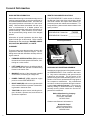
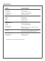
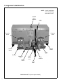
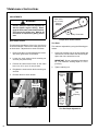
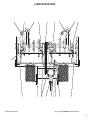
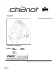
OWNER’S MANUAL
Safety, Assembly, Operating, and Maintenance Instructions
and ILLUSTRATED PARTS MANUAL
PA6685 PERFAERATOR™ Attachment
™
Please Read and Save These Instructions
For Safety, Read All Safety and Operation
Instructions Prior to Operating Machine
Effective Date: 02-06-08
P/N 6600-2
Foreword
Thank you. . .for purchasing a Walker PERFAERATOR™. Every effort has been made to provide
you with the most reliable product on the market, and we are sure you will be among our many satisfied customers. If for any reason this product does not perform to your expectations, please contact us at (970) 221-5614. Every customer is important to us. Your satisfaction is our goal.
Please. . .read this manual thoroughly! This manual is to be used in conjunction with the mower
owner’s manual and the engine manufacturer’s manual for the specific engine on the mower model
you are using. Before you operate your new implement, please read this entire manual. Some of
the information is crucial for proper operation and maintenance of this product - it will help protect
your investment and ensure that the implement performs to your satisfaction. Some of the information is important to your safety and must be read and understood to help prevent possible injury to
the operator or others. If anything in this manual is confusing or hard to understand, please call our
service department, at (970) 221-5614, for clarification before operating or servicing this product.
This manual covers the Model PA6685 PERFAERATOR™ attachment.
All shields and guards must be in place for the proper and safe operation of this aerator.
Where they are shown removed in this manual, it is for illustration purposes only. Do not operate
this product unless all shields and guards are in place.
Specifications given are based on the latest information available at the time this manual was produced.
Walker Mfg. Co. is continually striving to improve the design and performance of its products. We
reserve the right to make changes in specifications and design without thereby incurring any obligation relative to previously manufactured products.
Sincerely,
WALKER MANUFACTURING COMPANY
Bob Walker, President
Table of Contents
Operating Instructions______________10
Owner’s Manual
General Information ________________
2
HIGHLIGHTED INFORMATION _____________
GLOSSARY ____________________________
IDENTIFYING NUMBER LOCATIONS________
SERVICING OF DRIVETRAIN GEARBOX ____
2
2
2
2
Specifications
_______________________ 3
PERFORMANCE ________________________
DIMENSIONS ___________________________
CONSTRUCTION ________________________
DRIVE SYSTEM _________________________
TIRE/WHEEL SIZE _______________________
3
3
3
3
3
Component Identification ___________
4
Safety Instructions __________________
5
BEFORE OPERATING ____________________
OPERATING ____________________________
MAINTENANCE _________________________
SAFETY, CONTROL,
AND INSTRUCTION DECALS ______________
5
6
7
Assembly Instructions
8
______________ 9
SETUP INSTRUCTIONS __________________ 9
Lift Lever Installation ___________________ 9
Installation on Tractor __________________ 9
CONTROL IDENTIFICATION,
LOCATION, AND FUNCTION _____________
Tractor Controls _____________________
Lift Lever ___________________________
Foot Trigger _________________________
STARTING THE MACHINE _______________
ENGAGING THE AERATOR ______________
Normal Operation ____________________
RECOMMENDATIONS FOR AERATING ____
STOPPING THE MACHINE _______________
10
10
10
10
11
11
11
12
12
Maintenance Instructions___________12
LUBRICATION _________________________
Grease Fitting and Oil Point Lubrication__
Gearbox ____________________________
Drive Chain__________________________
Lifting Mechanism ____________________
Camshaft Drive System _______________
PTO U-Joint _________________________
ADJUSTMENTS ________________________
Drive Chain Tension __________________
Tine Ends ___________________________
REPLACING/REPAIRING ________________
Tine Ends ___________________________
REMOVAL ____________________________
END OF SEASON STORAGE _____________
13
13
13
13
13
13
13
14
14
14
15
15
15
15
Illustrated Parts Manual
LUBRICATION POINTS__________________
BODY AND FRAME COMPONENTS _______
CONTROL LINKAGE ____________________
POWER TRANSMISSION COMPONENTS ___
16
18
20
22
Maintenance And Service
Record Sheet ________________________24
Warranty____________________________25
1
General Information
HIGHLIGHTED INFORMATION
IDENTIFYING NUMBER LOCATIONS
Walker Manufacturing recommends that any service
requiring special training or tools be performed by
an authorized Walker Mower Dealer. There are several general practices to be aware of in the area of
safety. Most accidents associated with the operation or maintenance of a Walker product are
caused by disregarding basic safety precautions or
specific warnings. Such accidents, in most cases,
can be prevented by being aware of the dangers
present.
The PERFAERATOR™ serial number is affixed to
the RH side of the inside of the unit housing. Model
and serial numbers are helpful when obtaining replacement parts and maintenance assistance. For
ready reference, please record these numbers in the
space provided.
Information of special importance has been highlighted in bold type in this manual. Refer to Safety
Instructions for the meanings of DANGER, WARNING, CAUTION, IMPORTANT, and NOTE.
PERFAERATOR™ Model No. ______________
PA6685
PERFAERATOR™ Serial No. _______________
Fill In By Purchaser
GLOSSARY
There are many terms that are either unique to this
equipment or that are used as acronyms. The following terms and their definitions will help while using this manual:
•
FORWARD SPEED CONTROL (FSC) controls
the maximum forward speed of the tractor; functioning as a cruise control.
•
LEFT HAND (LH) refers to the left-hand side of
the tractor when the operator is seated facing
forward in the tractor seat.
•
MACHINE consists of the implement installed
on the tractor, functioning as a single unit.
•
POWER TAKE-OFF (PTO) transmits engine
power to run the PERFAERATOR™.
•
RIGHT HAND (RH) refers to the right-hand side
of the machine when the operator is seated facing forward in the tractor seat.
•
TRACTOR is the prime mover, including the engine, drivetrain, operator seat, and controls to
operate the implement.
Serial
Number Plate
Aerator Serial Number Location
SERVICING OF DRIVETRAIN GEARBOX
Detailed servicing and repair of the gearbox used on
the PERFAERATOR™ is not covered in this manual. Only routine maintenance and general service
instructions are provided. For the service of the
gearbox during the limited warranty period, it is important to find a local, authorized servicing agent of
the component manufacturer. Any unauthorized
work done on these components during the warranty period may void the warranty. If you have any
difficulty finding an authorized outlet or obtaining
warranty service, please contact our Service Department for assistance:
Walker Manufacturing Company
5925 E. Harmony Road
Fort Collins, CO 80528
1-970-221-5614
Gearbox manufacturer's information is:
Bondioli & Pavesi
10252 Sycamore Drive
Ashland, VA 23005-8137
1-804-550-2224
2
Specifications
MODEL
PA6685 AERATOR
PERFORMANCE
Aeration Width
41-1/2 in. (105 cm)
Core Spacing
3.63 x 6 in. (9.22 x 15.25 cm)*
Coverage per Hour
70,000 sq. ft. (6500 sq. meters)
Coring Depth
Up to 2.50 in. (6.35 cm)
DIMENSIONS
Weight
390 lb (146 kg)
Height
23-1/4 in. (59 cm)
Width
49-3/4 in. (124 cm)
Length
41-1/2 in. (105 cm)
CONSTRUCTION
Frame
All Welded Unitized Frame
Housing
11 & 14 Gauge Welded Steel
Number of Tines
12
Tine Construction
Machined, High Carbon, Heat-Treated Steel, ThreadMounted (Replaceable)
DRIVE SYSTEM
PTO Drive
Tractor PTO Drive Shaft/2 High-Speed U-Joints, Right
Angle Gearbox, Chain Final Drive to Camshaft
TIRE/WHEEL SIZE
Deck Caster Wheel
Pneumatic 11 x 4.00-5
Roller Wheel
3-7/8 in. (9.84 cm)
* This measurement may vary depending on ground speed
3
Component Identification
NOTE: Control Identification
shown in Operating
Instructions section.
Ground
Speed
Indicator
Lift
Lever
Protective
Cover
Protective
Cover
Plastic
Wheel
Plastic
Wheel
Foot
Trigger
Footrest
Mounting
Tube
Chain
Guard
PTO
Shaft
Cover
PTO
Gearbox
PTO
Shaft
PERFAERATOR™ Top View (Not Installed)
4
Safety Instructions
Pay particular attention to any information labeled
DANGER, WARNING, CAUTION, IMPORTANT,
and NOTE in this manual.
When you see the Safety Alert Symbol (
),
read, understand, and follow the instructions. Failure to comply with safety instructions may result in
personal injury.
The seriousness or degree of importance of each
type of information is defined as follows:
DANGER
The PERFAERATOR™ has been designed with
many safety features to protect the operator from
personal harm or injury. However, it is necessary
for the operator to use safe operating procedures at
all times. Failure to follow safety instructions
contained in this manual may result in personal
injury or damage to equipment or property.
If you have any questions concerning setup,
operation, maintenance, or safety, please
contact your authorized Walker Mower Dealer
or call Walker Manufacturing Company at
(970) 221-5614.
BEFORE OPERATING
An IMMEDIATE hazard that WILL result in
severe personal injury or DEATH, if warning is ignored and proper safety precautions are not taken.
1.
WARNING
A POTENTIAL hazard that COULD result in
severe personal injury or DEATH, if warning is ignored and proper safety precautions are not taken.
CAUTION
Possible hazards or unsafe practices that
MAY result in MODERATE personal injury
or property damage, or machine damage, if
warning is ignored and proper safety precautions are not taken.
IMPORTANT: Identifies mechanical information demanding special attention, since it deals with the possibility of damaging a part or parts of the machine.
Walker Manufacturing Company
5925 East Harmony Road
Fort Collins, CO 80528
2.
Never allow children to operate or give rides
on the machine. Do not allow adults to operate without proper instruction.
3.
Do not allow anyone other than the operator on
the machine.
4.
Keep everyone, especially children and pets, a
safe distance away from the area being aerated.
Do not operate with bystanders in the area.
5.
Do not operate the machine wearing sneakers,
tennis shoes, or similar lightweight footwear.
Wear substantial protective footwear that
will improve footing on slippery surfaces.
6.
Ground cover or leaves can sometimes hide objects that might cause damage to the aerator.
Clear the area of objects and mark all sprinkler
heads and/or utility box covers.
7.
Do not wear loose fitting clothing that could get
caught in moving parts. Always wear adequate protective clothing including long
pants. Wearing safety glasses, safety shoes,
and a helmet is advisable and required by some
local ordinances and insurance regulations.
NOTE: Identifies information worthy of special
attention.
Walker Manufacturing cannot predict every potentially dangerous situation. Therefore, items labeled
as such in this manual do not cover all conceivable
situations. Any person using procedures, tools, or
control techniques not recommended by Walker
Manufacturing must take full responsibility for safety.
Read and understand the contents of this
OWNER'S MANUAL before operating the
machine. Become thoroughly familiar with all
controls and how to stop the machine and disengage the controls quickly. Replacement
Owner's Manuals are available by sending the
Model and Serial Number to:
5
Safety Instructions
8.
9.
Prolonged exposure to loud noise can cause
impairment or loss of hearing. Operator hearing protection is recommended. Wear a suitable hearing protective device, such as
earmuffs or earplugs.
OPERATING
Keep all protective shields and safety devices in place. If a protective shield, safety device,
or decal is damaged, unusable, or missing, repair or replace it before operating the machine.
1.
Operate the machine only in daylight or in good
artificial light with good visibility of areas being
aerated.
2.
Sit on the seat when starting the engine and operating the machine. Keep feet on footrests at
all times when the tractor is moving and/or the
implement is operating.
3.
An inexperienced operator should learn to
steer (maneuver) the tractor with a slow engine speed before attempting any operating.
Be aware that, with the front mounted implement
configuration, the back of the machine swings to
the outside during turns.
4.
Remember, for an emergency stop, the forward
motion of the tractor can always be stopped by
pulling the Forward Speed Control (FSC) into
the NEUTRAL-PARK position.
5.
Disengage the PTO clutch and put the FSC in
the NEUTRAL-PARK position before starting
the engine (an ignition interlock switch normally
prevents starting of the tractor if these controls
are in the OPERATING position).
6.
Do not run the engine in a confined area
without adequate ventilation. Exhaust fumes
are hazardous and can be deadly.
7.
Do not carry passengers - maximum seating
capacity is one (1) person.
8.
Make sure the tines are clear of debris before
engaging the PTO clutch.
9.
Be careful never to allow anyone in front of the
implement.
10. Be sure any interlock switches are functioning correctly so the engine cannot be started
unless the Forward Speed Control lever is in the
NEUTRAL position and the PTO clutch is in the
DISENGAGED position. Also, the engine
should stop if the operator lifts off the seat with
either the Forward Speed Control (FSC) out of
the NEUTRAL-PARK position or the PTO clutch
in the ENGAGED position.
NOTE: There is a 1 to 1-1/2 second time delay
function on the seat switch to avoid engine
power interruption when driving over bumps.
11. Never attempt to make any adjustments
while the engine is running, except where
specifically instructed to do so.
NOTE: Refer to the Walker Rider Lawnmowers
OWNER’S MANUAL for safety instructions for operating the tractor.
12. Handle gasoline or diesel fuel with care.
Gasoline is highly flammable and its vapors are
explosive:
a.
Use an approved fuel container.
b.
Never add fuel to a running engine or hot
engine (allow hot engine to cool several
minutes).
c.
Keep matches, cigarettes, cigars, pipes,
open flames, or sparks away from the fuel
tank and fuel container.
d.
e.
Always fill the fuel tank outdoors using care.
Fill to about one inch from the top of the tank.
Use a funnel or spout to prevent spilling.
Replace the machine fuel cap and container
cap securely and clean up any spilled fuel
before starting the engine.
WARNING
The engine exhaust from this product
contains chemicals known to the State of
California to cause cancer, birth defects
or other reproductive harm.
6
10. Clear area of loose objects and all children.
Flag sprinkler heads and other hidden obstacles. Walk the entire area before aerating for
possible holes.
11. Avoid sudden starts or stops. Before backing
the machine up, disengage the PTO, retract
tines and look to the rear to be sure no one is
behind the machine. Watch carefully for traffic
when crossing or working near roadways.
Safety Instructions
12. Disengage the PTO clutch when transporting
the machine.
13. Do not operate across the face of slopes. Use
extreme caution when changing direction on
slopes.
MAINTENANCE
NOTE: Refer to the Walker Rider Lawnmowers
OWNER’S MANUAL for proper tractor maintenance procedures.
1.
To prevent accidental starting of the engine
when servicing or adjusting the machine, remove the key from the ignition switch and disconnect the fuel solenoid wire [diesel engines]
or the spark plug wire(s) [gasoline engines].
2.
To reduce fire hazards, keep the engine free of
grass, leaves, excessive grease, and dirt.
3.
Keep all nuts, bolts, and screws tight to ensure
the machine is in a safe, working condition.
4.
Perform only maintenance instructions described in this manual. Unauthorized maintenance operations or machine modifications
may result in unsafe operating conditions.
5.
If the engine must be running to perform a maintenance adjustment, keep hands, feet, and
clothing away from moving parts. Do not
wear jewelry or loose clothing.
6.
Always use proper engine service manuals
when working on the engine. Unauthorized
maintenance operations or modifications to the
engine may result in unsafe operating conditions.
17. If the implement strikes a solid object or the machine begins to vibrate abnormally, immediately disengage the PTO clutch, stop the
engine, and wait for all moving parts to stop.
Disconnect the fuel solenoid wire [diesel engines] or the spark plug wire(s) [gasoline engines] to prevent accidental starting.
Thoroughly inspect the implement and repair
any damage before restarting the engine and
operating the machine. Make sure implement
components are in good condition and all bolts
are tight.
7.
Altering the machine in any manner which adversely affects its operation, performance, durability, or use will VOID the warranty and may
cause hazardous conditions.
8.
Never attempt to disconnect any safety devices
or defeat the purpose of these safety devices.
9.
Do not change the engine governor settings or
overspeed the engine. The governor has been
factory-set for maximum-safe engine operating
speed.
18. Do not touch the engine or muffler while the
engine is running or immediately after stopping the engine. These areas may be hot
enough to cause serious burns.
10. Use genuine factory replacement parts.
Substitute parts may result in product malfunction and possible injury to the operator and/or
others.
19. When leaving the machine unattended, disengage the PTO clutch, stop the engine, and remove the ignition key.
IMPORTANT: Keep all applicable manuals
immediately accessible to anyone who may
operate or service this machine.
14. Never adjust tine depth with the engine running. Before adjusting tines or servicing, disengage the PTO clutch, stop the engine, and
remove the ignition key. Wait for all movement
to stop before getting off the seat.
NOTE: The PTO brake should normally stop
drive line rotation within 5 seconds of disengaging the PTO clutch.
15. Do not operate the aerator with the covers open.
16. If the aerator tines do not move when the PTO
is engaged:
a. Disengage the PTO clutch, stop the engine,
and remove the ignition key before leaving
the seat.
b. LOOK to make sure PTO shaft and the tine
movement has stopped before servicing
any area of the machine.
c. Disconnect the fuel solenoid wire [diesel engines] or spark plug wire(s) [gasoline engines].
7
Safety Instructions
SAFETY, CONTROL, AND INSTRUCTION DECALS
Safety, Control, and Instruction Decals are installed on the machine; if any are missing, illegible, or
damaged, a replacement should be ordered and installed before putting the machine into operation. The
Decal Part Number is listed below and in the Parts Section; the Decal Location is shown in the Parts Section.
Speed Indicator (Walker P/N 6681-13)
Door Cover (Walker P/N 6682-9)
PTO Shield (Walker P/N 7822)
Operator Decal (Walker P/N 6682-14)
8
Assembly Instructions
SETUP INSTRUCTIONS
The PERFAERATOR™ is shipped partially assembled. After uncrating, initial setup is required.
NOTE: During the process of unpacking, any damaged or missing parts should be noted and reported
to the delivering carrier immediately (put in writing
within 15 days). The carrier will provide directions
for proceeding with a claim to receive compensation
for damage.
Mounting
Tubes
Lift Lever Installation
The lift lever for the camshaft assembly position is
partially assembled. Stand the lift lever upright and
attach the remaining hardware.
Attach Aerator to Tractor
3.
Engage the aerator frame tube sockets on the
tractor support arms. Slide the implement
hitch onto the support arms approximately 3 in.
(76 mm).
Lift Lever
Only use PTO U-Joint
Tube P/N 7275-15
(9.06 in. OAL)
Connect Driveline Coupler to Tractor PTO
4.
Install Lift Lever Handle
(stand upright and insert hardware)
Installation on Tractor
1.
Remove the mower deck from the tractor if necessary.
Refer to the appropriate Tractor
Owner's Manual.
2.
Lightly grease each tractor support arm (2) on
the tractor.
Connect the aerator driveline to the tractor PTO
shaft by sliding back the locking collar on the
yoke, then push the yoke over the PTO shaft
until the locking collar snaps back fully. Make
sure the driveline is well secured at both ends.
DANGER
This shaft turns at very high RPM. If the
collar is not locked to the PTO shaft at the
tractor end, or if the yoke at the aerator
end is not secured properly, the driveline
can fly loose with great force capable of
causing serious injury or death.
5.
Install the hitch pin through the hole on the end
of each support arm to lock the hitch in place.
Two (2) hitch pins are included in the owner’s
packet of materials.
9
Operating Instructions
CONTROL IDENTIFICATION, LOCATION, AND
FUNCTION
CAUTION
Before operating the aerator, become familiar with the location and function of
all operator controls. Knowing the location, function, and operation of these
controls is important for safe and efficient operation of the aerator.
Tractor Controls
Lift Lever
The lift lever is located to the right of the operator up
from the right footrest. The lever is used to raise and
lower the camshaft assembly. Moving the lift handle
forward lowers the aerator drive assembly; moving
it backward raises the aerator drive assembly.
Foot Trigger
The foot trigger is located on the right footrest. The
foot trigger and the lift lever are used together to
raise and lower the aerator drive assembly. Pull the
handle back, press the foot trigger, and hold on to
the lift handle while letting it move forward to
lower the aerator drive assembly.
Refer to the appropriate Tractor Owner's Manual for
complete information about tractor operating controls.
Lift Lever
Foot Trigger
Operating Controls
10
Operating Instructions
STARTING THE MACHINE
CAUTION
ALWAYS disengage the PTO clutch and
put the FSC in the NEUTRAL-PARK position before starting the engine.
Normal Operation
IMPORTANT: The aerator has a natural driving motion when engaged, so the speed of the tractor is
critical to ensure proper aeration and longevity of
aerator components.
1.
Adjust ground speed to properly position tines
as shown.
IMPORTANT: If ground speed is too fast, the
retractor plates will swing away from the front,
causing a shallow plugged hole.
Refer to the appropriate Tractor Owner’s Manual for
tractor starting and operating procedures.
ENGAGING THE AERATOR
IMPORTANT: If ground speed is too slow, the
retractor plates will swing forward and make
constant contact with the front frame, resulting
in excessive wear of tines and retractor plates.
Refer to the appropriate Tractor Owner’s Manual for
tractor starting and operating procedures.
1.
Release the tines into the operating position by
pushing on the foot trigger and using the lift
lever to lower the tines.
2.
Set the engine throttle at full speed.
3.
Begin driving the tractor forward slowly.
4.
Pull the PTO clutch lever UP to engage the
aerator.
Adjust Ground Speed As
Indicated By Decal
Lubricate Grease
Fitting On Cam
Rings (12 Fittings)
Every 4 Hours
CAUTION
A safety interlock switch (seat switch) will
cause the engine to stop if the FSC is out
of the NEUTRAL-PARK position and the
operator is not in the seat. The function
of this switch should be checked by the
operator raising off the seat with the tractor moving forward (allow 1 to 1-1/2 seconds off the seat for the time delay
function); the engine should stop. If the
safety system is not working, it should be
repaired or replaced before operating the
mower. DO NOT disconnect the safety
switches; they are for the operator's protection.
IMPORTANT: DO NOT engage the PTO clutch
when transporting the machine. DO NOT
engage the PTO clutch with the PTO shaft
disconnected (the aerator removed from the
tractor).
2.
If an obstacle is encountered during operation
(sprinkler head, sidewalk, etc.), the PTO can
be disengaged and reengaged after passing
obstacle.
IMPORTANT: Minimum turning radius is 10
feet (3.05 m). Turning too tight can result in
damage to the turf and the aerator.
CAUTION
DO NOT pull the retractor lever while
operating.
11
Operating Instructions
RECOMMENDATIONS FOR AERATING
STOPPING THE MACHINE
For best results the ground must have a sufficient
amount of moisture to allow the tines maximum penetration.
1.
Disengage the PTO clutch.
2.
IMPORTANT: Operate the engine at full speed
when operating the aerator, to allow the engine to
produce full horsepower and to increase efficiency
of the engine cooling system.
Pull the steering levers to the NEUTRAL
position and then move the FSC lever
backward to the NEUTRAL-PARK position.
3.
Slow the engine to idle; put the throttle in the
IDLE position.
•
Do not drive the mower backwards with the
aerator in the down position--it may cause
severe turf damage.
4.
Retract the tines into the transport position
using the lift lever.
•
Driving the tractor too slow may cause turf
damage.
•
Driving the tractor too fast will make aeration
holes appear less frequently and too shallow
(short plugs) may do a less than desirable job.
•
Do not engage the PTO with the drive
assembly in the transport position.
WARNING
A brake stops the machine from freewheeling within five (5) seconds after disengaging the PTO clutch. If the brake system malfunctions and the machine does
not stop within five (5) seconds, the brake
should be adjusted or repaired before operating the machine. Refer to the appropriate Tractor Owner’s Manual for
adjustment procedures.
5.
Turn the ignition switch OFF.
WARNING
Remove the key from the ignition switch
when leaving the machine unattended.
This will prevent children and inexperienced operators from starting the engine.
6.
Engage the parking brake.
IMPORTANT: The hydrostatic transmissions
lock to prevent the machine from rolling freely
with the engine stopped. However, if the
machine is parked on a slope, it is necessary to
ENGAGE the parking BRAKE to prevent the
machine from creeping. This is due to a small
amount of slippage in the hydrostatic transmissions, especially when transmission fluid is
warm.
12
Maintenance Instructions
LUBRICATION
WARNING
DO NOT attempt to lubricate the machine
with the tractor engine running. Disengage the PTO clutch, shut off the machine, and remove the ignition key.
Grease Fitting and Oil Point Lubrication
Lubricate the grease fittings and oil points after every 8 hours of operation (or as recommended below). Use Almagard® #3752 (Walker P/N 6685-7)
grease for grease fittings and light machine oil
(SAE 10) to lubricate oil points.
2.
Apply oil to the drive chain.
3.
Adjust the chain if necessary. Refer to ADJUSTMENTS of Drive Chain Tension in this
section.
4.
Reinstall chain guard cover by reversing the removal procedure.
Lifting Mechanism
Lubricate the grease fittings (4) across the lifting
mechanism attached to the frame every 25 hours.
Use SAE general purpose lithium or molybdenum
base grease.
Gearbox
The gearbox is permanently lubricated (oil filled) and
sealed requiring no scheduled lubrication. However, the gearbox oil seal(s) should be checked every 25 hours for indication of an oil leak. If gearbox
oil is changed, fill with 15 oz. (44 cl) of 80W-90 gear
oil. Do not overfill.
Camshaft
Drive
Drive Chain
Lubricate the drive chain every 8 hours. A light
penetrating oil or special purpose chain oil is recommended. Lubricate the drive chain as follows:
Lifting
Mechanism
Lubricating Lift Mechanism and Camshaft Drive
1.
Remove the three (3) bolts fastening the
removable chain guard cover to the frame.
Camshaft Drive System
Lubricate the grease fittings (16) on the camshaft
drive system every 4 hours. Use Almagard® #3752
lubricant (Walker P/N 6685-7).
The bearings at each end and attached to the retractor plate arms are sealed and should be greased every 100 hours of operation. Use SAE general
purpose lithium or molybdenum base grease.
PTO U-Joint
Lubricate the grease fitting for the PTO U-Joint every 8 hours with SAE general purpose lithium or
molybdenum base grease.
The PTO U-Joint is accessed by removing the gearbox cover.
Remove Chain Guard Cover
13
Maintenance Instructions
ADJUSTMENTS
1/4 to 1/2 in.
(6 to 13 mm)
Slack at
Midspan
WARNING
DO NOT attempt to make any adjustments
with the tractor engine running. Disengage the PTO clutch, shut off the machine,
and remove the ignition key. Wait for all
movement to stop before getting off the
seat.
Chain Idler
Proper Drive Chain Tension
Drive Chain Tension
Tine Ends
The drive chain should have 1/4 to 1/2 in. (6 to 13 mm)
of slack at midspan. Remove the chain guard cover
to check slack. Adjust the drive chain as follows:
Tine ends are adjustable by using the following procedure:
1.
Remove the three (3) bolts fastening the removable chain guard cover to the frame.
1.
2.
Loosen the chain tension block mounting nut
and bolt (see photo below).
3.
Position the chain tension block so the chain
has 1/4 to 1/2 in. (6 to 13 mm) of slack.
4.
Retighten the chain tension block mounting nut
and bolt.
5.
Recheck the drive chain tension.
Loosen the retaining nut on the tine thread and
unscrew tine end to achieve the desired depth.
Open side of tine should be to rear.
IMPORTANT: Do not unscrew the tine ends too
far. The maximum aerating depth is 2-1/2 in.
(6.35 cm).
2.
Tighten retaining nut.
Retaining
Nut
Tension
Block Nut
Tine
Opening
Ref. Chain
Guard
Tine
Opening
to Face
Rear of
Unit
Drive Chain Adjustment
14
Tine End Depth Adjustment
Maintenance Instructions
REPLACING/REPAIRING
CAUTION
REMOVAL
1.
ALWAYS use genuine factory replacement
parts. Substitute parts CAN result in product malfunction and possible injury to the
operator and/or others.
WARNING
DO NOT attempt to remove the aerator
from the tractor with the engine running.
Disengage the PTO clutch, shut off the
machine, and remove the ignition key.
Wait for all movement to stop before getting off the seat.
WARNING
DO NOT attempt to make any replacements or repairs with the tractor engine
running. Disengage the PTO clutch, shut
off the machine, and remove the ignition
key. Wait for all movement to stop before
getting off the seat.
Park the tractor on a level surface with the tines
in the up position.
2.
Remove the hitch pins from the ends of the support arms.
3.
Slide the PTO shaft out of the PTO coupler
while sliding the aerator off the tractor support
arms.
Tine Ends
END OF SEASON STORAGE
Tine ends are replaceable by using the following
procedure:
1.
Clean the aerator thoroughly.
1.
Loosen the retaining nut on the tine thread and
unscrew tine end.
2.
Repainting all parts where paint has worn.
2.
Install new tine end by reversing the removal
procedure. Open side of tine should be to rear.
NOTE: Rustproofing or painting every year will
prolong the life of the aerator components and
moving parts.
3.
When the aerator is dry, lubricate all moving
parts. Apply lubricant liberally to all surfaces to
protect against rust.
4.
Store the aerator in a dry place.
15
LUBRICATION POINTS
ITEM
NO.
LOCATION
LUBRICATION
TYPE
NO.
PLACES
ITEM
NO.
LOCATION
6
7
8
9
10
11
Actuator Rod Pivots
Deck Support Arm Socket
Universal Joint Shaft Assembly
Actuator Link Latch
Foot Trigger Pivot
Engage Lever Pivot
LUBRICATION
TYPE
NO.
PLACES
Lubrication Points
1
2
3
4
5
Deck Caster Wheel Fork Pivot
Deck Caster Wheel Bearing
Rod Bearing Bushing
Drive Chain
Eccentric Assembly Tine
Grease
Grease
Grease
Oil*
Grease**
2
2
4
1
12
*
Grease
Grease
Grease*
Oil
Oil
Grease
4
2
1
1
1
1
Grease every eight (8) hours.
** Grease every four (4) hours using Almagard #3752 lubricant
(Walker P/N 6685-7).
NOTE: The gearbox is permanently lubricated (oil filled)
and sealed requiring no scheduled lubrication.
However, the gearbox oil seal(s) should be
checked every 25 hours for indication of an oil
leak.
Use only genuine Walker® replacement parts.
16
Effective Date 02-06-08
LUBRICATION POINTS
2
3
1
3
4
3
1
7
11
2
3
5
6
Effective Date 02-06-08
7
6
8
9
10
6
Use only genuine Walker® replacement parts.
17
BODY AND FRAME COMPONENTS
ITEM
NO.
PART
NO.
DESCRIPTION
NO.
REQ’D
Body And Frame Components
1
6682-3
2
6681-10
3
4
5
6
7
8
9
10
6682-9
7504-4
5856
6681-13
6682-14
7504-3
5803
6681-11
11
12
13
6682-2
5103-4
6683-1
14
15
8746
6684-9
16
17
18
19
20
21
7822
8790
6681-12
6683-5
5830-3
6682
22
23
24
25
26
6715
6682-13
5800
5830
6682-0
Front Cover
(Includes Item # 11)
Rear Cover, RH
(Includes Items # 3, 4, 5 & 17)
Decal, Cover
Hinge (15-1/2")
Decal, Made In USA
Decal, Ground Speed Indicator
Decal, Perfaerator Oper.
Hinge (27")
Decal, Walker Mfg. Logo
Rear Cover, LH
(Includes Items # 3, 7, 8, 9 & 17)
Decal, Perfaerator Oval
Pivot Bushing (3/8 ID)
Shaft Guard
(Includes Items # 12 & 14)
Decal, U-Joint Tube
Transport Latch Release
(Includes Item # 16)
Decal, PTO Shield/Danger
Rubber Cushion Strip
Chain Guard
Toe Guard, Bolt On
Grease Fitting (45 Deg.)
Perfaerator Carrier Frame
(Includes Item # 24)
Roller Wheel (3-7/8)
Axle Spacer
Decal, Walker Mower
Grease Fitting
Upright Base
6681-23
6681-14
6681-22
6681-16
6681-25
6681-17
6681-21
6681-19
Plastic Cap, Black
Arrow, Ground Speed Indicator
Spacer Tube (2")
Bushing (5/16 x 3/8 x 3/4)
Actuator Rod Mount
Torsion Spring (.435 ID)
Spacer (.475)
Ground Speed Indicator Rod
Use only genuine Walker® replacement parts.
18
PART
NO.
DESCRIPTION
NO.
REQ’D
Caster Wheel Components
1
1
2
1
1
1
1
1
1
1
1
2
1
1
1
1
4
1
2
4
1
2
2
2
2
1
Ground Speed Indicator Components
27
28
29
30
31
32
33
34
ITEM
NO.
35
36
37
38
39
8766
8768-2
8037
8037-2
8768
40
41
42
43
44
45
8767
8765-10
8769-7
8769-6
8769-5
8769-8
Axle Nut (3/4-16)
Seal, Reverse Lip
Bearing Cone (3/4 ID)
Bearing Race
Caster Wheel, Pneumatic (11 x 4.00-5)
(Includes Items # 20 & 39)
Axle, Caster Wheel (5-1/8)
Caster Wheel Fork
Seal
Bearing Cone (1" ID)
Bearing Cup (2 x 1-5/8)
Dust Cap, Deck Caster
2
4
4
4
2
2
2
2
4
4
2
Fasteners
F004
F005
F009
F013
F014
F023
F029
F061
F116
F128
F140
F218
F246
F344
F347
F348
F355
F366
F389
F438
1/4-20 Keps Nut
1/4-20 ESNA Nut
5/16-18 Whiz Locknut
3/8-16 Whiz Locknut
3/8-16 ESNA Nut
10-24 ESNA Nut
1/4-20 x 1/2 Hex Bolt
1/4 Star Lock Washer
1/4-20 x 1-1/4 Hex Bolt
10-24 x 3/8 PTHMS
7/16-14 x 1 Hex Bolt
7/16 Split Lock Washer
1/4-20 x 1/2 PTHMS
3/4-16 Slotted Hex Nut
3/4 SAE Washer
1/8 x 1-1/2 Cotter Pin
3/8-16 x 4 Hex Bolt
5/16-18 x 3 Carriage Bolt
3/8-16 x 2-3/4 Hex Bolt
5/16-18 x 2-3/4 Hex Bolt
10
14
6
2
1
22
11
3
2
22
4
4
12
2
2
2
1
2
2
2
1
1
1
3
1
1
2
1
Effective Date 02-06-08
BODY AND FRAME COMPONENTS
3
4
2
5
F246
6
7
1
8
9
3
F128
10
27
11
F009
28
F023
29
30
F355
32
31
14
12
15
34
33
F116
13
12
30
F014
30
17
F029
F005
24
F029
F061
19
16
17
F061
F004 F029
F389
18
F438
F348
20
45
F344
F347
20
43
44
26
21
44
43
42
41
25
F005
17
F013
F140
F218
F009
22
25
23
F218
F140
F366
24
40
36
37
24
38
38
F009
37
36
35
39
20
Effective Date 02-06-08
Use only genuine Walker® replacement parts.
19
CONTROL LINKAGE
ITEM
NO.
PART
NO.
DESCRIPTION
NO.
REQ’D
Control Linkage
1
2
5850-3
6684
3
4
5
6
7
8
9
10
11
12
13
14
15
16
17
18
19
6684-1
6684-3
6684-4
7222
5281-2
6684-5
5830
6686-5
6686-3
5214-2
6686
6685-8
6685-7
6685-5
6681-8
6685-4
6684-2
20
8788
6685-6
6681-2
6685-2
24
25
26
27
28
29
30
31
32
6686-6
6686-1
6685-15
6685-9
6685-16
6681-15
6686-4
6686-7
6681
33
6681-1
6681-7
Handle Grip, Foam (3-1/4)
Transport Lever
(Includes Item # 1)
Transport Lever End
Release Latch
Link, Lever Latch
Extension Spring (1/4 x 3)
Clevis Pin (5/16 x 7/8)
Actuator Link
Grease Fitting
Actuator Cross Shaft Assembly
Actuator Cross Shaft Mount
Ball Joint (5/16-24) Nylon Lined
Transport Pivot Tie Rod
Cam Alignment Plate
Grease, Almagard #3752
Machined Cam
Cam Bearing
Tine Casting
Pivot, Transport Lever
(Includes Items # 9 & 20)
Rubber Bumper (Self-Adhesive Mount)
Cartridge Bearing
Tine Crank Shaft
Tine Crank Sprocket
(Includes Items # F171 & F231)
Retractor Plate, LH
Retractor Plate Lift Bracket, LH
Spacer, Short
Hanger Rod
Hanger Rod Bearing W/Bushing
Actuator Block
Retractor Plate Lift Bracket, RH
Retractor Plate, RH
Tine Crank Assembly
(Includes Items # 23, 25 & 30)
Perfaerator Tip
Solid Spike Tine Tip
Use only genuine Walker® replacement parts.
20
PART
NO.
DESCRIPTION
NO.
REQ’D
Fasteners
1
1
F005
F007
F009
F010
F013
F020
F023
F038
F050
F054
F093
F103
F111
F116
F171
F211
F261
F312
F404
F417
F460
1
1
1
1
2
2
9
1
2
8
4
12
*
12
12
12
1
1
Tine Crank Assembly Components
21
22
23
ITEM
NO.
3
1
1
*
1/4-20 ESNA Nut
5/16-18 Jam Nut
5/16-18 Whiz Locknut
5/16-24 ESNA Nut
3/8-16 Whiz Locknut
5/16-18 ESNA Nut
10-24 ESNA Nut
3/8-16 x 1 Hex Bolt
1/4 SAE Washer
AN960616 Washer
5/16-18 x 1 Hex Bolt
10-24 x 2 PTHMS
1/8 x 3/4 Cotter Pin
1/4-20 x 1-1/4 Hex Bolt
5/16-18 x 3/8 Set Screw
1/4-20 x 7/8 Hex Bolt
AN960616L Washer
3/8 x 3/8 Shoulder Bolt
5/8-18 Jam Nut
3/8-16 x 1-1/4 Carriage Bolt
1/4 x 1 Woodruff Key
6
8
2
8
6
4
2
4
4
2
6
2
3
4
2
2
2
2
8
2
1
Grease every eight (8) hours using Almagard #3752 lubricant
(Walker P/N 6685-7).
** Service Part Only.
1
2
3
4
4
1
2
1
**
12
**
Effective Date 02-06-08
CONTROL LINKAGE
1
2
F211
F093
9
20
F005
3
4
F009
F093
F054
F261
F009
19
9
21
26
F111
F261
F312
9
7
9
8
5
8
23
6
9
27
F116
F020
9
28
F312
F054
F111
11
F020
F171
F460
22
Refer to
Body and Frame
Components
10
22
F404
28
30
F093
27
26
9
28
31
F007
F007
27
F404
25
F116
32
9
F116
30
F103
29
F050
F005
12 F010
9
F404
28
27
F010
26
F404
F404
F116
11
13
21
F020
12
25
F050
F005
F404
F050
F038
24
F023
F005
F404
F404
18
33
F050
F005
F013
17
16
14
F013
F417
F013
15
F038
Refer to
Body and Frame
Components
Effective Date 02-06-08
Use only genuine Walker® replacement parts.
21
POWER TRANSMISSION COMPONENTS
ITEM
NO.
PART
NO.
DESCRIPTION
NO.
REQ’D
6683-2
2
3
4
5
6
6875
6683-6
6685
6685-14
6685-3
U-Joint Shaft
(Includes Items # 2, F076, F149 & F318)
Decal, PTO Alignment Arrow
PTO Gearbox/Shear
Perfaerator Chain (#50 x 88 Links)
Gearbox Sprocket, Shear
Idler Sprocket
Use only genuine Walker® replacement parts.
22
PART
NO.
DESCRIPTION
NO.
REQ’D
Fasteners
Power Transmission Components
1
ITEM
NO.
1
1
1
1
1
1
F004
F013
F041
F051
F076
F123
F149
F290
F318
F383
1/4-20 Keps Nut
3/8-16 Whiz Locknut
3/8-16 x 1-3/4 Hex Bolt
3/8 SAE Washer
3/8-16 x 5/8 SQH Set Screw
1" External Snap Ring
1/4 x 1/4 x 1-1/2 Key
3/8-16 x 5 Hex Bolt
3/8-16 x 3/4 SQH Set Screw
1/4-20 x 2 Shear Bolt Grade 2
1
5
1
2
1
1
1
4
1
1
Effective Date 02-06-08
POWER TRANSMISSION COMPONENTS
F290
F076
1
2
F318
Refer to
Body and Frame
Components
F149
3
4
F383
5
F013 F051 6
F051
F123
F041
F004
Refer to
Control Linkage
Refer to
Body and Frame
Components
F013
Effective Date 02-06-08
Use only genuine Walker® replacement parts.
23
MAINTENANCE AND SERVICE RECORD SHEET
DATE
SERVICE
ITEM
ENGINE
HOURS
______________________________________________________________________________________________________________
______________________________________________________________________________________________________________
______________________________________________________________________________________________________________
______________________________________________________________________________________________________________
______________________________________________________________________________________________________________
______________________________________________________________________________________________________________
______________________________________________________________________________________________________________
______________________________________________________________________________________________________________
______________________________________________________________________________________________________________
______________________________________________________________________________________________________________
______________________________________________________________________________________________________________
______________________________________________________________________________________________________________
______________________________________________________________________________________________________________
______________________________________________________________________________________________________________
______________________________________________________________________________________________________________
______________________________________________________________________________________________________________
______________________________________________________________________________________________________________
______________________________________________________________________________________________________________
______________________________________________________________________________________________________________
______________________________________________________________________________________________________________
______________________________________________________________________________________________________________
______________________________________________________________________________________________________________
______________________________________________________________________________________________________________
______________________________________________________________________________________________________________
______________________________________________________________________________________________________________
______________________________________________________________________________________________________________
______________________________________________________________________________________________________________
______________________________________________________________________________________________________________
______________________________________________________________________________________________________________
______________________________________________________________________________________________________________
______________________________________________________________________________________________________________
______________________________________________________________________________________________________________
______________________________________________________________________________________________________________
______________________________________________________________________________________________________________
Use only genuine Walker® replacement parts.
24
Effective Date 02-06-08
LIMITED WARRANTY
FOR
WALKER
COMMERCIAL RIDER MOWER
1.
WHAT THIS WARRANTY COVERS, AND FOR HOW LONG:
Walker Manufacturing company will, at its option, repair or replace, without charge, any part covered by this warranty which
is found to be defective in material and/or workmanship within one (1) year* after date of sale to the original retail purchaser unless the product is used for rental purposes, in which case this warranty is limited to ninety (90) days. At
Walker’s request, customer will make the defective part available for inspection by Walker and/or return the defective part
to Walker, transportation charges prepaid. All parts and components of the Walker Mower are covered by this warranty
except the following components which are warranted separately by their respective manufacturers:
Bondioli & Pavesi
Rock Solid™ (A Division of Industrial Machine Specialties, Inc.)
The available warranties covering these items are furnished with each mower. Walker does not assume any warranty obligation, liability or modification for these items, which are covered exclusively by the stated warranty of the respective manufacturers noted above.
2.
3.
WHAT THIS WARRANTY DOES NOT COVER:
A.
This warranty does not cover defects caused by depreciation or damage caused by normal wear, accidents, improper
maintenance, improper use or abuse of the product, alterations, or failure to follow the instructions contained in the
Owner’s Manual for operation and maintenance.
B.
The customer shall pay any charges for making service calls and/or for transporting the mower to and from the place
where the inspection and/or warranty work is performed.
HOW TO OBTAIN SERVICE UNDER THIS WARRANTY:
Warranty service can be arranged by contacting the dealer where you purchased the mower or by contacting Walker Manufacturing Company, 5925 East Harmony Road, Ft. Collins, CO 80528. Proof of the date of purchase may be required to
verify warranty coverage.
4.
WARRANTY LIMITATION:
A.
THERE IS NO OTHER EXPRESS WARRANTY. ANY WARRANTY THAT MAY BE IMPLIED FROM THIS
PURCHASE INCLUDING MERCHANTABILITY AND FITNESS FOR A PARTICULAR PURPOSE IS HEREBY
LIMITED TO THE DURATION OF THIS WARRANTY AND TO THE EXTENT PERMITTED BY LAW ANY AND ALL
IMPLIED WARRANTIES ARE EXCLUDED. Some states do not allow limitations on how long an implied warranty
lasts, so the above limitations may not apply to you.
B.
WALKER WILL NOT BE LIABLE FOR ANY INCIDENTAL, CONSEQUENTIAL, OR SPECIAL DAMAGES AND/OR
EXPENSES IN CONNECTION WITH THE PURCHASE OR USE OF THE MOWER. Some states do not allow the
exclusion or limitation of incidental or consequential damages, so the above limitation(s) or exclusion(s) may not
apply to you.
C.
Only the warranty expressed in this limited warranty shall apply and no dealer, distributor, or individual is authorized
to amend, modify, or extend this warranty in any way. Accordingly, additional statements such as dealer advertising
or presentations, whether oral or written, do not constitute warranties by Walker, and should not be relied upon.
D.
This warranty gives you specific legal rights, and you may also have other rights which vary from state to state.
25
TM
WALKER MFG. CO. • 5925 E. HARMONY ROAD, FORT COLLINS, CO 80528 • (970) 221-5614
FORM NO. 020608
PRINTED IN USA
www.walkermowers.com
©2008 WALKER MFG. CO