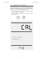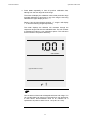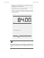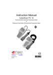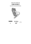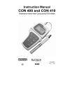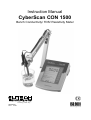
1
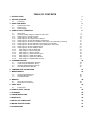
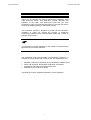
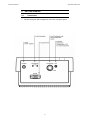
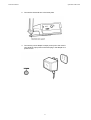
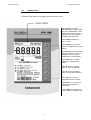
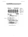
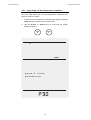
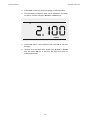
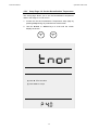
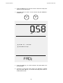
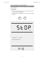
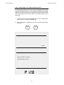
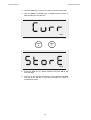
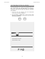
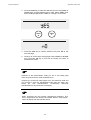
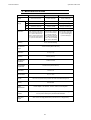
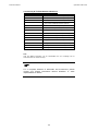
Instruction Manual CyberScan CON 1500 Bench Conductivity/ TDS/ Resistivity Meter Technology Made Easy ... 68X292335 Rev 1 01/04 PREFACE Thank you for selecting the Eutech Instruments CyberScan CON 1500 bench meter. The instruction manual serves to explain the use of the CyberScan CON 1500 bench meter as a step-by-step operational guide to help you familiarise with the meter’s features and functions. It is structured sequentially with illustration of diagrams that explains the various functions and setup menus available. This manual is written to cover as many anticipated applications and uses of the CyberScan CON 1500 bench meter as possible. If there are doubts in the use of the meter, please do not hesitate to contact the nearest Eutech Instruments’ Authorised Distributors or call us at (65) 6778-6876 for Eutech Instruments’ Customer Service Dept. for assistance. Kindly remember to complete the warranty card and mail it back to your Authorised Distributors or Eutech Instruments Pte Ltd. Eutech Instruments reserve the rights to change, make improvement and modify specifications without prior notice and cannot accept any responsibility for damage or malfunction to the instrument caused by improper use. Copyright © 2003 Eutech Instruments Pte. Ltd. All rights reserved. Rev 1, 01/04. TABLE OF CONTENTS 1. INTRODUCTION 1 2. GETTING STARTED 2 2.1. Connectors 3. USING THE METER 3.1. 3.2. 3.3. Conductivity Probes Display/ Keys Screen Display 4. CONDUCTIVITY OPERATION 4.1. 4.2. 4.2.1 4.2.2 4.2.3 4.2.4 4.2.5 4.2.6 4.2.7 4.2.8 4.2.9 4.2.10 4.2.11 4.2.12 4.2.13 4.2.14 4.2.15 4.2.16 Using Setup Overview of Setup Pages in CyberScan CON 1500 Setup Page 1.0: View the Cal data Setup Page 2.0: Set cell constant Setup Page 3.0: Set Temperature Coefficient Setup Page 4.0: Set the Normalisation Temperature Setup Page 5.0: Set the Auto Calibration mode (ACAL for Conductivity mode only) Setup Page 5.0: Set the Calibration mode (SPCAL for all modes) Setup Page 6.0: Set the TDS Factor. (Only applicable in TDS mode) Setup Page 7.0: Set the Temperature Unit. Setup Page 8.0: Set the Stability Indicator Setup Page 9.0: Set the Baud Rate Setup Page 10.0: Set the Parity Bit Setup Page 11.0: Set the Stop Bit Setup Page 12.0: Select the Print option Setup Page 13.0: Clear Stored Data Setup Page 14.0: Clear User calibration Setup Page 15.0: Replatinisation Process 5. STANDARDISATION 5.1. 5.2. 5.3. 5.4. Conductivity standardisation (Manual) Conductivity standardisation (Auto) Resistivity Standardisation (Manual) TDS Standardisation (Manual) 2 4 4 6 7 8 8 9 10 13 15 17 19 21 23 25 27 29 31 33 35 37 39 41 44 45 47 49 51 6. TEMPERATURE CALIBRATION 53 7. MEASUREMENT 55 7.1. 7.2. 7.3. Conductivity Measurement Resistivity Measurement TDS Measurement 8. MEMORY 8.1. 8.2. Store Value into Memory Recall Value from Memory 9. PRINT DATA 9.1. Printing Data 55 56 57 58 58 58 59 59 10. CONDUCTIVITY THEORY 60 11. CLEANING 64 12. TROUBLESHOOTING 64 13. WARRANTY 65 14. NOTICE OF COMPLIANCE 66 15. METER SPECIFICATIONS 67 18 ACCESSORIES 68 Instruction Manual CyberScan CON 1500 1. INTRODUCTION Thank you for selecting the Eutech Instruments CyberScan CON 1500 bench-top meter. This instruction manual describes the operation of the meter. The state-of-art meter that you have purchased is easy to operate and will guide you through the various functions by displaying easy to understand prompts. This instruction manual is designed to provide all the information necessary to guide you through the process of measuring Conductivity, Resistivity and Total Dissolved Solids with a series of prompts on the screen. ) You will find this symbol appearing in this manual; it indicates useful tips that ease your meter operation. The CyberScan CON 1500 provides microprocessor precision in a compact bench top design that is easy to use. This meter allows you: Measure Conductivity, Resistivity and Total Dissolved Solids (TDS). Select cell constants, temperature coefficients, normalised temperature, TDS factor and temperature units. Replatinise your conductivity probe It all adds up to rapid, completely automatic, intuitive operation. 1 Instruction Manual CyberScan CON 1500 2. 2.1. GETTING STARTED Connectors 1. Review the layout and arrangement of the rear connector panel. 2 Instruction Manual CyberScan CON 1500 2. Connect the electrode arm to the base plate. 3. Connect the power adapter’s output power jack to the meter’s rear panel DC input power socket and plug in the adapter to a power source. 3 Instruction Manual CyberScan CON 1500 3. USING THE METER 3.1. Conductivity Probes This meter allows you to use either the 2-cell or 4-cell conductivity probes. ) DO NOT connect both probes together. Remove the protective cover from the end of the probe. Prior to use, soak the probe in distilled or deionised water for 10 minutes. You may either:1. Connect the 2-cell probe by plugging its pin connectors into the dual pin sockets located at the rear panel of the meter. 2. Connect the 4-cell probe by plugging its DIN connector into the DIN socket at the rear panel of the meter. 3. Connect the ATC probe by plugging the 1/8” mini-phone jack into the ATC socket located at the rear panel of the meter. ) The Eutech Instruments 4-cell probe has a built-in temperature sensor and therefore a separate ATC probe is not required. 4 Instruction Manual CyberScan CON 1500 1. Rinse the conductivity probe sensing elements with distilled or deionised water between samples. 2. For long term storage, the probes can be stored dry or in distilled water. ) Note that the cell constant may change slightly due to storage or use, and it must be re-evaluated with the use of standard conductivity solution (standardisation) prior to use. 5 Instruction Manual CyberScan CON 1500 3.2. Display/ Keys Overview of the meter screen display and function key layout. Press std key to initiate standardisation. Or press std key at the ‘Standardize’ mode allows you to exit and return to measurement mode without accepting the calibration. Press mode to select uS, kohm or TDS. Press setup key to access setup for configuration of meter setting. Press print key to print stored data from memory or current reading to a PC or printer (depending on meter setup). Press enter key to confirm selection or change being made. Press ▲ key to increment value or scroll up selection. Press ▼ key to decrement value or scroll down selection. Press save key to store displayed data into memory Press view key to recall and select memory location of stored data Press stdby key to start up or put the meter in standby mode. 6 Instruction Manual CyberScan CON 1500 3.3. Screen Display Familiarise yourself with the layout of the digital screen display. 7 Instruction Manual CyberScan CON 1500 4. CONDUCTIVITY OPERATION 4.1. Using Setup The setup button brings you to the setup mode of the various parameters. Press setup while in measurement to access to the setup mode. The ▲/save or ▼/view keys allow you to scroll through the setup pages available. While in the setup mode you may: std Press the std key at any time to return to the measurement mode screen. Note new change will not be effected as no confirmation is done. print Press the enter key to accept a change or selection of desired option in the displayed parameter. The meter will then return to the next setup enter save Press the ▲/save or ▼/view keys to scroll through (increment and decrement setup pages respectively) the remaining selection options available. view 8 Instruction Manual CyberScan CON 1500 4.2. Overview of Setup Pages in CyberScan CON 1500 Each mode selection (conductivity, resistivity or total dissolved solids) has similar setup pages except for TDS mode which includes Setup P6.0 for setting TDS factor. Refer to Overview of Setup Pages shown below. Mode Setup Pages Accessible uS kohm TDS P1.0 to P15.0 except P6.0 P1.0 to P15.0 except P6.0 P1.0 to P 15.0 ) If you do not wish to make a selection or change the option, pressing std key at any point of time allows you to exit the setup page/mode and return to the measurement mode. Overview of Setup Pages in CyberScan CON 1500 P 1.0: View calibration data View Cell Constant STABLE - View the last calibrated buffer value depending on the display mode selected. - Select ON to activate the stability indicator, OFF to de-activate. P 2.0: Set the cell constant P 8.0: Set the Baud Rate - Set baud rate as 4800, 9600, 19200 or 38400 bps. - Adjust and select cell constant to be 1.00, 10.00 or 0.10. Print P 9.0: Set the Parity Bit P 3.0: Set the Temperature Coefficient % COEFF P 8.0: Set the stability indicator - Set parity bit as none(0), odd(1) or even(2). - Select temperature coefficient value in the range of 0.000 to 10.000%. Print P 4.0: Select the Normalised temperature P 10.0: Set the Stop Bit - Set stop bit as one(1) or two (2). - Set the normalised temperature in the range of 15.0 to 30.0°C. Print P 5.0: Set single- or multi-point calibration P 11.0: Select the Print Data Option - Select ON to activate singlepoint calibration, OFF for multi-point calibration. - Select to print current or stored data. Print P 13.0: Clear the memory P 5.0: Select the Auto or Manual cal options. (Only applicable for Conductivity mode) - Set Auto calibration or Manual calibration for uS - Select to clear stored memory. clear P 6.0: Set TDS Factor P 14.0: Clear the user calibration - Set the TDS Factor from a range of 0.40 to 1.00. clear BUFFER TDS select - Select to clear respective user calibration in the current mode. P 15.0: Replatinisation process setting P 7.0: Set Temperature Unit - Select YES to replatinise probe, NO to exit. Default replatinisation duration is 5.00 minutes. -Set the temperature unit to be °C or °F. 9 Instruction Manual CyberScan CON 1500 4.2.1 Setup Page 1.0: View the Cal data This setup page allows you to view the calibrated buffer value depending on the display mode (Conductivity/ Resistivity/ TDS) selected, the electrode type (2-Cell/ 4-Cell), respective calibrated electrode cell constant/s and the calibrated buffer value. 1. Access the View the Cal Data setup page by pressing setup during any measurement mode screen. 2. Use the ▲/save or ▼/view keys to scroll until the screen displays as shown. view save View press to set value press enter to accept 10 Instruction Manual CyberScan CON 1500 3. Press enter repeatedly to view all previous calibration data, starting from the first range till fourth range. The meter will display the calibration value of that particular range provided calibration is performed. If any of the range is not being calibrated the upper display shows “---“. Range 1 has the lower display showing “r1”, range 2 will display “r 2” and the following ranges respectively. The meter displays the effective cell constants through the respective ranges and also the calibrated value. The cell constant is adjusted according to your calibration options. This will serve as an indicator to the probe’s efficiency. Cell Constant press enter to accept ) Cell constants of electrode will degrade with time and usage. You can use this feature to prompt you the need for a new probe prior to total failure. Recommended value as an indicator for a replacement of probe is either 0.60 or 1.40 (±40% of 1.000). 11 Instruction Manual CyberScan CON 1500 4. When you have scrolled through all the cell constants, you will automatically come to the screen shown below. This screen displays the meter’s calibrated value. 5. Press enter key to go to the next setup page P2.0. Press std key if you wish to return to measurement mode. 6. Continue to access other setup pages using ▲/save or ▼/view keys OR press std key to exit from the setup mode and return to measurement mode. uS press enter to accept STD Solution ) If you enter the setup mode from Conductivity measurement mode, calibration data will be in µS or mS. Similarly, if you enter the setup mode from TDS measurement mode, calibration data will be in ppm or ppt. 12 Instruction Manual CyberScan CON 1500 4.2.2 Setup Page 2.0: Set cell constant This setup page allows you to set the cell constant value as 0.1, 1.0 or 10.0. 1. Access the Set cell constant setup page by pressing setup during any measurement mode screen. 2. Use the ▲/save or ▼/view keys to scroll until the screen displays as shown. view save Cell Constant press to set value press enter to accept 13 Instruction Manual CyberScan CON 1500 3. The cell constant can be selected as 0.1, 1.0 and 10.0 using the ▲/save or ▼/view keys to scroll through. 4. Press enter key to confirm selection OR press std to exit from this setup page. 5. Continue to access other setup pages using ▲/save or ▼/view keys OR press std key to exit from the setup mode and return to measurement mode. ) Lower Display shows ‘2Cel’ when a 2-cell conductivity probe is connected. ‘4Cel’ if a 4-cell conductivity probe is connected. 14 Instruction Manual CyberScan CON 1500 4.2.3 Setup Page 3.0: Set Temperature Coefficient This setup page allows you to set the temperature coefficient in the range of 0.000 to 10.000%. 1. Access the Set Temperature Coefficient setup page by pressing setup during any measurement mode screen. 2. Use the ▲/save or ▼/view keys to scroll until the screen displays as shown. view save % COEFF press to set value press enter to accept 15 Instruction Manual CyberScan CON 1500 3. Press enter to view the current temperature coefficient value. 4. The temperature coefficient value can be adjusted in the range of 0.000 to 10.000% using the ▲/save or ▼/view keys. % COEFF 5. Press enter key to confirm selection OR press std to exit from this page. 6. Continue to access other setup pages using ▲/save or ▼/view keys OR press std key to exit from the setup and return to measurement mode. 16 Instruction Manual CyberScan CON 1500 4.2.4 Setup Page 4.0: Set the Normalisation Temperature This setup page allows you to set the Normalisation temperature value in the range of 15.0 to 30.0°C. 1. Access the Set the Normalisation Temperature setup page by pressing setup during any measurement mode screen. 2. Use the ▲/save or ▼/view keys to scroll until the screen displays as shown. view save press to set value press enter to accept 17 Instruction Manual CyberScan CON 1500 3. Press enter key to view the current normalisation temperature value. 4. Press the ▲/save or ▼/view keys to adjust the normalisation temperature value in the range of 15.0 to 30.0°C. °C 5. Press enter key to confirm the value set OR press std to exit from this page. 6. Continue to access other setup pages using ▲/save or ▼/view keys OR press std key to exit from the setup and return to measurement mode. 18 Instruction Manual CyberScan CON 1500 4.2.5 Setup Page 5.0: Set the Auto Calibration mode (ACAL for Conductivity mode only) This setup page allows you to select an auto calibration or a manual calibration. This option is only applicable during conductivity mode of measurement. 1. Access the Set the Auto Calibration Mode (ACAL) setup page by pressing setup during conductivity measurement mode screen. 2. Use the ▲/save or ▼/view keys to scroll until the screen displays as shown. view save press to set value press enter to accept 19 Instruction Manual CyberScan CON 1500 3. Press the enter key to go into the Set the Auto Calibration Mode (ACAL) setup. 4. Use the ▲/save or ▼/view keys to select the options of YES (Auto) or NO (Manual) so as to configure the Calibration Mode to Auto Calibration or Manual Calibration mode. view save 5. Press enter key to confirm selection OR press std to exit from this page. 6. Continue to access other setup pages using ▲/save or ▼/view keys OR press std key to exit from the setup and return to measurement mode. 20 Instruction Manual CyberScan CON 1500 4.2.6 Setup Page 5.0: Set the Single/Multi Calibration mode (SPCAL for all modes) Point This setup page allows you to select a single-point or a multi-point calibration. This option is applicable during all modes of measurement (Conductivity, Resistivity and Total Dissolved Solids). 1. Access the Set the Single/Multi Point Calibration Mode (SPCAL) setup page by pressing setup during measurement mode screen. 2. Use the ▲/save or ▼/view keys to scroll until the screen displays the page as shown below. ) This page will be displayed only if setup is entered from Resistivity or TDS measurement mode. However, when setup is entered from the conductivity measurement mode, this page is not accessible. You need to enter the Set the Auto Calibration Mode (ACAL) setup page first and then press the enter key to directly access the Set the Single/Multi Point Calibration Mode (SPCAL) setup page as in step 3 . view save press to set value press enter to accept 21 Instruction Manual CyberScan CON 1500 3. Press the enter key to go into the Set the Single/Multi Point Calibration Mode (SPCAL) setup page. 4. Use the ▲/save or ▼/view keys to select the options of YES (single-point) or NO (multi-point) so as to configure the Calibration Mode to Single-point Calibration or Multi-point Calibration mode. view save 5. Press the enter key to confirm selection OR press std to exit from this page. 6. Continue to access other setup pages using ▲/save or ▼/view keys OR press std key to exit from the setup and return to measurement mode. . 22 Instruction Manual CyberScan CON 1500 4.2.7 Setup Page 6.0: Set the TDS Factor. (Only applicable in TDS mode) This setup page allows you to set the TDS Factor in the range of 0.40 to 1.00. This option is only applicable during Total Dissolved Solids mode of measurement. 1. Access the Set the TDS Factor setup page by pressing setup during TDS measurement mode screen. 2. Use the ▲/save or ▼/view keys to scroll until the screen displays as shown. view save TDS press to set value press enter to accept 23 Instruction Manual CyberScan CON 1500 3. Press the enter key to go into the Set the TDS Factor setup and view the current TDS Factor. 4. The TDS Factor of 0.40 to 1.00 can be set using the ▲/save or ▼/view keys. view save TDS press to set value press enter to accept 5. Press the enter key to confirm selection OR press std to exit from this page. 6. Continue to access other setup pages using ▲/save or ▼/view keys OR press std key to exit from the setup and return to measurement mode. 24 Instruction Manual CyberScan CON 1500 4.2.8 Setup Page 7.0: Set the Temperature Unit. This setup page allows you to select unit of measure for Temperature either in °C or °F. To Select Temperature Unit 1. Access the Set the Temperature Unit menu during any measurement mode screen by pressing the setup key. 2. Use the ▲/save or ▼/view keys to scroll until the screen displays as shown. view save view save press to set value press enter to accept select 25 Instruction Manual CyberScan CON 1500 3. Press the enter key to go into the Set the Temperature Unit setup page and view the current temperature unit. 4. Use the ▲/save or ▼/view key to choose either °C or °F. select °C view save select °F 5. Press the enter key to confirm selection OR press std to exit from this page. 6. Continue to access other setup pages using ▲/save or ▼/view keys OR press std key to exit from the setup and return to measurement mode. 26 Instruction Manual CyberScan CON 1500 4.2.9 Setup Page 8.0: Set the Stability Indicator This setup page allows you to activate/ de-activate the stability indicator. Once activated, the STABLE icon appears on the display when reading stabilises. 1. Access the Set the Stability Indicator setup page during any measurement mode screen by pressing the setup key. 2. Use the ▲/save or ▼/view keys to scroll until the screen displays as shown. view save STABLE press to set value press enter to accept 27 Instruction Manual CyberScan CON 1500 3. Press the enter key to go into the Set the Stability Indicator setup. 4. Use the ▲/save or ▼/view keys to toggle between the options of YES (enable stability indicator) and NO (disable stability indicator). view save 5. Press the enter key to confirm selection OR press std to exit from this page. 6. Continue to access other setup pages using ▲/save or ▼/view keys OR press std key to exit from the setup and return to measurement mode. 28 Instruction Manual CyberScan CON 1500 4.2.10 Setup Page 9.0: Set the Baud Rate This setup page allows you to set the baud rate (bits per second) of the communication protocol interface. 1. Access the Set the Baud Rate setup page during any measurement mode screen by pressing the setup key. 2. Use the ▲/save or ▼/view keys to scroll until the screen displays as shown. view save Print press to set value press enter to accept 29 Instruction Manual CyberScan CON 1500 3. Press the enter key to go into the Set the baud rate page and view the current baud rate value. 4. The baud rate can be set as 4800, 9600, 19200 or 38400 bps using the ▲/save or ▼/view keys. Print Print press tosset value press to et value press to accept enter press enter to accept 5. Press the enter key to confirm selection OR press std to exit from this page. 6. Continue to access other setup pages using ▲/save or ▼/view keys OR press std key to exit from the setup and return to measurement mode. 30 Instruction Manual CyberScan CON 1500 4.2.11 Setup Page 10.0: Set the Parity Bit This setup page allows you to set the parity bit of the communication protocol interface. 1. Access the Set Parity Bit setup page from any measurement mode screen by pressing the setup key. 2. Use the ▲/save or ▼/view keys to scroll until the screen display as shown. view save Print Print press to value set value press to set press enter to accept press enter to accept 31 Instruction Manual CyberScan CON 1500 3. Press the enter key to go into the Set Parity Bit setup page. 4. Use the ▲/save or ▼/view keys to toggle between 0 (none), 1 (odd) or 2 (even). save view save view 5. Press the enter key to confirm selection OR press std to exit from this page. 6. Continue to access other setup pages using ▲/save or ▼/view keys OR press std key to exit from the setup and return to measurement mode. 32 Instruction Manual CyberScan CON 1500 4.2.12 Setup Page 11.0: Set the Stop Bit This setup page allows you to set the stop bit of the communication protocol interface. To Set Stop Bit 1. Access the Set Stop Bit setup page from any measurement mode screen by pressing the setup key. 2. Use the ▲/save or ▼/view keys to scroll until the screen display as shown. view save Print Print press to value set value press to set press enter to accept press enter to accept 33 Instruction Manual CyberScan CON 1500 3. Press the enter key to go into the Set Stop Bit setup page. 4. Use the ▲/save or ▼/view keys to toggle between 1 or 2. view save 5. Press enter key to confirm selection OR press std to exit from this page. 6. Continue to access other setup pages using ▲/save or ▼/view keys OR press std key to exit from the setup and return to measurement mode. 34 Instruction Manual CyberScan CON 1500 4.2.13 Setup Page 12.0: Select the Print option This setup page allows you to print current displayed data or data stored in the meter’s memory to a computer or printer via its RS232 interface port. Note all the communication protocol for both the meter and computer/printer must match before successful printing can be performed. 1. Access the Select Print Data setup page from any measurement mode screen by pressing the setup key. 2. Use the ▲/save or ▼/view keys to scroll until the screen display as shown. view save Print press to set value press enter to accept 35 Instruction Manual CyberScan CON 1500 3. Press the enter key to go into the Select Print Data setup page. 4. Use the ▲/save or ▼/view keys to toggle between Current or Memory data print out selection. Print P rint view save Print P rint 5. Press the enter key to confirm selection OR press std to exit from this page. 6. Continue to access other setup pages using ▲/save or ▼/view keys OR press std key to exit from the setup and return to measurement mode. 36 Instruction Manual CyberScan CON 1500 4.2.14 Setup Page 13.0: Clear Stored Data This setup page allows you to clear all stored data sets (from previous measurements) in the meter’s memory for new data to be stored. Note old data sets will be overwritten by any new data sets in the event when the stored locations have exceeded. To Clear Stored Data 1. Access the Clear Stored Data menu from any measurement mode screen by pressing the setup key. 2. Use the ▲/save or ▼/view keys to scroll until the screen displays as shown. view save Print clear press tosset value press to et value press enter to accept press enter to accept 37 Instruction Manual CyberScan CON 1500 3. Press the enter key and use the ▲/save or ▼/view keys to toggle between NO or YES. Select YES to clear all stored data sets or NO if no change is to be made. view save 4. Press the enter key to confirm selection OR press std to exit from this page. 5. Continue to access other setup pages using ▲/save or ▼/view keys OR press std key to exit from the setup and return to Measure mode. Note: When you press the enter key to confirm the clearing of memory, “clear” will blink. Wait till it stops blinking before proceeding with the next button press. 38 Instruction Manual CyberScan CON 1500 4.2.15 Setup Page 14.0: Clear User calibration This setup page allows you to clear the user calibrated values. This option clears respective user calibration depends on the mode you are in. (e.g.: If you access the setup menu from conductivity measurement mode, then this option only clears the conductivity user calibration) 1. Access the Clear User Calibration menu from measurement mode screen by pressing the setup key. 2. Use the ▲/save or ▼/view keys to scroll until the screen displays the clear BUFFER icon along with the previously buffer values being standardised. view save clear BUFFER press to set value press enter to accept 39 Instruction Manual CyberScan CON 1500 3. Press the enter key to make the selection and use the ▲/save or ▼/view keys to toggle between NO or YES. Select YES to clear all the existing buffer values or NO if no change is to be made. view save 4. Press the enter key to confirm selection OR press std to exit from this page. 5. Continue to access other setup pages using ▲/save or ▼/view keys OR press std key to exit from the setup and return to measurement mode. ) Depends on the measurement mode you are in, this setup page clears only the particular mode calibrated value. Suppose you access the setup pages from TDS measure mode and you choose to clear the standardised buffer then the meter only resets the TDS standardisation. Conductivity/ Resistivity standardisation if any will remain unchanged. ) When accessing the cell constant, temperature coefficient, TDS factor, temperature unit selection and stable ON/OFF setup pages, meter will display the last selected choice. 40 Instruction Manual CyberScan CON 1500 4.2.16 Setup Page 15.0: Replatinisation Process This setup page allows you to replatinise the probe and is only applicable for 2-cell probes. Replatinisation is the process of replacing the platinum on the surfaces of the 2-cell conductivity probes that may flake or wear off over time. The platinum on the surface of the probe is used to increase the measuring surface area, resulting in decreased population error. Should the cell constant of your conductivity probe change by more than 50% from its typical value, it may be necessary to replatinise the probe. Replatinisation is a relatively quick procedure to perform, typically taking no more than 5 minutes. Although replatinisation is not a long process, the replatinisation solution is costly. 41 Instruction Manual CyberScan CON 1500 1. Immerse the probe into a suitable replatinising solution. 2. Access the Replatinisation Process setup page from any measurement mode screen by pressing the setup key. 3. Use the ▲/save or ▼/view keys to scroll until the screen displays the as shown below. view save press to set value press enter to accept 42 Instruction Manual CyberScan CON 1500 4. Use the ▲/save or ▼/view keys to scroll through the options of YES and NO for the selection of replatinisation. 5. Press the enter key to confirm selection OR press std to exit from this page. view save 6. Continue to access other setup pages using ▲/save or ▼/view keys OR press std key to exit from the setup and return to measurement mode. Replatinisation Timer 1. Select YES to start replatinisation process. “5:00 minutes” will appear on the main display. MIN 2. Press the enter key to initiate replatinisation. The timer will countdown from 5.00 minutes on the main display. Upon completion, the meter will return to the measurement mode screen. 3. Repeat step 2 if a longer replatinisation is required. A new cell constant must now be established for the probe. Refer to the Select the cell constant setup pages. 4. Press stdby to exit from the replatinisation mode. Meter will be in standby mode after exit. Press stdby again should you wish to enter measurement mode. 43 Instruction Manual CyberScan CON 1500 5. STANDARDISATION Conductivity probes are generally identified as having a characteristic cell constant, 0.1, 1.0 or 10.0 which reflects their physical geometry and their range of application. However, these are typically nominal cell constants. The actual cell may vary somewhat from the nominal values, and therefore the actual cell constant must be calculated using a solution with a known conductivity value. The standardisation process of the CyberScan CON 1500 meter permits you to obtain the exact cell constant of your electrode. Standardise the electrode daily for best results. Prior to standardising, use the setup menu from measurement screen to set the desired units, nominal cell constant which best matches the electrode you are using, temperature coefficient desired (See Theory section, page 60), temperature units and normalised temperature and also depending on whether you want to perform a single-point or multi-point calibration. Rang e R1 Conductivity TDS Resistivity 0 to 200.0 uS 0 to 200.0 ppm 0 to 20.00 KΩ R2 200.0 uS to 2.000 mS 200.0 ppm to 2000 ppm 20.00 KΩ to 200.0 KΩ R3 2.000 mS to 20.00 mS 2000 ppm to 20000 ppm 200.0 KΩ to 2.000 M Ω R4 20.00 mS to 500.0 mS 20000 ppm to 99999 ppm 2.000 MΩ to 100.0 MΩ Suppose user set single-point calibration option in the setup page, calibrated Cal Factor will be applied to the whole range (0.000 to 500.0mS). But if a multi-point calibration option (calibration for different ranges as indicated in the table shown above) is chosen, calibration factors are applied only to their respective ranges. 44 Instruction Manual CyberScan CON 1500 5.1. Conductivity standardisation (Manual) 1. Immerse the electrode into the sample solution. Stir moderately. ) Make sure that the meter is in the measurement mode. If you are using the 2-cell electrode, and separate temperature probe is NOT available, the meter will take 25°C as the default temperature. The default temperature value can also be adjusted if required. STABLE icon will only appear provided that it has been set to the ‘On’ mode in setup. See Setup Page 8.0: Set the Stability Indicator. 2. Press std to enter the standardise screen. Both the upper and lower displays will show the measured value. The STD Solution icon will appear along with the measured value in the lower display. 3. Wait for reading to stabilise. 4. Press ▲/save or ▼/view keys to adjust the value to which you wish to calibrate. mS STABLE press to set value press enter to accept STD Solution 45 Instruction Manual CyberScan CON 1500 5. After adjusting to the std solution value (which will be displayed at the upper display), press enter to initiate the standardisation and on successful completion, meter returns to measurement mode OR Press std to exit from the standardisation page. ) Adjustable standardisation window provided is ±40% of current reading. If the standardisation is successful, then meter displays buffer icon in the middle part of the display in the measurement mode. There are separate standardisation provided for Conductivity, Resistivity and TDS. 46 Instruction Manual CyberScan CON 1500 5.2. Conductivity standardisation (Auto) Refer to Section 4.2.5: Set the Auto Calibration Mode (ACAL) on Page 19 to enable the automatic calibration of conductivity feature in this meter. Standard buffer values: 84.0 uS/ 1.413 mS/ 12.88 mS/ 111.8 mS 1. Immerse the electrode into the standard solution you wish to calibrate. 2. Press the std key. The lower display will show the standard buffer value closest to the measured value as shown in the next page. 3. Press enter to initiate the standardisation and on successful completion meter returns to measurement mode OR Press std to exit from the standardisation page. ) Standardisation window provided is ±40% of current reading. If the standard value set is not within the window then meter displays “Electrode Error” message after initiate the standardisation. ELECTRODEERROR Check Electrode/ Buffers/ Temperature Press enter to return to measurement mode. In this case meter will not accept the standardisation, If the standardisation is successful, then meter displays buffer icon in the middle part of the display in the measurement mode. 47 Instruction Manual CyberScan CON 1500 mS STABLE press enter to accept STD Solution 48 Instruction Manual CyberScan CON 1500 5.3. Resistivity Standardisation (Manual) 1. Immerse the electrode into the sample solution. Stir moderately. ) Make sure that the meter is in the measurement mode. If you are using the 2-cell electrode, and separate temperature probe is NOT available, the meter will take 25°C as the default temperature. The default temperature value can also be adjusted if required. STABLE icon will only appear provided that it has been set to the ‘On’ mode in setup. See Setup Page 8.0: Set the Stability Indicator. 2. Press std to enter the standardise screen. Both the upper and lower displays will show the measured value. The STD Solution icon will appear along with the measured value in the lower display. 3. Wait for reading to stabilise. 4. Press ▲/save or ▼/view keys to adjust the value to which you wish to calibrate. kΩohm STABLE press to set value press enter to accept STD Solution 49 Instruction Manual CyberScan CON 1500 5. After adjusting to the std solution value (which will be displayed at the upper display), press enter to initiate the standardisation and on successful completion, meter returns to measurement mode OR Press std to exit from the standardisation page. ) Adjustable standardisation window provided is ±40% of current reading. If the standardisation is successful, then meter displays buffer icon in the middle part of the display in the measurement mode. There are separate standardisation provided for Conductivity, Resistivity and TDS. 50 Instruction Manual CyberScan CON 1500 5.4. TDS Standardisation (Manual) 1. Immerse the electrode into the sample solution. Stir moderately. ) Make sure that the meter is in the measurement mode. If you are using the 2-cell electrode, and separate temperature probe is NOT available, the meter will take 25°C as the default temperature. The default temperature value can also be adjusted if required. STABLE icon will only appear provided that it has been set to the ‘On’ mode in setup. See Setup Page 8.0: Set the Stability Indicator. 2. Press std to enter the standardise screen. Both the upper and lower displays will show the measured value. The STD Solution icon will appear along with the measured value in the lower display. 3. Wait for reading to stabilise. 4. Press ▲/save or ▼/view keys to adjust the value to which you wish to calibrate. TDS STABLE press to set value press enter to accept STD Solution 51 Instruction Manual CyberScan CON 1500 5. After adjusting to the std solution value (which will be displayed at the upper display), press enter to initiate the standardisation and on successful completion, meter returns to measurement mode OR Press std to exit from the standardisation page. ) Adjustable standardisation window provided is ±40% of current reading. If the standardisation is successful, then meter displays buffer icon in the middle part of the display in the measurement mode. There are separate standardisation provided for Conductivity, Resistivity and TDS. 52 Instruction Manual CyberScan CON 1500 6. TEMPERATURE CALIBRATION If the temperature probe is not connected, the meter will display 25.0°C default icon on the secondary display. If the temperature probe is connected, then meter will sense the actual temperature and display the ATC icon. From any measurement mode (Conductivity/ Resistivity / Total Dissolved Solids):1. Access the temperature calibration setup page by pressing the std key and then the mode key. press to set value press enter to accept 53 Instruction Manual CyberScan CON 1500 Depending on which temperature probe is connected (4-cell/ 2-cell temperature probe), user can adjust the temperature value using the ▲/save or ▼/view keys. [Window: ± 5°C (9°F)] If no probe is connected, user can adjust the default temperature value. 2. Press ▲/save or ▼/view keys to adjust the temperature. 3. Press enter to confirm the reading and return to measurement mode OR 4. Press std key to exit from this setup page. Note: ATC: Maximum adjustable temperature offset is ±5.0°C/ 9.0°F. MTC: Maximum adjustable temperature settings is -5.0°C to 105.0°C (23.0°F to 221.0°C). 54 Instruction Manual CyberScan CON 1500 7. 7.1. MEASUREMENT Conductivity Measurement 1. Immerse the electrode into the sample solution. Stir moderately. 2. When the meter senses that the reading has stabilised, the stable icon will appear under the reading. The reading may be recorded at this time. mS STABLE press setup to select options press save/ view to store/ recall data press std to standardize 55 Instruction Manual CyberScan CON 1500 7.2. Resistivity Measurement Unit will be in ohm, kohm or Mohm. 1. Immerse the electrode into the sample solution. Stir moderately. 2. When the meter senses that the reading has stabilised, the stable icon will appear under the reading. The reading may be recorded at this time. kΩohm STABLE press setup to select options press save/ view to store/ recall data press std to standardize 56 Instruction Manual CyberScan CON 1500 7.3. TDS Measurement TDS readings will be in ppm unit. TDS factor can be selected from the setup menu. (0.40 to 1.0). Default: 0.66. 1. Immerse the electrode into the sample solution. Stir moderately. 2. When the meter senses that the reading has stabilised, the stable icon will appear under the reading. The reading may be recorded at this time. TDS STABLE press setup to select options press save/ view to store/ recall data press std to standardize 57 Instruction Manual CyberScan CON 1500 8. MEMORY 8.1. save In any measurement mode, press ▲/save key to store the displayed reading into the meter’s non-volatile memory. A memory location is shown momentarily and the meter returns to measurement mode. 8.2. print enter save view Store Value into Memory Recall Value from Memory In any measurement mode, pressing ▼/view key retrieves data from the meter’s memory on the Last-In-First-Out (LIFO) basis. The screen displays the last stored memory location. To view stored data in that particular memory location, press enter key. If you wish to view data at specific memory location, use ▲/save or ▼/view keys to scroll and select. Press enter key to view data contents. Pressing enter key repeatedly allows you to view data contents until a series of dashes appear on the display which indicates an empty data location. Pressing std key allows you to return to the measurement mode in any sequence of memory recall. 58 Instruction Manual CyberScan CON 1500 9. PRINT DATA 9.1. print enter std Printing Data Depending on the print option in the meter setup, pressing the print key allows you to print either current displayed reading or stored data from meter to a PC or printing device via a RS232 communication cable. Ensure that both meter and peripheral have the same configuration in terms of baud rate, parity bit and stop bit. Please check with the printer’s or peripheral’s manufacturers for details of any specific settings of the device in use. If there is an error message during operation, the screen displays Err1. This indicates a communication error due to incorrect baud rate, parity or stop bit being selected. Press std key to return to the measurement mode. ) Please refer to the CyberComm Pro Data Acquisition Software Instruction Manual for details on installation use for communication to the CyberScan CON 1500. 59 Instruction Manual CyberScan CON 1500 10. CONDUCTIVITY THEORY Conductance is a metric associated with the ability of primarily aqueous solutions to carry an electrical current, I, between two metallic electrodes when a voltage E is connected to them. Though water itself is a rather poor conductor of electricity, the presence of ions in the water increases its conductance considerably, the current being carried by the migration of the dissolved ions. This is a clear distinction from the conduction of current through metal, which results from electron transport. The conductance of a solution is proportional to and a good, though non-specific indicator of the concentration of ionic species present, as well as their charge and mobility. It is intuitive that higher concentrations of ions in a liquid will conduct more current. Conductance derives from Ohms law, E= IR, and is defined as the reciprocal of the electrical resistance of a solution. C= 1/ R C is conductance (siemens) R is resistance (ohms) One can combine Ohms law with the definition of conductance, and the resulting relationship is: C= I/ E I is current (amps) E is potential (volts) In practice, conductivity measurements involve determining the current through a small portion of solution between two parallel electrode plates when an ac voltage is applied. Conductivity values are related to the conductance (and thus the resistance) of a solution by the physical dimensions- area and length- or the cell constant of the measuring electrode. If the dimensions of the electrodes are such that the area of the parallel plates is very large, it is reasonable that more ions can reside between the plates, and more current can be measured. The physical distance between the plates is also critical, as it affects the strength of the electric field between the plates. If the plates are close and the electric field is strong, ions will reach the plates more quickly than if the plates are far apart and the electric field is weak. By using cells with defined plate areas and separation distances, it is possible to standardise or specify conductance measurements. Thus comes the term specific conductance or conductivity. The relationship between conductance and specific conductivity is: Specific Conductivity, S.C.= (Conductance) ( cell constant, k) = siemens * cm/ cm2 = siemens/ cm C is the Conductance (siemens) K is the cell constant, length/ area or cm/ cm2 Since the basic unit of electrical resistance is the ohm, and conductance is the reciprocal of resistance, the basic unit of conductance was originally designated a “mho:- ohm spelled 60 Instruction Manual CyberScan CON 1500 backwards- however, this term has been replaced by the term “siemen”. Conductivity measurements are reported as Siemens/ cm, since the value is measured between opposite faces of a cell of a known cubic configuration. With most aqueous solutions, conductivity quantities are most frequently measured in microSiemens per cm (µS/ cm) or milli-Siemens per cm (mS/ cm). The CyberScan CON 1500 meter automatically converts conductivity readings from micro or milli Siemens to other derived units that are widely used. These are ppm TDS (total dissolved solids), and Resistivity (ohm*cm). Some users prefer the use of Resistivity units to describe their water, particularly where high purity water is involved. The unit most often used to describe Resistivity is Mohm*cm, which is simply the reciprocal of conductivity (µS/ cm). The chart below shows the relationship between these units. ) The CyberScan CON 1500 meter displays resistivity as ohm*cm (as Ωohm on the display). Readings of 1 Mohm*cm and higher are displayed as MΩohm. Readings less than 1 Mohm*cm are displayed kΩohm. . 61 Instruction Manual CyberScan CON 1500 Conductivity Measurement CyberScan conductivity probes consist of glass or epoxy bodies in which platinum or platinised sensing elements and are designated two-cell electrode has two such sensing elements and are designated two-cell electrodes. The previous discussion has focused on this type of electrode. Four cell electrodes are also available, and the theory and application of these are in a separate section. These sensors contact the solution whose conductivity value is sought. The exact cell constant of the electrode must be determined prior to measuring the sample. In essence, this is accomplished by fixing the nominal cell constant of the electrode into the meter, and recording the observed conductivity value associated with a standard conductivity solution (usually a KCI solution) with a precisely known value. The following calculation yields the actual cell constant. K= standard value of solution (µS)/ observed value of solution (µS) Fortunately, the CyberScan CON 1500 meter automatically does this calculation for you by touching the std button. To produce an appropriate current signal for the meter it is important to choose an electrode with an appropriate cell constant. The following table lists the optimum conductivity ranges for electrodes with cell constants of 0.1, 1, and 10. Cell Constant Optimum Conductivity Range (µS/cm) 0.1 1.0 10.0 0.5 to 200 10 to 2000 1000 to 200,000 Prior to use, the probes should be conditioned in distilled or deionised water for at least 10 minutes or in accordance with the manufacturer’s instructions. 62 Instruction Manual CyberScan CON 1500 The 4-cell electrode Traditionally, conductivity measurements were made with a “2-cell” electrode. This electrode used two metallic sensors, an anode and a cathode to which ions migrated. Under the influence of DC current the electrodes quickly became polarised. In this situation, molecules formed at the electrode surfaces and ions migrating to the area collect around the respective anode or cathode and actually screen it from other ions. In essence the flow of ions stops, and current ceases to flow. Polarisation and associated errors can be minimised by using AC voltage, the appropriate cell constant, and a large electrode surface area. The influence of polarisation can also be minimised by the use of a four-cell electrode. The four cell configuration consists of two cells, an outer cell and an inner cell. Voltage is applied to the sensors of the outer cell, which in turn generates a voltage across the sensors of the inner cell. The inner cell is connected to a high impedance circuit and, unlike the outer cell generates no current. Since no current is generated across the inner cell, polarisation cannot occur at the inner cell. By measuring the voltage of the inner cell, which is adjusted to match the reference voltage by increasing or decreasing the current through the inner cell, one obtains a true picture of conductivity minus the influence of polarisation. Conductivity and Temperature Conductivity in aqueous solutions reflects the concentration, mobility, and charge of the ions in solution. The conductivity of a solution will increase with increasing temperature, as many phenomena influencing conductivity such as solution viscosity are affected by temperature. The relationship between conductivity and temperature is predictable `and usually expressed as relative % change per degree centigrade. This temperature coefficient (% change per degree) depends on the composition of the solution being measured. However, for most medium range salt concentrations in water, 2% per degree works well. Extremely pure water exhibits a temperature coefficient of 5.2%, and concentrated salt solutions about 1.5%. Since temperature effects the conductivity measurement so profoundly, the usual practice is to reference the conductivity to some standard temperature. This is typically 25°C; therefore, measurements are reported as if the sample were at 25°C. The CyberScan CON 1500 permits you to enter one of four temperature coefficients (0.00, 1.5, 2.0, or 5.2%) and use an ATC probe to automatically temperature compensate back to a reference temperature of 25°C. The meter requires no regular maintenance, but it is recommended to occasionally wipe down the front with a damp cloth. If there are any further questions regarding maintenance, contact Eutech Instruments at (65) 6778 6876. 63 Instruction Manual CyberScan CON 1500 11. CLEANING This meter requires no regular maintenance, but it is recommended to occasionally wipe down the front with a damp cloth from time to time. 12. TROUBLESHOOTING The CyberScan CON 1500 displays pertinent error messages to guide you should an error occur with a measurement or meter operation. Message Error Icon Description Error message for Conductivity Cal error. Conductivity Reading > 500mS / Or Resistivity >100Mohm TDS >99999 ppm Ur Resistivity is short -5.0°C/ 23.0°F When the temperature is under range 105°C/ 221.0°F When the temperature is over range Err1 Communication error 64 Instruction Manual CyberScan CON 1500 13. WARRANTY Eutech Instruments supplies this bench meter with a 3-year warranty and 6-month warranty for electrode against manufacturing defects from the date of purchase. If repair or adjustment is necessary and has not been the result of abuse or misuse within the warranty period, please return, freight prepaid, and correction will be made without charge. Out of warranty items will be repaired on a charge basis. Exclusions to the Warranty The warranty shall not apply to defects resulting from: • Improper or inadequate maintenance by customer; • Unauthorised modification or misuse; • Operation outside of the environmental specifications of the products. Return of Items Authorisation must be obtained from your Eutech Instruments’ Authorised Distributor or Eutech Instruments’ Customer Service Dept. before returning items for any reason. When applying for authorisation, please include data regarding reason the items are to be returned. Packing the item for repair should be done using the original packaging or material, with information about any fault identified. Shipment damage as a result of inadequate packaging is your or your distributor’s responsibility, whoever applicable. Note: Eutech Instruments reserves the rights to make improvements in design, construction, and appearance of products without notice. 65 Instruction Manual CyberScan CON 1500 14. NOTICE OF COMPLIANCE Warning This meter generates, uses, and can radiate radio frequency energy. If not installed and used properly, that is in strict accordance with the manufacturer’s instructions, it may cause interference to radio communications. It has been tested and found to comply with the limits for a Class A computing device pursuant to Subpart J of Part 15 of FCC Rules, which are designed to provide reasonable protection against such interference when operated in a commercial environment. Operation of this equipment in a residential area may cause interference, in which case the user, at his own expense, will be required to take whenever measures may be required to correct the interference. This product is to be used only as described in the manual. This product is for indoor use only, and must be used in a well ventilated area. Warning! To meet or exceed FCC regulations and comply with CE requirements, the Eutech Instruments supplied power supply must be used. Use of a power supply that is not approved by Eutech Instruments may cause safety hazards and/or cause unit to exceed EMC limits and/or damage unit. When using his meter with a computer or printer, a shielded RS232 cable must be used to meet or exceed FCC regulations, and comply with CE Mark requirements. 66 Instruction Manual CyberScan CON 1500 15. METER SPECIFICATIONS Conductivity Resistivity TDS 0.000 to 500.0 mS/cm 0.000 to 99.99 MΩ 0.000 to 99999 ppm R1 0.000 to 200.0 uS 0.000 to 20.00KΩ 0.000 to 200.0 ppm R2 200.0 uS to 2.000 mS 20.00K to 200.0K 200.0 ppm to 2000 ppm R3 2.000 mS to 20.00 mS 200.0K to 2.000M 2000 ppm to 20000 ppm R4 20.00 mS to 500.0 mS 2.000M to 100.0M 20000 ppm to 99999 ppm 0.001 (0.000 to 9.999 uS/cm) 0.01 (10.00 to 99.99 uS/cm) 0.1 (100.0 to 999.9 uS/cm) 0.001 (1.000 to 9.999 mS/cm) 0.01 (10.00 to 99.99 mS/cm) 0.1 (100.0 to 500.0 mS/cm) 0.001 (0.000 to 9.999 Ω) 0.01 (10.00 to 99.99 Ω) 0.1 (100.0 to 999.9 Ω) 0.001 (1.000 to 9.999 kΩ) 0.1 (100.00 to 999.9 kΩ) 0.001 (1.000 to 9.999 MΩ) 0.01 (10.00 to 99.99 MΩ) 0.001 (0.000 to 9.999 ppm) 0.01 (10.00 to 99.99 ppm) 0.1 (100.0 to 999.9 ppm) 1 (1000 to 99999 ppm) Range Internal Range Resolution Accuracy Temperature range ±0.5% full scale reading -5.0 to 105.0°C (23.0 to 221.0°F) Resolution 0.1°C (0.1°F) Accuracy ±0.3°C (±0.5°F) Temperature Coefficient 0.000 to 10.000 Normalisation temperature 15.0 to 30.0°C (59.0 to 86.0°F) TDS Factor 0.40 to 1.00 Cell Constant 0.1, 1.0, 10.0 Display 105 X 75 mm (screen size) custom LCD with contrasted background Memory 100 data sets Power Requirement Power Adapter 110/ 220VAC, 12V DC, 500mA, centre negative Inputs and Outputs power socket, socket pin (2-cell conductivity), DIN (4-cell conductivity), 2.5 mm phono socket (ATC) and bi-directional RS232 Dimension/ weight 23 X 18 X 6 cm; 950g (without box) / 40X 26 X 9 cm; 1.6kg (boxed) 67 Instruction Manual CyberScan CON 1500 18 ACCESSORIES Consult your Authorised Distributors for these items and other range of specialised electrodes. Replacement Meter & Meter Accessories EC-CON1500/13S CyberScan CON 1500 Bench Conductivity/ Resistivity/ TDS with 4-cell epoxy bodied conductivity electrode, K=1.0 (EC620-165), integral electrode holder, Data Acquisition Software & 110 VAC power adapter 60X030115. EC-CON1500/23S CyberScan CON 1500 Bench Conductivity/ Resistivity/ TDS with 4-cell epoxy bodied conductivity electrode, K=1.0 (EC620-165), integral electrode holder, Data Acquisition Software & 220 VAC power adapter 60X030118. EC-620-155 Glass-body 2-ring Conductivity Electrode, cell constant K=1.0, dual pin connector, 1m cable length EC-620-156 Glass-body 2-ring Conductivity Electrode, cell constant K=0.1, dual pin connector, 1m cable length EC-620-157 Glass-body 2-ring Conductivity Electrode, cell constant K=10.0, dual pin connector, 1m cable length EC-620-160 Epoxy-body 2-ring Conductivity Electrode, cell constant K=1.0, dual pin connector, 1m cable length EC-620-161 Epoxy-body 2-ring Conductivity Electrode, cell constant K=0.1, dual pin connector, 1m cable length EC-620-162 Epoxy-body 2-ring Conductivity Electrode, cell constant K=10.0, dual pin connector, 1m cable length EC-620-163 Glass-body 4-ring Conductivity Electrode, cell constant K=1.0, DIN connector, 1m cable length EC-620-164 Glass-body 4-ring Conductivity Electrode, cell constant K=10.0, DIN connector, 1m cable length EC-620-165 Epoxy-body 4-ring Conductivity Electrode, cell constant K=1.0, DIN connector, 1m cable length EC-620-166 Epoxy-body 4-ring Conductivity Electrode, cell constant K=10.0, DIN connector, 1m cable length EC-620-19 Temperature Probe, 1m cable length (for use with 2-ring electrode) 60X030115 110/120 VAC Power Adapter (50/60 Hz), 2-flat pin US type center negative, 12 VDC 800mA 60X030117 220/230 VAC Power Adapter (50/60 Hz), 3-flat pin UK type center negative, 12 VDC 800mA 60X030118 220/230 VAC Power Adapter (50/60 Hz), 2-round pin Euro type center negative, 12 VDC 800mA 68 Instruction Manual CyberScan CON 1500 Conductivity & TDS 442 Standard Solutions EC-CON-100BT 100 µS KCl Calibration Solution (480 ml) EC-CON-500BT 500 µS KCl Calibration Solution (480 ml) EC-CON-1413BT 1’413 µS KCl Calibration Solution (480 ml) EC-CON-2764BT 2’764 µS KCl Calibration Solution (480 ml) EC-CON-1288BT 12.88 mS KCl Calibration (480 ml) EC-CON-10BS 10 µS Conductivity Sachets (20 X 20ml) EC-CON-447BS 447 µS Conductivity Sachets (20 X 20ml) EC-CON-1413BS 1’413 µS Conductivity Sachets (20 X 20ml) EC-CON-2764BS 2’764 µS Conductivity Sachets (20 X 20ml) EC-CON-15000BS 15’000 µS Conductivity Sachets (20 X 20ml) EC-442-50BT 50 ppm 442 Calibration Solution (20 X 20ml) EC-442-300BT 300 ppm 442 Calibration Solution (20 X 20ml) EC-442-1000BT 1’000 ppm 442 Calibration Solution (20 X 20ml) EC-442-3000BT 3’000 ppm 442 Calibration Solution (20 X 20ml) Note: COA and MSDS information can be downloaded from our homepage site at www.eutechinst.com under Tech-tips. ) For a complete selection of electrodes and accessories, please contact your Eutech Instruments nearest distributor or sales representative for details. 69 NOTES For more information on Eutech Instruments products, contact your nearest Eutech Instruments distributor or visit our website listed below: Manufactured by: Eutech Instruments Pte Ltd. Blk 55, Ayer Rajah Crescent, #04-16/24 Singapore 139949 Tel: (65) 6778 6876 Fax: (65) 6773 0836 E-mail: [email protected] Web-site: www.eutechinst.com Distributed by: