1
HELIOS GENERAL HANDBOOK
Siemens Traffic Controls
Sopers Lane
Poole
Dorset
BH17 7ER
HELIOS
GENERAL
HANDBOOK
THIS DOCUMENT IS ELECTRONICALLY HELD AND APPROVED
PREPARED:
Roy Bowen / Dave Martin
FUNCTION:
Senior Group Leader
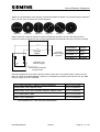
ssue
1
3
5
7
9
11
13
15
17
19
21
23
Change Ref
------------TS001228
TS001552
TS002133
TS002541
TS003362
TS004269
TS004957
TS005846
TS006160
TS006640
TS006850
Date
Aug 2001
29/11/2002
26/06/2003
19/07/2004
5/06/2005
09/08/2006
23/01/2008
03/07/2009
07/12/2010
18/07/2011
26/07/2012
30/05/2013
Issue
2
4
6
8
10
12
14
16
18
20
22
24
Change Ref
TS001135
TS001310
TS002019
TS002438
TS002832
TS003948
TS004932 /TS004597
TS005436
TS005953
TS006174
TS006820
TS007161
Date
09/09/2002
29/04/2003
28/05/2004
30/03/2005
28/09/2005
11/09/2007
19/03/2009
13/04/2010
11/02/2011
05/09/2011
22-05-13
08-08-13
Siemens plc 2001 - 2012. All rights reserved.
All trademarks are acknowledged.
The information contained herein is the property of Siemens plc and is supplied without liability for errors
or omissions. No part may be reproduced or used except as authorised by contract or other written
permission. The copyright and the foregoing restriction on reproduction and use extend to all media in
which the information may be embodied.
667/HB/30000/000
Issue 24
Page 1 of 143
HELIOS GENERAL HANDBOOK
SAFETY WARNING
HEALTH AND SAFETY AT WORK
Safety of Installation and Maintenance Personnel
In the interests of health and safety, when installing, using or servicing this equipment
the following instructions must be noted and adhered to:
(i)
Only skilled or instructed personnel with relevant technical knowledge and
experience, who are also familiar with the safety procedures required when
dealing with modern electrical/electronic equipment, are to be allowed to use
and/or work on the equipment. All work shall be performed in accordance with
the Electricity at Work Regulations 1989.
(ii) Such personnel must take heed of all relevant notes, cautions and warnings in
this Handbook and any other Document or Handbook associated with the
equipment including, but not restricted to, the following:
(a) The equipment must be correctly connected to the specified incoming power
supply.
(b) The equipment must be disconnected / isolated from the incoming power
supply before removing any protective covers or working on any part from
which the protective covers have been removed.
(c) Mains voltages are present in LED and LED (NLM) aspects. Before any
maintenance work is carried out, the mains supply to the aspect must be
isolated / switched off.
(d) WARNING – the earth connections within the CLS with LMF signal head are
‘daisy-chained’ from the Red to Amber and then Green LMF Unit. When
removing either a Red or Amber LMF unit the aspects below will not be
earthed and therefore should not be touched if the controller is powered on.
Ensure that the Earth connections are reconnected after any remedial work
has been carried out.
(e) WARNING – The CLS (ELV) aspects must only be connected to ELV
controllers or else irreparable damage will be caused to the CLS unit.
(f) These signals heads must only be connected to a signal controller that
provides a readily accessible disconnect device (e.g. double pole isolator,
controller switch or master switch), to allow the signal heads to be isolated.
(g) All equipment of conductive material installed in these signal heads must be
bonded to earth e.g. transformers, tactile power supplies etc, unless double
insulated or access to it is restricted to use of a tool.
(h) Where Siemens signal head transformers are used a fuse not exceeding 16
amps must protect the wiring at the controller.
(i) Only trained / competent persons should work on this equipment. This
includes persons who are employed to change bulbs. All wiring has basic
insulation and should be regarded as hazardous, i.e. hazardous voltages are
accessible if the insulation is damaged.
(j) Surfaces within the signal get hot, e.g. lamp, lens and reflector. Therefore
care should be taken when working in such areas.
667/HB/30000/000
Issue 24
Page 2 of 143
HELIOS GENERAL HANDBOOK
(k) Any power tools must be regularly inspected and tested.
(l) Any ladders used must be inspected before use to ensure they are sound
and not damaged.
(m)When using a ladder, before climbing it, ensure that it is erected properly and
is not liable to collapse or move. If using a ladder near a carriageway ensure
that the area is properly coned and signed.
(n) Any personnel working on site must wear the appropriate protective clothing,
e.g. reflective vests, etc.
Safety of Road Users
It is important that all personnel are aware of the dangers to road users that
could arise during repair and maintenance of traffic control equipment.
Ensure that the junction area is coned and signed as necessary to warn
motorists and pedestrians of any dangers and to help protect the personnel
working on the site.
Whilst repairing signals which are in an "all-out" condition, care must be taken to
ensure that no spurious signals are lit during testing which could mislead drivers
or pedestrians. Particular care is required where pedestrian audible devices are
installed, to ensure that no false indications are given during, for example, cable
testing. Personnel should also ensure the safety of pedestrians, especially
children, who may come into contact with parts of the signal poles.
Warning:Helios CLS signals are designed and proven to work with the
monitoring and signal switching circuits of Siemens Traffic Solutions
controller products. Siemens are unable to guarantee their operation
with third party supplied traffic control products, and cannot accept
liability in this respect.
In particular the Lamp Monitor Facility (LMF), fitted to monitor the
operation of individual signals and remove the signal load (switch off)
under fault conditions, may operate inadvertently and extinguish the
signal due to the nature of supplies / lamp switching circuits of third
party controllers.
It is strongly recommended that a separate neutral return (or ground
return in ELV systems) is provided for each green signal. See section
2.3.7 for full detail.
667/HB/30000/000
Issue 24
Page 3 of 143
HELIOS GENERAL HANDBOOK
MAINTENANCE PROVISION (MP)
1.
Product Reference
Helios Traffic Signals
2.
Specifications
The Modular traffic signals are designed to meet the following specifications:
EN12368
H.A. TR2206 Draft 1
BS 7987:2000 (HD 638)
3.
Installation and Commissioning
Methods of Installation and Commissioning are detailed in the Siemens Traffic
Controls document:
667/HB/30000/000 Helios General Handbook
4.
Spares and Maintenance
All maintenance and repairs should be carried out in accordance with the
Siemens Traffic Controls documents:
667/HB/30000/000 Helios General Handbook
5.
Modifications
There are no approved modifications, with the exception of those listed in the
following Siemens Traffic Controls Document:
667/HB/30000/000 Helios General Handbook
6.
Warning
Use of components other than those permitted above or modifications or
enhancements that have not been authorised by Siemens Traffic Controls
Limited will invalidate Type Approval of this product.
667/HB/30000/000
Issue 24
Page 4 of 143
HELIOS GENERAL HANDBOOK
TABLE OF CONTENTS
SAFETY WARNING .................................................................................. 2
MAINTENANCE PROVISION (MP) ........................................................... 4
1.
INTRODUCTION.................................................................................................... 11
1.1 Purpose .............................................................................................................. 11
1.2 Scope ................................................................................................................. 11
1.3 Related Documents ............................................................................................ 12
1.4 Definitions ........................................................................................................... 12
1.5 Tools Required ................................................................................................... 12
1.6 Signal Specification ............................................................................................ 12
1.7 Weights and Dimensions (Signal Heads) ........................................................... 14
2.
SIGNALS AND POLES .......................................................................................... 16
2.1 General ............................................................................................................... 16
2.1.1 Installation at a new site .............................................................................. 20
2.1.2 Upgrading an existing site ........................................................................... 20
2.2 Helios Signals ..................................................................................................... 21
2.2.1 Order of Installation ..................................................................................... 21
2.2.2 Torque Settings ........................................................................................... 21
2.2.3 Signal Head packaging................................................................................ 22
2.2.4 Optical Units ................................................................................................ 24
2.2.4.1 Halogen .................................................................................... 24
2.2.4.2 LED and LED (NLM) ................................................................. 25
2.2.4.3 CLS with LMF and CLS (NLM) ................................................ 25
2.2.4.4 CLS ELV ................................................................................... 25
2.2.4.5 LV Regulatory Signs................................................................ 26
2.2.4.6 ELV Regulatory Signs ............................................................. 26
2.2.4.7 LV LED Regulatory Signs ....................................................... 26
2.3 Assembling and Terminating a Signal Pole ........................................................ 27
2.3.1 Pole Types .................................................................................................. 27
2.3.2 Pole Selection ............................................................................................. 28
2.3.3 Cranked and Formed Poles at Toucan crossings........................................ 30
2.3.4 Erecting the Pole ......................................................................................... 31
2.3.5 Wiring Pole prior to erection ........................................................................ 31
2.3.6 Wiring Pole after erection ............................................................................ 31
2.3.7 Neutral Connections General ...................................................................... 32
2.3.8 Pole Neutral Connections and Terminations (Halogen) .............................. 33
2.3.9 Pole Neutral Connections and Terminations for CLS ELV .......................... 34
2.4 Controller Neutral Connection ............................................................................ 34
2.5 Helios Bracket Assemblies ................................................................................. 35
2.5.1 Extension Bracket Assembly ....................................................................... 35
2.5.2 Side Mounting Bracket ................................................................................ 36
2.6 Signal Head Arrangement .................................................................................. 37
2.6.1 Sacrificial Caps ............................................................................................ 37
2.6.2 Brackets ...................................................................................................... 39
2.6.3 Remove Doors ............................................................................................ 39
2.6.4 Green Arrow (Halogen), CLS with LMF, CLS (NLM) and CLS ELV ............ 40
667/HB/30000/000
Issue 24
Page 5 of 143
HELIOS GENERAL HANDBOOK
2.6.5 Green Arrow (LED and LED (NLM)) ............................................................ 42
2.6.6 Equestrian (Halogen, CLS with LMF, CLS (NLM), CLS ELV, LED and LED
(NLM)) .................................................................................................................... 43
2.6.7 Four in Line ................................................................................................. 43
2.7 Side Boxes ......................................................................................................... 43
2.7.1 Wiring Side Boxes ....................................................................................... 45
2.7.2 Mandatory Arrow ......................................................................................... 45
2.8 Transformers (Halogen) ..................................................................................... 46
2.9 PSUs (LED) ........................................................................................................ 46
2.10 Transformers LED (NLM) ................................................................................... 47
2.11 CLS Unit ............................................................................................................. 48
2.12 CLS ELV Units.................................................................................................... 49
2.13 CLS ELV Type B Transformer Placement .......................................................... 50
2.14 Lamp Monitoring Unit (LMF) ............................................................................... 50
2.15 ELV TRAM Indicator ........................................................................................... 51
2.16 Terminal Blocks .................................................................................................. 53
2.17 Bridge Rectifier ................................................................................................... 53
2.18 Cable Gland........................................................................................................ 53
2.19 Hoods ................................................................................................................. 54
2.19.1 Drilling Hoods .............................................................................................. 55
2.20 Solar Cell ............................................................................................................ 55
2.21 Pedestrian Push Button (Mk 1) ........................................................................... 57
2.21.1 Optional Wiring Kits for Pedestrian Pushbutton (Mk 1) ............................... 57
2.22 L.E.D. Wait Box (Mk 1) ....................................................................................... 58
2.22.1 Optional Wiring Kits for L.E.D. Wait Box (Mk 1) .......................................... 59
2.22.2 L.E.D. Wait Box Doors (Mk 1) ..................................................................... 60
2.23 Nearside Signal and Demand Unit (Mk 1) .......................................................... 61
2.23.1 Nearside Signal Unit (Mk 1)......................................................................... 62
2.23.2 Demand Unit (Mk 1) .................................................................................... 64
2.23.3 Optional Wiring Kits for Nearside Signal Unit and Demand Unit (Mk 1) ...... 65
2.24 Nearside Mk2 Range of units ............................................................................. 66
2.25 Nearside Mk2/Pedestrian Wait Mk2 Pole drilling positions ................................. 67
2.26 Installation of Nearside and WAIT Mk2 fixing kits to pole ................................... 68
2.27 Installation of WAIT, Demand, Signal and Combined Mk2 units to pole ............. 69
2.28 Standard Wait Mk2 Indicator Units ..................................................................... 70
2.28.1 Terminal Block Layout for STD Wait Mk2 Indicator units ............................ 71
2.29 LED Wait Mk2 Indicator Units ............................................................................. 71
2.29.1 Terminal Block Layout for LED Wait Mk2 Indicator units ............................. 72
2.30 CLS Wait ............................................................................................................ 73
2.30.1 CLS Wait Retrofit ......................................................................................... 73
2.30.2 CLS Wait (Production) ................................................................................. 75
2.31 Nearside Mk2 Signal and Demand Units ............................................................ 77
2.31.1 Nearside Mk2 and Mk2 LP Signal Unit ........................................................ 77
2.31.2 Terminal Block Layout for Nearside Signal units ......................................... 79
2.31.3 Nearside Mk2 Demand Unit ........................................................................ 79
2.31.4 Terminal Block Layout for Nearside Demand units ..................................... 80
2.31.5 Nearside Mk2 and Mk2 LP Combined Unit.................................................. 82
2.31.6 Terminal Block Layout for Nearside Combined units ................................... 85
2.32 Radix/Sedgwell Power Supply for Tactile ........................................................... 86
2.33 Backing Boards .................................................................................................. 87
2.33.1 Reflective Tape ........................................................................................... 88
667/HB/30000/000
Issue 24
Page 6 of 143
HELIOS GENERAL HANDBOOK
2.34 Above Ground Detector (AGD) ........................................................................... 88
2.35 Bleep and Sweep Unit ........................................................................................ 89
2.36 Fitting Signal Head to Pole ................................................................................. 91
2.36.1 Adjusting Tilt and Rotation........................................................................... 92
2.36.2 Signal Head to Pole Connection .................................................................. 93
2.36.3 Fit Bulbs (Halogen) ...................................................................................... 94
2.36.4 Fit Doors ...................................................................................................... 94
3.
COMMISSIONING ................................................................................................. 96
3.1 Nearside Monitoring (including pcb upgrade to MK2.LP) ................................... 96
3.1.1 Replacing 667/1/30695/xxx boards with 667/1/33655/XXX ......................... 97
4.
MAINTENANCE ..................................................................................................... 98
4.1 Routine Maintenance Visits ................................................................................ 98
4.2 First Line Maintenance ....................................................................................... 98
4.2.1 Bulb Replacement (Halogen) ...................................................................... 99
4.2.2 Bulb Holder Replacement (Halogen) ........................................................... 99
4.2.3 Transformer Replacement (Halogen) .......................................................... 99
4.2.4 LED or LED (NLM) PCB Replacement ...................................................... 100
4.2.5 PCB Fuse Replacement (LED).................................................................. 102
4.2.6 PSU Replacement (Linear - LED) ............................................................. 102
4.2.7 Transformer Replacement – LED (NLM) ................................................... 103
4.2.8 CLS Unit (Futurit Type) Replacement ....................................................... 104
4.2.9 CLS NLM Unit (Dialight Type) Replacement ............................................. 105
4.2.10 CLS ELV Type A Replacement ................................................................. 106
4.2.11 CLS ELV Type B Replacement ................................................................. 107
4.2.12 LMF Fuse Replacement ............................................................................ 108
4.2.13 LMF Unit Replacement .............................................................................. 108
4.2.14 Tube Replacement .................................................................................... 109
4.2.15 Aspect Door Replacement (Halogen) ........................................................ 110
4.2.16 Aspect Door Assembly Replacement (LED and LED (NLM)) .................... 111
4.2.17 CLS with LMF, CLS (NLM) Door Replacement ......................................... 112
4.2.18 CLS ELV Door Replacement ..................................................................... 113
4.2.19 Regulatory Sign Door Replacement .......................................................... 114
4.2.20 Door Clip Replacement ............................................................................. 114
4.2.21 Hood Replacement .................................................................................... 114
4.2.22 Lens or Reflector Replacement (Halogen) ................................................ 114
4.2.23 Lens Replacement (LED or LED (NLM)) ................................................... 115
4.2.24 Lens Replacement CLS with LMF or CLS (NLM) ...................................... 116
4.2.25 Lens Replacement CLS ELV ..................................................................... 117
4.2.26 Sacrificial Cap Replacement ..................................................................... 117
4.2.27 Sacrifical Caps – Screw Tightening Procedure ......................................... 118
4.2.28 Modular Unit Replacement ........................................................................ 118
4.3 Second Line Maintenance ................................................................................ 119
APPENDIX A – DRAWINGS ................................................................. 120
APPENDIX B – SPARES LIST ............................................................. 123
APPENDIX C - Visual Identification of ELV Compatible PCB’s ....... 128
APPENDIX D - Helios Signal Head Screw Fixing Procedure ........... 131
Appendix E- TRAM Indicator Cable connections and Aspects ...... 139
667/HB/30000/000
Issue 24
Page 7 of 143
HELIOS GENERAL HANDBOOK
INDEX .................................................................................................... 142
FIGURES
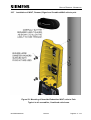
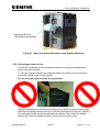
Figure 1 – Helios front view ........................................................................................... 16
Figure 2 – Helios TRAM indicator front view ................................................................. 17
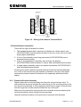
Figure 3 CLS ELV Type A ............................................................................................. 18
Figure 4 CLS ELV Type B ............................................................................................. 18
Figure 5 – Helios side view ........................................................................................... 19
Figure 6 – Three Aspect Halogen Internal Fitting .......................................................... 22
Figure 7 – Three Aspect LED Internal Fitting ................................................................ 23
Figure 8 – Three Aspect LED (NLM) Internal Fitting ..................................................... 23
Figure 9 – Three Aspect CLS with LMF Internal Fitting ................................................. 24
Figure 10 – Typical Signal Pole Assembly showing heights for compliance with Traffic
Signs Regulations .................................................................................................. 28
Figure 11 – Signal Pole Assembly showing useful dimensions for Pole Selection and
planting depth ........................................................................................................ 30
Figure 12 – Wiring of the Neutral Terminal Block .......................................................... 35
Figure 13 – Extension Bracket ...................................................................................... 36
Figure 14 – Side mounting bracket ............................................................................... 36
Figure 15 – Example Mounting Arrangements .............................................................. 37
Figure 16 – Sacrificial Cap parts ................................................................................... 38
Figure 17 – Sacrificial Cap assembly ............................................................................ 39
Figure 18 – Using a screwdriver to open the door clip .................................................. 39
Figure 19 – Door clip detail ........................................................................................... 40
Figure 20 – Green Arrow mask ..................................................................................... 40
Figure 21 CLS ELV Type B Anti-rotation Clip ................................................................ 42
Figure 22 CLS ELV Arrow Mask ................................................................................... 42
Figure 23 – Side box showing fixing plates and conduit ................................................ 44
Figure 24 – Side box fitted on right of main signal head................................................ 44
Figure 25 – End cap fitted to side box ........................................................................... 44
Figure 26 – Regulatory Sign internal fitting ................................................................... 45
Figure 27 – Signal Head with Mandatory Arrow fitted ................................................... 45
Figure 28 – Transformer fitted to floor of case .............................................................. 46
Figure 29 – PSU assembly fitted into case.................................................................... 47
Figure 30 – LED (NLM) Transformer Fitted to Aspect ................................................... 47
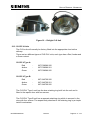
Figure 31 – Futurit CLS Unit .......................................................................................... 48
Figure 32 – Dialight CLS Unit ........................................................................................ 49
Figure 33 Transformer mounting points ........................................................................ 50
Figure 34 – CLS with LMF............................................................................................. 51
Figure 35 – TRAM Indicator with door open .................................................................. 51
Figure 36 – TRAM Indicator rear view showing Keyhole slots ...................................... 52
Figure 37 – TRAM Indicator showing keyhole slot from the front .................................. 53
Figure 38 – Bridge Rectifier........................................................................................... 53
Figure 39 – Standard Hood fitting ................................................................................. 54
Figure 40 – Angled Hood fitting ..................................................................................... 55
Figure 41 – Solar Cell.................................................................................................... 56
Figure 42 – Pedestrian push button unit........................................................................ 57
Figure 43 – LED Wait Box ............................................................................................. 59
Figure 44 – LED Wait Box Door Assembly (Mk 1) ........................................................ 61
667/HB/30000/000
Issue 24
Page 8 of 143
HELIOS GENERAL HANDBOOK
Figure 45 – Toucan Nearside Signal and Demand Unit ................................................ 62
Figure 46 – Nearside Signal - Shows the Two PCBs (Mk 1) ......................................... 63
Figure 47 – Red Man PCB from Puffin Nearside Unit (Mk 1) ........................................ 63
Figure 48 – Nearside Signal Shown with Red Man/Cycle/Equestrian PCB Removed (Mk
1) ............................................................................................................................ 64
Figure 49 – Demand Unit .............................................................................................. 65
Figure 50: Drilling guide for Nearside and Pedestrian WAIT range ............................... 67
Figure 51: U-bolt and cable gland installation (Mk2) ..................................................... 68
Figure 52: Mounting of Nearside/Pedestrian WAIT units to Pole. ................................. 69
Figure 53 - Standard Wait Mk2 Indicator unit ................................................................ 70
Figure 54 - LED Mk2 Wait Box ...................................................................................... 72
Figure 55 CLS Wait Retrofit and MK2 Spacer ............................................................... 74
Figure 56 CLS Wait Retrofit reverse side showing the Driver PCB ............................... 74
Figure 57 CLS Wait Unit................................................................................................ 75
Figure 58 – Nearside Mk2 Signal Unit ........................................................................... 78
Figure 59 – Nearside Mk2 Demand Unit ....................................................................... 80
Figure 60 – Nearside Mk2 Combined Unit .................................................................... 83
Figure 61 – Nearside Mk2 Combined Unit - Shows the Three PCBs ............................ 84
Figure 62 – Radix power supply .................................................................................... 87
Figure 63 – Backing board fixings ................................................................................. 88
Figure 64 – AGD fitted to signal head bracket ............................................................... 89
Figure 65 – Bleep and Sweep Signal Head Arrangement ............................................. 90
Figure 66 – Bleep & Sweep Unit Mounted in Signal Aspect .......................................... 90
Figure 67 - Bleep and Sweep Microphone and Speaker Mounting ............................... 91
Figure 68 – Bottom bracket fitted .................................................................................. 92
Figure 69 – Angles of Tilt .............................................................................................. 92
Figure 70 – Angle of Rotation ........................................................................................ 93
Figure 71 – Pole Cap fitted............................................................................................ 94
Figure 72 – Door Clip closed ......................................................................................... 95
Figure 73 – LED PCB front.......................................................................................... 101
Figure 74 – LED PCB rear .......................................................................................... 101
Figure 75 – LED (NLM) PCB front ............................................................................... 101
Figure 76 – PSU White Molex Connectors .................................................................. 103
Figure 77 – LED (NLM) Transformer ........................................................................... 104
Figure 78 – CLS Unit fitted into door ........................................................................... 104
Figure 79 – Futurit CLS Unit, Retaining Ring and retaining Clips ................................ 105
Figure 80 – ‘Pip’ at the top of the Futurit CLS Unit ...................................................... 105
Figure 81 – Futurit CLS engaging slot ......................................................................... 105
Figure 82 – Dialight CLS Unit ...................................................................................... 106
Figure 83 – ELV CLS LABEL ...................................................................................... 106
Figure 84 CLS ELV Type B anti-rotation clip ............................................................... 107
Figure 85 – Top view of a LMF unit ............................................................................. 108
Figure 86 – LMF with Cover Removed ........................................................................ 109
Figure 87 – LMF unit within a signal aspect ................................................................ 109
Figure 88 – Door assembly (Halogen)......................................................................... 110
Figure 89 – Lens with seal in place ............................................................................. 110
Figure 90 – Reflector with seal in place....................................................................... 111
Figure 91 – LED Aspect Door ..................................................................................... 112
Figure 92 – LED (NLM) Aspect Door........................................................................... 112
Figure 93 – CLS Aspect Door ..................................................................................... 113
Figure 94 – Fir-tree clips ............................................................................................. 114
667/HB/30000/000
Issue 24
Page 9 of 143
HELIOS GENERAL HANDBOOK
Figure 95 – Separated Modules .................................................................................. 119
Figure 96 – Front View ................................................................................................ 120
Figure 97 – Rear View................................................................................................. 121
Figure 98 – Top View .................................................................................................. 122
Figure 99 – Underside View ........................................................................................ 122
667/HB/30000/000
Issue 24
Page 10 of 143
HELIOS GENERAL HANDBOOK
1.
INTRODUCTION
1.1 Purpose
This handbook gives a general description and specification along with the
procedures for installation, commissioning and maintenance for the following
versions of Helios Signal Head:
CLS with LMF Signal Aspect.
CLS (NLM) Signal Aspect.
CLS ELV Signal Aspect.
LED.
LED (NLM).
LED TRAM Indicator (ELV).
Tungsten Halogen.
In addition the manual also gives a general description and specification along
with the procedures for installation, commissioning and maintenance for various
other equipment including:
Wait Indicator.
LED Wait Indicator.
CLS Wait Indicator.
Nearside Indicator.
Demand unit.
1.2 Scope
This handbook is written for the Helios Signal Head and is made up of the
sections listed below:
Safety Warning
Maintenance Provision (MP)
Section 1
Introduction
Section 2
Signals and Poles
Section 3
Commissioning
Section 4
Maintenance
Appendix A Drawings
Appendix B Spares List
Index
667/HB/30000/000
Issue 24
Page 11 of 143
HELIOS GENERAL HANDBOOK
1.3 Related Documents
667/HE/20661/000 - General Principles
667/HE/20662/000 - Signals and Poles (for reference only)
667/HE/20663/000 - Detectors and Cable Terminations
667/HE/20664/000 - Installation and Testing
667/HE/20665/000 - Above Ground Detectors
1.4 Definitions
AGD
CET
CLS
ELV
HI
IEE
LED
LMF
LSLS
LV
MVD
NLM
PBU
PI
RAG
S/S
STC
STS
Above Ground Detector
Cable Earth Terminal
Central Light Source
Extra Low Voltage
High Intensity
Institute of Electrical Engineers
Light Emitting Diode
Lamp Monitoring Facility
Low Voltage / Serial Lamp Switch
Low Voltage
Microwave Vehicle Detector
Non Lamp Monitored
Push Button Unit
Periodic Inspections
Red Amber Green (3-Aspect signal head)
Stainless steel
Siemens Traffic Controls
Site to Scale (drawing)
1.5 Tools Required
As well as a standard Installers tool kit, the following are required when installing
and maintaining Helios:
Pozidriv screwdriver no. 2 or 3, 13 mm and 17 mm spanners or sockets and an
8 mm Allen key are necessary to install and adjust the lanterns.
Where side boxes are to be fitted, a 19 mm drill bit is needed to fit the conduit.
Where a solar cell is to be fitted, a 20 mm drill bit is needed.
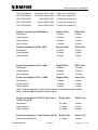
1.6 Signal Specification
Model
667/1/30200/ETC
Description
Current Consumption
230 V / 50Hz
Tungsten Halogen - 0.23 A per optical unit
667/1/30198/001
Red LED - 0.105 A per optical unit
667/1/30198/002
Amber LED - 0.121 A per optical unit
667/1/30198/003
Green LED - 0.09 A per optical unit
667/HB/30000/000
Issue 24
Page 12 of 143
HELIOS GENERAL HANDBOOK
667/1/30198/004
Up Arrow Green LED - 0.06 A per optical unit
667/1/30198/005
L/R Arrow Green LED - 0.08 A per optical unit
667/1/30200/907
Red (NLM) LED - 0.102A per optical unit
667/1/30200/908
Amber (NLM) LED - 0.117A per optical unit
667/1/30200/906
Green (NLM) LED - 0.103A per optical unit
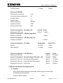
POWER CONSUMPTION (LED SIGNALS)
BRIGHT (230V)
Dim (160v)
Red Aspect
24 watts
6 watts
Amber Aspect
28 watts
7 watts
Green Aspect
20 watts
5 watts
Green Arrow
16 watts
4 watts
POWER CONSUMPTION (NLM – LED)
BRIGHT (230V)
Dim (160v)
Red Aspect
24 watts
7 watts
Amber Aspect
28 watts
8 watts
Green Aspect
24 watts
7 watts
Power Consumption (CLS + LMF)
Bright (230v)
Dim (160v)
Red Aspect
28 watts
12 watts
Amber Aspect
28 watts
12 watts
Green Aspect
28 watts
13 watts
Power Consumption (CLS – NLM)
Bright (230v)
Dim (160v)
Red Aspect
13 watts
3 watts
Amber Aspect
13 watts
3 watts
Green Aspect
16 watts
4 watts
NOTE – CLS with LMF must not have a Dim or Bright voltage between 180V and 200V.
NOTE – CLS with LMF only supports 160V Dimming.
Power Consumption CLS ELV Type A and
CLS ELV Type B
Bright (48v)
Dim (27.5v)
Red Aspect
12 watts
4 watts
Amber Aspect
12 watts
4 watts
Green Aspect
12 watts
4 watts
Power Consumption – Tram Indicator (ELV)
Bright (48v)
Dim (27.5v)
Centre Dot (Always on)
11 watts
3 watts
667/HB/30000/000
Issue 24
Page 13 of 143
HELIOS GENERAL HANDBOOK
All other states
11 watts
3 watts
Reference EN12368 Performance level class
A3.2
Luminous intensity distribution
M
Phantom class
5
Symbol class
S1
Impact resistance
IR2/IR3
Ingress protection
IP55
Environmental class
A/B
Power Consumption – Reg Sign (LV)
Current Power
Measured at 230 volts
320mA
75 Watts
Power Consumption – LED Reg Sign (ELV)
Measure at 48 volts
7 Watts
Power Consumption – LED Reg Sign (LV)
Measure at 230VAC
8 Watts
Power Consumption – CLS Wait
Bright (48v)
Dim (27.5v)
Retrofit
12 watts
4 watts
MK2 Wait Box
12 watts
4 watts
Power Consumption – LED Wait Box
Current
Power
Measured at 48 volts
100mA
4.8 Watts
Power Consumption – Nearside Signal / Demand Unit
Current
Power
Measured at 48 volts – Red Man/Cycle/Equestrian
300mA
16 Watts
Measured at 48 volts – Green Man/Cycle/Equestrian
300mA
16 Watts
Measured at 48 volts – Call Accept
100mA
6 Watts
1.7 Weights and Dimensions (Signal Heads)
a) Weights
Note: Except where otherwise mentioned, lantern weight includes doors,
moulded hoods and brackets.
3 Aspect 200mm lantern
667/HB/30000/000
15 Kg
Issue 24
Page 14 of 143
HELIOS GENERAL HANDBOOK
3 Aspect 200mm lantern (doors removed)
2 Aspect 200mm lantern
1 Aspect regulatory sign
1 Aspect regulatory sign (door removed)
1 Aspect TRAM indicator (fully equipped)
Pedestrian push button
4.0m Pole
Pair of mounting brackets
9 Kg
11 Kg
3 Kg
2.25 Kg
9.5 Kg
3.6 Kg
68 Kg
3.2 Kg
b) Dimensions (including backing boards)
3 in line
4 in line
3 in line and side box
3 in line and side boxes at each side
667/HB/30000/000
Issue 24
1116 mm H x 468 mm W
1450 mm H x 468 mm W
1116 mm H x 841 mm W
1116 mm H x 1214 mm W
Page 15 of 143
HELIOS GENERAL HANDBOOK
2.
SIGNALS AND POLES
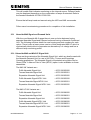
2.1 General
The Helios range of traffic signals has been developed to give optimum clarity,
reliability and longevity with a pleasing appearance.
It incorporates newly developed lens form and masking patterns, which ensure
that the signal is extremely clear and easy to see in all conditions.
There are tungsten halogen and LED aspects, which may be mixed in one signal
head. For example, the traffic signal at a pedestrian crossing could have red and
amber halogen aspects with a green LED aspect, since the green would be on
most of the time.
CLS with LMF, CLS (NLM) and LED (NLM) aspects should NOT be mixed in a
signal head with tungsten halogen and LED aspects as the visible switching on
and off of a CLS with LMF, CLS (NLM) and LED (NLM) aspect is instantaneous.
The CLS (NLM) and LED (NLM) is not compatible with the STC Controller lamp
monitoring and should be driven from a separate output if the tungsten halogen
lamps, CLS with LMF and/or LED are required to be monitored.
NLM LED signals can be monitored with the Retrofit LV controllers but the
current capability for Halogen signals is reduced.
CLS ELV aspects should ONLY be connected to Siemens ST900 (ELV) and
ST750 (ELV) controllers as the supply voltage to an aspect is 48V. The CLS ELV
is compatible with the lamp monitoring facility of the ST900 (ELV) and ST750
(ELV) controllers, with each aspect having a visible switching on and off which is
instantaneous. NOTE – The CLS ELV does not utilise a LMF Unit.
Within the ELV HELIOS family are LED regulatory signs and a TRAM indicator
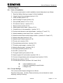
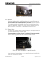
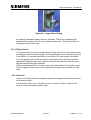
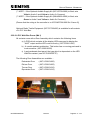
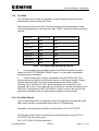
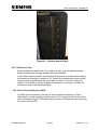
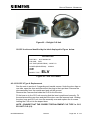
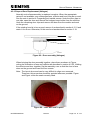
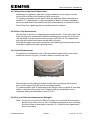
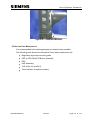
The design incorporates a sacrificial cap that is designed to break on impact,
absorbing part of the force and protecting the signal head from major damage.
Figure 1 – Helios front view
667/HB/30000/000
Issue 24
Page 16 of 143
HELIOS GENERAL HANDBOOK
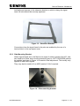
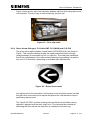
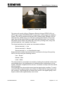
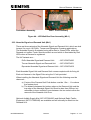
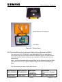
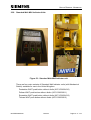
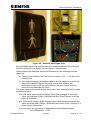
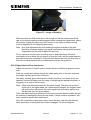
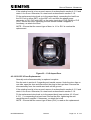
Figure 2 – Helios TRAM indicator front view
The basic three-aspect lantern assembly is constructed on a modular principle.
Each aspect is self-contained and consists of one of the following:
Halogen Option
A high intensity tungsten halogen lamp and lamp-holder fitted into a reflector
assembly, a red, amber or green coloured lens and a lamp transformer fitted with
sufficient cable on its input to reach the pole cap wherever the lantern is mounted
on the pole.
LED Option
An LED board is fitted behind a clear lens and connected to a PSU/inductor
assembly for each aspect. The LEDs are linked in a number of strings around the
board, connected so that if a string fails it does not leave a dark area. The
inductor continually measures the output current of the board and if that should
fall below 80%, the fuse blows and a fault is sent to the controller.
LED (NLM) Option
An LED board is fitted behind a clear lens and connected to a dual winding
transformer. The LEDs are linked in a number of strings around the board,
connected so that if a string fails it does not leave a dark area. This option does
not allow any Lamp Monitoring.
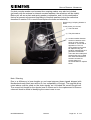
CLS with LMF Option
The Central Light Source (CLS) is fitted behind a clear lens and is connected to
the Lamp Monitoring Facility assembly for each aspect. The CLS Unit is a sealed
unit that contain a number of high intensity LEDs. There are three different types
of CLS units, a Red, an Amber and a Green. The LMF unit measures the output
current of the CLS unit and if that should fall below 80%, the fuse blows and a
fault is detected by the controller. The LMF unit is connected to the controller
phase output.
CLS (NLM) OPTION
The Central Light Source (CLS) is fitted behind a clear lens and is connected
directly to the controller phase output. The CLS Unit is a sealed unit that contain
a number of high intensity LEDs. There are three different types of CLS units, a
Red, an Amber and a Green. This option may be monitored by the ST800, 900
700 and 750 retrofit controller facilities .
667/HB/30000/000
Issue 24
Page 17 of 143
HELIOS GENERAL HANDBOOK
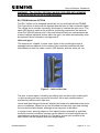
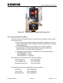
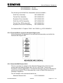
CLS ELV OPTION
The Central Light Source (CLS) is fitted behind a clear lens and is connected
directly to the ST900 (ELV) or ST750 (ELV) controller phase output. The output
from the controller is 48V (bright) with the controller capable of performing Lamp
Monitoring of each aspect. The CLS ELV unit contains a number of high intensity
LEDs. There are two different types of CLS ELV units, each type has a Red,
Amber and a Green variant.
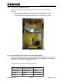
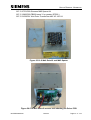
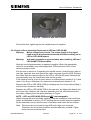
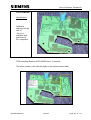
CLS ELV Type A
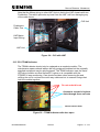
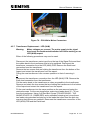
Figure 3 CLS ELV Type A
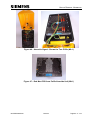
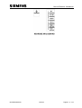
CLS ELV Type B
Figure 4 CLS ELV Type B
667/HB/30000/000
Issue 24
Page 18 of 143
HELIOS GENERAL HANDBOOK
WARNING – The CLS ELV OPTION CAN ONLY BE USED WITH SIEMENS
ST900 (ELV) and ST750 (ELV) CONTROLLERS.
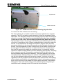
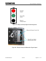
ELV TRAM indicator OPTION
This ELV Helios unit is designed specifically for use with light rail and TRAMS.
The Light colour is white and the aspects take the form of a bar of discrete lights.
The central dot is normally constantly illuminated to indicate the optic as on. The
same LED driver is used so the profile for monitoring purposes is the same as
other ELV HELIOS optical units. If the unit becomes faulty no attempt should be
made to replace individual drivers within the optic, the whole sub assembly must
be replaced. More information see Appendix E
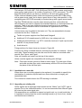
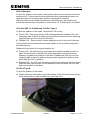
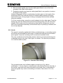
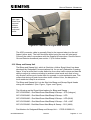
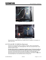
Helios all types
The aspects are “clipped” to each other. Holes in the mouldings provide a
passage between aspects for the cables. Each moulding contains drill-start
indentations to allow for cable conduit, AGD detector sockets, solar cell, etc.
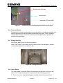
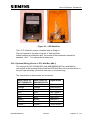
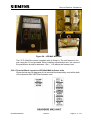
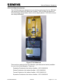
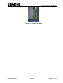
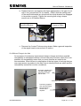
Figure 5 – Helios side view
The door to each aspect is fixed by two sliding clips on either side, enabling left
or right opening and easy removal of the door. As an anti-vandal measure,
screws may hold the door clips shut.
Hoods and their fittings will also be supplied but need to be attached to the doors
prior to installation. Helios has its own moulded hood but may use most existing
louvred and tunnelled hoods, although some may need to be drilled.
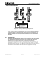
If a green arrow, box sign aspect or four-aspect lantern assembly is specified,
the extra module or modules required can be added to the basic signal head in
combinations as shown in section 2.6. Fittings to secure each module to the
basic lantern will be supplied with each single aspect.
667/HB/30000/000
Issue 24
Page 19 of 143
HELIOS GENERAL HANDBOOK
The halogen, CLS with LMF, CLS (NLM) and CLS ELV green arrow may have a
green arrow mask placed in a number of positions in 22.5 increments. The LED
and LED (NLM) options can have up (ahead) or left and right green arrows
PCB’s fitted as standard (these utilise sub equipment green LED PCBs) along
with a green arrow mask, but to have a green arrow in any other position, a fully
equipped green LED PCB assembly is required along with a green arrow mask.
The ELV TRAM indicator uses the same housing as other units within the
HELIOS family and can be clipped onto standard aspects or used stand alone as
required. There is no room inside the housing however to fit any ancillary
equipment. The information below is therefore not applicable to the TRAM
indicator module.
Various items may be added to the basic unit. They are assembled to bosses
moulded into the box. These are:
Tactile unit power supplies from Radix and Sedgwell
Additional 50 VA transformers for AGD drive, low voltage wait, etc.
Additional terminal blocks, e.g. STCL controller terminal, HI pole cap terminal
and MD 12-way brown blocks.
Audio drive kit.
Fixing positions for these items are shown in Figure 96.
Positions for fitting overhead detector sockets are provided in recesses – three to
each side. These recesses may also be used for the side box mounted cable
conduit. See Figure and Figure .
Solar cell bosses are located on the top of the module.
Helios modular signals are compatible with existing pole drillings.
Note: Fibre optic arrows cannot be fitted to Helios signs. The new type of lens
and mask renders fibre optics unnecessary and the 200 mm arrow takes
the place of the old fibre optic.
2.1.1 Installation at a new site
Where there are no existing signals to be replaced, it is possible to specify the
combination of modules required and have them delivered in a largely preassembled state.
This method is suitable where the STS drawing is available.
2.1.2 Upgrading an existing site
Helios signals are a significant improvement on the “Mellor” and “HITS” type of
signals. Due to the visual differences, it is not recommended that different types
be mixed on the same signal pole.
Sub-assemblies are available to expand a signal head, e.g. to add a side box. It
is important to ensure that the correct backing boards (e.g. four-in-line), hoods
and brackets are called for.
667/HB/30000/000
Issue 24
Page 20 of 143
HELIOS GENERAL HANDBOOK
2.2 Helios Signals
2.2.1 Order of Installation
The recommended order in which installation should take place is as follows:
1. Read the Safety Warning on page 2 of this Handbook.
2. Unpack items from packaging (section 2.2.3)
3. Install pole (section 2.3)
4. Add mounting kit to pole (section 2.3)
5. Wire pole (section 2.3.5 or 2.3.6)
6. Fit extension arm(s) (section 2.5.1)
7. Remove doors (section 2.6.3)
8. Adjust green arrow mask (section 2.6.4)
9. Complete four-in-line assembly (section 2.6.7)
10. Connect side boxes to main signal head (sections 2.7 and 2.7.1)
11. Attach mandatory arrow lens to door (section 2.7.2)
12. Attach terminal blocks and/or bridge rectifier (sections 2.15 and 2.17)
13. Attach cable gland (section 2.18)
14. Attach hoods to doors (section 2.19)
15. Fit solar cell (section 2.20)
16. Fit pedestrian push button (section 2.21)
17. Fit tactile power supply (section 2.32)
18. Attach reflective tape (section 2.33.1)
19. Fit backing boards (section 2.33)
20. Fit AGD (section 2.34)
21. Fit signal head to pole (section 2.36)
22. Adjust angles of tilt and rotation (section 2.36.1)
23. Connect wiring between pole and signal head (section 2.36.2)
24. Fit pole cap (section 2.36.2)
25. Fit bulbs and doors (sections 2.36.3 and 2.36.4)
= New installations only
= Optional, depending on specification
= Halogen only
2.2.2 Torque Settings
The recommended torque settings are as follows:
Plas-Tech 25 screws – 0.8 Nm (These are factory set and should not need
adjusting, setting or testing).
667/HB/30000/000
Issue 24
Page 21 of 143
HELIOS GENERAL HANDBOOK
M10 screws and bolts – 20 Nm
As signal heads rely on the security of their mounting fixings these fixings must
be torqued up and the recommended procedure for this is found in appendix D.
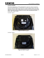
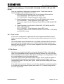
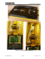
2.2.3 Signal Head packaging
Helios modular signals are supplied boxed in two forms:
The three aspect box can contain a one-, two- or three-aspect head with
attached brackets with the backing boards loose in the box. Hoods and other
fixings are supplied in a separate box. Backing boards for a four in line assembly
are attached to the outside of the box.
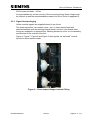
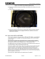
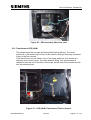
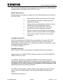
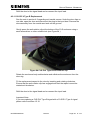
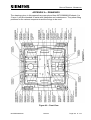
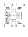
Figure 6, Figure 7, Figure 8 and Figure 9 show typical “as delivered” internal
layouts for three-aspect heads.
Figure 6 – Three Aspect Halogen Internal Fitting
667/HB/30000/000
Issue 24
Page 22 of 143
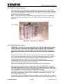
HELIOS GENERAL HANDBOOK
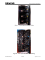
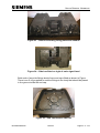
Figure 7 – Three Aspect LED Internal Fitting
Figure 8 – Three Aspect LED (NLM) Internal Fitting
667/HB/30000/000
Issue 24
Page 23 of 143
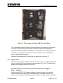
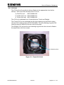
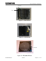
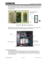
HELIOS GENERAL HANDBOOK
Figure 9 – Three Aspect CLS with LMF Internal Fitting
The single aspect box will contain a single module with its side box mounting kit
or the four-in-line fixing kit, and all the hoods and fixings for the assembly.
All these elements should be assembled on the ground prior to fixing to the pole.
Lanterns are assembled in accordance with the requirements of the STS for
primary and secondary signals.
Assembly and attachment of side boxes are described in section 2.7.
2.2.4 Optical Units
Helios only has 200 mm aspects with the exception of some regulatory signs that
may be notionally 300 mm (actual size approximately 270 mm). The Mellor lens
is not interchangeable with the Helios lens.
200 mm Aspects for Vehicle, Pedestrian and Green Arrow Signals
2.2.4.1
Halogen
A pre-focused 12 V 50 W Tungsten Halogen lamp is mounted in a parabolic
reflector fitted behind a specially designed medium wide-angle lens of selfcoloured acrylic material. Rear access is provided to the lamp holder to facilitate
667/HB/30000/000
Issue 24
Page 24 of 143
HELIOS GENERAL HANDBOOK
lamp changing without exposing the reflector to the elements and possible
surface damage.
The lens is screened with a specially designed mask, to reduce the phantom
effect.
The lamp voltage is derived from a small step-down transformer, one per signal
aspect mounted in the lamp body.
2.2.4.2
LED and LED (NLM)
The 247 pre-focussed LEDs on the standard red, amber and green aspects are
mounted on a PCB that is held at a set distance from a specially designed
medium wide angle lens made of clear acrylic material. The LEDs have the
correct colour wavelength, intensity and viewing angle to achieve the specified
colour, brightness and medium wide beam.
The lens is screened with a specially designed mask to reduce the phantom
effect.
Rear access is provided to the PCB to allow it to be replaced easily. Note that
mains voltages are present in LED aspects and the supply to the aspect must be
isolated or switched off before any work is carried out.
The supply voltages to the LED PCB are derived from a small switch mode PSU
mounted in the aspect case and powered from the respective controller output.
The supply voltages to the LED (NLM) PCB are derived from a dual winding
transformer mounted in the aspect case and powered from the respective
controller 230v phase output.
2.2.4.3
CLS with LMF and CLS (NLM)
A pre-focussed CLS unit is held in position at a set distance from a specially
designed medium wide angle lens made of clear acrylic material. The CLS is a
sealed unit which is available in Red, Amber and Green and is designed to
achieve the specified colour and brightness output.
The lens is screened with a specially designed mask to reduce the phantom
effect.
The 230v supply voltage for the CLS with LMF is derived from the LMF unit. The
LMF unit monitors the load current of the CLS unit and is powered from the
respective controllers 230v phase output.
The 230v supply voltage for the CLS (NLM) is derived from the respective
controller 230v phase output.
2.2.4.4
CLS ELV
A pre-focussed CLS ELV unit is held in position at a set distance from a specially
designed medium wide angle lens made of clear acrylic material. The CLS ELV
is available in Red, Amber and Green and is designed to achieve the specified
colour and brightness output.
The lens is screened with a specially designed mask to reduce the phantom
effect.
667/HB/30000/000
Issue 24
Page 25 of 143
HELIOS GENERAL HANDBOOK
The 48V supply voltage for the CLS ELV is derived from the ST900 (ELV) or
ST750 (ELV) controller phase outputs. The Controller phase driver PCBs monitor
the load current of the CLS ELV unit.
2.2.4.5
LV Regulatory Signs
Two 230 mm (9”) 6 W fluorescent tubes are mounted in front of a metal reflector.
The tubes are connected in such a way as to provide protection against total
signal failure.
The lens is formed from a flat acrylic sheet upon which any of the mandatory
signs may be printed in full colour. Most regulatory signs are delivered with the
lenses fitted into the door of the module using a mastic bead sealant. Mandatory
arrow signs come as a kit with separate sealant to allow fitting on site to
customer requirements.
2.2.4.6
ELV Regulatory Signs
Two 6 LED arrays are mounted onto a plate along with a control module and
connection terminal block. This ELV Module (667/1/33510/000) is then mounted
into a body using 3 off M4 x 10mm Plastech 25 pan head pozi screws. The
required door/lens is fitted to the body.
The lens is formed from a flat acrylic sheet upon which any of the mandatory
signs may be printed in full colour. Most regulatory signs are delivered with the
lenses fitted into the door of the module using a mastic bead sealant. Mandatory
arrow signs come as a kit with separate sealant to allow fitting on site to
customer requirements.
2.2.4.7
LV LED Regulatory Signs
Two 6 LED arrays are mounted onto a plate along with a control module, mains
transformer and connection terminal block. This LV Module (667/1/33510/230) is
then mounted into a body using 3 off M4 x 10mm Plastech 25 pan head pozi
screws. The required door/lens is fitted to the body.
The lens is formed from a flat acrylic sheet upon which any of the mandatory
signs may be printed in full colour. Most regulatory signs are delivered with the
lenses fitted into the door of the module using a mastic bead sealant. Mandatory
arrow signs come as a kit with separate sealant to allow fitting on site to
customer requirements.
Note: At this time, Siemens type controllers are unable to lamp monitor the LV
LED Regulatory Sign.
667/HB/30000/000
Issue 24
Page 26 of 143
HELIOS GENERAL HANDBOOK
2.3 Assembling and Terminating a Signal Pole
2.3.1 Pole Types
General -
PVC-covered Poles
667/2/01459/ETC
Galvanised Poles
667/2/03686/ETC
Cranked Pole
667/2/30230/000-001
667/2/30231/000-001
Formed Pole
667/2/28107/001-003
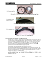
NOTE – If the Pole is a Formed or Cranked Type or the Pole has an
Extension Arm fitted, an Anti-Rotate Rod must be fitted to the Pole (See
Figure 10).
Part Number for Anti-Rotate Rod – 667/2/10094/000
667/HB/30000/000
Issue 24
Page 27 of 143
HELIOS GENERAL HANDBOOK
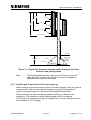
2.3.2 Pole Selection
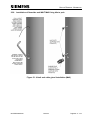
Centre Line of Amber
Lower
edge of
container
2.4m min to 4.0m max
(see note 1)
Pedestrian
Pushbutton
Box
2.1m min
(see note 3)
400 - 550mm
(see note 5)
2.1m min to
2.6m max
(see note 2)
1.0m min to
1.1m max
(see note 4)
Ground level
Cables entering
via slot in pole
Concrete
Anti-rotate rod
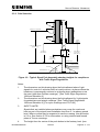
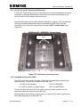
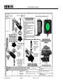
Figure 10 – Typical Signal Pole Assembly showing heights for compliance
with Traffic Signs Regulations
Notes:
1.
The dimensions on this drawing show the limits allowed where ‘Light
signals for control of vehicular traffic at road junctions, at places where the
headroom is permanently reduced or at places where pedestrians cross
the road (other than Pelican crossings)’. [See Traffic Signs Regulations
1994 and Schedule 8.]
2.
The dimensions on this drawing show the limits allowed for ‘Light signals
for pedestrians and animal crossings’. [See Traffic Signs Regulations
1994 and Schedule 8.] [For cycle crossings see LTN 1/98.]
3.
SAFETY NOTE!
Signals that are installed where pedestrians may cross the road must
have no part of the signal head installation less than 2.1 m above ground
level. Where cyclists may be expected to use the crossing, this dimension
is 2.3 m. See section 2.3.3 for information on using cranked and formed
poles at Toucan crossings.
4.
The height from the centre of the push button to the footway level. [see
667/HB/30000/000
Issue 24
Page 28 of 143
HELIOS GENERAL HANDBOOK
LTN 1-98]. This dimension applies if the push button is a single housing or
a separate housing Demand/Display unit.
5.
The height dimension of the pushbutton unit applies to a single housing or
separate housing Demand/Display unit [see TR2181C].
----------------------
The following information is provided to enable pole length requirements and
planting depths to be determined. This assumes a 667/2/01459/ETC pole and a
3-aspect signal. Confirm dimensions using appropriate or latest drawings.
Note that a 3.75 m pole will only be used for amber centres below about 2.6 m.
Example 1 - Obtaining heights to amber centre line with nominal pole lengths by
varying planting depth. m)
4000 - 2800 - 505 = Planting depth in mm = 695 mm.
Note – see FIGURE and FIGURE for dimensions
Example 2 - Using common pole lengths and a planting depth of 700 mm, the
centre of the amber would be:
Pole Length (m)
Planting Depth (mm)
Amber centre line
4
700
~2.80 m
5
700
~3.80 m
5.5
700
~4.30 m
6
700
~4.80 m
Example 3 - To obtain the pole length required for a given centre of the amber,
green or the clearance height:
Pole length required = (Height to amber C/L + 505 mm + planting depth)
Pole length required = (Height to green C/L+ 835 mm + planting depth)
Pole length required = (Clearance Height + 1065 mm + planting depth)
Therefore, if the height of the green C/L is to be 2.5 m, the pole needs to be at
least 2.5 m + 0.84 m + 0.61 m = 3.95 m.
Note – see FIGURE and FIGURE for dimensions
667/HB/30000/000
Issue 24
Page 29 of 143
HELIOS GENERAL HANDBOOK
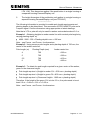
505mm
835mm
Amber C/L
1065mm
Green C/L
Min clearance line
Ground level
Planting Depth
Concrete
Cables entering
via slot in pole
Anti-rotate rod
Figure 11 – Signal Pole Assembly showing useful dimensions for Pole
Selection and planting depth
Note -
The planting depth must be a minimum of 610 mm to cover the
cable entry slot. Install under direction from the Civil Engineer,
dependent on the ground conditions.
2.3.3 Cranked and Formed Poles at Toucan crossings
Where cranked or formed poles are used at Toucan crossings, the 4.32 m pole is
recommended. This has been specially designed to avoid the possibility of
cyclists injuring themselves on the bend in the standard length poles.
These poles have a maximum planting depth of 830 mm to adhere to all
regulations. The standard minimum planting depth of 610 mm applies.
To allow for a level clearance height of all signals at a Toucan, straight poles are
also available in 4.32 m length.
667/HB/30000/000
Issue 24
Page 30 of 143
HELIOS GENERAL HANDBOOK
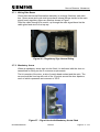
2.3.4 Erecting the Pole
The pole assembly may be completed to the point of having drawn up the cables
and fitted at least the pole cap prior to erection, in which case see Section 2.3.5.
Alternatively, assembly may follow erection in which case go to Section 2.3.6.
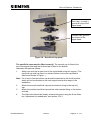
Transport lantern bracket assemblies, pole cap assembly, pole draw rope,
ladders and all necessary tools to the first pole location.
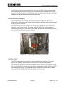
The mounting kit (delivered separately) includes a ‘U’ bolt and two M8 bolts that
are used to attach pole spacers and then the signal head to the pole.
The ‘U’ bolt is fixed in the lower position; attach a nut loosely to one end (to
prevent the bolt being lost inside the pole), feed the other end in through one
hole and out of the other. Remove the nut, place the pole spacer over the bolt
ends and attach firmly to the pole using plain M8 washers and M8 nuts.
The upper pole spacer is held in place with two M8 bolts, washers and nuts that
can be held in place with a hand inside the pole whilst fixing to the pole. These
bolts should be securely tightened.
2.3.5 Wiring Pole prior to erection
Each cable can be fed through the base aperture to the top of the pole using the
draw rope if necessary to pull the cable up.
Unpack and dismantle the pole cap assembly and fit the terminal block assembly
to the pole with the nuts, bolts and washers supplied.
Connect the earth cable from the terminal block assembly to the earth connector
in the pole.
Secure all cable(s) to the slots on the terminal block assembly using the CET
connector(s) and worm drive hose clip(s). Note that a suitable allowance must be
made for the amount of cable at the bottom of the pole.
The pole is now ready for erection. Once this operation is completed, the
excavation at the base of the pole may be back-filled.
Note that Lanterns are not terminated until after the cables have been tested.
On completion of all pole top terminations, the tests described in the Installation
and Testing Handbook (see section 1.3) are to be completed.
2.3.6 Wiring Pole after erection
Each cable can be fed through the base aperture to the top of the pole using the
draw rope if necessary to pull the cable up.
This operation is then repeated for each pole at the intersection.
Unpack and dismantle the pole cap assembly and fit the terminal block assembly
to the pole with the nuts, bolts and washers supplied.
Connect the earth cable from the terminal block assembly to the earth connector
in the pole.
Secure all cable(s) to the slots on the terminal block assembly using the CET
connector(s) and worm drive hose clip(s).
667/HB/30000/000
Issue 24
Page 31 of 143
HELIOS GENERAL HANDBOOK
Measure off wires to length, cut, strip, terminate necessary cores to terminal
block and terminate two cables cores in earthing block for test purposes as
described in Section 2.3.8.
Once this operation is completed, the excavation at the base of the pole may be
back-filled.
Note that lanterns are not terminated until after the cables have been tested.
On completion of all pole top terminations, the tests described in the Installation
and Testing Handbook (see section 1.3) are to be completed.
2.3.7 Neutral Connections General
For the purpose of the following text, for ELV systems the ground return is
considered in the same way as a neutral return for a LV system.
Introduction
Street wiring faults can sometimes affect the display of traffic signals on-street.
Poor connections, for example in pole top termination blocks usually leads to the
failure of signals to illuminate properly which may be detected by lamp
monitoring where this is implemented.
Context
Where common neutral connections are used it is possible for the failure of a
neutral connection to cause unexpected signal displays, where one or more
signals within a given signal head are incorrectly illuminated simultaneously. This
lack of neutral connection is not detectable by the controller because the signal
voltage presented at the controller terminals does not exceed the required
thresholds for conflict or correspondence monitoring.
When incandescent signals are used a cable fault of this type usually causes the
signals to be illuminated at a low level and is not particularly noticeable. For LED
signals however it is possible for the signals to flash, at least at their 'dim' level.
Although the rate of signal flashing is such that they are only typically illuminated
for a very short time, less than the conflict / correspondence time defined in
TR2500, it can be more noticeable than the display seen with incandescent
lamps.
Procedure
Normally this type of fault only affects a single signal head or pole and due to
other signals displaying correctly is unlikely to cause signalisations that could be
considered dangerous, so retrospective action is not essential.
Therefore we are not mandating retrospective action on existing sites, however if
the customer wishes to re-wire then we can do this on a chargeable basis
667/HB/30000/000
Issue 24
Page 32 of 143
HELIOS GENERAL HANDBOOK
However for new LED sites where it is desired to reduce the likelihood of
incorrect displays, particularly involving green signals, it is recommended that
individual neutral returns are used for each green signal. For existing
incandescent sites where LED signals are being now fitted and spare cables
cores are available these may be used to provide additional neutral connections.
2.3.8 Pole Neutral Connections and Terminations (Halogen)
On long neutral runs during Red/Amber, the current can cause large voltage
drops. This contravenes the IEE Regulations which only allow a 2.5% voltage
drop overall. In addition, the voltage drops can affect the operation of the green
voltage monitor and/or lamp monitors. The length of the neutral feeds must not
exceed the length shown below. The number of bulbs is the total number of
bulbs which can be illuminated at any one time, e.g. phase A and phase AB will
both have two bulbs lit during the Red/Amber period. Where two poles are fed on
one cable, the length of cable should be taken as the mid-point between the two
poles.
The cable inside a pole is approximately 3.25 metres. So, for normal runs, the
length of run shown on the STS should be approximately six metres shorter than
the maximum allowable length of cable.
Where a cable run exceeds the figures shown, two cores of the cable can be
used as the neutral feeds, then the distances shown can be increased by a
factor of 1.5.
Number of
Lamps Lit
1
2
3
4
5
6
7
8
9
10
11
12
13
14
15
16
667/HB/30000/000
Current
0.27
0.54
0.81
1.08
1.35
1.62
1.89
2.16
2.43
2.70
2.97
3.24
3.51
3.78
4.05
4.32
Total Length
of Cable
370
185
123
93
74
62
53
46
41
37
34
31
28
26
25
23
Issue 24
Typical Cable
Run on STS
364
179
117
87
68
54
43
40
35
31
28
25
22
20
19
17
Page 33 of 143
HELIOS GENERAL HANDBOOK
Number of
Lamps Lit
17
18
19
20
Current
4.58
4.86
5.13
5.40
Total Length
of Cable
22
21
19
18
Typical Cable
Run on STS
16
15
13
12
If there is a danger of neutral connectors being disconnected it is recommended
that separate neutrals be used for:
1. Signals and green arrows
2. Wait indicators
3. Box Signs, Solar Cell and MVDs
4. Sonalert on Pelican Controllers.
If more than one armoured cable conductor with the same function needs to be
terminated into the post terminal block, they should be connected into one side
of the connector. The other side should be left clear for the connection of lantern
conductors.
2.3.9 Pole Neutral Connections and Terminations for CLS ELV
See 667/DS/20664/048 – Traffic Signal Junction Cabling Design Certification for
ELV Systems - Latest Issue.
2.4 Controller Neutral Connection
Neutral kits are available for the ST800 and ST400 controllers. The part numbers
are 667/1/27068/000 and 667/1/20679/000 (or /001 with terminal block)
respectively. Where these are not available, proceed as described below.
Minimum wire size to be 24/0.2 mm (1.5 sq. mm) and colour to be black for
neutrals. Length required approximately 1.5 metres maximum.
Cut lengths of wire 60 mm long and bare each end for 10 mm.
Starting at the appropriate terminal block insert two separate ends into the block
and screw down tightly. Take each loose end and loop around to the next
position. Continue in this fashion for as many neutral terminal points as are
required. Two lengths of wire approximately 250 mm long (with bare ends for 10
mm) can be used to loop around to other terminal block positions.
Terminal blocks may be used for both neutral looping and phase live output
looping that may require more than the single screw terminal provided. See
Figure . Note that no bare strands should be exposed when the looping is
complete. Consult the appropriate controller installation manual for details of the
terminal blocks designated for such use.
It is important that all of these connections are checked for tightness during
periodic inspections (PI).
667/HB/30000/000
Issue 24
Page 34 of 143
HELIOS GENERAL HANDBOOK
Phase drive
R A G
Controller
neutral
Figure 12 – Wiring of the Neutral Terminal Block
2.5 Helios Bracket Assemblies
There are four types of bracket for Helios:
1. The standard bracket that is used top and bottom on a three aspect case
(667/2/30070/003) and the bottom bracket on the four in-line, two in-line and
single aspect assemblies.
2. A four in line assembly has a long top bracket (667/2/30070/004) and a
standard bottom bracket.
3. A two in line (pedestrian) assembly uses a longer top bracket
(667/2/30070/002) fitted as shown in Figure and a standard bottom bracket.
4. A single aspect assembly uses a one aspect top bracket (667/2/30070/001)
and a standard bottom bracket.
Three-aspect signal heads are generally delivered with the brackets attached.
For a four in line case the long top bracket is attached to the top of the signal
head and the bottom bracket is attached to the separately delivered bottom
aspect.
2.5.1 Extension Bracket Assembly
Signal heads can be mounted away from the pole using extension arms. To
ensure that the arms are mounted the correct way up, the mounting plate on the
arm should be examined. It will be apparent that the lip is longer in one direction
and the longer lip must be mounted toward the top of the pole.
Make up on the ground by laying out the two horizontal arms and attaching the
vertical bar between them using the fixings provided.
Hang the extension bracket on the pole and fix using the nuts provided.
667/HB/30000/000
Issue 24
Page 35 of 143
HELIOS GENERAL HANDBOOK
Add bolts and spacers to the extension bracket on which to hang the signal
head. All bolts should be securely tightened.
Figure 13 – Extension Bracket
Connections from the signal head to the pole are enabled by the use of a
terminal block in the top aspect case.
2.5.2 Side Mounting Bracket
Where signal heads are to be fitted at an angle of rotation greater than 45 , and
also need to be tilted, side mounting brackets (part no. 667/1/30200/058) should
be installed as shown in Figure 14 to assist in final adjustment. This usually only
applies to road traffic signals.
They may also be used to fit an AGD (section 2.34) if required.
Figure 14 – Side mounting bracket
667/HB/30000/000
Issue 24
Page 36 of 143
HELIOS GENERAL HANDBOOK
2.6 Signal Head Arrangement
KEY-May be green aspect,
green arrow, pedestrian
green man/red man or
regulatory sign, e.g. No Left
Turn, No U Turn, etc.
Figure 15 – Example Mounting Arrangements
Figure shows a selection of arrangements, but it is not an exhaustive depiction
of what is possible. A maximum of eight modules may be incorporated on one
assembly, arranged as a four-aspect lantern assembly with two side boxes on
each side.
2.6.1 Sacrificial Caps
Most signal head assemblies are delivered with the sacrificial caps and brackets
fully assembled and attached to the signal head. In those cases where the
assembly has to be made on site, follow the instructions given below.
Sacrificial cap assemblies are fitted to either end of the main signal head. The
assemblies are made up of an end cap, the sacrificial cap, the cap-to-bracket
fitting and an 8 mm Allen bolt. They differ only in the design of the cap; one has a
smooth lower surface and the other has teeth that engage in the end cap.
667/HB/30000/000
Issue 24
Page 37 of 143
HELIOS GENERAL HANDBOOK
Plain cap ( no teeth ),
goes at the top of the
signal head.
Toothed cap, goes at
the bottom of the
signal head.
Figure 16 – Sacrificial Cap parts
The sacrificial caps must be fitted correctly. The smooth cap is fitted to the
top of the signal head and the toothed cap is fitted to the bottom.
Assemble the parts as follows:
1.
Attach one end cap at each end of the signal head using five screws. (The
sacrificial cap end cap fixes in a similar position to the end cap fitted to
side boxes shown in Figure .)
Note: For a four-in-line the bottom cap should be attached to the fourth module,
which will not be attached to the main signal head at this stage of the
installation.
2.
Attach the smooth sacrificial cap and one bracket fixing to the top end
cap.
3.
Attach the toothed sacrificial cap and the other bracket fixing to the bottom
end cap.
4.
The Allen bolts should be loosely screwed into place using the 8 mm Allen
key. Adjustment is needed later; see section 2.36.1.
667/HB/30000/000
Issue 24
Page 38 of 143
HELIOS GENERAL HANDBOOK
Figure 17 – Sacrificial Cap assembly
2.6.2 Brackets
Most signal head assemblies are delivered to site with the sacrificial caps and
brackets ready attached to the signal head. In those cases where the assembly
has to be made on site, follow the instructions given below.
The brackets should be attached to the signal head-to-bracket fixings at both
ends of the signal head, using the M10 screws and bolts supplied. Do not fully
tighten the screws, as adjustment is required later. See section 2.36.1.
2.6.3 Remove Doors
Two sliding clips on either side fix the door to its Aspect. When signal heads and
side boxes are delivered, the doors are fitted.
To remove a door, open all four clips and lift the door off. If necessary, use the
point of a screwdriver as shown in Figure to push open the door clips. A Teflonbased or similar dry type lubricant may be used to lubricate the clips.
Figure 18 – Using a screwdriver to open the door clip
Leave the lens and reflector in place on the rear of the door and unclip the bulb
holder from the rear of the reflector.
667/HB/30000/000
Issue 24
Page 39 of 143
HELIOS GENERAL HANDBOOK
Figure shows a door clip in the half-open position with the door sitting above and
unconnected. The door ‘peg’ is held in place by the door clip.
Figure 19 – Door clip detail
2.6.4 Green Arrow (Halogen), CLS with LMF, CLS (NLM) and CLS ELV
The green arrow optic includes a metal mask (667/2/30074/101) as shown in
Figure . This module is delivered with the mask positioned either vertically
(straight ahead) or horizontally for left- or right-turn. The mask has castlations
that fit into indentations in the reflector/lens retaining ring enabling it to point in
any one of 16 directions, depending on individual site requirements.
Figure 20 – Green Arrow mask
Any adjustment to the orientation of the green arrow should be carried out with
the optic door removed from its aspect and placed on a flat surface to help in
positioning the lens seal.
The Type B CLS ELV module is designed such that the Arrow Mask can be
replaced / adjusted with the door ring in situ. This removes the potential of
disturbing the lens seal as the clear lens is retained by the door ring.
667/HB/30000/000
Issue 24
Page 40 of 143
HELIOS GENERAL HANDBOOK
Helios (Halogen)
To alter the position of the mask, unscrew the reflector from the rear of the door
and remove it. Tip the mask out from behind the lens (replacing the lens in its
original position if necessary) and replace in the position required.
Make sure that the two seals (lens/door and lens/reflector) are in place and
screw the reflector back into position. See section 4.2.15 and Figure for details.
CLS with LMF, CLS (NLM) and CLS ELV Type A
To alter the position of the mask, remove the CLS unit by –
a) Futurit CLS - Removing the two CLS retaining clips and release it from the
remaining clips in the lens retaining ring and then unscrew the lens retaining
ring from the rear of the door and remove it.
b) Dialight CLS – Remove the 4 screws holding the unit to the rear of the door.
Tip the mask out from behind the lens and replace it in the position required in
the retaining ring.
Replace the lens back in its original position on a) Futurit CLS - the retaining ring, and make sure that the lens/door seal is in
place. Place the door over the lens, tip the assembly over and screw the
retaining ring back into position on the door. Replace the CLS unit into the
retaining clips in the lens retaining ring and then replace the retaining clips
which hold the CLS in position.
b) Dialight CLS – the CLS unit and make sure that the lens/door seal is in place.
Place the door over the lens, tip the assembly over and screw the CLS unit
back into position on the door.
CLS ELV Type B
To alter the position of the mask–
a) Gently press the anti-rotation clip at the bottom of the CLS enclosure using a
small screwdriver or other suitable tool (see Figure 21).
667/HB/30000/000
Issue 24
Page 41 of 143
HELIOS GENERAL HANDBOOK
Figure 21 CLS ELV Type B Anti-rotation Clip
b) Rotate the enclosure body anticlockwise and withdraw the enclosure from the
door ring.
c) Insert or adjust the mask as required.
Figure 22 CLS ELV Arrow Mask
d) Re-fit the enclosure to the door by inserting and rotating clockwise. Ensure
that the anti-rotation clip has engaged and that the enclosure cannot be
rotated anti-clockwise.
2.6.5 Green Arrow (LED and LED (NLM))
There are two variants of the green arrow LED and LED (NLM); up and left/right.
If any other direction is needed, the fully populated green LED or LED (NLM)
must be used.
The green arrow metal mask (667/2/30074/101) is used with LED and LED
(NLM) PCBs to prevent any shadowing from the board electronics, and to hide
the superfluous LEDs on the left/right arrow or fully populated PCB.
Any adjustment to the orientation of the green arrow mask should be carried out
on a flat surface to help in positioning the lens seal.
To alter the position of the mask, unscrew the retaining ring from the rear of the
door and remove it. Tip the mask out from behind the lens and place it in the
position required in the retaining ring. Replace the lens back in its original
position on the retaining ring, and make sure that the lens/door seal is in place.
Place the door over the lens, tip the assembly over and screw the retaining ring
back into position on the door.
Secure the door, tightening the anti-vandal screws if supplied.
667/HB/30000/000
Issue 24
Page 42 of 143
HELIOS GENERAL HANDBOOK
2.6.6 Equestrian (Halogen, CLS with LMF, CLS (NLM), CLS ELV, LED and LED
(NLM))
Lens are available for displaying equestrian figures. These lens have the
equestrian figure ‘silk-screened’ on to them.
a) Red and Green Equestrian Lens for the Halogen Helios options
667/1/30200/399 – Red Equestrian (Lamp) Lens
667/1/30200/398 – Green Equestrian (Lamp) Lens
b) Clear Equestrian Lens for the LED and LED (NLM) Helios options
667/1/30200/397 – Clear Equestrian Lens (LED) Lens.
This lens is used in front of Red and Green LED and LED (NLM) PCB
option.
c) Clear Equestrian Lens for the CLS with LMF, CLS (NLM) and CLS
(ELV) Helios options 667/1/31500/397 – Clear Equestrian Lens (LED) Lens.
This lens is used in front of Red and Green CLS with LMF, CLS (NLM)
and CLS (ELV) units.
2.6.7 Four in Line
A four in line configuration is delivered with three aspects assembled and the
fourth in separate packaging. The bottom bracket will be attached to the fourth
aspect.
The fourth aspect should first have the O ring fitted (included with the mounting
kit) to seal the join between the boxes. It should then be clipped in place and
secured using the two M5 x 45 mm screws supplied in the outer fitting positions
(see Figure and Figure ).
2.7 Side Boxes
Side boxes are supplied with all the necessary fixings to fit them to the signal
head. One metal plate should be screwed vertically between the units; the other
fits horizontally for extra support. See Figure and Figure for fixing details. There
is a conduit supplied to run the cables through.
The holes for the conduit should be drilled using an 18 mm or 20 mm drill bit in
the forward drill start position on the signal head as shown in Figure with a
corresponding hole in the side box. Figure shows the conduit fitting from inside
an aspect case.
If two side boxes are to be fitted on one side, they should be connected together
in the same way as the aspect boxes (see section 2.6.7) before being fitted to
the main signal head.
667/HB/30000/000
Issue 24
Page 43 of 143
HELIOS GENERAL HANDBOOK
Figure 23 – Side box showing fixing plates and conduit
Figure 24 – Side box fitted on right of main signal head
Both ends of any side fittings should have end caps fitted as shown in Figure .
There is an O ring supplied to seal the fittings to the body that should be placed
in the groove inside the end cap.
Figure 25 – End cap fitted to side box
667/HB/30000/000
Issue 24
Page 44 of 143
HELIOS GENERAL HANDBOOK
2.7.1 Wiring Side Boxes
Check that the internal illumination assembly is correctly fitted into each side
box. Green arrow and cycle side boxes have internal fittings similar to the main
signal head; regulatory signs are fitted as shown in Figure .
Feed the cable through the conduit, up through the main signal head via the
cable gland and wire to the top cap.
Figure 26 – Regulatory Sign internal fitting
2.7.2 Mandatory Arrow
Where a mandatory arrow sign is to be fitted, it is delivered with the door unassembled for fitting on site to customer requirements.
The kit consists of the door, a strip of mastic bead sealant and the optic. The
arrow should be lined up with one of the 16 points around the door aperture,
each of which represents an increment of 22.5 .
Figure 27 – Signal Head with Mandatory Arrow fitted
667/HB/30000/000
Issue 24
Page 45 of 143
HELIOS GENERAL HANDBOOK
Clean the door aperture and outside of the lens carefully and ensure that both
are completely dry before fitting the lens. Place the strip of sealant around the
inside of the door aperture, carefully align the lens and press both parts together.
Remove any surplus seal from the face of the lens.
2.8 Transformers (Halogen)
The transformers will normally be factory fitted before delivery. The usual
position is in the bottom right corner of the module, although they may be placed
in any of the four corners.
If the transformer is to be fitted in one of the upper positions, four screws are
required, one in each corner. For lower position fitting, only two screws are
needed to hold the unit to the floor of the case, as the rear of the transformer fits
into the retaining slots as shown in Figure .
Figure 28 – Transformer fitted to floor of case
2.9 PSUs (LED)
The PSU assembly will normally be factory fitted before delivery. The usual
position is centrally near the floor of the case, one in each LED aspect.
The assembly consists of a metal backplate with an inductor tie-wrapped to one
side, a metal PSU cover with an earth point and keyhole fixings holding the PSU
and associated wiring. The backplate may be fitted with the inductor on either
side; the PSU is always fitted with the earth point at the top.
667/HB/30000/000
Issue 24
Page 46 of 143
HELIOS GENERAL HANDBOOK
Figure 29 – PSU assembly fitted into case
2.10 Transformers LED (NLM)
The transformers will normally be factory fitted before delivery. The usual
position is in the bottom right corner of the module, although they may be placed
in any of the four corners.
If the transformer is to be fitted in one of the upper positions, four screws are
required, one in each corner. For lower position fitting, only two screws are
needed to hold the unit to the floor of the case, as the rear of the transformer fits
into the retaining slots.
Figure 30 – LED (NLM) Transformer Fitted to Aspect
667/HB/30000/000
Issue 24
Page 47 of 143
HELIOS GENERAL HANDBOOK
2.11 CLS Unit
The CLS units will normally be factory fitted into the appropriate door before
delivery. There are three variants of the CLS unit
a) Red CLS unit
- 667/7/28584/100
b) Amber CLS unit - 667/7/28584/101
c) Green CLS unit - 667/7/28584/102
The CLS unit is obtained from 2 manufacturers, Futurit and Dialight.
The Futurit CLS unit is positioned into the lens retaining ring and held in place
with two CLS retaining clips (667/2/31501/000). The lens retaining ring and CLS
retaining clips are fitted into the door with four screws.
The Dialight CLS unit has the lens retaining ring built into the unit and is fitted to
the aspect door with four screws.
CLS Retaining Clips
Figure 31 – Futurit CLS Unit
667/HB/30000/000
Issue 24
Page 48 of 143
HELIOS GENERAL HANDBOOK
Figure 32 – Dialight CLS Unit
2.12 CLS ELV Units
The CLS units will normally be factory fitted into the appropriate door before
delivery.
There are two different types of CLS ELV units, each type has a Red, Amber and
a Green variant.
CLS ELV Type A:
Red
-
667/7/28586/100
Amber
-
667/7/28586/101
Green
-
667/7/28586/102
Red
-
667/1/46700/100
Amber
-
667/1/46700/101
Green
-
667/1/46700/102
CLS ELV Type B:
The CLS ELV Type A unit has the lens retaining ring built into the unit and is
fitted to the aspect door with four screws.
The CLS ELV Type B unit has a separate retaining ring which is secured to the
door with four screws. The aspect body attaches to the retaining ring by a simple
twist fit mechanism.
667/HB/30000/000
Issue 24
Page 49 of 143
HELIOS GENERAL HANDBOOK
2.13 CLS ELV Type B Transformer Placement
If CLS ELV Type B units are to be retro-fitted to an existing installation it may be
necessary to relocate transformers fitted within the signal head enclosure to
avoid a clash with the aspect enclosure body.
Lamp transformers tend to offer sufficient clearance, however 24V transformers
with top mounted fused terminal blocks (as used for AGD units) must be
mounted on the rear of the signal head enclosure NOT on the bottom (see
Figure 33).
Transformer mounting
points
Figure 33 Transformer mounting points
2.14 Lamp Monitoring Unit (LMF)
The LMF units will normally be factory fitted into the appropriate aspect body
before delivery. The are two variants of the LMF unit
a) LMF for Red Aspect
- 667/1/31180/230R
b) LMF for Amber or Green Aspect
- 667/1/31180/230AG
The two pin plug from the CLS unit and the two pin mains socket from the
controller output are fitted into the LMF Unit.
Note the Mains Input Wiring is formed so as to prevent any water ingress from
the cables dropping in to the LMF Unit.
667/HB/30000/000
Issue 24
Page 50 of 143
HELIOS GENERAL HANDBOOK
Note that the Mains wiring to other LMF Units is tied to the LMF chassis with two
Pushbutton Ties which prevents any heat from the LMF unit from damaging any
of the cable forms.
CLS Unit
Pushbutton
Cable Ties
LMF Mains
Input Wiring
LMF Unit
Figure 34 – CLS with LMF
2.15 ELV TRAM Indicator
The TRAM indicator should only be replaced as a complete module. The
maintenance spares should always be fully equipped modules but the originally
supplied equipment may be sub equipped. The TRAM indicator uses the same
LED driver module as other Helios ELV optics so is compatible with the
ST900ELV lamp monitoring. Care should be taken when removing the and
refitting the unit to not tram the multi-way cable and not to unscrew fixings that
hold the module together.
Do not undo this nut
Access to screws in keyhole
slots through these cut outs
Internal Chassis Plate
Figure 35 – TRAM Indicator with door open
667/HB/30000/000
Issue 24
Page 51 of 143
HELIOS GENERAL HANDBOOK
Keyhole slot
Molex connector
Figure 36 – TRAM Indicator rear view showing Keyhole slots
To remove the Tram indicator from its housing:
The Tram indicator is a complete module and must be replaced as a complete
assembly. The LED and power supply assembly is fitted into a standard Helios
aspect box. This assembly remains in the rear part of the box when the door/lens
assembly is opened. Care must be exercised whilst the door lens assembly
is open as the LED “dots” are extremely bright and may dazzle the viewer.
The assembly is kept in the rear part of the box by screws attaching it to the rear
of the box. A screwdriver with a 150mm crosshead blade is required to reach the
screws. To aid replacement the fixings are located in keyhole slots. Once the
screws are slackened a few turns the assembly can be lifted and withdrawn from
the box. Once the assembly is clear of the box the 12 way Molex connector can
be unplugged. The Molex connector is a tight fit and there are release leavers
that must be squeezed to enable the connector to part. It is essential that the
operative is stable with both hands free when attempting this operation. Re-fitting
is the reverse of removal. The operative must ensure that the cable does not
become trapped when refitting the assembly. The entire assembly can then be
returned for repair. Although there are 3 variants of the TRAM indicator module
only the fully equipped version will be kept as a spare. The faulty unit will be
upgraded to the fully equipped version as part of the repair process. Dismantling
of the indicator module must not be attempted. Under no circumstances should
the 4 nuts on the front of the module be undone as this will result in the module
falling apart. This could result in short circuits and the signals extinguishing. It
could also result in damage to the LED’s and the driver modules.
667/HB/30000/000
Issue 24
Page 52 of 143
HELIOS GENERAL HANDBOOK
Do not undo this nut
Keyhole slot
Individual LED dot LENS
Figure 37 – TRAM Indicator showing keyhole slot from the front
2.16 Terminal Blocks
Fixing positions have been provided for terminal blocks, which are generally only
fitted in aspects where an extension bracket has been used. Figure shows a
terminal block fitted in one of the positions provided and Figure gives all the
possible fixing positions.
2.17 Bridge Rectifier
See Figure and Figure for the fixing position.
Note: if the cable P-clip is fitted in this position, either fit the bridge to another
unused pillar position or move the P-clip.
Figure 38 – Bridge Rectifier
2.18 Cable Gland
The cable gland is normally fitted in the knockout on the back of the top (red)
aspect, but it may be fitted where required, with the following provisos:
1. For a four-in-line assembly the gland must be fitted to the second box.
667/HB/30000/000
Issue 24
Page 53 of 143
HELIOS GENERAL HANDBOOK
2. Side mounted signals may have the cable gland fitted in one of the three
recesses in the side of the module.
3. Pedestrian signals may have the cable gland fitted in any position to reduce
the length of the conduit.
Wherever the gland is fitted, consideration should be given to the length of the
transformer/PSU wires and the amount of conduit tubing between the signal
head and the pole. A long length of tubing is unsightly and should be avoided
wherever possible.
To fit the conduit tubing, screw the conduit adapter into the cable gland. Feed the
locking ring onto the conduit tube and push the tubing firmly onto the end of the
adapter. Seal in place with the locking ring. Note that the tubing does not form
part of the signal head assembly, but should be kept in quantity by installers and
cut to fit as required.
2.19 Hoods
The signal is normally supplied with Helios moulded primary or secondary hoods,
but will also accommodate a wide range of hoods used with the previous Mellor
style signals if required, including most louvred and tunnelled hoods.
The new moulded hood is fitted with insertion slots for accurate positioning and
is attached using fir-tree clips. See Figure for details. The clips are just pushed
in to hold the hood in place.
Figure 39 – Standard Hood fitting
The moulded hoods may be fitted straight or turned up to 90 without
modification. If, for any reason, a hood needs to be attached at more than 90 to
the vertical, new holes will need to be drilled in the hood. Also, hoods used on
previous signals may need on site drilling to fit Helios. See section 2.19.1 for
details.
667/HB/30000/000
Issue 24
Page 54 of 143
HELIOS GENERAL HANDBOOK
Figure 40 – Angled Hood fitting
An optional Pedestrian Aspect Hood is available. This hood is supplied with
predrilled fixing holes but is of a non formed construction. The hood is fitted to
the aspect using fir-tree clips.
2.19.1 Drilling Hoods
To fit hoods that do not have fixing holes that align with those on the Helios door,
including louvred and tunnel hoods, the fitting positions have to be drilled using a
6 mm drill bit. A moulded hood fitted at more than 90 also needs to be drilled.
Correctly position the hood to be drilled on the Helios door and then mark the
appropriate positions that require drilling. Remove the hood from the door and
drill the marked fixing hole positions.
Where metal hoods (which may be heavy) have been drilled, 5 mm bolts, metal
rivets or taptite screws may be more appropriate fixings than the plastic fir-tree
clips.
2.20 Solar Cell
A solar cell is fitted when the customer requires the signals on the intersection to
be dimmed at night.
It is mounted on the top of a 3-aspect case, as shown in Figure where it will
receive a non-interrupted northern light.
667/HB/30000/000
Issue 24
Page 55 of 143
HELIOS GENERAL HANDBOOK
Figure 41 – Solar Cell
The solar cell used is a Royce Thompson Electric Ltd type RTE/P5 (55 Lux)
(STCL part number 506/4/97891/000) or equivalent, which plugs into a Rotaloc
Socket. The cell is mounted on the top of the 3-aspect case, through a 20 mm
diameter hole, drilled using one of the two central guide indents on top of the
case. Around the central indent are eight other drill start points, four of which
should be used to secure the solar cell to the case, pointing north, using nuts
and bolts and the “cork” washer. See Figure .
The three terminals on the socket are connected as follows:
Socket terminal L – Live
Socket terminal N – Neutral
Socket terminal Lo – to Controller dim input
Each terminal is wired to the terminal block mounted on the top of the pole by
24/0.2 mm wire using the following colours:
Line – Brown
Neutral – Blue
Load – White
The solar switch is connected to its socket by locating the terminals in their slots
and pushing down, then twisting the unit clockwise when looking down on the
socket. This twist completes the circuit and, if not done correctly, the solar switch
will not function.
During daylight the solar switch should give the signal bright condition. To test it,
cover the unit for approximately one minute and check that the signals go to the
dim condition. Uncovering the unit should then result in the signals going to the
bright condition after approximately one minute.
667/HB/30000/000
Issue 24
Page 56 of 143
HELIOS GENERAL HANDBOOK
2.21 Pedestrian Push Button (Mk 1)
There are two variants of push button units currently in use in the United
Kingdom:
Standard push button with no Sonalert (667/1/01478/000) (2 man)
Pelican push button fitted with Sonalert (667/1/01478/001) (3 man)
Figure 42 – Pedestrian push button unit
2.21.1 Optional Wiring Kits for Pedestrian Pushbutton (Mk 1)
The pedestrian push button unit comes complete with its fixing kit. Two optional
wiring kits (667/1/26942/000) and (998/4/88324/000) are available for connection
to the terminal block inside the PBU provided.
The connections to these wires are as follows:
Wire Colour for
667/1/26942/000
Green/Yellow
Wire Colour for
998/4/88324/000
Green/Yellow
Signal Name
Orange
Orange
Push button 1
Orange
White
Push button 2
667/HB/30000/000
Issue 24
Earth
Page 57 of 143
HELIOS GENERAL HANDBOOK
Red
Red
Aud. Signal +
Black
Black
Aud. Signal -
Blue
Blue
Wait Ind N
Brown
Brown
Wait Ind. L
Violet *¹
Green*²
Tactile motor +
Yellow *¹
Yellow*²
Tactile motor -
The wires within the Pedestrian push button should be arranged and cable tied
so that the wiring cannot touch the push button micro-switch housing.
Each wire is 4 metres long and connects to the terminal block in the pole cap
assembly.
(*¹ NOTE – If the Optional Audible Supply Kit (667/1/27006/000) is fitted wire
Violet to Audio 2 and Yellow to Aud. Signal – )
(*² NOTE – If the Optional Audible Supply Kit (998/4/88324/000) is fitted, wire
Green to Audio 2 and Yellow to Aud. Signal –)
(Ensure that the wiring at the controller is to 667/GA/27006/000 Sht 2 Issue 3))
The unit fastens to the pole using the ‘U’ bolt provided.
When installing a pushbutton box, the centre of the pushbutton should be
between 1.0m – 1.1m above the footway level.
2.22 L.E.D. Wait Box (Mk 1)
There are four variants of the 48 Volt L.E.D. Wait Box available for use in the
United Kingdom. These are –
Pedestrian Pushbutton Unit without Audible/No Lamp Monitoring 667/1/30210/000
Pelican Pushbutton Unit with Audible/No Lamp Monitoring –
667/1/30210/011
Pelican Pushbutton Unit without Audible/No Lamp Monitoring –
667/1/30210/001
Toucan Pushbutton Unit without Audible/No Lamp Monitoring –
667/1/30210/002
667/HB/30000/000
Issue 24
Page 58 of 143
HELIOS GENERAL HANDBOOK
Figure 43 – LED Wait Box
The L.E.D. Wait Box comes complete with its fixing kit.
The unit fastens to the pole using the ‘U’ bolt provided.
When installing a pushbutton box, the centre of the pushbutton should be
between 1.0m – 1.1m above the footway level.
2.22.1 Optional Wiring Kits for L.E.D. Wait Box (Mk 1)
Two wiring kits (667/1/26942/000) and (998/4/88324/000) are available for
connection to the terminal block inside the LED Wait Box to the terminal block in
the pole cap assembly. (Note that each wire is 4 metres long).
The connections to these wires are as follows:
Wire Colour for
667/1/26942/000
Green/Yellow
Orange
Orange
Red
Black
Blue
Brown
Violet *¹
Yellow *¹
667/HB/30000/000
Wire Colour for
998/4/88324/000
Green/Yellow
Orange
White
Red
Black
Blue
Brown
Green*²
Yellow*²
Issue 24
Signal Name
Earth
Push button 1
Push button 2
Aud. Signal +
Aud. Signal Wait Ind N
Wait Ind. L
Tactile motor +
Tactile motor -
Page 59 of 143
HELIOS GENERAL HANDBOOK
(*¹ NOTE – If the Optional Audible Supply Kit (667/1/27006/000) is fitted, wire
Violet to Audio 2 and Yellow to Audio 0v Common)
(*² NOTE – If the Optional Audible Supply Kit (998/4/88324/000) is fitted, wire
Green to Audio 2 and Yellow to Audio 0v Common)
(Ensure that the wiring at the controller is to 667/GA/27006/000 Sht 2 Issue 3))
Optional Radix Tactile Equipment (667/7/17390/000) is available for all variants
of L.E.D. Wait Box.
2.22.2 L.E.D. Wait Box Doors (Mk 1)
All variants come with a Door Assembly which contains the following items
a) A PCB which contains all the display LEDs arranged to display the
‘WAIT’ output and the LED control circuitry. (667/1/30211/000)
b) A vandal resistant pushbutton. This button has no moving parts and is
touch sensitive. (667/1/30210/505)
c) A polycarbonate front panel, the type which is dependant on the LED
Wait Box variant. (see 667/2/26302/ETC)
The following Door Assemblies are available –
Pedestrian Door
– (667/1/30210/200)
Pelican Door
– (667/1/30210/205)
Toucan Door
– (667/1/30210/210)
Equestrian Door
– (667/1/30210/215)
667/HB/30000/000
Issue 24
Page 60 of 143
HELIOS GENERAL HANDBOOK
Pushbutton Assembly
‘WAIT’ PCB Assembly
Figure 44 – LED Wait Box Door Assembly (Mk 1)
2.23 Nearside Signal and Demand Unit (Mk 1)
There are three variants of the Nearside Signal and Demand Unit, which are dual
housed, for use in UK Puffin, Toucan and Equestrian Crossing applications.
The Nearside Signal is illuminated using either Red or Green LEDs, whilst the
Demand unit uses a Touch Sensitive switch around which is illuminated by Red
LEDs when a Demand is registered.
The UK Variants are –
Puffin Nearside Signal and Demand Unit
– 667/1/30670/000
Toucan Nearside Signal and Demand Unit
– 667/1/30670/001
Equestrian Nearside Signal and Demand Unit – 667/1/30670/002
Each Nearside Signal Unit and Demand Unit comes complete with its fixing kit.
Each unit fastens to the Signal Pole using the ‘U’ bolt provided.
When installing the Nearside Signal and Demand Unit the following must be
observed –
a) Centre of the Demand Unit Push button must be 1.0m – 1.1m above
the footway level.
b) The distance between the bottom edge on the Demand Unit and the
top edge of the Nearside Signal Unit must be less than 550mm, but
remember to leave sufficient room between the two units to allow the
removal of the Nearside Unit Door.
Optional Audible Supply Kits (667/1/27006/000) and Optional Radix Tactile
Equipment (667/7/17390/048) are available and will normally be fitted into the
Demand Unit.
667/HB/30000/000
Issue 24
Page 61 of 143
HELIOS GENERAL HANDBOOK
Figure 45 – Toucan Nearside Signal and Demand Unit
2.23.1 Nearside Signal Unit (Mk 1)
The three variants of Nearside Signal come with a door assembly which contain
the following items –
a) a PCB which contains all the Display Red LEDs arranged to illuminate
either the Red Man (Puffin), Red Man and Red Cycle(Toucan) or a Red
Horse (Equestrian).
b) a PCB which contains all the Display Green LEDs arranged to
illuminate either the Green Man (Puffin), Green Man and Green
Cycle (Toucan) or a Green Horse (Equestrian).
c) a front panel, the type which is dependant on the Nearside Signal
667/2/30690/000 – Puffin
667/2/30690/001 – Toucan
667/2/30690/002 – Equestrian
The following are the Nearside units that are available –
Puffin Signal Unit
- 667/1/30675/000
Toucan Signal Unit
- 667/1/30675/001
Equestrian Signal Unit
- 667/1/30675/002
The following are the Door Assemblies that are available –
Puffin Door
- 667/1/30686/000
Toucan Door
- 667/1/30686/001
Equestrian Door
- 667/1/30686/002
667/HB/30000/000
Issue 24
Page 62 of 143
HELIOS GENERAL HANDBOOK
Figure 46 – Nearside Signal - Shows the Two PCBs (Mk 1)
Figure 47 – Red Man PCB from Puffin Nearside Unit (Mk 1)
667/HB/30000/000
Issue 24
Page 63 of 143
HELIOS GENERAL HANDBOOK
Red Man/Cycle/Equestrian PCB
Position of Red
Man/Cycle/Equestrian PCB
Position of Green
Man/Cycle/Equestrian PCB
Figure 48 – Nearside Signal Shown with Red Man/Cycle/Equestrian PCB
Removed (Mk 1)
The Following PCB variants are available for the Nearside Signal –
1) Green Puffin
- 667/1/30695/001
2) Red Puffin
- 667/1/30695/002
3) Green Toucan
- 667/1/30695/003
4) Red Toucan
- 667/1/30695/004
5) Green Equestrian
- 667/1/30695/005
6) Red Equestrian
- 667/1/30695/006
2.23.2 Demand Unit (Mk 1)
The Demand Unit (667/1/30675/100) comes with a Door (667/1/30685/000) that
contains the following –
a) a PCB which contains all the LEDs arranged in a circle around the
push button which illuminate when a Pedestrian Demand is Registered
(667/1/30680/000).
b) A vandal resistant pushbutton. This button has no moving parts and is
touch sensitive (667/1/30210/505).
c) A polycarbonate front panel (667/2/30676/000).
667/HB/30000/000
Issue 24
Page 64 of 143
HELIOS GENERAL HANDBOOK
Vandal Resistant Pushbutton
LED PCB
Figure 49 – Demand Unit
2.23.3 Optional Wiring Kits for Nearside Signal Unit and Demand Unit (Mk 1)
Two wiring kits (667/1/26942/000) and (998/4/88324/000) are available for
connection to the terminal block/s inside the Nearside Signal Unit and Demand
Unit to the terminal blocks in the pole cap assembly. (Note that each wire is 4
metres long).
Note – a second terminal block requires fitting into the Demand Unit at the Right
Hand Side of the Unit if 2 optional Audible Supply Kits (667/1/27006/000) are
fitted.
The connections for these wires are as follows –
Wire Colour for Wire Colour for Signal Name
667/1/26942/000 667/4/88324/000 Connection Nearside Unit
Green/Yellow
667/HB/30000/000
Green/Yellow
TB1.6 – Earth
Issue 24
Signal Name
Connection - Demand
Unit
TB2 - Earth Connector
Page 65 of 143
HELIOS GENERAL HANDBOOK
Orange
Orange
-
TB1.5 - Push Button +
Orange
White
-
TB1.6 - Push Button -
Red
Red
TB1.1 - RED 48VAC1
TB1.3 - Audio 1 *¹
Black
Black
TB1.2 - RED 40VAC2
TB1.4 - Audio 2 *¹
Blue
Blue
TB1.4 - GREEN
48VAC2
TB1.2 - 48v RET
Brown
Brown
TB1.3 - GREEN
48VAC1
TB1.1 - 48v
Violet
Green
-
Wire Direct to Tactile
Motor + *¹
Yellow
Yellow
-
Wire Direct to Tactile
Motor - *¹
*¹ NOTE – If the Optional Audio Kit (667/1/27006/000) is fitted wire as follows –
a) When using wiring kit 667/1/26942/000
i) Fit an extra terminal block TB2 (703/4/98500/016) to the Right
Hand side Terminal Block position using screws
999/4/03302/012
ii) Wire Red to TB3.1 (Audio 1)
Wire Black to TB3.2 (Audio Sig -)
Wire Yellow to TB3.2 (Audio Sig -)
Wire Violet to TB3.3 (Audio 2)
b) When using wiring kit 998/4/88324/000
i) Fit an extra terminal block TB2 (703/4/98500/016) to the Right
Hand side Terminal Block position using screws
999/4/03302/012
ii) Wire Red to TB3.1 (Audio 1)
Wire Black to TB3.2 (Audio Sig -)
Wire Yellow to TB3.2 (Audio Sig -)
Wire Green to TB3.3 (Audio 2)
(Ensure that the wiring at the controller is to 667/GA/27006/000 Sht2 Issue 3)
2.24
Nearside Mk2 Range of units
The next sections detail the new Nearside Mk2 range of Wait Indicator, Nearside
Demand and Nearside Signal housings. These provide a new contemporary
design that is both aesthetically pleasing and able to provide product
configuration that meet all of the latest customer needs & requirements whilst
reducing manufacturing costs.
667/HB/30000/000
Issue 24
Page 66 of 143
HELIOS GENERAL HANDBOOK
2.25
Nearside Mk2/Pedestrian Wait Mk2 Pole drilling positions
Figure 50: Drilling guide for Nearside and Pedestrian WAIT range
667/HB/30000/000
Issue 24
Page 67 of 143
HELIOS GENERAL HANDBOOK
2.26
Installation of Nearside and WAIT Mk2 fixing kits to pole
DEMAND, SIGNAL
AND WAIT U-BOLTS
CAN BE INSTALLED
THROUGH FIXING
HOLES BUT
COMBINED UBOLTS MUST BE
FITTED THROUGH
GLAND HOLE.
Figure 51: U-bolt and cable gland installation (Mk2)
667/HB/30000/000
Issue 24
Page 68 of 143
HELIOS GENERAL HANDBOOK
2.27
Installation of WAIT, Demand, Signal and Combined Mk2 units to pole
Figure 52: Mounting of Nearside/Pedestrian WAIT units to Pole.
Typical to all assemblies, Combined unit shown.
667/HB/30000/000
Issue 24
Page 69 of 143
HELIOS GENERAL HANDBOOK
2.28
Standard Wait Mk2 Indicator Units
Figure 53 - Standard Wait Mk2 Indicator unit
There are four main variants of Standard Wait Indicator units (with Mechanical
Switch) available for use in the United Kingdom:
Pedestrian WAIT push button without Audio (667/1/33603/010)
Pelican WAIT push button without Audio (667/1/33603/011)
Equestrian WAIT push button without Audio (667/1/33603/012)
Toucan WAIT push button without Audio (667/1/33603/013)
667/HB/30000/000
Issue 24
Page 70 of 143
HELIOS GENERAL HANDBOOK
2.28.1 Terminal Block Layout for STD Wait Mk2 Indicator units
Shown below are the diagrams of the terminal block assembly used within both
of the Nearside Mk2 STD Wait Indicator units
2.29
LED Wait Mk2 Indicator Units
There are four variants of the 48 Volt L.E.D. Wait Box (with Mechanical switch)
available for use in the United Kingdom. These are –
Pedestrian Pushbutton Unit without Audible - 667/1/33602/010
Pelican Pushbutton Unit without Audible - 667/1/33602/011
Toucan Pushbutton Unit without Audible - 667/1/33602/012
Equestrian Pushbutton Unit without Audible - 667/1/33602/013
667/HB/30000/000
Issue 24
Page 71 of 143
HELIOS GENERAL HANDBOOK
Figure 54 - LED Mk2 Wait Box
The L.E.D. Wait Box comes complete with its fixing kit. The unit fastens to the
pole using the ‘U’ bolt provided. When installing a pushbutton box, the centre of
the pushbutton should be between 1.0m – 1.1m above the footway level.
2.29.1 Terminal Block Layout for LED Wait Mk2 Indicator units
Shown below are the diagrams of the terminal block assembly used within both
of the Nearside Mk2 LED Wait Indicator units
667/HB/30000/000
Issue 24
Page 72 of 143
HELIOS GENERAL HANDBOOK
2.30
CLS Wait
Two versions of CLS Wait are available; a retrofit solution and a production
replacement for the existing LED Wait.
Both versions offer the benefit of CLS technology and the possibility of lamp
monitoring depending on the controller type. Table 1 shows the lamp monitoring
options.
Controller
Unmonitored
Lamp Monitoring possible
ST700
Yes
No
ST750
Yes
No
ST750 ELV
Yes
Yes
ST800
Yes
No
ST800 LED
Yes
Yes1
ST900 LV
Yes
No
ST900 LED
Yes
No2
ST900 ELV
Yes
Yes
Table 1 CLS Wait Lamp Monitoring Options
1.
Lamp monitoring is possible however the ST800 Controller firmware
needs to be 667/TZ/12800/000 “PB800” issue 31 or later and configuration
changes may be necessary.
2.
Lamp monitoring is currently not possible with the ST900 LED. This
feature may be provided in the future by means of a firmware update. Please
contact Siemens Traffic Solutions sales department for further details.
Warning: The CLS Wait is an ELV device designed for connection to 48V
systems. If the unit is to be used with an LV controller it will be necessary to fit a
Wait Drive Transformer Kit 667/1/21029/001. Failure to do so will result in the
permanent damage to the unit and possible damage to the controller
2.30.1 CLS Wait Retrofit
The CLS Wait Retrofit kit is designed to allow the upgrade of existing MK1 and
MK2 and Peek 48V incandescant Wait units to CLS technology.
Installation and maintenance details can be found in 667-CI-47700-ETC.
The following parts may be used during the retrofit process, but see 667-CI47700-ETC for more information:
667 /1/47711/000 CLS Wait Retrofit kit
667/HB/30000/000
Issue 24
Page 73 of 143
HELIOS GENERAL HANDBOOK
667 /1/47701/000 Siemens MK2 Spacer Kit
667 /1/12800/000 PB800 issue 31 or greater (ST800 )
667 /1/21029/001 Wait Drive Transformer 48V AC 160 VA
Figure 55 CLS Wait Retrofit and MK2 Spacer
Figure 56 CLS Wait Retrofit reverse side showing the Driver PCB
667/HB/30000/000
Issue 24
Page 74 of 143
HELIOS GENERAL HANDBOOK
2.30.2 CLS Wait (Production)
The CLS Wait has been designed as a production replacement for the LED Wait
unit and as such shares the same part numbers. This unit offers the benefit of
CLS technology and provides a clear uniform display banner. CLS Wait units are
also lamp monitorable.
Figure 57 CLS Wait Unit
There are four variants of the CLS Wait Box (with Mechanical switch) available
for use in the United Kingdom. These are –
Pedestrian Pushbutton Unit without Audible - 667/1/33602/010
Pelican Pushbutton Unit without Audible - 667/1/33602/011
Toucan Pushbutton Unit without Audible - 667/1/33602/012
Equestrian Pushbutton Unit without Audible - 667/1/33602/013
667/HB/30000/000
Issue 24
Page 75 of 143
HELIOS GENERAL HANDBOOK
The mechanical installation of the equipment is as defined for the LED Wait Mk2
Indicator Units, see sections 2.25, 2.26, 2.27, 2.29.
Module Replacement
Should it become necessary to replace the CLS Wait Module the part number is
667/1/47710/00.
1.
Disconnect the earth connection from the module.
2.
Gently prise the four plastic retaining clips and
withdraw the module.
3.
Disconnect the red and black wires from the driver
board terminal block noting their position.
4.
Connect the red and black wires to the driver
terminal block on the replacement module.
5.
Align the module to the retaining clips and apply
pressure until the retaining clips are fully engaged.
6.
Re-connect the earth connection to the module
metalwork.
Lamp Monitoring ELV
For ELV controllers the CLS Wait will be monitored as if it were an ELV CLS
signal aspect. It will be necessary to change the load type for the sensors
monitoring the Wait indicators. This can be done in the IC4 configuration or with
the following handset command:
KLT {Sensor Number} =1
Lamp Monitoring LV
Refer to section 2.30 for a description of available lamp monitoring options.
If the controller is an ST800 LED the firmware needs to be 667/TZ/12800/000
“PB800” issue 31 or later.
If necessary, change the configuration PROM. Confirm that the Controller
configuration has been generated by acompetent person in accordance with the
required procedures in place for the county and region. NOTE: A site can usually
be upgraded to CLS without changing the configuration PROM depending on the
signals types fitted and monitoring required.
The KRW command can be used to enable Lamp monitoring of the CLS Wait
units on an LV CLS LED system. The Format of the KRW command is as
follows:
·KRW {Sensor Number} =1
667/HB/30000/000
Issue 24
Page 76 of 143
HELIOS GENERAL HANDBOOK
This will enable Wait indicator monitoring on the internal sensor. Different faults
may be displayed depending on the combination of lamps illuminated. Refer to
the handset handbook 667-HH-27000-000.
Ensure that all lamp loads are learned using the KLR and KML commands.
Follow usual commissioning procedures for completion of site installation.
2.31
Nearside Mk2 Signal and Demand Units
With the new Nearside Mk 2 range there is now a choice between having
separate Nearside Signal and Demand units and having a Nearside Combined
Unit. The following sections detail the new housing and part numbers for each
option. There is also a lower power version of this designated Mk2 LP which is
mechanically identical but incorporates an alternative p.c.b. design and has a
different lamp monitoring profile.
2.31.1 Nearside Mk2 and Mk2 LP Signal Unit
There are three variants of the Nearside Signal Unit, which are dual housed with
the Nearside Demand Unit, for use in UK Puffin, Toucan and Equestrian
Crossing applications. The Nearside Signal is illuminated using either Red or
Green LEDs. A Narrow Field of View (NFOV) option is also available on these
assemblies.
The Mk2 UK Variants are –
Puffin Nearside Signal Unit
– 667/1/33605/000
Toucan Nearside Signal Unit
– 667/1/33605/001
Equestrian Nearside Signal Unit
– 667/1/33605/002
Puffin Nearside Signal NFOV Unit
– 667/1/33605/500
Toucan Nearside Signal NFOV Unit
– 667/1/33605/501
Equestrian Nearside Signal NFOV Unit
– 667/1/33605/502
The Mk2 LP UK Variants are –
Puffin Nearside Signal Unit
– 667/1/33608/000
Toucan Nearside Signal Unit
– 667/1/33608/001
Equestrian Nearside Signal Unit
– 667/1/33608/002
Puffin Nearside Signal NFOV Unit
– 667/1/33608/500
Toucan Nearside Signal NFOV Unit
– 667/1/33608/501
Equestrian Nearside Signal NFOV Unit
– 667/1/33608/502
667/HB/30000/000
Issue 24
Page 77 of 143
HELIOS GENERAL HANDBOOK
Figure 58 – Nearside Mk2 Signal Unit
Each Nearside Signal Unit and Demand Unit comes complete with its fixing kit.
Each unit fastens to the Signal Pole using the ‘U’ bolt provided.
When installing the Nearside Signal and Demand Unit the following must be
observed –
a) Centre of the Demand Unit Push button must be 1.0m – 1.1m above the
footway level.
b) The distance between the bottom edge on the Demand Unit and the top
edge of the Nearside Signal Unit must be less than 550mm, but
remember to leave sufficient room between the two units to allow the
removal of the Nearside Unit Door.
The three variants of Nearside Signal come with a door assembly which contain
the following items –
a) a PCB which contains all the Display Red LEDs arranged to illuminate
either the Red Man (Puffin), Red Man and Red Cycle(Toucan) or a Red
Horse (Equestrian).
b) a PCB which contains all the Display Green LEDs arranged to illuminate
either the Green Man (Puffin), Green Man and Green Cycle (Toucan) or a
Green Horse (Equestrian).
c) a front panel, the type which is dependant on the Nearside Signal
667/2/30690/000 – Puffin
667/HB/30000/000
Issue 24
Page 78 of 143
HELIOS GENERAL HANDBOOK
667/2/30690/001 – Toucan
667/2/30690/002 – Equestrian
The following are the Mk2 Door Assemblies that are available –
Puffin Door Assembly
- 667/1/33661/000
Toucan Door Assembly
- 667/1/33661/001
Equestrian Door Assembly
- 667/1/33661/002
Puffin Door NFOV Assembly
- 667/1/33661/500
Toucan Door NFOV Assembly
- 667/1/33661/501
Equestrian Door NFOV Assembly
- 667/1/33661/502
For Nearside Mk2. LP replace ‘33661’ with ‘33668’.e.g. 667/1/33668/010
2.31.2 Terminal Block Layout for Nearside Signal units
Shown below are the diagrams of the terminal block assembly used within the
Nearside Mk2 Signal units
2.31.3 Nearside Mk2 Demand Unit
There is currently two variants of the Nearside Demand Unit, which are dual
housed with the Nearside Signal Unit, for use in UK Puffin, Toucan and
Equestrian Crossing applications. The Nearside Demand unit uses a Mechanical
or piezo touch switch. This is illuminated by a circle of Red LEDs whenever a
Demand is registered.
The UK Variants, with mechanical switch are –
Nearside Demand Unit
667/HB/30000/000
– 667/1/33606/010
Issue 24
Page 79 of 143
HELIOS GENERAL HANDBOOK
The UK Variants, with piezo switch are –
Nearside Demand Unit
– 667/1/33606/000
The Demand Unit comes with a door assembly that contains the following –
a) A PCB which contains all the red LEDs arranged in a circle around the
push button which illuminate when a Pedestrian Demand is Registered
b) A vandal resistant Stainless Steel mechanical switch or piezo
touchswitch
c) A polycarbonate front panel (667/6/33652/000).
Figure 59 – Nearside Mk2 Demand Unit
Optional Audible Supply Kits (667/1/27006/000) and Optional Radix Tactile
Equipment (667/7/17390/048) are available and can only be fitted into the
Demand Unit.
2.31.4 Terminal Block Layout for Nearside Demand units
Shown below are the diagrams of the terminal block assembly used within the
Nearside Mk2 Demand units
667/HB/30000/000
Issue 24
Page 80 of 143
HELIOS GENERAL HANDBOOK
667/HB/30000/000
Issue 24
Page 81 of 143
HELIOS GENERAL HANDBOOK
2.31.5 Nearside Mk2 and Mk2 LP Combined Unit
There are three variants of the Nearside Combined Unit, which are single
housed, for use in UK Puffin, Toucan and Equestrian Crossing applications. A
Narrow Field of View (NFOV) option is also available on these assemblies.
The UK Variants, with mechanical switch are –
Puffin Nearside Combined Unit
– 667/1/33601/010
Toucan Nearside Combined Unit
– 667/1/33601/011
Equestrian Nearside Combined Unit
– 667/1/33601/012
Puffin Nearside Combined NFOV Unit
– 667/1/33601/510
Toucan Nearside Combined NFOV Unit
– 667/1/33601/511
Equestrian Nearside Combined NFOV Unit
– 667/1/33601/512
The LP UK Variants, with mechanical switch are –
Puffin Nearside Combined Unit
– 667/1/33604/010
Toucan Nearside Combined Unit
– 667/1/33604/011
Equestrian Nearside Combined Unit
– 667/1/33604/012
Puffin Nearside Combined NFOV Unit
– 667/1/33604/510
Toucan Nearside Combined NFOV Unit
– 667/1/33604/511
Equestrian Nearside Combined NFOV Unit
– 667/1/33604/512
The LP UK Variants, with the piezo switch are –
Puffin Nearside Combined Unit
– 667/1/33604/000
Toucan Nearside Combined Unit
– 667/1/33604/001
Equestrian Nearside Combined Unit
– 667/1/33604/002
Puffin Nearside Combined NFOV Unit
– 667/1/33604/500
Toucan Nearside Combined NFOV Unit
– 667/1/33604/501
Equestrian Nearside Combined NFOV Unit
– 667/1/33604/502
667/HB/30000/000
Issue 24
Page 82 of 143
HELIOS GENERAL HANDBOOK
Figure 60 – Nearside Mk2 Combined Unit
667/HB/30000/000
Issue 24
Page 83 of 143
HELIOS GENERAL HANDBOOK
Each Nearside Combined Unit comes complete with a fixing kit. Each unit
fastens to the Signal Pole using the ‘U’ bolt provided.
When installing the Nearside Combined Unit the following must be observed –
a) Centre of the Demand Push button must be 1.0m – 1.1m above the
footway level.
Figure 61 – Nearside Mk2 Combined Unit - Shows the Three PCBs
The three variants of Nearside Combined Signal come with a door assembly
which contains the following items –
a) a PCB which contains all the Display Red LEDs arranged to illuminate
either the Red Man (Puffin), Red Man and Red Cycle(Toucan) or a Red
Horse (Equestrian).
b) a PCB which contains all the Display Green LEDs arranged to illuminate
either the Green Man (Puffin), Green Man and Green Cycle (Toucan) or a
Green Horse (Equestrian).
c) a PCB which contains all the Red LEDs arranged in a circle around the
push button which illuminate when a Pedestrian Demand is Registered
d) a front panel, the type which is dependant on the Nearside Signal
667/2/33651/000 – Puffin
667/2/33651/001 – Toucan
667/2/33651/002 – Equestrian
667/HB/30000/000
Issue 24
Page 84 of 143
HELIOS GENERAL HANDBOOK
e) A vandal resistant Stainless Steel switch or piezo switch
The following are the standard Mk2 Door Assemblies that are available –
Puffin Door (Mechanical Switch)
- 667/1/33662/010
Toucan Door (Mechanical Switch)
- 667/1/33662/011
Equestrian Door (Mechanical Switch)
- 667/1/33662/012
Puffin Door NFOV (Mechanical Switch)
- 667/1/33662/510
Toucan Door NFOV (Mechanical Switch)
- 667/1/33662/511
Equestrian Door NFOV (Mechanical Switch)
- 667/1/33662/512
For Nearside Mk2. LP replace ‘33662’ with ‘33667’.e.g. 667/1/33667/010
The following are the Mk2 LP piezo Door Assemblies that are available –
Puffin Door (Active Piezo Switch)
- 667/1/33662/000
Toucan Door (Active Piezo Switch)
- 667/1/33662/001
Equestrian Door (Active Piezo Switch)
- 667/1/33662/002
Puffin Door NFOV (Active Piezo Switch)
- 667/1/33662/500
Toucan Door NFOV (Active Piezo Switch)
- 667/1/33662/501
Equestrian Door NFOV (Active Piezo Switch)
- 667/1/33662/502
2.31.6 Terminal Block Layout for Nearside Combined units
Shown below are the diagrams of the terminal block assembly used within the
Nearside Mk2 Combined units
667/HB/30000/000
Issue 24
Page 85 of 143
HELIOS GENERAL HANDBOOK
2.32 Radix/Sedgwell Power Supply for Tactile
It is recommended that, where used, this unit be fitted in the amber aspect case,
in the upper position as shown in Figure , otherwise the halogen reflector will
stop the door closing.
Move the cables connecting the transformers and fit the power supply to the
case as shown using the mounting positions shown in Figure .
NOTE – There are two variants of the Radix Tactile Unit.
667/7/17390/000 (Radix type - CU100) – 230v operation – this requires the
power supply unit to be fitted as described above.
667/7/17390/048 (Radix type - ITE200) – 48v operation – this unit is totally selfcontained and is powered directly from the 48v Green Man output.
667/HB/30000/000
Issue 24
Page 86 of 143
HELIOS GENERAL HANDBOOK
Figure 62 – Radix power supply
This equipment comes with its own fitting instructions.
Note that Sedgwell may include rivnuts; remove them for best fixing to Helios.
2.33 Backing Boards
Where specified, these are delivered with the main packaging for the signal
head. Where side boxes form part of the installation, these should be assembled
before fitting backing boards. See section 2.7 for details.
The boards fit into place behind the front face of the case, and attach using the
positions and fixings as shown in Figure .
667/HB/30000/000
Issue 24
Page 87 of 143
HELIOS GENERAL HANDBOOK
Figure 63 – Backing board fixings
2.33.1 Reflective Tape
Some installations require the use of reflective tape over the backing boards.
Backing boards with the tape already fitted are available.
If retro fitted reflective tape is required then this glues into position before fitting
the boards as described in section 2.33. Ensure the surfaces are clean and dry.
Using the glue supplied take the roll of tape and stick it over the existing ink
border, in accordance with the Supplier’s instructions, trimming it to follow the
rounded corners of the backing boards.
2.34 Above Ground Detector (AGD)
An AGD can be mounted in the slot on the top bracket as shown in Figure .
Alternatively, a side mounting bracket (section 2.5.2) may be fitted on top of the
head to bracket fixings. This bracket then provides a slot and two holes that may
be used to fix the AGD.
667/HB/30000/000
Issue 24
Page 88 of 143
HELIOS GENERAL HANDBOOK
Nut caps
fitted over
top and
bottom
bracket
nuts and
bolts.
Figure 64 – AGD fitted to signal head bracket
The AGD connector cable is generally fitted to the topmost indent on the red
Aspect (either side). The hole should be drilled using the rear drill start point.
Connect the cable in accordance with the Supplier’s instructions. See the Above
Ground Detector handbook (see section 1.3) for further details.
2.35 Bleep and Sweep Unit
The Bleep and Sweep Unit, which is fitted into a Helios Signal Head, has been
developed by Sedgewall Communications Ltd. for use as a Pedestrian Crossing
Alarm. It has a sound that is quite distinctive from other traffic noises and has the
ability to adjust its volume according to ambient noise levels such that in busy
city streets it will be much louder than for example, in quiet residential area. This
means that during off peak hours when traffic volume is low, the disruption to
local residents is kept to a minimum.
The Bleep and Sweep Unit is to be fitted into Bleep and Sweep Signal Heads
during site installation. (See Figure , Figure and Figure ).
The following are the Signal Head options for Bleep and Sweep –
667/1/30200/840 – Red Man/Green Man/Bleep & Sweep – STD (halogen)
667/1/30200/890 – Red Man/Green Man/Bleep & Sweep – LED
667/1/30200/990 – Red Man/Green Man/Bleep & Sweep – LED (NLM)
667/1/31500/890 – Red Man/Green Man/Bleep & Sweep – CLS + LMF
667/1/31500/990 - Red Man/Green Man/Bleep & Sweep – CLS (NLM)
Part Number for Sedgewall Bleep and Sweep Unit – 11TGR-212000-0-0
667/HB/30000/000
Issue 24
Page 89 of 143
HELIOS GENERAL HANDBOOK
Red Man
Aspect
Green Man
Aspect
Bleep &
Sweep Aspect
Figure 65 – Bleep and Sweep Signal Head Arrangement
Bleep and Sweep Control Unit
Standoffs provided in
Bleep & brush off Kit
Figure 66 – Bleep & Sweep Unit Mounted in Signal Aspect
667/HB/30000/000
Issue 24
Page 90 of 143
HELIOS GENERAL HANDBOOK
Bleep and Sweep
Microphone and speaker
Figure 67 - Bleep and Sweep Microphone and Speaker Mounting
2.36 Fitting Signal Head to Pole
This section describes the recommended method of installing the assembled
signal head onto the pole.
To carry the signal head with any attached side boxes safely, remove all doors
and place a hand inside the top module.
Do not carry the signal head by the top bracket.
Hang the signal head on the pole mountings. Do up the two nuts and large bright
washers and spring washers securely to hold the top bracket to the pole, aligning
the cable entry points on the bracket and pole spacer. Then attach the bottom
bracket with nuts and washers loosely, leaving it at its lowest extent.
667/HB/30000/000
Issue 24
Page 91 of 143
HELIOS GENERAL HANDBOOK
Figure 68 – Bottom bracket fitted
2.36.1 Adjusting Tilt and Rotation
Once the signal head has been fitted to the pole, the angles of tilt and rotation
(see Figure and Figure ) need to be adjusted before finally tightening the Allen
bolts and hex screws. Helios may be tilted up to 6 from the upright and rotated
up to 90 . Note that it is not possible to tilt a signal head that is rotated over 45
without the use of side mounting brackets (section 2.5.2).
Adjust the distance between the pole and the signal head and the angle of tilt by
sliding the signal head over the brackets. Fully tighten the top and bottom hex
nuts to the required torque setting (see Appendix D for tightening procedure). Fit
the nut caps provided over the top and bottom nuts (shown in Figure ) to stop
reflections and to give weather protection.
The toothed sacrificial cap is designed so that in an impact, the teeth will break
and allow the signal head to swing, absorbing part of the force and minimising
damage to the signal head.
Figure 69 – Angles of Tilt
667/HB/30000/000
Issue 24
Page 92 of 143
HELIOS GENERAL HANDBOOK
Figure 70 – Angle of Rotation
Make sure that the Allen bolts are loose enough so that the toothed sacrificial
cap on the bottom bracket is not engaged before rotating the signal head. Adjust
as required, tighten the Allen bolts top, bottom to the required torque setting
(refer to Appendix D for tightening procedure),
Note: As a final adjustment the nuts holding the bottom bracket to the pole
should be loosened slightly, the signal head and bracket pushed up as far
as possible and the nuts re-tightened securely.
Fit nut caps over the four pole mounting nuts to stop reflections. If the bolt
protrudes too far to allow the nut caps to fit over the nuts, add the extra washers
provided in the pole mounting kit. Remove and replace the nuts one at a time so
that the mounting brackets are not disturbed from their final positions.
2.36.2 Signal Head to Pole Connection
Adjust the amount of conduit tube to ensure there is sufficient to project into the
pole.
Pass the conduit and cables through the cable entry point in the pole and draw
the cables up through the top of the pole.
Generally, red and green ident sleeves identify the wires, but where this is not
apparent see the following note for a way of identifying the appropriate leads, or
tug gently on a wire to find its origin.
Note: Wires from all transformers are the same length. Therefore when wires
come out of the signal head, on a three aspect halogen, the longest leads
will be from the red aspect, the next longest from the amber aspect and
the shortest from the green aspect.
Take care when making connections to the top connector that the cables will not
be crushed or damaged by the pole cap screw. If there could be a problem, put
extra insulation around the connections.
Once the connections have been made, screw the pole cap onto the terminal
block assembly, ensuring that the thread is engaged. Do not overtighten.
667/HB/30000/000
Issue 24
Page 93 of 143
HELIOS GENERAL HANDBOOK
Figure 71 – Pole Cap fitted
2.36.3 Fit Bulbs (Halogen)
Note that bulbs are not delivered with the signal head assembly; they are kept by
STCL Services department.
Fit a tungsten halogen bulb into each of the bulb holders using the sleeve in
which the bulb is supplied to push the bulb into place. It should not be touched
with the fingers. Before fitting the bulb holder into the reflector, ensure that the
bulb is positioned with its filament vertical and at right angles to the bulb holder.
Fit the bulb holder into place in the reflector. Lugs on the bulb holder fit into
channels at the rear of the reflector and clip into place.
2.36.4 Fit Doors
Making sure they are the right way up fit each door over its correct module and
slide the clips into place to hold the door. If necessary, use the point of a
screwdriver as shown in Figure to help close the door clip.
Where specified, screw the door clips in place with an anti-vandal screw. Figure
shows the screw position in the middle of the clip. Screws may be fitted to all
door clips, although the door will be secure if two are used on diagonally
opposite sides of the door.
667/HB/30000/000
Issue 24
Page 94 of 143
HELIOS GENERAL HANDBOOK
Figure 72 – Door Clip closed
667/HB/30000/000
Issue 24
Page 95 of 143
HELIOS GENERAL HANDBOOK
3.
COMMISSIONING
Adjust the angles of tilt, rotation and arrow directions to customer satisfaction.
In the absence of alternative instructions from the customer, the primary signals
should be focussed to 40 m from the stop line and secondary signals should be
focussed to the centre of the stop line.
Inspect every aspect before power is applied and check that all aspect
components are correctly seated, aligned and firmly fixed (particularly
transformers, PSUs, LED PCBs, CLS Units, LMF Units and OEM equipment)
and CLS (ELV) units are only connected to a ST900 (ELV) Controller.
Note 1
The CLS (ELV) signal head is identified by a label marked ‘ELV’ on the
bottom surface of the signal head along with a label marked ‘ELV’ on
each CLS unit used in each aspect.
Note 2
The ELV compliant Nearside units are clearly marked with ELV labels
inside the case.
The p.c.b. assemblies within must only be replaced with ELV compliant
assemblies. The visual identification of these assemblies is described in
the Appendix C - Visual Identification of ELV Compatible PCB’s.
3.1 Nearside Monitoring (including pcb upgrade to MK2.LP)
The following p.c.b. assemblies are compatible with Nearside monitoring facilities
of an ELV controller. These versions include slight modifications to the circuitry
which allow fully monitorable operation with an ELV controller. Visual
identification of compatible circuit boards is described in appendix C.
Nearside Signal Mk2. LP ELV Compatible PCB Assemblies*
667/1/33655/001
667/1/33655/002
667/1/33655/003
667/1/33655/004
667/1/33655/005
667/1/33655/006
Issue 1
Issue 1
Issue 1
Issue 1
Issue 1
Issue 1
and above
and above
and above
and above
and above
and above
Nearside Mk2 LP
Nearside Mk2 LP
Nearside Mk2 LP
Nearside Mk2 LP
Nearside Mk2 LP
Nearside Mk2 LP
*Note: ELV controllers will require PB801 Issue 13 firmware.
667/HB/30000/000
Issue 24
Page 96 of 143
HELIOS GENERAL HANDBOOK
Nearside Signal ELV Compatible PCB Assemblies
667/1/30695/001
667/1/30695/002
667/1/30695/003
667/1/30695/004
667/1/30695/005
667/1/30695/006
Issue 9 and above.
Issue 9 and above.
Issue 9 and above.
Issue 10 and above.
Issue 9 and above.
Issue 10 and above.
Nearside Mk1/Mk2
Nearside Mk1/Mk2
Nearside Mk1/Mk2
Nearside Mk1/Mk2
Nearside Mk1/Mk2
Nearside Mk1/Mk2
Nearside Wait ELV Compatible PCB Assemblies
667/1/30211/001
Issue 4 and above.
Nearside Demand ELV Compatible PCB Assemblies
667/1/30680/001
Issue 3 and above.
3.1.1 Replacing 667/1/30695/xxx boards with 667/1/33655/XXX
Non-ELV Controllers
These controllers do not monitor Nearside units so it is possible to utilise the
Nearside Mk2 LP p.c.b to replace the Nearside Mk1 or Mk 2 p.c.b.
Replace the 667/1/30695/XXX with the equivalent 667/1/33655/XXX board.
There is a reduction in power consumption as the new p.c.b. is more efficient.
ELV Controllers – Replacing all Nearside Boards
For small installations it may be cheaper to replace all Nearside p.c.b’s with the
new version and convert the site to Nearside LP operation. This is especially true
where the number of Nearside units is small – e.g. single pedestrian crossing.
It is also possible that customers may request all units to be replaced. This will
result in a reduction of running costs of the site.
In both cases the controller firmware must be upgraded to PB801 Issue 13 or
later before monitoring of the Nearside units is enabled.
ELV Controllers – Replacing a single board.
For larger installations, or where the power saving is not required, a single
667/1/30695 board may be replaced with the 667/1/33655 equivalent. In this
case the Nearside must also be fitted with a Nearside Mk2 LP dummy load unit
to maintain monitoring compatibility. The controller firmware and monitoring
profile remain the same.
It is only necessary to fit one dummy load unit per Nearside as it supports both
the Red and Green aspects.
667/HB/30000/000
Issue 24
Page 97 of 143
HELIOS GENERAL HANDBOOK
4.
MAINTENANCE
Before starting any maintenance work, read the Safety Warning on page 2 of this
Handbook.
4.1 Routine Maintenance Visits
Warning:
Mains voltages are present in LED and LED (NLM) aspects.
The mains supply to the signal head must be
disconnected/switched off before working on an LED or LED
(NLM) aspect.
The interval between visits depends on local conditions but typically would be
every six months. Routine maintenance consists of the following:
The outside of the signal head should be cleaned. The lens should only be
cleaned using a proprietary window cleaner. The rest of the signal head may be
cleaned with water.
The front and rear drainage slots in the top box should be cleared on each
routine visit.
The drainage slot between the door and body of each aspect should be cleared
on each routine visit. Check that the seal between the body and door has its
drainage slot in the centre of the bottom of the body (especially on earlier
models).
The fixings, particularly for the hoods and backing boards, should be checked,
tightened where required and replaced if necessary.
The securing screws for the Helios end caps may become loose if the head has
been struck by a vehicle but not rendered in-operative. It is therefore
recommended that the screws and main securing bolt are checked for tightness.
If either can be rotated more than ¼ turn then the procedure for tightening under
“Sacrifical Caps” should be employed.
Bulbs, LED or LED (NLM) boards (and fluorescent tubes if fitted) should be
inspected and replaced if necessary.
Check that the CLS unit (Futurit Type) is seated correctly and the ‘pip’ at the top
of the CLS unit is aligned correctly within the Retaining Ring (See Section 4.2.8.)
Teflon based or similar dry type lubricant may be used to lubricate the door clips
if necessary.
4.2 First Line Maintenance
First line maintenance will be achieved on a modular replacement basis.
Wherever possible when carrying out maintenance, remove the affected part and
work on the ground. When a door is removed and replaced, make sure it is the
right way up when refitting.
Note: Where anti-vandal screws are fitted to the door clips, it is not necessary to
remove them completely before opening the door. Partially unscrew them
667/HB/30000/000
Issue 24
Page 98 of 143
HELIOS GENERAL HANDBOOK
so that the head is level with the outer edge of the clip. This should enable
the clip to slide without the door hitting the screw.
4.2.1 Bulb Replacement (Halogen)
Where a bulb is to be replaced, the door may be opened from either side and the
bulb holder removed by gently squeezing the bulb holder clips. Pull the bulb free
of the bulb holder and push the new bulb into place.
When fitting the new bulb make sure that it is not touched with the fingers as this
shortens the life of the bulb and can affect its performance. If the signal is not to
be disconnected during this operation, it is recommended that stout leather
gloves be worn to protect the hands from the heat of a lit bulb.
Ensure that the bulb is positioned with its filament vertical and at right angles to
the bulb holder.
Replace the bulb holder; lugs on the bulb holder fit into the channels at the rear
of the reflector and clip into place. Secure the door, tightening any anti-vandal
screws.
4.2.2 Bulb Holder Replacement (Halogen)
See the note in section 4.2 regarding anti-vandal screws. Open the door from
either side and remove the bulb holder by gently squeezing the bulb holder clips.
Undo the wire that connects the bulb to the transformer. Place the new bulb
holder into the rear of the reflector and reconnect the wire to the transformer.
Secure the door, tightening any anti-vandal screws.
4.2.3 Transformer Replacement (Halogen)
Warning:
Mains voltages are present. The mains supply to the signal
head must be disconnected/switched off before working on a
Halogen Signal Aspect transformer.
See the note in section 4.2 regarding anti-vandal screws. Open the door from
either side and disconnect the bulb holder leads and the Earth lead from the
aspect transformer. Remove the door if necessary for ease of working, placing it
safely on the ground.
Either of the following procedures may now be used.
Disconnect the transformer mains input from the top of the Signal Pole and feed
the cables back to the transformer that is to be replaced.
Remove the two screws that are holding the transformer to the bottom of the
Aspect and extract the transformer from the aspect.
Fitting the new transformer is the reverse operation to that of removing it.
Or
667/HB/30000/000
Issue 24
Page 99 of 143
HELIOS GENERAL HANDBOOK
Cut the mains leads to the transformer as close as possible to the transformer.
Remove and retain the two screws that are holding the transformer to the bottom
of the Aspect and extract the transformer from the aspect.
Fit the new transformer into the same position as the one removed using the
retained screws. Cut the new transformer mains input leads about 25 – 30 cm
from the transformer. Using 2 off Red Butt Crimps (703/4/97182/000 - TAG
INLINE SPLICE 0.5-1.5MM2 RED) and a calibrated crimping tool, crimp these
two leads using standard techniques, to the leads that come from the pole top
ensuring that colours are matched.
Replace the door on the aspect box and re-connect the bulb holder leads and
the Earth lead to the transformer. Secure the door, tightening any anti-vandal
screws (if fitted).
4.2.4 LED or LED (NLM) PCB Replacement
Warning:
Mains voltages are present. The mains supply to the signal
head must be disconnected/switched off before working on an
LED aspect.
Warning:
Anti-static precautions must be taken when handling LED and
LED (NLM) PCB Assemblies.
See the note in section 4.2 regarding anti-vandal screws. Undo the door clips on
one side and open the door.
Unclip the cable connector from the LED or LED (NLM) board and remove the
cables from the plastic cable clips on the rear of the board. Remove the door
assembly from the module and work on the ground.
The LED and LED (NLM) PCB is held in place with four plastic spacers with firtree clips. These should be squeezed to release the clip mechanism and the
board lifted off the door assembly.
Remove the clear plastic safety guard and its retaining clips from the board and
fit it onto the new PCB. Remove the plastic cable clips from the board and refit
onto the new PCB. Push down firmly until they clip into place. Both these can be
seen in Figure .
Clip the new PCB into place on the door assembly.
Replace the door on the aspect box and replace the cable connector. Clip the
cables back into place on the rear of the PCB using the cable clips. Make sure
that the clear plastic guard tucks over the cable connector before closing the
door.
Secure the door, tightening the anti-vandal screws if supplied.
NOTE – LED and LED (NLM) PCBs are NOT interchangeable.
667/HB/30000/000
Issue 24
Page 100 of 143
HELIOS GENERAL HANDBOOK
Connector
Fuse
Figure 73 – LED PCB front
Figure 74 – LED PCB rear
Connector
Figure 75 – LED (NLM) PCB front
667/HB/30000/000
Issue 24
Page 101 of 143
HELIOS GENERAL HANDBOOK
4.2.5 PCB Fuse Replacement (LED)
Warning:
Mains voltages are present. The mains supply to the signal
head must be disconnected/switched off before working on an
LED aspect.
Warning:
Anti-static precautions must be taken when handling LED PCB
Assemblies.
See the note in section 4.2 regarding anti-vandal screws. Undo the door clips on
one side and open the door.
Unclip the cable connector from the LED board and remove the cables from the
plastic cable clips on the rear of the board. Remove the door assembly from the
module and work on the ground.
The LED PCB is held in place with four plastic spacers with fir-tree clips. These
should be squeezed to release the clip mechanism and the board lifted off the
door assembly.
See Figure for the position of the fuse. Remove it and replace with one of a
similar size and rating (see APPENDIX B for the part number).
Clip the PCB back into place on the door assembly.
Replace the door on the aspect box and refit the cable connector. Clip the cables
back into place on the rear of the PCB using the cable clips. Make sure that the
plastic safety guard tucks over the cable connector before closing the door.
Secure the door, tightening the anti-vandal screws if supplied.
4.2.6 PSU Replacement (Linear - LED)
Warning:
Mains voltages are present. The mains supply to the signal
head must be disconnected/switched off before working on an
LED aspect.
Warning:
The Earth connections are daisy-chained from the red, to the
amber and then to green. This means if either the red or amber
PSU’s are removed the aspects below will not be earthed.
See the note in section 4.2 regarding anti-vandal screws. Undo the door clips on
one side and open the door.
Disconnect the 2 white molex connectors from the PSU (see Figure ). Remove
the earth wires from the earth stud on the PSU case. Cut the cable tie holding
the Inductor to the PSU chassis. Loosen the 3 screws holding the PSU chassis
to the backplate and lift out the PSU chassis.
Fitting the new PSU is the reverse operation to that of removing it, ensuring that
the inductor is re-tied to the PSU chassis.
Secure the door, tightening the anti-vandal screws if supplied.
NOTE – for replacement of the Switch Mode PSU with the Linear PSU see
document QAPROC-42-800-220.
667/HB/30000/000
Issue 24
Page 102 of 143
HELIOS GENERAL HANDBOOK
Figure 76 – PSU White Molex Connectors
4.2.7 Transformer Replacement – LED (NLM)
Warning:
Mains voltages are present. The mains supply to the signal
head must be disconnected/switched off before working on an
LED (NLM) aspect.
Either of the following procedures may now be used.
Disconnect the transformer mains input from the top of the Signal Pole and feed
the cables back to the transformer that is to be replaced. Disconnect the
transformer connection from the LED (NLM) PCB. Remove the Earth lead
connection from the transformer.
Remove the two screws that are holding the transformer from the bottom of the
Aspect and extract the transformer from the aspect.
Fitting the new transformer is the reverse operation to that of removing it.
Or
Disconnect the transformer connection from the LED (NLM) PCB. Remove the
Earth lead connection from the transformer.
Cut the mains leads to the transformer as close as possible to the transformer.
Remove and retain the two screws that are holding the transformer to the bottom
of the Aspect and extract the transformer from the aspect.
Fit the new transformer into the same position as the one removed using the
retained screws. Cut the new transformer mains input leads about 25 – 30 cm
from the transformer. Using 2 off Red Butt Crimps (703/4/97182/000 - TAG
INLINE SPLICE 0.5-1.5MM2 RED) and a calibrated crimping tool, crimp these
two leads using standard techniques, to the leads that come from the pole top
ensuring that colours are matched. Reconnect the transformer connection to the
LED (NLM) PCB and the Earth lead.
667/HB/30000/000
Issue 24
Page 103 of 143
HELIOS GENERAL HANDBOOK
Figure 77 – LED (NLM) Transformer
4.2.8 CLS Unit (Futurit Type) Replacement
Disconnect the power lead of the CLS unit for the LMF unit by removing PL1
from the LMF unit or disconnecting PL1 of the CLS unit from SKT1 of the Mains
power cable of a CLS (NLM) aspect.
Remove the two screws holding the CLS Retaining Clip in position and remove
the CLS retaining clips.
Remove the CLS unit from the retaining ring by unclipping it from the four
retaining clip of the retaining ring.
Fitting a new CLS unit is the reverse operation to that of removing it, ensuring
that the locating ‘pip’ on the top of the CLS unit is engaged in the slot at the top
of the retaining ring.
PL1
Figure 78 – CLS Unit fitted into door
667/HB/30000/000
Issue 24
Page 104 of 143
HELIOS GENERAL HANDBOOK
CLS Retaining Clips
Figure 79 – Futurit CLS Unit, Retaining Ring and retaining Clips
Locating ‘pip’ at the
top of CLS unit
Figure 80 – ‘Pip’ at the top of the Futurit CLS Unit
CLS engaging slot
Figure 81 – Futurit CLS engaging slot
4.2.9 CLS NLM Unit (Dialight Type) Replacement
See the note in section 4.2 regarding anti-vandal screws. Undo the door clips on
one side, open the door and remove the cable connector PL1 from the LMF unit
(this removes the phase power from the LMF Unit) and then remove the cable
connector of the CLS unit from the LMF Unit (SKT1) (if CLS with LMF), or
disconnect plug to the mains input lead if CLS (NLM). Remove the door
assembly from the module and work on the ground.
Remove the 4 screws that holds the CLS Unit to the door.
Fit the lens on to the CLS unit ensuring that the lens is positioned correctly. Fit
the seal around the new lens and place the door over the lens and seal. Holding
the door, lens and CLS unit, turn the assembly over and replace the 4 screws
holding the CLS unit to the aspect door.
NOTE – ENSURE THAT THE CORRECT REPLACEMENT CLS TYPE i.e. CLS
(LV) NOT CLS ELV.
667/HB/30000/000
Issue 24
Page 105 of 143
HELIOS GENERAL HANDBOOK
Figure 82 – Dialight CLS Unit
CLS ELV units are identified by the label displayed in Figure below.
SIEMENS
PART NO. : 667/7/28586/100
COLOUR : RED
VOLTAGE (BRIGHT/DIM) : 48V/27.5V
POWER (BRIGHT/DIM) : 12W/4W
ce
MODEL TYPE :
ELV
Figure 83 – ELV CLS LABEL
4.2.10 CLS ELV Type A Replacement
See the note in section 4.2 regarding anti-vandal screws. Undo the door clips on
one side, open the door and disconnect the plug to the input lead. Remove the
door assembly from the module and work on the ground.
Remove the 4 screws that holds the CLS Unit to the door.
Fit the lens on to the CLS unit ensuring that the lens is positioned correctly. Fit
the seal around the new lens and place the door over the lens and seal. Holding
the door, lens and CLS unit, turn the assembly over and replace the 4 screws
holding the CLS unit to the aspect door.
NOTE – ENSURE THAT THE CORRECT REPLACEMENT CLS TYPE i.e. CLS
ELV NOT CLS (LV).
667/HB/30000/000
Issue 24
Page 106 of 143
HELIOS GENERAL HANDBOOK
Refit the door to the signal head and re-connect the input lead.
4.2.11 CLS ELV Type B Replacement
See the note in section 4.2 regarding anti-vandal screws. Undo the door clips on
one side, open the door and disconnect the plug to the input lead. Remove the
door assembly from the module and work on the ground.
Gently press the anti-rotation clip at the bottom of the CLS enclosure using a
small screwdriver or other suitable tool (see Figure 84 ).
Figure 84 CLS ELV Type B anti-rotation clip
Rotate the enclosure body anticlockwise and withdraw the enclosure from the
door ring.
Fit the replacement aspect to the door by inserting and rotating clockwise.
Ensure that the anti-rotation clip has engaged and that the aspect cannot be
rotated anti-clockwise.
Refit the door to the signal head and re-connect the input lead.
Important Note:
If you are replacing a CLS ELV Type B signal with a CLS ELV Type A signal
please refer to section 4.2.10.
667/HB/30000/000
Issue 24
Page 107 of 143
HELIOS GENERAL HANDBOOK
4.2.12 LMF Fuse Replacement
Remove power to the LMF unit by removing the connector in PL1 of the LMF
unit. Remove the fuse by unscrewing the fuse cap from the fuse holder. Replace
the fuse (518/4/97068/000 – Ceramic 20 x 5 1A 240v) in the fuse cap and screw
the cap back into the fuse holder.
Note – care needs to be exercised when removing the fuse as it is possible to
drop and trap the fuse between the LMF PCB and the rear metal panel of the
LMF unit
Fuse Holder
PL1
Figure 85 – Top view of a LMF unit
4.2.13 LMF Unit Replacement
WARNING – the earth connections within the CLS with LMF signal head is
‘daisy-chained’ from the Red to Amber and then Green LMF Unit. When
removing either a Red or Amber LMF unit the aspects below will not be
earthed and therefore should not be touched if the controller is powered
on.
Remove power to the LMF unit by removing the connector in PL1 of the LMF
unit. Remove the connector from the CLS unit connected to the LMF unit SKT1.
Disconnect the earth cables by pulling the spade connectors from the earth
terminals. Remove the cable loom from the two Pushbutton ties
(915/4/10307/000). The LMF unit can now be removed by loosening the four
retaining screws and sliding the unit to the right.
Fitting the new LMF Unit is the reverse operation to that of removing it.
If the replacement LMF Unit is a Spares Unit (667/1/31180/230SP), it may be
used as a replacement for either a Red LMF Unit or an Amber/Green LMF Unit.
The LMF Spares Unit comes as a kit containing an LMF Unit and an LMF Spares
Kit which allows it to be configured for either LMF Unit type.
If the LMF Unit is to be used to replace a Red LMF Unit all that is required is the
Red 230V Identification Label (667/2/31190/000) to be added to the Unit. The
Unit is now ready for fitting.
If the LMF Unit is to be used to replace an Amber or Green LMF Unit an internal
jumper is required to be fitted. First remove the Unit’s cover by removing the 2 off
667/HB/30000/000
Issue 24
Page 108 of 143
HELIOS GENERAL HANDBOOK
M3 x 10mm screws. Place the Jumper (508/4/21405/001) between pins 6 and 8
of PL2 as identified in Figure . Replace the LMF Unit’s cover and screws and add
the Amber/Green 230v Identification Label (667/2/31190/001). The Unit is now
ready for fitting.
Place Identification
Label Here
Pin 8
Pin 6
PL2
PL2
Figure 86 – LMF with Cover Removed
Note the forming of the power cable into PL1 of the LMF unit. This prevents any
water ingress down this cable from dropping into the LMF unit.
SKT1
PL1
Formation of
Power Lead
Earth Terminal
Pushbutton Ties
Figure 87 – LMF unit within a signal aspect
4.2.14 Tube Replacement
See the note in section 4.2 regarding anti-vandal screws. Open the door from
either side and remove the fluorescent tube(s) to be replaced. Replace with a
tube of similar size (230 mm) and wattage (6 W) and refit the door. Tighten any
anti-vandal screws.
667/HB/30000/000
Issue 24
Page 109 of 143
HELIOS GENERAL HANDBOOK
4.2.15 Aspect Door Replacement (Halogen)
Normally a door/lens assembly is replaced complete. When the appropriate
variant is not available, any undamaged lens, reflector and hood may be re-used.
See the note in section 4.2 regarding anti-vandal screws. Undo the door clips on
one side, open the door and remove the halogen lamp holder from the reflector.
Undo the remaining door clips and remove the door from the module and work
on the ground.
If the existing hood is to be re-used, remove it as described in section 4.2.21 and
retain it for re-use. Otherwise, fit the new hood as described in section 2.19.
Door
Seal
Lens
Reflector Seal
Ground
Figure 88 – Door assembly (Halogen)
When bringing the door assembly together, place them as shown in Figure ,
noting the orientation of lens and reflector as described in section 4.2.22. Holding
the reflector and door together, flip the assembly over so that the door is face
down on the ground and insert the four screws.
Note: The lens to door seal can be very difficult to align once removed.
Therefore, this procedure should be avoided wherever possible. Figure
and Figure show the seals correctly fitted.
Figure 89 – Lens with seal in place
667/HB/30000/000
Issue 24
Page 110 of 143
HELIOS GENERAL HANDBOOK
Figure 90 – Reflector with seal in place
Secure the door, tightening the anti-vandal screws if supplied.
4.2.16 Aspect Door Assembly Replacement (LED and LED (NLM))
Warning:
Mains voltages are present. The mains supply to the signal
head must be disconnected/switched off before working on an
LED or LED (NLM) aspect.
Warning:
Anti-static precautions must be taken when handling LED and
LED (NLM) PCB Assemblies.
Normally a door/lens assembly is replaced complete. When the appropriate
variant is not available, any undamaged lens, PCB and hood of the correct
variant may be re-used.
See the note in section 4.2 regarding anti-vandal screws. Undo the door clips on
one side, open the door and remove the cable connector from the PCB. Remove
the cables from the harness clips on the LED or LED (NLM) board. Remove the
door assembly from the module and work on the ground.
If the existing hood is to be re-used, remove it as described in section 4.2.21 and
retain it for re-use. Otherwise, fit a new hood as described in section 2.19.
Remove the LED or LED (NLM) PCB by releasing the four fir-tree clips holding it
onto the door and store it carefully.
Reattach the LED or LED (NLM) PCB to the new door by clipping the board onto
the fir tree clips. Replace the new door assembly onto the case and reconnect
the cables, clipping them into place as shown in Figure .
NOTE – LED and LED (NLM) PCBs are NOT interchangeable.
When bringing the door assembly together, note the orientation of lens and lens
holder as described in section 4.2.22. Holding the lens holder and door together,
flip the assembly over so that the door is face down and insert the four screws.
Note: The lens to door seal can be very difficult to align once removed.
Therefore, this procedure should be avoided wherever possible. Figure
shows the seal correctly fitted.
667/HB/30000/000
Issue 24
Page 111 of 143
HELIOS GENERAL HANDBOOK
Figure 91 – LED Aspect Door
Figure 92 – LED (NLM) Aspect Door
Secure the door, tightening the anti-vandal screws if supplied. If necessary, reattach the hood.
4.2.17 CLS with LMF, CLS (NLM) Door Replacement
Normally a door/lens assembly is replaced complete. When the appropriate
variant is not available, any undamaged lens, CLS unit and hood of the correct
variant may be re-used.
See the note in section 4.2 regarding anti-vandal screws. Undo the door clips on
one side, open the door and remove the cable connector PL1 from the LMF unit
(this removes the phase power from the LMF Unit) and then remove the cable
connector of the CLS unit from the LMF Unit (SKT1) (if CLS with LMF), or
disconnect plug to the mains input lead if CLS (NLM) or CLS (ELV). Remove the
door assembly from the module and work on the ground.
667/HB/30000/000
Issue 24
Page 112 of 143
HELIOS GENERAL HANDBOOK
If the existing hood is to be re-used, remove it as described in section 4.2.21 and
retain it for re-use. Otherwise, fit a new hood as described in section 2.19.
Fit the replacement door back on to the aspect body, connecting the lead from
the CLS unit to either SKT1 on the LMF unit and then the phase power
connector to PL1 (CLS with LMF) or the mains input plug if CLS (NLM) or CLS
(ELV). Secure the door, tightening the anti-vandal screws if supplied. If
necessary, re-attach the hood.
NOTE – Ensure that the correct type of door i.e. LV or ELV is used as the
replacement.
Figure 93 – CLS Aspect Door
4.2.18 CLS ELV Door Replacement
Normally a door/lens assembly is replaced complete.
See the note in section 4.2 regarding anti-vandal screws. Undo the door clips on
one side, open the door and disconnect the plug to the input lead. Remove the
door assembly from the module and work on the ground.
If the existing hood is to be re-used, remove it as described in section 4.2.21 and
retain it for re-use. Otherwise, fit a new hood as described in section 2.19.
Fit the replacement door back on to the aspect body (see sections 4.2.10 and
4.2.11 ), re-connecting the input lead. Secure the door, tightening the antivandal screws if supplied. If necessary, re-attach the hood.
NOTE – Ensure that the correct type of door (ELV) is used as the replacement.
667/HB/30000/000
Issue 24
Page 113 of 143
HELIOS GENERAL HANDBOOK
4.2.19 Regulatory Sign Door Replacement
Replacing any regulatory sign door except mandatory arrow simply involves
removing the old door and replacing it with a new one.
To replace a mandatory arrow door, follow the additional fitting instructions in
section 2.7.2. Alternatively, it may be possible to remove a broken mandatory
arrow lens and replace the sealant and lens without having to replace the door.
Secure the door, tightening the anti-vandal screws if supplied.
4.2.20 Door Clip Replacement
See the note in section 4.2 regarding anti-vandal screws. To remove a door clip,
hook the point of a screwdriver behind the retaining pip on the front of the door
clip that holds it on the module and lift so that it will slide off. The replacement
door clip will just slide into place and be held by the pip.
Note that the upper door clips should have the retaining pip pointing up and the
lower door clips should have it pointing down.
4.2.21 Hood Replacement
To replace a moulded hood, clip off the protruding lengths of the fir-tree clips
inside the hood rim (Figure ) to make it easier to remove the clips.
Figure 94 – Fir-tree clips
Remove the hood by pulling it away from the door and replace with the new
hood. Hold in place using the five fir-tree clips provided.
To replace another type of hood remove the fixings, which could be fir-tree clips,
bolts or rivets and remove the hood. Replace with any compatible hood, if
necessary drilling as described in section 2.19.1.
4.2.22 Lens or Reflector Replacement (Halogen)
Note: As the lens to door seal is difficult to align once removed, this procedure
should not be carried out on site. A complete replacement door assembly
should be fitted as described in section 4.2.15 and the lens replacement
done at the depot.
667/HB/30000/000
Issue 24
Page 114 of 143
HELIOS GENERAL HANDBOOK
A damaged lens should only be replaced with one displaying the correct aspect.
Part numbers are given in APPENDIX B.
Undo the door (loosening the anti-vandal screws as described in section 4.2 if
fitted) and unclip the bulb holder from the rear of the reflector. Tuck the bulb
holder securely in the module and remove the door from the front of the module.
Unscrew the reflector from the door and remove the lens. Replace the lens or
reflector as required.
A small lug on the rear of the lens fits into a cut-out on the front of the reflector. It
is vital to ensure that the lens fits snugly into the reflector and cannot turn.
Replace the lens/reflector onto the door, making sure that the two seals are in
place (see Figure to Figure ) and the small tag on the outside of the reflector is
pointing upward. Do up the four screws that hold the reflector/lens to the door.
When correctly fitted the “arrow” pattern on the masking should point upwards,
thus:
Replace one side of the door and refit the bulb holder into the reflector. Do up
the other door clips (and any anti-vandal screws).
4.2.23 Lens Replacement (LED or LED (NLM))
Warning:
Mains voltages are present. The mains supply to the signal
head must be disconnected/switched off before working on an
LED or LED (NLM) aspect.
Warning:
Anti-static precautions must be taken when handling LED or
LED (NLM) PCB Assemblies.
Note: As the lens to door seal is difficult to align once removed, this procedure
should not be carried out on site. A complete replacement door assembly
should be fitted as described in section 4.2.16 and the lens replacement
done at the depot.
Remove the door and work on the ground.
Detach the LED or LED (NLM) PCB from the door by squeezing the fir-tree clips
on the plastic pillars. Unscrew the lens retaining ring; tip out the lens and keep
the seal to use again, unless it also needs replacing.
Fit the seal around the new lens and place the door over the lens and seal,
aligning them very carefully. When correctly fitted the pattern on the masking
should point downwards, thus:
Holding them together, tip the door/lens over, replace the lens retaining ring and
check that the small tag on the outside of the retaining ring is pointing upward.
Do up the four screws that hold the retaining ring/lens to the door. Note that
there is no need for a seal between the lens and the lens retaining ring.
Refit the LED or LED (NLM) PCB onto the clips, replace one side of the door,
refit the cable connector and clip the cables into place on the back of the PCB
667/HB/30000/000
Issue 24
Page 115 of 143
HELIOS GENERAL HANDBOOK
(see Figure and Figure ). Make sure that the clear plastic shield covers the cable
connector to give protection from the mains voltage present.
Do up the other door clips (and any anti-vandal screws).
4.2.24 Lens Replacement CLS with LMF or CLS (NLM)
Note: As the lens to door seal is difficult to align once removed, this procedure
should not be carried out on site. A complete replacement door assembly
should be fitted as described in section 4.2.17 and the lens replacement
done at the depot.
A damaged lens should only be replaced with one displaying the correct aspect.
Part numbers are given in APPENDIX B.
Undo the door (loosening the anti-vandal screws as described in section 4.2 if
fitted) and unplug the lead from the phase power input PL1 to LMF unit and then
the CLS Unit to the LMF unit (SKT1 – CLS with LMF) or the Mains Input cable on
a CLS (NLM) or CLS (ELV) and remove the door from the front of the module.
Working on the ground –
a) if the CLS unit type is a Futurit, remove the two screws holding the two CLS
Retaining Clips and the two remaining screws holding the Lens Retaining
Ring the front door.
b) If the CLS unit type is Dialight, remove the 4 screws holding the unit to the
front door.
Replace the lens as required.
Fit the new lens as follows –
a) if the CLS unit is a Futurit type, fit the lens retaining ring ensuring the small
lug on the rear of the lens fits into a cut-out on the front of the lens retaining
ring. It is vital to ensure that the lens fits snugly into the Lens Retaining Ring
and cannot turn. Fit the seal around the new lens and place the door over the
lens and seal. Holding the door, lens and lens retaining ring in place turn the
assembly over and replace the two screws that hold the Lens retaining ring to
the aspect door. Fit the CLS unit and the two CLS retaining clips. (Refer to
Section 4.2.8 for CLS replacement procedure)
b) If the CLS unit is a Dialight type, fit the lens on to the CLS unit ensuring that
the lens is positioned correctly. Fit the seal around the new lens and place
the door over the lens and seal. Holding the door, lens and CLS unit, turn the
assembly over and replace the 4 screws holding the CLS unit to the aspect
door.
When the lens is correctly fitted the “arrow” pattern on the masking should point
upwards, thus:
Replace one side of the door into the aspect body and refit the CLS unit lead.
Close the door and do up the other door clips (and any anti-vandal screws).
667/HB/30000/000
Issue 24
Page 116 of 143
HELIOS GENERAL HANDBOOK
4.2.25 Lens Replacement CLS ELV
Note: As the lens to door seal is difficult to align once removed, this procedure
should not be carried out on site. A complete replacement door assembly
should be fitted as described in section 4.2.17 and the lens replacement
done at the depot.
A damaged lens should only be replaced with one displaying the correct aspect.
Part numbers are given in APPENDIX B.
Undo the door (loosening the anti-vandal screws as described in section 4.2 if
fitted) and unplug the input cable. Remove the door from the front of the module.
Working on the ground CLS ELV Type A –
a) If the CLS ELV unit type is Type A, remove the 4 screws holding the unit to
the front door.
b) Replace the lens as required.
c) Fit the lens on to the CLS ELV unit ensuring that the lens is positioned
correctly. Fit the seal around the new lens and place the door over the lens
and seal. Holding the door, lens and CLS ELV unit, turn the assembly over
and replace the 4 screws holding the CLS ELV unit to the aspect door.
Working on the ground CLS ELV Type B –
a) Remove the 4 screws securing the retaining ring to the front door. The
retaining ring with aspect attached can now be removed from the door.
b) Remove and replace the lens as required, ensuring that the lens is positioned
correctly.
c) Fit the seal around the new lens and place the door over the lens and seal.
Turn the assembly over and re-fit the aspect by re-fixing the 4 screws holding
the retaining ring to the door.
When the lens is correctly fitted the “arrow” pattern on the masking should point
upwards, thus:
Replace one side of the door into the signal head enclosure and refit the input
cable. Close the door and do up the other door clips (and any anti-vandal
screws).
4.2.26 Sacrificial Cap Replacement
Note: Where the sacrificial cap is being replaced following an impact, inspect
the entire signal head carefully for associated damage.
To replace the sacrificial cap assembly, remove the single hex cap bolt in the
bottom bracket, then slacken the lower bracket to pole fixings. Swing the signal
out just enough to give access to the broken sacrificial cap.
667/HB/30000/000
Issue 24
Page 117 of 143
HELIOS GENERAL HANDBOOK
Remove and replace the toothed sacrificial cap and refit the Allen bolt loosely.
Re-align the signal head (section 2.36.1) and re-tighten all bolts and screws.
4.2.27 Sacrifical Caps – Screw Tightening Procedure
It is possible for the Allen screws to become loosened after a collision with the
signal head. If the screws are found to be loose, then it is recommended that
they are removed and replaced using the procedure in - Helios Signal Head
Screw Fixing Procedure
If it is found not possible to secure the cap screws, then the cap should be
replaced as described in the previous section.
4.2.28 Modular Unit Replacement
Warning:
Mains voltages are present. The mains supply to the signal
head must be disconnected/switched off before working on an
LED aspect.
Where a modular unit has been damaged, the head has to be removed. Proceed
as follows:
Remove the pole cap, disconnect wiring to the signal head and feed cables back
through the cable entry point in the pole.
Remove the nuts holding first the bottom bracket and then the top bracket. Lift
the entire signal head free of the pole fittings and lower to the ground.
When the signal head has been removed, slacken the hex bolts holding the
sacrificial caps in place and then loosen the two screws at each end that hold the
brackets to the signal head.
The faulty unit may then be changed by removing the internal wiring, removing
any side boxes attached to the damaged module, removing the internal intermodule screws and unclipping the units. Do this by lifting the two tabs holding
the fronts of the units and applying force on the back of the module.
It is recommended that the screws (4.8 mm x 45 mm self-tapping) used to hold
the modules together are not replaced in their original position more than 10
times. Each module has four small indents provided at the front (Figure and
Figure in Appendix A), so that when a new module has been clipped into place,
previously unused screw positions may be used if required.
Re-connect the wiring between the modules and instal the signal head on the
pole as described in section 2.36.
Note that it will be necessary to re-align the signal head as described in section
2.36.1.
667/HB/30000/000
Issue 24
Page 118 of 143
HELIOS GENERAL HANDBOOK
Figure 95 – Separated Modules
4.3 Second Line Maintenance
It is recommended that undamaged parts be reused where possible.
The following parts should be returned to Poole when replaced on site:
Regulatory sign lamp mounting plate
LED or LED (NLM) PCB door assembly
PSU
LMF Assembly
CLS Units (LV and ELV)
Tram indicator (complete module)
667/HB/30000/000
Issue 24
Page 119 of 143
HELIOS GENERAL HANDBOOK
APPENDIX A – DRAWINGS
The drawings given in this appendix are reproduced from 667/2/28968/000 sheets 1 to
3 issue 1 and are intended to assist with installation and maintenance. They show fitting
positions for the various components and the fixings to be used.
Figure 96 – Front View
667/HB/30000/000
Issue 24
Page 120 of 143
HELIOS GENERAL HANDBOOK
Figure 97 – Rear View
667/HB/30000/000
Issue 24
Page 121 of 143
HELIOS GENERAL HANDBOOK
Figure 98 – Top View
Figure 99 – Underside View
667/HB/30000/000
Issue 24
Page 122 of 143
HELIOS GENERAL HANDBOOK
APPENDIX B – SPARES LIST
Listed below are the part numbers for approved Spares for the Helios signal head and
associated equipment.
CLS only
CLS (ELV)
Description
LED only
Part Number
Hal. only
See the warning on page 4 regarding the use of parts other than those listed.
667/1/30198/001
Red LED PCB
667/1/30198/002
Amber LED PCB
667/1/30198/003
Green LED PCB
667/1/30198/004
Up Green Arrow LED PCB
667/1/30198/005
Left/Right Green Arrow LED PCB
518/4/90302/010
LED PCB 2 A slow blow 250 V Fuse
667/1/30321/001
Red LED (NLM) PCB
667/1/30321/002
Amber LED (NLM) PCB
667/1/30321/003
Green LED (NLM) PCB
667/1/30321/004
Up Green Arrow LED (NLM) PCB
667/1/30321/005
Left/Right Green Arrow LED (NLM) PCB
667/7/28584/100
CLS Red Assembly (LV)
667/7/28584/101
CLS Amber Assembly (LV)
667/7/28584/102
CLS Green Assembly (LV)
667/7/28586/100
CLS Red Assembly (ELV)
667/7/28586/101
CLS Amber Assembly (ELV)
667/7/28586/102
CLS Green Assembly (ELV)
667/1/33157/006
ELV Tram Indicator 6 phase Module
667/1/31500/432
Tram Lens assembly without hood
667/1/31500/434
Tram Lens assembly with demand indicator
without hood
667/1/33159/000
Tram Cable loom assembly
667/1/33170/000
Tram demand indicator cable loom assembly
667/1/31180/230SP
LMF Assembly 230v - Spares Use as Red or
Amber/Green
517/4/92787/000
50 W Tungsten Halogen Lamp
667/1/30200/500
Lamp Holder with ceramic socket, wires and
screws
667/2/30050/200
Enhanced Optic Door
667/2/30056/200
Enhanced Optic Reflector
667/2/30054/000
Door sliding clips
667/2/30200/200
200 mm Red Lens
667/HB/30000/000
Issue 24
Page 123 of 143
CLS only
CLS (ELV)
Description
LED only
Part Number
Hal. only
HELIOS GENERAL HANDBOOK
667/2/30200/201
200 mm Amber Lens
667/2/30200/202
200 mm Green Lens
667/1/30200/300
200 mm Clear Lens
667/1/31500/300
200mm Clear Lens for CLS
667/1/30200/310
Lens Retaining Ring
667/2/31501/000
CLS Retaining Clip
667/1/30200/400
200 mm Red Standing Man Lens
667/1/30200/402
200 mm Green Walking Man Lens
667/1/30200/403
200 mm Amber Cycle Lens
667/1/30200/404
200 mm Green Cycle Lens
667/1/30200/405
Red Standing Man Lens LED
667/1/30200/406
Green Walking Man Lens LED
667/1/30200/407
Amber Cycle Lens LED
667/1/30200/408
Green Cycle Lens LED
667/1/30200/409
Amber Man LED
667/2/30074/101
Arrow Mask matt black finish
667/1/30200/399
Red Equestrian (Lamp) Lens
667/1/30200/398
Green Equestrian (Lamp) Lens
667/1/30200/397
Clear Equestrian (LED) Lens
667/1/31500/396
200mm Bus (CLS) Lens
667/1/31500/397
200mm Red Equestrian (CLS) Lens
667/1/31500/405
200mm Red Man (CLS) Lens
667/1/31500/406
200mm Green Man (CLS) Lens
667/1/31500/407
200mm Amber Cycle (CLS) Lens
667/1/31500/408
200mm Green (CLS) Lens
667/1/31500/409
200mm Amber Man Standing (CLS) Lens
667/2/30052/002
Sacrificial toothed Cap
667/2/30052/004
Sacrificial smooth Cap
667/1/30200/104
Bracket to head fixing kit
667/2/30070/001
1 aspect bracket
667/2/30070/002
2 aspect bracket
667/2/30070/003
3 aspect bracket
667/2/30070/004
4 aspect bracket
667/1/02442/ETC
Extension bracket
667/1/30200/806
Single Body Four In-line (no doors)
667/1/30200/805
Single Body Side Mounted (no door)
667/1/30200/808
Single body Four In-line Reg Sign (no doors)
667/HB/30000/000
Issue 24
Page 124 of 143
667/1/30200/807
Single Body Side Mounted Reg Sign (no doors)
667/1/30200/058
Side mounting and AGD bracket
667/4/00977/000
Transformer
667/1/30194/001
Linear PSU Assembly
667/7/30632/000
Transformer for LED (NLM)
667/1/02293/001
Regulatory Sign – Internal illumination assembly
667/1/30200/411
NRT Reg Sign & Door
667/1/30200/412
NLT Reg Sign & Door
667/1/30200/413
Except Buses Reg Sign & Door
667/1/30200/414
Mandatory Arrow Reg Sign & Door
667/1/30200/415
NUT Reg Sign & Door
667/1/30200/416
No Entry Reg Sign & Door
667/1/30200/417
Mandatory Cycle Reg Sign & Door
667/1/30200/418
Buses Only Reg Sign & Door
667/1/30200/419
Cycles Only Reg Sign & Door
667/1/30200/420
Taxis Only Reg Sign & Door
667/1/30200/421
Except Cycles Reg Sign & Door
667/1/30200/422
Except Buses & Taxis Reg Sign & Door
667/1/30200/423
Except Buses Cycle & Access Reg Sign & Door
667/1/30200/424
NUT Reg Sign & Door (for export)
667/1/30200/425
Except Trams Reg Sign & Door
667/1/30200/426
Except Buses and Cycles (Text) & Door
667/1/30200/427
Except Buses, Taxis and Cycles (Text) & Door
667/1/30200/428
Except Service Vehicles (Text) & Door
667/1/30200/429
Mandatory Bus Only (Graphic) & Door
667/1/30200/430
Except Mobility Scooters (Text) & Door
667/1/30200/040
Primary hood kits
667/1/30200/041
Secondary hood kits
667/1/30200/061
Ped hood kits
667/1/30200/042
2 in line backing boards
667/1/30200/043
3 in line backing boards
667/1/30200/044
4 in line backing boards
667/1/30200/045
1 at side backing boards
667/1/30200/046
2 at side backing boards
667/1/30077/000
Main body to side box conduit kit
667/2/30078/000
Side to side mounting plate
667/HB/30000/000
CLS only
CLS (ELV)
Description
LED only
Part Number
Hal. only
HELIOS GENERAL HANDBOOK
Issue 24
Page 125 of 143
999/4/44188/000
M4 x 10 mm S/S screws Pan head Pozidriv
PLAS-TECH 25 Screws to fix transformer/PSU
assembly.
999/4/44189/000
S/S hex head Pozidriv M5 x 12 mm screws for
fixing 1. Backing board
2. End cap
3. Reflector/lens holder to door.
Seal between body and door
Seal (Black
expanded EPD foam
7 mm x 5 mm x
1110 mm)
Seal (Black
expanded EPD foam
4 mm x 4 mm x 220
mm)
Seal (Black
neoprene ring 5 mm
dia x 140 mm)
Seal (Black
neoprene ring 3 mm
dia x 659 mm)
Seal (Black
neoprene ring 3 mm
dia x 669 mm)
S/S self tap screw
pan head M5 x 45
mm
M5 x 15mm S/S Hex
head bolt
CLS only
Seal end cap to body
Seal between bodies
Seal between lens and reflector
Seal between lens and door
To fix front edge of one body to next
To secure Side to Side plate to front edges of
two main bodies
M5 Nut S/S
Used with M5 x 15 mm bolts
M5 Washer S/S
Used with M5 x 15 mm bolts
M5 x 12 mm S/S
screws PLAS-TECH
25
To secure Side to Side plate across back of two
main bodies
S/S screws PLASTECH 25 3 mm x 10
mm pan head Pozi
Fixing lamp socket to lamp holder
HEYCO 066 6013
518/4/98068/000
Fir-tree clips 14.98 long (fixing hood to aspect
door)
Fuse Ceramic 20 x 5 1A 240v
667/2/10094/000
Anti-Rotate Rod for Signal Poles
999/4/44316/000
Washer Nordlock M10 Stainless Steel A4
667/2/22895/000
Square Washer Stainless Steel (used in
conjunction with Nordlock above
667/HB/30000/000
CLS (ELV)
Description
LED only
Part Number
Hal. only
HELIOS GENERAL HANDBOOK
Issue 24
Page 126 of 143
667/1/31505/000
667/HB/30000/000
CLS only
CLS (ELV)
Description
LED only
Part Number
Hal. only
HELIOS GENERAL HANDBOOK
Helios Fixing Upgrade kit (used on earlier
versions of signals refer to Appendix D four
guidance on determining signal version)
Issue 24
Page 127 of 143
HELIOS GENERAL HANDBOOK
APPENDIX C - Visual Identification of ELV Compatible PCB’s
LED WAIT
Identification:
Components to
left hand side of
“W” as shown in
this photograph
indicate that the
unit is ELV
compliant
PCB Assembly Issue 667/1/30211 Issue 4onwards.
The issue number is the last two digits on the serial number label.
667/HB/30000/000
Issue 24
Page 128 of 143
HELIOS GENERAL HANDBOOK
CALL DEMAND
Identification:
Additional
capacitor on the
rear of
the p.c.b.
Indicates that
this board is
ELV compliant.
PCB Assembly Number 667/1/30680 Issue 3 onwards.
The issue number is the last two digits on the serial number label.
667/HB/30000/000
Issue 24
Page 129 of 143
HELIOS GENERAL HANDBOOK
NEARSIDE
ASPECT
Identification:
Capacitor on the
rear of the board
indicates that this
board is ELV
compliant.
This feature is
also present for
667/1/33655
boards which are
all ELV compliant
from Issue 1.
PCB Assembly Number 667/1/30695 Issue 9 onwards.
The issue number is the last two digits on the serial number label.
667/HB/30000/000
Issue 24
Page 130 of 143
HELIOS GENERAL HANDBOOK
APPENDIX D - Helios Signal Head Screw Fixing Procedure
D.1 Introduction
The tightening of the single fixing between the bracket and the signal end caps is
of crucial importance to the security of the signal and in the following appendix
we cover four specific topics associated with this.
1) The correct method of tightening the bolts / end-cap fixings: These parts
can be damaged by over tightening or vehicle impact. Even if the damage
is not immediately apparent it may reduce the life expectancy of the signal
heads. If the parts are not assembled with sufficient torque then the head
may become loose breaking the mountings and potentially even fall off the
post.
2) Inspection of signal head fittings: It is an essential of part of any periodic
inspection to check the fixings that secure the signal to the pole and more
specifically the fixings that secure the brackets to the signal head and in
these sections we describe the recommendations for doing this.
3) The different types of fixings that have been used: As part of continuous
improvement processes later signal products have updated parts in this
area and care needs to be taken to ensure the correct bolt is used with
the correct fittings. In the following sections we will inform you on how to
identify compatible parts.
4) Where upgrades are recommended: We also recommend upgrades to
existing installations under specific circumstances and in the following
sections we will outline when and how this should be done.
Tools and Consumables Required
1. 8 to 60 Newton metres torque wrench (calibrated*) (Halfords item code 200238-0)
2. 8mm 3/8” drive hex bit (Halfords item code 168039-0)
3. Thule 6 metre securing straps (Halfords item code 144139-0)
* Please refer to ECNB09-118 for the correct way to use & calibrate the Torque Wrench
D.2 Tightening Procedure
Refer to drawing number 667/GL/30200/000 (which can be found later in this
section)
Ensure that the mating parts of the sacrificial bracket are joined (i.e. toothed
parts engaged) and the whole bracket has engaged in its position correctly.
Tighten the securing bolt using a torque wrench set to 20 Newton Metres.
NB If they are excessively loose or turn continuously (fail to tighten) then the cap
will need replacing.
667/HB/30000/000
Issue 24
Page 131 of 143
HELIOS GENERAL HANDBOOK
D.3 Inspection Procedure
With reference to the figure immediately below, inspect the end cap fasteners on
both ends of the Helios head. Determine if the securing screws are tight. The screw
should be seated firmly in position, securing the bracket/head correctly. There
should be no evidence that the screws have been over tightened, for example the
threads should not have been stripped out of the screw hole. If screws found to be
loose tighten appropriately and annotate on a Periodic Inspection report sheet.
Five securing
screws each
end, Helios
head end cap
screws
2. Inspect the Helios head main fasteners (see below). Determine if the fasteners
are loose or if spring washers are fitted. If spring washers are fitted complete
procedure detailed below (see also section D.5 Upgrades). If spring washers are
not fitted check tightness of screw bolt using torque wrench set to 20NM, if there
is a requirement for tightening, annotate this requirement on a Periodic
Inspection report.
Main fastener, one
at each end of
Helios Head
667/HB/30000/000
Issue 24
Page 132 of 143
HELIOS GENERAL HANDBOOK
Important Note, Where / If necessary the main fasteners should be
removed or replaced using the recommended process / method noted
below.
1. Replacement of Main bolts and or washers.
a. Secure the signal head bracket which requires the fasteners replaced,
using a 6 metre Thule securing strap, as shown in the figures
immediately below for the appropriate brackets (top and bottom).
Thule securing Strap
Thule securing Strap
667/HB/30000/000
Issue 24
Page 133 of 143
HELIOS GENERAL HANDBOOK
b. Replace the bolt, and washer with items appropriate to the type of end
cap in use (see section D.4 for details). Ensure that the mating parts
of the sacrificial bracket are joined and the whole bracket has engaged
in its position correctly. Tighten the securing bolt using a torque
wrench set to 20 Newton Metres.
Sacrificial Bracket
Torque to 20Nm
c. Remove the 6 metre Thule securing straps. Make a general inspection
of the signal head to ensure that it is secure.
D.4 Different Fixings In the field
As a process of continuous improvement designs change and where possible
compatibility is maintained between old and new parts, however when this is not
possible, the compatibility issues that you must consider are noted in the
documentation. What follows is a description of the two types of end cap that you
may come across on product in the field, how to identify which are which and the
compatibility issues that must be considered.
Currently supplied end
cap with longer boss,
with which a longer
bolt is used
End Caps viewed from inside the signal
Previously supplied
end cap with shorter
boss for which a
shorter bolt is
required.
667/HB/30000/000
Issue 24
Page 134 of 143
HELIOS GENERAL HANDBOOK
For the shorter bossed end cap use a 32mm bolt (part number 999/4/44333/532 or kit
667/1/31505/000, which includes nordlock washers). To aid identification of the correct
32mm length bolt (as supplied by Siemens) is coloured black.
For the longer bossed end cap use a 40mm bolt (part number 999/4/44333/040).
The only washers that are now recommended for use on the signal head end fixings
are a Nordlock washer (which consists of two parts) and this must also be combined
with a square washer.
The following are two different views of a Nordlock washer pair, it should be noted that
the two surfaces with the larger serrations are the two surfaces that should be mated
together when the washer is assembled.
The fixing currently
shipped is a Nordlock
washer pair and a
square washer.
However other earlier
fixings may be found in
the field using plain
washers, and / or a
combination of internal
or external serrated
shake proof washers
or spring washers.
The combination of a
plain washer, and spring
washer, is no longer
recommended and
should be upgraded.
Please refer to the
following section.
667/HB/30000/000
Issue 24
Page 135 of 143
HELIOS GENERAL HANDBOOK
D.5 Upgrades Recommended
If the fixing present is not a Nordlock then upgrading to Nordlock should be considered,
and the upgrade to Nordlock is recommended where either the washer combination
includes a spring washer or where after having been tightened and torqued to the
recommended 20 Nm a second inspection within 6 months has shown the fixing to have
loosened again.
To determine if the present fixing has a spring washer, check as follows. Examine the
fixings if a square washer can be seen then it will be Nordlock.
667/HB/30000/000
Issue 24
Page 136 of 143
HELIOS GENERAL HANDBOOK
If a plain rounder washer can be seen then a spring washer may also be included
(generally with the external or internal serrated washers, the serrations will be visible).
Below you will see a plain and spring washer combination, and it is this combination
that we at present recommend upgrading to Nordlock washers (using the method as
described in section D.2 to remove and replace the bolts and washers)
Determining If a Spring Washer is
fitted:
In this picture you can see,
1) The bolt head
2) The plain washer.
3) Another smaller diameter
washer in between which
show no signs of being
serrated i.e. it is smooth in
appearance. This is a
spring washer and should
be replaced using the
Nordlock replacement kit of
parts 667/1/31505/000.
There are other shakeproof
washers that may be fitted
both internal and external
toothed / serrated. at
present there is no
recommendation to replace
these.
Note / Warning
Due to a difference in boss lengths on end caps between those signals shipped with
Nordlocks already fitted (see section D.4 on compatibility of fixings). The upgrade kit as
noted above must be used on the older signals as it included the correct length bolt.
The correct bolt length for the shorter boss is 32mm and in the replacement kit these a
coloured black to assist in identifying the correct ones to use.
667/HB/30000/000
Issue 24
Page 137 of 143
HELIOS GENERAL HANDBOOK
667/HB/30000/000
Issue 24
Page 138 of 143
HELIOS GENERAL HANDBOOK
Appendix E- TRAM Indicator Cable connections and Aspects
The Tram indicator unit is similar to the Regulatory Signs as the main optical assembly remains in the
Lantern when the door assembly is opened.
The appearance of the Tram indicator is shown below.
Optional demand indicator
Tram indicator door assembly showing dots
Warning! When the Door assembly is
open and the unit powered, the dots will
be very bright, do NOT look directly into
them.
To remove the optical assembly from the body a long pozidrive screwdriver is required.
Suitable tool:- Buck and Hickman 215093 - 250mm long shaft and a PZ2 tip.
Do not under any
circumstances undo
these nuts (One of four
shown).
Access Area for screws at
the rear of the body. These
allow removal of the optic
assembly from the body.
Screw at rear of unit
in Keyhole slot.
To remove the indicator undo the 4 screws in the back of the body, through the slots provided, by giving
them 2 turns anticlockwise with the long handled pozidrive screwdriver. The whole assembly should then
be pushed upwards in the keyhole slots until the assembly can be partially withdrawn.
The multi-way cable must now be unplugged (and the optional demand indicator cable if fitted) so that the
unit can be totally withdrawn from the body. The multi-way connector is a tight fit and the operative must
be stable and secure prior to attempting removal. With the Tram indicator removed there will be full
access to the back of the assembly body. This will enable access to the cable entry gland position for
both installation and maintenance.
667/HB/30000/000
Issue 24
Page 139 of 143
HELIOS GENERAL HANDBOOK
The optical assembly must NOT be further dismantled and care should be taken not to damage the unit
or to get any contaminants on the lenses.
The optic has a multi-way cable that needs to be terminated (usually to the pole cap assembly) in the
normal way. The Cable Colour code is shown in Table 1 below. It should be noted that not all aspects
(dots) are used in every installation and the controller specification should be studied to enable the
correct aspects to be connected. Unused connections should be terminated in spare terminal block
positions to prevent accidental contact with other wiring.
Table 1
Wiring Table For Helios ELV Tram Indicator cable 667/1/33159/000
Connector Pin
number PL1
Wire Colour
Wire Colour at Free end
1
Red
Aspect B Stop / Give way ( Prepare to Stop )
2
Blue
Aspect B Return
3
Green
Aspect A Stop
4
Yellow
Aspect A Return
5
White
Aspect C Proceed Ahead
6
Black
Aspect C Return
7
Brown
Aspect F Central Dot (signal on)
8
Violet
Aspect F Return
9
Orange
Aspect E Diagonal Left
10
Pink
Aspect E Return
11
Turquoise
Aspect D Diagonal Right
12
Grey
Aspect D Return
No Pin
Green/Yellow
Screen connect to Earth point
This cable is supplied at a standard length of 3.5 metres. To maintain the screening connection and the
cable terminating crimp pins this cable must not be shortened. Spare cable should be “lost” inside the
pole or inside the assembly body.
Tram indicator cable.
Colour code shown in
Table 1 above.
Multi way plug
Termination crimp pins
Screen sleeve
Rear view of “dot” Lens.
Multi-way Tram indicator plug
Optional demand indicator plug
667/HB/30000/000
Issue 24
Page 140 of 143
HELIOS GENERAL HANDBOOK
Below is a representation of the Aspects. It should be noted that Aspect F is normally always lit whilst the
optic is in use. Thus it is shown lit in all the diagrams.
Aspect A
Aspect B
Aspect C
Aspect D
Aspect E
Aspect F
Where more than 3 aspects are driven special conditioning and drives for the Tram Aspects will be
required. In these circumstances the controller Specification and Special instructions must be consulted.
I/O card
digital
outputs
Controller
detector supply
Common
Connection
Colour
Common -Ve
Black
Demand 1 +
Red
Demand 2 +
Orange
Controller -24V
detector Supply
Tram Demand indicators
in signal heads
General arrangement for demand Indicators used on Helios ELV Tram signal heads. Caution must be
taken to ensure the correct polarity is observed. The Demand indicators must be driven from the -24V
detector supply on an ELV controller.
ELV TRAM indicator 6 aspect internal assembly
667/1/33157/006
TRAM Lens /Door without hood
667/1/31500/432
TRAM Lens /Door with Demand indicator without hood
667/1/31500/434
ELV TRAM Dem Cable
667/1/33170/000
Cable Loom Assembly
667/1/33159/000
Part numbers for Tram indicator assemblies
667/HB/30000/000
Issue 24
Page 141 of 143
HELIOS GENERAL HANDBOOK
INDEX
Tools .................................................................. 11
Upgrade ............................................................. 18
A
Adjusting angle....................................................... 75
AGD ....................................................................... 71
AGD fitting .............................................................. 31
B
Backing board .................................................70, 105
Bleep and Sweep ................................................... 72
Body kit .................................................................104
Body seal ..............................................................106
Bracket ..................................................................104
Bracket assembly ................................................... 30
Bracket fitting ..................................................34, 104
Bridge rectifier ........................................................ 45
Bulb .................................................................77, 103
Bulb holder ............................................................103
Bulb holder replacement ........................................ 81
Bulb replacement ................................................... 81
C
Cable gland ............................................................ 46
CLS ........................................................................ 15
CLS Unit Replacement ......................................86, 87
Controller
Neutral connection ............................................ 29
D
Door ......................................................................103
Door clip replacement ............................................ 94
Door clips ........................................................34, 103
Door replacement........................................90, 92, 93
Door seal ...............................................................106
Doors ................................................................34, 77
Drawings ...............................................................100
L
Lamp .................................................................... 103
LED ........................................................................ 15
LED PCB replacement ..................................... 82, 84
Lens ..................................................................... 103
Lens replacement ............................................. 95, 96
Lens seal .............................................................. 106
LMF Fuse Replacement ......................................... 88
LMF Unit Replacement ........................................... 89
M
Maintenance
First line ............................................................. 80
Routine .............................................................. 80
Mandatory arrow .................................................... 39
Mask ..................................................................... 104
Mellor lens .............................................................. 21
Module replacement ............................................... 98
Mounting plate ...................................................... 105
P
Part numbers ........................................................ 103
Pedestrian .............................................................. 49
Pedestrian aspect ................................................... 21
Pole
Neutral connections and terminations ............... 28
Wiring ................................................................ 27
Pole cap ................................................................. 76
Pole length ............................................................. 25
Pole types............................................................... 23
PSU ........................................................................ 40
Push button ...................................................... 49, 59
R
F
Fibre optics ............................................................ 17
Fir tree clips ..........................................................106
Fit door ................................................................... 77
Fittings ..................................................................106
Four in line ............................................................. 37
G
Green arrow ................................................21, 35, 36
H
Halogen .................................................................. 15
Health and Safety..................................................... 2
Hood ...............................................................46, 105
Hood replacement .................................................. 95
I
Installation
New site ............................................................ 17
Recommended .................................................. 18
Signal head to pole............................................ 74
667/HB/30000/000
Reflective tape ........................................................ 71
Reflector ............................................................... 103
Reflector replacement ...................................... 95, 96
Reflector seal ....................................................... 106
Regulatory sign door ............................................ 105
Regulatory signs ............................................... 23, 37
Internal assembly ............................................ 105
Replace
Bulb ................................................................... 81
Bulb holder ........................................................ 81
Door ....................................................... 90, 92, 93
Door clip ............................................................ 94
Hood .................................................................. 95
LED PCB ..................................................... 82, 84
Lens ................................................................... 95
Module ............................................................... 98
Reflector ............................................................ 95
Sacrificial cap .................................................... 97
Tube .................................................................. 90
Rotation .................................................................. 75
S
Sacrificial cap ................................................. 32, 104
Issue 24
Page 142 of 143
HELIOS GENERAL HANDBOOK
Sacrificial cap replacement .................................... 97
Safety Warning......................................................... 2
Screws ..................................................................106
Seal .......................................................................106
Side boxes .................................... 11, 17, 37, 70, 105
Side mounting ........................................................ 31
Signal head arrangement ....................................... 32
Signal head to pole ................................................ 74
Solar cell ................................................................ 48
Spares ...................................................................103
T
Tactile ...............................................................17, 69
Terminal blocks ............................... 17, 27, 29, 31, 45
Tilt75
667/HB/30000/000
Torque setting .................................................. 19, 75
Transformer .............................................. 40, 41, 105
Tube replacement .................................................. 90
V
Vehicle aspect ........................................................ 21
W
Weight .................................................................... 13
Wiring ..................................................................... 28
Controller ........................................................... 29
Pole ............................................................. 27, 76
Issue 24
Page 143 of 143