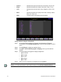
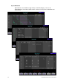
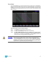
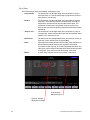
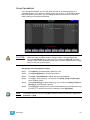
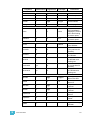
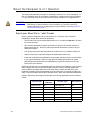
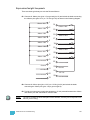
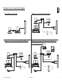
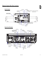
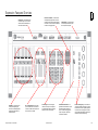
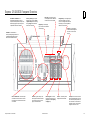
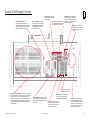
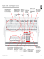
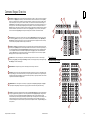
1
emphasis ® Lighting Control System Console User Manual v2.0.1 C o p y r i g h t © E le c tr o n i c T h e a t r e C o n t r o l s , I n c . All Rights reserved. P r o d u c t in f o r m a t i on a n d s p e c i f i c a t i o n s s u bj e c t t o c h a n g e . P a r t N u m b er : 4200M1211-2.0.1 R e v A Released: November 2004 ET C ®, E m p h a s i s ®, E x p r e s s io n ®, In s i g h t ™ , I m a g i n e ™ , F o c u s ™ , E x p r e s s ™ , U n i s o n ®, O b s e s s i o n ® II , E T C N e t 2 ™ , E D M X ™ , S e n s o r ®, a n d W Y S IL i n k ™ a r e e i th e r r eg i s t e r e d t r a d e m a r k s o r t r a d e m a r k s o f E l e c t r o n i c T h e a t r e C o n t r o l s , I n c . i n th e U n i t e d S ta t e s a n d o t h er c o u n t r i e s . T h e n a m e W Y S IW Y G ™ i s a tr a d e m a r k o f C A S T L i g h t i n g L i m i t e d . M i c r o s o f t ® a n d W in d o w s ® a r e r e g i s t e r e d t r a d e m a r k s o f M i c r o s o f t C o r p o r a t i o n i n t h e U n i t e d S t a t e s a n d o t h e r c o u n tr i e s . D e l l ® i s a r e g i s t e r e d t r a d e m a r k o f D e l l C o m p u t e r C o r p o r at i o n . A u t o d e s k ® a n d A u to C A D ® a r e r e g i s t e r e d t r a d e m a r k s o f A u t o d e s k , I n c . , i n t h e U n i t e d S t a te s a n d o th e r c o u n t r i e s . Table of Contents Introduction . . . . . . . . . . . . . . . . . . . . . .1 Using this Manual . . . . . . . . . . . . . . . . . . . . . . . . . . . . . . . . .2 Help from ETC Technical Services . . . . . . . . . . . . . . . . . . . .3 Americas . . . . . . . . . . . . . . . . . . . . . . . . . . . . . . . . . . . .3 Europe . . . . . . . . . . . . . . . . . . . . . . . . . . . . . . . . . . . . .3 Asia . . . . . . . . . . . . . . . . . . . . . . . . . . . . . . . . . . . . . . . .3 Chapter 1 System Overview . . . . . . . . . . . . . . . . .5 Emphasis Options . . . . . . . . . . . . . . . . . . . . . . . . . . . . . . . . .6 Server Types . . . . . . . . . . . . . . . . . . . . . . . . . . . . . . . . .6 Channel Counts . . . . . . . . . . . . . . . . . . . . . . . . . . . . . . .6 Facepanels . . . . . . . . . . . . . . . . . . . . . . . . . . . . . . . . . .6 System Components . . . . . . . . . . . . . . . . . . . . . . . . . . . . . . .7 Emphasis Server . . . . . . . . . . . . . . . . . . . . . . . . . . . . . .7 Emphasis Facepanel . . . . . . . . . . . . . . . . . . . . . . . . . . .7 Emphasis Visualization . . . . . . . . . . . . . . . . . . . . . . . . .8 Emphasis Console . . . . . . . . . . . . . . . . . . . . . . . . . . . . .8 Installation Guidelines . . . . . . . . . . . . . . . . . . . . . . . . . . . . . .9 Hooking Up the Hardware . . . . . . . . . . . . . . . . . . . . . . .9 Connecting a Printer . . . . . . . . . . . . . . . . . . . . . . . . . .10 Software Installation . . . . . . . . . . . . . . . . . . . . . . . . . .11 Registration . . . . . . . . . . . . . . . . . . . . . . . . . . . . . . . . .13 Upgrades . . . . . . . . . . . . . . . . . . . . . . . . . . . . . . . . . . .15 System Procedures . . . . . . . . . . . . . . . . . . . . . . . . . . . . . . .16 Power-up Procedure . . . . . . . . . . . . . . . . . . . . . . . . . .16 Multi-console Submaster Fader Support . . . . . . . . . . .16 Login as a Different User . . . . . . . . . . . . . . . . . . . . . . .17 Shut-down Procedure . . . . . . . . . . . . . . . . . . . . . . . . .17 Troubleshooting. . . . . . . . . . . . . . . . . . . . . . . . . . . . . . . . . .18 How do I find the software version? . . . . . . . . . . . . . . .19 Chapter 2 Emphasis Console User Interface . . .21 Emphasis Facepanel Options . . . . . . . . . . . . . . . . . . . . . . .22 Express Two-Scene . . . . . . . . . . . . . . . . . . . . . . . . . . .22 Express ECS . . . . . . . . . . . . . . . . . . . . . . . . . . . . . . . .22 Expression ECS . . . . . . . . . . . . . . . . . . . . . . . . . . . . . .22 Insight ECS . . . . . . . . . . . . . . . . . . . . . . . . . . . . . . . . .22 Setting the Facepanel Type on the Server . . . . . . . . .22 Accessories . . . . . . . . . . . . . . . . . . . . . . . . . . . . . . . . .24 Console Displays. . . . . . . . . . . . . . . . . . . . . . . . . . . . . . . . .28 Display Features . . . . . . . . . . . . . . . . . . . . . . . . . . . . .28 Stage, Blind and Fader . . . . . . . . . . . . . . . . . . . . . . . .29 Spreadsheet . . . . . . . . . . . . . . . . . . . . . . . . . . . . . . . .33 Tracksheet . . . . . . . . . . . . . . . . . . . . . . . . . . . . . . . . . .33 i Patch . . . . . . . . . . . . . . . . . . . . . . . . . . . . . . . . . . . . . .34 Park . . . . . . . . . . . . . . . . . . . . . . . . . . . . . . . . . . . . . . .34 Playback . . . . . . . . . . . . . . . . . . . . . . . . . . . . . . . . . . .35 Expression LED displays . . . . . . . . . . . . . . . . . . . . . . .35 Hard keys vs. Softkeys by Facepanel Type . . . . . . . . . . . .36 Softkeys . . . . . . . . . . . . . . . . . . . . . . . . . . . . . . . . . . . .39 Channel Concepts in the Emphasis Control System. . . . . .47 HTP vs. LTP . . . . . . . . . . . . . . . . . . . . . . . . . . . . . . . .47 Independent Channels . . . . . . . . . . . . . . . . . . . . . . . .47 Preset vs. Tracking . . . . . . . . . . . . . . . . . . . . . . . . . . .48 Chapter 3 System Settings . . . . . . . . . . . . . . . . .49 The Setup Menu . . . . . . . . . . . . . . . . . . . . . . . . . . . . . . . . .50 System Settings . . . . . . . . . . . . . . . . . . . . . . . . . . . . . .50 Options Settings . . . . . . . . . . . . . . . . . . . . . . . . . . . . .55 Clock Functions . . . . . . . . . . . . . . . . . . . . . . . . . . . . . .55 Clear Functions . . . . . . . . . . . . . . . . . . . . . . . . . . . . . .57 Print Functions . . . . . . . . . . . . . . . . . . . . . . . . . . . . . . .58 Macro List . . . . . . . . . . . . . . . . . . . . . . . . . . . . . . . . . .58 Time Code Events and Real Time Programs . . . . . . .58 Channel Attributes . . . . . . . . . . . . . . . . . . . . . . . . . . . .58 Profiles . . . . . . . . . . . . . . . . . . . . . . . . . . . . . . . . . . . . .60 Moving Light Functions . . . . . . . . . . . . . . . . . . . . . . . .61 Patch . . . . . . . . . . . . . . . . . . . . . . . . . . . . . . . . . . . . . . . . . .72 Interactivity with Emphasis Visualization . . . . . . . . . . .72 Range Patching . . . . . . . . . . . . . . . . . . . . . . . . . . . . . .73 EDMX . . . . . . . . . . . . . . . . . . . . . . . . . . . . . . . . . . . . .73 Disable/Enable the Facepanel DMX Ports . . . . . . . . .75 Disable/Enable EDMX on Powerup and Show Read .75 EDMX Output Range Settings . . . . . . . . . . . . . . . . . . .76 Modifying dimmer output . . . . . . . . . . . . . . . . . . . . . . .78 Label Dimmers . . . . . . . . . . . . . . . . . . . . . . . . . . . . . .81 Patching to a Strand Lighting CD80 Dimmer Rack . . .81 Using the About Command . . . . . . . . . . . . . . . . . . . . . . . . .82 About Dimmer . . . . . . . . . . . . . . . . . . . . . . . . . . . . . . .82 About Channel . . . . . . . . . . . . . . . . . . . . . . . . . . . . . . .82 About Show . . . . . . . . . . . . . . . . . . . . . . . . . . . . . . . . .83 Chapter 4 Live Editing . . . . . . . . . . . . . . . . . . . . .85 Displays. . . . . . . . . . . . . . . . . . . . . . . . . . . . . . . . . . . . . . . .86 Stage Display . . . . . . . . . . . . . . . . . . . . . . . . . . . . . . .86 Fader Display . . . . . . . . . . . . . . . . . . . . . . . . . . . . . . .87 Manual Control . . . . . . . . . . . . . . . . . . . . . . . . . . . . . . . . . .88 Select Channels, Dimmers and Fixtures . . . . . . . . . . .88 Set Levels . . . . . . . . . . . . . . . . . . . . . . . . . . . . . . . . . .91 Capture EDMX . . . . . . . . . . . . . . . . . . . . . . . . . . . . . .93 Captured channels and [Release] . . . . . . . . . . . . . . .94 Dimmer and Channel Check . . . . . . . . . . . . . . . . . . . .95 Solo . . . . . . . . . . . . . . . . . . . . . . . . . . . . . . . . . . . . . . .96 ii Emphasis Console v2.0.0 User Manual Moving Light Control . . . . . . . . . . . . . . . . . . . . . . . . . .97 Dynamic Effects . . . . . . . . . . . . . . . . . . . . . . . . . . . . .101 Sneak . . . . . . . . . . . . . . . . . . . . . . . . . . . . . . . . . . . .109 Channel Faders (Express Two-Scene/Insight only) .110 Groups . . . . . . . . . . . . . . . . . . . . . . . . . . . . . . . . . . . .110 Park . . . . . . . . . . . . . . . . . . . . . . . . . . . . . . . . . . . . . .111 Cues . . . . . . . . . . . . . . . . . . . . . . . . . . . . . . . . . . . . . . . . .114 Cue Types . . . . . . . . . . . . . . . . . . . . . . . . . . . . . . . . .114 Record Cues . . . . . . . . . . . . . . . . . . . . . . . . . . . . . . .115 Link Functions . . . . . . . . . . . . . . . . . . . . . . . . . . . . . .115 Tracking . . . . . . . . . . . . . . . . . . . . . . . . . . . . . . . . . . .116 Using Cues as Groups . . . . . . . . . . . . . . . . . . . . . . .118 Stage Effects . . . . . . . . . . . . . . . . . . . . . . . . . . . . . . .119 Move Before Bright (MBB) . . . . . . . . . . . . . . . . . . . . .119 Submasters . . . . . . . . . . . . . . . . . . . . . . . . . . . . . . . . . . . .123 Submaster Types . . . . . . . . . . . . . . . . . . . . . . . . . . .123 Record Submasters . . . . . . . . . . . . . . . . . . . . . . . . . .124 Using [Load Sub] . . . . . . . . . . . . . . . . . . . . . . . . . . .125 Using Submasters as Groups . . . . . . . . . . . . . . . . . .126 Time Functions . . . . . . . . . . . . . . . . . . . . . . . . . . . . . . . . .127 Cues . . . . . . . . . . . . . . . . . . . . . . . . . . . . . . . . . . . . .127 Submasters . . . . . . . . . . . . . . . . . . . . . . . . . . . . . . . .129 Special Functions . . . . . . . . . . . . . . . . . . . . . . . . . . . . . . .130 Except . . . . . . . . . . . . . . . . . . . . . . . . . . . . . . . . . . . .130 Solo . . . . . . . . . . . . . . . . . . . . . . . . . . . . . . . . . . . . . .130 Update . . . . . . . . . . . . . . . . . . . . . . . . . . . . . . . . . . . .131 Delete . . . . . . . . . . . . . . . . . . . . . . . . . . . . . . . . . . . .131 Label . . . . . . . . . . . . . . . . . . . . . . . . . . . . . . . . . . . . .132 Chapter 5 Blind Editing . . . . . . . . . . . . . . . . . . .133 Displays. . . . . . . . . . . . . . . . . . . . . . . . . . . . . . . . . . . . . . .134 Blind . . . . . . . . . . . . . . . . . . . . . . . . . . . . . . . . . . . . . .134 List Displays . . . . . . . . . . . . . . . . . . . . . . . . . . . . . . .135 Spreadsheets . . . . . . . . . . . . . . . . . . . . . . . . . . . . . .136 Tracksheet . . . . . . . . . . . . . . . . . . . . . . . . . . . . . . . . .137 Cues . . . . . . . . . . . . . . . . . . . . . . . . . . . . . . . . . . . . . . . . .138 Cue List . . . . . . . . . . . . . . . . . . . . . . . . . . . . . . . . . . .139 Spreadsheet . . . . . . . . . . . . . . . . . . . . . . . . . . . . . . .141 Tracksheet . . . . . . . . . . . . . . . . . . . . . . . . . . . . . . . . .144 Subroutines . . . . . . . . . . . . . . . . . . . . . . . . . . . . . . . . . . . .145 Subroutines in Cues . . . . . . . . . . . . . . . . . . . . . . . . .145 Subroutines on Submasters (Subs-on-Subs) . . . . . .148 Effects . . . . . . . . . . . . . . . . . . . . . . . . . . . . . . . . . . . . . . . .151 Blind Effects . . . . . . . . . . . . . . . . . . . . . . . . . . . . . . . .151 Submasters . . . . . . . . . . . . . . . . . . . . . . . . . . . . . . . . . . . .156 Submaster List . . . . . . . . . . . . . . . . . . . . . . . . . . . . . .156 Submaster Spreadsheet . . . . . . . . . . . . . . . . . . . . . .158 Supermasters . . . . . . . . . . . . . . . . . . . . . . . . . . . . . .160 Groups . . . . . . . . . . . . . . . . . . . . . . . . . . . . . . . . . . . . . . .161 iii Group List . . . . . . . . . . . . . . . . . . . . . . . . . . . . . . . . .162 Group Spreadsheet . . . . . . . . . . . . . . . . . . . . . . . . . .163 Focus Points . . . . . . . . . . . . . . . . . . . . . . . . . . . . . . . . . . .165 Focus Point List . . . . . . . . . . . . . . . . . . . . . . . . . . . . .166 Focus Point Spreadsheet . . . . . . . . . . . . . . . . . . . . .167 Chapter 6 Playback . . . . . . . . . . . . . . . . . . . . . .171 A/B and C/D Fader Pairs. . . . . . . . . . . . . . . . . . . . . . . . . .172 Fader Controls . . . . . . . . . . . . . . . . . . . . . . . . . . . . . .172 Playback Cue List . . . . . . . . . . . . . . . . . . . . . . . . . . .174 Fader Status display . . . . . . . . . . . . . . . . . . . . . . . . .175 Cue Playback . . . . . . . . . . . . . . . . . . . . . . . . . . . . . .176 Quickstep . . . . . . . . . . . . . . . . . . . . . . . . . . . . . . . . . .179 Multi-part Cues . . . . . . . . . . . . . . . . . . . . . . . . . . . . .179 Effect Cues . . . . . . . . . . . . . . . . . . . . . . . . . . . . . . . .179 Subroutine Cues . . . . . . . . . . . . . . . . . . . . . . . . . . . .179 Submasters . . . . . . . . . . . . . . . . . . . . . . . . . . . . . . . . . . . .181 Submaster Pages . . . . . . . . . . . . . . . . . . . . . . . . . . .181 Effects . . . . . . . . . . . . . . . . . . . . . . . . . . . . . . . . . . . .181 Subroutines on Submasters (Subs-on-Subs) . . . . . .181 Submaster Rate . . . . . . . . . . . . . . . . . . . . . . . . . . . . .182 Supermasters . . . . . . . . . . . . . . . . . . . . . . . . . . . . . .182 Chapter 7 Macros . . . . . . . . . . . . . . . . . . . . . . .183 Create Macros. . . . . . . . . . . . . . . . . . . . . . . . . . . . . . . . . .184 Learn Macro . . . . . . . . . . . . . . . . . . . . . . . . . . . . . . .184 Display Macros . . . . . . . . . . . . . . . . . . . . . . . . . . . . .184 Macro Editing . . . . . . . . . . . . . . . . . . . . . . . . . . . . . . .186 Special Macro Functions . . . . . . . . . . . . . . . . . . . . . .189 Playback Macros . . . . . . . . . . . . . . . . . . . . . . . . . . . . . . . .190 Remote Macros . . . . . . . . . . . . . . . . . . . . . . . . . . . . .190 Startup Macro . . . . . . . . . . . . . . . . . . . . . . . . . . . . . .190 Sample Macros . . . . . . . . . . . . . . . . . . . . . . . . . . . . . . . . .191 Chapter 8 Real Time Programs . . . . . . . . . . . . .193 Real Time Programs . . . . . . . . . . . . . . . . . . . . . . . . . . . . .194 Setting the time and location . . . . . . . . . . . . . . . . . . .194 Create and Edit Real Time Programs . . . . . . . . . . . .196 Enable Real Time Programs . . . . . . . . . . . . . . . . . . .199 Time and Location. . . . . . . . . . . . . . . . . . . . . . . . . . . . . . .200 Chapter 9 Control Interfaces . . . . . . . . . . . . . . .203 ETCNet2 . . . . . . . . . . . . . . . . . . . . . . . . . . . . . . . . . . . . . .204 EDMX Basics (ETCNet2 v4.0.0 and above) . . . . . . .204 iv Emphasis Console v2.0.0 User Manual DMX Output . . . . . . . . . . . . . . . . . . . . . . . . . . . . . . . .206 DMX Input . . . . . . . . . . . . . . . . . . . . . . . . . . . . . . . . .207 Remote Macros . . . . . . . . . . . . . . . . . . . . . . . . . . . . .207 Remote Trigger . . . . . . . . . . . . . . . . . . . . . . . . . . . . .208 Facepanel Configuration . . . . . . . . . . . . . . . . . . . . . . . . . .210 Show Control Overview. . . . . . . . . . . . . . . . . . . . . . . . . . .211 MIDI Basics . . . . . . . . . . . . . . . . . . . . . . . . . . . . . . . . . . . .212 ETC MIDI Message Formats . . . . . . . . . . . . . . . . . . .213 MIDI Message definitions . . . . . . . . . . . . . . . . . . . . .214 MIDI Show Control . . . . . . . . . . . . . . . . . . . . . . . . . . . . . .216 MIDI Show Control (MSC) Commands . . . . . . . . . . .216 MSC Frame Packet . . . . . . . . . . . . . . . . . . . . . . . . . .217 SMPTE . . . . . . . . . . . . . . . . . . . . . . . . . . . . . . . . . . . . . . .220 Time Code Program . . . . . . . . . . . . . . . . . . . . . . . . . . . . .221 Time Code Events Display . . . . . . . . . . . . . . . . . . . .221 Run a Time Code Program . . . . . . . . . . . . . . . . . . . .225 Emphasis Serial Button Protocol. . . . . . . . . . . . . . . . . . . .228 Commands . . . . . . . . . . . . . . . . . . . . . . . . . . . . . . . .228 Arguments . . . . . . . . . . . . . . . . . . . . . . . . . . . . . . . . .228 Command Examples . . . . . . . . . . . . . . . . . . . . . . . . .229 Input Stream Echoing . . . . . . . . . . . . . . . . . . . . . . . .229 Things to Keep in Mind... . . . . . . . . . . . . . . . . . . . . . .230 The Keyword Table . . . . . . . . . . . . . . . . . . . . . . . . . .230 Appendix A System Defaults . . . . . . . . . . . . . . . .235 Emphasis Visualization and Console Defaults . . . . . . . . .236 Facepanel Type . . . . . . . . . . . . . . . . . . . . . . . . . . . . .236 Diagnostics . . . . . . . . . . . . . . . . . . . . . . . . . . . . . . . .236 IO . . . . . . . . . . . . . . . . . . . . . . . . . . . . . . . . . . . . . . . .236 ASCII Options . . . . . . . . . . . . . . . . . . . . . . . . . . . . . .237 Emphasis Visualization Defaults . . . . . . . . . . . . . . . . . . . .238 Application Options . . . . . . . . . . . . . . . . . . . . . . . . . .238 Emphasis Console Defaults . . . . . . . . . . . . . . . . . . . . . . .239 Language . . . . . . . . . . . . . . . . . . . . . . . . . . . . . . . . . .239 System ID . . . . . . . . . . . . . . . . . . . . . . . . . . . . . . . . .239 Expression Facepanel Defaults . . . . . . . . . . . . . . . . . . . .240 Express Facepanel Defaults . . . . . . . . . . . . . . . . . . . . . . .242 Appendix B Maintenance and Troubleshooting . .243 Return the Facepanel to v3.1 Operation . . . . . . . . . . . . . .244 Export your Show File to “.shw” Format . . . . . . . . . .244 Create a v3.1 Console Software Disk . . . . . . . . . . . .245 Install v3.1 Console Software . . . . . . . . . . . . . . . . . .246 Open the Facepanel . . . . . . . . . . . . . . . . . . . . . . . . . . . . .247 v Spare parts kit . . . . . . . . . . . . . . . . . . . . . . . . . . . . . .247 Replacing fuses. . . . . . . . . . . . . . . . . . . . . . . . . . . . . . . . .248 Connecting desk lights (Express facepanels only) . . . . . .249 Expression and Insight DIP switches . . . . . . . . . . . . . . . .250 Internal DIP Switches . . . . . . . . . . . . . . . . . . . . . . . .250 VGA monitor connections . . . . . . . . . . . . . . . . . . . . . . . . .251 Connecting DMX cable to facepanel . . . . . . . . . . . . . . . . .252 Using an optional pointing device . . . . . . . . . . . . . . . . . . .253 Installation . . . . . . . . . . . . . . . . . . . . . . . . . . . . . . . . .253 Device check . . . . . . . . . . . . . . . . . . . . . . . . . . . . . . .253 Connecting an alphanumeric keyboard. . . . . . . . . . . . . . .254 Installing Remote Focus Unit . . . . . . . . . . . . . . . . . . . . . .255 Connecting MIDI . . . . . . . . . . . . . . . . . . . . . . . . . . . . . . . .256 MIDI Out/Thru jumper setting . . . . . . . . . . . . . . . . . .256 Connecting SMPTE (Expression and Insight only) . . . . . .258 SMPTE facepanel connector . . . . . . . . . . . . . . . . . . .258 Using Remote Macros. . . . . . . . . . . . . . . . . . . . . . . . . . . .259 Wiring Remote Macros . . . . . . . . . . . . . . . . . . . . . . .260 Expression/Insight facepanels . . . . . . . . . . . . . . . . . .261 Appendix C Lighting Playback Controllers . . . . . .263 Expression/Insight LPC Installation and Configuration . . .264 Installation Guidelines . . . . . . . . . . . . . . . . . . . . . . . .264 Configuration Guidelines . . . . . . . . . . . . . . . . . . . . . .264 Expression/Insight LPC User Interface . . . . . . . . . . . . . . .265 The Cue Playback Display . . . . . . . . . . . . . . . . . . . .265 The Macro Playback Display . . . . . . . . . . . . . . . . . . .265 The Edit Display . . . . . . . . . . . . . . . . . . . . . . . . . . . .265 Express LPC Installation and Configuration . . . . . . . . . . .266 Rack-mount Installation . . . . . . . . . . . . . . . . . . . . . . .266 Surface-mount Installation . . . . . . . . . . . . . . . . . . . . .267 Install Cables . . . . . . . . . . . . . . . . . . . . . . . . . . . . . . .268 Configuration Guidelines . . . . . . . . . . . . . . . . . . . . . .268 Express LPC User Interface . . . . . . . . . . . . . . . . . . . . . . .269 Appendix D Specifications . . . . . . . . . . . . . . . . . .271 Emphasis Control System Specifications . . . . . . . . . . . . .272 Express Facepanel Specifications . . . . . . . . . . . . . . . . . .278 Expression Facepanel Specifications . . . . . . . . . . . . . . . .282 Insight Facepanel Specifications. . . . . . . . . . . . . . . . . . . .287 vi Emphasis Console v2.0.0 User Manual Appendix E Foldout Diagrams . . . . . . . . . . . . . . .293 Emphasis Control System Riser Diagrams . . . . . . . . . . . 295 Emphasis Facepanel Rear Panel Connections. . . . . . . . 296 Insight Facepanel Overview . . . . . . . . . . . . . . . . . . . . . . 297 Expression Facepanel Overview. . . . . . . . . . . . . . . . . . . 298 Express 125/250/ECS Facepanel Overview . . . . . . . . . . 299 Express 24/48 Facepanel Overview . . . . . . . . . . . . . . . . 300 Express 48/96 & 72/144 Facepanel Overview . . . . . . . . 301 Emphasis LPC Facepanel Overview. . . . . . . . . . . . . . . . 302 Command Keypad Overview. . . . . . . . . . . . . . . . . . . . . . 303 Express Facepanel Two-Scene Operation . . . . . . . . . . . 304 Overview . . . . . . . . . . . . . . . . . . . . . . . . . . . . . . . . . .304 Setup Two-scene Operation . . . . . . . . . . . . . . . . . . .304 Playback Looks using the AB Fader Pair . . . . . . . . .304 Playback Looks with Timing . . . . . . . . . . . . . . . . . . .304 vii This page intentionally blank. viii Emphasis Console v2.0.0 User Manual Introduction This manual covers the basic installation and operation of the Emphasis Control System. Specifically, this volume contains the operational instructions for Emphasis Console, the facepanel interface to your Emphasis Control System. For information on using Emphasis Visualization, please see the Emphasis Visualization User Manual. The introduction contains the following sections: • Using this Manual . . . . . . . . . . . . . . . . . . . . . . . . . . . . . . . . . . . 2 • Help from ETC Technical Services . . . . . . . . . . . . . . . . . . . . . 3 If you are reading these manuals cover-to-cover, please begin with the Emphasis Visualization User Manual. The Emphasis Visualization User Manual contains a Quick Start chapter that contains a tutorial for new users, and some basic information for users familiar with WYSIWYG and/or Expressionstyle consoles. Introduction 1 Using thi s Manual This manual is intended for use in conjunction with the Emphasis Visualization User Manual. This manual assumes that you have a basic familiarity with the Microsoft Windows® operating system, opening and closing files, closing and resizing windows, using Windows Explorer, and performing basic disk operations. In order to be specific about where features and commands are found, the following naming and text conventions will be used: Note: • Emphasis™ Server (hardware): the computer used to run the Emphasis applications. This is also referred to simply as the “Server”. • Emphasis Facepanel (hardware): the control console hardware. This is also referred to simply as the “Facepanel”. • Emphasis Visualization (software): the application that resides solely on the Server and provides WYSIWYG™-based functionality. • Emphasis Console (software): the application that drives the Facepanel. The Console displays resemble the traditional Facepanel displays, and can be viewed on either the Server or Facepanel monitors. This application usually remains hidden, as the displays can be accessed through the Facepanel and Visualization. • Menus and commands found on the Server are indicated in bold text. For example: In the File menu, click Open. • Server keyboard buttons are indicated in all CAPS. For example, TAB or CTRL. • Facepanel buttons and softkeys are indicated in bold [brackets]. For example, [Stage] or [Enter]. Optional keys are indicated in <angle brackets>, for example, <Fixture> or <Channel>. A note about <S7 - More Softkeys>: this command is always indicated as optional, and is only indicated once in an instruction regardless of how many pages of softkeys exist. This is because there is no way to predict what softkey page you are on at any given time. Press <S7 - More Softkeys> until you find the required command. • References to other parts of the manual are indicated in italics. When viewing this manual electronically, click on the reference to jump to that section of the manual. Notes are helpful hints and information that is supplemental to the main text. CAUTION: WARNING: A Caution statement indicates situations where there may be undefined or unwanted consequences of an action, potential for data loss or an equipment problem. A Warning statement indicates situations where damage may occur, people may be harmed, or there are serious or dangerous consequences of an action. Please email comments about this manual to: [email protected] 2 Emphasis Console v2.0.0 User Manual Help from ETC Technical Services If you are having difficulties, your most convenient resources are the references given in this manual and the Help system. To search more widely, try the ETC website at www.etcconnect.com. If none of these resources is sufficient, contact ETC Technical Services directly at one of the offices identified below. Emergency service is available from all ETC offices outside of normal business hours. When calling for help, please have the following information handy: • Console model and serial number (located on back panel) • Emphasis Server serial number (located inside the door on the front of the Server case) • Software version (see How do I find the software version?, page 19) • Dimmer manufacturer and installation type • Moving light information (manufacturer, mode, data cable type) • Other components in your system (Unison®, other consoles, etc.) Americas ETC International Technical Services Department 3031 Pleasant View Road Middleton, WI 53562 +1-800-775-4382 +1-608 831-4116 [email protected] Europe ETC Europe Ltd. Technical Services Department 5 Victoria Industrial Estate Victoria Road, London W3 6UU England +44 (0)20 8896 1000 [email protected] Asia ETC Asia, Ltd. Technical Services Department Room 605-606 Tower III, Enterprise Square 9 Sheung Yuet Road Kowloon Bay, Kowloon, Hong Kong +852 2799 1220 [email protected] Introduction 3 This page intentionally blank. 4 Emphasis Console v2.0.0 User Manual Chapter 1 System Overview Emphasis integrates the functionality of WYSIWYG with the Expression-style control consoles to give you a powerful, but user-friendly, control system offering both a graphical, point-and-click environment and a tactile button-and-wheel interface. Emphasis ensures consistency and accuracy with total integration of data across all modes. Data input in any mode is applied through the paperwork, on the light plot, in the console patch, on reports, and on screen, in every view. This chapter contains the following sections: 1 • Emphasis Options . . . . . . . . . . . . . . . . . . . . . . . . . . . . . . . . . . 6 • System Components . . . . . . . . . . . . . . . . . . . . . . . . . . . . . . . . 7 • Installation Guidelines . . . . . . . . . . . . . . . . . . . . . . . . . . . . . . . 9 • System Procedures . . . . . . . . . . . . . . . . . . . . . . . . . . . . . . . . 16 • Troubleshooting . . . . . . . . . . . . . . . . . . . . . . . . . . . . . . . . . . . 18 System Overview 5 Emphasi s Opti ons Emphasis systems are created by choosing the server type, maximum channel count and Facepanel type. Emphasis is offered as an upgrade to an existing Express or Expressionstyle console (see below for compatible Facepanel types), or as a complete package. Server Types • 3D - Includes full console feature set and full visualization functionality: paperwork and presentation tools, data tasks, 3D CAD drafting, complete visualization and rendering. The 3D Server will support up to two monitors. • 2D - Includes full console feature set and limited visualization functionality: paperwork and presentation tools, data tasks, and 2D CAD drafting. The 2D Server will support one monitor. Channel Counts • 500 channels • 1000 channels • 2500 channels • 5000 channels • 10,000 channels (2D only) Channel counts refer to the maximum number of control channels you can have in a show. All channel options have 32,767 EDMX™ addresses available. Facepanels 6 • Expression with Emphasis (Expression ECS), Expression 3, Expression 2x, Expression LPC, Imagine™ 3 • Insight™ with Emphasis (Insight ECS), Insight 3, Insight 2x, Insight LPC, Focus™ • Express (all varieties), Express LPC Emphasis Console v2.0.0 User Manual System Components Emphasis Server The Emphasis server is a Dell® computer optimized by ETC for the best performance of the Emphasis Visualization and Emphasis Console applications. The Server is provided preconfigured and should not require any software installations for its initial use. This section contains information on specific differences between your Server and a regular PC. The Server contains all of the software required for Emphasis to run, a hard drive for show data storage, a CD-RW drive for show data storage, and a 3.5” floppy drive for Facepanel Software Disk creation. There is a special hardware key called a “dongle” inside your Server, coded for the software features you have purchased. If this is removed, Emphasis will not run. This dongle is not usable on other computers and cannot be used with WYSIWYG stand-alone applications. Note: There are two USB ports located behind the door on the front of your Server. The Emphasis dongle is connected internally to the rear port of this pair, so it may not be used for other USB devices. The front port is available for your use. A keyboard and mouse are included with your Server. The keyboard may have a number of buttons designed for use with common internet tasks. These buttons have been disabled, as the Server should not be connected to the internet at any time. When you power up your Server, it will automatically launch the Emphasis applications. The first time you do this, the Registration dialog box will appear (see Registration, page 13). Emphasis Servers can be configured for 2D or 3D operation. The following table illustrates the differences between the standard 2D and 3D Servers: Feature Monitors CAD Views Emphasis Views Rendering 2D Server 1 Wireframe only Wireframe only No 3D Server Up to 2 Wireframe, Isometric and Shaded Wireframe, Isometric and Shaded Yes Emphasis Facepanel The Emphasis Facepanel can be any of the following consoles: • Expression with Emphasis, Expression 3, Expression 2x, Imagine™ 3 • Insight™ with Emphasis, Insight 3, Insight 2x, Focus™ • Express (all varieties) When used in an Emphasis system, the Facepanel becomes an input device on the network, rather than a stand-alone device. You are limited to some of the constraints of the individual Facepanel types, such as submaster quantities, channel-fader availability and monitor counts; however, you gain cue-, channel- and dimmer-counts, as well as ETCNet2 capability when connected to an Emphasis Server. When a Facepanel has been upgraded to Emphasis operation, it will no longer operate as a stand-alone console. The Facepanel essentially becomes a keyboard with some DMX Node functionality. As such, the Facepanel cannot operate without the Emphasis Server online. In case of an emergency, you can export your Emphasis show file as a v3.1 show, reload the v3.1 software to your Facepanel and run it as a stand-alone console. The 1 System Overview 7 procedure for exporting your show to v3.1 format is described in the Emphasis Visualization User Manual. The procedure for returning your Facepanel to v3.1 operation is described in Return the Facepanel to v3.1 Operation, page 242. Emphasis Visualization Emphasis Visualization is the software application that provides the graphic interface to the Emphasis Control System. It is based on the powerful WYSIWYG suite of software applications. This is where you patch your show, create your plot and prepare your paperwork. You can also select and control fixtures, pre-cue your show and preview recorded cues using the visualization features. While Emphasis Visualization is based on WYSIWYG, there are some significant changes that allow for interaction with the Emphasis Console. See the Emphasis Visualization User Manual for more information on these new features. Emphasis Console Emphasis Console is the software application that drives the Facepanel. This application usually remains hidden. You can access the settings and controls either from the Facepanel or from the virtual Facepanel in Emphasis Visualization. 8 Emphasis Console v2.0.0 User Manual Installation Guidel ines Hooking Up the Hardware Emphasis systems can range from a simple Server and Facepanel combination to fully integrated network systems. Regardless of the size of your system, there are some basic connections that are common to all systems. Note: See Expression and Insight DIP switches, page 248 for the correct network settings. Incorrect settings will not allow your Facepanel and Server to communicate. Emphasis uses UTP (Unshielded Twisted Pair) cable and a hub or switch for communication between the Facepanel and Server. A hub or switch is required for network connections between Facepanels, Servers and other network devices such as ETCNet2™ Nodes and Unison Architectural Controls. In all cases, networking equipment and cables must meet or exceed the Cat 5 standard. To connect your system devices: Note: Step 1: Place your Facepanel and Server on a stable, flat surface. The Server may be placed flat (horizontally) on the table or on its edge (vertically). The Server’s CD tray is designed to work in either orientation. Step 2: Connect the Facepanel Twisted Pair jack to the Server using UTP cable through a hub or switch. Step 3: Connect DMX cables to the Facepanel DMX outputs. You may also connect DMX cables to Nodes, if available. Step 4: Note: You may also connect your RFU cable to a Node, if available. Step 5: If you have ETCLink in your system, the cable must be connected to an ETCLink-enabled DMX Node. The ETCLink connector on your Facepanel is not supported in Emphasis. Step 6: Connect any MIDI or SMPTE cables to the appropriate connectors on the Facepanel. Step 7: Connect the Dell keyboard and mouse that came with the Server to the appropriate connectors on the Server. These connections are colour coded. You may also have a second keyboard connected to the Facepanel, if desired, for labeling items on the console, such as cues, groups and submasters. The second keyboard is not required, but may be added for convenience. Step 8: Connect your monitors. There will be at least one monitor on the Server and one on the Facepanel. • Servers configured for 2D operation will only support one monitor. Step 9: 1 Connect RFU cable to the Facepanel RFU connector. System Overview • Servers configured for 3D operation are supplied with a dual-video card. Monitors are connected to this card using a Y-cable, provided with your Server. • Expression and Insight consoles support two monitors. Express consoles support one monitor only. Connect power cables to Server, Facepanel, and hubs or switches. 9 CAUTION: When you plug in the server it may boot - it may not wait for you to press the power button. If the keyboard and/or mouse are not plugged in when you power up, they will not be recognized by the Server. You will have to force the Server to power down, plug them in, and restart. Connecting a Printer Connecting a printer to your Emphasis Server follows the same setup rules as any Windows computer. If your printer requires a software installation, you will need to logon as the System Manager. If you have problems connecting a printer to your Emphasis Control System, please contact ETC Technical Services (see Help from ETC Technical Services, page 3). Install a printer from the System Manager login: Step 1: Login as the System Manager (see Login as a Different User, page 17). Step 2: Right-click on Start menu on task bar and click Explore. Alternatively, you can press á+E to launch Windows Explorer at any time. Step 3: Click to expand My Computer in the file tree. Step 4: Click Control Panel. Step 5: Double-click Printers and Faxes. Step 6: Double-click Add Printers. Step 7: Uncheck Automatically detect and install my Plug and Play printer. If this is left checked, you will be asked for a password that you do not have. Step 8: Continue through the wizard to setup your printer. CAUTION: 10 Modification to hardware or software components or settings may affect the stability of the Emphasis Control System. Consult ETC Technical Services before making any changes. Non-authorized changes resulting in instability may require reloading the operating system, which will restore defaults, remove any changes, and may result in a loss of existing show files. Emphasis Console v2.0.0 User Manual Software Installation Your Emphasis Server will arrive with all software fully installed. If you have purchased a complete Emphasis Control System, including an Emphasis Server and a Facepanel, the Facepanel Software should also be loaded and ready to use. If you have purchased Emphasis as an upgrade to an existing Express or Expression-style console, you will need to upgrade the software in your console. I n s ta l l i n g F a c e p a n e l S o f t w a r e If you have purchased Emphasis as an upgrade to an existing console, or if you install a new version of software on your Emphasis Server, you will also need to update the software version in your Facepanel. If Facepanel Software disks are not provided or are lost, you can create your own Facepanel Software disk. The Facepanel Software Disk must be a 3.5” HD floppy disk. You may also create v3.1 software disks for Express and Expression-style consoles. This provides a way to return a Facepanel to v3.1 operation as a backup. It is recommended to keep separate disks for v3.1 and Emphasis Facepanel software on hand. To create and install a Facepanel Software Disk: Step 1: Exit Emphasis. Step 2: Insert a 3.5” HD floppy disk into the floppy drive on the Emphasis Server. Step 3: Login as System Manager (See Login as a Different User, page 17). CAUTION: Modification to hardware or software components or settings may affect the stability of the Emphasis Control System. Consult ETC Technical Services before making any changes. Non-authorized changes resulting in instability may require loading the operating system, which will restore defaults, remove any changes, and may result in a loss of existing show files. Step 4: Click OK to clear the warning screen. Step 5: Open the Facepanel Software folder located on the desktop. Step 6: Double-click the appropriate Facepanel Software file. • EmphExpression.exe - for Expression and Insight facepanels used with an Emphasis Control System. • EmphExpress.exe - for Express facepanels used with the Emphasis Control System. Step 7: Click Unzip to extract the software onto the floppy disk. Step 8: Click OK when completed. Step 9: Close the WinZip window and the Facepanel Software window. Step 10: In the Windows Start menu, click Log Off. Click the Log Off button in the dialog that opens. This will return you to the Emphasis Login screen. Step 11: Click Emphasis to login as the Emphasis User. Step 12: Eject the floppy disk from the Emphasis Server. Insert the floppy disk into the disk drive on the Facepanel. Step 13: Power up the Facepanel. The software will load automatically. Step 14: When completed, eject the floppy disk from the disk drive and restart the Facepanel. Step 15: Press [u] or [v] to select the Emphasis Server (processor) to connect to. You will need to arrow-down to select the processor, even if only one processor is listed. 1 System Overview 11 Step 16: Press [Enter]. The Facepanel will boot and the Stage displays will open on the attached monitors. I n s ta l l i n g S o f t w a r e o n t h e E m p h a s i s S e r v e r If you are reinstalling a new version of software, you will be provided specific instructions for installation with the release notes for that version. When installing Emphasis software, you are given the opportunity to install only Emphasis program files (located on the C drive) or to install a full disk image for both the C and D drives. CAUTION: Installing a full disk image for the C and D drives will delete show files stored on the Emphasis Server. It is highly recommended to backup all show files before loading new software. To backup existing show files see the Emphasis Visualization User Manual. To install new software: Step 1: Power up the Emphasis Server. Step 2: When the Dell screen appears, press F12. Step 3: Insert Emphasis Software CD #1 into the CD drive on the Emphasis Server. Step 4: Press the number corresponding to Boot from IDE CD ROM and press ENTER. Step 5: A warning screen appears allowing you to choose to continue or abort: • If you want to continue with the installation process, press any key. • Step 6: The installation type screen appears. Choose the type of installation you want to perform: • Install Emphasis Program files only (press “E”). This option restores the disk image of the C drive only, show files are retained. • CAUTION: 12 If you want to abort the installation process, Press CTRL+C. When prompted to “Terminate batch job (Y/N)?”, press “Y”. The DOS prompt will appear. You may restart the Emphasis Server (press CTRL+ALT+DELETE) at this point for normal operation. Install full disk image (press “A”). This option restores the disk image of the C and D drives, show files are deleted. Installing a full disk image for the C and D drives will delete show files stored on the Emphasis Server. Step 7: After you press “E” or “A”, the disk image begins to load from the Emphasis Software Disk #1. You will be prompted to load subsequent disks by the disk utility. Eject the first disk and load the next disk and press ENTER. Step 8: When completed, you will be prompted to remove the final CD from the drive and restart the Emphasis Server. You can restart the Emphasis Server by pressing the power button twice, or by pressing CTRL+ALT+DELETE. Step 9: After a new version of software has been installed on your Emphasis Server, you will need to install Facepanel Software. See Installing Facepanel Software, page 11, for that procedure. Emphasis Console v2.0.0 User Manual Registration When you first start your Emphasis Control System, you will be prompted to register the system. Registration will enable ETC to track your system for support purposes, and will enroll your system in the software subscription included with your Emphasis Control System, providing you with software upgrades for the duration of the subscription. You have 15 days to use the system prior to registering; however, it is recommended that you register your system as soon as possible. After 15 days have passed, you will not be able to use Emphasis Visualization until you enter the registration code. You may register your Emphasis Control System by phone, fax or email. To register by phone: 1 Step 1: Power up the Emphasis Server. If the system is unregistered, the Registration dialog should open. You can also open the Registration dialog using the Help menu Registration command. Step 2: In the Register dialog, click the Phone button. Step 3: Call ETC at one of the given phone numbers and speak to a Customer Service Representative. You will need to provide them with the Registration Request Code and your contact details. They will provide you with a Registration Validation Code to enter in the dialog. Step 4: Enter the Registration Validation Code in the dialog. Make sure to use all uppercase letters when you enter the code. Step 5: Click Register. System Overview 13 To register by fax: Note: 14 Step 1: Fill out the registration form included with your Emphasis Server. Fax it to the appropriate fax number based on your location. You will be sent a Registration Validation Code within a full business day. Step 2: If you cannot find the form, you can print a new copy from the Emphasis Server. Ensure you have a printer connected to your Emphasis Server. See Connecting a Printer, page 10, for more information. Step 3: Power up the Emphasis Server. If the system is unregistered, the Registration dialog should open. You can also open the Registration dialog using the Help menu Registration command. Step 4: In the Register dialog, click the Fax button. Step 5: Print the form, fill in all the information and fax it to the appropriate number indicated on the form. You will be sent a Registration Validation Code within a full business day. Alternatively, you can email your registration (all the information required on the fax form) to [email protected]. Step 6: When you receive your Registration Validation Code, take it to your Emphasis Control System. Power up the Emphasis Server. If the system is unregistered, the Registration dialog should open. You can also open the Registration dialog using the Help menu Registration command. Step 7: In the Register dialog, click the “I have my validation code” button. Enter the Registration Validation Code in the dialog. Make sure to use all uppercase letters when you enter the code. Step 8: Click OK. Emphasis Console v2.0.0 User Manual Upgrades To upgrade your Emphasis Control System, contact the ETC dealer who provided your Emphasis Control System to purchase the upgrade. When purchased, you will receive an Upgrade Code that will unlock the new features you have purchased. You can upgrade from a lower channel count to a higher channel count, and/or from 2D to 3D operation. You can also purchase an activation code for the Wireless Remote Focus Unit (WRFU) and/or WYSILink™. If you want to upgrade from a single monitor system to a dual monitor system to expand your desktop area, you may need to send the Emphasis Server back to ETC for that hardware upgrade. This hardware upgrade does not affect any functional abilities of the Emphasis Control System, only the available monitor space. Emphasis 3D will operate the same on single and dual monitor systems. To upgrade your Emphasis Control System: 1 Step 1: Contact your ETC dealer to purchase your Upgrade Code. When you have your Upgrade Code, continue to Step 2. Step 2: Power up your Emphasis Server. Step 3: In the Help menu, click Upgrade. Step 4: Enter your Upgrade Code in the dialog box. Make sure to use all uppercase letters when you enter the code. Step 5: Verify that the code you have entered is correct. Step 6: Click the Upgrade button. Step 7: Close and restart Emphasis. Your upgrade will take effect on the restart. System Overview 15 System Procedures Power-up Procedure For best performance, power-up your system in the following order: Note: Note: Step 1: Turn on the hub(s) and/or switch(es). Step 2: Turn on the Server and monitor(s). Wait for the Emphasis application to start up completely before proceeding to the next step. In a network with multiple Emphasis Control Systems online, allow one Emphasis Server to fully startup before starting the other Emphasis Servers. This will ensure that your network configures correctly. Step 3: Turn on the Facepanel(s) and monitor(s). Step 4: Turn on any ETCNet2 Nodes. Step 5: Turn on accessories such as Remote Focus Units. Emphasis defaults to starting in Show Mode. In Show Mode, CAD, PRES and LINK modes are hidden. To enter advanced mode for the current show file, in the File menu, click Show Mode. You will be asked to save changes to the current show because the show will be closed and reopened in advanced mode automatically. You can also load a different show file in either Show Mode or advanced mode using the File menu Load Show command. Select or deselect the Show Mode box at the bottom of the file browser to load the show in the appropriate mode. When you power-up your Emphasis Control System, the system will default to opening the last valid show file. If the show file is no longer available in the Shows directory, Emphasis will open a new show called “Untitled”. You may setup the system to open a new show on startup if you wish. See Create a Default Show in the Emphasis Visualization User Manual for more information. Multi-console Submaster Fader Support Multi-Console Submaster Fader Support enables control of submasters from all connected Emphasis Facepanels. Virtual submasters will always track the true fader level and indicate the active output level of the submaster. Physical submasters can gain control by matching the current true level. Once the level has been matched, the true level tracks the physical fader. Physical submasters from another connected Facepanel can take control in the same way. Submaster LEDs indicate physical submasters that are not in control. If the submaster fader needs to move up to match the true level, the LED blinks on twice followed by a longer “off” gap. If the submaster needs to be brought down to match, the LED blinks off twice followed by a longer “on” gap. 16 Emphasis Console v2.0.0 User Manual Login as a Different User There are a number of different user accounts contained in the Emphasis system. When the system is turned on, it will open using the Emphasis User settings. To gain access to the other user accounts, exit Emphasis. Note: When you load new system software onto your Emphasis Server, you will see an advisory indicating that the library indices are being rebuilt the first time each user type logs in. This is normal behavior. • Emphasis User: This user account is not password protected, and is the default user when Emphasis launches on startup. When this user type is selected, access is limited mainly to Emphasis. Other applications and computer components are hidden. When this user account is selected, critical program files may not be deleted (this does not include show files) and no other software may be installed. • NCE User: This user account is primarily for adjusting settings in the Network Configuration Editor (NCE) application. There is no password protection for this user type. When this user account is selected, critical program files may not be deleted (this does not include show files) and no other software may be installed. • System Manager: The System Manager has access to set the password for this user account, as well as partial Administrative rights, installation of software, system maintenance, Facepanel code, and all Emphasis and NCE user privileges. • Technical Services: This user type is reserved for ETC Technical Services and is password protected. To change the System Manager password: Step 1: Exit Emphasis and login as the System Manager. Step 2: In the Windows Start menu, click All Programs, then click User Accounts. The User Accounts dialog will open. Step 3: Under “Pick a task...”, click “Create a password”. Step 4: Follow the directions in the dialog to create a password and a password hint for the System Manager account. When complete, click the Create Password button at the bottom of the dialog box. Shut-down Procedure To shut-down your Emphasis Control System: 1 Step 1: In the Emphasis Visualization File menu, click Save to save your show file. Step 2: In the File menu, click Exit. You may also click the Exit button at the top-right corner of the Emphasis Visualization window. Step 3: In the lower-left corner of the Login screen, click Shutdown Emphasis Server. The “Turn off computer” dialog opens. Step 4: Click Turn Off to shut the Server down completely. Alternatively, click Stand By to place the Server in stand by mode or click Restart to cause the Server to reboot. Click Cancel to return to the Login screen without shutting down the Server. Step 5: Turn off any peripheral equipment, such as Nodes and Remote Focus Units. Step 6: Turn off the Facepanel at the power switch located on the rear panel. System Overview 17 Troubleshooting The Emphasis Facepanel type defaults to the Expression 3 console. This affects the video output of your Facepanel and the virtual facepanel in Emphasis Visualization. If you have an Insight or Express console as your Emphasis Facepanel, or if you swap Facepanels from an Expression-style to an Insight or Express, you will need to change the default settings to reflect this in the Emphasis Visualization, Emphasis mode Setup menu. See Setting the Facepanel Type on the Server, page 22 for more information. Note: If you have a show open and only the Emphasis mode is available, you are operating in Show Mode. See the Emphasis Visualization User Manual: Load Show for information on leaving Show Mode. The Emphasis Server is provided fully configured from the factory. It should not be treated as a regular desktop computer. The following modifications to the factory setup are known to cause problems of varying severity: • Screen savers. Do not enable screen savers on the Emphasis server. They can cause unexpected behavior in your system. • Power settings are set to never turn off the monitor(s) or the hard disk. The system is also set to never go into standby mode on its own. The “Sleep” button on the keyboard is also disabled. Do not put your Emphasis Server into standby or sleep mode while running Emphasis software. • Microsoft Windows XP appearance. Windows XP appearance settings are graphics heavy and will impact the performance speed of your system. The appearance settings are set to minimize the impact of the operating system on performance. • View contents while dragging windows. This setting is also graphics-heavy and will impair the performance speed of your system. • Wallpaper on the desktop. Wallpapers are graphics heavy and will impact the performance speed of your system. The wallpaper is set to “None” as a default. • Additional software applications (games, internet browsers, word processors, etc.). It is not advisable to load additional applications onto your Emphasis Server. Conflicts may occur between applications that could severely impact your system’s performance. The Emphasis Server should not be connected to the Internet. • On a 3D Server with dual monitors, you may experience problems with shaded views, especially on the second monitor. If your shaded views appear to refresh incorrectly (especially after shaded view windows have been overlapped), you may want to change the OpenGL options to “Safe Rendering”. • Do not enable hyperthreading on GX270 or GX280 servers. Hyperthreading causes the server to operate a single processor as if it were a dual processor system. This has been known to cause Emphasis to crash. To change the OpenGL settings: Step 1: In the Emphasis Visualization Options menu, click Application Options. Step 2: Click the OpenGL tab. Step 3: Click the button for the following settings: • Fast Rendering: This is the ideal setting. • 18 Fast Rendering for Primary Display Only: (Default) This sets the primary monitor to Fast Rendering and the second monitor to Safe Rendering and will solve the incorrect refresh problem on the second monitor. Emphasis Console v2.0.0 User Manual • Safe Rendering: This sets both monitors to “Safe Rendering”. If you have problems using your Emphasis Control System, please refer to your manuals for additional information. If you do not find the answer in a manual, please call your local dealer or ETC Technical Services (see Help from ETC Technical Services, page 3. Please have the following information available before you call: • Console model and serial number (located on back panel) • Emphasis Server serial number (located inside the door on the front of the Server case) • Software version (see below) • Dimmer manufacturer and installation type • Moving light information (manufacturer, mode, data cable type) • Other components in your system (Unison, other consoles, etc.) How do I find the software version? Emphasis is actually a suite of software, all with different version numbers. In general, all you need to provide to Technical Services is the suite version number. To find the Emphasis Control System suite version number: Step 1: In the Emphasis Visualization Help menu, click About Emphasis. The About... dialog box will open. Step 2: Find the Emphasis Visualization Version number at the top of the dialog box. The suite version number is indicated in parentheses at the end of the full version number. To find the suite version number outside Emphasis Visualization: Note: 1 Step 1: Minimize Emphasis Visualization and right-click on Start menu on task bar and click Explore. Alternatively, you can press á+E to launch Windows Explorer at any time. Step 2: Right-click My Computer and click Properties. Step 3: Click the General tab. You will find the Windows version information as well as the Emphasis system version. The Support Info button also displays the version number, as well as the phone numbers for ETC Americas, ETC Europe and ETC Asia. You can also use the shortcut á+PAUSE/BREAK to view the System Properties. System Overview 19 If you are asked to provide specific component version numbers, it is recommended that you use the first method to find all the version numbers at the same time. If that is not possible, use one of the other methods to find the specific information you are looking for. To find the complete list of version numbers on the Server: Note: Step 1: Minimize Emphasis Visualization and right-click on Start menu on task bar and click Explore. Alternatively, you can press á+E to launch Windows Explorer at any time. Step 2: Navigate to this location: C:\Program Files\ETC Step 3: Double-click the Emphasis Component Report. This report contains version information for all the installed Emphasis components. Note that this will not update version information if you have upgraded individual components rather than the whole disk image. To find the Emphasis Visualization version number: In the Help menu, click About Emphasis. To find the Emphasis Console version number: Step 1: Minimize Emphasis Visualization and maximize Emphasis Console. Step 2: In the Help menu, click About. To find the Facepanel version number: Restart the Facepanel and watch CRT1. The Facepanel version number appears on the bottom of the screen just after the boot screen and before the ETC logo. 20 Emphasis Console v2.0.0 User Manual Chapter 2 Emphasis Console User Interface This chapter covers the variations in the available Emphasis Facepanels: Express, Expression and Insight. It also covers the available accessories that can be used within your Emphasis Control System, including the Remote Focus Unit (RFU) and Wireless Remote Focus Unit (WRFU). This chapter also describes the different softkey setups of the various Facepanels, and the basic channel concepts behind the Emphasis Control System. This chapter contains the following sections: 2 • Emphasis Facepanel Options . . . . . . . . . . . . . . . . . . . . . . . . 22 • Console Displays . . . . . . . . . . . . . . . . . . . . . . . . . . . . . . . . . . 28 • Hard keys vs. Softkeys by Facepanel Type . . . . . . . . . . . . . 36 • Channel Concepts in the Emphasis Control System . . . . . 47 Emphasis Console User Interface 21 Emphasi s Facepanel Options The Emphasis Control System is compatible with a number of Express and Expressionstyle facepanels. The Emphasis Facepanel is used as an input device for channel selection, recording and playback, as well as an output device for DMX data. Express Two-Scene This facepanel type includes the Express 24/48, the Express 48/96 and the Express 72/ 144. For more information on the features of this facepanel type, see foldouts F:Express 24/48 Facepanel Overview, page 298, and G:Express 48/96 & 72/144 Facepanel Overview, page 299. The Emphasis Visualization virtual console does not include twoscene operation, only submasters, for this facepanel type. Express ECS This facepanel type includes the Express 125, the Express 250 and the Express ECS. For more information on the features of this facepanel type, see foldout E:Express 125/250/ ECS Facepanel Overview, page 297. The Emphasis Visualization virtual console emulates all facepanel controls for this facepanel type. Expression ECS This facepanel type includes the Concept 2x, Expression 2x, Imagine 3, Expression 3 and Expression ECS. For more information on the features of this facepanel type, see foldout D:Expression Facepanel Overview, page 296. The Emphasis Visualization virtual console emulates all facepanel controls for this facepanel type. Insight ECS This facepanel type includes the Insight 2x, Focus, Insight 3 and Insight ECS. For more information on the features of this facepanel type, see foldout C:Insight Facepanel Overview, page 295. The Emphasis Visualization virtual console emulates all facepanel controls for this facepanel type. Setting the Facepanel Type on the Server You will need to tell your Emphasis Server what kind of Facepanel you are using. The Server defaults to Expression 3. This setting determines the Emphasis Console displays that are available. Set the Facepanel type in Emphasis Visualization: 22 Step 1: Turn on your Emphasis Control System. Allow it to finish its startup before proceeding to the next step. Step 2: Click the Emphasis mode button at the top of the Emphasis Visualization screen. Step 3: In the Setup menu, click Facepanel Type. The Facepanel Type dialog box opens. Emphasis Console v2.0.0 User Manual 2 Step 4: Click the name of your Facepanel type to set it as current. Step 5: Exit Emphasis. This will return you to the login screen. Step 6: Click the Emphasis user button at the top of the list. This will restart Emphasis with the new Facepanel type. Emphasis Console User Interface 23 Accessories Along with your Emphasis Facepanel, you may have additional accessories in your system. Remote Focus Unit (RFU) A Remote Focus Unit (RFU) is used to select channels, set levels, record and playback cues and playback macros. An RFU can be connected to the back of your Facepanel, or to a Video Node, or to dedicated RFU connectors that may be distributed throughout your venue. M1 A/B Blin A Bac /B k remo te fo d Ho 7 ld cus u nit 8 4 Go 9 5 Tra 1 ck 6 2 Cle Ch an 3 0 ar + . Ente r Rel Install the RFU: 24 Step 1: Verify that RFU power switch is turned off. (Unit is off when switch is in the position toward the top edge of the RFU.) Step 2: Insert the RFU cable into the connector on the back of the facepanel labeled RFU. RFUs may also be connected to ETCNet2 Nodes. Step 3: Turn RFU on. Step 4: After the RFU completes booting, use the keypad to perform functions as you would on the Facepanel. Use the [S*] to access softkeys and the [M*] key to access macros. Emphasis Console v2.0.0 User Manual CUE 2 6 THRU + REL 3 REC SUB AT FUNC DIM GRP 5 1 9 – 4 CHAN 8 FULL 0 ENTER M2 BACK A/B CLR 7 M1 M* The Radio Remote Focus Unit (RRFU) provides a simple, wireless solution for remote control. This small, handheld transmitter unit provides access to frequently used commands for dimmer and channel checks as well as macro and record functions. An RRFU can be connected to the back of your Facepanel, or to a Video Node, or to dedicated RFU connectors that may be distributed throughout your system. A/B GO R a d i o R e m o t e F o c u s U n i t ( R R FU ) See the Radio Remote Focus Unit Setup Guide for operational instructions on the RRFU. W i r e le s s R e m o t e F o c u s U n i t ( W R F U ) A Wireless Remote Focus Unit (WRFU) is a combination of the WRFU software application running on a Pocket PC compatible handheld. The WRFU gives you increased functionality over the standard RFU, and has the advantage of being a wireless device you can carry with you anywhere in your venue. WRFU units access the ETCNet2 network through Access Points placed throughout your venue. See the WRFU v4.0.0 Installation Manual for more information on the installation and setup of your WRFU. Connect the WRFU to your system: 2 Step 1: Turn on your Emphasis Control System. Allow it to finish its startup before proceeding to the next step. Step 2: Turn on your WRFU. Step 3: Login to your WRFU using your user name and password, if required. Step 4: Find your system ID on the Processor Select screen. Tap to select it and tap OK. If you have setup your WRFU to auto-connect to your system, this page will not display if your system is online. Emphasis Console User Interface 25 Note: If your processor is displayed in low-lighted text, your system is not WRFU-enabled. You will not be able to connect your WRFU to this system. To purchase the WRFU upgrade, please contact your ETC Dealer. Once purchased, you will be provided an upgrade code. See Upgrades, page 15 for information on entering your upgrade code. Optional Pointing Device (Mouse/Trackball) If you have a serial mouse, trackball or other pointing device, you can connect it to your Expression/Insight facepanel and use it to control moving light fixtures. This pointing device is not used within Emphasis Visualization, only for direct control of moving light attributes, (typically pan and tilt). The optional pointing device connects to the “mouse” connector on the rear panel, and is linked to encoders TX and TY in the Encoder Setup display (see Encoder Setup Options, page 64). M o v i n g L i g h t M o du l e ( M L M ) f o r E x p r e s s i o n / I n s i g h t 2 x F ac e p a n e l s Expression/Insight 2x facepanels do not have encoders built in. You may have a Moving Light Module (MLM) for use with your facepanel. If so, the MLM operates the same as the encoders do. You can attach a serial mouse or trackball directly to the MLM to control pan and tilt on moving light fixtures. Mo 26 use Emphasis Console v2.0.0 User Manual Install a Moving Light Module (MLM) on an Expression/Insight 2x facepanel: Note: 2 Step 1: Turn off facepanel power. Step 2: Connect the MLM to the facepanel port labeled Digitizer/Serial. See foldout B:Emphasis Facepanel Rear Panel Connections, page 294. The Designer’s Worksheet digitizer is not compatible with the Emphasis Control System. Step 3: Connect an optional pointing device to the MLM, if desired. Step 4: Plug the power cord of the MLM into a wall outlet or power strip. Step 5: Turn on facepanel power. Emphasis Console User Interface 27 Console Displ ays Emphasis Facepanels provide a number of displays that allow you to view your show data and system settings. These displays are described in this section. Their functionality will be described in detail within the chapters of this manual. Display Features In general, the displays are divided between Command and Playback displays. On the Express facepanels, all displays appear on a single monitor. On Expression/Insight facepanels, CRT#1 is the Command display and CRT#2 is the Playback display. You can swap displays from CRT#1 to CRT#2 and back again using the [Swap] key. You can also have channel displays (Stage, Blind and Fader) span both monitors by pressing the [Expand] key. C o l o r s in D i sp l a y s The Stage, Blind, Fader, Tracksheet and Spreadsheet displays all use color to indicate the selection state and move information about channel levels. Channel Numbers/Channel Patch • Gray . . . . . . . . . . . . . Unselected channel. • Yellow . . . . . . . . . . . . Selected channel. Controlled by the level (Y) wheel or trackpad. • Orange . . . . . . . . . . . Channel affiliated with selected channel (i.e. an accessory) • White . . . . . . . . . . . . Channel in selected group, but not selected by Only function. • Dark Green . . . . . . . . Accessory channel (controls a scroller or other accessory) • Violet . . . . . . . . . . . . Accessorized channel (affiliated with an accessory channel) Channel Numbers/Fixture in Channel Patch • Gray bar . . . . . . . . . . Surrounds all channels in a single patched fixture. • Light gray . . . . . . . . . High (coarse) channels for 16-bit parameters. • Dark gray . . . . . . . . . Low (fine) channels for 16-bit parameters. • Yellow . . . . . . . . . . . . Selected channels of selected fixtures. Channel Levels 28 • White on Red . . . . . . Selected channel’s level as it is being raised or lowered. • Yellow . . . . . . . . . . . . In Stage, this level is generated by a submaster. • White . . . . . . . . . . . . In Stage and Fader, this level is generated by an Effect. In Blind, Spreadsheet and Tracksheet, this level is recorded in a submaster, group, focus point or an allfade cue. • Red . . . . . . . . . . . . . . In Stage and Fader, this level belongs to a captured channel. In Blind and Tracksheet, unrecorded levels appear in red. • Green . . . . . . . . . . . . Channel level has moved from its recorded level in the previous cue. In Blind, Spreadsheet and Tracksheet, the recorded level is lower than in the prior cue. • Blue . . . . . . . . . . . . . In Blind, Spreadsheet and Tracksheet, the recorded level is higher than in the prior cue. • Purple . . . . . . . . . . . . Channel level is the same as in the prior cue. Emphasis Console v2.0.0 User Manual • Gray . . . . . . . . . . . . . In Blind, this level is recorded into a multi-part cue (see MultiPart cues, page 136), but is not recorded into the currently displayed cue part. Beneath Channel Levels (Frames) • Light Green . . . . . . . Lower half of frame value • Violet . . . . . . . . . . . . Center of frame value • Light Blue. . . . . . . . . Upper half of frame value Stage, Blind and Fader The Stage display shows you the current levels of all active channels.The Blind display looks almost exactly the same as Stage, but is used to view and edit cues, groups, submasters, subroutines and effects without affecting the look on stage. 2 Emphasis Console User Interface 29 Expression/ Insight facepanels Display Name Indicates the current display and time. Channel Area - Displays the channels in your show in gray, the levels of those channels in various colors, and any focus point reference below the level. Indication of reference to a Focus Point. Attribute Bar - Displays current settings for the selected cue, group or submaster. Express facepanels Keypad Corner: Indicates how Emphasis will interpret the next numerical entry. If you enter a range, only the last number in the value will be displayed. Prompt Area - Shows a prompt related to the next or just -completed action. Playback displays see Playback, page 35. Softkeys - Additional Emphasis Console functions available by pressing [S1] - [S8]. The Fader display is accessed by a hard key on Expression and Insight facepanels, and by a softkey on Express facepanels. The Fader display selectively displays the contribution to the stage output of the A/B and/or C/D fader pairs, individual submasters or background 30 Emphasis Console v2.0.0 User Manual channels (see LTP, page 47). Changes made in the Fader display are made live and will affect the stage output. Unlike the Stage display, the Fader display is not affected by the Grandmaster fader, or by inhibitive submasters (see Submaster Types, page 121). Expression/Insight display shown. Changing display pages If you are using more channels than can be displayed on a single display, you can use softkeys [S4-Previous Page] and [S5-Next Page] to view more channels. You can also use the arrow keys to change pages: left-arrow [s] jumps to the first page of channels, uparrow [u] displays the previous page, down-arrow [v] displays the next page and rightarrow [t] jumps to the last page of channels. Note: 2 On Express facepanels, you may need to press [S7 - More Softkeys] to find [S4 Previous Page] and [S5 - Previous Page]. Emphasis Console User Interface 31 Flexichannel When you enable Flexichannel, only channels used somewhere in your show will appear on the Emphasis Console Stage, Blind and Fader displays. By reducing the number of channels you have to display, you can reduce the amount of paging from screen-to-screen you need to do to view your data. This, of course, assumes that you are using fewer than the maximum number of channels in your system, or that your patch places channels all over the place with numerous gaps between them. If you are using all the available channels, Flexichannel will only change your display from horizontal to vertical channels. Expression/Insight display shown. Which channels are displayed is determined by the following guidelines: • Flexichannel displays channels with set levels, whether those levels are recorded or not. • Flexichannel does not display channels whose channel attributes (see Channel Attributes, page 58) have been changed unless levels are also set. • Flexichannel displays all channels patched to fixtures. • Flexichannel displays links to focus points just as you would see in other channel displays. • Channels not displayed in Flexichannel displays are shown in gray in Spreadsheet, Tracksheet and Patch. Enable or disable Flexichannel: Step 1: On your Emphasis Facepanel or from the virtual facepanel in Emphasis Visualization, press [Setup] [1] [Enter] to display the Systems Settings menu. Step 2: Press [9] [Enter] to access the Flexichannel option. Step 3: Press [1] [Enter] to enable Flexichannel, or press [0] [Enter] to disable Flexichannel. Step 4: Press [Stage] to return to the Stage display. Working with Flexichannel active will change how you select channels. For information on channel selection, please see Channel selection in Flexichannel, page 88. 32 Emphasis Console v2.0.0 User Manual Updating the Flexichannel Displays If the channel usage changes, such as when you shutdown and restart Emphasis, you load a new show or channels that once fulfilled the guidelines above no longer do, you will need to update Flexichannel. Press [Setup] [1] [S1-Purge Flexi] to update Flexichannel. Spreadsheet Spreadsheets are available through softkeys in the Blind display. You can use spreadsheets to view and edit channel data across a number of cues, groups, submasters and focus points. Tracksheet The Tracksheet displays all the cue information for a single channel. You can see each recorded level for a single channel across the entire cue list, viewing how many cues the channel is recorded into, where the channel moves up or down, as well as where the channel tracks through consecutive cues at the same level. You can also make edits to a cue or a range of cues for that channel. 2 Emphasis Console User Interface 33 Patch The Patch display is used to apply profiles and proportional levels to patched dimmers (see Patch, page 71). You can also use the Patch display to patch dimmers to channels, however it is highly recommended that you use Emphasis Visualization to patch your channels. You must use Emphasis Visualization to create a moving light patch in Emphasis. Park The Park display is accessed by a hard key on Expression and Insight facepanels, and by a softkey on Express facepanels. The Park display is used to view and edit parked channels and parked dimmers. A parked channel or dimmer stays at the parked level until it is unparked. For more information on parking channels and dimmers, see Park, page 109. 34 Emphasis Console v2.0.0 User Manual Playback The Playback display (Expression/Insight only) contains three separate areas containing the Cue List, Submaster List and the Fader Status windows. Note: On Express facepanels, the cue list and fader status windows are integrated into the Stage, Blind and Fader displays. Expression LED displays Expression facepanels have a series of LED displays across the top. These displays provide supplemental information regarding your faders, cues, submasters, groups and levels. A/B Display - shows the number of the current cue in the A/B fader pair. Next Cue Display shows the number of the next cue in the playback cue list. Next Cu N C e A/B C/D Record Display - shows the currently selected item. This can be a cue, group or submaster. C/D Display - shows the number of the current cue in the C/D fader pair. Record Channel/Group Rate X Level Y A Channel/Group Display - shows the last selected channel or group. 2 Emphasis Console User Interface Rate/X Display - shows the level of the high (coarse) channel in 16-bit pairs. When the X wheel is used as a Rate wheel, this display is not used. B Level/Y Display - shows the level of the low (fine) channel in 16-bit pairs. When the Y wheel is used as a Level wheel, this display shows the level of the selected channel. If more than one channel is selected, this display shows the level of the highest selected channel number. 35 Hard keys vs. Softkeys by Facepanel Type This section provides a comprehensive listing of hard keys and softkeys by facepanel type. Some hard keys on Expression and Insight facepanels are not available or are softkeys on Express facepanels. These are indicated as references to the softkey page(s) on which they occur (see Softkeys, page 39). Use this list if you are unsure where to find a function of the facepanel. Please use foldout I:Command Keypad Overview, page 301 as a guide to the locations of the hard keys. Facepanel Keys Function Expression/Insight Stage Blind Fader Display Keys Display Keys Display Keys Spread Sheet Display Keys Patch Park Setup Expand Display Keys Display Keys Display Keys Display Keys Express Display Keys Display Keys Stage 3 Available as Cue Sheet, Sub Sheet, Group Sheet and Focus Sheet in Stage 4, Blind Cue, Cue Spread Sheet 2, Blind Cue Part, Blind Group, Group Spread Sheet 2, Blind Focus Point, Focus Spread Sheet 2, Blind Submaster (BSub), SSS2, Blind Cue Effect (BCE), Blind Sub Effect (BSE), Blind Cue Subroutine (BCS), Fader 4 Display Keys Stage 3 Display Keys Not Available Facepanel Keys Function M1 M2 M3 M4 M5 M* Macro Wait Enter Macro Expression/Insight Macro Keys Macro Keys Macro Keys Macro Keys Macro Keys Macro Keys Macro Keys Macro Keys Express Macro Keys Macro Keys Macro Keys Not Available Not Available Macro Keys Macro Editing Softkey Cluster A Facepanel Keys Function Swap About Learn Help s u 36 Expression/Insight Express Cluster A Cluster A Cluster A Cluster A Navigation Keys Not Available Cluster A Cluster A Cluster A Navigation Keys Navigation Keys Navigation Keys Emphasis Console v2.0.0 User Manual Facepanel Keys Function v t Expression/Insight Express Navigation Keys Navigation Keys Navigation Keys Navigation Keys Facepanel Keys Function S1 S2 S3 S4 S5 S6 S7 S8 Expression/Insight Softkeys Softkeys Softkeys Softkeys Softkeys Softkeys Softkeys Softkeys Express Softkeys Softkeys Softkeys Softkeys Softkeys Softkeys Softkeys Softkeys Facepanel Keys Function 2 Expression/Insight Page Type Cue Load Sub Cluster B Cluster B Cluster B Cluster B Only Cluster B Sub Link Cluster B Cluster B Part Cluster B Group Cluster B Follow Cluster B Label Time Wait Track Record Cluster B Cluster B Cluster B Cluster B Cluster B Emphasis Console User Interface Express Cluster B Cluster B Cluster B Stage 3 Stage, Blind Cue, Blind Cue Part 2, Blind Group, Blind Focus Point, Blind Submaster (BSub), Fader Cluster B Cluster B Stage 3, Blind Cue 2, Cue List, Blind Cue Part 2, Fader 3 Cluster B Stage, Blind Cue 2, Cue List, Blind Cue Effect 3 (BCE3), Fader Not Available Cluster B Cluster B Cluster B Cluster B 37 Facepanel Keys Function Channel Fixture Thru At And Full Except Level Release Focus Point 38 Expression/Insight Cluster C Cluster C Cluster C Cluster C Cluster C Cluster C Cluster C Cluster C Cluster C Cluster C Express Cluster C Cluster C Cluster C Cluster C Cluster C Cluster C Cluster C Cluster C Cluster C Cluster C Emphasis Console v2.0.0 User Manual 39 Emphasis Console v2.0.0 User Manual Blind Cue 2 Blind Cue Stage 4 Stage 3 Stage 2 Stage Display Part MBB Select Cue Select Cue Capture EDMX Part Capture EDMX Enable Quickstep Enable Quickstep Fadeout Subr Fadeout Subr S1 Follow Cue List (Cue List) Cue List (Cue List) Load Sub Sub List Sub List Update Update S2 Solo Solo Spread Sheet (Cue Spread Sheet) Spread Sheet (Cue Spread Sheet) Dimmer Dimmer Solo Solo Backgrnd Overrides Backgrnd Overrides S3 S5 Rate Follow Rate Rate Block Block Delete Cue Delete Cue Park Go To Subr Step Park Delete Delete Sneak Label Previous Page Next Page Only S6 Sneak Rate Go To Subr Step Previous Page Next Page Flash Fader Flash Previous Page Next Page Only Previous Page Next Page S4 Softkeys Step Step MBB MBB Dynamic Effect Dynamic Effect S8 More Softkeys (Blind Cue) More Softkeys MBB (Blind Cue 3) More Softkeys Capture EDMX (Blind Cue 2) More Softkeys Capture EDMX (Blind Cue 2) Cue Sheet More Softkeys (Cue Spread (Stage) Sheet) More Softkeys (Stage 2) More Softkeys (Stage 2) More Softkeys (Stage 3) More Softkeys (Stage 3) More Softkeys (Stage) More Softkeys (Stage 4) S7 In the softkey list below, jumps to other softkey pages are indicated in parentheses. Expression/Insight softkeys are indicated first. If an Express softkey set is different, it is listed in the shaded row beneath the Expression version. Empty cells in the table indicate an unassigned softkey. Softkeys 40 Emphasis Console v2.0.0 User Manual Select Cue Blind Cue Part Blind Group Group List (Group List) Group List (Group List) Select Group Select Group Label Cue List (Cue List) Part MBB Sub Sheet Cue Spread Sheet 2 Blind Cue Part 2 Create Cue Block Cue Spread Sheet Group Sheet Label Blind Cue List MBB 2 Label S2 Follow MBB S1 Part Cue List Blind Cue 3 Display S5 Previous Page Next Page Previous Page Next Page S4 Only Rate Group Sheet (Group Spread Previous Page Next Page Sheet) Group Sheet (Group Spread Previous Page Next Page Sheet) Solo Rate Previous Page Next Page Cue Sheet (Cue Spread Sheet) Solo Previous Page Next Page Focus Sheet Replace Level Previous Page Next Page Rate Rate S3 Softkeys (Continued) Delete Group Delete Group Block Block Delete Part Delete Cue Enable/ Disable Tracking Delete Cue Delete Cue Label S6 More Softkeys (Blind Group 2) Capture EDMX More Softkeys (Blind Cue List 2) More Softkeys (Blind Cue List) More Softkeys (Cue Spread Sheet 2) More Softkeys (Cue Spread Sheet) More Softkeys (Blind Cue Part 2) More Softkeys (Blind Cue Part) More Softkeys (Blind Cue Part) More Softkeys (Blind Cue) S7 MBB Capture EDMX Tracksheet Return (Blind Cue) Return (Blind Cue) Return (Blind Cue) S8 41 Emphasis Console v2.0.0 User Manual Create Focus Sub Sheet Focus Spread Cue Sheet Sheet 2 Label Label Focus List (Focus List) Select Focus Focus Spread Select Focus Sheet Focus List Blind Focus Point 2 Blind Focus Point Focus List (Focus List) Select Focus Sub Sheet Group Spread Cue Sheet Sheet 2 Label Label S2 Create Group S1 Group Spread Select Group Sheet Group List Blind Group 2 Display S5 Previous Page Next Page Previous Page Next Page Only S4 Previous Page Next Page Group Sheet Previous Page Next Page Replace Level Previous Page Next Page Previous Page Next Page Previous Page Next Page Only Focus Sheet (Focus Previous Page Next Page Spread Sheet) Focus Sheet (Focus Previous Page Next Page Spread Sheet) Focus Sheet Replace Level Previous Page Next Page S3 Softkeys (Continued) Delete Focus Delete Focus Delete Focus Delete Focus Delete Focus Delete Group Delete Group Delete Group S6 S8 More Softkeys (Blind Focus Point 2) More Softkeys (Blind Focus Capture EDMX Point) Return (Blind Focus Point) Return (Blind Focus Point) More Softkeys Return (Blind (Focus Spread Focus Point) Sheet 2) More Softkeys (Focus Spread Sheet) More Softkeys Capture EDMX (Blind Group) Return (Blind Group) Return (Blind Group More Softkeys Return (Blind (Group Spread Group) Sheet 2) More Softkeys (Group Spread Sheet) S7 42 Emphasis Console v2.0.0 User Manual Sub List (Sub List) Select Sub Select Sub Cue Sheet Step Step Sub Spread Sheet (SSS) SSS2 Blind Cue Effect (BCE) BCE2 Positive/ Negative Step Attributes Blind Sub Effect (BSE) BCE3 Label Bump Status Bump Status Submaster List Sub List (Sub List) Alternate Follow Step Time Cue List (Cue List) Group Sheet Label Bump Status Sub List (Sub List) S2 Select Sub S1 Bump Status BSub 2 Blind Submaster (BSub) Display S5 Rate Rate Previous Page Next Page Previous Page Next Page Previous Page Next Page Only Previous Page Next Page S4 Bounce Previous Page Next Page Sub Sheet (Sub Spread Sheet) Build Capture EDMX Rate Reverse Label Insert Step Capture EDMX Rate Low/High Previous Page Next Page Spread Sheet (Cue Spread Sheet) In/Dwell/Out Previous Page Next Page Focus Sheet Replace Level Previous Page Next Page Rate Rate Solo Solo Spread Sheet (Sub Spread Sheet) Spread Sheet (Sub Spread Sheet) S3 Softkeys (Continued) Delete Sub Random Delete Step Delete Cue Delete Sub Delete Sub Delete Sub Label Delete Sub Delete Sub S6 S8 Return (BSub) Return (BSub) Return (BCE) More Softkeys Add Channels (BSE2) Random Rate More Softkeys Attribute (BCE3) (Attributes) More Softkeys (BCE) More Softkeys Track Sheet (BCE) More Softkeys Add Channels (BCE2) More Softkeys Return (BSub) (SSS2) More Softkeys (SSS) More Softkeys (BSub) More Softkeys (BSub) More Softkeys Capture EDMX (BSub 2) More Softkeys Capture EDMX (BS2) S7 43 Emphasis Console v2.0.0 User Manual Fader 4 Fader 3 Fader 2 MBB MBB Part Load Sub Update Enable Quickstep Fader Update Go To Subroutine Step Fadeout Subroutine Fadeout Subroutine Label Enable Quickstep MBB Select Cue Select Cue MBB Step Cue List (Cue List) Step Time S2 Step Bump Status Bump Status Step S1 BCS3 BCS2 Blind Cue Subroutine (BCS) BSE3 BSE2 Display Dimmer Dimmer Solo Solo Backgrnd Overrides Backgrnd Overrides Rate Rate Cue Sheet (Cue Spread Sheet) Label In/Dwell/Out S3 S5 Insert Step Insert Step Insert Step Follow Cue Sheet Go To Subr Step Rate Previous Page Next Page Capture EDMX Rate Only Previous Page Next Page Type/Level Type/Level Previous Page Next Page Capture EDMX Rate Capture EDMX Rate Low/High S4 Softkeys (Continued) Park Delete Delete Select Fader Select Fader Delete Step Delete Step Delete Cue Delete Step S6 S8 Dynamic Effects Dynamic Effects Up/Down/ Follow Up/Down/ Follow More Softkeys Capture EDMX (Fader 3) More Softkeys (Fader) More Softkeys Step (Fader 4) More Softkeys Return (Stage) (Fader) More Softkeys Step (Fader 3) More Softkeys (Fader 2) More Softkeys (Fader 2) More Softkeys (BCS) More Softkeys (BCS3) More Softkeys (BCS) More Softkeys Style (BCS2) More Softkeys Attribute (BSE3) (Attributes) More Softkeys (BSE) More Softkeys (BSE) S7 44 Emphasis Console v2.0.0 User Manual Edit Macro Edit Macro 2 Pause Printer Replace Label Label Delete Entry View Macro (View Macro) Save Showfile On Sub-Bump Off Sub-Bump On Trigger On Sub-Bump Off Sub-Bump On Trigger Enter Macro Setup Macro List Stop Printer Edit Macro (Edit Macro) Edit Macro (Edit Macro) View Macro Show Name Setup Setup System Settings Setup Options Setup Clock Functions Setup Clear Functions Setup Print Functions Previous Page Next Page Previous Page Next Page Previous Page Next Page Previous Page Next Page Delete Macro Unpatch S6 Return (Cue Sheet) S8 Off Trigger Off Trigger Force Sub Load Force Sub Load Previous Page Next Page Previous Page Next Page Disable EDMX Return (Setup) Return (Setup) Return (Setup) Return (Setup) Return (Macro List) More Softkeys Key List (Key (Edit Macro 2) List) More Softkeys (Edit Macro) More Softkeys Macro Wait (Edit Macro) Copy Macro Dimmer Return (Stage) More Softkeys Fixture Patch (Patch 2) (Fixture Patch) More Softkeys (Patch) S7 Return (Setup) Dimmer Dimmer Park Show/Hide Labels Range Patch S5 Previous Page Next Page S4 Disable MIDI Label Patch 2 Profile Solo S3 Return (Setup) Dimmer Patch S2 Purge Flexi Block S1 Tracksheet Display Softkeys (Continued) 45 Emphasis Console v2.0.0 User Manual Setup Moving Light Functions (SMLF) Setup Profiles 2 Setup Profiles Select Profile Label Percent Percent Select Profile Clear All Clear All Clear to End Clear to End Fill Between Fill Between Previous Page Next Page Flip Independent Setup Channel Attributes 16 Bit Insert Program Copy Program Move Program Previous Page Next Page Macro SRTP2 Days/Date Time Previous Page Next Page Select Program Astro Clock Bump Step Previous Page Next Page Rate Pause Mode Setup Real Time Programs (SRTP) Move Event S5 Previous Page Next Page S4 Label Copy Event Move Event Cue Manual Mode S3 STC 4 Insert Event Copy Event Insert Event STC3 Code Time Select Event STC2 Clock Enable/ Disable Internal Clock Setup Time Code (STC) Replace S2 Enter Macro S1 Key List Display Softkeys (Continued) Label Return (Setup) Return (Setup) Copy to Profile Reset Profile Return (Setup) More Softkeys Copy to Profile (Setup Profiles Return (Setup) 2) More Softkeys (Setup Reset Profile Profiles) LTP More Softkeys Sort (SRTP) Delete Program Sort Sort Reset Loop Return (Setup) Return (Edit Macro) S8 More Softkeys Return (Setup) (SRTP2) More Softkeys (STC2) More Softkeys (STC3) More Softkeys (STC) More Softkeys (STC4) More Softkeys (STC) S7 Label Delete Event Delete Event Macro Learn Mode Key List Help S6 46 Emphasis Console v2.0.0 User Manual SMLF DTL2 SMLF Personality Functions SMLF Fixture Patch SMLF Attribute Setup SMLF Encoder Setup SMLF Dynamic Template List Display Label Category Page Label Delay Relationship Select Attribute Select Encoder Select Template Offset Relationship S2 Select Fixture S1 S5 Previous Page Next Page S4 Distance % View Attribute Pan/Tilt Label Previous Page Next Page Previous Page Next Page Autoload Encoders Previous Page Next Page Encoder Setup Previous Page Next Page View Personality S3 Softkeys (Continued) Clear Options Swap Focus S6 Return (SMLF or Patch) Return (SMLF) S8 More Softkeys (SMLF DTL) More Softkeys Return (SMLF) (SMLF DTL2) Reset Defaults Return (SMLF) Reset Defaults Return (SMLF) Flip S7 Channel Concepts in the Emphasis Control System The Emphasis Control System controls channels using both Highest-Takes-Precedence (HTP) and Latest-Takes-Precedence (LTP) conventions, and stores information for channels using both Preset and Tracking conventions. These conventions are described here so that you can understand the expected behavior of your control channels and cue playback. HTP vs. LTP Emphasis uses two basic channel types – Highest-Takes-Precedence (HTP) channels and Latest-Takes-Precedence (LTP) channels. In all cases, channels that are parked or manually controlled by the keypad or through the tools in Emphasis Visualization become captured and take precedence over any playback controls. See Manual Control, page 86 for more information on selected and captured channels. HTP In playback situations, HTP channels will output the level that is highest based on all channel inputs, like cues and submasters. HTP channels are also referred to as “pile-on”, because as control inputs are added (you may bring up cues and multiple submasters that all have a channel recorded at various levels, for example), the system calculates which input has the highest level for that channel and outputs that level. As control inputs are taken down (you pull some of those submasters down to zero), the console will adjust the channel level, if required, to highest remaining level, and so on. Channels that control dimmers are typically HTP channels. In cues, HTP channels will always follow the timing of the current cue. It does not matter if the channel levels are the same from cue to cue. If the fade timing is different from cue to cue, and you play the next cue before the previous cue completes, the fade time for HTP channels that are moving will change to the current cue’s fade time. LTP LTP channels obey the latest cue command to set their level. They are not affected by submasters, unless the submaster contains a subroutine (see Subroutines on Submasters (Subs-on-Subs), page 179). LTP channels can also fade in the background. What this means is that an LTP channel will always listen to the most recently played cue if it is moving in that cue. If the channel has the same level in a series of cues, and the first cue of the series is not allowed to complete before you play back subsequent cues, the channel will complete its fade in the background in the fade time of the first cue. Channels levels fading in the background are displayed in purple, and cannot be cleared from the A/B or C/D faders, since they aren’t really in those faders anymore. You can view cues running in the background using the Fader display. See Background fades, page 176 for more information on channels in the background. Independent Channels Both HTP and LTP channels can also be independent. Independent channels are not affected by the Grandmaster fader, the Blackout key, and Flash and Solo functions. Independent channels also have protection from the release command, requiring repeated key presses to return them to zero or recorded levels. Most frequently, color scrollers and control parameters on moving light fixtures other than intensity are set as independent channels. This keeps their moving parts from speeding to full or zero unintentionally when the Grandmaster, Blackout, Flash and Solo are used. 2 Emphasis Console User Interface 47 Preset vs. Tracking Preset and Tracking are terms used when thinking about how your cue data is stored, edited, and what affect it has on playback. Preset Typically, each cue you store will take a complete picture of the output of the system and store it as the cue you designate. There are ways to modify how much of the stage picture you store (see Record Cues, page 113 for more information). This philosophy is called preset. In a preset system, each cue stores data for every channel, regardless of whether that channel’s level is moving. Each cue is a complete picture of the intended stage look, and each cue is played back in its entirety. When you edit channels in cues, you need to keep in mind that you are typically editing only one cue at a time. If you want to change a channel (or channels) level in a series of consecutive cues, you can either edit each cue one at a time, edit using the Spreadsheet display (see Spreadsheet, page 139) or Tracksheet display (see Tracksheet, page 142), or use a Track Record to accomplish this task. Tracking In the Emphasis Control System, tracking refers to channels that are recorded at the same level from cue to cue – those channels appear to track from one cue to the next. Track editing is a very powerful tool and requires that you understand some basic terms. A track edit can make very significant changes throughout your show, so use it carefully. A Track record will change the current cue, and subsequent cues for channels that remain at the same level until the cue that contains a move instruction for those channels. As an extreme example, if you Track Record a channel into cue #1 that has not been used anywhere in your show, that channel will be recorded into your entire cue list at that level, because it is not told to move in any of those cues. If you make changes to a number of channels in a cue and then Track Record, each channel will stop the track at it’s own next move instruction. See Track Record, page 115 for more information. Back Track is used to track record backwards from the current cue. Track Record will only record levels into subsequent cues. Use Back Track to record levels into previous cues. As with Track, the levels will be recorded until they encounter a move instruction or an Allfade cue. See Back Track, page 115 for more information. Fill Track is used to track in both directions from the current cue. Use Fill Track to record forward and backward in the cue list at the same time. As with Track, the levels will be recorded until they encounter a move instruction or an Allfade cue. See Fill Track, page 116 for more information. An Allfade cue will stop a Track Record at a certain cue number by forcing all channels to “move”, even if their level tracks through to subsequent cues. Channels at zero will be given a move instruction to “be at zero”, and all other channels will be given a move instruction to “be at your level”. This will appear to a Track Record as a brick wall, and will stop channels from tracking forward beyond this cue. See Allfade, page 112 for more information. A Blocked Channel creates a move instruction on a channel basis, rather than a cue basis as Allfade does. The Block setting remains with the channel as cues are copied or updated, but are lost if the cue is re-recorded. It is possible to Backtrack over a Blocked channel’s level, but it is not possible to Track Record over it. Blocked channel’s levels will track forward normally. See Blocked Channels, page 137 for more information. 48 Emphasis Console v2.0.0 User Manual Chapter 3 System Settings This chapter covers the basic settings you can adjust to customize your Emphasis Control System working environment. It also covers patch functions and the About command. This chapter contains the following sections: 3 • The Setup Menu . . . . . . . . . . . . . . . . . . . . . . . . . . . . . . . . . . . 50 • Patch . . . . . . . . . . . . . . . . . . . . . . . . . . . . . . . . . . . . . . . . . . . . 71 • Using the About Command . . . . . . . . . . . . . . . . . . . . . . . . . . 81 System Settings 49 The Setup Menu The Setup menu provides a number of settings you can adjust to customize your working environment. These include things like the number of dimmers and channels you have in your system, how some facepanel controls work, default timing information, among others. This section describes all the settings available in the Setup menu. System Settings The System Settings menu allows you to customize your working environment. 50 Emphasis Console v2.0.0 User Manual Number of Dimmers The Number of Dimmers setting adjusts the number of EDMX addresses you can patch to. In the Emphasis Control System, all patching is made to EDMX addresses (called dimmers within the patch at the facepanel), which are converted to standard DMX at the output connector (see DMX Output, page 204). All Emphasis Control Systems can access all 32,767 EDMX addresses if required. However, this is usually more addresses than are required for a typical show. Your system will default to a setting of twice the number of dimmers as there are channels, unless you are running a 5,000 channel system, where the dimmer count will default to the maximum of 32,767. CAUTION: If after a show is patched you reduce the number of dimmers below the number you have patched, those dimmers will become unpatched. Restoring the number of dimmers will not automatically restore dimmers lost in the patch. It is recommended that changes to the number of dimmers be made before you patch, in order to avoid inadvertently unpatching dimmers. Change the number of dimmers: Step 1: On your Emphasis Facepanel or from the virtual facepanel in Emphasis Visualization, press [Setup] [1] [Enter] to display the Systems Settings menu. Step 2: Press [1] [Enter] to choose Number of Dimmers. Step 3: Using the numeric keypad on the Facepanel or the virtual facepanel, type in the desired number of dimmers and press [Enter]. N u m b e r o f C h a n ne l s The Number of Channels setting adjusts the number of control channels you have available. You may find that you do not need the maximum number of channels in your system for a particular show. By setting the number of channels to a reduced number, you reduce the number of pages of channels you might have to page through in channel and patch displays. If you do choose to reduce the number of channels in your system, keep in mind that moving light fixtures and other DMX controlled devices often require more than one control channel to operate. Make sure that you include enough channels to control these devices. Change the number of channels: 3 Step 1: On your Emphasis Facepanel or from the virtual facepanel in Emphasis Visualization, press [Setup] [1] [Enter] to display the Systems Settings menu. Step 2: Press [2] [Enter] to choose Number of Channels. Step 3: Using the numeric keypad on the Facepanel or the virtual facepanel, type in the desired number of channels and press [Enter]. System Settings 51 Default Fade Time Emphasis assumes a five-second default for cue upfade and downfade times. You can change this default time to whatever you like. Each cue you record after you change this default will have the new time recorded. Changing this setting will not affect cues recorded prior to the change. See Cues, page 125 for more information. Use the following guidelines when entering time values in Emphasis: • Times can range from 0.1 seconds to 99:59 minutes. Zero timing is also available. • Use a decimal point for times less than one second: 0.1-0.9 second. • Two-digit entries are calculated in seconds: 42=42 seconds, 90=1 minute 30 seconds. • Three- and four-digit entries are calculated in minutes and seconds: 330=3 minutes 30 seconds, 1075=11 minutes 15 seconds. Change the default fade times: Step 1: On your Emphasis Facepanel or from the virtual facepanel in Emphasis Visualization, press [Setup] [1] [Enter] to display the Systems Settings menu. Step 2: Press [3] [Enter] to choose Default Fade Time. Step 3: Using the numeric keypad on the Facepanel or the virtual facepanel, type in the desired default upfade time and press [Enter]. Step 4: Using the numeric keypad on the Facepanel or the virtual facepanel, type in the desired default downfade time and press [Enter]. Default Level The [Level] key can be assigned any level between zero and full (100%). The default setting is full. Use this menu item to change it to whatever level you would like. See Set Levels, page 89 for more information. Change the default level: Step 1: On your Emphasis Facepanel or from the virtual facepanel in Emphasis Visualization, press [Setup] [1] [Enter] to display the Systems Settings menu. Step 2: Press [4] [Enter] to choose Default Level. Step 3: Using the numeric keypad on the Facepanel or the virtual facepanel, type in the desired level. This entry self-terminates at a two-digit entry (you don’t have to press [Enter]), so use the [Full] key to enter 100%. Default Fader Clear Time The A/B and C/D fader pairs have a [Clear] key. To remove a cue from the stage output, clear the fader pair containing that cue. Channels in that cue will be released to the next highest control input (fader pair or submaster) or will fade out completely. See Fader Controls, page 170 for more information. The default fader clear time is zero seconds, causing cleared channels to drop to zero immediately. If you would prefer that clearing a fader takes a longer time to achieve a blackout, change the default fader clear time. The fader clear time can be set to anything from zero to 99:59 minutes, following the guidelines in Default Fade Time, page 52. Change the default fader clear time: 52 Step 1: On your Emphasis Facepanel or from the virtual facepanel in Emphasis Visualization, press [Setup] [1] [Enter] to display the Systems Settings menu. Step 2: Press [5] [Enter] to choose Default Fader Clear Time. Step 3: Using the numeric keypad on the Facepanel or the virtual facepanel, type in the desired default fader clear time and press [Enter]. Emphasis Console v2.0.0 User Manual Default Sneak Time The sneak function allows you to fade channel levels over a specified time period, rather than setting the new level immediately or manually setting the level with the level wheel or trackpad. See Sneak, page 107 for more information. The default sneak time is five seconds. The default sneak time can be set to anything from zero to 99:59 minutes, following the guidelines in Default Fade Time, page 52. Change the default sneak time: Step 1: On your Emphasis Facepanel or from the virtual facepanel in Emphasis Visualization, press [Setup] [1] [Enter] to display the Systems Settings menu. Step 2: Press [6] [Enter] to choose Default Sneak Time. Step 3: Using the numeric keypad on the Facepanel or the virtual facepanel, type in the desired default sneak time and press [Enter]. Number of Effect Step Channels In Emphasis you can place up to 1,000 channels (the default value for this setting) in each step within an effect (see Blind Effects, page 149). If you do not plan to use this capacity, you can reduce the number of channels allowed in each step. Reducing this number may improve the memory usage and speed of your system. Change the number of effect step channels: Step 1: On your Emphasis Facepanel or from the virtual facepanel in Emphasis Visualization, press [Setup] [1] [Enter] to display the Systems Settings menu. Step 2: Press [7] [Enter] to choose Number of Effect Step Channels. Step 3: Using the numeric keypad on the Facepanel or the virtual facepanel, type in the desired maximum number of effect step channels and press [Enter]. Blackout Key You can disable the facepanel’s [Blackout] key. This prevents accidental blackouts of the entire system’s output. Disable (or enable) the Blackout key: Step 1: On your Emphasis Facepanel or from the virtual facepanel in Emphasis Visualization, press [Setup] [1] [Enter] to display the Systems Settings menu. Step 2: Press [8] [Enter] to choose Blackout Key. Step 3: Press [0] [Enter] to disable the Blackout key, or [1] [Enter] to enable the Blackout Key. Flexichannel The Flexichannel display mode is described in Flexichannel, page 32. Use this setting to enable and disable Flexichannel mode. Disable (or enable) Flexichannel: 3 Step 1: On your Emphasis Facepanel or from the virtual facepanel in Emphasis Visualization, press [Setup] [1] [Enter] to display the Systems Settings menu. Step 2: Press [9] [Enter] to choose Flexichannel. Step 3: Press [0] [Enter] to disable Flexichannel, or [1] [Enter] to enable Flexichannel. System Settings 53 Master Type The Grandmaster fader can be set to one of three options: • Disabled . . . . . . . . . . Master fader has no effect. • Grandmaster . . . . . . The default setting, the master fader controls all levels on stage except parked and independent channels. • Sub Grandmaster . . Master fader controls all levels on stage generated by submasters. Set the Master type: Step 1: On your Emphasis Facepanel or from the virtual facepanel in Emphasis Visualization, press [Setup] [1] [Enter] to display the Systems Settings menu. Step 2: Press [1][0] [Enter] to choose Master Type. Step 3: Press [0] [Enter] to disable the Grandmaster, or [1] [Enter] for Grandmaster, or [2] [Enter] for Sub Grandmaster. Set Channels/Submasters 1-to-1 You can set any or all pages of submasters to automatically record a one-to-one relationship with your channels. This means you can automatically record channel 1 to submaster 1, channel 2 to submaster 2, and so on. Each channel records at full, allowing you to emulate channel faders on consoles without that ability. Set channels/submasters 1-to-1: Step 1: On your Emphasis Facepanel or from the virtual facepanel in Emphasis Visualization, press [Setup] [1] [Enter] to display the Systems Settings menu. Step 2: Press [1][1] [Enter] to choose Set Channels/Submasters 1-to-1. Step 3: Press [0] [Enter] to set all submaster pages 1-to-1 (for 240 channels on Express and Expression, 1080 channels for Insight), or [x] [Enter], where [x] is the page you want to set 1-to-1. Bump Keys You can enable or disable the bump keys (also known as bump buttons) for the channel/ submaster faders. You might want to do this if you or your operator has a tendency to accidentally lean on or press the bump keys, causing channels or submasters to flash to full output unexpectedly. Bump keys are enabled by default. Disable (or enable) the bump keys: Step 1: On your Emphasis Facepanel or from the virtual facepanel in Emphasis Visualization, press [Setup] [1] [Enter] to display the Systems Settings menu. Step 2: Press [1] [Enter] to access the System Settings menu. Step 3: Press [1][2] [Enter] to choose Bump Keys. Step 4: Press [0] [Enter] to disable the bump keys, or [1] [Enter] to enable the bump keys. Record Lockout Once your show is programmed, you may want to prevent an operator from making changes to your recorded cues or submasters. You can disable the [Record], [Track] and [Update] functions by enabling the record lockout. The record lockout is disabled by default. 54 Emphasis Console v2.0.0 User Manual Enable (or disable) the record lockout: Note: Step 1: On your Emphasis Facepanel or from the virtual facepanel in Emphasis Visualization, press [Setup] [1] [Enter] to display the Systems Settings menu. Step 2: Press [1] [Enter] to access the System Settings menu. Step 3: Press [1][3] [Enter] to choose Record Lockout. Step 4: Press [1] [Enter] to enable the record lockout, or [0] [Enter] to disable the record lockout. Record Lockout only disables Emphasis Console record functions. You can still make changes to the show file in Emphasis Visualization. Move Before Bright You can enable/disable the Move before Bright (MBB) functions from this menu. For more information on MBB, see Move Before Bright (MBB), page 117. Enable (or disable) Move Before Bright: Step 1: On your Emphasis Facepanel or from the virtual facepanel in Emphasis Visualization, press [Setup] [1] [Enter] to display the Systems Settings menu. Step 2: Press [1] [Enter] to access the System Settings menu. Step 3: Press [1][4] [Enter] to choose Move Before Bright. Step 4: Press [1] [Enter] to enable move before birght, or [0] [Enter] to disable move before bright. Move Before Bright Times When using Move Before Bright, you can change the delay and/or fade times associated with this capability. Enter a Move Before Bright Delay or Fade time: Step 1: On your Emphasis Facepanel or from the virtual facepanel in Emphasis Visualization, press [Setup] [1] [Enter] to display the Systems Settings menu. Step 2: Press [1] [Enter] to access the System Settings menu. Step 3: Press [1][5] [Enter] to choose Move Before Bright Times. Step 4: Press [x] [Enter] where x is the length of delay time (in seconds) you want MBB to use. Step 5: Press [y] [Enter] where y is the length of fade time (in seconds) you want MBB to use. Options Settings The Options settings are used when you are using your Emphasis Control System with MIDI, time code or real time programs. See Show Control Overview, page 209, and Real Time Programs, page 192 for information on these settings. 3 System Settings 55 Clock Functions Emphasis has an astronomical time clock that can be used along with real time programs (see Real Time Programs, page 192) to run lighting cues at specific times of day, or at an offset from sunrise or sunset. For information on setting the clock functions, see Setting the time and location, page 192. If you need to set the time and date for your entire system, you will need to change the clock settings on your Emphasis Server. CAUTION: Due to an ETCNet2 issue, Windows Date andTime, and Time Zone settings can lose synchronization across mutiple servers sharing an ETCNet2 network. To avoid this in a Backup System. set all servers to the Central US (GMT -6:00) Time Zone (see Clock Functions, page 56). You may set the actual time and date regularly. This solution may slightly affect Astronomical Time Clock functionality. Set the time and date on the Emphasis Server: 56 Step 1: Turn on your Emphasis Control System. Allow it to finish its startup before proceeding to the next step. Step 2: Exit Emphasis Visualization. When complete, the login screen will be displayed. Step 3: Login as the System Manager. Step 4: Right-click the clock at the right end of the Windows task bar and click Adjust Time/Date. Step 5: Set the date, time and time zone and click OK. Step 6: Click the Start menu in the Windows task bar and click Log Off. In the confirmation dialog, click Log Off. Step 7: Login as the Emphasis user. Emphasis Console v2.0.0 User Manual Clear Functions You can use the Clear functions to remove portions of your show data from your show file. • Clear Show - erases all show information except patch and configuration settings. • Clear Cues - erases all recorded cue data. • Clear Submasters - erases all recorded submaster data. • Clear Groups - erases all recorded groups. • Clear Focus Points - erases all recorded focus points. • Clear Macros - erases all recorded macros. • Clear Time Code Events - erases all recorded time code events. • Clear Real Time Programs - erases all real time programs. • Clear Channel Attributes - resets all channel attributes to defaults. • Reset Profiles - returns all dimmer profiles to their default curves. Profiles 1-9 return to their default curve, profiles 10-32 reset to a linear curve. • Set Patch 1-to-1 - sets the patch 1-to-1 with one dimmer per channel. Dimmers above the set channel count are unpatched. Note: If you accidentally clear data, DO NOT SAVE YOUR SHOW. You can reload the show and restore data current to your most recent save. It is always a good idea to save your show often during programming. Print Functions The print functions menu offers a number of reports that can be printed on a printer connected to your Emphasis Server (the local printer port on the Facepanel is not supported). The following reports can be printed from this menu: 3 • Print Stage Display • Print Cues - this report will print cues in Flexichannel format to save paper) System Settings 57 • Print Submasters • Print Groups • Print Focus Points • Print Macros • Print Time Code Events • Print Real Time Programs • Print Channel Attributes • Print Profiles • Print Patch (formatted like the Emphasis Console display) • Print Cue List • Print Submaster List • Print Group List • Print Focus Point List • Print Moving Lights • Print Tracksheet Macro List This menu is used in the creation and editing of macros. Please see Macros, page 181 for the use of this menu. Time Code Events and Real Time Programs The Time Code Events menu is described in Time Code Program, page 219, and the Real Time Programs menu is described in Real Time Programs, page 191. Channel Attributes The Channel Attributes display is used to set the following channel attributes: 58 • Independent - Independent channels are described in Independent Channels, page 47. A “y” in this column indicates that the channel is independent. Use [S1 Independent] to edit this setting for selected channels. • Flip - A flipped channel outputs DMX full when the channel level is set to zero, and DMX zero when the channel level is set to full. A “y” in this column indicates the channel is flipped. Use [S2 - Flip] to edit this setting for selected channels. • 16 Bit - A typical control channel is an 8-Bit channel. Moving lights often use two control channels to operate a single parameter, like pan or tilt, in order to increase the control resolution of that parameter. This is accomplished by pairing two consecutive channels to operate using 16 Bits (the lower channel number is the high, or coarse movement, channel, while the higher channel number is the low, or fine movement, channel). Channels set to 16-Bit are indicated by “Hi” and “Lo”. Use [S3 - 16 Bit] to edit this setting for selected channels. • LTP - LTP is described in LTP, page 47, and is indicated by a “y” in this column. Use [S6 - LTP] to edit this setting for selected channels. • Attribute Type - This column shows the moving light attribute that the channel is associated with. For more information on moving light attributes see Attribute Setup, page 61. Emphasis Console v2.0.0 User Manual Note: • Intensity Channel - An accessory channel is always associated with the channel of the accessorized fixture. For accessory channels, the channel of the associated fixture is automatically shown for reference in this column. • Frame Table - You can assign frame tables to accessory channels to speed programming. Use <S7 - More Softkeys>[S3 - Frame Table] to edit this setting for for selected accessory channels (See Frame Table List, page 69). • Channel Label - You can assign labels to channels, if you wish. Use [Label] and the alphanumeric keyboard to edit this setting for selected channels. When complete, press [Enter]. Label can be found on <S7 - More Softkeys> [S2 - Label] on Express facepanels. Edit channel attributes: Step 1: On your Emphasis Facepanel or from the virtual facepanel in Emphasis Visualization, press [Setup] [9] [Enter] to access the Channel Attributes display. Step 2: Select a channel by typing the channel number on the numeric keypad or by scrolling through the channel list using the arrow keys. Select channel ranges using the numeric keypad and the [And], [Thru], and [Except] keys. Step 3: Press the softkey that corresponds to the attribute you want to change, or use the right- and left-arrow ([t] and [s]) keys to scroll to the attribute’s column. Step 4: Following the prompt above the softkeys, press [1] to enable or [0] to disable the attribute you’ve chosen. Step 5: For Frame Table, when the Frame Table List window appears, select the Frame Table you would like to use and press [Enter]. Profiles The Profiles menu is described in Dimmer Profiles, page 77. 3 System Settings 59 Mo v i n g L i g h t F u n c ti o n s Adding moving lights to your show is as easy as inserting and patching them in Emphasis Visualization. Once they exist in your show file, you can make adjustments to their control at the Facepanel using the Setup menu for Moving Light Functions. Personality Setup You can view personalities in your show in this display. You cannot edit or add personalities here. To add personalities, insert fixtures into your show through Emphasis Visualization. As you insert fixtures, their personalities are added to this list. Select a personality number and press [S3- View Personality] to display the names of the parameters for encoder assignments, as well as 16-Bit channels, independent channels, LTP channels and settings for the home position. The home position is the placement of the fixture after it has calibrated and it is ready to be used in the show. 60 Emphasis Console v2.0.0 User Manual Fixture Patch The Fixture Patch display allows you to view your moving light patch information, and set fixtures to swapped focus (pan encoder controls tilt, tilt encoder controls pan) or flipped focus (you can flip pan, tilt, or both). Swap and Flip cannot be set from Emphasis Visualization, and fixtures cannot be patched from Emphasis Console, so insert and patch your fixtures first, then adjust the swap and flip settings here. See how to insert and patch fixtures in the Emphasis Visualization User Manual. Set a fixture to swapped focus: Step 1: On your Emphasis Facepanel or from the virtual facepanel in Emphasis Visualization, press [Setup] [1][1] [Enter] to access the Moving Light Functions menu. Step 2: Press [2] [Enter] to display the Fixture Patch. Step 3: Press [S1 - Select Fixture] [x] [S6 - Swap Focus], where [x] is the fixture number. Step 4: Press [1] [Enter] to enable swap, or [0] [Enter] to disable a swap. Set a fixture to flipped focus: Step 1: On your Emphasis Facepanel or from the virtual facepanel in Emphasis Visualization, press [Setup] [1][1] [Enter] to access the Moving Light Functions menu. Step 2: Press [2] [Enter] to display the Fixture Patch. Step 3: Press [S1 - Select Fixture] [x] [S7 - Flip], where [x] is the fixture number. Step 4: Press [1] [Enter] to enable flipped pan, or [0] [Enter] to disable a flipped pan. Step 5: Press [1] [Enter] to enable flipped tilt, or [0] [Enter] to disable a flipped tilt. Attribute Setup A fixture personality may have up to 64 attributes. Most of the attributes have a name that describes the function to which they are assigned, such as “Pan”, “Tilt”, “Gobo” or “Strobe”. Attributes are assigned to a category that describes their general function. You can edit these assignments if you wish, including attributes in one or more categories. These categories allow you to select similar attributes across fixtures without having to select each individual channel within the fixtures. Categories are selected using the [Only] command. 3 System Settings 61 • Position . . . . . . . . . . Attributes that control the direction of the beam; Pan and Tilt. • Image . . . . . . . . . . . . Attributes that affect the shape of the beam; Gobo, FX, etc. • Color . . . . . . . . . . . . . Attributes that color the beam: Cyan, Magenta, Yellow, Color, etc. • Beam . . . . . . . . . . . . Attributes that affect the quality of the beam; Intensity, Strobe, Zoom, Iris, Focus, etc. • Other. . . . . . . . . . . . . Typically used for speed and control channels. Change attribute category assignments: Step 1: On your Emphasis Facepanel or from the virtual facepanel in Emphasis Visualization, press [Setup] [1][1] [Enter] to access the Moving Light Functions menu. Step 2: Press [3] [Enter] to display the Attribute Setup. Step 3: Press [S1 - Select Attribute] [x] [S2 - Category], where [x] is the attribute number. Step 4: Press the following to toggle the category assignment: Step 5: Note: 62 • [1] for Position. • [2] for Image. • [3] for Color. • [4] for Beam. • [5] for Other. When you have completed your adjustments, press [Enter]. To return all attributes to their default settings, press [S7-Reset Defaults] [Enter]. Emphasis Console v2.0.0 User Manual Attribute names and default categories Attribute/Category 1: Int(ensity) 2: Pan 3: Tilt 4: Strobe 5: Zoom 6: Focus 7: Iris 8: Frost 9: Lens 10: Cyan 11: Magenta 12: Yellow 13: Clr1 14: Clr2 15: Clr3 16: CTO 3 Beam Position Position Beam Beam Beam Beam Beam Beam Color Color Color Color Color Color Color System Settings Attribute/Category 17: CTB 18: Gobo1 19: Gobo2 20: Gobo3 21: GRot1 22: GRot2 23: GRot3 24: FX1 25: FX2 26: FX3 27: FxRot1 28: FxRot2 29: FxRot3 30: MSpd 31: MFun 32: IntSpd Color Image Image Image Image Image Image Image Image Image Image Image Image Other Other Beam Attribute/Category 33: IntFun 34: FocSpd 35: FocFun 36: CSpd1 37: CSpd2 38: CFun1 39: CFun2 40: CFun3 41: CFun4 42: GSpd1 43: GSpd2 44: GSpd3 45: GFun1 46: GFun2 47: GFun3 48: GFun4 Beam Position Position Color Color Color Color Color Color Image Image Image Image Image Image Image Attribute/Category 49: FxSpd1 50: FxSpd2 51: FxFun1 52: FxFun2 53: Macro1 54: Macro2 55: Fram1A 56: Fram1B 57: Fram2A 58: Fram2B 59: Fram3A 60: Fram3B 61: Fram4A 62: Fram4B 63: FramRot 64: Spin Image Image Image Image Other Other Beam Beam Beam Beam Beam Beam Beam Beam Image Image 63 Encoder Setup Options Emphasis allows you to control moving light attributes through the Fixture Box. This display has six pages and shows up to nine attributes per page. Each attribute is assigned to an encoder, which is a physical device on Expression/Insight 3 and ECS facepanels. Expression 2x style facepanels can use an MLM (see Moving Light Module (MLM) for Expression/Insight 2x Facepanels, page 26) to control moving lights. Express facepanels and Expression/Insight 2x facepanels without an MLM access the attributes using the arrow keys and the trackpad or level wheel. You can also assign attributes to an external pointing device, such as a trackball, using the TX and TY encoders. Encoders are assigned to 44 of the 64 available attributes by default. It is possible, depending on the fixtures you have patched in Emphasis Visualization, for attributes to end up spread across multiple pages of encoders. You can change the placement of the attributes within the Fixture Box by modifying the Encoder Setup. In the Encoder Setup display, note the softkeys [S6 - Clear Options] and [S3 - Pan/Tilt] (these softkeys are also available in the Macro Key List and Key List Help). The autoload encoders function will autoload pages by category. If you are using the Emphasis Visualization screens, remember that you can click the softkeys and other selectable items in the displays instead of using the facepanel keys. Use [S6 - Clear Options] to clear encoder settings: 64 Step 1: Press [Setup] [1][1] [Enter] [4] [Enter] to view the Encoder Setup display. Step 2: Press: • [S6 - Clear Options] [Enter] to clear all encoders on all pages. • [S6 - Clear Options] [1] [Enter] to clear the E1-E5 encoders on all pages. • [S6 - Clear Options] [2] [Enter] to clear the X and Y encoders on all pages. • [S6 - Clear Options] [3] [Enter] to clear the TX and TY encoders on all pages. • [S6 - Clear Options] [4] [Enter] to clear unused attributes from encoders on all pages. • [S6 - Clear Options] [5] [Enter] [n] [Enter] to clear the encoders on page [n]. • [S6 - Clear Options] [6] [Enter] [n] [Enter] to clear the attributes from category [n] on all pages. Emphasis Console v2.0.0 User Manual Use [S3 - Pan/Tilt] to assign pan and tilt to encoders on all pages: Step 1: Press [Setup] [1][1] [Enter] [4] [Enter] to view the Encoder Setup display. Step 2: Press: • [S3 - Pan/Tilt] [1] [Enter] to place pan on the E1 encoder and tilt on the E2 encoder on all pages. • [S3 - Pan/Tilt] [2] [Enter] to place pan on the X encoder and tilt on the Y encoder on all pages. • [S3 - Pan/Tilt] [3] [Enter] to place pan on the TX encoder and tilt on the TY encoder on all pages. Use [S6 - Autoload Encoders] to load attributes: Step 1: Note: Press [Setup] [1][1] [Enter] [4] [Enter] to view the Encoder Setup display. It is best to clear the encoders on a page or pages you want to autoload. Only unassigned attributes are assigned to encoders when the Autoload Encoders command is used. Also, only the E1-E5 encoders are affected by the Autoload Encoders command. If you are using more than 5 attributes in a given category, you will need to add any missing attributes to your encoder setup manually. Step 2: Press: • [S6 - Autoload Encoders] [Enter] to load the first five used attributes, by category, in the E1-E5 encoders on each page (page 1 = position, 2 = image, 3 = color, 4 = beam, 5 = other). • [S6 - Autoload Encoders] [x] [Enter] [y], where [x] is the encoder page and [y] is the category number, to load the first five used attributes of category [y] in the E1-E5 encoders on page [x]. • [S6 - Autoload Encoders] [7] [Enter] to load the attributes used in the show. (This is the functionality of the pre-v1.8.0 Autoload Encoders command.) • [S6 - Autoload Encoders] [8] [Enter] to load the suggested Source Four Revolution encoder setup. Reset encoder assignment defaults: Step 1: On your Emphasis Facepanel or from the virtual facepanel in Emphasis Visualization, press [Setup] [1][1] [Enter] to access the Moving Light Functions menu. Step 2: Press [4] [Enter] to display the Encoder Setup. Step 3: Press [S7 - Reset Defaults]. Step 4: Press [Enter] to confirm, or [Clear] to cancel the command. Pressing [Enter] will restore the default encoder assignments. T h e D y n a m i c T e m p l a t e L i st Dynamic Templates contain settings for moving light attributes that create movement (such as a pan/tilt "circle" or a rainbow color chase) and are used when creating dynamic effects (see Dynamic Effects, page 99). Emphasis is provided with a number of Dynamic Templates already available. These templates create some of the most popular types of moving light effects. You can view and edit the contents of the templates in the Moving Light Functions menu in the Setup display. You can also create new templates as well. 3 System Settings 65 View the Dynamic Template List: Step 1: Press [Setup] [1][1] [Enter] to view the Moving Light Functions menu. Step 2: Press [5] [Enter] to view the Dynamic Template List. View the contents of a Dynamic Template: Step 1: Press [Setup] [1][1] [Enter] to view the Moving Light Functions menu. Step 2: Press [5] [Enter] to view the Dynamic Template List. Step 3: Press [S1 - Select Template] [n] [Enter], where [n] is the number of the template you want to view. Dynamic Templates are created using a series of instructions for specific attributes of fixtures. The components of a dynamic template are as follows: 66 • Line ........................ Each line contains the dynamic settings for a single moving light attribute. For example, a dynamic effect for pan and tilt would contain two lines, one for pan and one for tilt. • Index ...................... The index value builds a channel offset into the dynamic effect. Leave this value at 0 to affect all channels equally in the template. • Attribute.................. The attribute value is the fixture attribute for this line. • Table ...................... The table is the type of movement you want the attribute to perform. Available tables include: Stop, Sine, Step, Sawtooth, Ramp, Inverse Ramp, Mark On, Mark Off, Spiral, Tangent and Emphasis Console v2.0.0 User Manual Random. The following diagram shows these waveforms graphically. +100% +100% +100% 0% 0% 0% -100% -100% -100% SAWTOOTH STEP SINE +100% +100% +100% 0% 0% 0% -100% -100% -100% +100% +100% 0% 0% -100% -100% SPIRAL MARK OFF +100% +100% 0% 0% -100% -100% TANGENT Note: 3 MARK ON INVERSE RAMP RAMP RANDOM • Offset...................... This value determines where in the waveform this entry starts. 50% starts this entry half way into the waveform, 0% starts the entry at the beginning of the wave. • Size ........................ This setting determines how big a change the dynamic effect will make to a channel level. A size of 10% means that the level will vary from -10% to +10% of the base value. • Rate........................ This setting determines the base rate of movement for the selected line. Generally, a base rate of 100% means a cycle will take about 4 seconds. For more information on Dynamic Effects, see Dynamic Effects, page 99. System Settings 67 Edit Dynamic Effect Template Step 1: Press [Setup] [1][1] [Enter] to view the Moving Light Functions menu. Step 2: Press [5] [Enter] to view the Dynamic Template List. Step 3: Press [S1 - Select Template] [n] [Enter], where [n] is the number of the template you want to edit. Step 4: Press [S3 - View Attribute] to access the Template Attributes page. From here you can use the softkeys to change the Label, Offset Relationship, Delay Relationship, or Distance Percentage. You can also copy an existing template to a new template number and then alter the characteristics in the new template. Note: We recommend making a copy of any template before altering any characteristics. This will preserve the original template and provide a comparative basis for any new changes. Create a new Dynamic Effect Template: Step 1: Press [Setup] [1][1] [Enter] to view the Moving Light Functions menu. Step 2: Press [5] [Enter] to view the Dynamic Template List. Step 3: Press [S1 - Select Template] [x] where x is the number you would like for the new template. Step 4: Type the name of the new template and press [Enter]. Step 5: Set the Offset Relationship, Delay Relationship, and Distance percentage as desired. Step 6: Press [S3 - View Attribute] to access the Template Attributes page. Step 7: Press [S2 - Insert Line] [y] where y is the line number you wish to create. Step 8: Use the arrow keys to navigate through the component columns. Enter component criteria necessary for your intended effect. For the “Attribute” column use the [+] and [-] keys to scroll through the available fixture attributes and choose which one affected by the new template. Step 9: Repeat steps 7 and 8 for any other fixture attributes you want to include in the template. Step 10: When you are done press [S8 - Return] to return to the Dynamic Template List. 68 Emphasis Console v2.0.0 User Manual Frame Table List The frame table list allows you to catalog and edit information when using accessories such as color scrollers or effects wheels. By naming and defining the range of possibilities, you can enhance the speed and accuracy of including these devices in your show. Frame Tables are a generated list of DMX values relative to the options available in your device. The information is displayed in a table indicating the name of each frame (or other option), as well as the DMX value to reach the start, center, and end of that frame. For example, if you have a color scroller with 20 frames of equal size, you can quickly formulate a table for that device, name each frame individually, and see at what DMX value each frame begins, centers, and ends. Create Frame Tables 3 Step 1: On your Emphasis Facepanel or from the virtual facepanel in Emphasis Visualization, press [Setup] [1][1] [Enter] to access the Moving Light Functions menu. Step 2: Press [6][Enter] to display the Frame Table List Step 3: Type a number to indicate the new table and press [S3 - Edit Table]. The new frame table will open. Step 4: Press [S1 - Number of Frames] and then type the number of frames or options that the device has. Press [Enter]. The table will autofill the start, center, and ending DMX values for all available frames for the device. Step 5: Press [S3 - Frame Label] and then type the number of the frame you want to label. Press [Enter]. Type the name of the indicated frame and Press <Enter> or press <F7> to move to the next frame label. System Settings 69 Edit Frame Table Values Note: 70 Step 1: From an open Frame table press <S7 - More Softkeys> and then choose between <S1 - Start Value>, <S2 - Center Value>, or <S3 - Ending Value>. Step 2: Type the new DMX value for the respective field. Step 3: Press [Enter]. The cursor will automatically jump from start value, to center value, to end value. After the end value it will ask you to select another frame. Frame Tables are not referenced data. When recorded, they are recorded as DMX values only, not as frames. Therefore, changes to Frame Tables will not automatically update any recorded data (i.e. cues, focus points) attributed to those tables. Any recorded data associated with a changed Frame Table will need to be re-written to accomodate for the changes made to the frame table. Emphasis Console v2.0.0 User Manual Patch To control dimmers and other DMX controlled devices using your Emphasis Control System, you will need to create a patch. Emphasis uses control channels to record data in cues and submasters. Control channels must have dimmers assigned to them, so that the dimmers (or other DMX controlled devices) know which channel to listen to for level information. This assignment is called the patch. Note: It is strongly recommended that you use Emphasis Visualization to create your patch, especially if you are using moving light fixtures. Emphasis Visualization will aid in the Patch process as well as reduce the potential for errors in generating paperwork. Interactivity with Emphasis Visualization While it is possible to create a patch for conventional dimmers in Emphasis Console, it is better to create your patch in Emphasis Visualization. Emphasis Console only allows you to patch conventional dimmers to channels, not moving light fixtures that use personalities. Also, as you patch in Emphasis Console, Emphasis Visualization is entering data into the show file for “Spare Circuits”, as it has no idea what kind of fixture you are patching, or where it is hung in your plot. If you are not using the data management or visualization tools for a show, feel free to patch directly in Emphasis Console. Expression Users - It is recommended that you read “Patching and EDMX” in Emphasis Visualization. Patch dimmers (spare circuits) in Emphasis Console: Step 1: On your Emphasis Facepanel or from the virtual facepanel in Emphasis Visualization, press [Patch] to access the Patch display. Step 2: Press [S1 - Dim] [x] [Enter], where [x] is the dimmer number, to select the dimmer. You can use [And], [Thru] and [Except] to select ranges of dimmers. Step 3: Press <Channel> [y] [Enter], where [y] is the channel number. You cannot patch selected dimmers to more than one channel, nor can you patch selected dimmers across ranges of channels. Step 4: Repeat steps 2 and 3 for additional dimmers. Unpatch dimmers in Emphasis Console: Note: 3 Step 1: On your Emphasis Facepanel or from the virtual facepanel in Emphasis Visualization, press [Patch] to access the Patch display. Step 2: Press <S1 - Dim> [x] [Enter], where [x] is the dimmer number, to select the dimmer. You can use [And], [Thru] and [Except] to select ranges of dimmers. Step 3: Press [S6 - Unpatch]. You cannot unpatch dimmers assigned to moving light fixtures using [S6 - Unpatch]. You must unpatch the fixture in Emphasis Visualization. System Settings 71 Note: It is recommended that you NOT set patch 1-to-1 and then add moving lights. This will create duplicate entries of “Spare Circuit” and moving lights which will, in turn, clutter the data spreadsheet and patch display. R a n g e P a tc h i n g There is a softkey in the Patch display in the Emphasis Console that allows you to patch a series of consecutive dimmers to a series of consecutive channels. If there are more dimmers in the selected range than available channels, the dimmers will wrap around to the starting channel in the range and continue patching. The range patch softkey is also available in the Macro Key List and Key List Help. Use the Range Patch feature: Step 1: Press [Patch] to view the Patch display. Step 2: Press <S1 - Dimmer> [x] [Thru] [y] [Enter (or Channel)] [n] [S7 - Range Patch] to patch dimmers [x] through [y] to a corresponding range starting at channel [n]. EDMX Though the Patch display indicates that you are patching dimmers to channels, what you are actually doing is patching an EDMX address to your control channel. EDMX is ETC’s proprietary protocol for transmitting DMX information over an Ethernet network. The suite of ETC network protocols is called ETCNet2 and is the communication method used by the Emphasis Server and the Facepanel. ETCNet2 is also used in systems that contain Video Nodes and DMX Nodes. The Video Node allows you to see the Facepanel display(s) and attach a Remote Focus Unit, an optional keyboard and Remote Macro controller at a location away from your Facepanel. The DMX Node can be configured for up to four DMX outputs or inputs, and allows you to have DMX outputs and inputs away from your Facepanel. There are 32,767 addresses available in EDMX, which corresponds to 64 universes of DMX. DMX is the industry-standard protocol for controlling dimmers from a lighting control console. Each universe of DMX contains 512 addresses. Each Emphasis Control System can be custom-configured to the needs of the venue, so to explain how patching to EDMX addresses gets you industry-standard DMX at an output in a simple system, please see the diagram below. 72 Emphasis Console v2.0.0 User Manual Control Channels 12 3 45 Patch 997 998 999 1000 Console Configuration/NCE EDMX Addresses 3 1 3 5 1 5133 514 5 5122 1 1025 1026 5122 1 32,767 5122 DMX Output Port #1 DMX Output Port #2 DMX Output Port #3 System Settings 73 Using Emphasis with Dimmer Doubling™ Dimmer Doubling is a feature of ETC Sensor dimming that enables you to use a single dimmer and a special two-fer to control two Source Four fixtures separately, In Emphasis, there is no convention for patching dimmers as 1A and 1B to indicate which side of the Dimmer Doubler you are using, as was the case in previous control consoles. To patch doubled circuits, you will need to patch the EDMX address corresponding to DMX 1-256 for the A-side of the doublers and EDMX addresses corresponding to DMX 257-512 for the Bside of the doublers. If you have any questions about patching Dimmer Doubling within an Emphasis Control System, please call ETC Technical Services (see Help from ETC Technical Services, page 3). Note: Dimmer Doubling is available only for ETC dimming systems operating at a nominal 115 volts, 60Hz. It is not available for systems operating at other voltages or frequencies. Disable/Enable the Facepanel DMX Ports If you experience problematic Facepanel behavior and you are not using the facepanel DMX ports for data distribution, you may find improved performance by disabling those DMX ports. This is especially true for Express facepanels and high channel count systems. Disable/Enable the Facepanel DMX Ports: Note: Step 1: Power up or reboot the Facepanel. Step 2: When the prompt appears at startup, press [1][2][3] to enter the Configuration menu. Step 3: Press [v] [Enter] to view the DMX menu. Step 4: Press [Enter] to toggle the state of the “Local DMX/EDMX Input/Output” setting from Enabled to Disabled. If you make an error while changing any of these settings, and you want to return to the previously stored values, do not press [S8]. Simply turn the facepanel power off and on again. The previous settings will be restored. Step 5: Press [S8] to save your settings and exit the DMX configuration screen. Step 6: Press [S8] to save your settings and exit the main configuration screen. Disable/Enable EDMX on Powerup and Show Read Emphasis Control Systems typically start up and load shows with no specific cue loaded into a fader pair, essentially sending out all zeros on the EDMX line. This may cause undesirable behavior in systems that have suffered an unexpected or unintentional shutdown and are using ETCNet2 DMX Nodes configured for Hold Last Look functionality. The new “Disable EDMX on Powerup and Show Read” feature allows you to configure your system to startup and load shows with EDMX output disabled. You can then establish the state of your console (play back a specific cue, for example) and enable EDMX afterward. This will cause the ETCNet2 DMX Nodes to transition to an active state without fading to black. 74 Emphasis Console v2.0.0 User Manual Disable/Enable EDMX on Startup and Show Load (system setting): Step 1: In Emphasis Visualization, in the Emphasis mode Setup menu, click IO. The IO Settings dialog box will open. Step 2: Click to select “Disable EDMX on Powerup and Show Read”. Checked = EDMX Disabled; unchecked = EDMX enabled. Step 3: • When this box is checked, EDMX will be disabled whenever the system starts up, and again when any show file is loaded. Checking this box does not change the current state of EDMX transmission. This setting remains active on the Emphasis Server until it is changed - it is not stored with any show file. • When the system is started or a show is loaded and EDMX is disabled, the warning message “EDMX Disabled” blinks in red on the console display where the Grandmaster status is usually displayed. • After you have executed the appropriate cue or established the appropriate console state, use the procedure below to enable EDMX. Click OK. Enable/Disable EDMX manually; Step 1: Press [Setup] on the Facepanel or on the virtual Facepanel in Emphasis Visualization Step 2: Press: • [S8 - Enable EDMX] [Enter] to enable EDMX transmission after a powerup, show load or manual disable. • [S8 - Disable EDMX] [Enter] to disable EDMX transmission manually. EDMX Output Range Settings EDMX Output Range settings can be used to limit the EDMX output of the Emphasis Control System . This is particularly useful in networks with multiple Emphasis systems controlling various ranges of EDMX addresses. This feature does not affect which addresses can be patched, parked, flashed or checked. It only affects which EDMX levels are transmitted. EDMX addresses not included in the controllable range for a system will not be transmitted to Emphasis Visualization or to the system as a whole. An individual system can have up to 12 ranges of EDMX addresses assigned. Systems may overlap addresses within their active ranges. EDMX addresses that are unavailable to a system will be displayed in purple in the Emphasis Console Patch and About Dimmer displays. 3 System Settings 75 Set EDMX ranges for the Emphasis Control System: Step 1: In Emphasis Visualization, in the Emphasis mode Setup menu, click IO. The IO Settings dialog box will open. Step 2: Click to select “EDMX Output Ranges”. When selected, the Edit... button becomes available. Step 3: Click the Edit... button to open the EDMX Output Ranges (1-32767) dialog. Step 4: Set the start and end addresses for up to 12 ranges of EDMX addresses. These ranges determine which EDMX addresses are transmitted by the Emphasis Control System. Individual ranges may overlap each other on the same system, and ranges that overlap between systems on the network will be transmitted by both systems. • Step 5: 76 Click the All button to quickly set the system back to a single range of all EDMX addresses (1-32767). Click OK to save your settings or click Cancel to exit the dialog without saving any changes. Emphasis Console v2.0.0 User Manual Modifying dimmer output Normally, when you fade a control channel, patched dimmers will output the same level. For example, if you set a channel to 50%, the patched dimmers will output at 50%. You can modify this by applying a proportional level to individual dimmers, or by assigning a dimmer profile. If desired, you can apply a proportion and a profile to any dimmer. You can select channels and set them to levels while you are viewing the patch. This way you can see the affect of applied proportions and profiles. Note: Do not apply proportions or profiles to 16 Bit channels. This will yield unexpected results. Proportional Patching A proportion applied to a dimmer caps the output to the assigned level. For example, if you set a proportion of 80 to a dimmer, that dimmer will only output 80% when its patched channel is set to full (100%). Because this is a proportional setting, when the channel is set to 50, the dimmer will output 40% (half of 80). Proportional patching can be used when you need to match dimmers with different wattage lamps in them, or if you want to keep a dimmer or dimmers from ever reaching its full output. Set a proportional dimmer output level: Step 1: On your Emphasis Facepanel or from the virtual facepanel in Emphasis Visualization, press [Patch] to access the Patch display. Step 2: Press <S7 - More Softkeys> <S1 - Dim> [x], where [x] is the dimmer number, to select the dimmer. You can use [And], [Thru] and [Except] to select ranges of dimmers. Step 3: Press [At] [y], where [y] is the two-digit proportional level. Enter a zero before single-digit levels (i.e., 08). Use [Full] to remove a proportional level from a dimmer. Dimmer Profiles You can assign a profile to a dimmer in the Emphasis Console Patch display. A profile governs the output level of DMX in relation to the channel level. Profiles are often used to match dimmers with different dimming curves, compensating for any mismatches in dimmer output by adjusting the DMX level. Profiles can also be used to preheat lamps (warming the filaments can extend lamp life or speed the time to full output on lamps that are bumped to full). 3 System Settings 77 You can assign any dimmer patched to an 8-bit channel a proportional patch level and a profile. In that case, the proportional level is calculated first, then the profile is applied to determine the DMX output for that dimmer. There are 33 available profiles. Profile 0 is the default profile (linear) and is not editable. The remaining 32 profiles are editable, with profiles 1-9 given default non-linear curves, and 10-32 left at linear for editing. You can view and edit profiles in the Profile display in the Setup menu. View available profiles: Step 1: On your Emphasis Facepanel or from the virtual facepanel in Emphasis Visualization, press [Setup] [1][0] [Enter] to access the Profiles display. Step 2: Press <S1-Select Profile> [x] [Enter], where [x] corresponds to the profile you want to view. • • • • • • 012345- Linear (Default - not editable) IES Square Law Slow Bottom Fast Bottom Slow Top Fast Top • • • • • 678910-32 - Full at 1% Preheat at 5% Preheat at 10% Hot Patch Linear Assign a profile to a dimmer: 78 Step 1: On your Emphasis Facepanel or from the virtual facepanel in Emphasis Visualization, press [Patch] to view the Patch display. Step 2: Press <S7 - More Softkeys> <S1 - Dim> [x], where [x] is the dimmer number, to select the dimmer. You can use [And], [Thru] and [Except] to select ranges of dimmers. Step 3: Press [S2 - Profile] [y] [Enter], where [y] is the profile number you want to assign. Emphasis Console v2.0.0 User Manual Edit a dimmer profile: Note: Step 1: On your Emphasis Facepanel or from the virtual facepanel in Emphasis Visualization, press [Setup] [1][0] [Enter] to access the Profiles display. Step 2: Press <S1-Select Profile> [x] [Enter], where [x] corresponds to the profile you want to edit. You can copy another profile to the desired destination and edit from that if you wish. Select the profile you want to copy, then press [S6 - Copy to Profile] [x] [Enter], where [x] is the destination profile’s number. Step 3: Step 4: 3 System Settings Use the following methods to edit the profile: • Press [S2 - Percent] [x] [At] [y] [Enter] where [x] is the percentage of fade completion and [y] is the desired output percentage. You can also use the up/down arrows to set the level and the left/right arrows to select percentages. • Press [S2 - Percent] [x] [S4 - Clear to End] to set all percentages above the selected one to undefined output. • Press [S5 - Fill Between] [Enter] to have Emphasis calculate output levels for undefined completion percentages. Emphasis will calculate an even transition between set output levels for any undefined levels within the profile. You must have some set levels within the profile before you press [S5] for this to have any effect. • Press [S7 - Reset Profile] to return the profile to its default settings. • You can label your profile (up to 16 characters). The name will appear in the upper-left corner of the profile display and on the profile printed report. Press [Label] or <S7 - More Softkeys> [S2 - Label], type in the label on the alphanumeric keyboard, and press [Enter]. Repeat step 4 until all adjustments have been made. 79 Label Dimmers You have the option to label dimmers using the [Label] key. On any facepanel you can show or hide labels using [S6 - Show/Hide Labels] in the Patch display. Note: Label can be found on <S7 - More Softkeys> [S2 - Label] on Express facepanels. Label dimmers: Step 1: On your Emphasis Facepanel or from the virtual facepanel in Emphasis Visualization, press [Patch] to access the Patch display. Step 2: Press <S7 - More Softkeys> <S1 - Dim> [x], where [x] is the dimmer number, to select the dimmer. Step 3: Press [Label] and type the label name. Labels can be five characters long. When done, press [Enter]. Step 4: Press [S3 - Show/Hide Labels] to toggle label display. Patching to a Strand Lighting CD80 Dimmer Rack Strand CD80 dimmer racks have 48 dimmer slots. Each dimmer slot holds either two 2.4kW dimmers or one 6kW or 12kW dimmer. Refer to the illustrations below to determine the address for the dimmer slots. When patching 6kW and 12kW dimmer, patch the slot’s odd number to the desired channel number. Patch the slot’s even number to channel zero (essentially unpatching the dimmer). 80 1 2 3 4 5 6 7 8 9 10 11 12 97 98 99 101 103 105 107 100 102 104 106 108 13 14 15 16 17 18 19 20 21 22 23 24 109 111 113 115 117 119 110 112 114 116 118 120 25 26 27 28 29 30 31 32 33 34 35 36 121 123 125 127 129 131 122 124 126 128 130 132 37 38 39 40 41 42 43 44 45 46 47 48 133 135 137 139 141 143 134 136 138 140 142 144 49 50 51 52 53 54 55 56 57 58 59 60 145 147 149 151 153 155 146 178 150 152 154 156 61 62 63 64 65 66 67 68 69 70 71 72 157 159 161 163 165 167 158 160 162 164 166 168 73 74 75 76 77 78 79 80 81 82 83 84 169 171 173 175 177 179 170 172 174 176 178 180 85 86 87 88 89 90 91 92 93 94 95 96 181 183 185 187 189 191 182 184 186 188 190 192 Emphasis Console v2.0.0 User Manual Using the About Command The [About] command is a powerful tool for viewing information about dimmers, channels and your Emphasis Console show. About Dimmer Use About Dimmer to view patch data and source data about a specific dimmer. Press [About] <S7 - More Softkeys> [S3 - Dim] [x], where [x] is the dimmer number you want to view, to open the About Dimmer display. About Channel Use About Channel to view patch and usage data about a specific channel. Press [About] [Channel] [x], where [x] is the channel number you want to view, to open the About Channel display. 3 System Settings 81 About Show Use About Show to view statistics of recorded items in your show. Press [About] [Enter] to open the About Show display. 82 Emphasis Console v2.0.0 User Manual Chapter 4 Live Editing This chapter contains information about selecting and controlling channels and fixtures for use in a live environment, where changes happen on screen and on stage. This chapter also covers parking channels and dimmers, recording cues and submasters, and timing concepts. This chapter contains the following sections: 4 Live Editing • Displays . . . . . . . . . . . . . . . . . . . . . . . . . . . . . . . . . . . . . . . . . . 84 • Manual Control . . . . . . . . . . . . . . . . . . . . . . . . . . . . . . . . . . . . 86 • Cues . . . . . . . . . . . . . . . . . . . . . . . . . . . . . . . . . . . . . . . . . . . . 112 • Submasters . . . . . . . . . . . . . . . . . . . . . . . . . . . . . . . . . . . . . . 121 • Time Functions . . . . . . . . . . . . . . . . . . . . . . . . . . . . . . . . . . . 125 • Special Functions . . . . . . . . . . . . . . . . . . . . . . . . . . . . . . . . . 128 83 Displays To control channels live, you need to be in either the Stage or Fader display in Emphasis Console. These displays show you the channel levels of the current Emphasis Control System output. Stage Display The Stage display shows you the total output of the Emphasis Control System, with channel levels generated by manual control, cues in the A/B and C/D fader pairs, submasters and channels in the background. When Emphasis is set to a System ID other than zero (0), the System ID is visible in the Stage display. Remote Focus Units (RFU) and Wireless Remote Focus Units (WRFU) will also display non-zero System IDs. System ID Indicator Expression/Insight Express 84 Emphasis Console v2.0.0 User Manual Fader Display The Fader display gives you the opportunity to view channel data contributing to the output of the Emphasis Control System by submaster, by fader or by viewing the background. This is extremely helpful when you have multiple playback controls active at the same time and you want to make an edit. Expression/Insight display shown. 4 Live Editing 85 Manual Control Once you have created your patch (see Patch, page 71), the next step is setting your channels and fixtures to levels so that you can store cues and submasters. Manual control is interactive with Emphasis Visualization, so you can choose to work with the mouse, selecting lights by clicking them, or you may choose to use the keypad interface of Emphasis Console. Select Channels, Dimmers and Fixtures Channels are the means by which Emphasis stores cue data. Everything you want to store in a cue or submaster needs to be patched to a channel. Channels may have accessories (like color scrollers) associated with them. Moving lights use multiple channels to control all their parameters. Emphasis uses fixture personalities to organize the channels required for an accessorized channel or a moving light. When you want to use conventional fixtures with DMX controlled accessories and/or moving lights in your show, patch them using the personalities available in the libraries in Emphasis Visualization (See the Emphasis Visualization User Manual for how to insert fixtures in data and CAD modes). You can also access dimmers directly for troubleshooting purposes, or to park them at a level (see Park, page 109). Selected channels are under your immediate control. There are a number of ways to select channels and fixtures: directly by number, by selecting a group containing the desired channels (see Groups, page 108), and/or by selecting a Concept (see Concepts, page 87). Dimmers must be selected using the [Dim] softkey. D i r e c t S e l e c t io n The most direct way to select a channel or fixture is to simply type its number on the Facepanel’s numeric keypad. You can select single channels, or multiple channels using the [And] key, or ranges of channels using the [Thru] key, and you can remove channels from a selection using the [Except] key. The same is true of fixture selections. In most cases, the channel key’s LED is lit, making the [Channel] key press optional. Select channels: 86 • Press <Channel> [x] to select a single channel. • Press <Channel> [x] [And] [z] to select non-consecutive channels. • Press <Channel> [x] [Thru] [z] to select a range of channels. • Press <Channel> [a] [Thru] [g] [Except] [c] to select a range of channels, except channel [c]. • You can use [Except] multiple times to remove multiple channels from the selection: <Channel> [1] [Thru] [1][0] [Except] [5] [Except] [7], selects channels 1-4, 6 and 810. • Press <Channel> [Enter] to select all channels with levels above zero. • In Emphasis Visualization, you can click on a fixture symbol to select its channel. See the Emphasis Visualization User Manual for more information on selecting fixtures using the mouse. Emphasis Console v2.0.0 User Manual Select Accessorized Channels: • Press <Channel> [y], where y is the intensity channel. The fixture box is displayed and the encoders (or arrow keys and trackpad) can be used to control intensity and other accessory attributes simultaneously. • Press <Channel> [z], where z is the accessory channel. Control of the slected accessory is available on the level wheel (or trackpad). Select dimmers: • Press <S7 - More Softkeys> [S3 - Dim] [x] to select a single dimmer for dimmer check, or in Patch or Park displays. • Press <S7 - More Softkeys> [S3 - Dim] [x] [And] [z] to select non-consecutive dimmers in Patch or Park. • Press <S7 - More Softkeys> [S3 - Dim] [x] [Thru] [z] to select a range of dimmers in Patch or Park displays. • Press <S7 - More Softkeys> [S3 - Dim] [a] [Thru] [g] [Except] [c] to select a range of dimmers, except dimmer [c] in channel patch or park. • You can use [Except] multiple times to remove multiple dimmers from the selection: <S7 - More Softkeys> [S3 - Dim] [1] [Thru] [1][0] [Except] [5] [Except] [7], selects dimmers 1-4, 6 and 8-10 in Patch or Park displays. Select fixtures: • Press [Fixture] [x] to select a fixture number. Use [And], [Thru] and [Except] to select multiple fixtures. • In Emphasis Visualization, you can click on a fixture symbol to select its channels. See the Emphasis Visualization User Manual for more information on selecting fixtures using the mouse. Maintained Channel/Fixture Selection Selected channels and fixtures remain selected through a record operation. By pressing [Only] you can maintain selection of the same fixtures/channels or you can press another number to deselect the previous fixtures/channels and select new ones. In Blind mode, to select a cue, group, submaster or focus point after a record operation, press [Cue], [Group], [Sub] or [Focus Point]. Examples: • [Fixture] [1] [Thru] [5] [Full] [Record] [Enter] [Only] will leave fixtures 1-5 selected and when [Only] is pressed, the keypad will wait for new values for these fixtures. • [Fixture] [1] [Thru] [5] [Full] [6] will cause fixtures 1-5 to be deselected and fixture 6 to be selected instead. Concepts In Emphasis Visualization, you can create groups of fixtures (conventional or moving light fixtures). These are called concepts and are found in the Shortcut bar. Use concepts to select groups of channels and fixtures, then set levels either with the mouse or with the Emphasis Console features described in the next section. See the Emphasis Visualization User Manual for more information on creating concepts and setting levels within Visualization. 4 Live Editing 87 C h a n n e l s e l e c t i o n i n F le x i c h a n n e l In Flexichannel mode (see Flexichannel, page 32), channel selection using the [Thru] key changes slightly. In Flexichannel, only channels used in the show are visible on screen. When you use the [Thru] key in Flexichannel, only visible channels will be selected. To select all channels in the range, regardless of their visibility, press [Thru] twice: <Channel> [x] [Thru] [Thru] [z]. Channels selected with: <Channel> [7][0] [Thru] [1][0][1] Channels selected with: <Channel> [7][0] [Thru] [Thru] [1][0][1] 88 Emphasis Console v2.0.0 User Manual Set Levels Once channels or fixtures are selected, you will want to set a level. Levels indicate the intensity level for conventional channels, or the attribute setting for fixtures. Emphasis Console displays channel levels as a two-digit percentage from 00 to FL (100%). Note: You can view the raw data for 16 Bit channels (pan and tilt) in the fixture box (see Moving Light Control, page 95), otherwise the percentage equivalent is displayed in the channel area of the Emphasis Console displays. Channel levels can be set directly, or by reference to a focus point (see Focus Points, page 96). Direct levels are stored into focus points, and can be recorded into groups (see Groups, page 108), cues and submasters. Direct Levels The simplest way to set a channel level is to do it directly using the [At], [Full] and [Level] keys, or the level wheel/trackpad. This is most frequently used for setting levels for channels that control intensity (dimmers). When you use fixtures, you can set levels directly by channel, or by using the encoders, or the arrow keys and trackpad. If you are selecting fixtures using the mouse in Emphasis Visualization, you can set levels using the right-click menu or the Design tools. See the Emphasis Visualization User Manual for more information on selecting fixtures and setting levels within Visualization. Set levels using [At]: Step 1: Select channels using the procedure described in Select Channels, Dimmers and Fixtures, page 86. Step 2: Press [At] [x], where [x] is the two-digit percentage. You can repeat pressing [At] [x] until you have achieved the output you like without re-selecting the channels each time, unless you record those levels or otherwise deselect the channels. Note: <Channel> [1] [At] [5] [Enter] sets channel 1 to a level of 50%. Using this syntax, you can skip the zero in levels like 10, 20, 30 and so on. If you want to set a level lower than 10, you must enter the leading zero - [At] [0][5] to set 5%. Set levels using [Full] or [Level]: 4 Step 1: Select channels using the procedure described in Select Channels, Dimmers and Fixtures, page 86. Step 2: Press [Full] to set the channel(s) to 100%, or press [Level] to set the channel(s) to the output level set in Default Level, page 52. Live Editing 89 Set levels using the level wheel (Expression/Insight only): Note: Step 1: Select channels using the procedure described in Select Channels, Dimmers and Fixtures, page 86. Step 2: Roll the level wheel away from you to raise the level, or toward you to lower the level. Control channels that are not part of a fixture or accessorized channel now default to control by the Intensity attribute. If you have not modified the encoder setup of your console (see Encoder Setup Options, page 64), the Intensity attribute will default to the Y (Level) wheel. If you have adjusted your encoder setup to facilitate the use of moving lights and you have moved Intensity from the Y wheel to another encoder, all control channels that are not part of a fixture or are assigned as the intensity portion of an accessorized channel will be controlled by that new encoder assignment. Set levels using the trackpad (Express only) Step 1: Select channels using the procedure described in Select Channels, Dimmers and Fixtures, page 86. Step 2: Slide your finger from bottom to top of the trackpad to raise the level, or from top to bottom to lower the level. You can change the resolution of the trackpad by pressing the coarse and fine pads to the left of the main trackpad. The coarse pad has a rougher texture than the fine pad. When you set the resolution to coarse, levels change faster when you slide your finger up and down. Use the fine setting to move levels only a few points at a time. Coarse pad Y - Axis (Tilt) X - Axis (Pan) Fine pad Set levels using Frame Tables: Note: 90 Step 1: Select an accessory or accessorized fixture channel using the procedure described in Select Channels, Dimmers and Fixtures, page 86. Step 2: Press [At][At], the value box for the accessory will appear, and you will be prompted to enter a frame number. Step 3: Press [x][Enter], where [x] is the number of the frame you want to use. The accessory channel will automatically jump to the center level of the frame you have selected. For [At][At] to function, you must assign a frame table to the accessory channel. For more information on assigning frame tables see Channel Attributes, page 58. For more information on creating Frame Tables see Frame Tables, page 97 Emphasis Console v2.0.0 User Manual C a p tu r e E D M X Capture EDMX allows you to grab EDMX levels for selected channels (which may be generated by another EDMX source on the network, such as a guest console on a DMX Input Node or another ETCNet2 native controller) and record them into a cue, group, etc. EDMX addresses must be patched to Emphasis control channels in order to be captured. In the case of multiple EDMX addresses patched to a single channel, only the level from the first address will captured. EDMX levels are captured regardless of priority or HTP state. Capture EDMX levels for selected channels: 4 Step 1: Select channels using the numeric keypad. Step 2: Press <S7 - More Softkeys> [S1 - Capture EDMX] in the Stage display or [S8 - Capture EDMX] in the Blind display. The EDMX levels are captured and the appropriate level is displayed on screen. Live Editing 91 Captured channels and [Release] When you set channels to levels and then move on to select other channels, the channels you have just set are displayed in red and become captured. Captured channels have been set to levels using manual control, and they may have been recorded into a cue, group, focus point or submaster. Captured channels remain at their set level until you release them. Captured channel indicator Selected channels on the wheel/trackpad Captured channels in red Channels with certain attribute settings (see Channel Attributes, page 58) respond to the [Release] command differently. 92 • Selected dependent channels are released with the first press of [Release]. Selected independent channels are released with the second press of [Release]. • Unselected (captured) dependent channels are released with the first press of [Release] if there are no selected channels. Unselected (captured) independent channels are released with the second press of [Release]. • If you had dependent and independent channels captured, and some of those channels selected, it’s possible for you to have to press [Release] up to four times to release all captured channels. • First press releases selected dependent channels. • Second press releases selected independent channels. • Third press releases unselected (captured) dependent channels. • Fourth press releases unselected (captured) independent channels. Emphasis Console v2.0.0 User Manual Dimmer and Channel Check Often before a rehearsal or performance, you will want to check that all your lights are working. Emphasis offers a feature called Dimmer Check that allows you to step sequentially through your dimmers (EDMX addresses), setting the current dimmer to the level of your choice. If you want to do this on a channel level, rather than on the EDMX level, you have a number of choices, described below. Use Dimmer Check: Step 1: Press <S7 - More Softkeys> [S3 - Dim] [x], where [x] is the first dimmer you want to check. Step 2: Press [At] [y] [Enter], where [y] is the level you want the dimmers to go to. The dimmer will unpatch itself temporarily and output the level you set. Step 3: Press [+] to move to the next dimmer, or [-] to move to the previous dimmer. As you press [+] or [-], each dimmer will temporarily unpatch itself and output the level you set in step 2. Step 4: When you are done checking dimmers, press any key other than [+] or [-] to release the last dimmer. Note: Only one dimmer can be checked at a time using the Dimmer Check feature. Dimmer check tests all dimmers, regardless of patch. Channel check using the keypad: Step 1: Press <Channel> [x] [Full], where [x] is the first channel you want to check. Step 2: Press [At] [0][0] [+] [Full] to set the first channel to zero output and the next channel to full. Step 3: Repeat step 2 until all channels have been checked. Step 4: Press [Release] to release the captured channels. You may need to press [Release] multiple times, depending on your channel attribute settings. Note: This type of channel check is typically used for channels patched to dimmers, not for moving lights. You can create a macro to automate this process. See Sample Macros, page 189. Channel check using the [S8 - Flash] softkey: Step 1: Press <Channel> [x], where [x] is the first channel you want to check. Step 2: Press <S7 - More Softkeys> and press and hold [S8 - Flash]. The channel will jump to full output. Step 3: While pressing [S8 - Flash], press [+] to move to the next channel, or [-] to move to the previous channel. As you press [+] or [-], each channel will temporarily jump to full output. Step 4: Release [S8 - Flash] to return the last channel to its stage level. Note: 4 Live Editing Independent channels will not respond to this kind of channel check. 93 Solo The solo function can be used to suppress the levels of unselected channels. This is helpful if you want to temporarily change the stage look to just a few channels, or record a cue, group or submaster containing only a few of the channels in the current stage look. Set levels using [S3 - Solo]: Note: 94 Step 1: Select channels using the procedure described in Select Channels, Dimmers and Fixtures, page 86. Step 2: Set levels using the procedure described in Set Levels, page 89. Step 3: Press <S7 - More Softkeys> [S3 - Solo]. In Stage and Fader, all unselected dependent channels will be temporarily set to zero level. In Blind, all unselected channels will be set to zero level. Step 4: In Stage, press [S3 - Solo] again to restore levels for unselected channels. In Blind, press [Release] to restore recorded levels. In Blind, pressing [S3 - Solo] again clears all levels, regardless of channel selection. Emphasis Console v2.0.0 User Manual Mo v i n g L i g h t C o n tr o l Moving lights require multiple control channels to control all their attributes. Collectively, these channels are called a fixture. Fixtures are patched in Emphasis Visualization using personalities that automatically match up their control channels to attributes and categories in Emphasis Console. There are tools for controlling fixtures directly from Emphasis Visualization. See the Emphasis Visualization User Manual for more information on selecting fixtures and setting levels within Visualization. There are also features for controlling fixtures directly from the Facepanel. Expression and Insight facepanels have encoders for easily controlling the attributes of fixtures. See Moving Light Functions, page 60 for information on setting up fixture attributes and encoders. Note: You can access fixture attributes using the trackpad and arrow keys on Express facepanels. On Expression/Insight 2x facepanels without the MLM, use the arrow keys and the level wheel. When you have fixtures patched in your show, they will appear in the console displays as channels surrounded by a gray bar. As you select fixtures, their available attributes and encoder assignments are displayed in the fixture box. You can set levels for channels within a fixture by direct selection as well. Fixture channels Fixture Box Encoder assignment Fixture attribute 16 Bit data Current page Control fixtures using the encoders (Expression/Insight 3 or 2x with MLM): 4 Step 1: Press [S8 - Fixture] [x], where [x] is the fixture number you want to select. Use [And], [Thru] and [Except] to select multiple fixtures. The fixture box will be displayed. Step 2: Press [Focus Point] [Enter] to prepare the fixture for control. Step 3: Press the page keys to move from one encoder page to the next. Step 4: Spin the encoder corresponding to the attribute you want to change. Attributes assigned to TX and TY are controlled by a serial trackball or other pointing device connected to the Facepanel or MLM. Step 5: Repeat steps 2 and 3 until you have completed all the changes you want to make. Live Editing 95 Control fixtures with the arrow keys (Express & Expression/Insight 2x without MLM): Step 1: Press [S8 - Fixture] [x], where [x] is the fixture number you want to select. Use [And], [Thru] and [Except] to select multiple fixtures. The fixture box will be displayed. Step 2: Press [Focus Point] [Enter] to prepare the fixture for control. Step 3: Press up- and down-arrow keys ([u] or [v]) to move from one encoder page to the next. Step 4: Press left- and right-arrow keys ([s] or [t]) to move to the attribute you want to change. Step 5: Use the trackpad or level wheel to adjust the attribute level. Step 6: Repeat steps 2 through 4 until you have completed all the changes you want to make. Focus Points Focus points are special groups that can be used to set levels in cues and submasters by reference. When you set channels and fixtures to a focus point, they will take their levels from those recorded in the focus point. If you make changes to a focus point, any channels in a cue or submaster with a reference to that focus point will play back with the new levels. This is very useful for pan and tilt of moving lights. If you are touring a show, or if the final placement of furniture on your set is not determined, you can create a focus point for each of your focus positions. When you write your cues with reference to these focus points, and the furniture placement gets changed, you can simply refocus your lights and update the focus points with new pan and tilt values, and all your cues will play back using that new focus information. Focus points can be associated with focus positions in Emphasis Visualization. See the Emphasis Visualization User Manual for more information on linking a focus position to a focus point. Note: Focus points can store data for any channel in your show, not just fixtures or pan and tilt data. Record a focus point: Step 1: Select channels using the procedure described in Select Channels, Dimmers and Fixtures, page 86. Step 2: Set levels using the procedure described in Set Levels, page 89, or by using the encoders, or by direct control through Emphasis Visualization. Step 3: Press [Record] [Focus Point] [x] [Enter], where [x] is the number of the focus point. Recall a focus point for selected channels: Step 1: Select channels using the procedure described in Select Channels, Dimmers and Fixtures, page 86. Step 2: Press [Focus Point] [x], where [x] is the focus point number. Channels will be captured at the level recorded in the focus point, and the number [x] will be indicated below the level. Use focus points as selection groups: Step 1: 96 Press [Focus Point] [x], where [x] is the number of the focus point you want to use to select channels. Emphasis Console v2.0.0 User Manual Step 2: Press: • [At] [y], where [y] is a proportional level, or use the level wheel/trackpad. When you do this, you are using the focus point like it is a group. No reference to recorded levels is created or maintained. Direct levels are recorded in any subsequent record command. • [Focus Point] [y] [Enter], where [y] is the focus point you want to reference to. This could be the same as the focus point you used in step 1, if you wanted to look at the entire focus point on stage, for example. Or, you can use the focus point in step 1 as a selection tool, and the focus point here as a level setting tool. Frame Tables Frame Tables allow you to catalog and edit information when using accessories such as color scrollers or effects wheels. By naming and defining the range of possibilities, you can enhance the speed and accuracy of including these devices in your show. Frame Tables are a generated list of DMX values relative to the options available in your device. The information is displayed in a table indicating the name of each frame, as well as the DMX value to reach the start, center, and end of that frame. For example, if you have a color scroller with 20 frames of equal size, you can quickly formulate a table for that device, name each frame individually, and see at what DMX value each frame begins, centers, and ends. Create Frame Tables 4 Step 1: On your Emphasis Facepanel or from the virtual facepanel in Emphasis Visualization, press [Setup] [1][1] [Enter] to access the Moving Light Functions menu. Step 2: Press [6][Enter] to display the Frame Table List Step 3: Type a number to indicate the new table and press [S3 - Edit Table]. The new frame table will open. Step 4: Press [S1 - Number of Frames] and then type the number of frames or options that the device has. Press [Enter]. The table will autofill the start, center, and ending DMX values for all available frames for the device. Step 5: Press [S3 - Frame Label] and then type the number of the frame you want to label. Press [Enter]. Type the name of the indicated frame and Press <Enter> or press <F7> to move to the next frame label. Live Editing 97 Edit Frame Table Values Note: Step 1: From an open Frame table press <S7 - More Softkeys> and then choose between <S1 - Start Value>, <S2 - Center Value>, or <S3 - Ending Value>. Step 2: Type the new DMX value for the respective field. Step 3: Press [Enter]. The cursor will automatically jump from start value, to center value, to end value. After the end value it will ask you to select another frame. Frame Tables are not referenced data. When recorded, they are only recorded as DMX values, not as frames. Therefore, changes to Frame Tables will not automatically update any recorded data (i.e. cues, focus points) attributed to those tables. Any recorded data associated with a changed Frame Table will need to be re-written to accomodate for the changes made to the frame table. Palettes If you want to create a quick color select, you can use palettes. Palettes are stored in Emphasis Visualization as a shortcut in the Emphasis mode. They are not referenced by cues and submasters, but do provide a quick way to recall colors. See the Emphasis Visualization User Manual for more information on palettes. Only and Solo The [Only] and [S3 - Solo] functions can be used with fixtures to limit selections and record commands to the attribute categories. This is useful if you only want to set the color channels of a fixture to a focus point, or if you only want to record position channels to a focus point, for example. You can also use [S3 - Solo] to step through your fixtures, adjusting them individually, then return to the whole stage look. Note: 98 Only is found on [S4 - Only] in Stage, Blind and Fader on Express facepanels. Emphasis Console v2.0.0 User Manual Select and adjust fixtures using [S3 - Solo]: Step 1: Press [S8 - Fixture] [x] <S7 - More Softkeys> [S3 - Solo], to select fixture [x] and force all other intensities temporarily to zero. Step 2: Adjust fixture [x]. Step 3: Press [+] to select the next fixture, or [-] to select the previous fixture. Step 4: Repeat steps 2 and 3 until you have completed making your adjustments. Step 5: Press [S3 - Solo] to return to the full stage look. Select fixture attributes using [Only]: Step 1: Press [S8 - Fixture] [x], where [x] is the fixture number you want to select. Use [And], [Thru] and [Except] to select multiple fixtures. The fixture box will be displayed. Step 2: Press [Only] [S1 - Position] to select the position channels of the fixture. You can substitute [S2 - Image], [S3 - Color], [S4 - Beam] or [S5 - Other] to select channels assigned to those categories. If you press [Only] [S6 - Attribute] [y], where [y] is an attribute number, you can limit your selection to one attribute. Note: See Attribute Setup, page 61 for information on attributes and their categories. Step 3: Press [Focus Point] [z], where [z] is the focus point number. Channels will be captured at the level recorded in the focus point, and the number [z] will be indicated below the level. You can also set direct levels using the encoders or the [At] key. You can use [Only] and [S3 - Solo] to limit the channels you record into a focus point. This is helpful if you want to create focus points for one attribute category, like position, without having to clear out all other channels. Record a focus point using [Only] and [S3 - Solo]: Step 1: Press [S8 - Fixture] [x], where [x] is the fixture number you want to select. Use [And], [Thru] and [Except] to select multiple fixtures. The fixture box will be displayed. Step 2: Press [Only] [S1 - Position] to select the position channels of the fixture. You can substitute [S2 - Image], [S3 - Color], [S4 - Beam] or [S5 - Other] to select channels assigned to those categories. If you press [Only] [S6 - Attribute] [y], where [y] is an attribute number, you can limit your selection to one attribute. Step 3: Set levels using the procedure described in Moving Light Control, page 95. Step 4: Press [Record] [Focus Point] [y] [S3 - Solo] to record focus point [y] with levels for the selected attribute(s) only. Dynamic Effects Dynamic effects create complex movement effects for moving lights or accessories for conventional fixtures (such as color scrollers) using a combination of device lists, dynamic templates and editable parameters. Dynamic effects can be created in Stage or in Blind and recorded to submasters or cues for playback. Dynamic effect cues and submasters can also be edited in Stage or in Blind. Base templates provide a starting point for common dynamic movements such as “circle”, “can can”, “step square” for pan and tilt attributes, “mark on” and “mark off” for intensity, and stepping or fading color dynamics. Dynamic effects can be modified by adjusting parameters of the effect in the dynamic effect editing display. 4 Live Editing 99 Dynamic effects are recorded to cues and submasters. They contain only the dynamic effect information. For example, a dynamic effect cue containing a “circle” effect contains only the pan and tilt information for the fixtures in the effect. This gives you the freedom to play the same effect over various cues or submasters containing other fixture attribute settings. You may want to use the same color dynamic effect on fixtures that are upstage in white at one point of the show, and again on the same fixtures downstage in a gobo later on. The same dynamic effect cue or submaster can be used to perform the color chase in each case. Create a Dynamic Effect Dynamic effects can be initially created in the Stage display or in Blind and recorded to a cue or submaster. If you create a dynamic effect in Stage, you can see the effect take shape as you add fixtures, change templates and modify parameters live. Note: You can use the Emphasis mode Console layout to create Dynamic Effects using your mouse to click on softkeys and menu items instead of using the Facepanel keypad. Create a simple dynamic effect: Step 1: Note: You can also create dynamic effects in Blind. Press [Cue] or [Sub] [Type] [6] to set the selected cue or submaster to the dynamic effect type. Step 2: 100 Press [Stage]. Press [S8 - Dynamic Effects] to view the Dynamic Effects Status display. Emphasis Console v2.0.0 User Manual 4 Step 3: Press [S2 - Create] to view the Dynamic Effect editing display. Step 4: Select the fixtures and/or channels you want in this effect. This can be done by entering fixture and channel numbers using the keypad, or by clicking on fixtures in the wireframe view in Emphasis Visualization. When you have selected all of the intended devices press [Enter]. Use [And] and [Thru] to select multiple fixtures; use [Except] to remove fixtures or channels from the Device List. Fixtures and channels will be entered into the list in the order in which they are selected. Fixture numbers will be preceeded with an “F” and accessory channels will be preceeded with a “C”. Live Editing 101 Note: Dynamic Effects will not run for fixtures that are not patched. However, you may record dynamic effects that contain unpatched fixtures. Step 5: Step 6: To quickly change the order of fixtures/channels in the list, press: • [S7 - Sort Devices] [1] [Enter] to sort all fixtures, then channels, in ascending order. • [S7 - Sort Devices] [2] [Enter] to sort all channels, then fixtures in descending order. • [S7 - Sort Devices] [3] [Enter] to sort all fixtures and channels in random order. Repeat this step to rearrange the devices in another random order, if desired. Press [S3 - Template] to view the available templates. Use the [+], [–] or numeric keys to navigate the Dynamic Template List. When the template you want to use is selected, press [Enter]. Alternatively, you can use the mouse to click the template you want in the template list on the Emphasis Visualization console screens. If you are creating the dynamic effect in Stage, the fixtures in the Fixture List will begin to perform the movements as set by the template you’ve selected. For more information on templates, see The Dynamic Template List, page 65. Note: Certain combinations of fixtures and dynamic effects may not create the “shape” indicated in the template name. This can be due to the fixture type, hanging location, base point and other variables. For example, fixtures with moving heads at their 50/50 pan/tilt position will not create “circle” or “square” effects that look like circles or squares – they will move in “figure 8” shapes. Step 7: 102 Press: • [Record] <Cue> [n] [Enter] to record the dynamic effect to a cue. • [Record] [Sub] [n] [Enter] or [Record] [Sub-Bump n] to record the dynamic effect to a submaster. Emphasis Console v2.0.0 User Manual Note: Dynamic effects are only recorded when the Dynamic Effect editing display is visible. If you have returned to the Stage display while the dynamic effect is running and you record a cue or submaster, the static “base” channel levels will be recorded to that target - not the dynamic effect. Make sure to record your dynamic effects from the Dynamic Effect editing display. Editing the Device List The order of devices in the Device List can be adjusted more specifically than the simple [S7 - Sort Devices] command will allow. These methods are listed below. • Enter fixtures or channels one at a time in the order in which you want them to cycle through the dynamic effect. Use [And] and [Thru] to select multiple devices at a time. • Use [Except] to remove specific channels from the fixture list. • Use the mouse in the Emphasis mode console displays to select fixtures within the list. Fixtures added when another fixture number is selected (displayed in yellow) will be inserted above the selected fixture. Adjustable Parameters in Dynamic Effects Every dynamic effect will be created from a base Dynamic Effect Template. These templates contain specific information to initially set up dynamic movement of a specific type. You can alter the appearance of a dynamic effect by overriding these parameters and recording the adjusted effect to a cue or submaster. You can make these parameter adjustments in Stage as you create the effect (which allows you to immediately see how your adjustments change the effect), or you can view the recorded dynamic effect in Blind and adjust parameters there. 4 Live Editing 103 Adjust the parameters of a dynamic effect: Step 1: View the dynamic effect in the Dynamic Effect editing display or by viewing the selected cue or submaster in Blind. Step 2: Press [S6 - Edit Parameter]. Step 3: Press: • [1] [Enter] to select Size. Enter a size value between 0-2000%. 100% is the normal value, less than 100 will contract the size of the movement, above 100 will expand the size of the movement. • [2] [Enter] to select Rate. Enter a rate value between 0-2000%. 100% is the normal value, less than 100 will slow the movement, above 100 will speed up the movement. • [3] [Enter] to select Offset Relation(ship). The offset relationship determines the spread of fixtures along the path. For example, if the movement is a pan/ tilt “circle”, the offset relationship determines the spread of fixtures around that circle. Offset relationship may be set to: • 104 • All - all fixtures move together. • Even - the total number of fixtures is spread evenly along the path. • Ratios - the total number of fixtures is distributed in groupings set by the selected ratio. For example, 1:2 creates two groupings of fixtures (like odd/even); 1:3 creates groupings of every third fixture, and so on. [4] [Enter] to select Delay Relation(ship). The delay relationship determines whether fixture groupings take turns or not. Delay relationship may be set to: • All - all fixtures move together - no delay. • Even - Each fixture takes a turn; the first completes a full cycle of the dynamic effect before the next fixture starts, and so on. • Ratios - delay is determined by groupings of fixtures set by the selected ratio. For example, 1:2 delays two groupings of fixtures (like odd/even); 1:3 delays groupings of every third fixture, and so on. • [5] [Enter] to select % Distance. Percent (%) of distance determines how long each fixture (or group of fixtures) waits for its turn to run when the delay relationship is not set to “All”. For example, four fixtures in an even delay relationship performing a pan/tilt “circle” with a distance of 25% will appear to “follow the leader” around the circle. • [6] [Enter] to select Fade. The fade setting modifies how the fixtures start and end dynamic effects. Press: • [0] [Enter] to set no fade, which causes the fixtures to “jump” to their starting positions when the dynamic effect is activated. • [1] [Enter] to fade in by size. • [2] [Enter] to fade in by rate. • [3] [Enter] to fade in by size and rate. • [7] [Enter] to select the Number of Loops. A value of “0” causes the dynamic effect to run infinitely. Any other setting will cause the dynamic to execute that number of cycles then stop at the end of the final cycle. • [8] [Enter] to select Form. Form settings can be used to constrain pan or tilt in a dynamic effect. 100 is the normal value, 0-99 will compress pan, 101200 will compress tilt. • [9] or [1][0] or [1][1] [Enter] to select the Size, Rate or Form Channel. These three settings allow you to assign any console control channel to control the size, rate or form of this dynamic effect. You can then record levels for these Emphasis Console v2.0.0 User Manual channels in other cues and/or submasters that will modify a running dynamic effect. The control channel need not be patched to any EDMX address to be used as a Size, Rate or Form channel. Note: The size, rate and form channel setting has no affect on the EDMX patch of assigned channels, so you can have a channel patched to EDMX and controlling dimmers or devices as well as controlling the size, rate or form of dynamic effects. Dynamic Effect Playback Dynamic effects can be recorded to cues or submasters for playback. When you create or play back a dynamic effect, the movement created by that effect is calculated on top of any channel levels including background fades, active cues and submasters and captured channels. This gives you the ability to change the base point of a dynamic effect while the effect is running by playing cues, activating submasters, or by manual control. Cues and submasters containing dynamic effects do not contain any other channel data. You will need to have a “base” look active in addition to the dynamic effect to create the final stage look. For example, a pan/tilt dynamic effect is recorded at Sub 1. When you activate the submaster, only pan and tilt channels will be actively moving on stage - no intensity, no color, no other attributes are recorded in this submaster. To get the pan/tilt dynamic to move around the desired base point, and have intensity and color and any other settings you might want, you will need to run a cue along with the submaster. To have them play back at the desired time in your show, you can fire the dynamic effect manually or link the dynamic effect to a cue for automatic playback. Some playback options are listed below. • Manually via Subs .. Record the dynamic effect to a submaster. The submaster bump button becomes the “on/off” button for the dynamic effect. The submaster’s fader has no function when the sub contains a dynamic effect. When the submaster is active, the LED blinks at a fast rate. Using this method, you can simply activate the dynamic effect as needed with any other manually set levels, cues or submasters as the base. • Manually via Cues .. Record the dynamic effect to a cue. Press [Cue] [n], where [n] is the number of the dynamic effect cue, to make cue [n] the next cue for playback. Press [Go] on the fader pair you want to play the cue in. You can pile-on dynamic effects by playing back other dynamic effect cues without clearing the fader pair. Dynamic effects will continue to run until the fader pair is cleared, background fades are cleared, or another dynamic effect cue with the same fixture attributes is played back. • Linking a Sub ......... You can link submasters directly to cues. See the Emphasis Console User Manual for directions on linking submasters to cues. • Linking a Macro ...... For complex cue sequences, you may find that linking a macro to a cue allows you to create exactly the effect combination you want. See Create Macros, page 182 for directions on creating macros and linking them to cues. Modifying Rate and Size You can modify the rate and size of running dynamic effects “on the fly” using the X and Y wheels on Expression and Insight facepanels or the left and right halves of the trackpad on Express facepanels. The rate and size parameters are automatically placed on the wheels/ 4 Live Editing 105 trackpad when you view or edit a live dynamic effect. They stay assigned to the wheels/ trackpad when you return to the Dynamic Effect Status display until you press [Release] or return to Stage or some other display. Modify size and/or rate of running dynamic effects: Step 1: Press [Stage]. Step 2: Press [S8 - Dynamic Effects] to view the Dynamic Effects Status display. Step 3: Press [S1 - Select Effect] [n] [Enter], where [n] is the number of the running effect in the Dynamic Effect Status display. The size of the selected effect is placed on the “Y/Level” wheel or the right half of the trackpad on your Facepanel. Rate is placed on the “X/Rate” wheel or the left half of the trackpad. Effects placed on the wheels (or trackpad) are shown in light blue in the Dynamic Effect Status display. Step 4: Move the wheels (or slide your finger up and down the appropriate side of the trackpad) to adjust the size and rate of the selected effect(s). The “DE Not Recorded” message will flash on screen to indicate that changes have been made but not recorded. Also, a blinking asterisk will appear next to the effect number that has been modified but not recorded. Step 5: If desired, record the new size and/or rate levels to the dynamic effect cue(s) or submaster(s). a: Press [n] [Enter], where [n] is the effect you want to record. b: Press [Record] <x> [Enter], where <x> is the cue or submaster number, to record the adjusted dynamic effect. If you are recording the adjusted dynamic effect back to its original source cue or submaster, you do not need to re-enter the number. Modify size and/or rate of running dynamic effect cue using [Rate]: Note: Step 1: Press [Rate] on the fader pair currently running the dynamic effect cue. The size of the selected effect is placed on the “Y/Level” wheel or the right half of the trackpad on your Facepanel. Rate is placed on the “X/Rate” wheel or the left half of the trackpad. Step 2: Move the wheels (or slide your finger up and down the appropriate side of the trackpad) to adjust the size and rate of the selected effect(s). The “DE Not Recorded” message will flash on screen to indicate that changes have been made but not recorded. Also, in the Dynamic Effects Status display, a blinking asterisk will appear next to the effect number that has been modified but not recorded. Step 3: Press [S8 - Dynamic Effects] to view the Dynamic Effects Status display. Step 4: Press [n] [Enter], where [n] is the effect number, to view the adjusted dynamic effect. Step 5: Press [Record] [Enter] to record the adjustments back into the source cue. You can also record the dynamic effect to a different cue number or to a submaster. Modify size and/or rate of a dynamic effect submaster using [S5 - Rate]: Step 1: 106 Press [Sub] [n] <S7 - More Softkeys> [S5 - Rate], where [n] is the submaster number containing the dynamic effect. The size of the selected effect is placed Emphasis Console v2.0.0 User Manual on the “Y/Level” wheel or the right half of the trackpad on your Facepanel. Rate is placed on the “X/Rate” wheel or the left half of the trackpad. Step 2: Move the wheels (or slide your finger up and down the appropriate side of the trackpad) to adjust the size and rate of the selected effect(s). The “DE Not Recorded” message will flash on screen to indicate that changes have been made but not recorded. Also, in the Dynamic Effects Status display, a blinking asterisk will appear next to the effect number that has been modified but not recorded. Step 3: Press [S8 - Dynamic Effects] to view the Dynamic Effects Status display. Step 4: Press [n] [Enter], where [n] is the effect number, to view the adjusted dynamic effect. Step 5: Press [Record] [Enter] to record the adjustments back into the source submaster. Note: You can also record the dynamic effect to a different cue number or to a submaster. Sneak With the sneak function, you can manually set direct levels over time. When you use the [At], [Full], [Level] and [Release] keys, the new level takes affect immediately. When you use the level wheel or trackpad, you may not fade to the new level evenly. If you need to change channel levels, and you want the change to be smooth or go unnoticed (like in a performance situation), you can use the sneak function to have channels assume new levels (or restore to recorded levels) over a given period of time. You can use the default sneak time, set in Default Sneak Time, page 53, or you can set the sneak time yourself. Note: You cannot sneak to a focus point, only to direct levels. Set channel level using [S6 - Sneak]: Step 1: Press <Stage>. The sneak softkey is only available in the Stage display. Step 2: Press [S6 - Sneak]. This activates the sneak mode. Step 3: Select the channels you want to sneak using the procedure described in Select Channels, Dimmers and Fixtures, page 86. You do not need to press [Channel]. Step 4: Choose one of the following options: Note: 4 Live Editing • Press [Enter] to sneak the channels out, or to recorded levels, in the default Sneak time. • Press [Time] [y] [Enter] to sneak the channels out, or to recorded levels, in the time [y]. • Press [At] [x] [Enter], to sneak to level [x] in the default Sneak time. • Press [At] [x] [Time] [y] [Enter] to sneak to level [x] in the time [y]. To sneak all captured channels out or to their recorded levels in the default sneak time, press [S6 - Sneak] [Enter]. 107 Channel Faders (Express Two-Scene/Insight only) On Express Two-Scene facepanels and on Insight facepanels you have the option of setting channel levels using the channel faders. Express Two-Scene facepanels have dedicated channel faders, and Insight facepanels share channel and submaster faders. Channel levels set with the channel faders are not captured, but will remain active under HTP operation until the channel fader is moved back to the zero position. To operate an Express Two-Scene console using channel faders, please see Express Facepanel Two-Scene Operation, page 302 . Use channel faders on Insight facepanels: Step 1: The facepanel defaults to Submaster faders (the [Sub Mode] LED is lit). Press [Sub Mode] to turn off the LED and switch to channel mode. Step 2: Slide the faders to the levels you require. Groups If you find yourself selecting the same groupings of channels over and over, or you always want to set levels for certain channels proportionally relative to each other, you can record those channels with levels to a group. A group is a simple way to select multiple channels with minimal key presses. You can also use recorded cues and submasters as groups, see Using Cues as Groups, page 116 and Using Submasters as Groups, page 124 for more information. Record a group: Step 1: Select channels using the procedure described in Select Channels, Dimmers and Fixtures, page 86. Step 2: Set levels using the procedure described in Set Levels, page 89. Only channels with levels are recorded into groups. Step 3: Press [Record] [Group] [x] [Enter], where [x] is the group number. Recall a group: • Press [Group] [x] [Full], where [x] is the group number, to recall the group as it was recorded. • Press [Group] [x] [At] [y], where [x] is the group number and [y] is a level, to recall the group at a proportional level. For example, you recorded the channels in group 1 at full. When you recall [Group] [1] [At] [7][5], all the channels in group 1 will be set to 75%. If the channels were recorded into group 1 at 80%, that same syntax would set the group 1 channels to 60% (75% of 80). Recall groups using [Only]: 108 Step 1: Press [Group] [x] to select the first group. You can use [And] and [Thru] to select multiple groups. Step 2: Press [Only] [Group] [y] to select only the channels that are common to groups [x] and [y]. Emphasis Console v2.0.0 User Manual Park Parked channels and dimmers are set to a level that they will maintain regardless of manual control, cue or submaster playback. Parked levels are not recorded into cues, groups or submasters and are independent of most other instructions, with the following exception: • [Blackout] affects parked dependent channels. Independent channels are not affected by [Blackout]. Channels and dimmers that are unparked will return to whatever control input has the highest level, or they will return to zero output. Note: Since you can park channels and dimmers separately, it is possible to park a channel and its patched dimmer at different levels. In this case, the parked dimmer level will take precedence. When the dimmer is unparked, the channel’s parked level will take precedence. Park Dimmers When you park dimmers, they will stay at their parked level and ignore any instructions they get from the channel they are patched to. So, you can park a dimmer to a specific level (to maintain worklight, or for troubleshooting purposes, for example) and still be setting channel levels and recording cues. Park dimmers at direct levels: 4 Step 1: In the Stage display, press <S7 - More Softkeys> [S6 - Park]. In the Park display, you do not need to press a softkey before selecting dimmers. Step 2: Select dimmers using the procedure described in Select Channels, Dimmers and Fixtures, page 86. Step 3: If selected dimmers are not already at the levels you require, press [At] [x], where [x] is the level you desire. If they are at the levels you require, skip this step. Step 4: Press [Enter] to park the dimmers. In the Park display, dimmers will display the level they are parked to. Live Editing 109 Park Channels You can park channels at direct levels, or with reference to a focus point. Channels parked at a focus point will update their parked level if the corresponding focus point is changed. See Focus Points, page 96 for more information. Park channels at direct levels: Step 1: In the Stage display, press <S7 - More Softkeys> [S6 - Park]. In the Park display, you do not need to press a softkey before selecting channels. Step 2: Select channels using the procedure described in Select Channels, Dimmers and Fixtures, page 86. Step 3: If selected channels are not already at the levels you require, press [At] [x], where [x] is the level you desire. If they are at the levels you require, skip this step. Step 4: Press [Enter] to park the channels. In the Park display, channels will display the level they are parked to. Park channels at focus points: Step 1: In the Stage display, press <S7 - More Softkeys> [S6 - Park]. In the Park display, you do not need to press a softkey before selecting channels. Step 2: Select channels using the procedure described in Select Channels, Dimmers and Fixtures, page 86. Step 3: Press [Focus Point] [x], where [x] is the number of the focus point. Step 4: Press [Enter] to park the channels. In the Park display, channels will display the level they are parked to and the focus point number they are referencing. Park Groups, Focus Points, Cues and Submasters You can park channels at levels based upon recorded groups, focus points, cues and submasters. When you park based upon recorded levels, you have the option of parking at the recorded levels, or at a proportional level. Park channels relative to recorded levels: 110 Step 1: In the Stage display, press <S7 - More Softkeys> [S6 - Park]. In the Park display, you do not need to press a softkey before selecting channels. Step 2: Press [Group] [x], where [x] is the group number. [Group] can be replaced with [Cue], [Sub] or [Focus Point] as needed. Step 3: Press [Full] to park at recorded levels, or press [At] [y], where [y] is the proportional level. For example, channel 1 is recorded into group 1 at full (100%). You park [Group] [1] [At] [5][0]. Channel 1 will park at 50%. Emphasis Console v2.0.0 User Manual Park Fixtures If you need to park a moving light, you can park whole fixtures one at a time or in ranges. You can park them with direct levels or with reference to a focus point. You can only park fixtures from the Stage display, and when you park a fixture, all associated channels are parked whether you select them to set levels or not. Park fixtures: Step 1: Press [Stage]. Step 2: Select fixtures using the procedure described in Select Channels, Dimmers and Fixtures, page 86. Step 3: Set levels for the fixture(s) as described in Moving Light Control, page 95. Step 4: Press <S7 - More Softkeys> [S6 - Park] [Enter]. The selected fixture(s) channels will be parked at their direct level, or at the level generated by a referenced focus point, or at zero if they were without a set level when parked. Unpark When you unpark channels and dimmers, they are released to the highest control input level or are sent to zero output. Unpark channels: Step 1: In the Stage display, press <S7 - More Softkeys> [S6 - Park]. In the Park display, you do not need to press a softkey before selecting channels. Step 2: Select channels using the procedure described in Select Channels, Dimmers and Fixtures, page 86. You can also select channels to unpark by [Group], [Cue], [Sub] and [Focus Point]. Step 3: Press [Release] to unpark the channel(s). Note: To unpark all channels from Stage, press [S6 - Park] [Release] [Enter]. To unpark all channels in the Park display, press [Release] [Enter]. Unpark dimmers: Step 1: In the Stage display, press <S7 - More Softkeys> [S6 - Park]. In the Park display, you do not need to press a softkey before selecting dimmers. Step 2: Select dimmers using the procedure described in Select Channels, Dimmers and Fixtures, page 86. Step 3: Press [Release] to unpark the dimmer(s). Note: 4 Live Editing To unpark all dimmers from Stage, press [S6 - Park] <S7 - More Softkeys> [S3 - Dim] [Release] [Enter]. To unpark all dimmers in the Park display, press <S7 - More Softkeys> [S3 - Dim] [Release] [Enter]. 111 Cues Cues are one of the fundamental playback methods in your Emphasis Control System. A cue is a recorded stage look that exists within a structure known as a cue list. Cues can be played back individually or in sequential order in the A/B and C/D fader pairs (see A/B and C/D Fader Pairs, page 170). Cues contain fade times, and can contain wait and follow instructions (see Time Functions, page 125), links to other cues, macros or submasters (see Link Functions, page 113), and can be labeled (see Label, page 130). Emphasis has a 9,999 cue capacity. You can number cues from 0.1 - 999.9. Cues can be used as groups (see Using Cues as Groups, page 116), and are the basic unit for subroutines (see Subroutines, page 143). Cue Types In general, when you play back cues, you are simply fading one stage look into another. There are six cue types that can affect how cues play back, or how cues are edited. Crossfade In a crossfade cue, channels that are moving to a higher level will fade in the upfade time, and channels that are moving to a lower level will fade in the downfade time. Channels may be tracked through crossfade cues. Allfade Allfade cues force all unused channels to move to zero, and create move instructions for all tracking channels in the cue. This cue type will stop a track record from changing levels in subsequent cues (see Tracking, page 114). This is a useful cue type to use at the end of scenes or acts. An allfade cue also clears the other fader pair when played back. Block A block cue forces all LTP channels to fade to completion in background cue timing and then runs in a physical fader like any other cue. Use block cues to end effects running in the background, without having to use the [S3 - Background Overrides] command. Effect Instead of simply fading from one stage look to another, an effect cue runs a dynamic series of steps at a given rate. Each step contains channels or groups at levels. An example of a simple effect is a chase, where lights turn on and off in sequence. Complex effects can be made as well, to emulate lightning or fire or reflections off water, for example. Effects can also be used with moving lights. See Stage Effects, page 117 for information on creating effect cues. Dynamic Effect See Create a simple dynamic effect:, page 100. Subroutine Subroutine cues are like effects, but instead of using channels and groups as the base element, subroutines use cues. In a sense, a subroutine is a cue list of its own, that can run as an automated loop, or can wait for a manual go for each step. Subroutines are very useful for creating complex moving light effects. Subroutine cues are slightly different than Subroutines-on-Submasters, described in Subroutines on Submasters (Subs-on-Subs), page 179. 112 Emphasis Console v2.0.0 User Manual Record Cues Emphasis provides two basic recording functions – [Record] and [Track]. The [Record] function saves all channels at their Stage levels in the cue, group or submaster you specify. When you use [Record] for cues, only the cue you specify is affected. [Track], on the other hand, can make changes across a series of cues (see Tracking, page 114). Record cues: Step 1: Select channels using the procedure described in Select Channels, Dimmers and Fixtures, page 86. Step 2: Set levels using the procedure described in Set Levels, page 89 and Moving Light Control, page 95. Step 3: Press [Record] <Cue> [x] [Enter], where [x] is the target cue number. If the target cue number has already been recorded, a “Cue Recorded” message will blink on the stage display. If you choose to record to a used number, the new look will overwrite the old look. Note: Remember that the [Record] function will store all Stage levels in the cue, group or submaster you specify. Make sure that you have cleared all unwanted channels before recording your cues. Stray channel levels may come from captured channels, active submasters, cues in the fader pairs, or channels in the background. If you need to leave a channel or dimmer at a level, but you do not want to record it at that level in your cues, use the Except or Solo commands (see Special Functions, page 128) or the Park command (see Park, page 109). Link Functions There are times when you want cues to play back out of numerical order, or you may want other things to happen in your Emphasis Control System when a cue is played back. You can use the [Link] function to change the order of the cue list, without having to re-record all your cues, and to link cues to submaster bumps and macros. You can enter links in Stage, Blind, Fader and Cue List displays. When you link a cue to another cue you change the playback order of your cue list. For example, you have a cue list of five cues numbered 1-5 and you link cue 1 to cue 5. When you play back cue 1, cue 5 becomes the next cue, skipping over cues 2-4. By linking cues in both directions, you can create link loops. In a link loop, pressing [Go] will keep you within the loop. Link a cue to another cue: Step 1: Press [Cue] [x], where [x] is the first cue to play back. Step 2: Press [Link] <Cue> [y] [Enter], where [y] is the cue to jump to in the cue list. Link to macros You can link a cue to a macro. A macro is a recorded series of commands (see Macros, page 181). The macro will fire as soon as you press [Go], unless you have entered a [Follow] time in the cue (see Follow, page 126). Link a cue to a macro: 4 Step 1: Press [Cue] [x], where [x] is the cue you are linking the macro to. Step 2: Press [Link] [Enter Macro] [y] [Enter], where [y] is the macro number. Live Editing 113 Link to submasters You can also link a cue to a submaster (see Submasters, page 121). Submaster links have two components - sub-bump on and sub-bump off. This allows you to fire a submaster automatically when you press [Go]. Use sub-bump on to fade in the submaster, and subbump off to fade out the submaster. The submaster will fire as soon as you press [Go], unless you have entered a [Follow] time in the cue. Link a cue to a submaster: Step 1: Press [Cue] [x], where [x] is the cue you are linking the submaster to. Step 2: Press: • [Link] [Sub] [+] [y] [Enter], where [y] is the submaster number, to link to a sub-bump on. • [Link] [Sub] [-] [y] [Enter], where [y] is the submaster number, to link to a sub-bump off. • You can press the actual submaster bump button instead of entering the number - [Link] [Sub] [+] [Sub-Bump y] [Enter]. You still need to indicate [+] or [-] to indicate whether you want the submaster to turn on or off. Clear a link You can only have one item linked to a single cue at a time. If you have a cue linked to another cue, and then link a macro to that same cue, the cue link will be replaced with the macro link. You can also clear a link completely. Clearing a link does not clear any associated [Follow] time (see Follow, page 126). Clear a link: Step 1: Press [Cue] [x], where [x] is the cue number containing the link. Step 2: Press [Link] [Clear]. This removes the link. Tracking Tracking is an editing method that enables you to change channel levels through consecutive cues. You can track forward, track backward, or both directions at once. Tracking is a powerful tool that should be used with care, as it can make sweeping changes in your show with only a few key presses. When you have channel levels that stay the same through a series of consecutive cues, those levels are said to track through those cues (shaded cells in the table below show tracking channels). Track recording will change the whole series of cues in one record action. A track record stops changing cues when the tracked channel’s level moves to a different level, the channel is blocked (see Blocked Channels, page 137), or a block or allfade cue is encountered (see Cue Types, page 112). Channels Cue 1 Cue 2 Cue 3 Cue 4 Cue 5 Note: 114 1 00 FL FL FL 00 2 25 25 25 25 25 3 00 60 50 50 50 4 FL FL FL FL 00 5 30 25 50 30 65 If you use [Track] and have blackout cues in your show, make them allfade cues. This will keep channels from unintentionally tracking through your blackouts. Emphasis Console v2.0.0 User Manual Track Record [Track] will modify tracking levels in cues in a forward direction in the cue list. Changes made to cue 3 with a [Track] record will affect the cue list as shown below in bold levels: Channels Cue 1 Cue 2 Cue 3 Cue 4 Cue 5 1 00 FL 50 50 00 2 25 25 75 75 75 3 00 60 75 75 75 4 FL FL 80 80 00 5 30 25 65 30 65 Track changes forward through the cue list: Step 1: Select channels using the procedure described in Select Channels, Dimmers and Fixtures, page 86. Step 2: Set levels using the procedure described in Set Levels, page 89 and Moving Light Control, page 95. Step 3: Press [Track] [x] [Enter], where [x] is the cue number you want to track from. Changes will be made to all channels that remain at the same level from the source cue, forward through the cue list, until a move, channel block or allfade cue is encountered. B a c k T r a ck [Track] [Track] will modify tracking levels in cues in a backward direction in the cue list. Changes made to cue 3 with a [Track] [Track] record will affect the cue list as shown below in bold levels: Channels Cue 1 Cue 2 Cue 3 Cue 4 Cue 5 1 00 50 50 FL 00 2 75 75 75 25 25 3 00 60 75 50 50 4 80 80 80 FL 00 5 30 25 65 30 65 Track changes backward through the cue list: 4 Step 1: Select channels using the procedure described in Select Channels, Dimmers and Fixtures, page 86. Step 2: Set levels using the procedure described in Set Levels, page 89 and Moving Light Control, page 95. Step 3: Press [Track] [Track] [x] [Enter], where [x] is the cue number you want to track from. Changes will be made to all channels that remain at the same level from the source cue, backward through the cue list, until a move, channel block or allfade cue is encountered. Live Editing 115 Fill Track [Track] [Track] [Track] will modify tracking levels in cues in both directions in the cue list. Changes made to cue 3 with a [Track] [Track] [Track] record will affect the cue list as shown below in bold levels: Channels Cue 1 Cue 2 Cue 3 Cue 4 Cue 5 1 00 50 50 50 00 2 75 75 75 75 75 3 00 60 75 75 75 4 80 80 80 80 00 5 30 25 65 30 65 Track changes forward and backward through the cue list: Step 1: Select channels using the procedure described in Select Channels, Dimmers and Fixtures, page 86. Step 2: Set levels using the procedure described in Set Levels, page 89 and Moving Light Control, page 95. Step 3: Press [Track] [Track] [Track] [x] [Enter], where [x] is the cue number you want to track from. Changes will be made to all channels that remain at the same level from the source cue, forward and backward through the cue list, until a move, channel block or allfade cue is encountered. Using Cues as Groups Recorded cues can be used for channel selection and level setting just like groups. When you use the [Group] [Cue] command, all the channels recorded in that cue are selected, and their recorded levels can be recalled proportionally. You can also use [Group] [Cue] with [Only] to selectively recall levels for selected channels or fixtures from recorded cues. Note: Cues containing an effect, dynamic effect, or subroutine cannot be used as groups. Use a cue as a group: Step 1: Press [Group] [Cue] [x], where [x] is the cue number you would like to use as a group. This will select all the channels recorded in that cue. Step 2: Press [At] [y], where [y] is the proportional level, or use the level wheel/trackpad. Use [Full] to recall the recorded levels in the cue. Use [Group] [Cue] with [Only]: 116 Step 1: Select channels using the procedure described in Select Channels, Dimmers and Fixtures, page 86. Step 2: Press [Only] [Group] [Cue] [x], where [x] is the recorded cue containing the levels you want to recall. Step 3: Press [Full] to recall the levels as recorded in cue [x]. Use the level wheel, trackpad, or [At] to recall proportional levels. Emphasis Console v2.0.0 User Manual Stage Effects Effect cues can be created in Stage or Blind (see Blind Effects, page 149). The advantage of working in Stage is that you can see the look of each effect step as it is created. An effect is made up of channels at levels in steps. Steps are played back in the effect at a given rate and in a given direction. Typically, effects will loop their steps so that they can play continuously. In Blind, effect steps can be randomized and can be assigned other attributes that affect their playback. Create an effect in Stage: Step 1: Press [Stage]. Step 2: Press [Cue] [x] [Type] [3] to set cue [x] to the effect type. The attribute bar will indicate that the cue is now an effect. Step 3: Select channels using the procedure described in Select Channels, Dimmers and Fixtures, page 86. You can select channels, fixtures, groups or focus points. Step 4: Set levels using the procedure described in Set Levels, page 89 and Moving Light Control, page 95. If a channel references a focus point for its level, the level will update when the focus point is changed. Step 5: Press [Record] [Enter]. Active channels will be recorded to step 1 of the effect. Step 6: Repeat steps 3-5, making sure that only the channels you want to include in a step are active. Each time you press [Record] [Enter], the next consecutive step will be recorded. Note: If you want to record steps out of order, press <S7 - More Softkeys> [S8 - Step] to select the step you want to record. Move Before Bright (MBB) Move Before Bright (MBB) automates the process of presetting a fixture to its position prior to fading up. With MBB enabled, Emphasis will look ahead one cue and move any fixtures at zero intensity to their new position in a given delay and fade time. This feature can be enabled and disabled globally or disabled by cue. Also, new shows created in v1.7.1 and beyond will default to MBB enabled. Shows opened in v1.7.1 and beyond, but created in previous versions of Emphasis, will default to MBB disabled. To use MBB, you will need to understand a few terms: 4 • “Dark” cue: the cue before a bright cue, in which the fixtures to be moved are at zero intensity. MBB will move the “dark” fixtures into place after the completion of the current cue plus the MBB delay time. • “Bright” cue: the cue after a dark cue, in which the fixtures fade up. • Moving: MBB presets channels that change level, or “move”, between the dark cue and the bright cue. Channels that are at the same level, but are provided their level by different focus points in the two cues are also considered to be “moving”. • MBB Delay: Set in System Settings, the MBB Delay adds time between the completion of the “dark” cue and the start of the MBB move. The default delay time is 0. • MBB Fade: Set in System Settings, the MBB Fade sets the duration of the MBB move. The default fade time is 5 seconds. Live Editing 117 MBB R u les: Any cue that fits all of the requirements below will execute an MBB delay and fade all moving non-intensity channels of fixtures that fade their intensity up from zero in the next cue: • The next (bright) cue must have one or more non-intensity (pan, tilt, color, etc.) fixture channels that move • The next cue must have the fixtures’ associated intensity channel(s) on (at a level above zero) • The current (dark) cue must have the fixtures’ associated intensity channel(s) off (at zero) • The MBB flag for the next cue must be enabled. This applies to subroutine steps as well as cues in the cue list • Move Before Bright must be enabled in System Settings. There shall be no MBB execution in any of the following situations: • The dark cue is run by pressing the [Back] button • Quickstep is enabled • The dark cue is executed because of a “Jump to Cue” step in a subroutine. View MBB Status You can view the MBB status of channels and cues. Channel information is displayed in the About Channel window. Channel status may be noted as “Wait”, “Running”, “Done” or “None”. Channels affected by MBB are displayed in blue on the Stage display. Cue status is indicated in the A/B and C/D fader status displays and in the Subroutine window. If MBB will run at the end of the running cue or subroutine step, the window displays “Wait”. If MBB is currently fading, the display indicates “MBB”. If the MBB has finished, but the bright cue has not yet started, the display indicates “Done”. MBB S e ttings To enable MBB and set the delay and fade times, you will need to use the System Settings menu. 118 Emphasis Console v2.0.0 User Manual Enable/Disable MBB for the system: Step 1: Press [Setup] [1] [Enter] to view the System Settings menu. Step 2: Press [1][4] [Enter] to select Move Before Bright. Step 3: Press: Note: • [1] [Enter] to enable MBB. • [0] [Enter] to disable MBB. MBB must be enabled in System Settings for MBB to occur in a show. Use individual cue settings to turn MBB off for specific cues when needed. Set the MBB Delay and Fade times: Step 1: Press [Setup] [1] [Enter] to view the System Settings menu. Step 2: Press [1][5] [Enter] to select the MBB Times. Step 3: Enter the desired delay time between 0 seconds and 99:59 minutes and press [Enter]. Step 4: Enter the desired fade time between 0 seconds and 99:59 minutes and press [Enter]. MBB Settings per Cue You can disable MBB for cues where you want to see a move occur live. While you can edit the MBB setting for individual cues regardless of whether MBB has been enabled at the System Settings level, MBB will only occur if the option has been enabled in the Systems Settings menu. You can edit MBB for a cue in the Stage, Blind, Fader displays, and in the Blind Cue List. Which softkey MBB appears on depends upon which display you are using. Generally, [S1- MBB] appears in Stage and Fader displays and [S8 - MBB] appears in Blind displays. Disable/Enable MBB for a specific cue: 4 Step 1: Enter the display you want to use to edit the cue. Step 2: Press [Cue] [x] <S7 - More Softkeys> [S1- MBB or S8 - MBB]: Live Editing • [1] [Enter] to enable MBB. • [0] [Enter] to disable MBB. 119 Disable/Enable MBB for a subroutine step: 120 Step 1: View the subroutine cue in the Blind display. Step 2: Press [S1 - Step] [x] <S7 - More Softkeys> [S1 - MBB]. Step 3: Press: • [0] [Enter] to set dynamic MBB, which uses the MBB state recorded in the source cue for the step. • [1] [Enter] to enable MBB regardless of the recorded MBB state in the source cue. • [2] [Enter] to disable MBB regardless of the recorded MBB state in the source cue. Emphasis Console v2.0.0 User Manual Submasters Submasters are available on every Emphasis Facepanel. A submaster is a fader that contains channel levels, an effect or a subroutine. Submasters can also be turned into Supermasters. A Supermaster acts as a master fader for a number of assigned submasters. Submasters can contain timing, but they cannot be played back in the A/B or C/D fader pairs. Submasters can also be activated by a cue by using a link. Channels in submasters are treated as HTP regardless of their attribute settings, except when the submaster contains a subroutine, or the submaster is inhibitive. Submaster Types There are six different submaster types. Only Pile-On and Inhibitive submasters can be created and edited in Stage. P i l e - On The typical submaster behaves in a pile-on manner. This means that you have created a stage look and have recorded those channels directly to a submaster. You can also load channel levels from a recorded cue, group or focus point into a submaster. I n h i bi t i v e Inhibitive submasters proportionally inhibit levels on stage for recorded channels. This is useful for theatres using a main curtain, where you want to be able to manually inhibit frontof-house lights from illuminating the curtain during bows, for example. If you have a channel recorded into multiple inhibitive submasters, it will be the lowest inhibitive submaster that determines the output for that channel. Inhibitive submasters do not contain any channel levels. Channels recorded into an inhibitive submaster are inhibited proportionally to their recorded level. When the inhibitive submaster is at full, channels play back as recorded. When the inhibitive submaster is below full, channels play back at that percentage of recorded levels. For example, you have an inhibitive submaster at 50%, channels recorded at full will play back at 50%. When an inhibitive submaster’s fader is at the zero position, those channels will not play back at all. Note: Inhibitive submasters do not affect captured channels. Effect Effect submasters can be created in Stage or Blind (see Blind Effects, page 149). The advantage of working in Stage is that you can see the look of each effect step as it is created. An effect is made up of channels at levels in steps. Steps are played back in the effect at a given rate and in a given direction. Typically, effects will loop their steps so that they can play continuously. In Blind, effect steps can be randomized and can be assigned other attributes that affect their playback. Dynamic Effects See Create a simple dynamic effect:, page 100. Subroutine See Subroutines on Submasters (Subs-on-Subs), page 146. 4 Live Editing 121 Supermaster See Supermasters, page 158. Record Submasters Recording a submaster is very similar to recording a cue. All active channels are recorded to the submaster unless you use the Except or Solo commands (See Special Functions, page 128). Note: Remember that the [Record] function will store all Stage levels in the cue, group or submaster you specify. Make sure that you have cleared all unwanted channels before recording your cues. Stray channel levels may come from captured channels, active submasters, cues in the fader pairs, or channels in the background. If you need to leave a channel or dimmer at a level, but you do not want to record it at that level in your cues, use the Except or Solo commands (see Special Functions, page 128) or the Park command (see Park, page 109). Record pile-on submasters: Step 1: Select channels using the procedure described in Select Channels, Dimmers and Fixtures, page 86. Step 2: Set levels using the procedure described in Set Levels, page 89 and Moving Light Control, page 95. Step 3: Press [Record] [Sub] [x] [Enter], where [x] is the target submaster number. If the target submaster number has already been recorded, a “Sub Recorded” message will blink on the stage display. If you choose to record to a used number, the new look will overwrite the old look. You may also press [Record] [Sub-Bump] to record a look directly to a submaster. Record inhibitive submasters: Note: 122 Step 1: Select channels using the procedure described in Select Channels, Dimmers and Fixtures, page 86. Step 2: Set levels using the procedure described in Set Levels, page 89 and Moving Light Control, page 95. In the Stage display, only channels with levels are recorded to a submaster. Step 3: Press [Record] [Sub] [x] [Enter], where [x] is the target submaster number. If the target submaster number has already been recorded, a “Sub Recorded” message will blink on the stage display. If you choose to record to a used number, the new look will overwrite the old look. You may also press [Record] [Sub-Bump] to record a look directly to a submaster. Step 4: Press [Sub] [x] [Type] [2] [Enter] to set the Inhibitive type for submaster [x]. The submaster’s LED will blink until you raise the fader to full. For submasters 13-24 (73-108 on Insight), the red LED will light instead of the green one, to indicate the submaster is inhibitive. If you change an inhibitive submaster back into a pile-on submaster, channels recorded in that submaster will return to their previously recorded levels. Emphasis Console v2.0.0 User Manual Record effect submasters in Stage: Step 1: Press [Stage]. Step 2: Select channels using the procedure described in Select Channels, Dimmers and Fixtures, page 86. You can select individual channels, fixtures, groups or focus points. Step 3: Set levels using the procedure described in Set Levels, page 89 and Moving Light Control, page 95. If a channel references a focus point for its level, the level will update when the focus point is changed. Step 4: Press [Record] [Sub] [x] [Type] [3] [Enter] to set submaster [x] to the effect type and record the first step. The attribute bar will indicate that the submaster is now an effect. Step 5: Select channels and set levels for the next step you want to record. Step 6: Press [Record] [Sub] [x] [Enter]. Active channels will be recorded to the next step of the effect. Step 7: Repeat steps 5-6, making sure that only the channels you want to include in a step are active. Note: If you want to record steps out of order, press [Record] [Sub] [x] <S7 - More Softkeys> [S8 - Step] [y] [Enter] to select the step you want to record. Using [Load Sub] You can load a cue, group or focus point into a submaster using the [Load Sub] command. [Load Sub] records the contents of the cue, group or submaster into the target submaster with a few keystrokes. Cues loaded into submasters will maintain any focus point references recorded in them. Focus points will load as if they are groups, losing the reference to the focus point itself. [Load Sub] does not affect submaster timing. Record a submaster using [Load Sub]: Step 1: Press [Load Sub] [x] to select submaster [x], or [Load Sub] [a] [Thru] [c] to select a range of submasters.. Step 2: Press: Note: 4 Live Editing • [Cue] [y] [Enter] to load cue [y]. • [Group] [y] [Enter] to load group [y]. • [Focus Point] [y] [Enter] to load focus point [y]. • Load a range of cues, groups or focus points by selecting a range equal to the number of submasters selected in step 1 and pressing [Enter]. Load Sub is found on <S7 - More Softkeys> [S2 - Load Sub] in Stage on Express facepanels. 123 Using Submasters as Groups Recorded pile-on submasters can be used for channel selection and level setting just like groups. When you use the [Group] [Sub] command, all the channels recorded in that submaster are selected, and their recorded levels can be recalled proportionally. You can also use [Group] [Sub] with [Only] to selectively recall levels for selected channels or fixtures from recorded submasters. Use a submaster as a group: Step 1: Press [Group] [Sub] [x], where [x] is the submaster number you would like to use as a group. This will select all the channels recorded in that submaster. Step 2: Press [At] [y], where [y] is the proportional level, or use the level wheel/trackpad. Use [Full] to recall the recorded levels in the submaster. Use [Group] [Sub] with [Only]: Note: 124 Step 1: Select channels using the procedure described in Select Channels, Dimmers and Fixtures, page 86. Step 2: Press [Only] [Group] [Sub] [x], where [x] is the recorded submaster containing the levels you want to recall. Step 3: Press [Full] to recall the levels as recorded in submaster [x]. Use the level wheel, trackpad, or [At] to recall proportional levels. Effect, dynamic effect, Subroutine and Supermaster submasters cannot be used as groups. Emphasis Console v2.0.0 User Manual Time Functions Cues and submasters can fade levels in time. In a cue, you can establish upfade, downfade, wait and follow times. Submasters can be assigned up, dwell and down times. Both cues and submasters can be modified by rate, which applies a multiplier to the recorded fade times, either speeding up or slowing down the playback. Use the following guidelines when entering time values in Emphasis: • Times can range from 0.1 seconds to 99:59 minutes. Zero timing is also available. • Use a decimal point for times less than one second: 0.1-0.9 second. • Two-digit entries are calculated in seconds: 42=42 seconds, 90=1 minute 30 seconds. • Three- and four-digit entries are calculated in minutes and seconds: 330=3 minutes 30 seconds, 1075=11 minutes 15 seconds. Cues Cue timing is assigned as an upfade time and a downfade time. Upfade time is the amount of time it takes channels at a lower level to fade to their new higher level when a cue plays back. Downfade time is the amount of time it takes channels at a higher level to fade to their new lower level when a cue plays back. These times may be the same, or they can be different (known as a split-fade). The timing a channel follows is determined solely by the level the channel is at when the cue is played back. You will only see the effect of timing during the transition from one cue to another. Assign fade time to a cue: Step 1: Record the cue (see Record Cues, page 113), or press [Cue] [x], where [x] is the cue number you want to select. Step 2: Press [Time] [x] [Enter], where [x] is the upfade time. Step 3: Press <y> [Enter], where <y> is the downfade time, if it is different from the upfade time. Wait Wait timing delays the upfade or downfade of a cue. You can only apply one wait time on a cue to either the upfade or downfade – not both. Upfade waits are indicated by an up arrow (u) beside the wait time, and downfade waits are indicated by a down arrow (v). Assign wait time to a cue: Step 1: Record the cue (see Record Cues, page 113), or press [Cue] [x], where [x] is the cue number you want to select. Step 2: Press [Wait] [x] [Enter], where [x] is the upfade wait time. To enter a downfade wait time, press [Wait] [Wait] [x] [Enter], where [x] is the downfade wait time. Step 3: Press [Enter]. Clear a wait time: 4 Step 1: Press [Cue] [x], where [x] is the cue number containing the wait time. Step 2: Press [Wait] [Clear]. This removes the wait time. Live Editing 125 Follow Follow timing is used to trigger cues automatically, or to delay the activation of submasters and macros linked to cues. When a follow time is attached to a cue with no linked submaster or macro, the next cue (or a linked cue) will automatically play back when the follow time completes. Follow times start their countdown from the moment you press [Go]. When a follow time is attached to a cue with a linked submaster or macro, the activation of the submaster or macro is delayed until the follow time completes. Assign follow time to a cue: Step 1: Record the cue (see Record Cues, page 113), or press [Cue] [x], where [x] is the cue number you want to select. Step 2: Press [Follow] [x] [Enter], where [x] is the follow time. Clear a follow time: Step 1: Press [Cue] [x], where [x] is the cue number containing the follow time. Step 2: Press [Follow] [Clear]. This removes the follow time. Note: Follow is found on [S5 - Follow] in Stage on Express facepanels. Rate You can assign a rate to a cue or submaster. A rate applies a multiplier to fade timing that either slows down or speeds up the playback of that cue or submaster. A rate value of 100 equals the recorded time of the cue or submaster. A rate of zero would stop the playback, a rate of 2000 is the maximum rate causing the fastest playback. You can add a rate value to a cue or submaster manually, or you can apply a rate to a cue or submaster as it is played back, then update the rate to the cue or submaster. Add a rate manually to a cue or submaster: Step 1: Press [Cue] [x] to select the cue, or [Sub] [x], to select the submaster, where [x] is the cue or submaster number. Step 2: Press <S7 - More Softkeys> [S5 - Rate] [y] [Enter], where [y] is the rate value between 0-2000. Clear a rate: Step 1: Press [Cue] [x], where [x] is the cue number containing the link. Step 2: Press [S5 - Rate] [Clear]. This removes the rate. M u lt i - P a r t C u e s There are occasions where you want a single cue to be able to fade different channels in different times. This can be accomplished with a part cue. A cue can be split into up to eight parts, each of which contains discrete channels (a channel can only move in a single part of a cue) and discrete fade times. For example, as an actor walks across the stage, you would like channels 1-5 to fade out as he crosses from stage left to stage right. You do not want the channels to fade out together, you would rather have each channel fade out as the actor leaves the area that channel is lighting. You can accomplish this either by writing five cues, one for each light, and playing back each cue manually (or with follow times), or you can write this transition as a part cue. The advantage of a part cue is that it is stored as a single cue number in the cue list. 126 Emphasis Console v2.0.0 User Manual You can create part cues from scratch, or you can convert an existing cue into a part cue. See Multi-Part cues, page 136 for information on editing cues in Blind. Note: Part is found on <S7 - More Softkeys> [S1 - Part] in Stage on Express facepanels. Write a part cue: Step 1: Select channels using the procedure described in Select Channels, Dimmers and Fixtures, page 86. Step 2: Set levels using the procedure described in Set Levels, page 89 and Moving Light Control, page 95. Step 3: Press [Record] <Cue> [x] [Part] [y] [Enter] to record captured channels into part [y] of cue [x] (you do not have to start with part 1, you can record parts in any order). Step 4: If you want to change the fade times for the part, press [Time] [x] [Enter] <y> [Enter], where [x] is the upfade time and <y> is the downfade time (if different from the upfade time) for the part. Step 5: Press [Wait] [x] [Enter], where [x] is the desired wait time. Wait time on a part delays the start of the part, counting from the [Go] press. Do not enter wait times if you want all parts to play with the [Go] press. Step 6: Repeat steps 1-3 until you have recorded all the parts you need in this cue. You do not need to continue to enter the cue number, just the part number, for each subsequent part. Submasters Submasters can be played back manually using the fader, or they can be played back using the submaster bump button. The bump button defaults to a flash function, but can be used to fade a submaster in and out using recorded timing. Timing set at the submaster level governs the fade up, duration and fade down of the whole submaster, including static submasters and effect submasters. Subroutines on submasters have different timing rules, see Subroutines on Submasters (Subs-on-Subs), page 146. Submasters may have an up time, dwell time and a down time recorded. Up timing determines the upfade of the submaster when activated using the bump button. Down timing determines the time it takes for the recorded channels to fade out. Dwell timing determines how long the submaster will stay at full before fading out. Dwell can be set to manual, which means the submaster will fade up in the in time, and stay active as long as you are pressing the bump button. Dwell can also be set to hold, which means the submaster will activate when you press and release the bump button, fade up in the up time, and then remain active until you press the bump button again. Apply timing to submasters: 4 Step 1: Press [Sub] [x] [Time], where [x] is the submaster number you want to select. Step 2: Press <a> [Enter], where <a> is the up time, if required. Step 3: Press <b> [Enter], where <b> is the dwell time, if required. You can also press [Clear] instead of a time value until either Manual or Hold is displayed. Step 4: Press <c> [Enter], where <c> is the down time, if required. Live Editing 127 Special Functions The functions listed in this section can be used for cues, submasters, groups and focus points. Except If you need to record a cue, submaster, group or focus point and there are levels on stage you don’t want to include in the record, you can use the [Except] command to remove a channel, group, cue or submaster from the record instruction. Record using [Except]: Step 1: Select channels using the procedure described in Select Channels, Dimmers and Fixtures, page 86. Step 2: Set levels using the procedure described in Set Levels, page 89 and Moving Light Control, page 95. Step 3: Press [Record] <Cue> [x], where [x] is the target cue number. You can replace <Cue> with [Sub], [Group] or [Focus Point]. Step 4: Press: Step 5: • [Except] [y], where [y] is the channel number you want to exclude. • [Except] [Group] [y], where [y] is the group number, to exclude channels in that group. • [Except] [Sub] [y], where [y] is the submaster number, to exclude channels in that submaster. • [Except] [Cue] [y], where [y] is the cue number, to exclude channels in that cue. Press [Enter]. Solo The [S3 - Solo] command can be used in a similar way as [Except] to limit channels that are recorded into a cue, submaster, group or focus point. When you use [Except], you need to know and select all the channels you want to exclude from a record command. With [S3 - Solo], you can select the channels you want to record, and exclude all unselected channels. When used in this way, [S3 - Solo] does not force any channel levels to zero, so your Stage output is not affected. Note: [S3 - Solo] causes only SELECTED channels, not captured channels to be recorded. Make sure that all the channels you want to include are selected, not just captured. Record using [S3 - Solo]: 128 Step 1: Select channels using the procedure described in Select Channels, Dimmers and Fixtures, page 86. Step 2: Set levels, if required, using the procedure described in Set Levels, page 89 and Moving Light Control, page 95. Step 3: Press [Record] <Cue> [x], where [x] is the target cue number. You can replace <Cue> with [Sub], [Group] or [Focus Point]. Step 4: Press<S7 - More Softkeys> [S3 - Solo]. Emphasis Console v2.0.0 User Manual Update Update is a record function that allows you to add or modify channel levels for a cue, submaster, effect step, group or focus point. When you use [S2 - Update], only captured channels are recorded into the destination. You can use the [Only] command to limit which captured channels are stored. Update is useful when you need to make changes to a cue, submaster, effect step, group or focus point and you do not want to include the whole stage picture. You can also update cues, submasters, groups and focus points that are not currently on stage. Note: Only is found on [S4 - Only] in Stage, Blind and Fader on Express facepanels. Update a cue, submaster, group or focus point in Stage: Step 1: Press [Stage]. Step 2: Select channels using the procedure described in Select Channels, Dimmers and Fixtures, page 86. Step 3: Set levels using the procedure described in Set Levels, page 89 and Moving Light Control, page 95. Step 4: Press [S2 - Update]. Captured channels will become selected and you will be prompted to enter the cue number you want to update. Step 5: Press: • [x], where [x] is the cue number. If you are updating an effect step, press <S7 - More Softkeys> [S8 - Step] [y] to select step [y] of cue [x]. • [Sub] [x] , where [x] is the submaster number. If you are updating an effect step, press <S7 - More Softkeys> [S8 - Step] [y] to select step [y] of submaster [x]. • [Group] [x] , where [x] is the group number. • [Focus Point] [x] , where [x] is the focus point number. Step 6: If you would like to limit the channels that will be updated, press [Only] [x] to select the channel you want to keep in the update command. You can also use [And] and [Thru] to select multiple channels. Step 7: Press [Enter]. Note: When you use [S2 - Update] with rates applied, Emphasis will add the rate value to the cue or submaster. It will not recalculate or otherwise change the recorded timing. Del e te When you delete a cue, it is removed from the cue list, along with its channel data. Since each cue stores all channel levels, deleting a cue will have no affect on tracked channels. If a deleted cue is an allfade or block cue, it may have an affect on editing or playback of background channels. When you delete an inactive submaster, the submaster is emptied immediately and its LED turns off. If you delete an active submaster, its levels will not disappear immediately. The submaster LED will blink until you return the fader to zero, at which time the LED will turn off to indicate the submaster is empty. 4 Live Editing 129 Deleting groups can affect recorded effects, since groups can be used as elements within steps. Deleting a group has no affect on any other type of cue or submaster. Deleting a focus point, however, can affect cues and submasters. Cues and submasters containing a reference to a deleted focus point will retain the reference, but any levels that would be generated by that focus point play back as zeros. Delete a cue, submaster, group or focus point in Stage: Step 1: Press [Stage]. Step 2: Press <S7 - More Softkeys> [S6 - Delete]. You will be prompted to enter the cue number you want to delete. Step 3: Press: Step 4: • [x], where [x] is the cue number. • [Sub] [x] , where [x] is the submaster number. • [Group] [x] , where [x] is the group number. • [Focus Point] [x] , where [x] is the focus point number. Press [Enter] [Enter] to delete. The second [Enter] is used to confirm that you really want to delete the cue, submaster, group or focus point. Label You can label groups, submasters and cues. Labels can be up to 16 characters long and can contain any combination of letters, numbers and symbols. Enter a label: Note: 130 Step 1: Press [Cue] [x] [Label], where [x] is the cue number. You can replace [Cue] with [Group] or [Sub] to label groups and submasters. Step 2: Type the label on the optional alphanumeric keyboard. The label will appear in the keypad corner as you type. Step 3: Press [Enter]. The label will be visible in the Playback display, and in the Blind Cue List (or Group List, or Sub List, as appropriate). Label can be found on <S7 - More Softkeys> [S2 - Label] on Express facepanels. Emphasis Console v2.0.0 User Manual Chapter 5 Blind Editing This chapter contains information about selecting and controlling channels and fixtures for use in a “blind” environment, where changes happen on screen only. Levels on stage are unaffected. Blind editing is useful when making changes during rehearsals, or when you need to see data across many cues. This chapter contains the following sections: 5 Blind Editing • Displays . . . . . . . . . . . . . . . . . . . . . . . . . . . . . . . . . . . . . . . . . 132 • Cues . . . . . . . . . . . . . . . . . . . . . . . . . . . . . . . . . . . . . . . . . . . . 136 • Subroutines. . . . . . . . . . . . . . . . . . . . . . . . . . . . . . . . . . . . . . 143 • Effects . . . . . . . . . . . . . . . . . . . . . . . . . . . . . . . . . . . . . . . . . . 149 • Submasters . . . . . . . . . . . . . . . . . . . . . . . . . . . . . . . . . . . . . . 154 • Groups . . . . . . . . . . . . . . . . . . . . . . . . . . . . . . . . . . . . . . . . . . 159 • Focus Points . . . . . . . . . . . . . . . . . . . . . . . . . . . . . . . . . . . . . 163 131 Displays There are more displays available when working blind. You can use the Blind display, which looks just like the Stage display, or you can use the list and spreadsheet displays to view and edit data for multiple cues, submasters, groups or focus points on one screen. Bl ind The Blind display is accessible from the Facepanel by pressing [Blind]. All list and spreadsheet displays are accessible from the Blind display. The Blind display allows you to view previously recorded cues, submasters, groups and focus points. You can also create these in the blind display. Channel levels are displayed in the same configuration as in the Stage display, and you can only view one cue, submaster, group or focus point at a time. When viewing cues, color coding of levels indicates level relationships between the current cue and the previous cue in the list (see Colors in Displays, page 28). Blue channels move to a higher level in this cue. 132 Green channels move to a lower level in this cue. Purple channels do not move in this cue. Emphasis Console v2.0.0 User Manual List Displays The list displays show cues and submaster numbers, as well as any timing or other assigned attributes. You can edit the timing and attributes directly in the Cue List or Submaster List display. Group List and Focus Point List displays show all recorded groups and focus points and their labels. 5 Blind Editing 133 Spreadsheets Spreadsheets are available through softkeys in the Blind display. You can use spreadsheets to view channel data across a number of cues, groups, submasters and focus points. 134 Emphasis Console v2.0.0 User Manual Tracksheet The Tracksheet displays all the cue information for a single channel. You can see each recorded level for a single channel across the entire cue list, viewing how many cues the channel is recorded into, where the channel moves up or down, as well as where the channel tracks through consecutive cues at the same level. You can also make edits to a cue or a range of cues for that channel. 5 Blind Editing 135 Cues Blind allows you to edit cues and cue attributes without affecting the stage output. This is useful when you are in the middle of a rehearsal or performance and you need to make a change. Blind also allows you to see more detailed information about cues that contain multiple parts, effects or subroutines. Edit cues in Blind: Note: Step 1: Press [Blind]. The Blind display defaults to cues. Step 2: Press [x] [Enter] to select cue [x]. You can also use the [+] and [-] keys to increment and decrement through the cue list. Step 3: Select channels using the procedure described in Select Channels, Dimmers and Fixtures, page 86. Step 4: Set levels using the procedure described in Set Levels, page 89 and Moving Light Control, page 95. “Not Recorded” will blink in the lower left corner of the channel area. Step 5: Press [Record] <Cue> <x> [Enter], where [x] is the target cue number. When you edit cues, submasters, groups or focus points in Stage, Fader or Blind, changes to channel levels or effects are not recorded until you press [Record] [Enter]. Changes to overall cue or submaster timing do not require [Record] [Enter]. M u lt i - P a r t cu e s In Blind, you can view a multi-part cue as a whole, or by part. When viewing individual parts, other channels recorded in the cue are displayed with grey levels. A channel may only be recorded into one part of a multi-part cue. Edit multi-part cues in Blind: Note: 136 Step 1: Press [Blind]. The Blind display defaults to cues. Step 2: Press [x] [Enter] to select cue [x]. You can also use the [+] and [-] keys to increment and decrement through the cue list. The whole cue will be displayed until you select a specific part to view or edit. Step 3: Press [Part] [y] to select part [y]. You can also use the [+] and [-] keys to increment and decrement through the parts. Step 4: Select channels using the procedure described in Select Channels, Dimmers and Fixtures, page 86. Step 5: Set levels using the procedure described in Set Levels, page 89 and Moving Light Control, page 95. “Not Recorded” will blink in the lower left corner of the channel area. Step 6: Press [Record] [Part] [y] [Enter], where [y] is the target part number. Alternatively, you can press [Record] [Enter] to record modified levels back into their source part. This way you can modify levels across the cue without having to edit each part individually. Channels added to the cue will be recorded into part 8, unless you specifically choose a part in the record command. Emphasis Console v2.0.0 User Manual Blocked Channels In some cases, you may want to be able to stop a [Track] record for a specific channel or channels, but you may not want to create a block cue. To accomplish this, you can place a block instruction on a channel and record it into a cue. Place a channel block: Step 1: Press [Blind]. The Blind display defaults to cues. Step 2: Press [x] [Enter] to select cue [x]. You can also use the [+] and [-] keys to increment and decrement through the cue list. Step 3: Select channels using the procedure described in Select Channels, Dimmers and Fixtures, page 86. Step 4: Press <S7 - More Softkeys> [S6 - Block]. Step 5: Press [1] [Enter] to set a block on selected channels. Blocked channels’ levels will be displayed in white. Alternatively, press [0] [Enter] to clear a block from selected channels. Cue List In the Cue List display, you can view and edit the cue numbers and their attributes. You can edit one or a number of cues at a time, using the arrow keys to navigate within the list. Edit cue attributes within the cue list display: Step 1: Press [Blind]. The Blind display defaults to cues. Step 2: Press [S2 - Cue List] to display the cue list. Step 3: Press [x] [Enter] to select cue [x]. You can also use [And], [Thru] and [Except] to select multiple cues. You may also use the up- and down arrow ([v] and [u]) keys to scroll through the cue list. Step 4: If necessary, press [Part] [y] to select part [y] of cue [x]. Only timing functions can be edited for cue parts. To add a link, follow time and/or rate to a part cue, select the whole cue number. Step 5: Press: • 5 Blind Editing [Type] to change the cue type for the selected cue(s). See Cue Types, page 112. 137 • [Time] to change the upfade time for the selected cue(s). See Time Functions, page 125. • [Time] [Time] to change the downfade time for the selected cue(s). • [Wait] to change the upfade wait time for the selected cue(s). See Wait, page 125. • [Wait] [Wait] to change the downfade wait time for the selected cue(s). • [Link] to link the selected cue(s) to another cue, macro or submaster. See Link Functions, page 113. • [Follow] to change the follow time for the selected cue(s). Follow is found on [S2 - Follow] on Express facepanels. See Follow, page 126. • [S3 - Rate] to change the rate setting for the selected cue(s). See Rate, page 126. • [Label] to add a label to the selected cue(s). See Label, page 130. • Alternatively, you can press the right- and left-arrow ([t] and [s]) keys to move through the cue list columns. The prompt area will display instructions for setting each available attribute as you move from column to column. Delete cues within the cue list display: 138 Step 1: Press [Blind]. The Blind display defaults to cues. Step 2: Press [S2 - Cue List] to display the cue list. Step 3: Press [S6 - Delete Cue]. Step 4: Press [x] to select cue [x]. You can also use [And], [Thru] and [Except] to select multiple cues. Step 5: Press [Enter] to delete the selected cue(s). To delete the cue(s) and any levels tracking forward, press [Track] [Enter]. To abort the delete command, press [Clear]. Step 6: Press [Enter] to confirm that you really want to delete the cue(s). Emphasis Console v2.0.0 User Manual Spreadsheet In the Cue Spreadsheet, you can see channel levels for recorded cues in a spreadsheet layout. You can edit or delete cues one at a time, or by selecting ranges. You can also use [Track] to edit cues and you can create new cues within the spreadsheet. Using the replace level feature, you can change channels at one level to a new level, without having to select them individually. Set the track status in the spreadsheet display: Step 1: Press [Blind]. The Blind display defaults to cues. Step 2: Press [S3 - Spread Sheet] to display the cue spreadsheet. Step 3: Press [S7 - Enable Track] to change the track status. [S7] will always indicate the next available setting: Enable Track, Enable Backtrack, Enable Filltrack or Disable Track. You can also use the [Track] key, instead of [S7], if you wish. The current track status is displayed below the keypad corner. CAUTION: 5 Blind Editing Unlike the Stage and Blind displays, changes made in the spreadsheet are recorded immediately without the need for the additional [Record] or [Track] command. Levels will track or not track based on the track status, indicated below the keypad corner. Changes made in the spreadsheet will be stored, but will not update levels on stage until you play back the cue again. 139 Edit cues in the spreadsheet display: Note: Step 1: Press [Blind]. The Blind display defaults to cues. Step 2: Press [S3 - Spread Sheet] to display the cue spreadsheet. Step 3: Adjust the track status as necessary, see above. Step 4: Press [x] to select cue [x]. You can also use [And], [Thru] and [Except] to select multiple cues. Step 5: Press [Channel] [y] to select channel [y]. You can also use [And], [Thru] and [Except] to select multiple channels. Step 6: Press [At] [z] to change levels for the selected channel(s) in the selected cue(s) to level [z]. To remove levels from a cue, press [At] [Clear]. To deselect channels after pressing [At], but before entering a new level, simply press [Channel] or [Cue]. Create cues in the spreadsheet display: Step 1: Press [Blind]. The Blind display defaults to cues. Step 2: Press [S3 - Spread Sheet] to display the cue spreadsheet. Step 3: Adjust the track status as necessary, see above. Step 4: Press [S2 - Create Cue] [x] [Enter] to create cue [x]. Step 5: Press <Channel> [y] to select channel [y]. You can also use [And], [Thru] and [Except] to select multiple channels. Step 6: Press [At] [z] to set selected channels to level [z]. Step 7: Repeat steps 5 and 6 until all required levels are set. Delete cues in the spreadsheet display: Note: 140 Step 1: Press [Blind]. The Blind display defaults to cues. Step 2: Press [S3 - Spread Sheet] to display the cue spreadsheet. Step 3: Press [S6 - Delete Cue]. Step 4: Press [x] to select cue [x]. You can also use [And], [Thru] and [Except] to select multiple cues. Step 5: Press [Enter] to delete the selected cue(s). Step 6: Press [Enter] to confirm that you really want to delete the cue(s). When you delete cues in the spreadsheet display, channels that track into other cues will not be deleted regardless of the track status. To delete a cue and its tracking levels, use the Blind display. Emphasis Console v2.0.0 User Manual Replace levels in the spreadsheet display: 5 Step 1: Press [Blind]. The Blind display defaults to cues. Step 2: Press [S3 - Spread Sheet] to display the cue spreadsheet. Step 3: Press [x] to select cue [x]. You can also use [And], [Thru] and [Except] to select multiple cues. Step 4: Press [Channel] [y] to select channel [y]. You can also use [And], [Thru] and [Except] to select multiple channels. Step 5: Press [S3 - Replace Level] [z] [Enter], where [z] is the level you want to replace. Only channels at that level are selected. Use the [Full] key to select channels at that level. Step 6: Press [a] [Enter], where [a] is the level you want to replace the level [z]. Blind Editing 141 Tracksheet In the Tracksheet display, you can view one channel and all its recorded levels across the cue list. You can edit the level of that channel for one cue, or for ranges. You can also use [Track] to edit cues within the Tracksheet. Edit cues in the Tracksheet display: Note: 142 Step 1: Press [Tracksheet]. Cue data for channel 1 will be displayed. Step 2: Press <Channel> [x] to select channel [x]. Only one channel may be selected at a time. Step 3: Press [Cue] [y] to select cue [y]. You can also use [And], [Thru] and [Except] to select multiple cues. Step 4: Press [At] [z] to set channel [x] to level [z] in the selected cue(s). Step 5: Press: • [Record] [Enter] to record your changes to the selected cue(s). • [Track] [Enter] to record changes and track levels forward. You cannot use back track or fill track in the Tracksheet display. Tracksheet can be found on <S7 - More Softkeys> [S8 - Tracksheet] in the Blind display on Express facepanels. Emphasis Console v2.0.0 User Manual Subroutines Subroutine is a special type of cue or submaster that places other cues within steps to be played back in order. Steps can either contain a cue or be set to a style. A style step contains an instruction that controls the subroutine’s playback. Styles include filters to limit playback to a certain group of channels, loop and jump commands, and other playbackspecific styles. Available styles depend on whether the subroutine is recorded to a cue or to a submaster. Subroutines in Cues Subroutines in cues play back within the cue list and can be played back on the A/B and C/D fader pairs. If you use [Load Sub] to place a cue containing a subroutine on a submaster, the subroutine will retain the characteristics of a subroutine cue, not a subroutine-on-submaster. Cue Steps Cue steps execute the cue number they reference. If you change channel levels in a referenced cue, any subroutine that contains that cue will play back the modified levels. Cue steps can be given any of the standard cue fade types: • Crossfade. . . . . . . A crossfade cue step fades all increasing levels in the upfade time and all decreasing levels in the downfade time. • Allfade . . . . . . . . . An allfade cue step fades all increasing levels in the upfade time and all decreasing levels in the downfade time and clears the other fader pair. • Blocking . . . . . . . . A blocking cue step stops all background fades before running in the physical fader. You can choose to play back the referenced cue as it was originally written (known as a dynamic playback), or you can override the recorded levels proportionally, and override the recorded timing with times you enter in the cue step. 5 • Level . . . . . . . . . . . Sets an intensity level for the cue within the subroutine. The level proportionally affects channel levels recorded in the referenced cue. • Fade times . . . . . . Fade times can be set to dynamic (values displayed in purple), which means the cue will run as recorded, manual, which means that you will have to move the faders to zero and then up to full to manually fade in the cue step, or to a specific upfade and/or downfade time, which overrides the recorded time in the referenced cue. • Follow time . . . . . Follow time can be set to dynamic, which means the next step will execute as soon as the selected step completes, hold, which means that you will have to press [Go] to execute the next step, or to a specific follow time, which executes the next step that long after the selected step starts its fade. Blind Editing 143 Style Steps The following style steps are available in subroutine cues: • Loop to Step . . . . The subroutine runs through steps until it encounters a loop to step style step. You can set which step to loop back to and how many times to run the loop. • Bounce . . . . . . . . . The subroutine runs through steps until it encounters a bounce style step. The subroutine will then run backwards through the steps until it reaches the first step and then starts again. The subroutine will bounce for the number of times you set in the bounce step (one bounce equals one pass forward and one pass backward). • Jump to Cue . . . . The subroutine runs through steps until it encounters a jump to cue style step. It then exits the subroutine and automatically starts another cue in the main cue list. • Hold for Go . . . . . The subroutine runs through steps until it encounters a hold for go style step. It then pauses until you press [Go]. • Filter . . . . . . . . . . . Filter steps are usually placed in the first step of the subroutine. A filter determines which channels will respond to subroutine commands. A filter of group “0” includes all patched channels. Any other group can be used to limit playback to the channels recorded in the group. Only one group may be entered in this step. • Macro . . . . . . . . . . A macro step executes a macro from within a subroutine. Fixed settings displayed in grey. Dynamic settings displayed in purple. 144 Emphasis Console v2.0.0 User Manual Create a subroutine cue: Step 1: Press [Blind]. The Blind display defaults to cues. Step 2: Press <Cue> [x], where [x] is the cue you want to use. Step 3: Press [Type] [4] [Enter] to set the type to Subroutine. Step 4: Press [1] to set Step 1. Step 5: Press the right-arrow [t] key to move to the step contents column. Step 6: Press [y], where [y] is a recorded cue number, to set the cue number referenced in step 1. Step 7: Press right-arrow [t] key to move to the fade type column. Step 8: Press: Step 9: • [1] to set a Crossfade fade type. This setting overrides the fade type recorded with the referenced cue. • [2] to set an Allfade fade type. This setting overrides the fade type recorded with the referenced cue. • [3] to set a Blocking fade type. This setting overrides the fade type recorded with the referenced cue. • Press [Clear] to set a dynamic fade type. The dynamic fade type, displayed in purple, follows the fade type stored with the cue. Press right-arrow [t] key to set the Upfade time. This can be fixed, dynamic or manual. Type a time value or press [Clear] to set dynamic or manual fade time. The dynamic fade time, displayed in purple, follows the fade time stored with the cue. Step 10: Press right-arrow [t] key to set the Downfade time. This can be fixed, dynamic or manual. Type a time value or press [Clear] to set dynamic or manual fade time. The dynamic fade time, displayed in purple, follows the fade time stored with the cue. Step 11: Press right-arrow [t] key to set the Follow time. This can be fixed, dynamic or manual. Type a time value or press [Clear] to set dynamic fade time or Hold. Hold takes the place of a “Hold for Go” command (see below). Step 12: Press the down-arrow [v] key to move to the next step. Repeat steps 5 through 12 for each step in the subroutine that contains cue information. Step 13: Press [Record] [Enter] to record the subroutine. To add a subroutine style to a step: 5 Step 1: Select the step you want to modify and press [S8 -Style]. Step 2: Press: Blind Editing • [1] [Enter] for Loop to Step and enter the step number to loop to, and the number of loops you want the subroutine to perform. The Loop to Step style is typically entered in the last step of a subroutine. • [2] [Enter] for Bounce and enter the number of bounces you want the subroutine to perform. The Bounce style is typically entered in the last step of a subroutine, unless a Subroutine Fade step is also in the subroutine. In that case, the Bounce step will be the next-to-last step. • [3] [Enter] for Jump to Cue and enter the cue number to jump to. The Jump to Cue style is typically entered in the last step of a subroutine. • [4] [Enter] for Hold for Go. A Hold for Go step causes the subroutine to stop and wait for a press of the submaster bump button. Placing a Follow time of Hold on a cue step performs the same function. 145 • Note: [5] [Enter] for Filter settings. Enter the Group number you want to perform the subroutine. Use Group zero (0) to filter all channels. Over-arching Filter settings usually are placed in the first step of a subroutine. You can place many filters in one subroutine. The later filters will reset the earlier ones. This way you can have a single subroutine affect different lights in different steps. • [6] [Enter] for Jump to Step and enter the step number to jump to. This style can be placed anywhere within the subroutine. • [7] [Enter] for Macro and enter the macro number to fire. This style can be placed anywhere within the subroutine. Subroutines on Submasters (Subs-on-Subs) Subroutines on submasters can be used to create alternate cue stacks, increasing your playback options. In essence, each submaster becomes its own playback fader, running cues automatically or by pressing the submaster bump button. Subroutines on submasters are almost identical to subroutine cues, with identical cue steps and attributes. Style steps, however, have slightly different options. Style Steps The following style steps are available in subroutines on submasters: 146 • Loop to Step . . . . The subroutine runs through steps until it encounters a loop to step style step. You can set which step to loop back to and how many times to run the loop. • Bounce . . . . . . . . . The subroutine runs through steps until it encounters a bounce style step. The subroutine will then run backwards through the steps until it reaches the first step and then starts again. The subroutine will bounce for the number of times you set in the bounce step (one bounce equals one pass backward and one pass forward). • Subroutine Fade . The subroutine fade style allows you to place a fadeout time on the whole subroutine. This is not an executable step, rather a time instruction that is used when [S1 - Fadeout Subr] command is executed in the Stage display. If no subroutine fade time is included in a subroutine, the [S1 - Fadeout Subr] command will use the default fader clear time set in the System Settings display. • Hold for Go . . . . . The subroutine runs through steps until it encounters a hold for go style step. It then pauses until you press the submaster bump button. • Filter . . . . . . . . . . . Filter steps are usually placed in the first step of the subroutine. A filter determines which channels will respond to subroutine commands. A filter of group “0” includes all patched channels. Any other group can be used to limit playback to the channels recorded in the group. Only one group may be entered in this step. • Jump to Step . . . . The subroutine runs through steps until it encounters a jump to step style step. You can set which step to jump to. • Macro . . . . . . . . . . A macro step executes a macro from within a subroutine. Emphasis Console v2.0.0 User Manual Dynamic settings displayed in purple. Create a subroutine on a submaster: Step 1: Press [Blind]. The Blind display defaults to cues. Step 2: Press [Sub] [x], where [x] is the submaster you want to use. Step 3: Press [Type] [4] [Enter] to set the type to Subroutine. Step 4: Press [1] to set Step 1. Step 5: Press right-arrow [t] key to move to the step contents column. Step 6: Press [y], where [y] is a recorded cue number, to set the cue number referenced in step 1. Step 7: Press right-arrow [t] key to move to the fade type column. Step 8: Press: Step 9: • [1] to set a Crossfade fade type. This setting overrides the fade type recorded with the referenced cue. • [2] to set an Allfade fade type. This setting overrides the fade type recorded with the referenced cue. • [3] to set a Blocking fade type. This setting overrides the fade type recorded with the referenced cue. • Press [Clear] to set a dynamic fade type. The dynamic fade type, displayed in purple, follows the fade type stored with the cue. Press right-arrow [t] key to set the Upfade time. This can be fixed, dynamic or manual. Type a time value or press [Clear] to set dynamic or manual fade time. The dynamic fade time, displayed in purple, follows the fade time stored with the cue. Step 10: Press right-arrow [t] key to set the Downfade time. This can be fixed, dynamic or manual. Type a time value or press [Clear] to set dynamic or manual fade 5 Blind Editing 147 time. The dynamic fade time, displayed in purple, follows the fade time stored with the cue. Step 11: Press right-arrow [t] key to set the Follow time. This can be fixed, dynamic or manual. Type a time value or press [Clear] to set dynamic fade time or Hold. Hold takes the place of a “Hold for Go” command (see below). Step 12: Press the down-arrow [v] key to move to the next step. Repeat steps 5 through 12 for each step in the subroutine that contains cue information. Step 13: Press [Record] [Enter] to record the submaster. You can also press [Record] and a submaster bump button to record the subroutine to another submaster. To add a subroutine style to a step: Note: 148 Step 1: Select the step you want to modify and press [S8 -Style]. Use [And] and [Thru] to select multiple steps. Step 2: Press: • [1] [Enter] for Loop to Step and enter the step number to loop to, and the number of loops you want the subroutine to perform. The Loop to Step style is typically entered in the last step of a subroutine. • [2] [Enter] for Bounce and enter the number of bounces you want the subroutine to perform. The Bounce style is typically entered in the last step of a subroutine, unless a Subroutine Fade step is also in the subroutine. In that case, the Bounce step will be the next-to-last step. • [3] [Enter] for Subroutine Fade and enter the fade time. This step will not auto execute, rather it is an embedded command for the ‘Fade Subroutine’ softkey. Subroutine fade is typically entered in the last step of a subroutine. • [4] [Enter] for Hold for Go. A Hold for Go step causes the subroutine to stop and wait for a press of the submaster bump button. Placing a Follow time of Hold on a cue step performs the same function. • [5] [Enter] for Filter settings. Enter the Group number you want to perform the subroutine. Use Group zero (0) to filter all channels. Over-arching Filter settings usually are placed in the first step of a subroutine. You can place many filters in one subroutine. The later filters will reset the earlier ones. This way you can have a single subroutine affect different lights in different steps. • [6] [Enter] for Jump to Step and enter the step number to jump to. This style can be placed anywhere within the subroutine. • [7] [Enter] for Macro and enter the macro number to fire. This style can be placed anywhere within the subroutine. Emphasis Console v2.0.0 User Manual Effects Instead of simply fading from one stage look to another, an effect runs a dynamic series of steps at a given rate. Each step contains channels, groups or focus points at levels. An example of a simple effect is a chase, where lights turn on and off in sequence. Complex effects can be made as well, to emulate lightning or fire or reflections off water, for example. Effects can also be used with moving lights. You can record effect steps in the Stage and Fader displays (see Stage Effects, page 117), or in Blind. When you work in Blind, you cannot see the stage look of each step as you create them, but you can edit more information about each step and the effect as a whole. Effects can be recorded in cues, or directly into submasters. You can also load a submaster with an effect cue. Other than playback method, there is no difference between cue effects and submaster effects. Blind Effects Effects displayed in Blind show you the contents of each step, and any timing applied to the steps, and the low and high levels the step will fade between. Each step can have a step time, which indicates how quickly the steps will fire. The default step time is 0.2 second, indicating that a step will fire every 2/10 of a second. Note: Effects created in Stage will assume the default timing values for effect steps: 0.2 second step time, In/Dwell/Out timing at 0/0/0, and low/high levels of 0/FL. You must display the effect in Blind to edit step timing and low/high levels. Steps can also have In/Dwell/Out timing applied. This timing defaults to 0/0/0, which means each step will pop from the low level to the high level and back again in rapid succession. If you prefer to have a step linger after it fires, add some dwell time. To have a step fade in and out, rather than pop, set In timing for the fade up and Out timing for the fade out. In/Dwell/Out timing is often used to create wave effects, where one step is fading out as another fades in. To create a wave, make sure the step time is shorter than the total In/ Dwell/Out timing. You can also apply timing to the overall effect by adding Up/Dwell/Out timing to the effect cue or submaster. Up timing determines the upfade of the running effect. Down timing determines the time it takes for the running effect to fade out. Dwell timing determines how long the effect will run before fading out. Dwell timing at the cue or submaster level is the time between the upfade of the first step and the downfade of the last step of the effect. A dwell time of hold means the effect will run until another cue is played in the fader, or until you press the submaster bump button to start the downfade. If the timing you have entered at the step level and at the cue or submaster level need to be adjusted, you can also add a rate value to the effect. The rate value will cause the step rate to slow down or speed up proportionally to the recorded times. It will not affect the overall Up/Dwell/Down timing of the effect. This is an easy way to adjust effect timing without having to change each step individually. You can also apply random rate to an effect. When you adjust the random rate settings, you apply minimum and maximum rate limits. The effect will play back at random rates between the minimum and maximum you set. 5 Blind Editing 149 Step containing channels Attribute setting Random Rate settings Step containing a focus point Effect Cue (or Submaster) Attributes Create an effect: 150 Step 1: Press [Blind]. The Blind display defaults to cues. Step 2: Press <Cue> [x] to select cue [x]. If you want to record an effect directly to a submaster, press [Sub] [x], where [x] is the submaster you want to record. Step 3: Press [Type] [3] [Enter] to set the effect type. The blind effect display will appear on the screen and the prompt area and keypad corner will request that you enter a step number. Step 4: Press <S1 - Step> [1] [Enter] to create step 1 and move to the contents column. You can also create a range of steps using the [Thru] key. Step 5: Select channels: • Select channels one at a time, or with the [Thru], [And] and [Except] keys. • Select groups using the [Group] key. You can also select channels recorded in cues and submasters using [Group] [Cue] and [Group] [Sub]. When you use grouped channels in an effect step, the channels and levels recorded in the group are entered in the step, but there is no reference to the group. If the group changes, the effect step will not. • Select focus points using the [Focus Point] key. When you place a focus point in an effect step, it does create a reference to that focus point. If levels change in the referenced focus point, the effect will play back those changes. Step 6: Press [S8 - Add Channels] to place selected channels into selected steps. Step 7: Press [At] [y] to assign level [y] to selected channels. You can set direct levels for any channel, or set a level by reference to a focus point. Step 8: Repeat steps 4 through 6 for additional steps or ranges of steps. Step 9: Press [Record] [Enter] to record the effect. Emphasis Console v2.0.0 User Manual Note: If you create a range of steps and then add a range of channels, the selected channels will be added one-to-one in each selected step. For example, if you create or select steps 1 through 10, and then add channels 1 through 10, channel 1 will be placed in step 1, channel 2 into step 2, and so on. This feature will not split up groups or focus points across steps. Groups and focus points are always entered into a step in their entirety. Delete channels from a step in an effect: Step 1: Press [Blind]. The Blind display defaults to cues. Step 2: Press <Cue> [x] to select cue [x]. If you want to modify an effect recorded directly to a submaster, press [Sub] [x], where [x] is the submaster you want to modify. Step 3: Press [S1 - Step] [y] to select the step containing the channels you want to delete. Step 4: Press [Channel] [z] to select channel [z]. You can use the [And], [Thru] and [Except] keys to select multiple channels. Step 5: Press [Clear] to delete the channels from the step. Step 6: Press [Record] [Enter] to record the effect. Modify step timing and levels in an effect: Step 1: Press [Blind]. The Blind display defaults to cues. Step 2: Press <Cue> [x] to select cue [x]. If you want to modify an effect recorded directly to a submaster, press [Sub] [x], where [x] is the submaster you want to modify. Step 3: Press <S7 - More Softkeys> to view the effect step softkeys. Step 4: Press [S1 - Step] [y] to select step [y]. You can also use [And], [Thru] and [Except] to select multiple steps. Step 5: Press [S2 - Step Time] [z] to assign a step time of [z]. Step times can be set to 0.1 second through 9:59 minutes. Step 6: Press [S3 - In/Dwell/Out] to set the In, Dwell and Out times. Each time you press [S3] you will move from column to column within the In/Dwell/Out portion of the screen. When the column is highlighted, enter the time value you want for that setting. In/Dwell/Out times can be set to 0 seconds through 9:59 minutes. Step 7: Press [S4 - Low/High] to set the low and high levels of the step. If channels in the step have levels assigned, the low and high levels are proportional settings. If there are no levels assigned to channels in the step, the low and high levels are absolute. Each time you press [S4] you will move from column to column within the Lo/Hi portion of the screen. When the column is highlighted, enter the level you want for that setting. Step 8: Repeat steps 4 through 7 to adjust more steps. Step 9: Press [Record] [Enter] to record the effect. Note: 5 Blind Editing You can use the arrow keys to move about the effect display instead of the Softkeys. 151 Apply a random rate to an effect: Step 1: Press [Blind]. The Blind display defaults to cues. Step 2: Press <Cue> [x] to select cue [x]. If you want to modify an effect recorded directly to a submaster, press [Sub] [x], where [x] is the submaster you want to modify. Step 3: Press <S7 - More Softkeys> to view the effect step softkeys. Step 4: Press [S7 - Random Rate] [y] [Enter], where [y] is the low random rate. Rate values can be set to 0-2000. Step 5: Press [z] [Enter], where [z] is the high random rate. Step 6: Press [Record] [Enter] to record the effect. When the effect plays back it will use random rate settings between the low and high random rates entered here. Insert a step in an effect: Step 1: Press [Blind]. The Blind display defaults to cues. Step 2: Press <Cue> [x] to select cue [x]. If you want to modify an effect recorded directly to a submaster, press [Sub] [x], where [x] is the submaster you want to modify. Step 3: Press <S7 - More Softkeys> to view the effect step softkeys. Step 4: Press [S5 - Insert Step] [y] [Enter], where [y] is the number of the new step you want to create. The old step [y] and all subsequent steps will increment their step number by one and the new empty step [y] will appear. Only one step may be inserted at a time. Step 5: Add channels and modify timing as described in the procedures above. Step 6: Press [Record] [Enter] to record the effect. Note: You may use the [u] and [v] keys to select the step you want to insert. Delete steps in an effect: Step 1: Press [Blind]. The Blind display defaults to cues. Step 2: Press <Cue> [x] to select cue [x]. If you want to modify an effect recorded directly to a submaster, press [Sub] [x], where [x] is the submaster you want to modify. Step 3: Press <S7 - More Softkeys> to view the effect step softkeys. Step 4: Press [S6 - Delete Step] [y], where [y] is the number of the step you want to delete.You can delete multiple steps at a time, using the [And] and [Thru] keys. All subsequent steps will renumber themselves to close the gap. Step 5: Press [Record] [Enter] to record the effect. Note: You may use the [u] and [v] keys to select the step(s) you want to delete. Lastly, you can apply attributes to an effect to change the playback order and direction. Available attributes include: • 152 Positive/Negative An effect can be either Positive or Negative, but not both. A positive effect sets inactive steps to their low level and as each step fires, it fades to its high level. A negative effect sets inactive steps to their high level and as each step fires, it fades to its low level. Emphasis Console v2.0.0 User Manual • Alternate. . . . . . . . When you add the Alternate attribute, the effect will alternate between positive and negative playback. The first pass will play back at the positive or negative setting of the effect, and then begin to alternate in each subsequent pass through the steps. • Reverse . . . . . . . . A Reverse effect runs its steps from last to first. • Bounce . . . . . . . . . A bounce effect funs in one direction on the first pass, and then back in the opposite direction on the next pass. The direction it runs first depends on whether the reverse attribute has been set. • Build . . . . . . . . . . . A Build effect starts with all channels at their low level in a positive effect, or at their high level in a negative effect. As each step fires, it does not fade out. Each subsequent step builds on the last one until all steps are at their high level in a positive effect or low level in a negative effect. All steps then fade out together and the sequence starts again. Note: The above attributes can all be assigned to an effect at the same time or in any combination. This means you can create a Negative Alternate Reverse Bounce Build effect if you like. • Random . . . . . . . . As soon as you set an effect to Random, all other attributes are removed except for Positive or Negative. A random effect plays back its steps in random order. Step timing is not affected. Modify effect attributes: Step 1: Press [Blind]. The Blind display defaults to cues. Step 2: Press <Cue> [x] to select cue [x]. If you want to modify an effect recorded directly to a submaster, press [Sub] [x], where [x] is the submaster you want to modify. Step 3: Press <S7 - More Softkeys> to view the effect step softkeys. Step 4: Press: Step 5: 5 Blind Editing • [S1 - Negative] to change the effect from Positive to Negative. When pressed, [S1] will toggle to Positive. Press [S1] again to return the effect to Positive. An effect must be either Positive or Negative. • [S2 - Alternate] to apply the Alternate attribute. Press [S2 - Alternate] again to remove this attribute. • [S3 - Reverse] to apply the Reverse attribute. Press [S3 - Reverse] again to remove this attribute. • [S4 - Bounce] to apply the Bounce attribute. Press [S4 - Bounce] again to remove this attribute. • [S5 - Build] to apply the Build attribute. Press [S5 - Build] again to remove this attribute. • [S6 - Random] to apply the Random attribute. Press [S6 - Random] again to remove this attribute. Press [Record] [Enter] to record the effect. 153 Submasters Blind allows you to edit submasters without affecting the stage output. This is useful when you are in the middle of a rehearsal or performance and you need to make a change. Blind also allows you to see more detailed information about submasters that contain effects, subroutines, or are set as Supermasters. Edit submasters in Blind: Note: Step 1: Press [Blind]. The Blind display defaults to cues. Step 2: If required, press [Page] [x] [Enter] to select the submaster page you want to view. There are ten pages available. Step 3: Press [Sub] [y] [Enter] to select submaster [y]. You can also use the [+] and [-] keys to increment and decrement through the submasters on the current submaster page. Step 4: Select channels using the procedure described in Select Channels, Dimmers and Fixtures, page 86. Step 5: Set levels using the procedure described in Set Levels, page 89 and Moving Light Control, page 95. “Not Recorded” will blink in the lower left corner of the channel area. Step 6: Press [Record] <Sub> <y> [Enter], where [y] is the target submaster number. When you edit cues, submasters, groups or focus points in Stage, Fader or Blind, changes to channel levels or effects are not recorded until you press [Record] [Enter]. Changes to overall cue or submaster timing do not require [Record] [Enter]. Submaster List In the Submaster List display, you can view and edit the submaster numbers and their attributes. You can edit one or a number of submasters at a time, using the arrow keys to navigate within the list. You can only view and edit one page of submasters at a time. To view and edit submasters on other pages, press [Page] [x] [Enter], where [x] is the page number. The current level of each submaster’s fader is displayed in the “%” column. 154 Emphasis Console v2.0.0 User Manual Edit submaster attributes within the Submaster List display: Step 1: Press [Blind]. The Blind display defaults to cues. Step 2: Press [Sub] [Enter] to view submasters in Blind. Step 3: Press [S2 - Sub List] to display the Submaster List. Step 4: Press [x] [Enter] to select submaster [x]. You can also use [And], [Thru] and [Except] to select multiple submasters. You may also use the up- and downarrow ([v] and [u]) keys to scroll through the Submaster List. Step 5: Press: • [S1 - Bump Status] to change the status of the submaster(s) bump button. Press [1] [Enter] to enable the sub bump for normal operation, [2] [Enter] to disable the sub bump entirely (a “D” is displayed in the column), or [3] [Enter] to enable Solo operation for the selected submaster(s). Solo operation causes channels not contained in the submaster to go to zero when the sub’s bump button is pressed. • [Time] to change the upfade time for the selected submaster(s). See Time Functions, page 125. • [Time] [Time] to change the dwell time for the selected submaster(s). • [Time] [Time] [Time] to change the downfade time for the selected submaster(s). • [Type] to change the type for the selected submaster(s). See Submaster Types, page 121. • [S3 - Rate] to change the rate setting for the selected submaster(s). See Rate, page 126. • [Label] to add a label to the selected submaster(s). See Label, page 130. • Alternatively, you can press the right- and left-arrow ([t] and [s]) keys to move through the Submaster List columns. The prompt area will display instructions for setting each available attribute as you move from column to column. Delete submasters within the Submaster List display: 5 Step 1: Press [Blind]. The Blind display defaults to cues. Step 2: Press [Sub] [Enter] to view submasters in Blind. Step 3: Press [S2 - Sub List] to display the Submaster List. Step 4: Press [S6 - Delete Sub]. Step 5: Press [x] to select submaster [x]. You can also use [And], [Thru] and [Except] to select multiple submasters. Step 6: Press [Enter] to delete the selected submaster(s). To abort the delete command, press [Clear]. Step 7: Press [Enter] to confirm that you really want to delete the submaster(s). Blind Editing 155 Submaster Spreadsheet In the Submaster Spreadsheet, you can see channel levels for all pile-on submasters on a page in a spreadsheet layout. You cannot view the contents of effect or subroutine submasters, but you can see the submaster type setting. Inhibitive submasters display “IN” for channels recorded to them. You can edit or delete submasters one at a time, or by selecting ranges. Using the replace level feature, you can change channels at one level to a new level, without having to select them individually. CAUTION: Unlike the Stage and Blind displays, changes made in the spreadsheet are recorded immediately without the need for the additional [Record] command. Changes made in the spreadsheet will be stored, but will not update levels on stage until you move the submaster fader to zero and back to a level. The submaster LED will blink to indicate that the active submaster has been changed. Edit submasters in the spreadsheet display: Note: 156 Step 1: Press [Blind]. The Blind display defaults to cues. Step 2: Press [Sub] [Enter] to view submasters in Blind. Step 3: Press [S3 - Spread Sheet] to display the submaster spreadsheet. Step 4: Press [x] to select submaster [x]. You can also use [And], [Thru] and [Except] to select multiple submasters. Step 5: Press [Channel] [y] to select channel [y]. You can also use [And], [Thru] and [Except] to select multiple channels. Step 6: Press [At] [z] to change levels for the selected channel(s) in the selected cue(s) to level [z]. To remove levels from a submaster, press [At] [Clear]. To deselect channels after pressing [At], but before entering a new level, simply press [Channel] or [Sub]. Emphasis Console v2.0.0 User Manual Delete submasters in the spreadsheet display: Step 1: Press [Blind]. The Blind display defaults to cues. Step 2: Press [Sub] [Enter] to view submasters in Blind. Step 3: Press [S3 - Spread Sheet] to display the submaster spreadsheet. Step 4: Press [S6 - Delete Sub]. Step 5: Press [x] to select submaster [x]. You can also use [And], [Thru] and [Except] to select multiple submasters. Step 6: Press [Enter] to delete the selected submaster(s). Step 7: Press [Enter] to confirm that you really want to delete the submaster(s). Replace levels in the spreadsheet display: 5 Step 1: Press [Blind]. The Blind display defaults to cues. Step 2: Press [Sub] [Enter] to view submasters in Blind. Step 3: Press [S3 - Spread Sheet] to display the submaster spreadsheet. Step 4: Press [x] to select submaster [x]. You can also use [And], [Thru] and [Except] to select multiple submasters. Step 5: Press [Channel] [y] to select channel [y]. You can also use [And], [Thru] and [Except] to select multiple channels. Step 6: Press [S3 - Replace Level] [z] [Enter], where [z] is the level you want to replace. Only channels at that level are selected. Use the [Full] key to select channels at that level. Step 7: Press [a] [Enter], where [a] is the level you want to replace the level [z]. Blind Editing 157 Supermasters Submasters may be set as Supermasters. A Supermaster masters a number of assigned submasters. When you press the bump button for a Supermaster, you are pressing the bump buttons for all associated submasters. To create a Supermaster: 158 Step 1: Press [Blind]. The Blind display defaults to cues. Step 2: If required, press [Page] [x] [Enter] to select the submaster page you want to view. There are ten pages available. Step 3: Press [Sub] [y] [Enter] to select submaster [y]. You can also use the [+] and [-] keys to increment and decrement through the submasters on the current submaster page. Step 4: Press [Type] [5] [Enter] to set the Supermaster type. Step 5: Press [z] to select submaster [z]. You can also use [And], [Thru] and [Except] to select multiple submasters. Step 6: Press [t] [1] to enable the assignment. Press [0] to disable the assignment. Inhibitive submasters and other Supermasters will not be affected by a Supermaster. Step 7: Repeat steps 5 and 6 until you have assigned all the submasters you want to the Supermaster. Step 8: Press [Record] [Enter] to record the Supermaster. You can also press [Record] and a submaster bump button to record these settings to another submaster. Emphasis Console v2.0.0 User Manual Groups If you find yourself selecting the same groupings of channels over and over, or you always want to set levels for certain channels proportionally relative to each other, you can record those channels with levels to a group. A group is a simple way to select multiple channels with minimal key presses. You can record and edit groups in Stage or in Blind. In Blind, you have access to the additional Group List and Group Spreadsheet displays. Edit groups in Blind: Step 1: Press [Blind]. The Blind display defaults to cues. Step 2: Press [Group] [y] [Enter] to select group [y]. You can also use the [+] and [-] keys to increment and decrement through the recorded groups. Step 3: Select channels using the procedure described in Select Channels, Dimmers and Fixtures, page 86. Step 4: Set levels using the procedure described in Set Levels, page 89 and Moving Light Control, page 95. “Not Recorded” will blink in the lower left corner of the channel area. Step 5: Press [Record] <Group> <y> [Enter], where [y] is the target group number. Note: 5 Blind Editing When you edit cues, submasters, groups or focus points in Stage, Fader or Blind, changes to channel levels or effects are not recorded until you press [Record] [Enter]. 159 Group List The Group List displays the number and label of each recorded group. Use the Group List to quickly find available group numbers, or to label groups individually or in ranges. You can also delete groups within the Group List display. Edit group labels within the Group List display: Step 1: Press [Blind]. The Blind display defaults to cues. Step 2: Press [Group] [Enter] to view groups in Blind. Step 3: Press [S2 - Group List] to display the Group List. Step 4: Press [x] [Enter] to select group [x]. You can also use [And], [Thru] and [Except] to select multiple groups. You may also use the down- and up-arrow ([v] and [u]) keys to scroll through the Group List. Step 5: Press [Label] and type in the label you want to apply to the selected group(s). • Note: Alternatively, you can press the right- and left-arrow ([t] and [s]) keys to move through the Group List columns. Label can be found on <S7 - More Softkeys> [S2 - Label] on Express facepanels. Delete groups within the Group List display: 160 Step 1: Press [Blind]. The Blind display defaults to cues. Step 2: Press [Group] [Enter] to view groups in Blind. Step 3: Press [S2 - Group List] to display the Group List. Step 4: Press [S6 - Delete Group]. Step 5: Press [x] to select group [x]. You can also use [And], [Thru] and [Except] to select multiple groups. Step 6: Press [Enter] to delete the selected group(s). To abort the delete command, press [Clear]. Step 7: Press [Enter] to confirm that you really want to delete the group(s). Emphasis Console v2.0.0 User Manual Group Spreadsheet In the Group Spreadsheet, you can see channel levels for all recorded groups in a spreadsheet layout. You can edit or delete groups one at a time, or by selecting ranges. Using the replace level feature, you can change channels at one level to a new level, without having to select them individually. CAUTION: Unlike the Stage and Blind displays, changes made in the spreadsheet are recorded immediately without the need for the additional [Record] command. Changes made in the spreadsheet will be stored, but will not update levels on stage until you recall the group(s) again. Edit groups in the spreadsheet display: Step 1: Press [Blind]. The Blind display defaults to cues. Step 2: Press [Group] [Enter] to view groups in Blind. Step 3: Press [S3 - Spread Sheet] to display the group spreadsheet. Step 4: Press [x] to select group [x]. You can also use [And], [Thru] and [Except] to select multiple groups. Step 5: Press [Channel] [y] to select channel [y]. You can also use [And], [Thru] and [Except] to select multiple channels. Step 6: Press [At] [z] to change levels for the selected channel(s) in the selected cue(s) to level [z]. To remove levels from a submaster, press [At] [Clear]. Note: 5 Blind Editing To deselect channels after pressing [At], but before entering a new level, simply press [Channel] or [Sub]. 161 Create groups in the spreadsheet display: Step 1: Press [Blind]. The Blind display defaults to cues. Step 2: Press [Group] [Enter] to view groups in Blind. Step 3: Press [S3 - Spread Sheet] to display the group spreadsheet. Step 4: Press [S2 - Create Group] [x] [Enter] to create group [x]. Step 5: Press <Channel> [y] to select channel [y]. You can also use [And], [Thru] and [Except] to select multiple channels. Step 6: Press [At] [z] to set selected channels to level [z]. Step 7: Repeat steps 5 and 6 until all required levels are set. Delete groups in the spreadsheet display: Step 1: Press [Blind]. The Blind display defaults to cues. Step 2: Press [Group] [Enter] to view groups in Blind. Step 3: Press [S3 - Spread Sheet] to display the group spreadsheet. Step 4: Press [S6 - Delete Group]. Step 5: Press [x] to select group [x]. You can also use [And], [Thru] and [Except] to select multiple groups. Step 6: Press [Enter] to delete the selected group(s). Step 7: Press [Enter] to confirm that you really want to delete the group(s). Replace levels in the spreadsheet display: 162 Step 1: Press [Blind]. The Blind display defaults to cues. Step 2: Press [Group] [Enter] to view groups in Blind. Step 3: Press [S3 - Spread Sheet] to display the group spreadsheet. Step 4: Press [x] to select group [x]. You can also use [And], [Thru] and [Except] to select multiple groups. Step 5: Press [Channel] [y] to select channel [y]. You can also use [And], [Thru] and [Except] to select multiple channels. Step 6: Press [S3 - Replace Level] [z] [Enter], where [z] is the level you want to replace. Only channels at that level are selected. Use the [Full] key to select channels at that level. Step 7: Press [a] [Enter], where [a] is the level you want to replace the level [z]. Emphasis Console v2.0.0 User Manual Focus Poi nts Focus points are special groups that can be used to set levels in cues and submasters by reference. When you set channels and fixtures to a focus point, they will take their levels from those recorded in the focus point. If you make changes to a focus point, any channels in a cue or submaster with a reference to that focus point will play back with the new levels. This is very useful for pan and tilt of moving lights. If you are touring a show, or if the final placement of furniture on your set is not determined, you can create a focus point for each of your focus positions. When you write your cues with reference to these focus points, and the furniture placement gets changed, you can simply refocus your lights and update the focus points with new pan and tilt values, and all your cues will play back using that new focus information. You can record and edit focus points in Stage or in Blind. In Blind, you have access to the additional Focus Point List and Focus Point Spreadsheet displays. Note: Focus points can store data for any channel in your show, not just fixtures or pan and tilt data. Edit focus points in Blind: 5 Step 1: Press [Blind]. The Blind display defaults to cues. Step 2: Press [Focus Point] [y] [Enter] to select focus point [y]. You can also use the [+] and [-] keys to increment and decrement through the recorded focus points. Step 3: Select channels using the procedure described in Select Channels, Dimmers and Fixtures, page 86. Step 4: Set levels using the procedure described in Set Levels, page 89 and Moving Light Control, page 95. “Not Recorded” will blink in the lower left corner of the channel area. Step 5: Press [Record] <Focus Point> <y> [Enter], where [y] is the target focus point number. Blind Editing 163 Note: When you edit cues, submasters, groups or focus points in Stage, Fader or Blind, changes to channel levels or effects are not recorded until you press [Record] [Enter]. Focus Point List The Focus Point List displays the number and label of each recorded focus point. Use the Focus Point List to quickly find available focus point numbers, or to label focus points individually or in ranges. You can also delete focus points within the Focus Point List display. Edit focus point labels within the Focus Point List display: Step 1: Press [Blind]. The Blind display defaults to cues. Step 2: Press [Focus Point] [Enter] to view focus points in Blind. Step 3: Press [S2 - Focus List] to display the Focus Point List. Step 4: Press [x] [Enter] to select focus point [x]. You can also use [And], [Thru] and [Except] to select multiple focus points. You may also use the down- and uparrow ([v] and [u]) keys to scroll through the Focus Point List. Step 5: Press [Label] and type in the label you want to apply to the selected focus point(s). • Note: 164 Alternatively, you can press the right- and left-arrow ([t] and [s]) keys to move through the Focus Point List columns. Label can be found on <S7 - More Softkeys> [Sx - Label] on Express facepanels. Emphasis Console v2.0.0 User Manual Delete focus points within the Focus Point List display: Step 1: Press [Blind]. The Blind display defaults to cues. Step 2: Press [Focus Point] [Enter] to view focus points in Blind. Step 3: Press [S2 - Focus List] to display the Focus Point List. Step 4: Press [S6 - Delete Focus]. Step 5: Press [x] to select focus point [x]. You can also use [And], [Thru] and [Except] to select multiple focus points. Step 6: Press [Enter] to delete the selected focus point(s). To abort the delete command, press [Clear]. Step 7: Press [Enter] to confirm that you really want to delete the focus point(s). Focus Point Spreadsheet In the Focus Point Spreadsheet, you can see channel levels for all recorded focus points in a spreadsheet layout. You can edit or delete focus points one at a time, or by selecting ranges. Using the replace level feature, you can change channels at one level to a new level, without having to select them individually. CAUTION: 5 Blind Editing Unlike the Stage and Blind displays, changes made in the spreadsheet are recorded immediately without the need for the additional [Record] command. Changes made in the spreadsheet will be stored, but will not update levels on stage until you replay cues or submasters, or recall the focus point(s) again. 165 Edit focus points in the spreadsheet display: Note: Step 1: Press [Blind]. The Blind display defaults to cues. Step 2: Press [Focus Point] [Enter] to view focus points in Blind. Step 3: Press [S3 - Spread Sheet] to display the Focus Point Spreadsheet. Step 4: Press [x] to select focus point [x]. You can also use [And], [Thru] and [Except] to select multiple focus points. Step 5: Press [Channel] [y] to select channel [y]. You can also use [And], [Thru] and [Except] to select multiple channels. Step 6: Press [At] [z] to change levels for the selected channel(s) in the selected cue(s) to level [z]. To remove levels from a submaster, press [At] [Clear]. To deselect channels after pressing [At], but before entering a new level, simply press [Channel] or [Focus Point]. Create focus points in the spreadsheet display: Step 1: Press [Blind]. The Blind display defaults to cues. Step 2: Press [Focus Point] [Enter] to view focus points in Blind. Step 3: Press [S3 - Spread Sheet] to display the Focus Point Spreadsheet. Step 4: Press [S2 - Create Focus] [x] [Enter] to create focus point [x]. Step 5: Press <Channel> [y] to select channel [y]. You can also use [And], [Thru] and [Except] to select multiple channels. Step 6: Press [At] [z] to set selected channels to level [z]. Step 7: Repeat steps 5 and 6 until all required levels are set. Delete focus points in the spreadsheet display: 166 Step 1: Press [Blind]. The Blind display defaults to cues. Step 2: Press [Focus Point] [Enter] to view focus points in Blind. Step 3: Press [S3 - Spread Sheet] to display the Focus Point Spreadsheet. Step 4: Press [S6 - Delete Focus]. Step 5: Press [x] to select focus point [x]. You can also use [And], [Thru] and [Except] to select multiple focus points. Step 6: Press [Enter] to delete the selected focus point(s). Step 7: Press [Enter] to confirm that you really want to delete the focus point(s). Emphasis Console v2.0.0 User Manual Replace levels in the spreadsheet display: 5 Step 1: Press [Blind]. The Blind display defaults to cues. Step 2: Press [Focus Point] [Enter] to view focus points in Blind. Step 3: Press [S3 - Spread Sheet] to display the Focus Point Spreadsheet. Step 4: Press [x] to select focus point [x]. You can also use [And], [Thru] and [Except] to select multiple focus points. Step 5: Press [Channel] [y] to select channel [y]. You can also use [And], [Thru] and [Except] to select multiple channels. Step 6: Press [S3 - Replace Level] [z] [Enter], where [z] is the level you want to replace. Only channels at that level are selected. Use the [Full] key to select channels at that level. Step 7: Press [a] [Enter], where [a] is the level you want to replace the level [z]. Blind Editing 167 This page intentionally blank. 168 Emphasis Console v2.0.0 User Manual Chapter 6 Playback This chapter covers the playback options in the Emphasis Control System. With the various facepanels available, you have a number of choices when it comes to playing back your show. Two-scene preset operation of Express consoles is described in Appendix D: Express Facepanel Two-Scene Operation, page 302. This chapter contains the following sections: 6 Playback • A/B and C/D Fader Pairs . . . . . . . . . . . . . . . . . . . . . . . . . . . 170 • Submasters . . . . . . . . . . . . . . . . . . . . . . . . . . . . . . . . . . . . . . 179 169 A/B and C/D Fader Pairs Your Facepanel has two timed fader pairs, called the A/B and C/D fader pairs, that are used to play back recorded cues. The left-hand fader in each pair controls the upfade, and the right-hand fader controls the downfade of a crossfading cue. You may play back cues using the recorded fade timing or by taking control of the fade manually (see Manual control, page 174). You can also affect the speed of a cue using the rate override feature (see Rate, page 175). You may play back cues in order, or by calling up individual cues one at a time. You can also have active cues in both fader pairs at the same time. F a d e r C o n tr o l s Each fader pair has a dedicated set of controls. On Expression and Insight facepanels, each fader pair has a set of LEDs that track the current completion level of crossfading cues. These LEDs also indicate when the contents of the fader is a subroutine or effect. Go Each fader pair has a [Go] key. When you press [Go], the next cue in the cue list will play back in that fader pair. The “next cue” may be the next-higher cue number, or it may be determined by a [Link] command in the current cue. Regardless of which fader pair you chose to run a cue in, a [Go] press on either fader pair will play back the next cue. Note: If you alternate between A/B [Go] and C/D [Go], you will see the output of both fader pairs (two cues) on stage at the same time. In general, if you want to crossfade from one cue in the cue list, use only one [Go] key for playback. Hold The [Hold] key is found to the right of the [Go] key. When pressed, the [Hold] key pauses the current fade and holds it at that level. To resume the fade, press [Go] on the same fader pair. If the [Hold] key is pressed twice, the current fade is cancelled at it’s stopping point. A [Go] press after this cancellation causes the initial cue to be “skipped” and the next cue to play back. Back The [Back] key is found above or to the side of the fader pair. The [Back] key causes the playback to move backwards through the cue list. When you move backwards through the cue list, cue link commands are ignored. Rate The [S5 - Rate] key is found above or to the side of the fader pair. When the [S5 - Rate] key is pressed, the fade rate of the currently-fading cue can be altered using the rate wheel or the trackpad. Once the current cue completes its fade, the rate control is released from the fader. 170 Emphasis Console v2.0.0 User Manual Clear The fader [Clear] key is found above or to the side of the fader pair. When the fader [Clear] key is pressed, the contents of that fader are cleared from the Stage output. You can use the default fader clear time of zero seconds, or you can set your own fader clear time (see Default Fader Clear Time, page 52). Additional Fader Clear Functionality In addition to the normal [AB Clear] and [CD Clear] functions, if the fader pair is cleared (Clear LED on solid) and [AB Clear] or [CD Clear] is pressed, all background cues that were launched from that fader pair will be aborted and their channels cleared. Fader contains Fader contains static cue - not static cue and is a source of source of background background channels. channels Fader contains running effect with a dwell of Hold and is not a source of background channels Fader contains running effect with a dwell of Hold and is a source of background channels First press Clears contents of fader pair in Fader Clear time as set in System Settings. Clears active channels in Fader Clear time as set in System Settings, background cues remain. Starts downfade of effect (in the recorded downfade time), does not clear contents. Starts downfade of effect (in the recorded downfade time), does not clear contents. Second press Overrides fader clear time set in system settings and clears fader in a zero count. Overrides fader clear time set in system settings and clears fader in a zero count background cues remain. Clears contents of fader pair in Fader Clear time as set in System Settings. Clears contents of fader pair in Fader Clear time as set in System Settings. Clears background channels sourced by fader pair. Overrides fader clear time set in system settings and clears fader in a zero count. Overrides fader clear time set in system settings and clears fader in a zero count background cues remain. [AB Clear] or [CD Clear] Third press Fourth press 6 Playback Clears background channels sourced by fader pair. 171 Playback Cue List The playback cue list is visible in Stage, Blind, Fader and Tracksheet displays on Express facepanels. On the Expression and Insight, the playback cue list is always visible on the second monitor, unless the channel display has been expanded. The playback cue list displays all recorded cues with their timing and any assigned attributes. As you play back cues, the most recently played cue appears at the top of the list in grey. The current cue appears in red with a yellow “>” to the left of the cue number as the cue is fading, the cue number turns yellow upon completion of the fade. The next cue appears in white, and subsequent cues follow in grey. As you play back cues, the list scrolls upward. Note: Subroutine cues appear in white when they are the current cue. Last Cue Current Cue (If the current cue is mid-fade, it is displayed in red.) Next Cue Fader Status Expression/Insight Express Current Cue (If the current cue is mid-fade, it is displayed in red.) Next Cue 172 Emphasis Console v2.0.0 User Manual F a d e r S t a tu s d i s p l a y The Fader Status display shows the contents of each fader pair, the percentage of completion of the up- and downfades, and an indication of manual control, if applicable. Crossfading Cue Running Cue in fader Percentage of completion Time remaining in fade Crossfading Cue under Manual Control Cue in fader Manual crossfade indicator Percentage of completion Effect Cue Running Cue in fader Dwell time indicator Effect step indicator Subroutine Cue Running Time remaining in step fade and percentage of step completion Cue in fader (dark red indicates a subroutine step) Subroutine cue number in fader Subroutine Cue with Hold for Go Hold for Go indicator Cue in fader (dark red indicates a subroutine step) Subroutine cue number in fader 6 Playback 173 Cue Playback Playing back cues is as simple as pressing the [Go] key on a fader pair. With each [Go] press, the selected cue (or next cue) will play back in that fader pair. If you have cues recorded and you have just turned on your system or loaded a new show, the cue with the lowest cue number automatically becomes the next cue, and you are ready to play back your show. If, however, you need to start with a different cue number, you can easily select the cue to play back next at any time. To play back cues using the recorded fade times, make sure that the A/B and C/D faders are at the top of their travel (level 10, furthest away from you). I n s eq u e n c e To play back cues in numerical sequence, or in the sequence determined by [Link] commands on cues, simply press [Go] on the fader pair of your choice. Each time you press [Go], the next cue in the cue list (or the next cue as determined by a [Link] command) will play back in that fader pair. Note: If you alternate between A/B [Go] and C/D [Go], you will see the output of both fader pairs (two cues) on stage at the same time. In general, if you want to crossfade from one cue in the cue list, use only one [Go] key for playback. Out of sequence To play cues out of sequence, or start sequential playback somewhere other than the lowest cue number in your cue list, you will need to select the cue manually and then press [Go]. Select the cue to play back: Note: Step 1: Press [Stage]. You must be in the stage display to select a cue for playback. Step 2: Press [Cue] [x], where [x] is the number of the cue you want to play back. Step 3: Press [Go] on the fader pair of your choice. You may select a cue to play back out of sequence at any time. Use this procedure to jump to a required cue, or to exit a link loop (see Link Functions, page 113). Manual control You can override the recorded fade times manually by “grabbing” the crossfade with the faders. You can choose to start the cue and then grab the fade in progress, or you can start with the faders at zero and use manual control for the entire crossfade. Remember that the left fader in the pair controls upfade time, and the right fader controls downfade time. By moving the faders individually, you can manually control the upfade separate from the downfade, creating a manual split-fade. Grab a crossfade for manual control: 174 Step 1: Press [Stage]. You must be in the stage display to select a cue for playback. Step 2: If required, press [Cue] [x], where [x] is the number of the cue you want to play back. Step 3: Press [Go] on the fader pair of your choice. Emphasis Console v2.0.0 User Manual Step 4: Bring both faders down until they meet the current level of the crossfade. When they meet that level, the crossfade transfers from timed fades to manual fade. Step 5: Raise the faders to move forward through the crossfade manually. Once you reach level 10 on the faders, the crossfade completes and you no longer have control over the levels in the cue. You could also pull the faders down to zero to return to the previous cue state and then fade the cue up manually from there. Note: Grabbing crossfades manually is useful if you need to quickly force a cue to completion, like when you need to setup for a scene in a rehearsal, or if you need to edit a cue with a long crossfade. Start a cue with manual control: Step 1: Press [Stage]. You must be in the stage display to select a cue for playback. Step 2: If required, press [Cue] [x], where [x] is the number of the cue you want to play back. Step 3: Bring both faders down to the zero level (closest to you). Step 4: Press [Go] on the fader pair of your choice. The cue will load, but will not begin its fade until you slide the faders off the zero level. Step 5: Raise the faders to move forward through the crossfade manually. Once you reach level 10 on the faders, the crossfade completes and you no longer have control over the levels in the cue. Rate You can also temporarily modify a cue’s playback by applying a [S5 - Rate] to the fader pair. [S5 - Rate] settings are applied on a per cue basis and will not override the whole cue list’s recorded times. If you apply a rate to a standard crossfading cue, the rate will affect the time to completion of that cue. Once the cue completes, you lose [S5 - Rate] control over the cue. If you apply a [S5 - Rate] to an effect or subroutine cue that loops continuously, the [S5 - Rate] will apply until you play back another cue in the fader pair. [S5 - Rate] adjustments at the fader level can be updated into a cue. This is especially useful for adjusting effect times. You can apply and adjust the fader rate live, and then update the setting into the cue. Each time the cue is played back after that, the rate will automatically be applied. Rates are expressed as percentages of recorded fade times. A rate of 100 will play back at recorded times. A rate of 200 will play back twice as fast as the recorded time: 10 second recorded time will play back at 5 seconds. A rate of 50 will play back half as fast as the recorded time: 10 second recorded time will play back at 20 seconds. You can set rates anywhere between zero and 2000. A rate of zero stops the fade. Apply a rate to a fader pair: 6 Playback Step 1: Press [Stage]. You must be in the stage display to select a cue for playback. Step 2: If required, press [Cue] [x], where [x] is the number of the cue you want to play back. Step 3: Press [Go] on the fader pair you wish to use. Step 4: Press [S5 - Rate] on the same fader pair. As the cue runs you can adjust its rate live by using the rate wheel or trackpad. When the cue completes, the rate on the fader reverts to 100. 175 Background fades If your show contains LTP channels (see LTP, page 47), you may see channels fading in the background. If an LTP channel has the same level in a series of cues, and the first cue of the series is not allowed to complete before you play back subsequent cues, the channel will complete its fade in the background in the fade time of the first cue. Channels levels fading in the background are displayed in purple. You can view cues running in the background using the Fader display. Clear background fades: Note: 176 Step 1: Press [S3 - Backgrnd Overrides] to view the Background Overrides display. Step 2: Press [x] [Enter], where [x] is the cue number you want to clear out of the background. To clear all background levels, enter “0”. Step 3: Press: • [1] [Enter] to clear the selected cue’s levels from the background. • [2] [Enter] to cancel the fade of the selected cue. This will stop the selected cue at its current fade level and keep the channels in the background. • [3] [Enter] to finish the selected cues fade immediately and keep the channels in the background. • [4] [Enter] to place the selected cue on the X wheel or trackpad for manual control of the fade. • [5] [Enter] to adjust the selected cue’s fade rate using the X wheel or the trackpad. • [Clear] [Clear] on the numerical keypad to cancel the window. To quickly clear all background channels, press [S3 - Backgrnd Overrides] [Enter] [Enter]. To quickly clear the active and background channels sourced by a fader pair, press [Clear] for that fader pair up to four times. Emphasis Console v2.0.0 User Manual Quickstep Quickstep suppresses recorded cue timing, causing cues to play back at full speed (time = 0). When Quickstep is enabled, upfade, downfade, wait and follow times are ignored. Cues that would auto-follow based on follow timing do not execute until you press [Go]. Link commands are respected for playback order, and subroutine and effect cues are not affected beyond not executing upfade, dwell and downfade times at the effect cue level. Note: Quickstep is a useful tool for stepping through your cue list quickly. You can verify that the end state of all your cues is correct without waiting for the individual fade times to complete. Enable or disable Quickstep: Step 1: Press [Stage] or [Fader]. Quickstep is only available in the Stage and Fader displays. Step 2: Press <S7 - More Softkeys> [S1 - Enable Quickstep]. “Quickstep” will blink in each Fader Status display to indicate that Quickstep is active. Quickstep will always affect both fader pairs at the same time. [S1] will toggle to [S1 - Disable Quickstep]. Step 3: Press [S1 - Disable Quickstep] to disable Quickstep and return to normal fader operation. Multi-part Cues Multi-part cues play back the same as any other crossfading cue. All the parts and their timing attributes are displayed individually in the playback cue list and the Fader Status display will show the time remaining and completion percentage for the whole cue, not on a per part basis. When a part cue plays back, the levels for all channels that will move in the cue turn green on the stage display as soon as [Go] is pressed. Movement of those channels depends on the fade times recorded in the part, and whether or not a [Wait] time is applied to the part. Effect Cues When you play back an effect cue in a fader pair, the faders take on different functions. The left-hand fader in the pair becomes a level master for the running effect. The LEDs for the right-hand fader only move to 50 to indicate that an effect is running. To fade out of an effect with a dwell time of hold, press [Clear] on the fader pair to start the downfade. To clear an effect cue entirely, press [Clear] [Clear]. Subroutine Cues When you play back a subroutine cue, you are actually playing back a series of cues at a given rate (see Subroutines, page 143). The Fader Status display will indicate the subroutine cue number, as well as the currently running cue based on the subroutine’s steps (see Fader Status display, page 173). The faders behave as they do when running an effect cue. The left-hand fader in the pair becomes a level master for the running subroutine. The LEDs for the right-hand fader only move to 50 to indicate that a subroutine is running. 6 Playback 177 Play back a subroutine using Go To Step: 178 Step 1: Playback the subroutine cue in either the A/B or C/D fader pair. Step 2: Press <S7 - More Softkeys> [S5 - Go To Subr Step] [x], where [x] is the step number you want to go to. Step 3: Press [Go] on the fader pair currently running the subroutine. The step indicated in step 2 above will play back and the subroutine will continue to run as recorded. Emphasis Console v2.0.0 User Manual Submasters Submasters can contain recorded channel levels, effects or subroutines. Submasters can also be set to the Supermaster style, which allows them to master other submasters. Playing back submasters that do not contain subroutines always follow the pile-on, or Highest-Takes-Precedence, convention. This includes effect submasters, and submasters created with the [Load Sub] command. Submaster Pages There are ten submaster pages available. If submasters are active when a new page is loaded, the levels for active subs will not change to the new contents until you bring the submaster fader back to zero and raise it again. The submaster’s LED will blink to indicate that the active levels do not match the current page. To load a new page of submasters, press [Page] [x], where [x] is the page number. Effects Effects on submasters are always running. They do not appear on stage until you raise the fader on the submaster. The submaster fader masters the channel levels in the effect. You can also play the effect using the submaster’s bump button. In this case, the submaster will follow the bump status set in the Submaster List (see Submaster List, page 154), and will play the effect in the timing recorded to the submaster (see Submasters, page 127). Subroutines on Submasters (Subs-on-Subs) When Subs-on-Subs are played back, it is as if you have added fader pairs to the system. LTP and HTP channels interact as if they are playing back on the A/B or C/D fader pairs. The submaster fader masters the intensity channels. Play back a subroutine on a submaster: Step 1: Bring the submaster fader up to full (or to the level you want). Step 2: Press the submaster bump button to start the subroutine running. Play back a subroutine using Go To Step: Step 1: If the subroutine is not currently active, make sure the submaster fader is above zero. Step 2: Press <S7 - More Softkeys> [S5 - Go To Subr Step] [x], where [x] is the step number you want to go to. Step 3: Press the bump button of the submaster containing the subroutine. The step indicated in step 2 above will play back and the subroutine will continue to run as recorded. Fade out a subroutine on a submaster: 6 Playback Step 1: Press [Stage] or [Fader]. The Fadeout Subroutine command is only available in the Stage and Fader displays. Step 2: Press [S1 - Fadeout Subr] and then the bump button of the submaster containing the subroutine you want to fade out. Press [Enter] instead of a bump button to fade out all running subroutines on submasters. The subroutine’s intensity channels will fade out in the fade time imbedded in the subroutine (see Subroutines on Submasters (Subs-on-Subs), page 146), or in the fader clear time if a subroutine fade time is not included. 179 Submaster Rate You can place a rate on a submaster to adjust the playback of effects and subroutines. This rate can be added to the submaster so that the effect or subroutine plays back at that rate automatically. Place a rate on a submaster: Step 1: Press [Stage] or [Fader]. The Rate command is only available in the Stage and Fader displays. Step 2: Activate the submaster containing the effect or subroutine. Step 3: Press <S7 - More Softkeys> [S5 - Rate] and press the submaster’s bump button. Step 4: Adjust the rate using the rate wheel or trackpad. The rate adjustment will occur live. Step 5: If you want to add the rate to the submaster, press [Enter]. The rate will be set for that submaster, and the effect or subroutine will play back at that rate until you clear or set a new rate. To set the rate back to 100, press [S5 - Rate] [Sub Bump] [Clear] [Enter]. Supermasters Submasters set as Supermasters do not play back anything themselves. They do not contain any channel levels and cannot contain effects or submasters. They do contain assignments to other submasters containing channel levels, effects or subroutines. When the Supermaster’s fader is at full, the assigned submasters can play back their full output (dependent upon the fader levels of the individual assigned submasters). As you bring down the Supermaster’s fader, the levels of the assigned submasters are mastered proportionally. Note: 180 Supermasters have no effect on inhibitive submasters. Emphasis Console v2.0.0 User Manual Chapter 7 Macros Macros are very powerful tools that can be used to customize your working environment, and increase playback options. This feature allows you to record up to 1,000 console commands to a single macro that can be activated by a single key-press, or can be linked to a cue for automatic activation. You can have 2,000 macros in a show file. This chapter contains the following sections: 7 Macros • Create Macros . . . . . . . . . . . . . . . . . . . . . . . . . . . . . . . . . . . . 182 • Playback Macros. . . . . . . . . . . . . . . . . . . . . . . . . . . . . . . . . . 188 • Startup Macro . . . . . . . . . . . . . . . . . . . . . . . . . . . . . . . . . . . . 188 • Sample Macros . . . . . . . . . . . . . . . . . . . . . . . . . . . . . . . . . . . 189 181 Create Macros Macros can be created using direct entry, or by learning the commands as you perform them. Macros can contain any button-press command, as well as some ETCLink functions. Fader, trackpad and encoder movements cannot be recorded into macros. You can enter wait times into macros to pause their playback, and you can fire macros from other macros. Macros can be triggered directly, by links to cues, within subroutines, and by using Remote Macros (see Remote Macros, page 205 for configuration information and Using Remote Macros, page 257 for information on wiring). Note: You cannot store MIDI commands within macros. Learn Macro One of the easiest ways to enter commands into a macro is to simply learn the series as you perform the action(s). This way you can see what will happen when you play back the macro. You can view and edit the macro once it is recorded using the View Macro and Edit Macro displays. You can learn macros in any display but the macro displays. CAUTION: Do not perform actions within Emphasis Visualization while learning macros. Unexpected behavior may occur. Learn a macro: Step 1: In any display but the macro displays, press [Learn] [x] [Enter] to learn the commands for macro [x]. The [Enter Macro] key’s LED will blink to indicate that the facepanel is in learn mode. Step 2: Perform the commands you want to record into the macro. Step 3: When complete, press [Enter Macro] to record your commands. Display Macros You can access the macro editing tools through the Setup Menu. Recorded macros and their labels are displayed in the Macro List. Use the Macro List to select the macro you want to view or edit. Display the Macro List: 182 Step 1: Press [Setup] to access the Setup menu. Step 2: Press [6] [Enter] to display the Macro List. Emphasis Console v2.0.0 User Manual Add a label to a macro: Note: Step 1: Press [Setup] [6] [Enter] to display the Macro List. Step 2: Type the macro number on the numeric keypad and press [Enter]. You can use [And] and [Thru] to select multiple macros. You can also select macros for viewing and editing using the mouse in Emphasis Visualization. Simply click the macro number or label in the Console Screens, Console or Monitor layout. Step 3: Press [Label] or [S2 - Label] and type the label. If a label exists for that macro, press F6 to clear the label from the cursor position to the end. Step 4: If you want to continue labeling macros, press F7 to move up to the previous macro, F8 to advance to the next available macro. If you are done, press [Enter] to complete your label. Copy macros: Note: Step 1: Press [Setup] [6] [Enter] to display the Macro List. Step 2: Press [S7 - Copy Macro]. Step 3: Type the macro number on the numeric keypad and press [Enter]. You can also select macros for viewing and editing using the mouse in Emphasis Visualization. Simply click the macro number or label in the Console Screens, Console or Monitor layout. Step 4: 7 Macros Type the macro number on the numeric keypad and press [Enter]. If the target macro already exists, you will have to press [Enter] again to confirm that you really want to copy over it. 183 Delete macros: Step 1: Press [Setup] [6] [Enter] to display the Macro List. Step 2: Press [S6 - Delete Macro]. Step 3: Type the macro number on the numeric keypad and press [Enter]. You can use [And] and [Thru] to select multiple macros. Step 4: Press [Enter] to confirm you want to delete the selected macros. View the contents of a macro: Step 1: Note: Type the macro number on the numeric keypad and press [Enter]. You can also select macros for viewing and editing using the mouse in Emphasis Visualization. Simply click the macro number or label in the Console Screens, Console or Monitor layout. Step 2: Press [S3 - View Macro] to display the contents of the selected macro. Step 3: Press [S8 - Return] to return to the Macro List, or press [S1 - Edit Macro] to edit the macro. Macro Editing The Macro Editing display can be used to create new macros or to edit existing macros using direct entry. When you work in the Edit Macro display, commands are not executed on stage as they are added to the selected macro. Note: 184 Because you can place any command in any order, it is possible to create non-functional macros within Emphasis. You may want to test your macro after you create it to make sure that it does what you want it to do. Also, macros that are imported with an older Express or Expression v3.1 show may contain commands that are not valid in the Emphasis Control System. This is especially true of Setup menu commands. Emphasis Console v2.0.0 User Manual A Key List is provided to facilitate the entry of ETCLink commands and commands typically found on softkeys. Use [S6 - Key List Help] to get a help message for any command in the Key List. Note: The <S7 - More Softkeys> command cannot be entered in a macro in the Macro Editing display. If you are creating a macro to page to a certain group of softkeys, use the [Learn] command to create the macro. Create a macro in the Macro Editing display: Step 1: Press [Setup] [6] [Enter] to display the Macro List. Step 2: Type the macro number on the numeric keypad and press [Enter]. Step 3: Press [S1 - Edit Macro] to access the Macro Editing display. Step 4: Press: Step 5: Note: 7 Macros • Facepanel keys to insert commands. • [S8 - Key List] to insert softkey and ETCLink commands. In the Key List, use [S4 - Previous Page] or [S5 - Next Page] to move through the pages of available commands. Commands are listed alphabetically, not by softkey number. Type the command number and press [Enter]. Press [S8 - Return] to return to the Macro Editing display. Press [Enter Macro] to record your macro. To have a macro fire another macro, simply press the macro key, or the [M*] key, the macro number and [Enter]. Linked macros must fall at the end of the list of commands. 185 Edit an existing macro in the Macro Editing display: Note: Step 1: Press [Setup] [6] [Enter] to display the Macro List. Step 2: Type the macro number on the numeric keypad and press [Enter]. You can also select macros for viewing and editing using the mouse in Emphasis Visualization. Simply click the macro number or label in the Console Screens, Console or Monitor layout. You can also click the command to be edited. Step 3: Press [S1 - Edit Macro] to access the Macro Editing display. If there are commands in the macro already, the first command is highlighted in yellow. Step 4: Press facepanel keys to insert commands before the selected (yellow) command. Step 5: To select a command to edit, press: Step 6: Step 7: 186 • Right-arrow [t] to move forward through the recorded commands one by one. • Left-arrow [s] to move backward through the recorded commands one by one. • Down-arrow [v] to move forward through the recorded commands in tencommand increments. If there are less than ten commands, this jumps to the end of the list. • Up-arrow [u] to move backward through the recorded commands in tencommand increments. If there are less than ten commands, this jumps to the beginning of the list. Press: • Facepanel keys, or use the Key List, to insert commands before the selected (yellow) command. • [S2 - Replace] to replace the selected command with a new command. • [S3 - Delete Entry] to remove the command from the macro. When done, press [Enter Macro] to record your changes. Emphasis Console v2.0.0 User Manual Special Macro Functions Some commands are available to perform special functions within macros. These include Macro Wait for inserting pauses in macros, some specific submaster functions, and ETCLink functions. M a cro W a it Macro Wait commands may be entered at any point in a macro, and you may have more than one Macro Wait within a single macro. To program a pause in a macro, press [Macro Wait], type the amount of time you want to have the macro pause and press [Enter]. You can then continue to enter macro commands, if necessary. Macro Waits can be programmed from 0.1 seconds to 99:59 minutes. Submaster Functions Submaster functions within macros include commands to turn submaster bump buttons on and off, as well as a special function to force-load an active submaster without having to pull the fader down. To insert these commands in a macro in the Macro Editing display, press: • [S1 - On Sub-Bump] then type the submaster number and press [Enter]. • [S2 - Off Sub-Bump] then type the submaster number and press [Enter]. • [S5 - Force Sub Load] then type the submaster number and press [Enter]. To include a command to start a timed submaster, or change the direction of a running fade, simply press the actual submaster bump button while programming the macro. ETCLink Functions You can perform some ETCLink functions within macros, including Record Backup Look, and Play Backup Look. These commands are only accessible from the Key List and cannot be learned. To insert these commands in the Macro Editing display, press [S8 - Key List] and find the RecdLook- and the PlayLook- commands. Type their command number and press [Enter] to insert them in your macro. Note: For ETCLink commands to function, you must have a Link-enabled Emphasis Control System. To purchase an upgrade, contact your dealer. Remote Trigger Functions Express facepanels and Video Nodes have the ability to perform a switch closure based upon a macro command. For information on wiring the Remote Trigger, see Wiring Remote Macros, page 258. Remote Trigger commands are only accessible from the Macro Editing display or the Key List. To insert these commands in a macro in the Macro Editing display, press: 7 Macros • [S3 - On Trigger] to close the switch. • [S4 - Off Trigger] to open the switch. 187 Playback Macros Macros can be fired directly using the macro keys [M1] through [M3] on Express facepanels, [M1] through [M5] on Expression and Insight facepanels. To access macros above the direct keys, use the [M*] key, type the macro number and press [Enter]. To cancel the playback of a macro, press [M*]. You can also fire macros directly from cues, or within a subroutine step. For information on linking macros to cues, see Link to macros, page 113. For information on inserting a macro into a subroutine step, see Style Steps, page 144. When you activate a series of macros, they will queue up in the order of activation. As each macro completes, the next macro in the queue will fire. R e m ot e M a c r o s You can use an optional set of switches or keys to fire macros remotely using the Remote Macros function. See Remote Macros, page 205 for configuration information and Using Remote Macros, page 257 for information on wiring. When you activate a series of macros remotely, they will queue up in the order of activation. As each macro completes, the next macro in the queue will fire. CAUTION: By activating a series of macros remotely, they will queue up in the order of activation. As each macro completes, the next macro in the queue will fire. When cue loops are required, use subroutines instead of macros. Macros that fire themselves are not recommended as the self-repeating macro never completes and therefore successive macros will not be triggered. If subroutines do not produce the cue structure needed, consider a time code program using the internal time clock function for playback. Startup Macro You can also set the system to fire a macro at startup. The Startup Macro executes as soon as the show file completely loads into Emphasis Console and Emphasis Visualization. The Emphasis Visualization option Reload last document on startup must be enabled for the Startup Macro to run. See the Emphasis Visualization User Manual for more information on setting the startup preferences. Enable the Startup Macro: 188 Step 1: Press [Setup] [2] [Enter] to view the Options Settings. Step 2: Press [7] [Enter] to select Startup Macro. Step 3: Press: • [x] [Enter] to set macro [x] as the Startup Macro. An “S” will be displayed next to the macro number in the Macro List, and the “Startup Macro” message will be displayed in the View Macro and Macro Editing displays. • [0] [Enter] to clear the Startup Macro. Emphasis Console v2.0.0 User Manual Sample Macros The following macros are provided as useful samples. There are more macros available at the ETC website: http://www.etcconnect.com/service/service_macros.asp. Note: Not all Expression macros are valid for the Emphasis Control System. Channel Check [At] [0][0] [+] [Full] Each time you activate this macro, the next channel is brought to full as the previous channel is taken out. Automated Channel Check [At] [0][0] [+] [Full] [Macro Wait - 5 seconds] [M#] In this macro, each channel is brought to full for 5 seconds, then the macro repeats itself, bringing up the next channel. [M#] is the macro’s own number. Delayed Automated Channel Check Macro 1: [Macro Wait - 1 minute] [M2] Macro 2: [At] [0][0] [+] [Full] [Macro Wait - 5 seconds] [M2] Sometimes you are responsible for doing the channel check and running the console. If you need to have the automated channel check run, but you also need time to get from the console to the stage, you can use these two macros to accomplish this task. Turn Worklights On and Clear the Fader Pairs [Channel] [x] [Full] [Clear - AB] [Clear - CD] This macro brings a worklight channel [x] to full then clears the cues from the A/B and C/D fader pairs. You can add a range of channels to your selection using the [And] and [Thru] commands, if needed. Turn Worklights On and Clear Both Faders and Background Channels [Channel] [x] [Full] [Clear - AB] [Clear - CD] [S3 - Backgrnd Overrides] [Enter] [Enter] This macro brings a worklight channel [x] to full then clears the cues from the A/B and C/D fader pairs and any background channels. You can add a range of channels to your selection using the [And] and [Thru] commands, if needed. Turn Worklights On and Clear All Playbacks [Channel] [x] [Full] [Clear - AB] [Clear - CD] [S3 - Backgrnd Overrides] [Enter] [Enter] [S1 - Fadeout Subr] [Enter] This macro brings a worklight channel [x] to full then clears the cues from the A/B and C/D fader pairs, any background channels and any running subroutines on submasters. You can add a range of channels to your selection using the [And] and [Thru] commands, if needed. 7 Macros 189 Turn All Channels Off Except Worklights [Channel] [1] [Thru] [-] [At] [0][0] [Enter] [Channel] [x] [Full] This macro selects all channels and sets them to zero and brings up the worklights channel [x] to full. Clear Unused Channels in Flexichannel Mode [Setup] [1] [Enter] [S1 - Purge Flexi] [Stage] This macro clears any unused channels from the Flexichannel display. Playback Macros Any command used for playback, like loading a cue into a fader pair, pressing [Go] or pressing submaster bump buttons can be recorded into a macro and linked to a cue for automatic playback. These are show specific, therefore there are no samples, but if you find yourself needing to do multiple playback controls at one given moment, use a macro to simplify that playback. 190 Emphasis Console v2.0.0 User Manual Chapter 8 Real Time Programs Real Time Programs (RTP) are used in situations where your Emphasis Control System is running on its own, playing back events at specific times of day. You will often find this type of operation in retail situations, where the lights need to change at certain points in the day or week. This chapter contains the following sections: 8 • Real Time Programs . . . . . . . . . . . . . . . . . . . . . . . . . . . . . . . 192 • Time and Location . . . . . . . . . . . . . . . . . . . . . . . . . . . . . . . . 198 Real Time Programs 191 Real Ti me Programs You can program your Emphasis Control System with Real Time Programs. A Real Time Program executes a macro automatically at a specific time of day. As long as your Emphasis Control System is powered up and running, the Real Time Programs can take care of themselves, turning lights on and off without an operator. Real Time Programs can be setup to play back every day, only on certain days of the week, or even only on specific dates. You can assign absolute time of day, or you can assign a relative time based upon sunrise and sunset times for your location using the system’s astronomical time clock feature. It is possible to have Real Time Programs recorded, but not allow them to play back. Before you can properly use the Real Time Programs you will need to set the time and location settings, and you will need to enable the Real Time Programs so that they will play back. Setting the time and location To use real time programs, you will need to set the time and date in Emphasis (see Clock Functions, page 56). If you want to use astronomical time clock functions to activate events based on sunrise and sunset times, you will also need to set the location of the Emphasis Control System. Tables of location data are in the next section (Time and Location, page 198). Note: 192 Setting the astronomical time clock functions here does not transfer to the astronomical time clock settings in Emphasis Visualization for daylight rendering. You will need to set the location data in both places to use both features. Emphasis Console v2.0.0 User Manual Set latitude: Step 1: On your Emphasis Facepanel or from the virtual facepanel in Emphasis Visualization, press [Setup] [3] [Enter] to access the Clock Functions menu. Step 2: Press [1] [Enter] to choose Latitude. Step 3: Using the numeric keypad on the Facepanel or the virtual facepanel, type in the desired degrees of latitude, press [+] for North or [-] for South, and press [Enter]. Step 4: Type in the desired minutes of latitude and press [Enter]. Set longitude: Step 1: On your Emphasis Facepanel or from the virtual facepanel in Emphasis Visualization, press [Setup] [3] [Enter] to access the Clock Functions menu. Step 2: Press [2] [Enter] to choose Longitude. Step 3: Using the numeric keypad on the Facepanel or the virtual facepanel, type in the desired degrees of longitude, press [+] for West or [-] for East, and press [Enter]. Step 4: Type in the desired minutes of longitude and press [Enter]. Set time zone: Step 1: On your Emphasis Facepanel or from the virtual facepanel in Emphasis Visualization, press [Setup] [3] [Enter] to access the Clock Functions menu. Step 2: Press [3] [Enter] to choose Time Zone. Step 3: Using the numeric keypad on the Facepanel or the virtual facepanel, type in the desired offset from Greenwich Mean Time (GMT), press [+] for West or [-] for East, and press [Enter]. Set 12/24 hour clock: Step 1: On your Emphasis Facepanel or from the virtual facepanel in Emphasis Visualization, press [Setup] [3] [Enter] to access the Clock Functions menu. Step 2: Press [4] [Enter] to choose 12/24 Hour Clock. Step 3: Press [0] [Enter] to set a 12 hour clock, or [1] [Enter] to set a 24 hour clock. Set daylight saving time: 8 Step 1: On your Emphasis Facepanel or from the virtual facepanel in Emphasis Visualization, press [Setup] [3] [Enter] to access the Clock Functions menu. Step 2: Press [5] [Enter] to choose Daylight Savings Time. Step 3: Press [1] [Enter] to set daylight time, or [0] [Enter] to set standard time. Real Time Programs 193 Create and Edit Real Time Programs You may have up to 500 Real Time Programs recorded in your show file. Each program executes a single macro. You can assign a specific or relative time and a day of week or date for each program to play back on. CAUTION: By activating a series of macros remotely, they will queue up in the order of activation. As each macro completes, the next macro in the queue will fire. When cue loops are required, use subroutines instead of macros. Macros that fire themselves are not recommended as the self-repeating macro never completes and therefore successive macros will not be triggered. If subroutines do not produce the cue structure needed, consider a time code program using the internal time clock function for playback. Emphasis automatically sorts the programs in the Real Time Programs display according to time of day when you exit the display or when you move, copy or delete programs. You can force a sort anytime you are in the display by pressing <S7 - More Softkeys> [S8 Sort]. Create a Real Time Program: 194 Step 1: Press [Setup] [8] [Enter] to view the Real Time Programs display. Step 2: Press <S1 - Select Program> [x] [Enter] to select program number [x] and move to the Time column. Time follows the 12-hour or 24-hour clock setting in the Clock Functions menu. To change the clock settings, see Setting the time and location, page 192. Step 3: Enter the time of day: • Enter absolute time directly using the numerical keypad. The keypad corner displays your entry as you type. Make sure the correct time is displayed in the keypad corner before pressing [Enter]. When you press [Enter], you are moved to the Days/Date column. • Enter time using the astronomical time clock by pressing [S3 - Astro Clock]. You will need to enter the type of offset you want; [1] for before sunrise, [2] for after sunrise, [3] for before sunset, [4] for after sunset, or [0] for none. Press [Enter] and then enter the amount of time in hours and minutes. The Emphasis Console v2.0.0 User Manual keypad corner displays your entry as you type. Make sure the correct time is displayed in the keypad corner before pressing [Enter]. When you press [Enter], you are moved to the Days/Date column. Step 4: Press: • [1] for Monday, [2] for Tuesday, [3] for Wednesday, [4] for Thursday, [5] for Friday, [6] for Saturday or [7] for Sunday. Use [And] and [Thru] to select multiple days of the week. Press [Enter] when you have the days selected. • [S4 - Days/Date] to enter a specific date. Enter the date and press [Enter], enter the numerical month and press [Enter], then enter the last two digits of the year and press [Enter]. Use a date of “0” to indicate all days of the selected month. • Once you have entered the days or date you are moved to the Macro column. Step 5: Press [y], where [y] is the macro number you want to play back at that time on the selected days or date. When you press [Enter] you are moved to the Label column. Step 6: Enter a label for the program using the optional alphanumeric keyboard, if you wish. When you are done typing the label, press [Enter]. Edit an existing Real Time Program: Note: Step 1: Press [Setup] [8] [Enter] to view the Real Time Programs display. Step 2: Press <S1 - Select Program> [x] [Enter] to select program number [x]. Step 3: Press: • [S2 - Time] to edit or change to an absolute time value. • [S3 - Astro Clock] to edit or change to an astronomical clock offset. • [S4 - Days/Date] to edit the days or date setting. • [S5 - Macro] to edit the macro number. • [S6 - Label] to edit the program’s label. • You can also use the right- and left-arrow ([t] and [s]) keys to move from column to column, and the down- and up-arrow ([v] and [u]) keys to select other programs to edit. It is possible to see a Real Time Program run while you are editing it. Edits are held in a buffer until you exit the display or sort the programs, at which time your changes take effect. If you do not want Real Time Programs to run while you are making changes, disable the Real Time Programs in the Options Settings menu (see Enable Real Time Programs, page 197). Delete a Real Time Program: 8 Step 1: Press [Setup] [8] [Enter] to view the Real Time Programs display. Step 2: Press <S7 - More Softkeys> [S6 - Delete Program]. Step 3: Press [x] [Enter] to select program number [x]. Use [And] and [Thru] to select multiple programs. Step 4: Press [Enter] again to confirm that you want to delete the selected program(s). Real Time Programs 195 Insert Real Time Programs: Step 1: Press [Setup] [8] [Enter] to view the Real Time Programs display. Step 2: Press <S7 - More Softkeys> [S1 - Insert Program]. Step 3: Press [x] [Enter] to select the program number [x] you want to insert. Step 4: Press [y] [Enter], where [y] is the number of programs you want to insert. Program [x] will be inserted, along with any other programs as determined by [y], at the appropriate point in the list. All following programs are moved down in the list and are renumbered. Move Real Time Programs: Note: Step 1: Press [Setup] [8] [Enter] to view the Real Time Programs display. Step 2: Press <S7 - More Softkeys> [S3 - Move Program]. Step 3: Press [x] [Enter] to select the program number [x] you want to move. Use [And] and [Thru] to select multiple programs. You will be prompted to enter a new time for the moved cues. Step 4: Press [y] [Enter], where [y] is the new time. Selected programs are moved to the new time, maintaining their relative offsets from the first program in the selection. Unexpected results may occur when groups of cues using different time settings (absolute vs. astronomical time clock), or occur on different days, are moved. When moving multiple programs, it is best to select and copy programs that occur on the same day, then select and copy another group, and so on. Copy Real Time Programs: Note: 196 Step 1: Press [Setup] [8] [Enter] to view the Real Time Programs display. Step 2: Press <S7 - More Softkeys> [S2 - Copy Program]. Step 3: Press [x] [Enter] to select the program number [x] you want to copy. Use [And] and [Thru] to select multiple programs. You will be prompted to enter a new time for the copied cues. Step 4: Press [y] [Enter], where [y] is the new time. Selected programs are copied and inserted into the program list, maintaining their relative offsets from the first program in the selection. Unexpected results may occur when copies are made of groups of cues using different time settings (absolute vs. astronomical time clock). When copying multiple programs, it is best to select and copy programs that occur on the same day, then select and copy another group, and so on. Emphasis Console v2.0.0 User Manual Enable Real Time Programs It is possible to have Real Time Programs recorded, and not have them play back. The default of the system is to leave Real Time Programs disabled. This does not prevent you from recording programs, just from having them play back. To allow Real Time Programs to execute, enable them in the Options Settings menu. Enable or disable Real Time Programs: 8 Step 1: Press [Setup] [2] [Enter] to view the Options Settings menu. Step 2: Press [8] [Enter] to select Real Time Programs. Step 3: Press: Real Time Programs • [1] [Enter] to enable Real Time Programs. • [0] [Enter] to disable Real Time Programs. 197 Time and Location The following tables list time zone, latitude and longitude for representative cities around the world. Use these settings to determine sunrise and sunset times for real time programs. United States Cities City, State Albuquerque, NM Anchorage, AK Atlanta, GA Baltimore, MD Augusta, ME Billings, MT Boise, ID Boston, MA Buffalo, NY Burlington, VT Charleston, SC Cheyenne WY Chicago, IL Columbus, OH Dallas, TX Denver, CO Des Moines, IA Detroit, MI Fargo, ND Hartford, CT Honolulu, HI Kansas City, MO Las Vegas, NV Lincoln, NE Little Rock, AR Los Angeles, CA Indianapolis, IN Madison, WI Nashville, TN Miami, FL Minneapolis, MN Montgomery, AL New Orleans, LA New York, NY Oklahoma City, OK Philadelphia, PA Phoenix, AZ Portland, OR 198 Time Zone (Standard) Latitude Longitude 35° 03´ N 106° 37´ + 10 West 61° 10´ N 149° 11´ + 5 West 33° 39´ N 84° 26´ + 5 West 39° 11´ N 76° 40´ + 5 West 44° 19´ N 69° 48´ + 7 West 45° 47´ N 108° 32´ + 7 West 43° 36´ N 116° 13´ + 5 West 42° 20´ N 71° 01´ + 5 West 42° 53´ N 78° 51´ + 5 West 44° 29´ N 73° 13´ + 5 West 32° 47´ N 79° 59´ + 6 West 41° 08´ N 104° 47´ + 6 West 41° 50´ N 87° 41´ + 5 West 40° 00´ N 82° 53´ + 6 West 32° 47´ N 96° 45´ + 7 West 39° 46´ N 104° 52´ + 6 West 41° 34´ N 93° 37´ + 5 West 42° 22´ N 83° 06´ + 6 West 46° 52´ N 96° 49´ + 7 West + 5 West 41° 45´ N 72° 41´ + 10 West 21° 79´ N 157° 48´ + 6 West 39° 07´ N 94° 33´ + 7 West 36° 12´ N 115° 13´ + 6 West 40° 48´ N 96° 41´ + 6 West 34° 43´ N 92° 21´ + 8 West 34° 05´ N 118° 24´ + 5 West 39° 44´ N 86° 17´ + 6 West 43° 04´ N 89° 23´ + 6 West 36° 07´ N 86° 41´ + 5 West 25° 49´ N 80° 13´ + 6 West 44° 57´ N 93° 16´ + 6 West 32° 21´ N 86° 17´ + 6 West 30° 03´ N 89° 55´ + 5 West 40° 46´ N 73° 58´ + 6 West 35° 28´ N 97° 30´ + 5 West 40° 00´ N 75° 08´ + 7 West 33° 32´ N 112° 04´ + 8 West 45° 32´ N 122° 39´ W W W W W W W W W W W W W W W W W W W W W W W W W W W W W W W W W W W W W W Emphasis Console v2.0.0 User Manual United States Cities (Continued) Time Zone (Standard) City, State Raleigh, NC Salt Lake City, UT San Francisco, CA Seattle, WA Sioux Falls, SD Washington D.C. Latitude Longitude + 5 West 35° 52´ N 78° 47´ + 7 West 40° 46´ N 111° 55´ + 8 West 37° 47´ N 122° 33´ + 8 West 47° 37´ N 122° 21´ + 6 West 43° 32´ N 96° 43´ + 5 West 38° 54´ N 77° 00´ W W W W W W Cities Outside the United States City, Country Abuja, Nigeria Algiers, Algeria Amsterdam, Netherlands Ankara, Turkey Athens, Greece Bangkok, Thailand Berlin, Germany Berna, Switzerland Bombay, India Brussels, Belgium Buenos Aires, Argentina Cairo, Egypt Cape Town, South Africa Casablanca, Morocco Copenhagen, Denmark Dublin, Ireland Edinburgh, Scotland Edmonton, Alberta, Canada Fukuoka, Japan Helsinki, Finland Hong Kong Jakarta, Indonesia Lima, Peru Lisbon, Portugal London, England Madrid, Spain Marseilles, France Mexico City, Mexico Montreal, Quebec, Canada Moscow, Russia Munich, Germany Oslo, Norway Paris, France 8 Real Time Programs Time Zone (Standard) Latitude Longitude - 1 East 9° 12´ N 7° 11´ - 1 East 36° 47´ N 3° 3´ - 1 East 52° 17´ N 4° 57´ - 2 East 39° 56´ N 32° 52´ - 2 East 37° 58´ N 23° 43´ - 7 East 13° 44´ N 100° 31´ - 1 East 52° 27´ N 13° 22´ - 1 East 46° 57´ N 7° 26´ - 6 East 18° 54´ N 72° 49´ - 1 East 50° 50´ N 4° 20´ + 3 West 34° 36´ S 58° 27´ - 2 East 30° 03´ N 31° 15´ - 2 East 33° 55´ S 18° 22´ 0 33° 39´ N 7° 35´ - 1 East 55° 40´ N 12° 35´ 0 53° 20´ N 6° 15´ 0 55° 57´ N 3° 13´ - 7 West 53° 33´ N 113° 28´ - 9 East 33° 35´ N 130° 24´ - 2 East 60° 10´ N 24° 58´ - 8 East 22° 18´ N 114° 09´ - 7 East 6° 10´ S 106° 48´ + 5 West 12° 03´ S 77° 03´ 0 38° 43´ N 9° 8´ 0 51° 30´ N 0° 0´ - 1 East 40° 24´ N 3° 41´ - 1 East 43° 18´ N 5° 23´ + 6 West 19° 24´ N 99° 09´ + 5 West 45° 30´ N 73° 36´ - 3 East 55° 46´ N 37° 20´ - 1 East 48° 09´ N 11° 34´ - 1 East 59° 56´ N 10° 44´ - 1 East 48° 49´ N 2° 29´ E E E E E E E E E E W E E W E W W W E E E E W W W W E W W E E E E 199 Cities Outside the United States (Continued) City, Country Prague, Czechoslovakia Reykjavik, Iceland Riga, Latvia Rio De Janeiro, Brazil Rome, Italy San Juan, Puerto Rico Santiago, Chile Sapporo, Japan Seoul, Korea Singapore, Malaysia Stockholm, Sweden Sydney, Australia Taipei, Taiwan Tokyo, Japan Toronto, Ontario, Canada Vancouver, B.C., Canada Vienna, Austria Warsaw, Poland Wellington, New Zealand 200 Time Zone (Standard) Latitude Longitude - 1 East 50° 05´ N 14° 25´ 0 64° 08´ N 21° 56´ - 3 East 56° 40´ N 106° 10´ + 3 West 22° 55´ S 43° 12´ - 1 East 41° 48´ N 12° 36´ + 4 West 18° 29´ N 66° 07´ + 4 West 33° 27´ S 70° 42´ - 9 East 43° 04´ N 141° 21´ - 9 East 37° 34´ N 126° 58´ - 8 East 1° 14´ N 103° 55 - 1 East 59° 21´ N 18° 04´ - 10 East 33° 52´ S 151° 12´ - 8 East 25° 02´ N 121° 31´ - 9 East 35° 41´ N 139° 46´ + 5 West 43° 39´ N 79° 23´ + 8 West 49° 15´ N 123° 07´ - 1 East 48° 15´ N 16° 22´ - 1 East 52° 13´ N 21° 02´ - 12 East 41° 71´ S 174° 46´ E E E W E W W E E E E E E E W W E E E Emphasis Console v2.0.0 User Manual Chapter 9 Control Interfaces The Emphasis Control System interfaces with a number of protocols, such as ETCNet2, MIDI, MIDI Show Control (MSC), MIDI Time Code, and SMPTE time code (Expression/ Insight only). This chapter contains the following sections: 9 • ETCNet2. . . . . . . . . . . . . . . . . . . . . . . . . . . . . . . . . . . . . . . . . 202 • Facepanel Configuration . . . . . . . . . . . . . . . . . . . . . . . . . . . 208 • Show Control Overview . . . . . . . . . . . . . . . . . . . . . . . . . . . . 209 • MIDI Basics . . . . . . . . . . . . . . . . . . . . . . . . . . . . . . . . . . . . . . 210 • MIDI Show Control . . . . . . . . . . . . . . . . . . . . . . . . . . . . . . . . 214 • SMPTE . . . . . . . . . . . . . . . . . . . . . . . . . . . . . . . . . . . . . . . . . . 218 • Time Code Program . . . . . . . . . . . . . . . . . . . . . . . . . . . . . . . 219 • Emphasis Serial Button Protocol . . . . . . . . . . . . . . . . . . . . 226 Control Interfaces 201 ETCNet2 Emphasis is an ETCNet2 native product. ETCNet2 protocols are used to transfer data from the Emphasis Server to the Facepanel, as well as to any DMX Nodes and/or Video Nodes within your system. In an ETCNet2 system, ownership of EDMX values is determined by a hierarchy of priority values. The rules for this hierarchy are listed below and are relevant to multiple-console systems, and systems integrated with ETCNet2 Nodes and Unison Architectural Control. If you are upgrading your system from a previous version of software, you may see an advisory indicating that you have multiple versions of ETCNet2 on your network. Though you can run your system this way, you should upgrade your ETCNet2 devices and Facepanel as soon as possible. To update your Facepanel, simply load the Emphasis v1.4.0 Facepanel software (see Installing Facepanel Software, page 11). EDMX Basics (ETCNet2 v4.0.0 and above) The following points describe the way things are, or the way things need to be to have a valid network setup. t • There are 22 discreet priority settings within EDMX. The lowest number will always be the highest priority. • Unison with a zone’s Input Mode set to Replace is equal to priority zero (0). • DMX Node input ports and Emphasis have a modifiable priority of 1 through 20. • Unison with a zone’s Input Mode set to Pass-thru-if-Active is equal to priority 21. • All devices (ETCNet2 nodes, Emphasis components and so on) must have unique IP addresses on the network. • Emphasis and Obsession II systems must have unique System IDs on the network. This only applies if you have multiple control systems on the same network. • ETCNet2 nodes don’t have System IDs, they are considered to have an ID of zero (0). • Zero is lower than one. Arbitration. Who has control? The following points describe “who wins”. 202 • The lowest priority value has the highest priority. (1 has a higher priority than 2) • If multiple devices have the same priority, control is determined by Highest-TakesPrecedence at the channel level. Emphasis Console v2.0.0 User Manual • If two input ports on a ETCNet2 DMX Node are set to the same range and the same priority, the lowest numbered port has the highest priority. Two input ports on the same node will not HTP. To change the EDMX Priority of your Emphasis Control System: Step 1: In the Emphasis mode Setup menu, click IO. Step 2: In the “EDMX Priority” field, enter the new value. This may be any value between 1-20. The default value is “10”. Step 3: Click OK. CAUTION: 9 Control Interfaces Unexpected behavior may result from changes to the EDMX Priority of your Emphasis Control System. If you have problems with your system, please contact ETC Technical Services (see Help from ETC Technical Services, page 3). 203 DMX Output DMX output from your Facepanel is treated the same as DMX output ports on a DMX Node. The DMX output ports on your Facepanel can be configured locally. To change the EDMX assignments of the DMX output ports: Step 1: Power up or reboot the Facepanel. Step 2: When the prompt appears at startup, press [1][2][3] to enter the configuration menu. Step 3: Using the down-arrow [v] key, scroll to DMX and press [Enter]. Step 4: Using the up- or down-arrow [u][v] keys, scroll to “DMX Output Port Timing” and press [Enter]. Step 5: Using the up- or down-arrow [u][v] keys, scroll to the new timing and press [Enter]. The default setting is “MAX”. Step 6: Using the down-arrow [v] key, scroll to “DMX Input Port n Start Channel” and press [Enter]. The value of n is the port you want to adjust. Step 7: Using the Facepanel numeric keypad, type the new EDMX starting address and press [Enter]. Step 8: Using the down-arrow [v] key, scroll to “DMX Input Port n Channel Count” and press [Enter]. The value of n is the port you want to adjust. Step 9: Enter the new channel count. The default value is “512”. Step 10: Press [Enter]. Step 11: Repeat steps 6-10 for each port you want to adjust. Note: If you make an error while changing any of these settings, and you want to return to the previously stored values, do not press [S8]. Simply turn the Facepanel power off and on again. The previous settings will be restored. Step 12: Press [S8] to save your settings and exit the DMX configuration screen. Step 13: Press [S8] to save your settings and exit the main configuration screen. 204 Emphasis Console v2.0.0 User Manual DMX Input DMX In is treated the same as DMX Input to a DMX Node. The DMX Input port can be enabled and configured in the DMX configuration menu. To change the DMX In settings: Step 1: Power up or reboot the Facepanel. Step 2: When the prompt appears at startup, press [1][2][3] to enter the configuration menu. Step 3: Using the down-arrow [v] key, scroll to DMX and press [Enter]. Step 4: Using the up- or down-arrow [u][v] keys, scroll to “DMX Input Port Start Channel” and press [Enter]. Step 5: Enter the new DMX In starting EDMX address. The default value is “10001”. Step 6: Press [Enter]. Step 7: Using the down-arrow [v] key, scroll to “DMX Input Port Channel Count” and press [Enter]. Step 8: Enter the new channel count. The default value is “512”. Step 9: Press [Enter]. Step 10: Using the down-arrow [v] key, scroll to “DMX Input Port” and press [Enter] to toggle between Disabled and Enabled. Step 11: Using the down-arrow [v] key, scroll to “DMX Input Port Priority” and press [Enter]. Step 12: Enter the new priority value. The default value is “2”. Step 13: Press [Enter]. Note: If you make an error while changing any of these settings, and you want to return to the previously stored values, do not press [S8]. Simply turn the Facepanel power off and on again. The previous settings will be restored. Step 14: Press [S8] to save your settings and exit the DMX configuration screen. Step 15: Press [S8] to save your settings and exit the main configuration screen. R e m ot e M a c r o s Remote macros are accessed through the Remote Macro port on the Facepanel or the ETCNet2 Video Node. The Remote Macro port connects to switches that can be used to fire macros in your show file. See Macros, page 181 for information on creating macros. Express Facepanels have access to four Remote Macros. Expression/Insight Facepanels have access to eight Remote Macros. Expression/Insight Lighting Playback Controller units have access to 32 Remote Macros. For wiring diagrams, see Using Remote Macros, page 257. You can adjust the settings for each Remote Macro independently. You can assign a system ID and a macro number to each Remote Macro. This way you can have an individual remote macro panel execute macros across multiple Emphasis Control Systems on the ETCNet2 network. If you assign Remote Macros in excess of the number available to your hardware, they will be ignored. 9 Control Interfaces 205 To set the Remote Macro assignments: Step 1: Power up or reboot the Facepanel. Step 2: When the prompt appears at startup, press [1][2][3] to enter the configuration menu. Step 3: Using the down-arrow [v] key, scroll to Remote Macros and press [Enter]. Step 4: Using the up- or down-arrow [u][v] keys, scroll to the Remote Macro System ID you want to adjust and press [Enter]. Step 5: Enter the new system ID and press [Enter]. Step 6: Using the up- or down-arrow [u][v] keys, scroll to the Remote Macro Macro ID you want to adjust and press [Enter]. Step 7: Enter the new macro ID and press [Enter]. Step 8: Press [S8] to save your settings and exit the Remote Macros configuration screen. Step 9: Press [S8] to save your settings and exit the main configuration screen. R e m ot e T r i g g e r The Remote Trigger feature sends an “On” or “Off” signal to any external device that responds to a remote contact closure. The Remote Trigger commands “On Trigger” (switch closed) and “Off Trigger” (switch open) are stored in macros. You can set the Remote Trigger ID in Emphasis Visualization for mapping in multiple Facepanel systems. Remote Trigger ports are available on Express Facepanels and on ETCNet2 Video Nodes. To set the Remote Trigger ID in Emphasis Visualization: 206 Step 1: In the Emphasis mode Setup menu, click IO. Step 2: In the “Remote Trigger ID” field, enter the new value. This may be any value between 1-255. The default value is “1”. Step 3: Click OK. Emphasis Console v2.0.0 User Manual To set the Remote Trigger ID values on the Express facepanel: Note: Step 1: Power up or reboot the Express facepanel. Step 2: When the prompt appears at startup, press [1][2][3] to enter the configuration menu. Step 3: Using the down-arrow [v] key, scroll to Remote Macros and press [Enter]. Step 4: With “Trigger Out System ID” highlighted, press [Enter]. Step 5: Using the facepanel numeric keypad, enter the System ID number. This number should match the system ID of the facepanel and server. Step 6: With “Trigger Out Trigger ID” highlighted, press [Enter]. Step 7: Using the facepanel numeric keypad, enter the ID number. This may be any value between 0-255 (“0” will disable the Remote Trigger). The default value is “1”. This value should match the value you set in Emphasis Visualization. Step 8: Press [Enter]. If you make an error while changing any of these settings, and you want to return to the previously stored values, do not press [S8]. Simply turn the facepanel power off and on again. The previous settings will be restored. Step 9: Press [S8] to save your settings and exit the Remote Macro configuration screen. Step 10: Press [S8] to save your settings and exit the main configuration screen. 9 Control Interfaces 207 Facepanel Configuration Once you have configured your system, you should save a copy of the configuration to a 3.5” floppy disk. To save your configuration to a floppy disk: Step 1: Power up or reboot the Facepanel. Step 2: When the prompt appears at startup, press [1][2][3] to enter the configuration menu. Step 3: Insert a blank 3.5” floppy disk into the Facepanel disk drive. Step 4: Using the down-arrow [v] key, scroll to Backup to Floppy and press [Enter]. The backup process begins immediately. Step 5: When complete, remove the disk from the floppy drive and restart your Facepanel for normal operation. To restore your configuration from a floppy disk: Step 1: Power up or reboot the Facepanel. Step 2: When the prompt appears at startup, press [1][2][3] to enter the configuration menu. Step 3: Insert the floppy disk containing your configuration into the Facepanel disk drive. Step 4: Using the down-arrow [v] key, scroll to Restore from Floppy and press [Enter]. The configuration loads immediately. Step 5: When complete, remove the disk from the floppy drive and restart your Facepanel for normal operation. To restore factory default settings: 208 Step 1: Power up or reboot the Facepanel. Step 2: When the prompt appears at startup, press [1][2][3] to enter the configuration menu. Step 3: Insert the Facepanel Software Disk into the Facepanel disk drive. See Software Installation, page 11 for information on creating a Facepanel Software Disk. Step 4: Using the down-arrow [v] key, scroll to Restore from Floppy and press [Enter]. The configuration loads immediately. Step 5: When complete, remove the disk from the floppy drive and restart your Facepanel for normal operation. Emphasis Console v2.0.0 User Manual Show Control Overview In an Emphasis Control System, the Facepanel acts as a translator of the show control protocol (ETC MIDI, MIDI Show Control, MIDI Notes, SMPTE time code). These protocols are translated to “EMIDI” and “ESMPTE”. This simply indicates the protocol that has been translated for network transmission. You can use EMIDI and ESMPTE ID values to establish “transmission lines” within your system. In a single Emphasis Control System, with one Facepanel and one Emphasis Server, the transmission lines are easy to map. In an Emphasis Control System with multiple Facepanels and Emphasis Servers, you can map from a Facepanel from one system ID to the Emphasis Server on another system ID. You can also use the EMIDI and ESMPTE ID values to create broadcast areas within a multiple Emphasis Control System. For example, to have SMPTE time code input on a Facepanel with an ESMPTE ID of “21” broadcast to multiple servers, set the ESMPTE Receive value on those servers to “21” (see SMPTE, page 218). All servers with an ESMPTE Receive value of “21” will be able to “hear” the incoming SMPTE. Note: MIDI In/Out is standard on all Express, Expression/Insight 2x/3/ECS variations. SMPTE is available as a factory upgrade for Expression/Insight 2x/3/ECS facepanels only. SMPTE is not supported on Express facepanels. Verify your Facepanel has the SMPTE upgrade installed before using it with SMPTE time code. 9 Control Interfaces 209 MIDI Basics ETC MIDI, MIDI Show Control, and MIDI Time Code may be input on a node (currently the Facepanel is the only input/output option) for transmission to the Emphasis Server over ETCNet2. The MIDI Input Port EMIDI ID (Facepanel) setting maps to the EMIDI Receive (Emphasis Visualization) setting. You cannot have multiple Facepanels with identical MIDI Input Port EMIDI ID settings, but you may have multiple Emphasis Servers with identical EMIDI Receive settings. In this case, you would have a single input source broadcasting a MIDI signal (ETC MIDI, MIDI Show Control or MIDI Time Code) to multiple Emphasis Servers. The EMIDI Transmit (Emphasis Visualization) setting maps to the MIDI Output Port EMIDI ID (Facepanel) setting. You cannot have multiple Emphasis Servers with identical EMIDI Transmit settings, but you may have multiple Facepanels with identical MIDI Output Port EMIDI ID settings. In this case, you would have a single transmit source broadcasting the same information (ETC MIDI, MIDI Show Control or MIDI Time Code) to multiple output ports. ETC assumes that MIDI users have a working knowledge of MIDI. This section provides ETC MIDI interface information, message formats and message definitions. For information on MIDI wiring, see Connecting MIDI, page 254. Set the EMIDI ID values on the Facepanel: Note: Step 1: Power up or reboot the Facepanel. Step 2: When the prompt appears at startup, press [1][2][3] to enter the configuration menu. Step 3: Using the down-arrow [v] key, scroll to MIDI and press [Enter]. Step 4: With “MIDI Input Port EMIDI ID” highlighted, press [Enter]. Step 5: Using the facepanel numeric keypad, enter the ID number. This may be any value between 0-255 (“0” will disable MIDI Input). The default value is “1”. Step 6: Press [Enter]. Step 7: Using the down-arrow [v] key, scroll to “MIDI Output Port EMIDI ID” and press enter. Step 8: Using the facepanel numeric keypad, enter the ID number. This may be any value between 0-255 (“0” will disable MIDI Output). The default value is “2”. Step 9: Press [Enter]. If you make an error while changing any of these settings, and you want to return to the previously stored values, do not press [S8]. Simply turn the facepanel power off and on again. The previous settings will be restored. Step 10: Press [S8] to save your settings and exit the MIDI configuration screen. Step 11: Press [S8] to save your settings and exit the main configuration screen. 210 Emphasis Console v2.0.0 User Manual Set the EMIDI Receive and Transmit values in Emphasis Visualization: Step 1: In the Emphasis mode Setup menu, click IO. Step 2: In the “EMIDI Receive” field, enter the new value. This may be any value between 0-255 (“0” will disable EMIDI Receive). The default value is “1”. Step 3: In the “EMIDI Transmit” field, enter the new value. This may be any value between 0-255 (“0” will disable EMIDI Transmit). The default value is “1”. Step 4: Click OK. ETC MIDI Message Formats The following MIDI message formats are used to control the console. All numbers are in hexadecimal format. Note off message format <8n><kk><vv> • 8 . . . . . . . . . . . . . . Note off status • n . . . . . . . . . . . . . . MIDI channel number (0-F) • kk. . . . . . . . . . . . . . Key number (0-7F) • vv. . . . . . . . . . . . . . Note off velocity (0-7F) Note on message format <9n><kk><vv> • 9 . . . . . . . . . . . . . . Note on status • n . . . . . . . . . . . . . . MIDI channel number (0-F) • kk. . . . . . . . . . . . . . Key number (0-7F) • vv. . . . . . . . . . . . . . Note on velocity (0-7F) [00=Note off] Control change message format <Bn><kk><vv> 9 • B . . . . . . . . . . . . . . Control change status • n . . . . . . . . . . . . . . MIDI channel number (0-F) • kk. . . . . . . . . . . . . . Control number (70-92) • vv. . . . . . . . . . . . . . Control value (0-7F) Control Interfaces 211 Program change message format <Cn><kk> • C . . . . . . . . . . . . . . Program (patch) change status • n . . . . . . . . . . . . . . MIDI channel number (0-F) • kk. . . . . . . . . . . . . . Program number (0-7F) Pitch bend message format <En><ll><mm> • E . . . . . . . . . . . . . . Pitch bend status • n . . . . . . . . . . . . . . MIDI channel number (0-F) • ll. . . . . . . . . . . . . . . Least significant 7 bits of pitch bend value (0-7F) • mm . . . . . . . . . . . . Most significant 7 bits of pitch bend value (0-7F) MIDI Message definitions S u b m a s t e r b u m p s w i t c h e x e c ut i o n ( E x p r e s s a n d E x p r e s s i o n ) Submasters 1 - 12 Submasters 13 - 24 C5 - B5 C6 - B6 #60 - #71 #72 - #83 S u b m a s t e r b u m p s w i t c h e x e c ut i o n ( I n s i g h t ) Submasters 1 - 36 Submasters 37- 72 Submasters 73 - 108 Note: C#0-C3 C#3 - C9 C#6 - C9 #1 - #36 #37 - #72 #73 - #108 C5 = MIDI note #60 or middle C. Cue execution in AB fader pair • Next cue . . . . . . . . Program change 0 • Cues 1 - 127 . . . . . Program change 1 - 127 • Cues 128 - 255 . . . Controller change 70, parameters 0 - 127 • Cues 256 - 383 . . . Controller change 71, parameters 0 - 127 • Cues 384 - 511 . . . Controller change 72, parameters 0 - 127 • Cues 512 - 639 . . . Controller change 73, parameters 0 - 127 • Cues 640 - 767 . . . Controller change 74, parameters 0 - 127 • Cues 768 - 895 . . . Controller change 75, parameters 0 - 127 • Cues 896 - 999 . . . Controller change 76, parameters 0 - 103 Cue execution in CD fader pair 212 • Next cue . . . . . . . . Controller change 77, parameter 0 • Cues 1 - 127 . . . . . Controller change 77, parameters 1- 127 • Cues 128 - 255 . . . Controller change 78, parameters 0 - 127 • Cues 256 - 383 . . . Controller change 79, parameters 0 - 127 Emphasis Console v2.0.0 User Manual • Cues 384 - 511 . . . Controller change 80, parameters 0 - 127 • Cues 512 - 639 . . . Controller change 81, parameters 0 - 127 • Cues 640 - 767 . . . Controller change 82, parameters 0 - 127 • Cues 768 - 895 . . . Controller change 83, parameters 0 - 127 • Cues 896 - 999 . . . Controller change 84, parameters 0 - 103 Macro execution • Macros 1 - 127 . . . Controller change 85, parameters 1 - 127 • Macros 128 - 255 . Controller change 86, parameters 0 - 127 • Macros 256 - 383 . Controller change 87, parameters 0 - 127 • Macros 384 - 511 . Controller change 88, parameters 0 - 127 • Macros 512 - 639 . Controller change 89, parameters 0 - 127 • Macros 640 - 767 . Controller change 90, parameters 0 - 127 • Macros 768 - 895 . Controller change 91, parameters 0 - 127 • Macros 896 - 999 . Controller change 92, parameters 0 - 103 L e v el c h a n g e w h e e l 9 Wheel “ticks” Pitch bend value (hexadecimal) Message values (decimal) 0 +1 -1 +8191 (+12.5%) -8192 (-12.5%) +655 (+1%) -655 (-1%) 2000 2001 1FFF 3FFF 0 228F 1D71 ll=0 ll=1 ll=127 ll=127 ll=0 ll=15 ll=113 Control Interfaces mm=64 mm=64 mm=63 mm=127 mm=0 mm=69 mm=58 213 MIDI Show Control MIDI Show Control is a specific set of instructions that can be transmitted over a MIDI line to control lighting systems and other controllers. MIDI Show Control (MSC) Commands Emphasis can receive MSC information, send MSC information, or both. You need to set device IDs for the receiver device and the transmitter device. Configure device IDs for MIDI Show Control: Step 1: Press [Setup] [2] [Enter] to select the Options Settings. Step 2: Press [2] [Enter] to edit the MSC device IDs. Step 3: Using the Facepanel numeric keypad, type the receiver device ID (between #0126) and press [Enter], or press [S1 - Disable MIDI]. Step 4: Using the Facepanel numeric keypad, type the transmitter device ID (between #0-126) and press [Enter], or press [S1 - Disable MIDI]. When you enable MSC at your Facepanel, Emphasis will accept the MSC commands listed below. MSC commands are executed as soon as they are received. In order to accept MSC commands, the console’s receiver Device ID must match the target device ID for the MIDI device sending the signals. Go Stop 214 • If no cue number is sent, Go presses [A/B Go] on the console. The next cue on the cue list runs in the A/B fader. • If a cue number is sent, the specified cue runs on the A/B fader. • If a cue number is sent, and 2 is sent as the list entry, that cue runs on the C/D fader. • If cue 0 is sent, and 2 is sent as the list entry, the command presses [C/D Go]. The pending cue runs in the C/D fader. You may also press [A/B Go] by sending GoCue 0-1. • The Stop command by itself holds all fades in both fader pairs. • If Stop is sent with a cue number and a list entry of 1, only the cue running in the A/B fader holds. • If Stop is sent with a cue number and a list entry of 2, only the cue running in the C/D fader holds. • The cue number field is ignored, but must be included if a list entry is sent. Emphasis Console v2.0.0 User Manual Resume Fire • The Resume command by itself resumes all holding fades in both fader pairs. • If Resume is sent with a cue number and a list entry of 1, only a cue holding in the A/B fader resumes. • If Resume is sent with a cue number and a list entry of 2, only the cue holding in the C/D fader resumes. • The cue number field is ignored, but must be included if a list entry is sent. • The Fire command executes a specified macro. Macro number must be in the range 1-127. If no macro is specified, or if the macro number is out of range, the command is ignored. Emphasis may send the following MSC commands to MIDI devices. If MSC output is enabled on the console, the console automatically sends the MSC commands. The console’s transmitter Device ID must match the device ID for the MIDI device receiving the signals. [A/B Go] • If a cue is pending, the console transmits [A/B Go] with cue number and a list entry of 1. • If a cue is holding, the console transmits [A/B Resume] with cue number and a list entry of 1. • If a cue is pending, the console transmits [C/D Go] with cue number and a list entry of 2. • If a cue is holding, the console transmits [C/D Resume] with cue number and a list entry of 2. [A/B Hold] • If a cue is running, the console transmits [A/B Stop] with cue number and a list entry of 1. [C/D Hold] • If a cue is running, the console transmits [C/D Stop] with cue number and a list entry of 2. Macros • For macros 1-127, the console transmits Fire with the macro number. [C/D Go] MSC Frame Packet An MSC frame packet consists of several bytes. Byte types, their hexadecimal values and explanations are given in the table below. Byte Type Start Byte Value (Hex) F0 7F Start of System Exclusive Message Start of message Send transmit channel number or 7F = “All Call” for system wide broadcasts 2 Indicates System Exclusive Message is MIDI Show Control Send Channel System Exclusive Message 9 Control Interfaces Explanation 215 “Lighting” command format “GO” general command 01 Cues numbered 0–9 are represented in an MSC frame as hexadecimal 30–39. For decimal cues, the point character is represented by hexadecimal 2E. Cue number Delimiter Faders Delimiter Stop Byte User can send 7F = “All Types” 00 31 or 32 00 F7 Console faders are toggled by changing the Cue List number, with fader A/B represented by 31 and fader C/D represented by 32, both hexadecimal. End of System Exclusive Message Examples Cue Number Delimiter Faders Delimiter 30 30 00 00 31 32 00 00 F0 F0 F0 F0 F0 F0 F0 42 42 42 42 42 42 42 02 02 02 02 02 02 02 01 01 01 01 01 01 01 01 01 01 01 01 01 01 31 35 31 33 31 32 39 00 00 00 00 00 00 00 31 31 31 31 32 32 32 00 00 00 00 00 00 00 F0 7F 42 F0 7F 42 02 02 01 01 02 02 30 30 00 00 31 32 00 00 F0 7F 42 F0 7F 42 02 02 01 01 02 02 35 35 00 00 31 32 00 00 Stop Byte “Go” General Command 02 01 (Cue Number, continued) “Lighting” Command Format 01 01 (Cue Number, continued) System Exclusive Message 02 02 Start of Message F0 7F 42 F0 7F 42 Start Byte Send Channel In the examples below, MSC frame packets are sent using transmit channel 66 (42 hexadecimal). GO Go A/B Go C/D 31 31 F7 F7 GO CUE Cue 1 A/B fader Cue 5.6 A/B fader Cue 10 A/B fader Cue 350 A/B fader Cue 1 C/D fader Cue 2 C/D fader Cue 987 C/D fader 7F 7F 7F 7F 7F 7F 7F 2E 36 30 35 30 38 37 F7 F7 F7 F7 F7 F7 F7 STOP Stop A/B Stop C/D 31 31 F7 F7 STOP CUE Cue 50 A/B Hold Cue 50 C/D Hold 216 30 30 F7 F7 Emphasis Console v2.0.0 User Manual 03 03 35 35 07 07 03 7C 00 00 31 32 00 00 00 00 31 32 00 00 Stop Byte 01 01 Delimiter Cue Number 02 02 Faders “Go” General Command Cue 50 A/B Resume F0 7F 42 Cue 50 C/D Resume F0 7F 42 Delimiter “Lighting” Command Format 30 30 (Cue Number, continued) System Exclusive Message 03 03 (Cue Number, continued) Send Channel 01 01 Start of Message 02 02 Start Byte F0 7F 42 F0 7F 42 RESUME Resume A/B Resume C/D 31 31 F7 F7 RESUME CUE 30 30 F7 F7 FIRE MACRO (Macros are limited to 1 - 127) Macro 3 Macro 124 9 Control Interfaces F0 7F 42 F0 7F 42 02 02 01 01 F7 F7 217 SMPTE SMPTE may be input on a node (currently the Facepanel is the only input option) for transmission to the Emphasis Server over ETCNet2. The SMPTE Input Port ESMPTE ID (Facepanel) setting maps to the ESMPTE Receive (Emphasis Visualization) setting. You cannot have multiple Facepanels with identical SMPTE Input Port ESMPTE ID settings, but you may have multiple Emphasis Servers with identical ESMPTE Receive settings. In this case, you would have a single input source broadcasting SMPTE to multiple Emphasis Servers. To set the ESMPTE ID value on the Facepanel: Note: Step 1: Power up or reboot the Facepanel. Step 2: When the prompt appears at startup, press [1][2][3] to enter the configuration menu. Step 3: Using the down-arrow [v] key, scroll to SMPTE and press [Enter]. Step 4: With “SMPTE Input Port ESMPTE ID” highlighted, press [Enter]. Step 5: Using the facepanel numeric keypad, enter the ID number. This may be any value between 0-255 (“0” will disable SMPTE Input). The default value is “1”. Step 6: Press [Enter]. If you make an error while changing any of these settings, and you want to return to the previously stored values, do not press [S8]. Simply turn the facepanel power off and on again. The previous settings will be restored. Step 7: Press [S8] to save your settings and exit the SMPTE configuration screen. Step 8: Press [S8] to save your settings and exit the main configuration screen. To set the ESMPTE ID value in Emphasis Visualization: 218 Step 1: In the Emphasis mode Setup menu, click IO. Step 2: In the “ESMPTE Receive” field, enter the new value. This may be any value between 0-255 (“0” will disable ESMPTE Receive). The default value is “1”. Step 3: Click OK. Emphasis Console v2.0.0 User Manual Time Code Program You can create and run shows that respond to programming based on a standardized time code protocol. Emphasis responds to both the Society of Motion Picture and Television Engineers (SMPTE) time code (Expression/Insight only) and to the Musical Instrument Digital Interface (MIDI) time code. Emphasis also generates an internal time code in both MIDI and SMPTE protocols. This internal clock can be used to play back events. You can also have both the external and internal clocks enabled at the same time. This will ensure that your program will run even if external signal is lost. A Time Code Program consist of a series of events that play back at specified times with reference to the time code clock. A time code program also has a modifiable loop time that ranges from 5 seconds to 24 hours. There can be as many as 3,000 time code events, with each event having any combination of cues loaded in faders (one cue for each of the two faders), a submaster bump button and a macro. Event times are expressed in hours, minutes and seconds, with each second broken down into frames. For example, 01:25:30:17 is one hour, twenty-five minutes, thirty seconds and seventeen frames. Three frame rates are available: 24 fps, 25fps and 30fps (default). Up to 32 events may be executed in a single frame. Note: If more than 32 events are assigned to the same frame, only the first 32 are executed in that frame, Remaining events are executed in the following frame(s) as needed. In manual mode, however, only one event is executed when step is pressed, regardless of how many are assigned. Change the time code frame rate: Note: Step 1: Press [Setup] [2] [Enter] to view the Options Settings menu. Step 2: Press [5] [Enter] to select Time Code Frames per Second. Step 3: Press: • [1] to set the frame rate to 30 fps. • [2] to set the frame rate to 25 fps. • [3] to set the frame rate to 24 fps. The SMPTE and MIDI settings in the Facepanel Configuration menu are reserved for future use. While you may make changes there, they will have no effect on your system. Time Code Events Display You can create a time code program by entering information directly in the Time Code Events display, or by learning the program as you play it back live. When you learn a program, each valid event you perform as the clock is running is added to the program with a time stamp. Once you get all of the required events in the list, you can go back and adjust timing as necessary to clean up your program using the direct entry method. 9 Control Interfaces 219 Create a time code program using direct entry: Note: Step 1: Press [Setup] [7] [Enter] to view the Time Code Events display. The display defaults to event #1. Step 2: Press <S7 - More Softkeys> to access the editing softkeys. Step 3: Press [Enter] to select event #1, or press [S1 - Select Event] [x] [Enter] to choose another event number [x]. You are moved to the Time column. The Time column displays the frames-per-second (fps) setting for the system. Step 4: Using the Facepanel numeric keypad, enter the time for the event in hours:minutes:seconds:frames. You do not have to enter leading zeros. For example, to enter a time of 00:03:45:00, press [3] [4] [5] [0] [0]. The keypad corner displays your entry as you type. Make sure the correct time is displayed in the keypad corner before pressing [Enter]. When you press [Enter], you are moved to the A/B fader pair column. Step 5: If required, type the cue number to be played in the A/B fader pair and press [Enter]. You are moved to the fader Rate column. Step 6: If required, type the rate value to be applied to the A/B fader pair for that cue and press [Enter]. You are moved to the C/D fader pair column. Step 7: If required, type the cue number to be played in the C/D fader pair and press [Enter]. You are moved to the fader Rate column. Step 8: If required, type the rate value to be applied to the C/D fader pair for that cue and press [Enter]. You are moved to the submaster Bump column. Step 9: If required, type the number of the submaster bump, and [+] to set the sub bump on, or [-] to set the sub bump off and press [Enter]. You are moved to the submaster Rate column. Step 10: If required, type the rate value to be applied to the submaster and press [Enter]. You are moved to the Macro column. Step 11: If required, type the number of the macro to execute and press [Enter]. You are moved to the Label column. 220 Emphasis Console v2.0.0 User Manual Step 12: If required, using the alphanumeric keyboard, enter the label for this event and press [Enter]. Step 13: Press the down-arrow key [v] to advance to the next event number. If no event exists below this one, a new event will be created. Step 14: Repeat steps 4 through 12 to create more events. Note: You can also use the right- and left-arrow ([t] and [s]) keys to move from column to column, and the down- and up-arrow ([v] and [u]) keys to select other events to edit. Create a time code program using Learn Mode: Step 1: Press [Setup] [7] [Enter] to view the Time Code Events display. The display defaults to event #1. Step 2: Press [S6 - Learn Mode] to enable Learn Mode. “TimeCd Learn” flashes in red in the upper left corner of the screen. Step 3: If you are using the internal clock, press [S2 - Clock Enable] to start the clock running. Step 4: Press [Stage] to return to the stage display. Step 5: If you are using external time code, start the clock running. Make sure you have enabled Time Code Input in the Options Settings menu (see Time Code Program, page 219). Step 6: Play back the cues, submaster bump buttons and macros you need to record as events as you want them to be played back by the time code program. Press [Record] to record an empty event. Step 7: When you are done, press Press [Setup] [7] [Enter] to view the Time Code Events display. The display should contain events for each cue, submaster bump and macro you played back. Step 8: Press [S6 - Learn Mode] to disable Learn Mode. Use the direct entry method to edit your recorded events. R e c o r d i n g a n d e d i t i n g t h e T i m e C o d e P r o gr a m As you initially create or edit a time code program, events are not automatically recorded until you sort or exit the Time Code Events display. If time code is enabled and being received, or the internal clock is running, Emphasis can run events as you edit them. Edits are held in a buffer until you sort or exit the Time Code Events display, so the event that runs may not perform your changes. To force the changes to take effect without leaving the Time Code Events display, press <S7 - More Softkeys> [S8 - Sort]. Note: You can also press [S6 - Learn Mode] [S6 - Learn Mode] to quickly reset the event pointer and record your changes. To edit an existing event, use the direct entry method described above. You can edit events in ranges using the [And] and [Thru] keys when selecting events. 9 Control Interfaces 221 Move time code events: Note: Step 1: Press [Setup] [7] [Enter] to view the Time Code Events display. Step 2: Press <S7 - More Softkeys> [S3 - Move Event]. Step 3: Press [x] [Enter] to select event [x]. Use the [And] and [Thru] keys to select multiple events. Step 4: Using the Facepanel numeric keypad, enter the new time for the event in hours:minutes:seconds:frames. You do not have to enter leading zeros. For example, to enter a time of 00:03:45:00, press [3] [4] [5] [0] [0]. The keypad corner displays your entry as you type. Make sure the correct time is displayed in the keypad corner before pressing [Enter]. The event is moved to the new time. If multiple events are selected, the first selected event moves to the new time, and other selected events are moved, maintaining their original relationship to the first event in time. To move a single event, you can also use the arrow keys to highlight the code time for the event you want to move, then press [+] or [-] to adjust the timing. Copy time code events: Step 1: Press [Setup] [7] [Enter] to view the Time Code Events display. Step 2: Press <S7 - More Softkeys> [S2 - Copy Event]. Step 3: Press [x] [Enter] to select event [x]. Use the [And] and [Thru] keys to select multiple events. Step 4: Using the Facepanel numeric keypad, enter the new time for the event in hours:minutes:seconds:frames. You do not have to enter leading zeros. For example, to enter a time of 00:03:45:00, press [3] [4] [5] [0] [0]. The keypad corner displays your entry as you type. Make sure the correct time is displayed in the keypad corner before pressing [Enter]. The event is copied to the new time. If multiple events are selected, the first selected event copies to the new time, and other selected events are copied, maintaining their original relationship to the first event in time. Insert time code events: Step 1: Press [Setup] [7] [Enter] to view the Time Code Events display. Step 2: Press <S7 - More Softkeys> [S1 - Insert Event]. Step 3: Press [x] [Enter] to insert event [x]. Step 4: Press [y] [Enter], where [y] is the number of events you want to insert. Subsequent events are renumbered following the inserted event(s). Delete time code events: 222 Step 1: Press [Setup] [7] [Enter] to view the Time Code Events display. Step 2: Press <S7 - More Softkeys> [S6 - Delete Event]. Step 3: Press [x] [Enter] to select event [x]. Use the [And] and [Thru] keys to select multiple events. Step 4: Press [Enter] to confirm that you want to delete the event(s). Emphasis Console v2.0.0 User Manual Reset Loop Time A Time Code Program typically runs from the first event time to the last event time and then restarts at the first event time, running events in a continuous loop. Any events in the program with a time stamp prior to the first event time, or after the last event time are not played back. External timecode will have loop times set at the source. It is a good idea to set the internal loop times to the same settings as the external source, if used. It will take at least 5 seconds for the internal to synchronize with an external source, and it is possible for events to be missed while the clocks remain unsynchronized. Set the loop time: Note: Step 1: Press [Setup] [7] [Enter] to view the Time Code Events display. Step 2: Press [S8 - Reset Loop] to access the first loop time. Step 3: Using the Facepanel numeric keypad, enter the first event time in hours:minutes:seconds:frames. You do not have to enter leading zeros. For example, to enter a time of 00:03:45:00, press [3] [4] [5] [0] [0]. The keypad corner displays your entry as you type. Make sure the correct time is displayed in the keypad corner before pressing [Enter]. Step 4: Enter the time for the last event time in hours:minutes:seconds:frames and press [Enter]. The minimum loop time is 5 seconds. If you enter a loop time less that five seconds, Emphasis will automatically change the last event time to accommodate a five second loop. Run a Time Code Program You can run the time code program using internal time code, external time code, or in manual mode. When you are running with external time code, the internal clock acts as a backup to continue the program if the external clock fails. If you are using time code to play back events, you may want to switch the Cue List in Stage and Fader to the Time Code List. Time Code List display Display the time code list instead of the cue list: 9 Step 1: Press [Setup] [2] [Enter] to view the Options Settings menu. Step 2: Press [6] [Enter] to Display Cue/Time Code List. Step 3: Press: Control Interfaces • [1] to choose the Time Code List. • [0] to choose the Cue List. 223 Using the Internal Time Clock You can start the internal clock at any time. This is useful for viewing only a portion of your program, without having to wait for all of the prior events to play back. You can also stop and start the clock easily from within the Time Code Events display. Set and activate the internal time clock: Note: Step 1: Press [Setup] [7] [Enter] to view the Time Code Events display. Step 2: Press [S1 - Internal Clock] to set the internal clock start time. Step 3: Using the Facepanel numeric keypad, enter the time in hours:minutes:seconds:frames. You do not have to enter leading zeros. For example, to enter a time of 00:03:45:00, press [3] [4] [5] [0] [0]. The keypad corner displays your entry as you type. Make sure the correct time is displayed in the keypad corner before pressing [Enter]. You can also use the [+] and [-] keys to adjust timing. Enter zero to start the clock at the beginning of the time code program. Step 4: Press [S2 - Clock Enable] to start the clock running at the time set in step 3. This softkey will toggle to [S2 - Clock Disable] when the clock is running. You can view the current clock time in the upper left corner of the screen. The time will update in the TimeCd field of the screen. Internal time is displayed in red. Step 5: Press [S2 - Clock Disable] to stop the internal clock. To start over again, repeat steps 2 through 4 to reset and start the clock. Using External Time Code Sometimes, the timing signal is not present even though the Time Code Input is enabled. When this happens, Waiting for Input appears in the upper left corner of the Time Code Events display. As soon as external timecode is received at the Facepanel, the event list pointer jumps to agree with the frame of the external clock and the current clock time is displayed in the TimeCd field of the screen. External time is displayed in green. Because the event list pointer jumps to match the incoming time code, some events in your list may be skipped. These events will play on the next loop. To use external time code, you will need to enable time code input in the Options Settings menu. You can use the internal clock to backup the external clock. If the external signal fails, the internal clock will take over and continue to play back events. The order in which you enable external and internal clocks is important, and it will take at least five seconds for the two clocks to synchronize. During that time, events may be skipped. They will be picked up on the next pass of the loop. Use external time code input: 224 Step 1: Press [Setup] [2] [Enter] to view the Options Settings menu. Step 2: Press [4] [Enter] to select Time Code Input. Step 3: Press: • [1] to enable time code input. • [0] to disable time code input. Step 4: Press [S8 - Return] to return to the Setup display. Step 5: Press [7] [Enter] to view the Time Code Events display. If external time code is running, the time will be displayed in green in the TimeCd field. If external time code is not yet available, Waiting for Input will be displayed. Step 6: Press [S2 - Enable Clock] to enable the internal clock for backup. Emphasis Console v2.0.0 User Manual Using Manual Playback The [Manual Mode], [Pause Mode] and [Step] softkeys allow you to manually control playback of time code events without a time code source enabled. Another feature of Manual Mode and Pause Mode is that they suspend playback when time code is present. Use Manual Mode or Pause Mode to edit your events without continued playback of those events. Use Manual Mode, Pause Mode and Step: 9 Step 1: Press [Setup] [7] [Enter] to view the Time Code Events display. Step 2: Press: • [S3 - Manual Mode] to suspend time code input and reset to the first recorded time code event. • [S4 - Pause Mode] to suspend time code input at the current time code event. Step 3: Press [S5 - Step] to advance through the event list one event at a time. Step 4: Press: Control Interfaces • [S3 - Manual Mode] to resume time code input if you are in Manual Mode. • [S4 - Pause Mode] to resume time code input if you are in Pause Mode. 225 Emphasi s Serial Button Protocol Emphasis Serial Button Protocol (SBP) allows you to send commands to your Emphasis Control System through a serial connection. Commands Commands are either quoted strings, strings of digits or keywords with associated arguments. The argument types are specific to each keyword. A quoted string will pass each of the characters to Emphasis Console as un-interpreted characters. This is the same as typing on a keyboard plugged into a Facepanel or the Emphasis Server keyboard when the Emphasis Console application is visible, or in Emphasis mode. Because of this you can use some of the Emphasis Console keyboard shortcuts. For example, c1t5f will be interpreted by Emphasis Console (if you’re not in label mode) as [Channel] [1] [Thru] [5] [Full]. Serial Button Protocol communicates with Emphasis Console only, so you cannot use any of the Emphasis Visualization shortcuts here. Digits that appear outside of arguments for keywords will be interpreted as pressing the appropriate numeric keys on the Facepanel. Individual commands are normally separated by a space, a tab or a semicolon (;). Adjacent commands only have to be separated if they both are alphabetic (a-z). Commands cannot span more than one line. Arguments Arguments come in three types: • Numeric . . . . . . . . . This is a string of digits interpreted as a number. Numeric arguments can be preceded by “+” or “–”. Negative numbers are normally only used for wheel movements. e.g.:-12345 • Cue Name . . . . . . . This is a string of digits (and possibly a decimal point) interpreted as a cue name. Only three digits before and one digit after the decimal point are supported. e.g.:123.4 • Level . . . . . . . . . . . This is used for pot, channel and dimmer levels. It is normally a number between 0 and 100 and is interpreted as a percentage. An optional “%” can follow the number. If the number is followed by a “#”, it is interpreted as 0-255. 100, 100% and 255# all mean full. FL will be recognized as 100%. Case is ignored. Levels will normally be preceded by the @ symbol but it is not necessary. e.g.:100, 100%, 255#, FL, fl . . . . . . . . . . All these mean full. In the table at the end of this document arguments are indicated as follows: 226 • # . . . . . . . . . . . . . . numeric • Q . . . . . . . . . . . . . . cue name • L . . . . . . . . . . . . . . level • @. . . . . . . . . . . . . . at sign before level (This can be left out). Emphasis Console v2.0.0 User Manual For example: • # . . . . . . . . . . . . . . one numeric argument e.g.: bump # . . . . .bump 42 e.g.: ratewheel # . .ratewheel -10 • Q . . . . . . . . . . . . . . one cue name e.g.: runcue Q . . . .runcue 123.4 • #@L. . . . . . . . . . . . a number, an @ sign and a level e.g.: subpot #@L. .subpot 3@75 or subpot 42@255# This will only work for commands that specifically have a level argument (L) listed in the keyword table below. For example: • Channel 1@50 . . . 50 is simply two key presses not a level argument. Therefore you cannot use # or %. • Capchan 1@50 . . . Here 50 is specifically a level and so the % and # rules apply. Command Examples String Channel; 1; at; full Channel 1 at full Ch 1 @ fl Ch1@fl St bl st Stblst Subpot 5@50 "c1t5frq1"en Parkchan 1@50 Setdim 5@50 Note: Action [Channel] [1] [At] [Full] same as first example same as first example This still works because ch is alphabetic but 1 is not. [Stage] [Blind] [Stage] unknown command – These commands must be separated because they’re alphabetic. This sets submaster 5’s pot to 50% if virtual pots are active. [Channel] [1] [Thru] [5] [Full] [Record] [Cue] [1] [Enter] This parks channel 1 at 50% regardless of what mode you’re in. This is the same as the SetD command available from the macro key list. Note that the accelerator for enter is not an alphabetic character so you can’t put it in quotes. Input Stream Echoing The input stream is echoed after it is processed. This will help in debugging the connection and the commands being entered. The input string is not echoed until the end of line is reached (carriage return or line feed). Each input string is echoed as an interpreted string followed by a carriage return and a line feed. Commands are echoed in their interpreted form. Quoted strings are echoed as is with the enclosing quotes. Independent digits are echoed as is. The command separator (semicolon) is echoed as is. Unknown commands are echoed as is, followed by a question mark. 9 Control Interfaces 227 For normal commands, the abbreviation is echoed followed by its arguments (as they were interpreted) followed by a space. All levels are echoed as full numbers (0-255) rather than percentages. For example: Input stage "c1t5frq1"en st ch1th5fl re q1en subpot 42@50% rq123.4 misspelled command Echo st "c1t5frq1"en st ch 1th 5fl re q 1en sp 42@128# rq 123.4 misspelled?command? Things to Keep in Mind... • The commands for moving faders will only work if there are no devices with physical faders connected. This is the same rule explained in Multi-console Submaster Fader Support, page 16. • The ETCLink commands get passed through Emphasis Console to Emphasis Visualization where they are executed. If Emphasis Visualization is not running and connected, these will not work. • Wheel deltas are not designed to be anything specific. You get what you get. • There is very little error checking. If you misspell something the system may get confused; however, it should not crash. • In some cases, the echoed string can be longer than the input string. If the input string is coming in at full bandwidth, there might not be enough bandwidth for the echoed stream. • Make sure you understand when you can and can’t use % and # for levels. The Keyword Table In most cases there are two forms of each keyword. One is spelled out for readability and the other is a short abbreviation. Either form can be used. Case is ignored. No space is required between a keyword and its arguments. Keyword 228 Abbreviation Arguments stage blind fader tracksheet st bl fr ts patch pa park pk setup expand macrostar macrowait macroenter su xp ms mw me Example Comments st bl This does not patch anything, it just hits the patch button. This does not park anything, it just hits the park button. Emphasis Console v2.0.0 User Manual Keyword 9 Abbreviation Arguments swap about learn help leftarrow uparrow downarrow rightarrow sw ab lr he la ua da ra softkey sk page type cue loadsub only submaster link part group follow label time wait track record pg tp q ls ol sb ln pt gr fw lb tm wt tr re channel dimmer thru ch dm th at @ and full except level release focuspoint & fl xc lv rl fp clear decimal enter cl . en Control Interfaces # Example sk3 or sk 3 Comments There is no way to hold a key down. Note that @ can be used to press the AT key or as part of an argument for another command. 229 Keyword 230 Abbreviation Arguments Example minus plus + abgo abhold abback abrate abclear ag aho abk art acl cdgo cdhold cdback cdrate cdclear cg cho cbk crt ccl submode subsolo blackout sm ss bo bump bm # bump 42 bumpon bn # bumpon 108 bumpoff bf # bumpoff 3 forcesub fs # forcesuball fsa fadeoutsubr fo fadeoutallsubr foa subpot sp #@L sp3@50 fadera faderb faderc fa fb fc @L @L @L fa @100 fb @255# faderd fd @L fd 25 # Comments This presses and releases the bump button. This is the same as the On Sub-Bump command in macros. This is the same as the Off Sub-Bump command in macros. This is the same as the Force Sub Load command in macros. This is the same as the Force Sub-All command in macros. Fade out one submaster subroutine. Fade out all submaster subroutines. This sets the sub pot 3 to 50%. This is the A fader. This is the B fader. This is the C fader. This is the D fader. The ''@” is optional. Emphasis Console v2.0.0 User Manual Keyword 9 Abbreviation Arguments Example grandmaster ratewheel levelwheel gm rw lw @L # # rw +10 lw –10 encoder en #@# en 3@-5 encpage ep # ep 3 macro m # m1234 quemacro qm # qm 5 runcue rq Q rq 999.9 runcueab rqa Q runcuecd rqc Q blockcue bq Q blockcueab bqa Q blockcuecd bqc Q capchan cc #@L cc 5@50 relchan rc # rc 5 parkchan pc #@L parkdim pd #@L unparkchan uc # unparkdim ud # update up Control Interfaces Comments The “+” is optional. These are the ML encoder wheels. Encoder page 3. This runs macro 1234 immediately, stopping the current macro and flushing the macro queue. This adds macro 5 to the macro queue. This runs cue 999.9 in the AB fader. This is the same as rq. It’s just here for symmetry. This runs a cue on the CD fader. This runs the cue on the AB fader as a blocking cue. This is the same as bq. It’s just here for symmetry. This runs the cue on the CD fader as a blocking cue. This captures channel 5 at 50%. This releases channel 5. This parks a channel at a level. This parks a dimmer at a level. This unparks a channel. This unparks a dimmer. Only works in stage and fader. 231 Keyword 232 Abbreviation Arguments fixture fx timecodeenable tce timecodedisable tcd backoverride bgo Example This is the Fixture softkey. Enable the time code internal clock. Disable the time code internal clock. Background override (cue, operation) Q# playbackup pb # recbackup rb # setdim sd #@L unsetdim usd # Comments pb 5 (ETCLink) This plays backup look 5. To stop the current backup look, play backup look 0. (ETCLink) This records backup looks. (ETCLink) This sets a dimmer. (ETCLink) This unsets a dimmer. Emphasis Console v2.0.0 User Manual Appendix A System Defaults The defaults listed in this section refer to the factory settings of the Emphasis Visualization and Console software applications. While it is not necessary for these settings to remain at their default values, you may want to return to these settings if your system performance changes unfavorably. This appendix contains the following sections: A • Emphasis Visualization and Console Defaults . . . . . . . . . .234 • Expression Facepanel Defaults . . . . . . . . . . . . . . . . . . . . . .238 • Express Facepanel Defaults . . . . . . . . . . . . . . . . . . . . . . . . .240 System Defaults 233 Emphasi s Visualization and Consol e Defaults The following can be set from either Emphasis Visualization or Emphasis Console. In Emphasis Visualization, these are set in the Emphasis mode Setup menu. In Emphasis Console, these are found in the main window Options menu. View the Emphasis Console Main window Step 1: Minimize Emphasis Visualization. Step 2: Move the mouse to the bottom of the screen so the Windows task bar appears. Step 3: Maximize Emphasis Console in the task bar. Facepanel Type • Expression . . . . . . . . . . . . . . . . . . . . . . . . . . . . . . . Checked Imagine 3 with ML Module Focus with ML Module Imagine 3 Focus Note: To change the Facepanel type, click the button for the type you have and click OK. You must exit and restart Emphasis for the change to take effect. Diagnostics • Generate Event log . . . . . . . . . . . . . . . . . . . . . . . . . Checked • Flush Event Log . . . . . . . . . . . . . . . . . . . . . . . . . . . Checked • EDMX Priority . . . . . . . . . . . . . . . . . . . . . . . . . . . . . 10 IO 234 Emphasis Console v2.0.0 User Manual • ESMPTE Receive . . . . . . . . . . . . . . . . . . . . . . . . . . 1 • EMIDI Receive . . . . . . . . . . . . . . . . . . . . . . . . . . . .1 • EMIDI Transmit . . . . . . . . . . . . . . . . . . . . . . . . . . . . 2 • Remote Trigger ID . . . . . . . . . . . . . . . . . . . . . . . . . 1 CAUTION: In Emphasis Control Systems with multiple Servers, the EMIDI Transmit setting cannot be the same on all Servers. It is illegal to have two MIDI sources at the same ID in a single system. Set the unused Servers to another value to avoid this conflict. ASCII Options A • Delimiters . . . . . . . . . . . . . . . . . . . . . . . . . . . . . . . . Standard • Level Presentation . . . . . . . . . . . . . . . . . . . . . . . . . Hex • Case . . . . . . . . . . . . . . . . . . . . . . . . . . . . . . . . . . . . Mixed Case System Defaults 235 Emphasi s Visualization Defaults Application Options File Options T a b Auto Save Options • Auto Recover . . . . . . . . . . . . . . . . . . . . . . . . . . . . . Unchecked • Auto Recover Save Interval . . . . . . . . . . . . . . . . . . 10 min. • Keep Back Up Files. . . . . . . . . . . . . . . . . . . . . . . . . Unchecked Document Loading • Reload last document on startup . . . . . . . . . . . . . . Checked • Default to Read Only. . . . . . . . . . . . . . . . . . . . . . . . Unchecked Emphasis/Obsession Tab Note: 236 • System ID . . . . . . . . . . . . . . . . . . . . . . . . . . . . . . . . 0 • Connect to Current Server . . . . . . . . . . . . . . . . . . . Unchecked • Show EDMX from Current Server . . . . . . . . . . . . . . Checked SYS ID changes must be made in the System Manager login, and in BOTH applications. If needed, change the System ID in Emphasis Console first, then Emphasis Visualization, then reboot your system. Emphasis Console v2.0.0 User Manual Emphasi s Console Defaults The following are set in Emphasis Console only. These settings are found in the main window Options menu. View the Emphasis Console Main window Step 1: Minimize Emphasis Visualization. Step 2: Move the mouse to the bottom of the screen so the Windows task bar appears. Step 3: Maximize Emphasis Console in the task bar. Language • English System ID Note: A • System . . . . . . . . . . . . . . . . . . . . . . . . . . . . . . . . . . 0 • System Name . . . . . . . . . . . . . . . . . . . . . . . . . . . . . Untitled Emphasis Console SYS ID changes must be made in the System Manager login, and in BOTH applications. If needed, change the System ID in Emphasis Console first, then Emphasis Visualization, then reboot your system. System Defaults 237 Expression Facepanel Defaults ETCNet2 • Emphasis Server System ID A . . . . . . . . . . . . . . . . 0 • Emphasis Server System ID B . . . . . . . . . . . . . . . . undefined • IP Address. . . . . . . . . . . . . . . . . . . . . . . . . . . . . . . . 10.101.45.101 • Gateway Address . . . . . . . . . . . . . . . . . . . . . . . . . . 10.101.45.101 • Subnet Mask . . . . . . . . . . . . . . . . . . . . . . . . . . . . . . 255.255.0.0 • Display Processor List. . . . . . . . . . . . . . . . . . . . . . . Enabled • Label . . . . . . . . . . . . . . . . . . . . . . . . . . . . . . . . . . . . Defaults to console type • Use Configured IP Parameters . . . . . . . . . . . . . . . . Disabled DMX • DMX Output Port Timing . . . . . . . . . . . . . . . . . . . . . Max • DMX Output Port 1 Start Channel. . . . . . . . . . . . . . 1 • DMX Output Port 1 Channel Count. . . . . . . . . . . . . 512 • DMX Output Port 2 Start Channel. . . . . . . . . . . . . . 513 • DMX Output Port 2 Channel Count. . . . . . . . . . . . . 512 • DMX Output Port 3 Start Channel . . . . . . . . . . . . . 1025 • DMX Output Port 3 Channel Count. . . . . . . . . . . . . 512 • DMX Output Port 4 Start Channel. . . . . . . . . . . . . . 1537 • DMX Output Port 4 Channel Count. . . . . . . . . . . . . 512 • DMX Input Port Start Channel Start Number . . . . . 10001 • DMX Input Port Channel Count. . . . . . . . . . . . . . . . 512 • DMX Input Port . . . . . . . . . . . . . . . . . . . . . . . . . . . . Disabled • DMX Input Port Priority . . . . . . . . . . . . . . . . . . . . . .2 MIDI • MIDI Input Port EMIDI ID . . . . . . . . . . . . . . . . . . . . 1 • MIDI Output Port EMIDI ID . . . . . . . . . . . . . . . . . . . 2 CAUTION: 238 In Emphasis Control Systems with multiple Facepanels, the MIDI Input Port EMIDI ID cannot be the same on all Facepanels. It is illegal to have multiple MIDI sources at the same ID in a single system. Set the unused Input port(s) to another value to avoid this conflict. Emphasis Console v2.0.0 User Manual SMPTE • SMPTE Input Port ESMPTE ID. . . . . . . . . . . . . . . . 1 • SMPTE Input Port Frames per Second. . . . . . . . . . 30 • SMPTE Start-of-Loop (HH:MM:SS:FF) . . . . . . . . . . (0:0:0:0) • SMPTE End-of-Loop (HH:MM:SS:FF) . . . . . . . . . . (23:59:59:29) CAUTION: In Emphasis Control Systems with multiple Facepanels, the SMPTE Input Port ESMPTE ID cannot be the same on all Facepanels. It is illegal to have multiple SMPTE sources at the same ID in a single system. Set the unused Input port(s) to another value to avoid this conflict. Remote Macro • Remote Macro 1 System ID . . . . . . . . . . . . . . . . . . 0 • Remote Macro 1 Macro ID . . . . . . . . . . . . . . . . . . . 1901 • Remote Macro 2 System ID . . . . . . . . . . . . . . . . . . 0 • Remote Macro 2 Macro ID . . . . . . . . . . . . . . . . . . . 1902 • Remote Macro 3 System ID . . . . . . . . . . . . . . . . . . 0 • Remote Macro 3 Macro ID . . . . . . . . . . . . . . . . . . . 1903 • Remote Macro 4 System ID . . . . . . . . . . . . . . . . . . 0 • Remote Macro 4 Macro ID . . . . . . . . . . . . . . . . . . . 1904 • Remote Macro 5 System ID . . . . . . . . . . . . . . . . . . 0 • Remote Macro 5 Macro ID . . . . . . . . . . . . . . . . . . . 1905 • Remote Macro 6 System ID . . . . . . . . . . . . . . . . . . 0 • Remote Macro 6 Macro ID . . . . . . . . . . . . . . . . . . . 1906 • Remote Macro 7 System ID . . . . . . . . . . . . . . . . . . 0 • Remote Macro 7 Macro ID . . . . . . . . . . . . . . . . . . . 1907 • Remote Macro 8 System ID . . . . . . . . . . . . . . . . . . 0 • Remote Macro 8 Macro ID . . . . . . . . . . . . . . . . . . . 1908 Language • A System Defaults English 239 Express Facepanel Defaults ETCNet2 • Emphasis RPU System . . . . . . . . . . . . . . . . . . . . . 0 • IP Address. . . . . . . . . . . . . . . . . . . . . . . . . . . . . . . . 10.101.45.101 • Gateway Address . . . . . . . . . . . . . . . . . . . . . . . . . . 10.101.45.101 • Subnet Mask . . . . . . . . . . . . . . . . . . . . . . . . . . . . . . 255.255.0.0 • Display Processor List. . . . . . . . . . . . . . . . . . . . . . . Enabled • Label . . . . . . . . . . . . . . . . . . . . . . . . . . . . . . . . . . . . Defaults to console type • Use Configured IP Parameters . . . . . . . . . . . . . . . . Disabled DMX • DMX Output Port Timing . . . . . . . . . . . . . . . . . . . . . Max • DMX Output Port 1 Start Channel. . . . . . . . . . . . . . 1 • DMX Output Port 1 Channel Count. . . . . . . . . . . . . 512 • DMX Output Port 2 Start Channel. . . . . . . . . . . . . . 513 • DMX Output Port 2 Channel Count. . . . . . . . . . . . . 512 MIDI • MIDI Input Port EMIDI ID . . . . . . . . . . . . . . . . . . . . 1 • MIDI Output Port EMIDI ID . . . . . . . . . . . . . . . . . . . 2 CAUTION: In Emphasis Control Systems with multiple Facepanels, the MIDI Input Port EMIDI ID cannot be the same on all Facepanels. It is illegal to have multiple MIDI sources at the same ID in a single system. Set the unused Input port(s) to another value to avoid this conflict. Remote Macros • Remote Macro 1 System ID . . . . . . . . . . . . . . . . . . 0 • Remote Macro 1 Macro ID . . . . . . . . . . . . . . . . . . . 1901 • Remote Macro 2 System ID . . . . . . . . . . . . . . . . . . 0 • Remote Macro 2 Macro ID . . . . . . . . . . . . . . . . . . . 1902 • Remote Macro 3 System ID . . . . . . . . . . . . . . . . . . 0 • Remote Macro 3 Macro ID . . . . . . . . . . . . . . . . . . . 1903 • Remote Macro 4 System ID . . . . . . . . . . . . . . . . . . 0 • Remote Macro 4 Macro ID . . . . . . . . . . . . . . . . . . . 1904 • Trigger Out System ID . . . . . . . . . . . . . . . . . . . . . . 0 • Trigger Out Trigger ID . . . . . . . . . . . . . . . . . . . . . . . 1 Language • 240 English Emphasis Console v2.0.0 User Manual Appendix B Maintenance and Troubleshooting With proper care, your Emphasis Control System should require minimal maintenance. Occasionally, you may need to replace fuses in your facepanel. In all cases, unless otherwise noted, references to Expression and Insight facepanels includes Expression/Concept/Insight 2x, Expression/Insight 3, Imagine 3 and Focus, and Expression/Insight ECS facepanels. Also, references to Express facepanels includes Express 24/48, Express 48/96, Express 72/144, Express 125/250 and Express ECS facepanels. This appendix contains the following sections: • Return the Facepanel to v3.1 Operation. . . . . . . . . . . . . . . 242 • Open the Facepanel . . . . . . . . . . . . . . . . . . . . . . . . . . . . . . . 245 • Replacing fuses . . . . . . . . . . . . . . . . . . . . . . . . . . . . . . . . . . 246 • Connecting desk lights (Express facepanels only). . . . . . 247 • Expression and Insight DIP switches . . . . . . . . . . . . . . . . . 248 • VGA monitor connections . . . . . . . . . . . . . . . . . . . . . . . . . . 249 • Connecting DMX cable to facepanel. . . . . . . . . . . . . . . . . . 250 • Using an optional pointing device . . . . . . . . . . . . . . . . . . . 251 • Connecting an alphanumeric keyboard . . . . . . . . . . . . . . . 252 • Installing Remote Focus Unit . . . . . . . . . . . . . . . . . . . . . . . 253 • Connecting MIDI . . . . . . . . . . . . . . . . . . . . . . . . . . . . . . . . . . 254 • Connecting SMPTE (Expression and Insight only) . . . . . . 256 • Using Remote Macros . . . . . . . . . . . . . . . . . . . . . . . . . . . . . 257 Maintenance and Troubleshooting 241 Return the Facepanel to v3.1 Operation This section describes the procedure for reverting to software v3.1 on the Facepanel. To use your Emphasis show on an Express, Expression or Insight console running software v3.1, you will need to export your show as an Express, Expression or Insight show file. CAUTION: Expression v3.1software is not ETCNet2 compatible. If your system uses ETCNet2 DMX Nodes for data distribution over the network, you should contact ETC Technical Services prior to changing your system software. See Help from ETC Technical Services, page 3. Export your Show File to “.shw” Format Shows created in Emphasis can be converted to v3.1 format for some backward compatibility, though there are some restrictions. • The file name can only be read by Express/ion v3.1 if it is named “exp2.shw”. No other file names are valid. • The channels and dimmers above the maximum count for the console will be lost. Before saving the v3.1 show file, reduce the channel and dimmer counts to fit your destination console. • Cue, group, focus point and subs above the maximum for v3.1 software will be lost. • Subs-on-subs, some subroutine steps and Supermasters will be lost. • Patch and cue data will be available for moving lights, but there will be no personalities. • If you require the ability to edit a moving light, use default personalities or create personalities with Expression Personality Editor to match the channels of the unit. Patch in the same location. Exporting a show file to v3.1 compatibility gives you another level of backup. If you routinely make a floppy disk of the show in this format, and your primary, essential lighting has control numbers and patch within the restrictions of the console as listed below, your Emphasis Facepanel can be backed down to be an Express/ion v3 console by loading v3.1 code. It can then operate without the Emphasis Server, within the restrictions listed above. Express, Expression and Insight consoles will revert to their standard maximum channel counts: Console Type 242 Max Channels Console Type Max Channels Express 24/48 96 Expression 2x 800 Express 48/96 192 Expression 3 400, 800, 1200 Express 72/144 240 Expression ECS 400 Express 125 125 Insight 2x 512 Express 250 250 Insight 3 512 Express ECS 125 Insight ECS 512 All Express 1024 Dimmers All Expression/Insight 1536 Dimmers Emphasis Console v2.0.0 User Manual They will also revert to their standard maximum show capacities. • 600 cues • 99 focus points • 500 groups • 50 steps per macro To export from the current show file: Note: Step 1: With the show file open, in the File menu, click Export File. The ‘Save show to file‘ window will open. Step 2: Use the ‘Save in’ box to find the destination for the exported file. You may want to keep copies of this file on the Emphasis Server, however, to be useful, this show file must be saved to a 3.5” HD floppy disk. Step 3: Type “exp2” in the ‘File name’ box. The file name can only be read by Express/ion v3.1 if it is named “exp2.shw”. No other file names are valid. Step 4: Select “Expression 2/3 Show File (*.shw)” in the File Type box. Step 5: Click the Save button to export your data. Create a v3.1 Console Software Disk It is recommended that you keep a v3.1 Console Software Disk with your Emphasis software disks in case you need to revert to v3.1 operation. If you do not already have a v3.1 Console Software Disk available, you can create one using a utility provided on the Emphasis Server. To create and install a v3.1 Console Software Disk: Step 1: Exit Emphasis. Step 2: Insert a 3.5” HD floppy disk into the floppy drive on the Emphasis Server. Step 3: Logon as System Manager. CAUTION: Modification to hardware or software components or settings may affect the stability of the Emphasis Control System. Consult ETC Technical Services before making any changes. Non-authorized changes resulting in instability may require reloading the operating system, which will restore defaults, remove any changes, and may result in a loss of existing show files. Step 4: Click OK to clear the warning screen. Step 5: Open the Facepanel Software folder located on the desktop. Step 6: Double-click the appropriate software file. • Expression.exe - Expression and Insight console v3.1 software. • Express.exe - Express console v3.1 software. • ExpressionRI.exe - Expression and Insight Remote Interface (ETCNet) software. For use with RIU, RVI and ETCNet2 Nodes in a v3.1 system. • ExpressRI.exe - Express Remote Interface (ETCNet) software. For use with RIU, RVI and ETCNet2 Nodes in a v3.1 system. Maintenance and Troubleshooting 243 Step 7: Click Unzip to extract the software onto the floppy disk. Step 8: Click OK when completed. Step 9: Close the WinZip window and the Facepanel Software window. Step 10: Eject the floppy disk from the Emphasis Server. Install v3.1 Console Software When the console is turned on with the v3.1 Console Software Disk inserted in the Facepanel disk drive, the software loads immediately. Install v3.1 software: Note: Step 1: Turn the facepanel off. Step 2: Insert the v3.1 Facepanel Console Disk into your facepanel’s diskette drive. Step 3: Turn the facepanel back on. The console displays the boot screen and automatically installs the software. This process takes approximately one minute. The console displays the following messages as the installation progresses: Loading, Erasing Flash, Writing Flash. Wait until the Stage display appears. Step 4: Press [Setup] to confirm that the new software has been successfully installed. The current software version (Express/ion 3 Version 3.1) is displayed in the lower right corner of the display. Step 5: Remove the diskette from the disk drive and store. When reverting to v3.1 software, some hard keys on your facepanel will change, which may cause the key cap to be incorrect. This will be different depending on your facepanel and when it was purchased. See below to find what key functions change when v3.1 software is installed on your specific facepanel: Express Facepanel - the Emphasis [Fixture] hard key reverts to a [Dimmer] hard key. Expression / Insight Facepanel - the Emphasis [Fixture] hard key reverts to a [Dimmer] hard key. The [Spreadsheet] hard key reverts to a [Tracksheet] hard key. To reduce user error, any changes to your hard keys should be labeled clearly when installing v3.1 software and using your facepanel as a stand-alone console. 244 Emphasis Console v2.0.0 User Manual Open the Facepanel If you have an Expression or Insight facepanel, you may find it necessary to open the facepanel. For Expression 3, Insight 3 and Expression/Insight ECS facepanels, a spare parts kit is stored inside and can be retrieved by opening the facepanel. CAUTION: Do not open Express facepanels. If you have problems with an Express facepanel beyond changing the External 12V fuse, please contact your dealer or ETC Technical Service for help. Open the Expression/Insight face panel: Step 1: Turn off the Facepanel and disconnect the AC input cable. Step 2: Loosen the knobs at the lower left and right corners of the top panel. Step 3: Raise the top panel and hold or prop it in upright position. Be aware that Expression 2x and Insight 2x facepanels may not have the integral locking mechanism to hold the top panel open. Spare parts kit The spare parts kit inside Expression ECS and Insight ECS facepanels contains the following: • Expression/Insight ECS Facepanel Software disk • Expression/Insight v3.1 Console Software disk • Remote Units v3.1 Software disk • Key for A/B switch • Two 6.3A fuses (AC Input) • One 2.5A fuse (RFU) Maintenance and Troubleshooting 245 Replaci ng fuses Expression and Insight facepanels have three fuses. Two are for AC input power and the third is for the interface used by optional RFU and remote I/O devices. If the facepanel or remote devices connected to it fail, first verify that power is available at the AC service outlet and that all cables are properly connected and undamaged. Express facepanels only have an External 12 Vdc fuse. This fuse is for the desk lights, the RFU and any remote macro controller attached to the facepanel. Always replace fuses with the same type of fuse. The AC Input fuses are type T6.3A. The fuse protecting the RFU/Remote I/O circuits is type F1.6A (Express) or T2.5A (Expression/ Insight). Both types are slow action, 250V fuses. Replacement fuses of both types are provided in the facepanel’s Spare Parts Kit, which is located beneath the face panel. Replace AC Input fuses (Expression/Insight only): Note: These fuses are contained in a swiveling tray located between the power switch and the power cord connector. Step 1: Turn off the facepanel and disconnect the AC input cable. Step 2: Pull the fuse tray out of its holder by pulling the small tab at the bottom of the tray cover using a small tool, like a small flathead screwdriver or a small paperclip. The tray remains connected to the tray holder but rotates downward for convenience. Operate the tray carefully to avoid damage. Step 3: Examine both fuses. Telltale signs of a blown fuse include discoloration or deposits on the glass envelope and/or a visibly broken fuse strip. Step 4: If you find a blown fuse, replace it with the fuse of the same type and size from the facepanel’s Spare Parts Kit. To retrieve the Spare Parts Kit, see Open the Facepanel, page 245. Step 5: With good fuses installed, rotate the tray up and inward until it is again flush with the panel. Step 6: Replace the power cord and check the facepanel for proper operation. If still having problems, see Help from ETC Technical Services, page 3. Replace the External 12V / RFU / Remote I/O fuse: Note: 246 This fuse is located in a pop-out receptacle located next to the RFU port on the facepanel’s rear panel. Step 1: Turn off the facepanel and disconnect the AC input cable. Step 2: Remove the cover of the fuse receptacle with a flat blade screwdriver. Step 3: Remove and examine the fuse. Telltale signs of a blown fuse include discoloration or deposits on the glass envelope and/or a visibly broken fuse strip. Step 4: If you find a blown fuse on an Expression or Insight facepanel, replace it with the fuse of the same size and type from the facepanel’s Spare Parts Kit. To retrieve the Spare Parts Kit, see Open the Facepanel, page 245. If you have an Express facepanel, make sure you use the same type of replacement fuse. Step 5: With a good fuse installed, reinsert the fuse into the rear panel holder and secure with the screwdriver. Step 6: Verify that the external device works properly. If still having problems, see Help from ETC Technical Services, page 3. Emphasis Console v2.0.0 User Manual Connecting desk l ights (Express facepanels only) Plug the two Littlites into the connectors at the top rear of the facepanel. Bend the gooseneck of each to suit your needs. CAUTION: Use of any other brand but Littlites is not recommended by ETC. Unexpected results may occur. Pinout for Littlites XLR 3-pin female 1 2 3 Push 2 1 3 Maintenance and Troubleshooting Chassis ground Dimming leg + 12 Vdc Connect the lamp between pins 2 and 3. 247 Expression and Insight DIP switches All facepanels check DIP switch settings when the system is turned on. You must restart the facepanel whenever you change DIP switch settings for those new settings to take effect. Expression/Insight 3 and ECS, and later models of Expression 2x, Concept 2x and Insight 2x (those without a key type power switch on the face panel), have recessed DIP switches located near the middle of the rear panel (see Emphasis Facepanel Rear Panel Connections, page 294). You may toggle these switches up or down without opening the facepanel. CAUTION: The DIP switch settings are vital for the operation of your Expression-style facepanel in an Emphasis Control System. Twisted Pair Polarity 5 6 1 2 3 4 5 6 Network & Tracking Mode 5 LEDs 6 7 8 S2 2 3 4 Switch Up (Off) S1 2 3 4 1 ThinNet / Twisted Pair S4 1 Switch Down (On) Main Processor Correct External Switch Settings (No keyswitch for power) Internal Switch Locations (Power Keyswitch Facepanels) Internal DIP Switches Earlier Expression 2x, Concept 2x and Insight 2x facepanels (those with a key type power switch) have DIP switches located on the main processor board. To access to these internal DIP switches, you will need to open the facepanel (see Open the Facepanel, page 245). For operation in an Emphasis Control System, set the DIP switches as noted below. Switches S1 and S2 Since your Emphasis Server and Facepanel must connect through an Ethernet hub or switch, you must use the RJ45 Twisted Pair connector on the Facepanel. To activate this connector, set all the S1 switches to ON or CLOSED and all the S2 switches to OFF or OPEN. Sw itches S4 These switches determine a number of settings for Expression v3.1 operation. They are labeled with OPEN or OFF and CLOSED or ON. For Emphasis operation, ensure that the S4 switches are set as follows. 1 2 3 4 5 6 7 8 OPEN CLOSED CLOSED CLOSED (ON), if SMPTE OPEN OPEN OPEN OPEN (OFF) (ON) (ON) option installed (OFF) (OFF) (OFF) (OFF) 248 Emphasis Console v2.0.0 User Manual VGA monitor connections VGA Monitor connector pinout (HD-DB15 female) 5 1 6 10 15 Note: 11 1 2 3 4 5 6 7 8 Red video Green video Blue video Ground Ground Red ground Green ground Blue ground 9 10 11 12 13 14 15 not connected Ground Ground not connected Horizontal (H/V) sync Vertical sync not connected In some installations you may need additional grounding. An additional grounding location is provided on the rear of the facepanel for this purpose. This facepanel is not certified for use in wet locations. Maintenance and Troubleshooting 249 Connecting DMX cabl e to facepanel These instructions explain how to connect DMX512 outputs and provide DMX512 connector pinout specifications. The facepanel provides DMX512 output ports that can be configured in the Facepanel Configuration screen (see DMX Output, page 204). Connect DMX cable to the facepanel: Step 1: CAUTION: Step 2: Verify that your cable connector pinout matches the pinout listed below. If your pinout does not match, contact your dealer or ETC. Your dimmer control common must be compatible with facepanel control common; they must either be the same level, or the dimmer control common must float. Verify compatibility with your dealer if you are not sure. Connect DMX512 cables to DMX512 output connectors on the facepanel rear panel (see Emphasis Facepanel Rear Panel Connections, page 294). DMX512 pinout for five-pin XLR female Push 5 1 4 1 2 3 4 5 Common Data (–) Data (+) not connected not connected 2 3 250 Emphasis Console v2.0.0 User Manual Using an optional pointing device Expression and Insight 3 and ECS facepanels have a dedicated port to which a serial pointing device such as a mouse, trackball or trackpad can be connected. The device must be Microsoft-compatible. This pointing device is used specifically for controlling pan and tilt of moving light fixtures and cannot be used to access screens on the Emphasis Server. Installation Switch off the power to the facepanel. Connect the pointing device to the RS 232 Mouse connector at the left side of the facepanel rear panel (see Emphasis Facepanel Rear Panel Connections, page 294). Device check The pointing device should be ready for use when the system has completed boot-up. Verify normal operation by patching fixtures as explained in the Emphasis Visualization User Manual. Movement of the pointing device should control pan and tilt levels; its buttons should reselect fixtures in the Fixture Box window. If the device doesn’t function as described above: Step 1: Verify that the pointing device is Microsoft compatible. Step 2: Verify that the pointing device works normally in another system, such as with a computer. Step 3: If you still have a problem after making the verifications, see Help from ETC Technical Services, page 3. Maintenance and Troubleshooting 251 Connecting an alphanumeric keyboard Expression and Insight facepanels and ETCNet2 Video Nodes can support an optional alphanumeric keyboard. Use the optional keyboard to assign labels to many features of your shows, such as to name the show and the cues, submasters, groups, timed events and programs within it. You cannot use the keyboard attached to the facepanel to access Emphasis Server functions. You can supply your own keyboard or order one from ETC. If you supply your own, it must be an AT compatible type, or can be switched to an AT-compatible mode. ETC recommends the Cherry G80-1800 and Keytronic 101 keyboards. Although you may use keyboards from other manufacturers, ETC does not guarantee compatibility. CAUTION: Do not connect or disconnect an alphanumeric keyboard while your system is turned on. Doing so may cause the keyboard to initialize improperly. Install an alphanumeric keyboard: Step 1: On the keyboard, ensure the selector switch is set to the AT position, if applicable. Step 2: Insert the keyboard cable into the connector labeled Keyboard on the facepanel or remote interface unit. Keyboard pinout for DIN 5-pin female 3 252 524 1 1 2 3 4 5 Clock Data Reset Ground +5 Vdc Emphasis Console v2.0.0 User Manual Installing Remote Focus Unit A Remote Focus Unit (RFU) is used to select channels, set levels, record and playback cues and playback macros. An RFU can be connected to the back of your Facepanel, or to a Video Node or RFU-Enabled DMX Node, or to dedicated RFU connectors that may be distributed throughout your venue. Install the RFU: Step 1: Verify that RFU power switch is turned Off. (Unit is off when switch is in the position toward the bottom edge of the RFU.) Step 2: Insert the RFU cable into the connector on the back of the facepanel labeled RFU. RFUs may also be connected to ETCNet2 Nodes. Step 3: Turn RFU power switch to On. RFU pinout for XLR 6-pin female Push 6 5 1 4 2 3 Maintenance and Troubleshooting 1 2 3 4 5 6 Data (+) (to RFU) Data (–) Data (+) (from RFU) Data (–) Common (AC ground) +12 Vdc (fused, 2 amp) 253 Connecting MIDI Connect the facepanel to any MIDI equipment using a standard MIDI cable. On the rear panel, there are three round, 5-pin, DIN-type connectors labeled MIDI In, MIDI Out, and Keyboard (Expression/Insight only) or MIDI Thru (Express only). Turn facepanel power off, then connect the cable from the MIDI Out of the electronic instrument or sequencer to the MIDI In on the facepanel. Connect the cable from the MIDI In on the instrument or sequencer to the connector labeled MIDI Out. CAUTION: On Expression/Insight facepanels, do not plug the MIDI cable into the connector labeled Keyboard. This connector is for use with an optional alphanumeric keyboard and may damage MIDI equipment. If needed, you can set the MIDI Out connector on an Expression or Insight facepanel as a MIDI Thru port (see MIDI Out/Thru jumper setting, page 254). Connect MIDI equipment to the facepanel: Step 1: Turn facepanel power off. Step 2: Insert standard MIDI cable into the connector on the back of the facepanel labeled MIDI In. Do not insert MIDI cable into the connector labeled Keyboard. Step 3: If you are sending MIDI commands from the facepanel, insert another standard MIDI cable into the connector on the back of the facepanel labeled MIDI Out. M I D I p i n o u t f o r D I N 5- p i n f e m a l e 3 524 1 2 3 4 5 1 not connected Ground not connected MIDI + MIDI – M I D I O ut / T h r u j u m pe r s e t t i n g A jumper is a small plastic connector used to join a pair of pins sticking out of a printed circuit board. The jumper is installed when it covers both pins. It is not installed when it covers one or none of the pins. Jumper not installed 254 Jumper installed Emphasis Console v2.0.0 User Manual Set Expression/Insight MIDI Out connector to MIDI Thru: Note: Step 1: Turn off the facepanel. Step 2: Open the facepanel (see Open the Facepanel, page 245). Step 3: Locate the jumper at location J5 (J8 for Insight 2x) on the circuit board in the lid of the facepanel. With the lid in an upright position, the jumper should be near the lower right corner of the circuit board. It may be under a ribbon cable. If so, disconnect the ribbon cable to access the jumper. This ribbon cable connects the facepanel circuit board to the main CPU. Step 4: The jumper at location J5 (J8 for Insight 2x) should be installed on the pair of pins labeled 1A for MIDI Out to be active. To use the MIDI Out connector as a MIDI Thru connector, move the jumper to the pins labeled 2 (B for Insight 2x). Step 5: If you disconnected a ribbon cable to access the jumper, reconnect it before closing the facepanel. Step 6: Close the facepanel and test for proper operation. On older Expression/Concept/Insight 2x facepanels with keyswitch power switches, the jumper locations are slightly different. Set older Expression/Concept/Insight 2x MIDI Out connector to MIDI Thru: Step 1: Note: Locate the jumper at location J207 on the circuit board in the lid of the facepanel. With the lid in an upright position, the jumper should be near the lower right corner of the circuit board, just below the level wheel. It may be under a ribbon cable. If so, disconnect the ribbon cable to access the jumper. This ribbon cable connects the facepanel circuit board to the main CPU. Step 2: The jumper at location J207 should be installed on the pair of pins labeled 1 for MIDI Out to be active. To use the MIDI Out connector as a MIDI Thru connector, move the jumper to the pins labeled 2. Step 3: If you disconnected a ribbon cable to access the jumper, reconnect it before closing the facepanel. Step 4: Close the facepanel and test for proper operation. Maintenance and Troubleshooting 255 Connecting SMPTE (Expression and Insight only) In order to use SMPTE equipment with Expression and Insight facepanels, the SMPTE option must have been installed at the factory. Connect the facepanel to SMPTE equipment using an appropriate SMPTE cable. Connect SMPTE equipment to the facepanel: Step 1: Turn facepanel power off. Step 2: Insert SMPTE cable into the connector on the back of the facepanel labeled SMPTE. Step 3: Power up facepanel. SMPTE facepanel connector B a l a n c e d S M PTE p i n o u t f o r t h r e e - p i n X L R female 1 2 3 Push 2 Common Signal + Signal – 1 3 Note: 256 This pinout is for balanced input. For unbalanced input, make the following connections in the input cable: Connect XLR pin 1 and pin 2 together, tying Common to Signal +. The unbalanced signal connects to XLR pin 3, Signal –. Emphasis Console v2.0.0 User Manual Using Remote Macros The facepanel provides remote macro inputs through the connector on the back panel labeled Remote Macro (Remote Go on older Expression-style facepanels). A user-supplied remote device connects to the facepanel via a 24 AWG, aluminum-shielded, multiconductor cable with one twisted pair designated for each switch (Belden 9507 S-R PCV Insulated or Alpha 5477 80 Deg. C 300 V PVC). The cable connector at the remote device will vary depending on the device itself. Expression/Insight (DB-25 female) Connector Face Pin 1 2 3 4 5 6 7 8 9 E T C N e t 2 Vi d e o N o d e (DB-25 female) 1 13 25 – Macro 1,901 – Macro 1,902 – Macro 1,903 – Macro 1,904 – Macro 1,905 – Macro 1,906 – Macro 1,907 – Macro 1,908 Not Connected 10 Ground 11 + 12 Vdc 12 Not Connected 13 Not Connected 14 15 16 17 18 19 20 21 22 23 24 + Macro 1,901 + Macro 1,902 + Macro 1,903 + Macro 1,904 + Macro 1,905 + Macro 1,906 + Macro 1,907 + Macro 1,908 Not Connected Ground + 12 Vdc 25 Not Connected 14 Express (DB-15 female) 1 8 15 9 – Macro 1,901 – Macro 1,902 – Macro 1,903 – Macro 1,904 – Macro 1,905 – Macro 1,906 – Macro 1,907 – Macro 1,908 + Macro 1,901 – Macro 1,901 + Macro 1,902 – Macro 1,902 + Macro 1,903 – Macro 1,903 + Macro 1,904 – Macro 1,904 Remote Trigger - normally closed Not Connected (30V 1 amp max) Remote Trigger - normally open Ground (30V 1 amp max) Remote Trigger - common + 12 Vdc (30V 1 amp max) Remote Trigger - normally closed Ground (30V 1 amp max) Remote Trigger - common Ground (30V 1 amp max) + Macro 1,901 + 12 Vdc fused + Macro 1,902 + 12 Vdc fused + Macro 1,903 + Macro 1,904 + Macro 1,905 + Macro 1,906 + Macro 1,907 + Macro 1,908 Not Connected Ground + 12 Vdc Remote Trigger - normally open (30V 1 amp max) Maintenance and Troubleshooting 257 Wiring Remote Macros Express facepanels There are three typical ways to wire the Remote Macros: #1: Connect all -Macro pins (pins 2, 4, 6, and 8) to ground (pins 12 and 13) and switch the leads connecting the +Macro pins (pins 1, 3, 5, and 7) to +12 Vdc (pins 14 and 15) as shown in the following diagram. +Macro 1901 -Macro 1901 +Macro 1902 -Macro 1902 +Macro 1903 1 9 2 10 3 11 4 12 Remote Trigger NO Remote Trigger C Ground 5 13 6 -Macro 1903 +Macro 1904 Remote Trigger NC 14 7 Ground +12 Vdc fused 15 8 +12 Vdc fused -Macro 1904 #2: Connect all +Macro pins (pins 1, 3, 5 and 7) to +12 Vdc (pins 14 and 15) and switch the leads connecting the -Macro pins (pins 2, 4, 6 and 8) to ground (pins 12 and 13). #3: Provide your own power supply that generates a 12 Vdc potential between the +Macro and -Macro pins and switch either of these leads. 258 Emphasis Console v2.0.0 User Manual Expression/Insight facepanels There are three typical ways to wire the Remote Macros: #1: Connect all -Macro pins (pins 1-8) to ground (pin 10) and switch the leads connecting the +Macro pins (pins 14-21) to +12 Vdc (pin 24) as shown in the following diagram. -Macro 1901 -Macro 1902 -Macro 1903 -Macro 1904 -Macro 1905 -Macro 1906 -Macro 1907 -Macro 1908 not connected Ground +12 Vdc not connected not connected 1 14 2 15 3 16 4 17 5 18 6 19 7 20 8 21 9 22 10 23 11 +Macro 1901 +Macro 1902 +Macro 1903 +Macro 1904 +Macro 1905 +Macro 1906 +Macro 1907 +Macro 1908 not connected Ground 24 +12 Vdc 12 25 13 not connected #2: Connect all +Macro pins (pins 14-21) to +12 Vdc (pin 24) and switch the leads connecting the -Macro pins (pins 1-8) to ground (pin10). #3: Provide your own power supply that generates a 12 Vdc potential between the +Macro and -Macro pins and switch either of these leads. Note: The macro numbers in these examples are the defaults, and may not correspond to the macros you are using. Maintenance and Troubleshooting 259 This page intentionally blank. 260 Emphasis Console v2.0.0 User Manual Appendix C Lighting Playback Controllers The Expression/Insight and Express Lighting Playback Controller (LPC) units can be used in conjunction with an Emphasis Server to create a rack-mountable Emphasis Control System. These LPC units have a limited user interface - an LCD touchscreen on the Expression/Insight LPC and a series of buttons on the Express LPC - and are designed for limited programming and manual playback capabilities. Typically, a show that will be run on an LPC system is programmed on a full Facepanel first and then loaded into the LPC for automated playback through Remote Macros, a show control protocol (MIDI, MSC, SMPTE) or through Real Time Programs. This appendix contains the following sections: • Expression/Insight LPC Installation and Configuration . . 262 • Expression/Insight LPC User Interface . . . . . . . . . . . . . . . 263 • Express LPC Installation and Configuration . . . . . . . . . . . 264 • Express LPC User Interface. . . . . . . . . . . . . . . . . . . . . . . . . 267 Lighting Playback Controllers 261 Expression/Insight LPC Installation and Configuration The Expression/Insight LPC may be mounted in a 19-inch equipment rack, or may be placed on a stable, horizontal surface. All connections are made on the rear panel of the unit. All of the connections available on the full Facepanel are available on the LPC, with the addition of 24 Remote Macros for a total of 32 Remote Macros. See Expression/Insight LPC Rear Panel, page 300 for a diagram of the LPC connections. Installation Guidelines • Make sure to leave at least six inches of space behind the unit’s fan to ensure proper cooling. • See Installation Guidelines, page 9 for general instructions for setting up your Emphasis Control System. Configuration Guidelines The Expression/Insight LPC requires a configuration setting to tell the Emphasis Server that it has no integral submaster faders. It also provides additional Remote Macros that may require some configuration. These settings are described here. Note: You have the same configuration options for DMX input, output, and show control protocols (MIDI, MSC and SMPTE) that the full Facepanel provides. These settings are described in Control Interfaces, page 201. Enter the configuration menu on the Expression/Insight LPC: Step 1: Power up or reboot the LPC and turn on the monitor. Step 2: When the prompt appears on the monitor at startup, press [1][2][3] on the touchscreen or RFU to enter the configuration menu. Once you have entered the configuration menu, use the touchscreen to enter data. Set the LPC Mode: Step 1: Enter the configuration menu. Step 2: Using the arrow keys on the touchscreen, highlight the Lighting Playback Controller option in the menu and press [Enter]. Step 3: Press [Enter] to toggle the Lighting Playback Controller Mode from Disabled to Enabled. When LPC Mode is Enabled, the Emphasis Control System will know there are no submaster faders at the Facepanel, and will allow submaster control from the Emphasis Console screens within Emphasis Visualization. When LPC Mode is Disabled, the Emphasis Control System will expect submaster faders at the Facepanel and will not allow submaster control from the Emphasis Console screens within Emphasis Visualization. Step 4: Press [S8] to save your settings and exit to the main configuration menu. Configure Remote Macros: See Remote Macros, page 205 for setting the Remote Macro assignments. 262 Emphasis Console v2.0.0 User Manual Expression/Insight LPC User Interface The Expression/Insight LPC is a rack-mountable unit containing the control electronics for the Emphasis Facepanel. It has an LCD touchscreen that provides limited programming capability. You can also use a Remote Focus Unit to input commands to an LPC unit. The Cue Playback and Macro Playback displays have a pair of arrow keys in the upperright corner that can be used to move from screen to screen. The Edit display has a single up-arrow key in the lower-right corner that will return you to the Macro screen. The Cue Playback Display The Cue Playback display includes a numeric keypad for selecting cue numbers and [Go], [Hold], [Back] and [Clear] keys for the A/B and C/D fader pairs. The current and pending cue numbers and their type and timing appear in the upper-left corner of the display. Use the controls to playback cues as described in Fader Controls, page 170. Note: Use the Fader Status area of the Playback display to view the contents of the fader pairs. The Macro Playback Display The Macro Playback display includes 24 keys dedicated to Macros 1-24 and a numeric keypad for use with the [M*] key. See Macros, page 181 for information on macros. The Edit Display The LPC is designed to be a show playback device, rather than a programming tool. In some cases you may need to edit show data, or create a show using the LPC as you would a full Facepanel. To facilitate this, you can use a Remote Focus Unit for keypad entry, or you can use the Edit display. The Edit display includes all display keys, a subset of the Macro editing keys, all Softkeys and navigation keys, and the entire numeric keypad and editing keys (except [Focus Point]). The keys in the Edit display are rather small. To avoid pressing the wrong key, or multiple keys, use a pencil eraser or a PDA stylus to enter data. Do not use sharp objects to press keys on the touchscreen. Note: If you intend to do a lot of programming from the Edit display, create a macro for the [Focus Point] command, if required. Lighting Playback Controllers 263 Express LPC Installation and Configuration The Express LPC may be mounted in a 19-inch equipment rack, or may be placed on or mounted above or below a stable, horizontal surface, or may be mounted to a vertical surface. The LPC is provided with rubber feet (use these if your LPC is portable or surfacemounted) and hardware for rack- and surface-mounting. All connections except RFU are made on the rear panel of the unit. All of the connections available on the full Facepanel are available on the LPC. See Express LPC Rear Panel, page 300 for a diagram of the LPC connections. See Installation Guidelines, page 9 for general instructions for setting up your Emphasis Control System. Rack-mount Installation (4) 10-32 x 1/2” Phillips (with washers) (5) 6-32 x 1/4” flathead (4) 10-32 x 3/8” Phillips (4) 10-32 x 1/2” Phillips (with washers) (5) 6-32 x 1/4” flathead Install Express LPC in a 19-inch equipment rack: 264 Step 1: Remove all mounting hardware from the plastic bag. Step 2: Place one black washer on each of the eight 10-32x1/2” screws. Step 3: Attach the two L-brackets to the side panels of the LPC using three 6-32x1/4” flathead screws each. Choose the bracket holes that position the bracket flush with the front panel. Step 4: Secure the two rear brackets to the side panels of the LPC using two 6-32x1/4” flathead screws each, orienting the brackets as shown above. Step 5: Check the equipment rack for threaded mounting holes. If the rack holes are not threaded, use the small black clips provided with the LPC. Slide the black clips over the rack mounting holes so that you can thread the screws into them. Step 6: Fit the LPC through the front of the equipment rack and position over the mounting holes. The L-brackets should be on the outside of the rack. Step 7: Secure the LPC to the front of the rack using four 10-32x1/2” screws and washers as shown above.Keep the rear of the LPC supported to avoid bending the front brackets. Emphasis Console v2.0.0 User Manual Step 8: Using four 10-32x1/2” bolts (and threaded clips, if necessary), loosely attach the two slider brackets to rear holes in the rack that are opposite those holes used to mount the front of the LPC. Do not secure yet. Step 9: Line up the slider brackets with the rear brackets on each side of the LPC. The threaded studs on the rear bracket should fit into the slider bracket slots. Attach each rear bracket to a slider using two 10-32x3/8” screws each. The screws fit through slots in the brackets and into threaded slider bracket holes. Step 10: Tighten all bolts so that the assembly is level and secure. Surface-mount Installation The Express LPC may be mounted to a vertical surface, or above or below a horizontal surface. Four feet, two brackets and four screws (for mounting the brackets to the LPC) are provided. You will need to provide the screws and anchors (if necessary) for mounting the brackets and LPC to the surface. (2) 6-32 x 1/4” flathead (2) 6-32 x 1/4” flathead Surface-mount the Express LPC above a horizontal or to a vertical surface: Step 1: Remove all mounting hardware from the plastic bag. Step 2: Securely attach the four rubber bumpers to threaded holes in the bottom of the LPC using 4-40x3/8” screws. Step 3: Securely attach the two L-brackets to the side panels of the LPC as shown above, using two 6-32x1/4” flathead screws each. Choose the bracket holes closest to its bend. Step 4: Place the LPC on the mounting surface. Mark the surface through the mounting holes in each bracket. Remove the LPC. Step 5: Drill holes at the marks of the appropriate diameter for the mounting anchors/ screws you have provided. Step 6: Securely attach the LPC to the mounting surface. Surface-mount the Express LPC below a horizontal surface: Step 1: Remove all mounting hardware from the plastic bag. Step 2: Securely attach the four rubber bumpers to threaded holes in the top of the LPC using double-sided tape (not provided with LPC). Step 3: Securely attach the two L-brackets to the side panels of the LPC 180° from the bracket position illustrated above (the mounting flange should face the top of the Lighting Playback Controllers 265 LPC), using two 6-32x1/4” flathead screws each. Choose the bracket holes farthest from the bend. Step 4: Place the LPC on the mounting surface. Mark the surface through the mounting holes in each bracket. Remove the LPC. Step 5: Drill holes at the marks of the appropriate diameter for the mounting anchors/ screws you have provided. Step 6: Securely attach the LPC to the mounting surface. Install Cables Except for the RFU connection, all cables connect to the rear panel of the Express LPC. There is a strain relief provided for the power input cable. Install the Express LPC power supply: Step 1: Push the LPC unit’s power switch to the OFF position (“O” position). Step 2: Remove the thumbscrew to free the cable clamp from the rear panel. Step 3: Clip the cable clamp over the attached power supply cable near the 8-pin male connector. Step 4: Plug the connector into the LPC power input receptacle. Step 5: Adjust the cable clamp so that you can re-attach it to the LPC. Step 6: Plug one end of the furnished power cord into the power supply and the other end into a grounded power outlet. Step 7: If you require a chassis ground, connect a ground wire to the grounding screw on the LPC rear panel. Configuration Guidelines You have the same configuration options for DMX input, output, and show control protocols (MIDI and MSC) that the full Facepanel provides. These settings are described in Control Interfaces, page 201. Enter the configuration menu on the Express LPC: 266 Step 1: Power up or reboot the LPC and turn on the monitor. Step 2: When the prompt appears on the monitor at startup, press [M1][M2][M3] on the touchscreen or RFU to enter the configuration menu. Once you are in the configuration menu, use the RFU to modify configuration settings. Emphasis Console v2.0.0 User Manual Express LPC User Interface The Express LPC has a limited user interface. If detailed control is required for show editing, you will want to use a Remote Focus Unit. For minor editing and playback, you can use the direct macro keys to playback macros 1-7. The [Read From Disk] command will only read a stored Facepanel configuration from a floppy disk. Show data is loaded using the Emphasis Visualization File menu. You can use the macro keys in conjunction with the [Read From Disk] key to perform a number of other commands, called autocontrols. Activate autocontrols: Step 1: Press and hold [Read From Disk]. Step 2: Press and hold the required macro key(s). Step 3: Release [Read From Disk]. Step 4: Release the macro key(s). Function Key Combination Stage display [Read From Disk] / [M1] “+” [Read From Disk] / [M1][M2] Patch Display [Read From Disk] / [M3] Enter [Read From Disk] / [M1][M3] “-” [Read From Disk] / [M2][M3] Clear [Read From Disk] / [M1][M2][M3] Setup display [Read From Disk] / [M4] Reboot LPC [Read From Disk] / [M1][M5] Nothing (use this to back out of an autocontrol without making any changes) [Read From Disk] / [M5][M6] Softkey [S1] [Read From Disk] / [M1][M6] Softkey [S2] [Read From Disk] / [M2][M6] Softkey [S3] [Read From Disk] / [M3][M6] Softkey [S4] [Read From Disk] / [M4][M6] Softkey [S5] [Read From Disk] / [M1][M5][M6] Softkey [S6] [Read From Disk] / [M2][M5][M6] Softkey [S7] [Read From Disk] / [M3][M5][M6] Softkey [S8] [Read From Disk] / [M4][M5][M6] Record [Read From Disk] / [M1][M2][M3][M4][M5][M6] Lighting Playback Controllers 267 This page intentionally blank. 268 Emphasis Console v2.0.0 User Manual Appendix D Specifications This appendix contains the following sections: Note: • Emphasis Control System Specifications . . . . . . . . . . . . . 270 • Express Facepanel Specifications . . . . . . . . . . . . . . . . . . . 276 • Expression Facepanel Specifications . . . . . . . . . . . . . . . . 280 • Insight Facepanel Specifications . . . . . . . . . . . . . . . . . . . . 285 Some functions that are available may be modified over the life of the product. In addition, functions not described here may also be added. In order to maintain the highest possible standards, ETC reserves the right to change specifications without notice. Specifications 269 Emphasi s Control System Specifications System Capacity • • • • • • • • • • • • • 32,767 DMX512 dimmers/attributes 500/1000/2500/5000 control channels 9,999 cues 500 groups 255 focus points Effects with up to 100 steps each 2,000 macros 24 submasters/10 pages (108/10 on Insight) Two timed/manual fader pairs Hard drive CD/RW drive Diskette drive Single/Dual VGA outputs Emphasis Console Facepanel Interface • • 270 Playback Monitor - Fader status - Cue List - MIDI/SMPTE Event List Command Monitor - Stage - Blind - Spreadsheet and List - Cue, Sub, Group and Focus Point - Fader - A/B and/or C/D fader - Submasters - Tracksheet - Patch - Proportional levels - 32 User-definable profiles - Full integration with data and visualization - Park - Channel or dimmer - Setup - Expand - Flexichannel (displays only used channels) Emphasis Console v2.0.0 User Manual Playback Controls • • • • • • • • Faders - Two timed/manual fader pairs with Go, Hold, Rate, Clear, and Back keys. - Individual last action fade capability for each channel Submasters - 24 submasters with bump buttons and integral LEDs (108 on Insight) Encoders (Expression/Insight only) - Five Moving Light attribute encoders Rate and Level wheels (Expression/Insight only) Trackpad (Express only) Master slider Blackout button Channel faders and bump buttons - Two-Scene operation available on Express 24/48, 48/96, 72/144 Interfaces • • • • • • • • • DMX512 Configurable Outputs Ethernet MIDI MIDI Show Control MIDI Time Code SMPTE (Expression/Insight only) Remote Focus Unit (RFU) Remote Macro/Go Remote Trigger Control Keypad Features • • • Cue attributes - 9,999 Cues in the range.1 to 999.9 - Split up/down fade times - Wait times - Follow time - Link to cue, macro or subroutine - Modified rate - Label - Eight-part multipart cues - Selective cue recording Channel Functions - Lists constructed with And, Thru, +, – - Sneak sets channel to discrete or fader level in default/specified time - Only and Except features for group and channel manipulation - Channel Attribute display - Independent channel capability - Flip provides inversion of pan/tilt or lamp/scroll programming - Last Action Channels - Dual fader wheels and five control attributes for moving lights (Expression/Insight only) Moving Light Functions - Six pages of attribute encoders (Expression/Insight only) - Focus Points - 16–bit fade resolution - Pop–up displays Specifications 271 • • • • • • Group Functions - 500 groups with labels - Any cue or submaster may be accessed as a group Submaster Functions - Ten pages of 24 (108 on Insight) submasters with labels, timing and rate attributes - Bump buttons may be enabled, disabled or solo - Range editing of submaster attributes in submaster list - Submasters 13-24 (73-108 on Insight) may be individually changed between pile-on and inhibitive. - Supermasters Effect Functions - Live effects editing - 100 steps each - Step times - In/Dwell/Out step times - High/Low levels - In/Dwell/Out effect times - Effects may be recorded as cues and loaded to submasters - Range editing of effect step values and attributes Subroutines - Subroutines on submasters - Up to 26 cue stacks (110 on Insight) - 100 steps with level and timing attributes. - Multiple step types - Four playback styles - Filter for selective playback Macros - Macro List - 2,000 macros, 1,000 steps each - Macros may activate any key or command sequence on the console. - Live Learn mode - Blind editing - Remote Macros (via facepanel and video nodes) Astronomical Time Clock - Program up to 500 events - Play back according to date, day of week, time of day - Program longitude/latitude of show location - Play back in reference to time before/after sunrise or sunset System • • • • Requires Emphasis Facepanel and Ethernet Hub/Switch for operation Network printing Network file sharing Partial Show Read Server Options • 272 Emphasis 2D Server - ETCNet2 Ethernet native - Pentium based processor - Hard drive - CD/RW drive - Floppy drive - Single VGA monitor output - 5 USB ports Emphasis Console v2.0.0 User Manual • - 1 serial port - Parallel printer port - Scroll mouse - Alphanumeric keyboard - 19” rack mountable (with accessory) - Comes with WYSIWYG Report stand-alone software - WYSILink message logging standard (full WYSILink optional) Emphasis 3D Server - ETCNet2 Ethernet native - Pentium based processor - Hard drive - CD/RW drive - Floppy drive - Dual-video card - 5 USB ports - 1 serial port - Parallel printer port - Scroll mouse - Alphanumeric keyboard - 19” rack mountable (with accessory) - Comes with WYSIWYG Design stand-alone software - WYSILink message logging standard (full WYSILink optional) User Interface • • • • • • • User log-in Password protected System Manager log-in Extended Windows™ desktop (Dual display systems only) Scroll mouse (or any pointing device) Keyboard Hotkeys, drop-down menus, toolbar icons, shortcuts Pop-up windows Displays/User Modes • • • • • Emphasis mode - Console Screen – facepanel screens with wireframe and shaded* view - Console – facepanel screens and virtual console - Subroutine - Quad – wireframe and shaded* views - Wireframe – plan, section and isometric* - Shaded* - Monitor – one facepanel screen CAD mode - Wireframe, Quad, Flight case, Shaded* Data mode - Spreadsheet, H Select, V Select, Patch, Errors Presentation mode - Reports, Plots, Images, Worksheet Link mode - Message log *Shaded and Isometric views available with Emphasis 3D only. Specifications 273 Control Features • • • • • • • • • Graphic selection of fixtures - Mouse click Multiple selection - Mouse click + CTRL - Left click dragged box - Right click dragged box, specify by type - By layer - By Concept Menu tools - Intensity Full/Out/Specify - Focus - Iris Wide/Tight/Specify - Colour Palette & Library Console toolbars - Screen/mode selection, record tools, configurable buttons Virtual console - Clickable menu items and softkeys - Faders mirror levels from facepanel Blind editing with visualization for - Cues - Groups - Submasters - Focus Points Preview Mode – visualize any cue, and current cue +1, +2, +3 Storyboard – visualize multiple cues and activate live from window Rendering (Emphasis 3D only) - File image, and bitmap output - Variable resolution - Full color mixing, amber shift, haze, smoke, Radiosity, shadow, ambient light CAD Features • • • 274 Comprehensive libraries - Fixtures – over 1400 from 72 manufacturers - Truss – over 1400 items from 19 manufacturers - Theatrical scenic elements, including over 170 people - Colour – gel catalogs from 18 manufacturers - Gobos – catalogs from 22 manufacturers - Accessories, Lens, Lamps, Symbols CAD conventions - Missing Coordinate - XYZ command line - Relative & Absolute values - Ortho, Snap, Cursor, Origin - Undo, Redo, Repeat last command, Group, Ungroup, Move, Rotate, Focus, Mirror - Import from .dwg, .dxf - Interactive & specified object drawing - Dimension & Distance tools - Layers & Scenes - Extrude, Break, Convert, Divide, Fillet, Array Drawing tools - Riser, Sphere, Column, Pipe, Line, Circle, Arc, Text Label, Surface, Extruded Surface, Focus Position, Camera, Venue: Black Box, Proscenium Arch, Arena - Specified and interactive object creation Emphasis Console v2.0.0 User Manual • • • • • • • Fixture property tools - Patch, Accessories - Point of View, Shutter, Barn Door, Barrel Rotate (Emphasis 3D only) Fixture photometrics Quick Tools - Spot, Unit, Purpose, Focus, Channel, Patch, Dimmer, Circuit, Colour, Gobo Shortcut tools - Col/Gobo, Fixture, Truss, Accessories, Library, Navigation, Views, Concepts, Palettes Object property tools - Translucency, Light Emitting Surface, Textures, Materials, Legs & Borders Focus Position with Link to Focus Point Position Manager Data Features • • • • • • • • • Patch - Fixture layer indication - Fixture control status - EDMX Graphic selection Drag-and-drop patching Spreadsheet data entry & edit Error checking & reporting Data filter Configurable spreadsheets Fully interactive with all data entry in system Dynamically updated from any screen, including changes made at facepanel Presentation Features • • • • • Configurable reports from data Configurable plot printing Images from render & screen bitmaps Worksheet for plot notes Multi-format output WYSILink • • • Message log - Configurable, can be filtered for message type (Messaging dependent on AF/Standard option for Sensor Dimming system) Pop-up messages WYSILink Add-On Features - About Dimmer - About Rack - Node / Device manager - Backup look recording & playback - Graphic dimmer error indication in wireframe views - Highlighted dimmer error indication in data views - EDMX monitoring Specifications 275 Express Facepanel Specifications Electrical • • Voltage input 100-240 VAC, 50-60 Hz Maximum current 0.8 amps Built-In Interfaces • • • • • • Up to 1,024 DMX512 outputs Remote Focus Unit Remote Macro control Remote Trigger option MIDI Time code control Console lights Fader Functions • • • • • • • • • Fade times programmable from 0.1 seconds to 99:59 minutes Manual override of upfade and/or downfade Rate override Split time fades Manual fades Background fades with LTP channels User selectable default fade times Hold/Back functions Two-scene preset on all but Express ECS/125/250 facepanels Playback Controls • • • • • • • • • • • Two timed/manual fader pairs Two [Go] buttons Two [Hold] buttons Two [Back] buttons Two [Rate] buttons Two [Clear] buttons 24 submasters (on Express 24/48 these share the bottom 24 channel faders) Programmable Master on 100mm potentiometer Blackout function Trackpad Eight softkeys to streamline operations Timed Control • • • • 276 Internal or external clock 12-hour or 24-hour timing References sunrise and sunset with astronomical clock Up to 500 user-created, Real Time Programs Emphasis Console v2.0.0 User Manual Display Functions • • • • • • • • • • • • • VGA video output Extensive online Help displays available for all functions Stage Blind Fader Tracksheet Effects Spreadsheets: Cues, Submasters, Groups and Focus Points Patch Park Setup Flexichannel (displays only recorded channels) Channel attributes Submaster Functions • • • • • • • • • • • • • • Ten pages of 24 recorded submasters each Fully overlapping channel assignments Proportional channel levels The bump buttons for all submasters may be enabled, disabled or placed in solo mode as a group or individually Integral LEDs on all submasters Programmable fade and wait times Live and programmed rate control Submasters either overlapping pile-on or inhibitive All submasters programmable with effects and subroutines Update function Control keypad features Spreadsheet editing Submaster list Supermasters Channel Functions • • • • • • • • 8-bit and 16-bit data types Both highest level (Highest Takes Precedence) and last action (Latest Takes Precedence) channel types Group function to proportionally manipulate channels [And], [Except], [Only], and [Thru] functions for selection of control lists [Full] function [Level] sets a channel to an editable default value Independent channels Flip channel Moving Light Functions • • • • • Patch fixtures through Emphasis Visualization by assigning personalities, starting channels, starting DMX512 address and remote dimmer Swap focus, pan or tilt flip Five attribute categories Fixture box level adjustment Fixture focus with Solo Specifications 277 Cue Functions • • • • • • • • • • • • • • 9,999 cues in the range 0.1 to 999.9 Discrete upfade and downfade times (00:00-99:59) for each cue Linked cue sequences Effect cues Split wait times Follow time Link to cue, macro or subroutine Eight-part multipart cues Selective cue recording Update cue command Attribute range editing Subroutines, with cue, style or macro steps Spreadsheet editing Cue list Group Functions • • • • Up to 500 groups Any cue or submaster may be accessed as a group Spreadsheet editing Group list Focus Point Functions • • • • • • • Up to 255 focus points Update cues and submasters when focus point changes Record level of focus point without link Available in effects Printout available Spreadsheet editing Focus point list Macro Functions • • • • • • • • • • • 278 Macro List Up to 2,000 macros with 1,000 steps each Macros may activate any key except [Enter Macro] Live Learn mode Macro view and macro editing modes Macro wait times are programmable Can include in real time programs Can include in time code events Four macros operated by remote switches Startup macro Remote Trigger function Emphasis Console v2.0.0 User Manual Effects Functions • • • • • • • • • • • Effects may be recorded as cues or submasters Up to 100 steps each Live effects recording Spreadsheet editing 8-bit and 16-bit data types Variability of rate during playback Step times In/Dwell/Out Step fade times High/Low Levels Up/Dwell/Down Effect fade times Range editing of effect attributes and step values Profile Functions • • • Profiles may be assigned to dimmers Ten preset profiles, nine of which are editable Twenty-three additional profiles that may be programmed Diskette Functions • 3.5-inch high-density diskette drive for software and configuration loading Options • • • • • Remote Focus Unit Wireless Remote Focus Unit Lighting Playback Controller Remote Macro controls Console lights Size and Weight Express 125/250 • 35 x 15 x 6 inches (890 x 380 x 150mm) • 21 pounds (9.5kgs) Express 24/48 • 43 x 15 x 6 inches (1090 x 380 x 150mm) • 30 pounds (13.6kgs) Express 48/96 • 43 x 24 x 6 inches (1090 x 610 x 150mm) • 35 pounds (15.8kgs) Express 72/144 • 54 x 24 x 6 inches (1370 x 610 x 150mm) • 40 pounds (18.1kgs) Specifications 279 Expression Facepanel Specifi cations Electrical • • • Voltage input 90-250 VAC, 50-60 Hz Maximum current 6.3 amps Maximum monitor load - two at 2.0 amps each Built-in interfaces • • • • • • • • Up to 1,536 DMX512 outputs (2,048 on Expression ECS) Remote Focus Unit Supports CE dimming systems Remote Macro control Alphanumeric keyboard Time code control (either MIDI or SMPTE) DMX512 Input port Serial mouse Fader functions • • • • • • • • Fade times programmable from 0.1 seconds to 99:59 minutes Manual override of upfade and/or downfade Rate override Split time fades Manual fades Background fades with LTP channels User selectable default fade times Hold/Back functions Playback controls • • • • • • • • • • • • 280 Two timed/manual fader pairs Two [Go] buttons Two [Hold] buttons Two [Back] buttons Two [Rate] buttons Two [Clear] buttons 24 submasters Programmable Grandmaster Blackout function Level wheel Rate wheel Eight softkeys to streamline operations Emphasis Console v2.0.0 User Manual Timed control • • • • Internal or external clock 12-hour or 24-hour timing References sunrise and sunset with astronomical clock Up to 500 user-created, Real Time Programs Display functions • • • • • • • • • • • • • • Two VGA video outputs Extensive online Help displays available for all functions Stage Blind Fader Effects Tracksheet Spreadsheets: Cues, Submasters, Groups and Focus Points Patch Park Setup Flexichannel (displays only recorded channels) Expand Channel attributes Submaster functions • • • • • • • • • • • • • • • Ten pages of 24 recorded submasters each Fully overlapping channel assignments Proportional channel levels The bump buttons for all submasters may be enabled, disabled or placed in solo mode as a group or individually Integral LEDs on all submasters Programmable fade and wait times Live and programmed rate control 12 submasters for either overlapping pile-on or inhibitive operation All submasters programmable with effects or subroutines Update function Control keypad features Submaster labels Spreadsheet editing Submaster list Supermasters Specifications 281 Channel functions • • • • • • • • • 8-bit and 16-bit data types Both highest level (Highest Takes Precedence) and last action (Latest Takes Precedence) channel types Group function to proportionally manipulate channels Proportional adjustment with level wheel [And], [Except], [Only], and [Thru] functions for selection of control lists [Full] function [Level] sets a channel to an editable default value Independent channels Flip channel Moving Light Functions • • • • • Patch fixtures through Emphasis Visualization by assigning personalities, starting channels, starting DMX512 address and remote dimmer Swap focus, pan or tilt flip Five attribute categories Fixture box level adjustment Fixture focus with Solo Cue functions • • • • • • • • • • • • • • • 282 Up to 9,999 cues in the range 0.1 to 999.9 Discrete upfade and downfade times (00:00-99:59) for each cue Linked cue sequences Effect cues Split wait times Follow time Link to cue or macro Label Eight-part multipart cues Selective cue recording Update cue command Attribute range editing Subroutines, with cue, style or macro steps Spreadsheet editing Cue list Emphasis Console v2.0.0 User Manual Group functions • • • • • Up to 500 groups Any cue or submaster may be accessed as a group Group labels Spreadsheet editing Group list Focus point functions • • • • • • • Up to 255 focus points Update cues and submasters when focus point changes Record level of focus point without link Available in effects Printout available Spreadsheet editing Focus point list Macro functions • • • • • • • • • • • Macro List Up to 2,000 macros with 1,000 steps each Macros may activate any key except [Enter Macro] Live Learn mode Macro view and macro editing modes Macro wait times are programmable Can include in real time programs Can include in time code events Eight macros operated by remote switches Startup macro Remote Trigger function through ETCNet2 Video Node Effects functions • • • • • • • • • • • Effects may be recorded as cues or submasters Up to 100 steps each Live effects recording Spreadsheet editing 8-bit and 16-bit data types Variability of rate during playback Step times In/Dwell/Out Step fade times High/Low Levels In/Dwell/Out Effect fade times Range editing of effect attributes and step values Specifications 283 Profile functions • • • Profiles may be assigned to dimmers Ten preset profiles, nine of which are editable Twenty-three additional profiles that may be programmed Level/X and Rate/Y wheels • • Proportional level control of channels or groups Proportional rate control of cues and submasters (0-2000 percent) Encoders • • • Five encoder knobs Six encoder pages Reassignment individually or automatically with Autoload function Diskette Functions • 3.5-inch high-density diskette drive for software and configuration loading Options • • • • • • • Alphanumeric keyboard Remote Focus Unit Wireless Remote Focus Unit Lighting Playback Controller SMPTE external control Remote Macro controls Serial mouse Size and weight • • 284 40 x 16.5 x 6.5 inches (1020 x 420 x 170mm) 40 pounds (18.2kgs) Emphasis Console v2.0.0 User Manual Insight Facepanel Specifications Electrical • • • Voltage input 90-250 VAC, 50-60 Hz Maximum current 6.3 amps Maximum monitor load - two at 2.0 amps each Built-in interfaces • • • • • • • • Up to 1,536 DMX512 outputs (2,048 on Insight ECS) Remote Focus Unit Supports CE dimming systems Remote Macro control Alphanumeric keyboard Time code control (either MIDI or SMPTE) DMX512 Input port Serial mouse Fader functions • • • • • • • • Fade times programmable from 0.1 seconds to 99:59 minutes Manual override of upfade and/or downfade Rate override Split time fades Manual fades Background fades with LTP channels User selectable default fade times Hold/Back functions Playback controls • • • • • • • • • • • • Two timed/manual fader pairs Two [Go] buttons Two [Hold] buttons Two [Back] buttons Two [Rate] buttons Two [Clear] buttons 108 submasters Programmable Grandmaster Blackout function Level wheel Rate wheel Eight softkeys to streamline operations Timed control • • • • Internal or external clock 12-hour or 24-hour timing References sunrise and sunset with astronomical clock Up to 500 user-created, Real Time Programs Specifications 285 Display functions • • • • • • • • • • • • • • Two VGA video outputs Extensive online Help displays available for all functions Stage Blind Fader Effects Tracksheet Spreadsheets: Cues, Submasters, Groups and Focus Points Patch Park Setup Flexichannel (displays only recorded channels) Expand Channel attributes Submaster functions • • • • • • • • • • • • • • • • 286 Ten pages of 108 recorded submasters each Fully overlapping channel assignments Proportional channel levels The bump buttons for all submasters may be enabled, disabled or placed in solo mode as a group or individually Integral LEDs on all submasters Programmable fade and wait times Live and programmed rate control 36 submasters for either overlapping pile-on or inhibitive operation All submasters programmable with effects or subroutines Update function Control keypad features Submaster labels Spreadsheet editing Submaster list Supermasters Channel/Submaster modes Emphasis Console v2.0.0 User Manual Channel functions • • • • • • • • • 8-bit and 16-bit data types Both highest level (Highest Takes Precedence) and last action (Latest Takes Precedence) channel types Group function to proportionally manipulate channels Proportional adjustment with level wheel [And], [Except], [Only], and [Thru] functions for selection of control lists [Full] function [Level] sets a channel to an editable default value Independent channels Flip channel Moving Light Functions • • • • • Patch fixtures through Emphasis Visualization by assigning personalities, starting channels, starting DMX512 address and remote dimmer Swap focus, pan or tilt flip Five attribute categories Fixture box level adjustment Fixture focus with Solo Cue functions • • • • • • • • • • • • • • • Up to 9,999 cues in the range 0.1 to 999.9 Discrete upfade and downfade times (00:00-99:59) for each cue Linked cue sequences Effect cues Split wait times Follow time Link to cue or macro Label Eight-part multipart cues Selective cue recording Update cue command Attribute range editing Subroutines, with cue or style steps Spreadsheet editing Cue list Group functions • • • • • Up to 500 groups Any cue or submaster may be accessed as a group Group labels Spreadsheet editing Group list Focus point functions • • • • • • • Up to 255 focus points Update cues and submasters when focus point changes Record level of focus point without link Available in effects Printout available Spreadsheet editing Focus point list Specifications 287 Macro functions • • • • • • • • • • • Macro List Up to 2,000 macros with 1,000 steps each Macros may activate any key except [Enter Macro] Live Learn mode Macro view and macro editing modes Macro wait times are programmable Can include in real time programs Can include in time code events Eight macros operated by remote switches Startup macro Remote Trigger function through ETCNet2 Video Node Effects functions • • • • • • • • • • • Effects may be recorded as cues or submasters Up to 100 steps each Live effects recording Spreadsheet editing 8-bit and 16-bit data types Variability of rate during playback Step times In/Dwell/Out Step fade times High/Low Levels In/Dwell/Out Effect fade times Range editing of effect attributes and step values Profile functions • • • 288 Profiles may be assigned to dimmers Ten preset profiles, nine of which are editable Twenty-three additional profiles that may be programmed Emphasis Console v2.0.0 User Manual Level/X and Rate/Y wheels • • Proportional intensity control of channels or groups Proportional rate control of cues and submasters (0-2000 percent) Encoders • • • Five encoder knobs Six encoder pages Reassignment individually or automatically with Autoload function Diskette Functions • 3.5-inch high-density diskette drive for software and configuration loading Options • • • • • • • Alphanumeric keyboard Remote Focus Unit Wireless Remote Focus Unit Lighting Playback Controller SMPTE external control Remote Macro controls Serial mouse Size and weight • • 44 x 16.5 x 6.5 inches (1120 x 420 x 170mm) 42.2 pounds (19.2kgs) Specifications 289 This page intentionally blank. 290 Emphasis Console v2.0.0 User Manual Appendix E Foldout Diagrams This appendix contains the following sections: • Emphasis Control System Riser Diagrams . . . . . . . . . . . . 293 • Emphasis Facepanel Rear Panel Connections . . . . . . . . . 294 • Insight Facepanel Overview . . . . . . . . . . . . . . . . . . . . . . . . 295 • Expression Facepanel Overview. . . . . . . . . . . . . . . . . . . . . 296 • Express 125/250/ECS Facepanel Overview . . . . . . . . . . . . 297 • Express 24/48 Facepanel Overview . . . . . . . . . . . . . . . . . . 298 • Express 48/96 & 72/144 Facepanel Overview. . . . . . . . . . . 299 • Emphasis LPC Facepanel Overview . . . . . . . . . . . . . . . . . . 300 • Command Keypad Overview . . . . . . . . . . . . . . . . . . . . . . . . 301 • Express Facepanel Two-Scene Operation . . . . . . . . . . . . . 302 Foldout Diagrams 291 This page intentionally blank. 292 Emphasis Console v2.0.0 User Manual Emphasis Control System Riser Diagrams A Simple Emphasis Control System Emphasis Control System with ETCNet2 Nodes ETCNet2 Emph Facepanel CRT#1 Hub/Switch Emph Facepanel CRT#2 ETCNet2 ETCNet2 RFU ON KEYBOARD OFF Video Node Emphasis Server DMX Remote Focus Unit ETCNet2 DMX ETCNet2 DMX Node ETCLink ETCNet2 Hub/Switch ETCNet2 DMX Expression with Emphasis Facepanel Express with Emphasis Facepanel Emphasis Server To moving lights or any DMX device Sensor Sensor Emphasis Control System with ETCNet2 Nodes, DMX Input and Unison Architectural Control Emphasi s Control System with ETCNet2 Nodes and DMX Input ETCNet2 PC for Light Manager, NCE WYSIWYG and WYSILink Emph Facepanel CRT#1 ETCNet2 ETCNet2 Emph Facepanel CRT#1 Hub/Switch Emph Facepanel CRT#2 ETCNet2 RFU ETCNet2 Video Node ETCNet2 DMX DMX Remote Focus Unit ETCNet2 ETCNet2 DMX Node ETCLink DMX Node ETCNet2 DMX ETCLink DMX Expression with Emphasis Facepanel Expression with Emphasis Facepanel To moving lights or any DMX device ETCNet2 Sensor DMX from external source Reference Fold-outs To moving lights or any DMX device ETCNet2 DMX Node with ports set for input DMX Node with ports set for input Emphasis Console v2.0.0 User Manual KEYBOARD Remote Focus Unit Emphasis Server Emphasis Server DMX from external source RFU OFF ETCNet2 KEYBOARD OFF ETCNet2 ON CMEi in ER4 Rack Video Node ETCNet2 ON Hub/Switch Emph Facepanel CRT#2 Sensor Remote Focus Unit 293 Emphasis Facepanel Rear Panel Connections B Express Facepanels DMX output #1 DMX output #2 ETCLink - not available at console -connect ETCLink to an ETCLink-enabled DMX Node on the network. Desk light outlet RFU connector RFU fuse (F 1.5A) Desk light dimmer Desk light outlet Disk drive (no show storage, software and config loading only) Lamps 12V Ext. 12V F 1.5A 5 x 20mm PUSH Electronic Theatre Controls, Inc. 3030 Laura Lane, Middleton, Wisconsin 53562-1754 Product: Model #: Serial #: CRT Display Parallel Printer ThinNet Local Printer (not supported) Power switch DC Power input CRT display Remote macros ETCNet ThinNet (not supported) ETCNet2 twisted pair (CAT5 or better) MIDI thru MIDI output MIDI input Expression/Insi ght Facepanels DMX In DMX output #1 DMX output #2 DMX output #3 DMX output #4 Keyboard Out RS-232 Digitizer/Serial Parallel Printer DMX512 DMXIn Termination On Off CRT Displays CRT1 Electronic Theatre Controls, Inc. 513-1024 Push CRT2 1025-1536 1537-2048 Push Push ETCNet ThinNet 2.0 max Remote Macro Serial mouse/trackball (for pan/tilt only) Emphasis Console v2.0.0 User Manual Fuse Wireless Bus Wireless Remote RFU Remote I/O T 2.5A F US E Product: Model #: Serial #: Disk drive (no show storage, software and config loading only) 90-250V ~ 50/60Hz T 6.3A F US E US AC Input 2.0 max Remote I/O Twisted Pair 3030 Laura Lane, Middleton, WI 53562-1754 C Electronic Theatre Controls, Inc. LISTED 3287 Middleton, WI Made in USA Switched AC outlet (2.0A max) Switched AC outlet (2.0A max) Power switch Switched AC Outlets 1-512 Push Twisted Pair Polarity Push Termination On Off MIDI In Stage Studio Lighting Control Consoles RFU Push Tracking Mode Mouse ETCLink ThinNet / Twisted Pair Push Network & I/O SMPTE SMPTE On / Off RFU connector ETCLink - not available at console connect ETCLink to an ETCLinkenabled DMX Node on the network. SMPTE input Local Printer MIDI input (not supported) MIDI output Alpha-keyboard CRT 1 display (for labeling only) Digitizer CRT 2 display (not supported) Reference Fold-outs ETCNet2 twisted pair (CAT5 or better) ETCNet ThinNet (not supported) DIP switches for SMPTE and twisted pair polarity Power input AC input fuse (T 6.3A) RFU fuse (F 1.5A) Wireless Remote Wireless bus Remote macros 294 Insight Facepanel Overview C Submasters or Channel Faders - Use submasters for controlling assigned channels, or for additional playback faders using the Subroutines-on-Submasters feature. These faders can be switched to channel-mode to directly control the first 108 channels in your system. Encoders and Page Keys - The encoders are used when controlling moving lights, or “fixtures.” Each attribute of a fixture is typically assigned to an encoder. There are six pages of encoders to accommodate required attributes. (Insight 3 and Insight ECS only) Grandmaster and Blackout - The grandmaster fader masters the output of dependent channels patched to the system. The blackout key toggles the output of the system. Independent channels are not affected. Encoder Control 10 10 10 10 10 10 10 10 10 10 10 10 10 10 10 10 9 9 9 9 9 9 9 9 9 9 9 9 9 9 9 9 8 8 8 8 8 8 8 8 8 8 8 8 8 8 8 8 7 7 7 7 7 7 7 7 7 7 7 7 7 7 7 7 6 6 6 6 6 6 6 6 6 6 6 6 6 6 6 10 10 10 10 10 10 10 10 10 10 10 9 9 9 9 9 9 9 9 9 9 9 9 9 9 8 8 8 8 8 8 8 8 8 8 8 8 8 8 7 7 7 7 7 7 7 7 7 7 7 7 7 7 7 5 6 6 5 5 5 5 5 5 5 5 5 5 5 5 5 5 5 5 5 4 4 4 4 4 4 4 4 4 4 4 4 4 4 4 4 4 3 3 3 3 3 3 3 3 3 3 3 3 3 3 3 3 3 2 2 2 2 2 2 2 2 2 2 2 2 2 2 2 2 2 1 1 1 1 1 1 1 1 1 1 6 6 6 6 6 6 6 6 6 6 6 6 C 10 9 8 7 6 5 5 5 5 5 5 5 5 5 5 5 5 5 4 4 4 4 4 4 4 4 4 4 4 4 4 3 3 3 3 3 3 3 3 3 3 3 3 3 3 2 2 2 2 2 2 2 2 2 2 2 2 2 2 2 1 1 1 1 1 1 1 1 1 1 E1 10 D 9 8 6 5 4 3 6 Controls 5 4 10 3 9 2 8 1 2 A 7 0 1 A/B Keyswitch - Use the keyswitch to switch the facepanel between system IDs in multiple server systems. B 6 5 36 4 10 3 9 9 9 9 9 9 9 9 9 9 9 9 9 9 9 9 9 9 9 9 9 9 9 9 9 9 9 9 9 9 9 2 8 8 8 8 8 8 8 8 8 8 8 8 8 8 8 8 8 8 8 8 8 8 8 8 8 8 8 8 8 8 8 7 7 7 7 7 7 7 7 7 7 7 7 7 7 7 7 7 7 7 7 7 7 7 7 7 7 7 7 7 7 7 6 6 6 6 6 6 6 6 6 6 6 6 6 6 6 6 6 6 6 6 6 6 6 6 6 6 6 6 6 6 6 5 5 5 5 5 5 5 5 5 5 5 5 5 5 5 5 5 5 5 5 5 5 5 5 5 5 5 5 5 5 5 5 3 3 3 3 3 3 3 3 3 3 3 3 3 3 3 3 3 10 10 10 10 10 10 10 10 10 10 10 10 10 10 10 7 10 10 10 10 10 10 10 10 10 10 1 0 Grand Master Faders 0 A 37 38 39 40 41 42 43 44 45 46 47 48 49 50 51 52 53 54 55 56 57 58 59 60 61 62 63 64 65 66 67 68 69 70 71 72 10 B 9 8 10 10 10 10 10 10 10 10 10 10 10 10 10 9 9 9 9 9 9 9 9 9 9 9 9 9 9 9 9 8 8 8 8 8 8 8 8 8 8 8 8 8 8 8 8 7 7 7 7 7 7 7 7 7 7 7 7 7 7 7 7 6 6 6 6 6 6 6 6 6 6 6 6 6 6 6 6 5 5 4 4 10 10 10 10 10 10 10 10 10 10 10 7 9 9 9 9 9 9 9 9 9 9 9 9 9 9 9 8 8 8 8 8 8 8 8 8 8 8 8 8 8 8 7 7 7 7 7 7 7 7 7 7 7 7 7 7 7 6 6 6 6 6 6 6 6 6 6 6 6 6 6 6 5 5 5 4 4 4 4 3 7 6 5 2 1 0 73 74 75 76 77 78 79 80 81 82 83 84 85 86 87 88 89 90 91 92 93 94 95 96 97 98 99 100 101 102 103 104 105 106 Reference Fold-outs Level Y 107 AB- and CD-Fader Pairs - Use the fader pairs to crossfade from one recorded cue to another. The faders can be used to take manual control of a crossfade. Emphasis Console v2.0.0 User Manual Rate X Control Keypad - The control keypad contains various keys for controlling and recording channels and fixtures, changing displays, and other console features. Rate and Level Wheels - The rate and level wheels adjust the playback rate of cues and submasters, and the level of selected channels. The wheels can also be used as two additional encoders for moving light control. 295 Expression Facepanel Overview D Rate and Level Wheels - The rate and level wheels adjust the playback rate of cues and submasters, and the level of selected channels. The wheels can also be used as two additional encoders for moving light control. LED Displays - The LED displays show the current cue(s), next cue, channel numbers and record destinations, as well as rate and level values. A/B Keyswitch - Use the keyswitch to switch the facepanel between system IDs in multiple server systems. Next C N Cue A/B C/D Record Channel/Group Rate X Level Y A 10 10 10 10 10 10 10 10 10 10 B 10 9 9 9 9 9 9 9 9 9 9 9 8 8 8 8 8 8 8 8 8 8 8 7 7 7 7 7 7 7 7 7 7 7 6 6 6 6 6 6 6 6 6 6 6 5 5 5 5 5 5 5 5 5 5 5 4 4 4 4 4 4 4 4 4 4 4 3 3 3 3 3 3 3 3 3 3 3 2 2 2 2 2 2 2 2 2 2 2 1 1 1 1 1 1 1 1 1 1 1 0 0 0 0 0 0 0 0 0 0 0 Faders Control A B C D 10 1 2 3 4 5 6 7 8 9 10 11 12 9 7 Submasters 10 13 10 10 10 10 10 10 10 10 10 10 9 9 9 9 9 9 9 9 9 9 9 8 8 8 8 8 8 8 8 8 8 8 7 7 7 7 7 7 7 7 7 7 7 6 6 6 6 6 6 6 6 6 6 6 5 5 5 5 5 5 5 5 5 5 5 4 4 4 4 4 4 4 4 4 4 4 3 3 3 3 3 3 3 3 3 3 3 2 2 2 2 2 2 2 2 2 2 2 1 1 1 1 1 1 1 1 1 0 0 0 0 0 0 0 0 14 15 16 Submasters - Use submasters for manually controlling assigned channels, or for additional playback faders using the Subroutines-onSubmasters feature. Emphasis Console v2.0.0 User Manual 17 18 19 20 21 22 1 1 0 0 23 6 6 6 5 5 5 4 4 4 3 3 3 2 2 2 1 1 1 0 0 0 Grand Master 24 AB- and CD-Fader Pairs - Use the fader pairs to crossfade from one recorded cue to another. The faders can be used to take manual control of a crossfade. Control Keypad - The control keypad contains various keys for controlling and recording channels and fixtures, changing displays, and other console features. Reference Fold-outs Grandmaster and Blackout - The grandmaster fader masters the output of dependent channels patched to the system. The blackout key toggles the output of the system. Independent channels are not affected. Encoders and Page Keys - The encoders are used when controlling moving lights, or “fixtures”. Each attribute of a fixture is typically assigned to an encoder. There are six pages of encoders to accommodate required attributes. (Expression 3 and Expression ECS facepanels only) 296 Express 125/250/ECS Facepanel Overview E Macro Keys - Use the macro keys to store and playback macros. Macros are stored series of console commands. Cluster A - [About] tells you specific information about your show; [Learn] and [Enter Macro] are used in editing macros; [Help] provides information about console commands. PUSH Submasters - Use submasters for manually controlling assigned channels, or for additional playback faders using the Subroutines-on Submasters feature. Display Keys - Use the display keys to choose from the available console displays. Navigation Keys - Use navigation keys to get around in displays, move through menus, move through fields in the Fixture Patch display, or move through different attributes in the Fixture Box. Softkeys - Use the softkeys to activate commands displayed at the bottom of various console displays. PUSH Grandmaster and Blackout - The Grandmaster fader masters the output of dependent channels patched to the system. The Blackout key toggles the output of the system. Independent channels are not affected. Submasters 10 9 8 7 6 10 9 8 7 6 1 0 1 2 3 4 10 9 8 7 6 10 9 8 7 6 10 9 8 7 6 10 9 8 7 6 1 0 1 0 1 0 1 0 5 6 7 8 9 Master 10 9 8 7 6 5 4 13 10 9 8 7 6 5 4 14 15 10 9 8 7 6 5 4 16 17 10 9 8 7 6 5 4 18 AB- and CD-Fader Pairs - Use the fader pairs to crossfade from one recorded cue to another. The faders can be used to take manual control of a crossfade. Emphasis Console v2.0.0 User Manual 19 10 9 8 7 6 5 4 20 21 10 9 8 7 6 5 4 22 A 9 8 7 6 5 4 3 2 1 0 B C D 10 9 8 7 6 5 4 3 9 8 7 6 5 4 3 2 1 0 Cluster B - In general, the keys in this cluster pinpoint the elements that make up the structure of your show, such as groups, cues and submasters. Numeric Keypad - The numeric keypad is for numerical entry. This grouping also includes the [Enter] and [Clear] keys. Reference Fold-outs Cluster C - Use these keys when editing channel levels and lists. Touchpad - Acts as a level controller for selected channels/parameters. Also acts as a controller for pan/tilt parameters on the X- and Y-axes. Use the coarse and file buttons to the left of the touchpad to change the resolution of control. 297 Express 24/48 Facepanel Overview F Display Keys - Use the display keys to choose from the available console displays. Macro Keys - Use the macro keys to store and playback macros. Macros are stored series of console commands. Cluster A - [About] tells you specific information about your show; [Learn] and [Enter Macro] are used in editing macros; [Help] provides information about console commands. Softkeys - Use the softkeys to activate commands displayed at the bottom of various console displays. PUSH PUSH Grandmaster and Blackout - The Grandmaster fader masters the output of dependent channels patched to the system. The Blackout key toggles the output of the system. Independent channels are not affected. Navigation Keys - Use navigation keys to get around in displays, move through menus, move through fields in the Fixture Patch display, or move through different attributes in the Fixture Box. Channels 10 9 8 7 6 5 10 9 8 7 6 5 10 9 8 7 6 5 10 9 8 7 6 5 10 9 8 7 6 5 10 9 8 7 6 5 10 9 8 7 6 5 10 9 8 7 6 5 10 9 8 7 6 5 10 9 8 7 6 5 10 9 8 7 6 5 10 9 8 7 6 5 10 9 8 10 9 8 10 9 8 10 9 8 10 9 8 10 9 8 10 9 8 10 9 8 10 9 8 10 9 8 10 9 8 10 9 8 6 5 4 6 5 4 6 5 4 6 5 4 6 5 4 6 5 4 6 5 4 6 5 4 6 5 4 6 5 4 6 5 4 6 5 4 Master 26 2 27 3 28 4 6 12 18 43 19 44 20 45 21 46 A 10 9 8 7 6 5 4 3 1 0 B 10 9 8 7 6 5 4 3 2 1 0 C D 10 9 8 7 6 5 4 3 Cluster C - Use these keys when editing channel levels and lists. Channel Faders and Submasters - Use channel faders to control the first 24 channels in Two-Scene mode, or the first 48 channels in Single-Scene mode. You can also setup the channel faders to control the first 24 channels on the top bank, and 24 submasters on the bottom bank. Use submasters to manually control assigned channels, or for additional playback faders using the Subroutines-onSubmasters feature. Emphasis Console v2.0.0 User Manual AB- and CD-Fader Pairs - Use the fader pairs to crossfade from one recorded cue to another. The faders can be used to take manual control of a crossfade. Reference Fold-outs Numeric Keypad - The numeric keypad is for numerical entry. This grouping also includes the [Enter] and [Clear] keys. Cluster B - In general, the keys in this cluster pinpoint the elements that make up the structure of your show, such as groups, cues and submasters. Touchpad - Acts as a level controller for selected channels/parameters. Also acts as a controller for pan/tilt parameters on the X- and Y-axes. Use the coarse and file buttons to the left of the touchpad to change the resolution of control. 298 Express 48/96 & 72/144 Facepanel Overview G Cluster A - [About] tells you specific information about your show; [Learn] and [Enter Macro] are used in editing macros; [Help] provides information about console commands. Channel Faders - Use the channel faders to control the first 72 channels in Two-Scene mode, or the first 144 channels in SingleScene mode. An Express 48/96 allows control of the first 48 or 96 channels, respectively. Navigation Keys - Use navigation keys to get around in displays, move through menus, move through fields in the Fixture Patch display, or move through different attributes in the Fixture Box. Macro Keys - Use the macro keys to store and playback macros. Macros are stored series of console commands. Display Keys - Use the display keys to choose from the available console displays. Softkeys - Use the softkeys to activate commands displayed at the bottom of various console displays. Channels 2 1 0 2 1 0 1 12 10 10 73 75 1 2 10 76 77 4 10 78 5 10 80 6 7 81 8 13 10 14 24 10 82 9 2 1 0 85 10 10 86 13 10 88 14 89 15 10 90 17 10 92 18 19 93 20 25 10 94 21 2 97 23 24 10 98 25 2 1 0 36 10 95 22 2 1 0 10 99 26 101 27 10 102 28 10 103 30 105 31 32 34 107 109 35 2 1 0 48 10 10 110 36 Master Submasters 37 10 106 2 1 0 38 A 10 111 39 10 114 40 B 41 115 42 C 43 10 116 44 10 118 45 49 119 47 9 10 120 48 10 122 49 123 51 10 124 52 10 126 53 127 55 10 131 57 60 61 72 10 128 56 2 1 0 58 10 132 60 10 133 61 135 62 63 10 136 64 10 137 65 139 66 10 140 68 10 141 69 144 70 71 72 D 10 0 0 0 0 0 0 0 0 0 0 0 0 2 1 2 3 4 5 6 7 8 10 Submasters - Use submasters for manually controlling assigned channels, or for additional playback faders using the Subroutines-on Submasters feature. Emphasis Console v2.0.0 User Manual 11 12 13 15 16 17 19 20 21 22 Grandmaster and Blackout The Grandmaster fader masters the output of dependent channels patched to the system. The Blackout key toggles the output of the system. Independent channels are not affected. 24 2 1 1 0 0 AB- and CD-Fader Pairs - Use the fader pairs to crossfade from one recorded cue to another. The faders can be used to take manual control of a crossfade. Reference Fold-outs Cluster B - In general, the keys in this cluster pinpoint the elements that make up the structure of your show, such as groups, cues and submasters. Cluster C - Use these keys when editing channel levels and lists. Numeric Keypad - The numeric keypad is for numerical entry. This grouping also includes the [Enter] and [Clear] keys. Touchpad - Acts as a level controller for selected channels/ parameters. Also acts as a controller for pan/tilt parameters on the X- and Y-axes. Use the coarse and file buttons to the left of the touchpad to change the resolution of control. 299 Emphasis LPC Facepanel Overview H Express LPC Front Panel Express LPC Rear Panel RFU fuse (F 1.6A) Read from disk L IGHTING M1 M2 M3 M6 P LAYBACK C ONTROLLER Serial port Power switch DC power input CRT Display CLASS 2 OUTPUTS Parallel Printer ETCLink - not available at LPC - connect ETCLink to an ETCLink-enabled DMX Node on the network. MIDI thru MIDI output MIDI input Remote Macro ETCNet (F) 1.6A 250V M7 PUSH READ FROM DISK -512 Disk drive (no show storage, software and config loading only) Macros 1-7 Expression/Insight LPC Front Panel RFU connector (Earth) Ground point DMX output #2 DMX output #1 ETCNet - ThinNet - not supported ETCNet 2 - twisted pair Remote macros Local printer (not supported) CRT display 513-1024 Expression/Insight LPC Rear Panel ETCLink - not available at LPC - connect ETCLink to an ETCLink-enabled DMX Node on the network. Digitizer (not supported) RFU connector SMPTE input Alpha-keyboard (labeling only) Local printer MIDI output (not supported) MIDI input Touchscreen I/O DMX In CRT 1 DMX output #1 CRT 2 DMX output #2 DMX output #3 DMX512 On Off Parallel Printer Digitizer/Serial CRT 1 Twisted Pair Polarity Off RS-232 Tracking Mode SMPTE Off / On On MIDI ThinNet / Twisted Pair DMX In ETCNet ThinNet Twisted Pair ETCNet - ThinNet (not supported) ETCNet 2 - twisted pair DIP switches AC Input on Remote I/O Wireless Bus power Wireless Remote RFU Remote I/O T 2.5A off Power switch Disk drive (no show storage, software and config loading only) Emphasis Console v2.0.0 User Manual AC fuse (T6.3A) AC input Remote macros #3 Remote macros #1 Reference Fold-outs Remote macros #4 Remote macros #2 RFU fuse (T 2.5A) Wireless remote Wireless bus (Earth) Ground point 300 Command Keypad Overview 1 2 3 I DISPLAY KEYS - The [Stage] display is where most editing of channel levels happens. In Stage, any changes you make are ‘live‘ and will take immediate effect. The [Blind] display is used when you want to edit channel levels or cues but don’t need or want a ‘live‘ result. The [Fader] display is a “live” display that shows the contribution of the fader pairs or submasters to the stage look. You can also use it to display channel activity in the ‘background’ (cues running, but not on the AB or CD faders). You can edit and record channel levels in the Fader display. The [Tracksheet] display is a “blind” display that shows the recorded cue levels for a selected channel. You can edit that channel’s level in a cue or across a group of cues in the Tracksheet display. The [Patch] is used to assign dimmers to channels, and to modify dimmer attributes. The [Park] display shows you which dimmers or channels are ‘Parked’ and at what levels. Parked dimmers or channels are unaffected by playback faders or the Grandmaster, and parked levels are not recorded into cues. The [Setup] display is where you can edit the system settings and access other Console functions. [Expand] places the Stage Command display across both monitors to double the visible channels. MACRO KEYS are used to program macro functions and start macros. Macro keys [M1]–[M5] ([M3] on Express facepanels) access the first few macros directly; [M*] allows you to specify any one of the 2,000 macros available and must be followed by a number. [Macro Wait] and [Macro Enter] are used when programming macros. A macro is a recorded series of keystrokes to be replayed later. Macros can execute any console command (including softkeys and submaster bumps) and be linked to cues. 1 Stage Blind Patch Setup M1 M2 M3 M* About Learn Help Enter Macro S1 S2 S3 S4 Page Cue 7 8 Type Sub 4 Link Group 1 Wait Time 3 4 CLUSTER A - The [Swap] key (Expression/Insight only) allows you to swap displays between the Command and Playback monitors. Press it again to swap back. The [About] key opens a window containing information about a channel, dimmer, or the show according to which key you press after pressing [About]. For example, [About] [Channel] [3] [Enter] will display information about channel 3. The [Learn] key enables you to record keystrokes live into macros as an alternative to using editing screens. The [Help] key provides context-sensitive assistance online. Press [Help] followed by a second key (including softkeys) to open a window explaining the function of the second key. The [Enter Macro] key (found here on Express facepanels) is used in macro editing. 4 SOFTKEYS are found in many console displays. They are identified for that display at the bottom of the screen. You activate a display’s softkeys by pressing [S1]–[S8]. When softkey [S7 - More Softkeys] is available, there are more pages of softkeys for that display. Press [S7 More Softkeys] to access those additional pages. 5 NAVIGATION KEYS - Use navigation keys to get around in console displays and move through console menus. 6 Track 7 8 CLUSTER B - In general, the keys in this cluster pinpoint the elements that make up the structure of your show. You will use these keys when recording or editing groups, cues or submasters. Some allow you to change the properties of recorded elements, such as playback timing and relationships with other elements. The [Only] key in this cluster is a selection key that allows you to pinpoint parts of elements, such as attribute categories and individual attributes of moving light fixtures. NUMERIC KEYPAD - The numeric keypad is for numerical entry. This grouping also includes the [Enter] and [Clear] keys. Press [Enter] to complete operations. Press [Clear] to cancel operations. Use [+] and [-] to increment and decrement through lists, levels and timing. CLUSTER C - Use these keys when editing channel levels and lists. Use the [Thru], [And] and [Except] keys to work with multiple selections and ranges. Use [At] when making assignments, such as when setting channel levels. Use the [Full] and [Level] keys to assign pre-defined levels (there is no need to precede with [At] or follow with [Enter]). Use [Rel] to release selected, captured and independent channels. Selected channels may be edited in any display. Channels may be captured in the Stage or Fader displays and cannot be controlled by cues or submasters. Independent channels are unaffected by Grandmaster, Flash, Solo and Blackout controls. Press [Rel] 1–3 times to release channels in the following order: first selected channels, then captured channels, then independent channels. Use the [Focus Point] key to set levels by reference. S5 S6 S7 S8 9 Chan Dim 5 6 Thru At 2 3 And Full Except Level Rel Focus Point 4 0 Record Enter Clear 5 8 Express Keypad Expression/Insight Keypad Stage Blind Fader Track Sheet Patch Park Setup Expand M1 M2 M3 M4 M5 M* Macro Wait Enter Macro 2 Swap About Learn Help 3 S1 S2 S3 S4 4 Page Type Cue 7 8 Load Sub Only Sub 4 Link Part Group 1 Follow Label Time 1 6 7 2 6 Wait Track Record 1 2 S5 Clear S6 S7 S8 9 Channel Dim 5 6 Thru At 2 3 And Full 0 + Except Level Release Focus Point Enter 5 4 8 7 Emphasis Console v2.0.0 User Manual Reference Fold-outs 301 Express Facepanel Two-Scene Operation PUSH J Overview Playback lighting looks manually: You can use the Express 24/48, 48/96 and 72/144 facepanels in “single-scene” or “twoscene” mode. In single-scene operation, the channel faders access the first 48, 96 or 144 channels, based on the facepanel type. In two-scene operation, the top and bottom rows of channel faders access the first 24, 48 or 72 channels. For example, on an Express 24/28, fader 1 and 25 will both access channel 1, faders 2 and 26 access channel 2, and so on. Two-scene mode allows you to setup lighting looks manually on the channel faders and crossfade between them. In all cases, two-scene mode uses the top row of channel faders as “Scene A” and the bottom row of channel faders as “Scene B”. When you are running in two-scene mode, the AB Fader pair is used to crossfade from Scene A to Scene B. You can crossfade manually or with timing applied. You can use the CD Fader Pair to playback recorded cues (see Cues, page 112, for more information). Note: Channels Step 1: Slide the AB Fader Pair to the top of their travel (away from you). Step 2: Move the channel faders on Scene A to the levels you want in your first look (Cue 1). Lighting levels will change on stage. Scene A 10 9 8 7 Step 3: 5 4 3 1 0 1 1 0 2 Scene B 1 0 12 13 10 10 10 9 8 15 24 10 9 8 7 6 5 4 10 0 25 1 2 27 3 28 4 29 5 The Express 24/48 also has the ability to run in single-scene mode with channel and submaster faders available. In that case, the top row of channel faders correspond to channels 1-24, and the bottom row becomes submasters 1-24. 30 6 31 7 8 33 9 10 36 12 37 13 38 14 39 15 40 16 17 42 18 43 19 44 20 45 21 46 22 47 23 B 48 24 7 6 7 6 4 3 2 1 0 4 3 2 1 0 Go C Clear Rate Rate 7 6 Back Hold Setup single-scene operation: Step 1: Press [Setup] [1] [Enter] to open the System Settings menu. Step 2: Press [1][5] [Enter] to select the Scene Mode settings. Step 3: On Express 48/96 and 72/144 consoles, press [0] [Enter] to return to single-scene operation. On Express 24/48 consoles, you have two single-scene choices: press [2] [Enter] for single-scene operation without submasters, or press [3] [Enter] for singlescene operation with submasters. Step 4: Press [Stage] to return to the Stage display. Playback Looks using the AB Fader Pair Step 1: Press [Setup] [1] [Enter] to open the System Settings menu. Step 2: Press [1][5] [Enter] to select the Scene Mode settings. Step 3: Press [1] [Enter] to set the console to two-scene operation. Step 4: Press [Stage] to return to the Stage display. Note: Step 6: Slide the AB Fader Pair away from you to crossfade from Scene B (Cue 2) back into Scene A. Since you have changed the channel levels on Scene A, you have crossfaded into “Cue 3”. Hold Continue this process to fade from cue to cue manually. If you place the A Fader and B Fader off their respective zero position (for example, both at full), both Scene A and Scene B become active. In that case, the channel fader at the highest level will control the output for that channel. Reference Fold-outs Use the [AB-Clear] key to flash Scene At to full, and the [AB-Back] key to flash Scene B. Playback Looks with Timing For long crossfades, you may not want to crossfade manually between scenes. You can set timing values for the upfade and downfade movement on the AB Fader Pair. The crossfade is started by moving the AB Faders fully away from you or fully toward you. The scene that is fading in will follow the upfade time, and the scene that is fading out will follow the downfade time. Crossfade scenes using timing: Step 1: Slide the AB Fader Pair to the top of their travel (away from you). Step 2: Move the channel faders on Scene A to the levels you want in your first look (Cue 1). Lighting levels will change on stage. Step 3: Move the channel faders on Scene B to the levels needed in the next look (Cue 2). This will not affect the stage output. Step 4: Press [AB-Rate] [x] [Enter], where [x] is the upfade time. Step 5: Press [x] [Enter], where [x] is the downfade time. If the downfade time is the same as the upfade time, just press [Enter]. The Rate key will blink to indicate that it is active. Step 6: Move the AB Faders toward you. When they reach the end of travel, the timed fade will begin. Timing will remain active on the AB Fader Pair until you press [AB-Rate] again. Note: Emphasis Console v2.0.0 User Manual Move the channel faders on Scene A to the levels needed in the next look (Cue 3). This will not affect the stage output. Back 4 3 2 1 0 Go Step 5: Note: Channel faders are “mastered” by the AB Fader Pair when two-scene operation is enabled. This means that the top row of channel faders, Scene A, will be active when the A Fader in the AB Fader Pair is at the top of its travel (farthest away from you). Channel faders in the bottom row, Scene B, are active when the B Fader in the AB Fader Pair is at the bottom of its travel (closest to you). Setup two-scene operation: D Clear Slide the AB Fader Pair toward you to crossfade from Scene A (Cue 1) to Scene B (Cue 2). The speed at which you move the AB Faders determines the rate of change on stage. Step 7: Setup Two-scene Operation To change the operation mode of your Express 24/48, 48/96 or 72/144, you will need to use the Setup display. Once you have enabled two-scene operation, the AB Fader Pair can only be used for crossfading between Scene A and Scene B. If you want to playback recorded cues on the AB Fader Pair, you will need to return to single-scene operation. 11 A 10 9 10 0 32 Move the channel faders on Scene B to the levels needed in the next look (Cue 2). This will not affect the stage output. Step 4: 14 Master 10 9 8 7 6 5 4 AB Fader Pair You can pause a timed crossfade using the [AB-Hold] key. To resume the fade, press [AB-Go]. 302 Index Numerics 16 Bit. . . . . . . . . . . . . . . . . . . . . . . . . . 58 A A/B Fader Pair . . . . . . . . . . . . . . . . . 172 About . . . . . . . . . . . . . . . . . . . . . . . . . 82 Channel . . . . . . . . . . . . . . . . . . . . 82 Dimmer. . . . . . . . . . . . . . . . . . . . . 82 Show . . . . . . . . . . . . . . . . . . . . . . 83 Allfade. . . . . . . . . . . . . . . . .48, 114, 145 At . . . . . . . . . . . . . . . . . . . . . . . . . . . . 91 Attribute Setup . . . . . . . . . . . . . . . . . . 62 B Back . . . . . . . . . . . . . . . . . . . . . . . . . 172 Back Track . . . . . . . . . . . . . . . . . 48, 117 Background fades. . . . . . . . . . . . . . . 178 Clear. . . . . . . . . . . . . . . . . . . . . . 178 Beam . . . . . . . . . . . . . . . . . . . . . . . . . 63 Blackout Key. . . . . . . . . . . . . . . . . . . . 53 Blind . . . . . . . . . . . . . . . . . . . . . . 29, 134 Block . . . . . . . . . . . . . . . . . . . . . . . . . 114 Blocked Channel. . . . . . . . . . . . . . . . . 48 Blocked Channels. . . . . . . . . . . . . . . 139 Blocking . . . . . . . . . . . . . . . . . . . . . . 145 Bump Keys . . . . . . . . . . . . . . . . . . . . . 54 C C/D Fader Pair . . . . . . . . . . . . . . . . . 172 Captured channels . . . . . . . . . . . . . . . 94 Release . . . . . . . . . . . . . . . . . . . . 94 Channel Attributes . . . . . . . . . . . . . . . 58 Channel Check . . . . . . . . . . . . . . . . . . 95 Channel Faders . . . . . . . . . . . . . . . . 110 Clear . . . . . . . . . . . . . . . . . . . . . . . . . 173 Clear Functions. . . . . . . . . . . . . . . . . . 57 Clock Functions . . . . . . . . . . . . . . . . . 55 Color . . . . . . . . . . . . . . . . . . . . . . . . . . 63 Contact ETC Technical Services . . . . . 3 Create a v3.1 Console Software Disk245 Crossfade . . . . . . . . . . . . . . . . . 114, 145 Cue List. . . . . . . . . . . . . . . . . . . 135, 139 Cue Playback . . . . . . . . . . . . . . . . . . 176 Effects . . . . . . . . . . . . . . . . . . . . Multi-Part Cues . . . . . . . . . . . . . Rate . . . . . . . . . . . . . . . . . . . . . . Subroutines . . . . . . . . . . . . . . . . Cues. . . . . . . . . 112, 114, 118, 127, as Groups . . . . . . . . . . . . . . . . . Blind. . . . . . . . . . . . . . . . . . . . . . Delete . . . . . . . . . . . . . . . . 131, Follow . . . . . . . . . . . . . . . . . . . . Label . . . . . . . . . . . . . . . . . . . . . Multi-Part . . . . . . . . . . . . . . 128, Rate . . . . . . . . . . . . . . . . . . . . . . Record . . . . . . . . . . . . . . . . . . . . Spreadsheet . . . . . . . . . . . . . . . Subroutines . . . . . . . . . . . . . . . . Time. . . . . . . . . . . . . . . . . . . . . . Tracksheet . . . . . . . . . . . . . . . . . Wait Time . . . . . . . . . . . . . . . . . 179 179 177 179 138 118 138 142 128 132 138 128 115 141 145 127 144 127 D Default Fade Time . . . . . . . . . . . . . . . 52 Default Fader Clear Time. . . . . . . . . . 52 Default Level . . . . . . . . . . . . . . . . . . . 52 Default Sneak Time . . . . . . . . . . . . . . 53 Delete. . . . . . . . . . . . . . . . . . . . . . . . 131 Macros . . . . . . . . . . . . . . . . . . . . 186 Real Time Program . . . . . . . . . . 197 Dimmer Check . . . . . . . . . . . . . . . . . . 95 Dimmer Doubling . . . . . . . . . . . . . . . . 75 Dimmer Profiles . . . . . . . . . . . . . . . . . 78 Display Colors . . . . . . . . . . . . . . . . . . 28 DMX Input . . . . . . . . . . . . . . . . . . . . 207 DMX Output . . . . . . . . . . . . . . . . . . . 206 E EDMX. . . . . . . . . . . . . . . . . . . . . 73, Facepanel Output Port Settings Priority Settings . . . . . . . . . . . . . Effect . . . . . . . . . . . . . . . . . . . . . . . . Effects . . . . . . . . . . . . . . . 119, 123, Attributes . . . . . . . . . . . . . . . . . . Blind. . . . . . . . . . . . . . . . . . . . . . Stage . . . . . . . . . . . . . . . . . . . . . EMIDI . . . . . . . . . . . . . . . . . . . . . . . . 204 206 205 114 151 154 151 119 211 303 ID . . . . . . . . . . . . . . . . . . . . . . . . 212 Receive and Transmit . . . . . . . . 213 Emphasis Console . . . . . . . . . . . . . . . . . . . 2, 8 Dongle . . . . . . . . . . . . . . . . . . . . . . 7 Face Panel . . . . . . . . . . . . . . . . . . . 2 Facepanel . . . . . . . . . . . . . . . . . . . 7 Options. . . . . . . . . . . . . . . . . . . . . . 6 Server. . . . . . . . . . . . . . . . . . . . . 2, 7 Visualization . . . . . . . . . . . . . . . . 2, 8 ESMPTE . . . . . . . . . . . . . . . . . . . . . . 211 ETC Locations . . . . . . . . . . . . . . . . . . . 3 ETC MIDI Message format . . . . . . . . . . . . . 213 ETCNet2 . . . . . . . . . . . . . . . . . . . . . . 204 Except. . . . . . . . . . . . . . . . . . . . . . . . 130 Export Show File to v3.1 . . . . . . . . . . . . 244 Expression LED displays . . . . . . . . . . 35 F Facepanel . . . . . . . . . . . . . . . . . . . . . . . 7 Facepanel Configuration. . . . . . . . . . 210 Facepanel Type . . . . . . . . . . . . . . . . . 22 Fader . . . . . . . . . . . . . . . . . . . . . . 29, 87 Fader Status . . . . . . . . . . . . . . . . . . . 175 Fill Track . . . . . . . . . . . . . . . . . . . 48, 118 Fixture Patch. . . . . . . . . . . . . . . . . . . . 62 Flexichannel . . . . . . . . . . . . . . . . . 32, 53 Channel Selection . . . . . . . . . . . . 90 Flip . . . . . . . . . . . . . . . . . . . . . . . . . . . 58 Focus Point List . . . . . . . . . . . . 135, 166 Focus Points . . . . . . . . . . . .98, 112, 165 Blind . . . . . . . . . . . . . . . . . . . . . . 165 Delete. . . . . . . . . . . . . . . . . 131, 168 Spreadsheet. . . . . . . . . . . . . . . . 167 Follow . . . . . . . . . . . . . . . . . . . . . . . . 128 G Go . . . . . . . . . . . . . . . . . . . . . . . . . . . 172 Grandmaster. . . . . . . . . . . . . . . . . . . . 54 Group List . . . . . . . . . . . . . . . . . 135, 162 Groups . . . . . . 110, 112, 118, 126, 161 Blind . . . . . . . . . . . . . . . . . . . . . . 161 Cues as Groups . . . . . . . . . . . . . 118 Delete. . . . . . . . . . . . . . . . . 131, 164 Label . . . . . . . . . . . . . . . . . . . . . 132 304 Spreadsheet . . . . . . . . . . . . . . . 163 Submasters as Groups . . . . . . . 126 H Hold . . . . . . . . . . . . . . . . . . . . . . . . . 172 HTP . . . . . . . . . . . . . . . . . . . . . . . . . . 47 I Image . . . . . . . . . . . . . . . . . . . . . . . . . 63 Independent . . . . . . . . . . . . . . . . . . . . 58 Release . . . . . . . . . . . . . . . . . . . . 94 Independent Channels . . . . . . . . . . . . 47 Inhibitive Submasters. . . . . . . . . . . . 123 Install v3.1 Software. . . . . . . . . . . . . 246 Installation . . . . . . . . . . . . . . . . . . . . . . 9 L Label . . . . . . . . . . . . . . . . . . . . . 59, 132 Dimmers . . . . . . . . . . . . . . . . . . . 81 Macros . . . . . . . . . . . . . . . . . . . . 185 Levels. . . . . . . . . . . . . . . . . . . . . . . . . 91 At . . . . . . . . . . . . . . . . . . . . . . . . . 91 Full Key . . . . . . . . . . . . . . . . . . . . 91 Level Key. . . . . . . . . . . . . . . . . . . 91 Level Wheel. . . . . . . . . . . . . . . . . 92 Trackpad . . . . . . . . . . . . . . . . . . . 92 Link. . . . . . . . . . . . . . . . . . . . . . . . . . 115 Clear . . . . . . . . . . . . . . . . . . . . . 116 Macros . . . . . . . . . . . . . . . . . . . . 115 Submasters . . . . . . . . . . . . . . . . 116 Load Sub . . . . . . . . . . . . . . . . . . . . . 125 Login . . . . . . . . . . . . . . . . . . . . . . . . . 17 LTP. . . . . . . . . . . . . . . . . . . . . . . . 47, 59 M Macro List. . . . . . . . . . . . . . . . . . . . . . 58 Macro Wait . . . . . . . . . . . . . . . . . . . . 189 Macros Create . . . . . . . . . . . . . . . . . . . . 184 Delete . . . . . . . . . . . . . . . . . . . . 186 Edit . . . . . . . . . . . . . . . . . . . . . . 186 ETCLink Functions . . . . . . . . . . 189 Key List . . . . . . . . . . . . . . . . . . . 187 Learn . . . . . . . . . . . . . . . . . . . . . 184 Link . . . . . . . . . . . . . . . . . . . . . . 115 Playback . . . . . . . . . . . . . . . . . . 190 Emphasis Console v2.0.0 User Manual Remote Macro . . . . . . . . . . . . . . 207 Remote Macros . . . . . . . . . . . . . 190 Connections. . . . . . . . . . . . . 259 Remote Trigger Functions . . . . . 189 Startup Macro. . . . . . . . . . . . . . . 190 Submaster Functions . . . . . . . . . 189 Manual Control . . . . . . . . . . . . . . . . . . 88 Master Type . . . . . . . . . . . . . . . . . . . . 54 MIDI . . . . . . . . . . . . . . . . . . . . . . . . . 212 Connections . . . . . . . . . . . . . . . . 256 ETC MIDI Message Formats . . . 213 Message definitions . . . . . . . . . . 214 MIDI Show Control . . . . . . . . . . . 216 MSC Frame Packet . . . . . . . . . . 217 MIDI Show Control Commands . . . . . . . . . . . . . . . . . 216 Message definitions . . . . . . . . . . 214 MLM . . . . . . . . . . . . . . . . . . . . . . . . . . 26 Moving Light Control. . . . . . . . . . . . . . 97 Moving Light Functions. . . . . . . . . . . . 61 Moving Light Module (MLM) . . . . . . . . 26 Multi-Part Cues . . . . . . . . .128, 138, 179 N Number of Channels. . . . . . . . . . . . . . 51 Number of Dimmers . . . . . . . . . . . . . . 51 Number of Effect Step Channels . . . . 53 O Only . . . . . . . . . . . . . . . . . . . . . . . . . 100 OpenGL Settings . . . . . . . . . . . . . . . . 18 Options Settings . . . . . . . . . . . . . . . . . 55 P Palettes. . . . . . . . . . . . . . . . . . . . . . . 100 Park . . . . . . . . . . . . . . . . . . . . . . 34, 111 Channels . . . . . . . . . . . . . . . . . . 112 Cues . . . . . . . . . . . . . . . . . . . . . . 112 Dimmers . . . . . . . . . . . . . . . . . . . 111 Fixtures . . . . . . . . . . . . . . . . . . . 113 Focus Points . . . . . . . . . . . . . . . 112 Groups . . . . . . . . . . . . . . . . . . . . 112 Submasters . . . . . . . . . . . . . . . . 112 Unpark . . . . . . . . . . . . . . . . . . . . 113 Part Cues, see Multi-Part Cues Password . . . . . . . . . . . . . . . . . . . . . . 17 Patch . . . . . . . . . . . . . . . . . . . . . . 34, 72 CD80 Dimmer Rack. . . . . . . . . . . 81 Personality Setup . . . . . . . . . . . . . . . . 61 Playback. . . . . . . . . . . . . . . . . . . . . . . 35 Playback Cue List . . . . . . . . . . . . . . 174 Position . . . . . . . . . . . . . . . . . . . . . . . 63 Power-up Procedure . . . . . . . . . . . . . 16 Preset. . . . . . . . . . . . . . . . . . . . . . . . . 48 Print Functions . . . . . . . . . . . . . . . . . . 58 Printer. . . . . . . . . . . . . . . . . . . . . . . . . 10 Profiles . . . . . . . . . . . . . . . . . . . . . . . . 60 Proportional Patching. . . . . . . . . . . . . 78 Q Quickstep . . . . . . . . . . . . . . . . . . . . . 179 R . . . . . . . . . . . . . . . . . . . . . . . . . . . . . 172 Rate . . . . . . . . . . . . . . . . . . . . . 128, 177 Submasters . . . . . . . . . . . . . . . . 182 Real Time Programs . . . . . . . . . 58, 194 Delete . . . . . . . . . . . . . . . . . . . . 197 Enable . . . . . . . . . . . . . . . . . . . . 199 Time and Location . . . . . . . . . . . 194 Record Cues . . . . . . . . . . . . . . . . . . . . . 115 Submasters . . . . . . . . . . . . . . . . 124 Record Lockout . . . . . . . . . . . . . . . . . 54 Registration . . . . . . . . . . . . . . . . . . . . 13 Release . . . . . . . . . . . . . . . . . . . . . . . 94 Remote Focus Unit (RFU) . . . . . 24, 255 Remote Macros . . . . . . . . . . . . 190, 207 Connections. . . . . . . . . . . . . . . . 259 Remote Trigger . . . . . . . . . . . . 189, 208 RFU . . . . . . . . . . . . . . . . . . . . . . 24, 255 S Select . . . . . . . . . . . . . . . . . . . . . . . . . 88 Channels . . . . . . . . . . . . . . . . . . . 88 Concepts . . . . . . . . . . . . . . . . . . . 89 Dimmers . . . . . . . . . . . . . . . . . . . 89 Fixtures . . . . . . . . . . . . . . . . . . . . 89 Solo . . . . . . . . . . . . . . . . . . . . . . . 96 Set Channels/Submasters 1-to-1 . . . . 54 Show Control . . . . . . . . . . . . . . . . . . 211 Shut-down Procedure . . . . . . . . . . . . 17 305 SMPTE . . . . . . . . . . . . . . . . . . . . . . . 220 Connections . . . . . . . . . . . . . . . . 258 ESMPTE ID . . . . . . . . . . . . . . . . 220 Sneak . . . . . . . . . . . . . . . . . . . . . . . . 109 Softkeys . . . . . . . . . . . . . . . . . . . . . . . 36 Software Version . . . . . . . . . . . . . . . . 19 Solo . . . . . . . . . . . . . . . . . .96, 100, 130 Spreadsheet . . . . . . . . . . . .33, 136, 141 Cues. . . . . . . . . . . . . . . . . . . . . . 141 Focus Points . . . . . . . . . . . . . . . 167 Groups . . . . . . . . . . . . . . . . . . . . 163 Submasters . . . . . . . . . . . . . . . . 158 Stage . . . . . . . . . . . . . . . . . . . . . . 29, 86 Startup Macro . . . . . . . . . . . . . . . . . . 190 Sub Grandmaster . . . . . . . . . . . . . . . . 54 Submaster List . . . . . . . . . . . . . 135, 156 Submaster Rate . . . . . . . . . . . . . . . . 182 Submasters112, 123, 126, 129, 156, 181 as Groups. . . . . . . . . . . . . . . . . . 126 Blind . . . . . . . . . . . . . . . . . . . . . . 156 Delete. . . . . . . . . . . . . . . . . 131, 159 Effects . . . . . . . . . . . . . . . . 123, 181 Inhibitive . . . . . . . . . . . . . . . . . . . 123 Label . . . . . . . . . . . . . . . . . . . . . 132 Link. . . . . . . . . . . . . . . . . . . . . . . 116 Load Sub . . . . . . . . . . . . . . . . . . 125 Pages . . . . . . . . . . . . . . . . . . . . . 181 Pile-On . . . . . . . . . . . . . . . . . . . . 123 Rate . . . . . . . . . . . . . . . . . . . . . . 182 Record . . . . . . . . . . . . . . . . . . . . 124 Spreadsheet. . . . . . . . . . . . . . . . 158 Time . . . . . . . . . . . . . . . . . . . . . . 129 Subroutine . . . . . . . . . . . . . . . . . . . . 114 Subroutines. . . . . . . . . . . . . . . . . . . . 145 Style Steps . . . . . . . . . . . . . . . . . 146 Subroutines on Submasters . . . 148, 181 Playback. . . . . . . . . . . . . . . . . . . 181 Style Steps . . . . . . . . . . . . . . . . . 148 Supermasters . . . . . . . . . . . . . . 160, 182 System Manager Password . . . . . . . . 17 System Settings . . . . . . . . . . . . . . . . . 50 Multi-Part Cues . . . . . . . . . . . . . 128 Rate . . . . . . . . . . . . . . . . . . . . . . 128 Submasters . . . . . . . . . . . . . . . . 129 Valid Entries . . . . . . . . . . . . . . . 127 Wait . . . . . . . . . . . . . . . . . . . . . . 127 Time Code Events . . . . . . . . . . . . . . . 58 Time Code Program. . . . . . . . . . . . . 221 Edit . . . . . . . . . . . . . . . . . . . . . . 223 Events Display. . . . . . . . . . . . . . 221 External Time Code . . . . . . . . . . 226 Frame Rate . . . . . . . . . . . . . . . . 221 Internal Time Clock . . . . . . . . . . 226 Learn . . . . . . . . . . . . . . . . . . . . . 223 Manual Playback . . . . . . . . . . . . 227 Record . . . . . . . . . . . . . . . . . . . . 223 Reset Loop Time . . . . . . . . . . . . 225 Run . . . . . . . . . . . . . . . . . . . . . . 225 Track . . . . . . . . . . . . . . . . . . . . . 48, 117 Tracking . . . . . . . . . . . . . . . . . . . 48, 116 Back Track. . . . . . . . . . . . . . . . . 117 Fill Track . . . . . . . . . . . . . . . . . . 118 Track Record . . . . . . . . . . . . . . . 117 Tracksheet . . . . . . . . . . . . . 33, 137, 144 Troubleshooting . . . . . . . . . . . . . . . . . 18 U Unpark . . . . . . . . . . . . . . . . . . . . . . . 113 Update . . . . . . . . . . . . . . . . . . . . . . . 131 Upgrades . . . . . . . . . . . . . . . . . . . . . . 15 V v3.1 Software Channel Limitations. . 244 W Wait . . . . . . . . . . . . . . . . . . . . . . . . . 127 Website . . . . . . . . . . . . . . . . . . . . . . . . 3 Wireless Remote Focus Unit (WRFU) 25 WRFU . . . . . . . . . . . . . . . . . . . . . . . . 25 T Technical Services . . . . . . . . . . . . . . . . 3 Time . . . . . . . . . . . . . . . . . . . . . . . . . 127 Cues. . . . . . . . . . . . . . . . . . . . . . 127 Follow. . . . . . . . . . . . . . . . . . . . . 128 306 Emphasis Console v2.0.0 User Manual Americas 3031 Pleasant View Road, P.O. Box 620979, Middleton, Wisconsin 53562-0979 USA Tel: +1 608 831 4116 800 688 4116 Fax: +1 608 836 1736 800 555 8912 Europe Unit 5, Victoria Industrial Estate, Victoria Road, London W3 6UU, UK Tel: +44 (0)20 8896 1000 Fax: +44 (0)20 8896 2000 Asia Room 605-606, Tower III Enterprise Square, 9 Sheung Yuet Road, Kowloon Bay, Kowloon, Hong Kong Tel: +852 2799 1220 Fax: +852 2799 9325 Web: www.etcconnect.com Email: (US) [email protected] (UK) [email protected] (Asia) [email protected] Service: [email protected] Toll free: 800 775 4382 Comments about this document: [email protected] 4200M1211-2.0.1 Rev A Released 11/2004 Copyright © 2004 Electronic Theatre Controls, Inc. All Rights Reserved. Product information and specifications subject to change.