1
Safety • Assembly • Operation • Adjustment • Maintenance • Troubleshooting • Parts Lists • Warranty
A
OF
O
AL
Automatic Lawn Tractor-
Model Series 605
iMPORTANT
READ SAFETY
RULES AND iNSTRUCTiONS
CAREFULLY
BEFORE
OPERATION
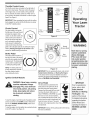
Warning: This unit is equippedwith an internalcombustionengineand shouldnot be usedon or nearany unimprovedforest-covered,brushcoveredor grass-coveredland unlesstheengine'sexhaustsystemis equippedwith a sparkarrestermeetingapplicablelocalor statelaws(if any).
If a sparkarresteris used,it shouldbe maintainedin effectiveworkingorder by the operator.In theState of Californiathe aboveis requiredbylaw
(Section4442 of the CaliforniaPublicResourcesCode). Otherstatesmay havesimilarlaws.Federallaws applyon federallands.A sparkarrester
for the muffleris availablethroughyour nearestengineauthorizedservicedealeror contactthe servicedepartment,RO. Box361131Cleveland,
Ohio 44136-0019.
PRINTEDIN U.S.A.
MTD LLC, P.O. BOX 361131 CLEVELAND, OHIO 44136-0019
FORMNO.769-02073C
01/05/2006
This Operator's Manual is an important part of your new lawn tractor, it will help you assemble,
prepare and maintain the unit for best performance.
Please read and understand what it says.
Table of Contents
Slope Gauge .......................................................
Safe Operation Practices ...................................
Setting UpYour Lawn Tractor ............................
Operating Your Lawn Tractor ...........................
Adjusting Your Lawn Tractor ............................
3
4
8
12
20
Maintaining Your Lawn Tractor ........................
Off-Season Storage / Attachments .................
Safety Labels ....................................................
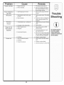
Trouble Shooting ..............................................
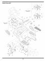
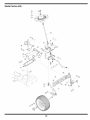
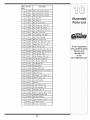
Parts List ...........................................................
24
30
31
32
34
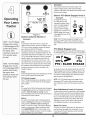
Finding and Recording Model Number
BEFOREYOU START ASSEMBLING
YOUR NEW EQUIPMENT,
please locate the model plate on the equipment and copy the
information to the sample model plate provided to the right.
You can locate the model plate by looking beneathe the seat.
This information will be necessary to use the manufacturer's
web site and/or obtain assistance from the Customer Support
Department or an authorized service dealer.
Model Number
Serial Number
MTD LLC
www.mtdproducts.com
P.O= BOX
CLEVELAND,
330-220-4683
800-800-7310
361131
OH 44136
Customer Support
Please do NOTretum
purchased,
without
the unit to the retailer from which it was
first contacting
Customer
Support.
If you have difficulty assembling this product or have any questions regardingthe controls, operation,or maintenanceof this
unit, you can seek help from the experts. Choose from the options below:
1. Visit mtdproducts.com.
Click on the Service & Support menu option.
2. Phone a Customer Support Representative at 1 (800) 800-7310.
3. The engine manufacturer is responsiblefor all engine-related issues with regards to performance, power-rating,specifications, warranty and service. Please refer to the engine manufacturer'sOwner's/Operator's Manual, packed separatelywith
your unit, for more information.
MTD/n_er_@_i®a_
Award
Wi_n i_g ?rd_s_ts
?riv®cy Pd_y
O_r Com?_ay
o_r_,qo_
_
Suppo_±
Product. Registration
Product Menu
2
O
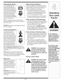
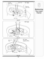
Sight and hold this levelwith a vertical tree...
o
1=
o
>:.
(13
O3
(13
(13
OO
O
(-O5
E
also
O
(13
(13
o3
(13
OO
o3
I
(13
E
(]3
(13
o
o5
(13
OO
O3
(13
-5
C5
O3
('5
O
O3
O5
(13
O
E
t"b
(13
O9
15°
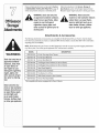
WARNING: Engine Exhaust, some of its constituents, and certain vehicle components contain or emit chemicals known to State of Californiato cause cancer and
birth defects or other reproductiveharm.
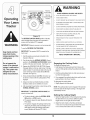
DANGER: This machine was built to be operated according to the rules for safe operation in this
manual. As with any type of power equipment, carelessness or error on the part of the operator can
result in serious injury. This machine is capable of amputating hands and feet and throwing objects.
Failureto observe the following safety instructions could result in serious injury or death.
Practices
WARNING
This symbol points
out important safety
instructionswhich, if
not followed, could
endangerthe personal
safety and/or property
ofyourself and others.
Read and follow all
I instructions in this manual before attempting to
operate this machine.
tFailureto comply with
hese instructions may
result in personal injury.
When you see this
symbol.
HEED iTS WARNING
Your
Responsibility
Restrict the use
of this power machine
to persons who read,
understand
and follow the warnings
and instructions
in this manual
Children
Operation
1. Tragicaccidentscanoccur if the operatoris not
alertto the presenceof children.Childrenare often
attractedto themachineand the mowingactivity.
Theydo not understandthe dangers.Neverassume
that childrenwill remainwhereyou last sawthem.
a. Keepchildrenout of the mowingarea and in
watchfulcare of a responsibleadultother than
the operator.
b. Be alert and turnmachineoff ifa childenters
the area.
Safe Handling of Gasoline:
1. Toavoid personalinjuryor propertydamageuse
extremecare in handlinggasoline.Gasolineis
extremely flammableand the vapors are explosive. Seriouspersonalinjurycan occurwhengasoline
isspilledon yourselfor yourclotheswhichcan ignite.
Washyourskin and changeclothesimmediately.
a. Use onlyan approvedgasolinecontainer.
b. Neverfill containersinsidea vehicleor on a
truckor trailerbed with a plasticliner.Always
c. Beforeand while backing,lookbehindand
placecontainerson the groundawayfrom
downfor smallchildren.
yourvehiclebeforefilling.
d. Nevercarry children,evenwith the blade(s)
c. Whenpractical,removegas-powered
shutoff.They mayfalloff and be seriously
equipmentfromthe truckor trailerand refuelit
injuredor interferewith safemachineoperation.
on the ground.If this isnotpossible,then
e. Use extremecarewhenapproachingblind
refuelsuch equipmenton a trailerwith a
corners,doorways,shrubs,trees or other
portablecontainer,ratherthan froma gasoline
objectsthat may blockyourvision of a child
dispensernozzle.
whomay run intothe machine.
d. Keepthe nozzlein contactwith the rimof
f. To avoid back-over accidents, always
the fueltank or containeropeningat all
disengagethe cuttingblade(s) before
timesuntilfuelingiscomplete.Donot usea
shiftinginto Reverse.if equipped,the
nozzlelock-opendevice.
"Reverse CautionMode"shouldnot be
e. Extinguishall cigarettes,cigars,pipesand
used when childrenor others are around.
othersourcesof ignition.
g. Keepchildrenaway from hotor running
f. Neverfuel machineindoors.
engines.They can sufferburnsfroma hot
g. Neverremovegas cap or add fuel whilethe
muffler.
engineishot or running.Allowengineto cool
h. Removekeywhenmachineis unattendedto
at least two minutesbeforerefueling.
preventunauthorizedoperation.
h. Neveroverfill fuel tank.Fill tank to no more
2. Neverallowchildrenunder 14 yearsold to operate
than1/2inchbelowbottomof filler neck to
the machine.Children14years old and overshould
allowspacefor fuel expansion.
readand understandthe operationinstructions
and
i. Replacegasolinecapand tighten securely.
safety rulesinthis manualand shouldbe trainedand
j. If gasolineis spilled,wipe it off theengine
supervisedbya parent.
and equipment.Moveunit to anotherarea.
Wait5 minutesbeforestartingtheengine.
k. Toreducefirehazards,keepmachinefreeof
grass,leaves,or otherdebris build-up.Clean
up oil or fuel spillageand removeanyfuel
soakeddebris.
I. Neverstorethe machineor fuel container
insidewherethere is an open flame,spark
or pilot lightas on a waterheater,space
heater,furnace,clothesdryeror other gas
appliances.
m. Allowa machineto cool at least five minutes
beforestoring.
4
....................................................
GeneralOperation:
14.Watchfor traffic whenoperatingnearor crossing
roadways.This machineis not intendedfor useon
anypublic roadway.
15.Do notoperatethe machinewhileunderthe influenceof alcoholor drugs.
16.Mowonly in daylightor good artificiallight.
17.Nevercarry passengers.
18.Disengageblade(s)beforeshiftinginto reverse.
Back up slowly.Alwayslookdownand behindbefore
and whilebackingto avoida back-overaccident.
19.Slowdownbeforeturning.Operatethe machine
smoothly.Avoiderraticoperationand excessive
speed.
20.Disengageblade(s),set parkingbrake,stopengine
and wait untilthe blade(s)cometo a completestop
beforeremovinggrass catcher,emptyinggrass,
uncloggingchute,removingany grassor debris,or
makinganyadjustments.
21.Neverleavea runningmachineunattended.Always
turnoff blade(s), placetransmissionin neutral,set
parkingbrake,stop engineand removekey before
dismounting.
22.Useextracare whenloadingor unloadingthe
machineintoa traileror truck. This unit shouldnot
be drivenup or downramp(s),becausethe unit
couldtip over,causingseriouspersonalinjury.The
unit mustbe pushedmanuallyon ramp(s)to load or
unloadproperly.
23.Mufflerand enginebecomehotand can causea
burn.Do nottouch.
1. Read,understand,and followall instructionson the
machineand in the manual(s)beforeattemptingto
assembleand operate.Keepthis manualin a safe
placefor future and regularreferenceand for ordering
replacementparts.
2. Be familiarwith all controlsandtheir properoperation.
Knowhow to stopthe machineand disengagethem
quickly.
3, Neverallowchildrenunder 14yearsold to operate
this machine.Children14years old and overshould
readand understandthe operationinstructionsand
safety rulesin this manualand shouldbe trainedand
supervisedby a parent.
4. Neverallowadults to operatethis machinewithout
proper instruction.
5. To helpavoidblade contactor a thrownobject injury,
keep bystanders,helpers,childrenand petsat least
75 feet fromthe machinewhileit is in operation.Stop
machineif anyoneenters thearea.
6. Thoroughlyinspectthearea wheretheequipmentis to
be used. Removeall stones,sticks,wire,bones,toys,
and otherforeignobjectswhichcouldbe pickedup
and thrown bythe blade(s).Thrownobjectscancause
seriouspersonalinjury.
7. Planyourmowingpatternto avoiddischargeof
materialtowardroads,sidewalks,bystandersand the
like. Also,avoiddischargingmaterialagainsta wall or
obstructionwhich maycause dischargedmaterialto
ricochetback towardthe operator.
8. Alwayswear safetyglassesor safetygogglesduring
24.Checkoverheadclearancescarefullybeforedriving
operationand while performingan adjustmentor
under lowhangingtreebranches,wires,dooropenrepairto protectyoureyes.Thrownobjectswhich
ingsetc., wheretheoperatormaybe struckor pulled
ricochetcancause seriousinjuryto the eyes.
fromthe unit,which couldresult in seriousinjury.
9. Wearsturdy,rough-soledwork shoesand close-fitting 25.Disengageall attachmentclutches,depressthe
slacks and shirts. Loosefittingclothesandjewelry
brakepedalcompletelyand shift into neutralbefore
can be caught in movableparts.Neveroperatethis
attemptingto startengine.
machinein barefeet or sandals.
26.Yourmachineisdesignedto cut normalresidential
10.Be awareof the mowerand attachmentdischarge
grassof a heightno morethan 10".Do notattemptto
directionand do not pointit at anyone.Donot operate
mowthroughunusuallytall, dry grass (e.g.,pasture)
the mowerwithoutthe dischargecoveror entiregrass
or pilesof dry leaves.Dry grass or leavesmay
catcherin its properplace.
contactthe engineexhaustand/orbuild up on the
mowerdeck presentinga potentialfire hazard.
11.Donot put handsor feet near rotatingpartsor under
27.Use onlyaccessoriesand attachmentsapprovedfor
the cuttingdeck. Contactwith the blade(s)can
amputatehandsand feet.
this machinebythe machinemanufacturer.Read,
understandand followall instructionsprovidedwith
12.A missingor damageddischargecovercan cause
the approvedaccessoryor attachment.
blade contactor thrown objectinjuries.
13.Stop the blade(s)whencrossinggraveldrives,walks, 28.Data indicatesthat operators,age 60 yearsand
above,are involvedin a largepercentageof riding
or roadsand whilenot cuttinggrass.
mower-relatedinjuries.Theseoperatorsshould
evaluatetheirability to operatethe ridingmower
safelyenoughto protectthemselvesand othersfrom
seriousinjury.
29.If situationsoccurwhich are not coveredin this
manual,usecareand good judgment.Contactyour
customerservicerepresentativefor assistance.
WARNING
This symbol points
out important safety
instructions which, if
not followed, could
endanger the personal
safety and/or property
of yourself and others.
Read and follow all
instructions in this manual before attempting to
operate this machine.
Failureto comply with
these instructions may
result in personal injury.
When you see this
symbol.
HEED ITS WARNING
Your
Responsibility
Restrictthe use
of this power machine
to persons who read,
understand
and follow the warnings
and instructions
in this manual
5
Thissymbolpoints
outimportant
safety
instructions
which,if
notfollowed,could
endanger
thepersonal
i safetyand/orproperty
ofyourselfandothers.
Readandfollowall
instructions
inthismanualbeforeattempting
to
I operatethismachine.
I Failuretocomplywith
theseinstructions
may
i resultin personal
injury.
Whenyouseethis
symbol.
Slope Operation:
Do Not:
Slopesare a majorfactor relatedto loss of controland
tip-overaccidentswhich can resultin severeinjuryor
death.All slopesrequireextracaution.If youcannot
back up the slopeor if youfeel uneasyon it, do notmow
it.
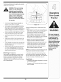
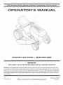
Foryour safety,usethe slopegaugeincludedas partof
this manualto measureslopesbeforeoperatingthis unit
on a slopedor hillyarea. If the slopeis greaterthan 15
degreesas shownon theslopegauge,do notoperate
this unit on that area or seriousinjurycouldresult.
DO:
1. Do notturn on slopesunlessnecessary;then,turn
slowlyand graduallydownhill,if possible.
2. Do not mownear drop-offs,ditchesor embankments.
Themowercouldsuddenlyturnoverif a wheel is over
the edgeof a cliff, ditch,or if an edge cavesin.
3. Do nottry to stabilizethe machineby puttingyourfoot
on the ground.
4. Do not usea grasscatcheron steep slopes.
5. Do not mowon wet grass. Reducedtractioncould
causesliding.
6. Do not shiftto neutraland coastdownhill.Over-speeding may causethe operatorto losecontrol of the
machineresultingin seriousinjuryor death.
7. Do nottow heavy pull behindattachments(e.g.loaded
dumpcart, lawnroller,etc.)on slopesgreaterthan
5 degrees.Whengoingdown hill,the extra weight
tendsto pushthe tractorand may causeyou to loose
control.(e.g. tractormayspeedup, brakingand steering ability are reduced,attachmentmayjack-knifeand
causetractorto overturn).
1. Mow up and downslopes,notacross. Exercise
extremecautionwhenchangingdirectionon slopes.
2. Watchfor holes, ruts,bumps,rocks,or other hidden
objects.Uneventerraincouldoverturnthe machine.
Tallgrasscan hide obstacles.
3. Use slow speed.Choosea low enoughspeed
settingso that youwill not haveto stopor shift while
on the slope.Tires may losetractionon slopeseven
thoughthe brakesare functioningproperly.Always
keepmachinein gear whengoingdown slopesto
take advantageof engine brakingaction.
4. Followthe manufacturer'srecommendations
for
wheelweightsor counterweightsto improvestability.
5. Use extracare with grasscatchersor otherattachments.Thesecanchangethe stabilityof the
machine.
Towing:
1. Towonlywith a machinethat hasa hitch designedfor
towing.Donot attachtowedequipmentexceptat the
hitch point.
2. Followthe manufacturersrecommendationfor weight
limitsfor towedequipmentand towingon slopes.
3. Neverallowchildrenor othersin or on towedequipment.
6. Keepall movementon the slopesslowand gradual.
Do not makesuddenchangesin speedor direction.
Rapidengagementor brakingcouldcausethe front
of the machineto lift and rapidlyflip overbackwards
whichcouldcause seriousinjury.
7. Avoidstartingor stoppingon a slope.If tires lose
traction,disengagethe blade(s)and proceedslowly
straightdownthe slope.
4. On slopes,the weightof the towedequipmentmay
causeloss of tractionand loss of control.
5. Travelslowlyand allowextra distanceto stop.
6. Do not shiftto neutraland coastdownhill.
i HEED ITSWARNING
Your
i Responsibility
Restrict the use
of this power machine
to persons who read,
understand
and follow the warnings
and instructions
in this manual
6
Service
10.Neverattemptto makeadjustmentsor repairsto the
machinewhilethe engine isrunning.
1. Neverrun an engineindoorsor in a poorlyventilated
11.Grasscatchercomponents
and the discharge
area. Engineexhaustcontainscarbonmonoxide,an
coverare
subjectto
wearand
damagewhich could
odorless,and deadlygas.
exposemovingpartsor allowobjectsto be thrown.
2. Beforecleaning,repairing,or inspecting,makecertain
Forsafety protection,frequentlycheckcomponents
the blade(s)and all movingparts havestopped.
and replaceimmediatelywith originalequipment
Disconnectthe sparkplug wireand groundagainstthe
manufacturer's(O.E.M.)parts only,listed in this
engineto preventunintendedstarting.
manual."Useof parts which do not meetthe original
3. Periodicallycheckto make surethe bladescome to
equipmentspecificationsmay leadto improper
completestop withinapproximately(5) five seconds
performanceand compromisesafety!"
after operatingthe bladedisengagementcontrol.If the
12.Do notchangethe enginegovernorsettingsor
bladesdo notstop within thethis timeframe,yourunit
over-speedthe engine.Thegovernorcontrolsthe
shouldbe servicedprofessionallyby an authorized
maximumsafe operatingspeedof the engine.
MTDServiceDealer.
13.Maintainor replacesafety and instructionlabels,as
4. Checkbrakeoperationfrequentlyas it is subjectedto
necessary.
wearduring normaloperation.Adjustand serviceas
14.Observeproperdisposallawsand regulationsfor
required.
gas, oil,etc. to protecttheenvironment.
5. Checkthe blade(s)and enginemountingbolts at
frequentintervalsfor propertightness.Also,visually
inspectblade(s)for damage(e.g.,excessivewear,
bent, cracked). Replacethe blade(s)with theoriginal
equipmentmanufacturer's(O.E.M.)blade(s)only,
listed inthis manual."Useof partswhich do not meet
the originalequipmentspecificationsmaylead to
improperperformanceand compromisesafety!"
6. Mowerbladesare sharp.Wrapthe bladeor wear
gloves,and useextra cautionwhenservicingthem.
7. Keepall nuts, bolts,and screwstight to be surethe
equipmentis insafe workingcondition.
8. Nevertamperwith the safety interlocksystemor other
safety devices.Checktheir properoperationregularly.
9. After strikinga foreignobject,stop the engine,
disconnectthe spark plug wire(s)and groundagainst
the engine.Thoroughlyinspectthe machinefor any
damage.Repairthe damagebeforestartingand
operating.
This symbol points
out important safety
instructions which, if
not followed, could
endangerthe personal
safety and/or property
of yourselfand others.
Read and follow all
instructions in this manual before attempting to
operate this machine.
Failureto comply with
these instructions may
result in personal injury.
When you see this
symbol.
HEED iTS WARNING
Your
Responsibility
Restrictthe use
of this power machine
to personswho read.
understand
and follow the warnings
and instructions
in this manual
7
NOTE:This OperatorsManualcoversa rangeof product
specificationsfor variousmodels.Characteristicsand featuresdiscussedand/orillustratedin this manualmay not
be applicableto all models.MTDLLCreservesthe right
to changeproductspecifications,designsand equipment
withoutnotice and withoutincurringobligation.
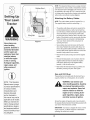
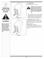
RubberBoot
Attaching
the Battery
Cables
NOTE:Thepositivebatteryterminalis markedPos. (+).
Thenegativebatteryterminalis markedNeg. (-).
Tractor
•
Thepositivecable(heavy redwire) is securedto the
positivebatteryterminal(+)with a hexbolt and hex
nut at thefactory.Beforeattachingthe negativecable,
removethe batteryby removingthe positivecable
and hold-downstrap.Notethe dateon the sideof the
battery.Ifthe batteryis putinto serviceafter this date,
chargethe batteryas instructedin the Maintaining
YourLawnTractorsectionof this manualprior to
operatingthetractor.
•
Securebatteryback ontothe tractorwith the holddownstrap.Reattachthe positivecable (heavyred
wire)to the positivebatteryterminal(+)with the bolt
and nut. Makecertain that the rubberbootcoversthe
terminalto help protectit fromcorrosion.
explosive: Never fuel
machine indoors
•
Removethehex boltand wing nutfrom the negative
cable.
or while the engine
is hot or running,
Extinguish cigarettes,
cigars, pipes, and
•
Removetheblack plasticcover,if present,from the
negativebatteryterminaland attachthe negative
cable(heavy blackwire)to the negativebattery
terminal(-) withthe bolt and nut.
•
Makecertain thehold-downstrap is in positionover
the battery,securingit in place. See Figure1.
Use extreme care
Figure 1
when
handling
gaso nel
Gasoline
extremely flammable
and the vapors are
other
sources
of
ignitionl
Gas and Oil Fill-up
Thegasolinetank is locatedunderthe hood and hasa
capacityof eithertwo or threegallons.Do notoverfill.
WARNING: Use extreme care
NOTE: This Operators
when handling gasoline. Gasoline
is extremely flammable and the
vapors are explosive. Never fuel
machine indoors or while the
Manual Coversa range
of produCtspecifications
for VariousmodelS:
Characteristics and
featuresdiscussed
and/or illustrated in
i
engine is hot or running. Extinguish cigarettes, cigars, pipes,
and other sources of ignition.
s manualmay not
applicable toall models:
MTD LLC reservesthe
Servicethe enginewith gasolineand oil as instructedin
the separateEngineOperator/OwnerManualpackedwith
yourtractor.Readinstructionscarefully.
right to change product
specifications, (Jesigns
and equipment without
notice and without incur-
IMPORTANT:Yourtractoris shippedwith motoroil in the
engine.However,you MUSTcheckthe oil levelbefore
operating.Be careful notto overfill.
i[ing obligatiOnl
8
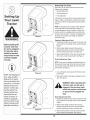
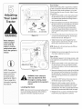
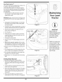
Shipping
Brace Removal
f
WARNING: Make sure the riding
mower's engine is off, remove the
ignition key, and set the parking
brake before removing the shipping brace.
•
TractOr
Locatethe shippingbrace,ifpresent,and accompanyingwarningtag foundon the rightside of the mower,
betweenthe dischargechuteand thecuttingdeck.
See Figure2.
• Whileholdingthe dischargechute with yourleft hand,
removethe shippingbracewith your righthandby
graspingitbetweenyour thumband indexfingerand
rotatingitclockwise.
Figure 2
WARNING: The shipping brace,
used for packaging purposes
only, must be removed and discarded before operating your
riding mower.
Make sure the riding
mower's engine is
off, remove the ignition key, and set the
parking brake before
removingthe shipping
brace.
WARNING: The mowing deck is
capable of throwing objects. Failure to operate the riding mower
without the discharge cover in the
proper operating position could
result in serious personal injury
and/or property damage.
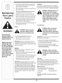
Attaching
The Steering
WARNING
The shipping brace,
used for packaging
purposes only, must
be removed and
discarded before
operating your riding
mower.
Wheel
If the steeringwheelforyour tractordid notcome
attached,the hardwarefor attachingit hasbeen packed
within the steeringwheel,beneaththe steeringwheel
cap. Carefullypry off the steeringwheelcapand remove
the hardware.
Figure 3
The mowing deck is
capable of throwing
objects. Failure to
operate the riding
mower without the
discharge cover in
the proper operating
position could result
in serious personal
injury and/or property
damage.
NOTE:Thereare two differentstylesof steeringwheel
cap. See Figure3. Styles vary by model.
1. With the wheels of the tractor pointingstraight
forward, placethe steeringwheeloverthe steering
shaft.
2. Placethe washer(with thecuppedsidedown)over
the steeringshaftand securewith the hex bolt. See
Figure3.
3. Placethe steeringwheelcap overthe centerof the
steeringwheeland pushdownwarduntilit"clicks"into
place.
9
Attaching
The Seat
Seatstyles vary bytractormodeland thereare three
differentstyles available:
• StandardAdjustment
•
QuickAdjustment&
•
KnobAdjustment
If the seatfor yourtractordid notcome attached,referto
Figure4, Figure5, and Figure6 to identifyyourtractor's
seat styleand followthe applicableinstructionsbelowto
attachit.
Figure 4
WARNING
NOTE:Forshippingreasons,seatsare eitherfastened
to the tractorseat'spivot bracketwith a plastictie, or
mountedbackwardto the pivot bracket.Ineithercase,
freethe seat form its shippingpositionand removethe
two hex screws(or knobs,on modelsso equipped)from
the bottomof seatbeforeproceedingwith applicable
instructionsbelow.
Standard Adjustment Seat
1. Positionthe shoulderscrews(foundon the baseof the
seat) insidetheslot openingsin the seat pivot bracket.
Figure4.
Before operatingthis
machine,make sure
the seat is engaged in
the seat stop; stand
2. Slide the seatslightlyrearwardin the seat pivot
bracket,liningup the rearslots in the pivot bracket
with the remainingtwo holesin the seat'sbase.
and
pu,back
onseat
3. Selectdesiredpositionforthe seat,and securewith
the two hex screwsremovedearlier.See Figure4.
behind
themachine
fu,yengaged
Quick Adjustment Seat
intostop:
NOTE:If your seatwas shippedmountedbackwardson
the seat pivotbracket,pull outthe tab foundon the seat
stop and hold it open whileslidingthe seatoff the seat
pivot bracket.See Figure5.
Figure 5
NOTE: Forsh pping rea:
s0nsl Seatsareeither
1. Line up the plasticseat spacerswith the slotsin seat
pivot bracket.
2. Slide seat in untilfront seat spacerengagesthe seat
stop.See Figure5.
fastenedto the tractor
seat's pivot braCketWitt
a plastiCtie, or mounted
WARNING" Before operating this
machine, make sure the seat is
engaged in the seat stop, stand
behind the machine and pull back
on seat until fully engaged into
stop.
backward to the pivot
bracket. In either case;
free the seat form its
shipping p0sition and
remove the two Box
screws (or knobsion
Knob Adjustment Seat
1. Positionthe shoulderscrews(foundon the baseof the
seat) insidetheslot openingsin the seat pivot bracket.
Figure6.
models so equipped)
from thebottom of seat
before proceedingwith
applicable instructions:
Figure 6
2. Slide the seatslightlyrearwardin the seat pivot
bracket,liningup the rearslots in the pivot bracket
with the remainingtwo holesin the seat'sbase.
3. Selectdesiredpositionforthe seat,and securewith
the two knobs removedearlier.See Figure6.
10
NOTE: Referto Mulching on page 19for moredetailed
information.
LaWn
Tractor
If you'dpreferto operatethe cuttingdeck withoutmulching, simplyremovethe mulch plugby unthreadingthe
plasticwing nutwhich fastensit to the cuttingdeck.This
will allowthe clippingsto dischargeout of the discharge
openingduringoperation.See Figure7.
Figure 7
WARNING
i
i
i
ii i _iI_ ii
11
i
i
i
ii
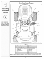
Know Your Lawn Tractor
G
H
NOTE: Any reference
in this manual to the
RIGHTor LEFT side of
the tractor is observed
J
B
from operator's position.
K
C
@
@
D
f"
"_
L
E
M
F
NOTE:Steeringwheelnot shownfor clarity
Figure 8
A
PTO(Blade Engage)Levert
G
ThrottleLever
PTO(Blade Engage)Knobt
H
CruiseControl Button
B
SystemsIndicatorMonitort/Ammeter I
IgnitionSwitchModule
C
ChokeKnobt
J
BrakePedal
D
ParkingBrakeButton
K
DrivePedal
E
Shift Lever
L
DeckLift Lever
F
CupHolder
M
SeatAdjustmentLevert
If soequipped
NOTE:Anyreferencein this manualto the RIGHTor LEFTside of the tractoris observedfrom operator'sposition.
12
Throttle
Control
f
Lever
Thethrottlecontrol leveris locatedon the rightside of
thetractor'sdash panel.This levercontrolsthe speed
of the engineand,on somemodels,when pushedall
theway forward,the chokecontrol also.Whenset in a
givenposition,the throttlewill maintaina uniformengine
speed.See Figure9.
Fast
Position
Choke__-_).
Position
Fast
Position
Operating
Your LaWn
IMPORTANT:Whenoperatingthetractorwith the cutting
deck engaged,be certainthat the throttleleveris always
in the FAST(rabbit)position.
Choke
Control
Slow
Position
On some models,movingthe
throttleleverall the way forward
activatestheengine'schoke
control.On all othermodels,the
chokecontrolcan be foundon
the left side of thedash panel
and is activatedby pullingthe
knoboutward.Activatingthe
chokecontrolclosesthe choke
plateon the carburetorand aids in startingthe engine.
Referto Starting The Engine in this sectionof the
manualfor detailedstartinginstructions.
Brake
Pedal
Slow --->
Position
Figure 9
f
ii?i?ii!:ii ¸C :L
Normal
Mode
Ignition
Switch
Start
Position
[
Module
WARNING: Never leave a running
machine unattended, Always
disengage PTO, move shift lever
into neutral position, set parking
brake, stop engine and remove
key to prevent unintended
starting,
WARNING
Never leave a running
machine unattended,
Position
The brakepedal islocatedon /
the rightfront sideof the tractor_
abovethe drive pedalalongthe
runningboard.The brakepedal
can be usedfor suddenstops
or settingthe parkingbrake.
NOTE:Thebrakepedal must
be fully depressedto activate
the safetyinterlockswitch
whenstartingthe tractor.
i!iiC !i ¸
Always disengage
PTO, move shift lever
nto neutral position,
set Parking brake, stop
engine and remove key
to prevent unintended
starting:
Figure 10
IMPORTANT:Priorto operatingthe tractor,referto both
Safety Interlock Switches and Starting The Engine
inthis sectionof the manualfor detailedinstructions
regardingthe IgnitionSwitchModuleand operatingthe
tractorin REVERSECAUTIONMODE.
Drive Pedal
The drivepedal is locatedbelowthe
brakepedalon the rightfront side of
the tractoralongthe runningboard.
Depressthe drivepedal with yourright
foot whenthe tractorshift leveris in
either FORWARDor REVERSEtocaus_
the tractorto move.Groundspeedis
also controlledwith the drivepedal.The
furtherdown thepedal is depressed,the
fasterthe tractorwill travel.Thepedal
will returnto its original positionwhen it'._
notdepressed.
IMPORTANT
Prior
tooRerating
the
tractor,refer to both
Safety interlock
Switches and Starting
M
/
4
Tostart theengine,insertthe key intothe ignitionswitch
and turnclockwiseto the STARTposition.Releasethe
key intothe NORMALMOWINGMODEpositiononce
theengine hasfired.
Tostop the engine,turn theignitionkey counterclockwise IMPORTANT:Alwaysset the parkingbrakewhenleaving
to the OFF position.See Figure10.
the tractorunattended.
13
The Engine in this
seCtion ofthe manual
for detailed instructions
i
regardingthe Ign tion
SwitCh ModUleand
operating the tractoi in
REVERSE CAUTION
MODE:
f
"_
"-\
BATT.
OIL
Ammeter
Theammetermeasuresthe electricaloutput of the
engine'schargingsystem.Undernormaloperating
conditions,with engineat full throttle,the ammetershould
indicatepositivecharge.
/z
Electric
[
///
Tractor
ii_i_i i iii_ii iii_iII ii!iii_i_
_IIIi i_i
Equipped)
Toengagethe powerto
the cuttingdeck or other
(separatelyavailable)attachmentson modelsequipped
with an electric PTO,pull
outwardon the PTO(Blade
Engage)knob.Pushthe PTO
(Blade Engage)knobinward
to disengagethe powerto the
cuttingdeck.
42.0
HOURS
1/1 0 \\\
PTO / BLADE
PARKING
,.®
®
J
Figure 11
Systems Indicator
Equipped)
NOTE: The PTO (Blade
Engage) knob must be
in the disengaged (OFF)
position when starting
the engine, when
traveling in reverseand
ifthe operator leaves
the seat.
NOTE: The PTO (Blade
Engage) lever must be
in the disengaged (OFF)
3ositionwhen starting
the engine, when
traveling tn reverseand
if the operator leaves
the seat.
Monitor
(if
LCD
Locatedin the centerof the tractor'sconsole,the
systemsindicatormonitorrecords,and displays on its
LCD,hoursof tractoroperationwheneverthe ignition
key is rotatedout of the STOPposition.
The IndicatorMonitorwill also remindthe operatorof
maintenanceintervalsfor changingthe engineoil. The
LCDwill alternatelyflashthe recordedhours,"CHG"and
"OIL"for five minutes,after every50 hoursof recorded
operationelapse.The maintenanceintervallastsfor
two hours(from 50-52,100-102,150-152,etc.). The
LCDwill alsoflash as describedabovefor five minutes
everytime the tractor'sengine hasbeen startedduring
this maintenanceinterval.Beforethe intervalexpires,
changethe crankcaseoil levelas instructedin this
Operator'sManual.
Brake
If the Brakelight illuminateswhenattemptingto start the
tractor'sengine,depressthe brakepedal.
PTO (Blade Engage)
if the PTOlightilluminateswhenattemptingto start the
tractor'sengine,movePTOleverintothe disengaged
(OFF) position.
PTO (Blade
Engage)
Knob (If
|
NOTE:The PTO(BladeEngage)knobmustbe in the
disengaged(OFF) positionwhen startingthe engine,
whentravelingin reverseand if the operatorleavesthe
seat.
PTO (Blade Engage)
Lever
On modelsequippedwith a manualPTO(Blade Engage),
the PTO(Blade Engage)leveris locatedon the left sideof
!
ON 1z
OFF
PTO /BLADE
!PTO
ENGAGE
the dashboardnext to the steeringwheel.Movethe PTO
(Blade Engage)leverforwardto engagethe powerto the
cuttingdeckor other(separatelyavailable)attachments;
movethe PTO(Blade Engage)leverrearwardto disengage thepowerto the attachments.
NOTE:The PTO(BladeEngage)levermust be in the
disengaged(OFF) positionwhen startingthe engine,
whentravelingin reverseand if the operatorleavesthe
seat.
Oil
It isnormalforthe Oil lightto illuminate
whilethe engine
iscranking duringstart-up,but ifit illuminate'sduring
operation,while the engine is running,stop the
tractorimmediatelyand checkthe crankcaseoil levelas
instructed
in this Owner'sManual.
Battery
It is normalforthe Batterylightto illuminatewhilethe
engineis cranking duringstart-up,but if it illuminate's
duringoperation,while the engineis running,the
batteryis in needof a chargeor the engine'scharging
systemis notgeneratingsufficientamperage.Refer
to the MAINTENANCEsectionof this manualfor the
properbatterychargingprocedureor havethe charging
systemcheckedby yourservicedealer.
Seat Adjustment
Lever (If Equipped)
Toadjustthe seat forwardor backwardon unitsequipped
with a quick-adjustseat,slidethe seatadjustmentlever
to the left and repositionthe seatto the desiredposition.
Oncea comfortablepositionis found,releasethe seat
adjustmentleverto lockthe seatin place. Referto the
AdjustingYour LawnTractorsectiond this manualfor
moredetailedinstructionson all seatadjustments.
Deck Lift Lever
Foundon yourtractor'srightfender,the deck lift leveris
usedto changethe heightof the cuttingdeck.To use,
movethe leverto the left,then placein the notchbest
suitedfor yourapplication.
14
Parking
Brake Button
Safety
Toset the parkingbrake,fully
depressthe brakepedal and
pushthe parkingbrakebutton in.
Holdthe button in whiletaking
yourfoot off the brakepedal.Both
the parkingbuttonand the brake
pedalwill then staydepressed.
To releasethe parkingbrake,
depressthe brakepedal slightly.
The parkingbrakebuttonwill then
returnto its originalposition.
• The enginewill automaticallyshutoff if the operator
leavesthe seat beforeengagingtheparkingbrake.
Models with Manual PTO (Blade Engage)
• The enginewill automaticallyshutoff if the operator
leavesthe tractor'sseatwith the PTO(Blade Engage)
leverin the engaged(ON) position,regardlessof
whetherthe parkingbrakeis engaged.
IMPORTANT:Alwaysset the parkingbrakewhen leaving
thetractor unattended.
Button
Thecruise controlbutton is
locatedon the tractordash
panelto the left of the ignition
switch.Pushthe cruisecontrol
buttonwhiletravelingforwardat a
desiredspeed.Whileholdingthe
buttonin, releasepressurefrom
thedrive pedal.Thiswill engage
thecruise controland allowthe
tractorto remainat that speed
withoutapplyingpressureto the
drivepedal.Depressthe brake
pedalor the drivepedalto deactivatecruisecontrol.
Referto Setting the Cruise Control laterin this section
the manualfor detailedinstructionsregardingthecruise
controlfeature.
Switches
• The safetyinterlocksystempreventsthe engine
from crankingor startingunlessthe parkingbrake
isengaged,and the PTO(Blade Engage)knob (or
lever)is in the disengaged(OFF)position.
NOTE:Theparkingbrakemust be set if the operator
leavesthe seatwith the engine runningor theengine will
automaticallyshutoff.
Cruise Control
Interlock
This tractorisequippedwith a safetyinterlock
system
for the protectionof the operator.Ifthe interlocksystem
shouldevermalfunction,do notoperatethe tractor.
Contactan authorizedMTDservicedealer.
• With the ignitionkey in the NORMALMOWING
position,the enginewill automaticallyshut off if the
PTO(Blade Engage)leveris movedinto theengaged
(ON)positionwith the shift leverin Reverse.
Models with Electric PTO (Blade Engage)
• The electricPTO(BladeEngage)clutchwillautomatically shut off if the operatorleavesthetractor'sseat
with the PTO(Blade Engage)knob in the engaged
(ON)position,regardlessof whetherthe parking
brakeis engaged.
• With the ignitionkey in the NORMALMOWING
position,the electricPTO(Blade Engage)clutchwill
automaticallyshut off if the PTO(Blade Engage)knob
is movedintothe engaged(ON) positionwith the shift
leverin Reverse.
WARNING: Do not operate the
tractor if the interlock system
is malfunctioning, This system
was designed for your safety and
protection.
NOTE:Cruisecontrolcan NOTbe engagedat the
tractor'sfastestgroundspeed. If the operatorshould
attemptto do so, the tractorwill automaticallydecelerate
to the fastestoptimalmowinggroundspeed.
Reverse
Caution
Mode
Shift Lever
WARNING: Use extreme caution
The shiftleverislocatedon the
left side of the fenderand has
threepositions,FORWARD,
NEUTRALand REVERSE.The
brakepedalmust be depressed
and the tractormustnot be in
motionwhenthe movingshift
lever.
while operating the tractor in
the REVERSE CAUTION MODE.
Always look down and behind
before and while backing. Do not
operate the tractor when children
or others are around, Stop the
tractor immediately if someone
enters the area.
IMPORTANT:Neverforce the
shift lever.Doingso may resultin
seriousdamageto the tractor's
transmission.
15
WARNING
Do not operate the
tractor if the interlock
system is malfunctioning. This system was
designed for your
safety and protection.
Use extreme caution
while operating the
tractor in the REVERSE
CAUTION MODE.
Always look down and
behind before and
while backing. Do not
operate the tractor
when children or others are around. Stop
the tractor immediately
f someone enters the
area.
f
G
Reverse
.Push Button
indicator
Light
AVOID SERIOUS iNJURY OR DEATH
Reverse
Caution Mode
Position
Stop
Position
©
Start
Position
•
GO UP AND DOWNSLOPES,NOT ACROSS.
•
AVOID SUDDENTURNS.
•
DO NOT OPERATETHE UNITWHERE IT COULDSLIP OR TIP.
•
IF MACHINE STOPSGOINGUPHILL,STOP BLADE(S) AND
BACK DOWNHILLSLOWLY.
•
DO NOT MOWWHEN CHILDRENOR OTHERSARE AROUND.
•
NEVER CARRYCHILDREN,EVENWITH BLADESOFF.
•
LOOK DOWNAND BEHINDBEFOREAND WHILE BACKING.
•
KEEP SAFETY DEVICES(GUARDS,SHIELDS,AND
SWITCHES) IN PLACE ANDWORKING.
Figure 12
•
The REVERSECAUTIONMODE positionof the key
switchmoduleallowsthetractorto be operatedin
reversewith the blades(PTO)engaged.
WARNING
BLADE(S).
IMPORTANT:Mowingin reverseis not recommended.
Do not operate the
tractor if the interlock
system is malfunctioning. This system was
designed for your
safety and protection.
•
KNOW LOCATIONAND FUNCTIONOF ALL CONTROLS.
•
BE SUREBLADE(S) AND ENGINEARE STOPPEDBEFORE
PLACING HANDSOR FEET NEAR BLADE(S).
Tousethe REVERSECAUTIONMODE:
Keep hands and feet
away from the discharge opening of the
cutting deck.
REMOVEOBJECTSTHAT COULD BETHROWNBYTHE
•
BEFORE LEAVINGOPERATOR'SPOSITION,DISENGAGE
BLADE(S), PLACETHE SHIFT LEVER IN NEUTRAL,ENGAGE
IMPORTANT:TheoperatorMUSTbe seatedin the
tractorseat.
BRAKE LOCK, SHUT ENGINEOFF AND REMOVEKEY.
READ OPERATOR'S
MANUAL
1. Start the engineas previouslyinstructedin this
Operator'sManual.
2. Turnthe key from the NORMALMOWING(Green)
positionto the REVERSECAUTIONMODE(Yellow)
positionof the key switchmodule. See Figure12.
3. Depressthe REVERSEPUSHBUTTON(Orange,
TriangularButton)at the top, rightcornerof the key
switchmodule.The red indicatorlight at thetop, left
cornerof the keyswitch modulewill be ON while
activated.See Figure12.
4. Onceactivated(indicatorlightON), thetractorcan
be drivenin reversewith the cuttingblades(PTO)
engaged.
5. Alwayslookdownand behindbeforeand while
backingto makesureno childrenare around.
6. After resumingforwardmotion,returnthe keyto the
NORMALMOWINGposition.
IMPORTANT:The REVERSECAUTIONMODE will
remainactivateduntil:
Engaging
Brake
2. Holdthe parkingbrakebutton in while removingyour
foot fromthe brakepedal.
3. Onceengaged,the parkingbrakebuttonand the brake
pedalwill lock in the "down"position.
Todisengagetheparkingbrake:
1. Slightlydepressthe brakepedal.
NOTE:Theparkingbrakemustbe engagedif the operator
leavesthe seatwith the engine runningor theengine will
automaticallyshutoff.
Setting
a. Thekey is placedin eitherthe NORMALMOWING positionor STOPposition.
b. Theoperatorleavesthe seat (Modelswith Electric
PTOONLY).
c. Theoperatorengagesthe parkingbrakeby fully
depressingthe brakepedal and holdingit down
whilegentlypushingthe parkingbrakebutton
inward(Modelswith ManualPTOONLY).
the Parking
Toengagethe parkingbrake:
1. Fullydepressthe brakepedaland hold it downwith
yourfoot whilegently pushingthe parkingbrakebutton
inward.
the Cutting
Height
1. Selectthe heightpositionof the cuttingdeck by placing
the deck lift leverin anyof the six differentcutting
heightnotcheson the rightsideof the fender.
2. Adjustthe deck wheelsso that theyare between
1A-inchand V2-inchabovethe groundwhen thetractor
is on a smooth,flat surfacesuch as a driveway.
16
,_
away
from the
discharge
opening
WARNING:
Keep
hands and
feet
Stopping
the Engine
of the cutting deck.
,_
WARNING: If you strike a foreign
object, stop the engine, discon-
NOTE:Thedeck wheelsare an anti-scalpfeatureof the
deck and are not designedto supportthe weightof the
cuttingdeck.
A
_
nect the spark plug wire(s) and
ground against the engine.
Referto Leveling the Deck on page 20 of this manual
for moredetailedinstructions
regardingvariousdeck
adjustments,
Thoroughly inspectthe machine
for any damage. Repair the
damage before restarting and
Starting
operating
the Engine
Operating
Your LaWn
1. If the bladesare engaged,placethe PTO(Blade
_
tractor
if theDo
interlock
system
WARNING:
not operate
theis
malfunctioning. This system was
designed for your safety and
position.
Engage)knob (or lever)in the disengaged(OFF)
2. Turnthe ignitionkeycounterclockwiseto the STOP
protection.
3. Removethe key fromthe ignitionswitchto prevent
unintendedstarting.
position.
NOTE:Referto theTRACTORSET-UPon page8 of this
WARNING
Driving The Tractor
manualfor Gasolineand Oil fill-up instructions.
1. Insertthe tractorkey intothe ignitionswitch.
2. Placethe PTO(Blade Engage)knob(or lever)in the
A_
WARNING: Avoid sudden starts,
disengaged(OFF) position.
3. Engagethe tractor'sparkingbrake,
_
ex-cessive speed and sudden
stops.
4. Activatethe chokecontrol.
5. Turnthe ignitionkey clockwiseto the STARTposition.
Afterthe engine starts,releasethe key.Itwill returnto
the ON position,
IMPORTANT:DoNOThold the key in the STARTpositionfor longerthanten secondsat a time.Doingso may
causedamageto your engine'selectricstarter,
WARNING: Do not leave the seat
of the tractor without first placing
the PTO (Blade Engage) knob (or
lever) in the disengaged (OFF)
position, depressing the brake
pedal and engaging the parking
brake, if leaving the tractor
6. Afterthe engine starts,deactivatethechokecontrol
and placethe throttlecontrol inthe FASTposition,
unattended, also turn the ignition
key off and remove the key.
NOTE:Do NOTleavethe chokecontrolon while operatingthe tractor.Doingso will resultina "rich"fuel mixture
and causethe engineto run poorly,
1. Depressthe brakepedal to releasethe parkingbrake
and letthe pedalup.
2. Movethe throttleleverintothe FAST(rabbit)position.
IMPORTANT:Do NOTuse the shiftleverto changethe
directionof travel whenthetractoris in motion.Always
usethe brakepedalto bringthe tractorto a complete
stop beforeshifting.
3. Tomoveforward,placethe shift leverinthe FORWARDposition,thenslowlydepressthe drivepedal
untilthe desiredspeedisachieved.
17
if you strike a foreign
object, stop the
engine, disconnect
the spark plug wire(s)
and ground against
the engine. Thoroughly
inspectthe machine
for any damage. Repair
:he damage before
restarting and operating.
Avoid sudden starts,
ex-cessive speed and
sudden stops.
Do not leave the seat
of the tractor without
first placingthe PTO
(Blade Engage) knob
(or lever) in the disengaged (OFF) position,
depressing the brake
pedal and engaging
the parking brake, if
leaving the tractor
unattended, also turn
the ignition key off and
remove the key.
4. Tomovein reverse,placethe shiftleverin the
REVERSEposition,checkthat thearea behindis
clearthen slowlydepressthe drivepedal.
Disengagethecruise controlusingone of the following
methods:
Driving On Slopes
2. Lightlydepressthe drivepedal.
Referto the SLOPEGAUGEon page3 to help determineslopeswhereyou mayoperatethe tractorsafely.
Operating
Your Lawn
_
inclineswithDo
a slope
in excess
WARNING"
not mow
on
of 15 degrees (a rise of approximately 2-1/2 feet every 10feet).
The tractor could overturn and
cause serious injury.
• Mow up and downslopes,NEVERacross.
• Exerciseextremecautionwhenchangingdirection
on slopes.
WARNING
Do not mow on inclines
with a slope in excess
of 15 degrees (a rise
of approximately 2-1/2
feet every 10feet). The
tractor could overturn
and cause serious
injury.
To help avoid blade
contact or a thrown
object injury, keep
bystanders, helpers,
children and pets at
least 75 feet from the
machine while it is in
operation. Stop ma=
chine if anyone enters
the area.
• Watchfor holes, ruts,bumps,rocks,or otherhidden
objects.Uneventerraincouldoverturnthe machine.
Tallgrasscan hide obstacles.
• Avoidturns whendrivingon a slope. If a turn must
be made,turn downthe slope.Turningup a slope
greatlyincreasesthechanceof a roll over.
• Avoidstoppingwhendrivingup a slope. If it is
necessaryto stop whiledrivingup a slope, startup
smoothlyand carefullyto reducethe possibilityof
flippingthe tractoroverbackward.
Setting
The Cruise Control
1. Placethe shiftleverin the FORWARDposition,
thenslowlydepressthedrive pedaluntil the desired
speedis achieved.
1. Depressthe brakepedalto disengagethecruise
controland stop the tractor.
Tochangeto the reversedirectionwhenoperatingwith
cruisecontrol,depressthe brakepedalto disengagethe
cruisecontroland bringthe tractorto a completestop.
Thenplacethe shift leverin the REVERSEpositionand
depressthedrive pedal.
Engaging
the Blades
Engagingthe PTO(Blade Engage)transferspowerto the
cuttingdeckor other(separatelyavailable)attachments.
Toengagethe blades,proceedas follows:
1. Movethe throttlecontrolleverto the FAST(rabbit)
position.
Models with Manual PTO
2. a. Graspthe PTO(BladeEngage)leverand pivotit all
the wayforwardinto theengaged(ON) position.
Models with Electric PTO
b. Pull the PTO(Blade Engage)knoboutwardintothe
engaged(ON)position.
3. Keepthe throttleleverinthe FAST(rabbit)position
for the mostefficientuseof the cuttingdeck or other
(separatelyavailable)attachments
IMPORTANT:The engine(on modelswith a manualPTO)
or electric PTOclutch(on modelswith an electricPTO)
will automaticallyshut off ifthe PTOis engagedwith the
shift leverin positionfor reversetravel with the ignition
key inthe NORMALMOWINGposition.Referto Safety
InterlockSwitchesearlierin this section.
2. Lightlydepressthe cruisecontrolbutton.
Using
3. Whilecontinuingto hold the cruisebutton in,lift your
foot from thedrive pedal(youshouldfeelthe cruise
latchengage).
Toraisethe cuttingdeck,movethe deck lift leverto the
left, thenplaceit inthe notch best suitedfor yourapplication. Referto SettingThe CuttingHeightearlierin this
section.
Onceengaged,the cruisecontrolbutton and thedrive
pedalwill lockin the "down"position,and the tractorwill
maintainthe sameforward speed.
the Deck Lift Lever
Mowing
NOTE:Cruisecontrolcan notbe engagedat the
tractor'sfastestgroundspeed. If the operatorshould
attemptto do so, the tractorwill automaticallydecelerate _
to the fastestoptimal mowinggroundspeed.
18
contact
or aTo
thrown
objectblade
injury,
ARNING:
help avoid
keep bystanders, helpers, children
and pets at least 75 feet from the
machine while it is in operation.
Stop machine if anyone enters the
area.
Thefollowinginformationwill be helpfulwhenusingthe
cuttingdeck with yourtractor:
_
pattern
to avoid
of
ARNING:
Plan discharge
your mowing
materials toward roads, sidewalks, bystanders and the like.
Also, avoid discharging material
against a wall or obstruction
which may cause discharged
material to ricochet back toward
i
ii
i
i ii
iiiii
iiii _I
0 perat in g
Your LaWn
the operator.
• Do not mowat high groundspeed,especiallyif a
mulchkit or grass collectoris installed.
Figure 13
• Forbest resultsit is recommendedthat the firsttwo
laps be cut with the dischargethrowntowardsthe
center.After thefirst two laps, reversethedirectionto
throwthe dischargeto the outsidefor the balanceof
cutting.This will givea betterappearanceto the lawn.
• Do notcut the grasstoo short.Shortgrass invites
weedgrowthand yellowsquicklyin dryweather.
Observethe followingpointsfor the best resultswhen
mulching:
• Neverattemptto mulchif the lawnis damp. Wetgrass
tendsto stick to the undersideof the cuttingdeck
preventingpropermulchingof the clippings.
Do NOTattemptto mulch morethan 1/3 thetotal
heightof the grass or approximately1-1/2inches.
Doingsowill causethe clippingsto clump up beneath
thedeck and not be mulchedeffectively.
• Mowingshouldalwaysbe donewith the engineat full
throttle.
Underheavierconditionsit may be necessaryto go
backoverthe cut areaa secondtime to get a clean
cut.
• Do NOTattemptto mow heavybrushand weedsand
extremelytall grass.Yourtractoris designedto mow
lawns,NOTclearbrush.
•
Maintaina slow groundspeedto allow the grass
clippingsmoretime to effectivelybe mulched.
•
Alwayspositionthethrottlecontrolleverin the FAST
(rabbit)positionand allow it to remainthere while
mowing.Failingto keepthe engineat full throttle
placesstrainon thetractor'sengineand does not
allowthe bladesto properlymulch grass.
• Keepthe bladessharpand replacethe bladeswhen
worn. Referto Cutting Blades in the Maintaining
YourLawnTractorsectionof this manualfor proper
blade sharpeninginstructions.
Mulching
(If Equipped)
Selectmodelscome equippedwith a mulch kit which
incorporatesspecialblades,alreadystandardon the
tractor,in a processof recirculatinggrass clippings
repeatedlybeneaththe cuttingdeck.Theultra-fine
clippingsare thenforcedback intothe lawnwherethey
act as a naturalfertilizer.
NOTE:It is notnecessaryto removethe dischargechute
to operatethe mowerwith the mulch kit installed.
Tooperatethe cuttingdeck withoutmulching,simply
removethe mulchplug by unthreadingthe plasticwing
nutwhich fastensit to the cuttingdeck.This will allowthe
clippingsto dischargeoutthe side. See Figure13.
Headlights
•
Thelampsare ONwheneverthe ignitionkeyis moved
outof the STOPposition.
•
Thelampsturn OFF whenthe ignitionkey ismovedto
theSTOPposition.
19
WARNING
Plan your mowing pattern to avoid discharge
of materials toward
roads, sidewalks, bystanders and the like.
Also, avoid discharging
_aterial against a wall
_r obstruction which
may cause discharged
aterial to ricochet
back toward the
operator.
Front To Rear
Thefront of the cuttingdeck issupportedbya stabilizer
bar that canadjustedto levelthe deck from frontto rear.
Thefront of the deck shouldbe between1/4-inchand
3/8-inch lowerthanthe rear of the deck.Adjustif necessary as follows:
1. With the tractorparkedon a firm,levelsurface,place
the deck liftleverin the top notch(highestposition)
and rotatethe blade nearestthe dischargechute so
that itis paraIMwith the tractor.
Tract
2. Measurethe distancefrom the front ofthe bladetip to
the groundand the rearof the blade tip to the ground.
Thefirst measurementtakenshouldbe between
1/4"and 3/8" less than thesecond measurement.
Determinethe approximatedistancenecessaryfor
properadjustmentand proceed,if necessary,to the
next step.
Loosen
........... _ghten
\to lower deck
k,,._.
to raise deck/
.j
3. Fromthe front of thetractor,loosenthe hexlock nut
on eachend of thedeck hangerrod,and turnaway
from the innerhex nuts.See Figure14.
Figure 14
Novortte ptto
4. Tightenthe innerhex nutsfront againstthe front
hangerbracketto raisethe front of the deck;loosen
the hexnuts to lowerthe frontof the deck.
make any adjust:
merits while the
i
!
NOTE:Modelswith a 42-inchdeck haveonlyONEjam
nut, washer,and lock nut.
engine isrunning,
except where speci,
fled in the operator's
manual:
5. Retightenthe two lock nutsagainstthe inner hexnuts
whenproperadjustmentis achieved.
Side to Side
If the cuttingdeck appearsto be mowingunevenly,a side
to sideadjustmentcan be performed.Adjustif necessary
as follows:
1. With the tractorparkedon a firm,levelsurface,place
the deck lift leverin the top notch(highestposition)
and rotateboth bladesso that they are perpendicular
with the tractor.
NOTE: Check the
tractor's tire pressure
i before performing
any deck leveling
adjustments. Refer to
Tires on page 26 for
information regarding
tire pressure.
2. Measurethe distancefrom the outsideof the left blade
tip to the groundand the distancefrom theoutside d
the rightblade tip to theground.Bothmeasurements
takenshouldbe equal. If they'renot, proceedto the
next step.
Figure 15
_
make
any adjustments
while
ARNING:
Never attempt
to
the engine is running, except
where specified in the operator's
manual.
3. Loosen,butdo NOT remove,the hexcap screwon
the left deck hangerbracket.See Figure15.
4. Balancethe deck by usinga wrenchto turn the
adjustmentgear (foundimmediatelybehindthe hex
cap screwjust loosened)clockwise/upor counterLeveling the Deck
clockwise/down.Thedeck is properlybalancedwhen
bothblade tip measurementstakenearlierare equal.
NOTE:Checkthe tractor'stire pressurebeforeperforminganydeck levelingadjustments.Referto Tires on
5. Retightenthe hex capscrewon the left deck hanger
page26 for information
regardingtire pressure.
bracketwhenproperadjustmentis achieved.
20
_
just
the brakes
while
the engine
ARNING:
Never
attempt
to ad- is
running. Always disengage PTO,
move shift lever into neutral position, stop engine and remove key
to prevent unintended starting.
If the tractordoesnot cometo a completestop whenthe
brakepedal iscompletelydepressed,or ifthe tractor's
rearwheelscan roll with the parkingbrakeapplied,the
brakeis inneed of adjustment,Thebrakedisc can be
foundon the rightsideof thetransmissionin the rear of
the tractor.Adjustif necessaryas follows:
1. Lookingat thetransmissionfrom the right sideof the
tractor,locatethe compressionspringand brakedisc.
See Figure16,
Set gap
Hex Nut
WARNING
Figure 16
2. Loosen,but do NOTremove,the hex nutfoundon the
rightsideof the brakeassembly,See Figure16,
Never attempt to
adjust the brakes
whilethe engine
is running. Always
disengage PTO, move
shift lever into neutral
3. Usinga feelergauge,set the gap betweenthe brake
disc and the brakepuck at ,011",
4. Re4ightenthe hexnut loosenedearlier.
position, stop engine
and remove key to
prevent unintended
starting.
21
Seat Adjustment
Quick Adjust Seat (If so equipped)
,__
Your LaWn
machine,
make
sureoperating
the seat this
is
WARNING"
Before
engaged in the seat stop, stand
behind the machine and pull back
on seat until fully engaged into
stop.
Toadjustthe positionof the seat on modelsequipped
with a seatadjustmentlever,movethe leverto the left
and slidethe seat forwardor rearward.Referto the
SettingUp YourLawnTractorsection.Makesureseat
is lockedinto positionbeforeoperatingthe tractor.
Figure 17
Knob Adjustment Seat (if so equipped)
Toadjustthe positionof the seat on modelsso equipped,
loosenthetwo knobson the bottomof the seat.See
Figure17.Slidethe seatforwardor backwardas desired.
Retightenthe two knobs.
Before operating this
machine, make sure
the seat is engaged in
the seat stop, stand
behind the machine
Standard
Seat
(if so equipped)
Toadjustthe positionof the seat,loosenthe two hex
screwson the bottomof the seat.Slidethe seatforward
or backwardas desired,Retightenthe two screws,See
Figure18,
and pull back on seat
until fully engaged into
Istop.
Figure 18
22
Adjustthe drag links so that equal lengthsare threaded
intothe balljointon the left and rightside:
1. Loosenthejamnut foundon the drag linkat the rear
of the ball joint.See Figure19.
2. Removehex nuton thetop of balljoint.See Figure19.
3. Threadthe balljoint towardthejam nut to shortenthe
drag link. Threadtheball jointawayfrom thejamnut
to lengthenthe drag link.
4. Replacehex nutand retightenthejamnut after proper
adjustmentis achieved.
i
NOTE:Threadingthe balljointstoo far ontothe drag links
will causethe front tires to "toe-in"too far. Propertoe-in is
between 1/16"and 5/16".
Fronttiretoe-in canbe measuredas follows:
1. Placethe steeringwheelin positionfor straightahead
travel.
Figure 19
/ (¸¸¸¸¸:¸¸
: i/
NOTEi Thleading the
ball joints too far ontO
the drag inks will Cause
the front tires to '!toe;in'
too faii Propertoe:in
is between 1/16'!and
2. Infront of the axle, measurethe distancehorizontally
from the insideof the left rimto the insideof the right
rim. Notethe distance.
3. Behindthe axle, measurethe distancehorizontally
from the insideof the left rimto the insideof the right
rim. Notethe distance.
ii i _iI_ ii
4. The measurementtaken in frontof the axle shouldbe
between 1/16"and 5/16"less thanthe measurement
taken behindthe axle.Adjust if necessary.
23
/
Performthe abovestepsin the oppositeorder afteroil has
finisheddraining.
6. Refillthe enginewith newmotoroil as instructedin the
EngineOperator/OwnerManualpackedwith your unit.
IMPORTANT:Referto the EngineOperator/Owner
Manualpackedwith yourunit for informationregardingthe
quantityand properweight of motoroil.
Air Cleaner
Servicethe pre-cleaner,if soequipped,and cartridge/air
cleanerelementas instructedin the EngineOperator/
OwnerManualpackedwith your unit.
Spark Plug(s)
Thespark plug(s)shouldbe cleanedand thegap reset
oncea season.Sparkplug replacementis recommended
at the startof each mowingseason.Referto the Engine
Operator/OwnerManualfor correctplug type and gap
specifications.
Figure 20
WARNING: Before performing
any maintenance or repairs,
disengage PTO, move shift lever
into neutral position, set parking
brake, stop engine and remove
key to prevent unintended
starting.
WARNING
any maintenance or
repairs, disengage
PTO, move shift lever
intoneutral position,
set parkingbrake, stop
engine and remove key
o preventu nintended
_tarting!
Before lubricatingi
repairing, or inspect,
ing, always disengage
PTOImove shift lever
into neutral position,
set parking brake, stop
Lubrication
_
Engine
Refer to the Engine Operator/Owner Manualfor
engine maintenance instructions.
Checkengine oil levelbeforeeachuseas instructed
inthe EngineOperator/OwnerManualpackedwith your
unit. Follow the instructionscarefully.
Changing
Engine
Lubricatethe enginewith motoroil as instructedin the
EngineOwnerManualpackedwith yourunit.
Engine Oil
Pivot Points & Linkage
Lubricateall the pivotpoints on the drivesystem,parking
brakeand lift linkageat least oncea seasonwith lightoil.
NOTE:Dependingon the engine modelfoundon your
tractor,it may be necessaryto removethe tractor'sside
panelin order to replacethe oil filter (if so equipped).
Rear Wheels
The rearwheelsshouldbe removedfrom the axles once
a season.Lubricatethe axles and the rimswell with an
1. Pop openthe protectivecap on the end of the oil
drainvalve to exposethedrain port.See Figure20.
engine
and
remove
key 2. Removethe oil fill cap/dipstick from the oil fill tube.
to prevent unintended
startingl
NOTE:Dependingon
the engine model found
Onyour tractorl itmay
be necessary to remove
the tractor!s side panel
in OrdertO replace the
oil filter (if so equipped):
repairing,
inspecting,
always
ARNING:orBefore
lubricating,
disengage PTO, move shift lever
into neutral position, set parking
brake, stop engine and remove
key to prevent unintended starting.
all-purposegreasebeforere-installingthem.
Front Axles
3. Pushthe oil drain hose(packedwith this manual)
ontothe oil drainport. Routethe oppositeend of the
hoseinto an appropriateoil collectioncontainerwith
a capacitygreatenoughtocollect theusedoil.
Eachend of the tractor'sfront pivot bar may be equipped
with a greasefitting. Lubricatewith a greasegun after
every25 hoursof tractoroperation.
4. Afterthe oil has finisheddraining,pushtheoil drain
valveback in, rotateit clockwiseto lock the valve
closedand re-capthe end of the oil drainvalve to
keepdebrisfromenteringthedrain port.
Cleaning
5. Servicethe oil filter (if soequipped)as instructedin
the separateEngineOperator/OwnerManualpacked
with yourunit.
24
the Engine
And Deck
Anyfuel or oil spilledon the machineshouldbe wiped
off promptly.Do NOTallowdebristo accumulatearound
the coolingfins of the engineor on any otherpart of the
machine.
IMPORTANT:The useof a pressurewasherto cleanyour
tractoris NOT recommended.It maycause damageto
electricalcomponents,spindles,pulleys,bearingsor the
engine.
f
Deck Wash System TM
Yourtractor'sdeck may be equippedwith a waterporton
its surfaceas part of itsdeck wash system.
Use the DeckWashSystemTM to rinsegrassclippings
fromthe deck'sundersideand preventthe buildupof corrosivechemicals.Completethe followingstepsAFTER
EACHMOWING:
....
1. Drivethe tractorto a level,dear spoton yourlawn,
nearenoughto a water sillcock(spigot)for your
gardenhoseto reach.
You r Lawn
iMPORTANT:Makecertain thetractor'sdischargechute
is directedAWAYfrom yourhouse,garage,parkedcars,
etc.
2. Disengagethe PTO(Blade Engage),movethe shift
leverintothe neutralposition,set the parkingbrake,
and stop the engine.
Figure 21
3. Threadthe hosecoupler(packagedwith yourtractor's
Operator'sManual)ontothe end of yourgardenhose.
4. Attachthe hosecouplerto the waterport on your
deckssurface.See Figure21.
IMPORTANT
Make certain the
5. Turnthe wateron.
tractor's discharge chute
is directed AWAYfrom
6. Whilesittingin theoperator'spositionon the tractor,
re-starttheengine and placethe throttleleverin the
FAST(rabbit)position.
your house, garage,
parked cars. etc.
7. Disengagethe parkingbrake.
8. Movethe tractor'sPTO(BladeEngage)intothe ON
position.
NOTE: On models with
a 46-inch deck, it may
9. Remain in the operator's positionwith thecutting
deck engagedfor a minimumof two minutes,allowing
the undersideof the cuttingdeck to thoroughlyrinse.
10.Movethe tractor'sPTO(Blade Engage)intothe OFF
position.
11.Turnthe ignitionkey to the STOPpositionto turn the
tractor'sengineoff and engagethe parkingbrake.
Figure 22
12.Turnthe wateroff and detachthe hosecouplerfrom
the waterport on yourdeckssurface.
13.Repeatsteps4-11on theoppositesideof the cutting
deck.
Cutting
Deck Removal
To removethecuttingdeck, proceedas follows:
1. Placethe PTO(Blade Engage)knob(or lever)in the
disengaged(OFF) positionand engagethe parking
brake.
2. Lowerthe deck by movingthedeck lift leverinto the
bottomnotchon the rightfender.
3. Removethe hairpinclip that securesthe PTOcableto
the rearof thecuttingdeck. See Figure22. Remove
the PTOcableand accompanyingspringfrom the
cuttingdeck.
4. Removethe deck belt from aroundthetractor's
enginepulley(or electricPTOclutch, if so equipped).
25
Figure 23
be necessary to remove
the belt keepersfrom
around the engine pulley, in order to remove
the PTO belt.
5. Lookingat the cuttingdeck from theleft sideof the
tractor,locatethe deck supportpin on the rearleft
sideof the deck. See Figure23.
Charging
If the tractorhas not beenput into usefor an extended
periodof time,chargethe batterywith an automotive-type
12-voltchargerfora minimumof one hour at six amps.
6. Pull the deck supportpin outwardto releasethe deck
from thedeck lift arm.
WARNING: Batteries give off an
explosive gas while charging.
Charge battery in a well ventilated
area and keep away from an open
flame or pilot light as on a water
heater, space heater, furnace,
clothes dryer or other gas appliances.
7. Rotatethe pin slightlytowardthe rear of the tractor
and releasethe pin intothe hole provided.
8. Repeatthe abovestepson the tractor'srightside.
9. Movethe deck lift leverintothe top notchon the right
fenderto raisedeck lift arms up and out of the way.
10.Gentlyslidethe cuttingdeck towardthe frontof the
tractorallowingthe hookson the deck to release
themselvesfromthe deck stabilizerrod.
11.Gentlyslidethe cuttingdeck (from the rightside)out
from underneaththetractor.
Jump Starting
Tires
WARNING
Never exceed the
maximum inflation
pressure shown on the
sidewall of the tire.
,_
WARNING:When removing or
installing the battery, follow
these instructionsto prevent the
screwdriver from shorting against
the frame.
maximum inflation
pressure
WARNING:
Never exceed
the
shown on the sidewall of tire.
The recommendedoperatingtire pressureis:
• Approximately10 psifor the rear tires
IMPORTANT:Neverjumpyourtractor'sdead batterywith
the batteryof a runningvehicle.
• Approximately14psi for the fronttires
1. Connectend of one jumpercableto the positive
terminalof the good battery,thenthe otherend to the
positiveterminalof the dead battery.
IMPORTANT:Referto the tire sidewallforexacttire
Batteries give off an
explosive gaswhile
charging. Charge battery in a well ventilated
area and keep away
from an open flame
or pilot light as on a
water heater, space
heater, furnace, clothes
dryer or other gas
appliances.
manufacturer'srecommendedor maximumpsi. Do not
overinflate.Uneventirepressurecouldcausethe cutting
deck to mow unevenly.
2. Connectthe otherjumpercable to the negative
terminalof the good battery,thento the frame of the
unit with the dead battery.
Battery
The batteryis sealedand is maintenance-free.Acid
levelscannotbe checked.
• Alwayskeepthe batterycablesand terminalsclean
and freeof corrosivebuild-up.
_
• Aftercleaningthe batteryand terminals,apply a light
coat of petroleumjellyor greaseto bothterminals.
• Alwayskeepthe rubberboot positionedoverthe
positiveterminalto preventshorting.
IMPORTANT:Ifremovingthe batteryfor anyreason,
disconnectthe NEGATIVE(Black)wire fromit's terminal
first, followedby the POSITIVE(Red)wire. When
re-installingthe battery,alwaysconnectthe POSiTiVE
(Red)wire its terminalfirst, followedby the NEGATIVE
(Black)wire. Be certain that thewires are connectedto
thecorrectterminals;reversingthemcouldchangethe
polarityand result in damageto your engine'salternating system.
procedure
cause
sparking,
WARNING"could
Failure
to use
this
and the gas in either battery could
explode.
Cleaning
Cleanthe batteryby removingit fromthe tractorand
washingwith a bakingsodaand water solution.If necessary,scrapethe batteryterminalswith a wire brushto
removedeposits.Coat terminalsand exposedwiringwith
greaseor petroleumjelly to preventcorrosion.
Battery Failures
Somecommoncausesfor batteryfailureare:
• incorrectinitialactivation • undercharging
• overcharging
• corrodedconnections
• freezing
These failures are NOTcovered by your tractor's
warranty.
26
S
Cutting
Blades
f
WARNING: Be sure to shut
the engine off, remove ignition
key, disconnect the spark plug
wire(s) and ground against the
engine to prevent unintended
starting before removing the cutting blade(s) for sharpening or
replacement. Protect your hands
by using heavy gloves or a rag to
grasp the cutting blade.
WARNING: Periodically inspect
the blade spindles for cracks or
damage, especially if you strike a
foreign object. Replace immediately if damaged.
Figure 24
WARNING
The bladesmay be removedas follows.
1. Removethe deck from beneaththe tractor,(referto
CuttingDeckRemovalon page25) thengently flip
thedeck overto expose itsunderside.
2. Placea blockof wood betweenthe centerdeck housingbaffle and the cuttingbladeto act as a stabilizer,
See Figure24,
\\
3, Use a 15/16"wrenchto removethe hexflangenut
that securesthe bladeto the spindleassembly.See
Figure24,
1-5/8 inch
4. Toproperlysharpenthe cuttingblades,removeequal
amountsof metalfrom bothends of the bladesalong
thecutting edges,parallelto the trailingedge,at a
250to 300angle,
Figure 25
IMPORTANT:Usea torquewrenchto tightenthe blade
spindlehexflangenut to between70 foot-poundsand 90
foot-pounds.
IMPORTANT:If the cuttingedgeof the blade hasalready
been sharpenedto within 1 5/8" from theedge,or ifany
metal separationis present,replacethe bladeswith new
ones, See Figure25,
Be sure to shut the
engine off, remove
ignition key, disconnect the spark plug
wire(s) and ground
against the engine to
prevent unintended
starting before removing the cutting blade(s
for sharpening or
replacement. Protect
your hands by using
heavy gloves or a rag
to grasp the cutting
blade.
Fuses
• A fuse is installedin your tractor'swiringharnessto
protectthe tractor'selectricalsystemfromdamage
causedby excessiveamperage.
It isimportantthat eachcuttingblade edge be ground
equallyto maintainproperblade balance,
•
Whenreplacingtheblade,be sureto installthe blade
with the sideof the blade marked"Bottom" (or with
a part numberstampedinit) facingthe groundwhen
the mowerisinthe operatingposition.
If the electricalsystemdoes notfunction,or your
tractor'senginewill notcrank,first checkto be certain
that the fuse has notblown.
It can eitherbe foundunderthe hood mountedbehind
the top of the dashpanelon the supportbar,or under
the seat mountedto the insideof the tractorframe
nextto the batterytray.
,__
27
amperage
for replaceAlways usecapacity
a fuse with
the same
ment.
Periodically inspect
the blade spindles for
cracks or damage,
especially if you strike
a foreign object.
:teplace immediately if
damaged.
Always use a fuse with
the same amperage
capacity for replacement.
,
,__
i ioto°i°g
WARNING
Be sure to shutthe
engine off, remove ignition key, disconnect
the spark plug wire(s)
and ground against
the engine to prevent
unintended starting
before removingthe
belt(s).
Carefullyloosen,butdo not remove,the deck idler
pulleys.
5. Removethedeck belt fromaroundall pulleys,including
the deck idler pulleysand the electricPTOclutch(units
with electricPTO).
the
engine off,
ignition
WARNING"
Be remove
sure to shut
• key,disconnect the spark plug
wire(s) and ground against the
engine to prevent unintended
starting before removingthe
belt(s).
,
Routethe newbelt as shownin Figure26, 27,and 28
and retightenthe deck idlerpulleys.
7. Reinstallthe beltguardsremovedearlierand remount
the deck to thetractor.
8. Routethe beltaround theengine pulleyand reinstall
the beltkeeperrod(s).
All beltson yourtractorare subjectto wearand should
be replacedif anysigns of wearare present.
Changing
iMPORTANT:TheV-beltsfoundon yourtractorare
speciallydesignedto engageand disengagesafely.A
substitute(non-OEM)V-beltcan be dangerousby not
disengagingcompletely.Fora properworkingmachine,
usefactory approvedbelts.
NOTE:Severalcomponentsmustbe removedin orderto
changethe tractor'slowerdeck belt. Seean authorized
MTDService Dealerto haveyourlowerdrivebelt replaced
or phoneCustomerSupportas instructedon page2 for
informationon orderinga ServiceManual.
Tochangeor replacethe deck belt on yourtractor,
proceedas follows:
1. Removethe beltkeeperrod(s)from aroundthe
enginepulley.
Changing
Belt
,
the Lower Deck Belt (46" Decks)
the Transmission
Drive
NOTE:Severalcomponentsmustbe removedand special
tools (i.e.air/impactwrench)in orderto changethe
tractor'sdrive belt. Seean authorizedMTDServiceDealer
Removethe cuttingdeck as instructed
earlier inthis
section.
3. Removethe beltguardsby removingthe self-tapping
screwsthat fastenthem to the deck.
Avoid the possibility of
a pinching injury.Do
not place your fingers
on the idler spring or
between the belt and a
pulley while removing
the belt.
28
to haveyourdrivebelt replacedor phoneCustomerSupportas instructedon page 2 for informationon orderinga
ServiceManual.
f
Left Hand
Engine Pulley
42" Deck
Spindle Pulley
Right Hand
Spindle Pulley
Tractor
Idler Pulleys
Figure 26
46" Deck
Belt Cover
Idler Pulleys
Figure 27
46" Deck
(Electric PTO)
Electric PTO
Clutch
o
0
idler Pulleys
Figure 28
29
Cleanand lubricatethe tractoras instructed
in Section
Followthe instructions
in the Service, Storage &
Specifications sectionof the EngineOperator/Owner
Manualfor properenginecare priorto storingyourtractor.
6: MAiNTAiNiNGYOUR LAWNTRACTORon page 19
of this manualbeforestoringfor an extendedperiod.
WARNING: Never store the
an
approvedDrain
containeroutdoors,
WARNING"
fuel only into
away from an open flame. Allow
engine to cool. Extinguish
cigarettes, cigars, pipes, and
other sources of ignition prior to
draining fuel.
_
__
Attachments
achine
or fuel
container
indoors
where
there
is an
open flame,
spark or pilot light such as on
water heater, furnace, clothes
dryer or other gas appliance.
& Accessories
Thefollowingattachmentsand accessoriesare compatiblefor ModelSeries605 LawnTractors.See the retailer
from whichyou purchasedyourtractor,an authorizedMTDServiceDealeror phone(800) 800-7310for information
regardingpriceand availability.
NOTE:ModelSeries605 LawnTractorsare NOTdesignedfor usewith any type of ground-engagingattachments
(e.g.tiller or plow). Useof this type of equipmentWILL voidthe tractor'swarranty.
MODEL
WARNING
Drain fuel only into an
approvedcontainer
outdoors,away from
an open flame. Allow engine to cool
Extinguishcigarettes,
cigars, pipes, and
other sources of ignition prior to draining
fuel.
I
OEM-190-032
OEM-190:1i6
DESCRiPTiON
42-inchTwo-stageSnowThrower
42qnchDeckMulch Kit
OEM-190-118 46-inch DeckMulchKit
_0EM-190480
Twin BaggerGrass Collect0r(for42qnchDeckS)
OEM-190-182
Twin BaggerGrassCollector(for 46-inchDecks)
0EM-190:2i8
RearWheelWeightKit
OEM-190-607" DeluxeTractorSunshade
OEM-190:658
OEM-190-672 GrilleGuard(mountson front of tractor)
OEM.190_833 "46-inch FrontD0zerBlade
* Notcompatiblewith tractorsequippedwith a Grass Collector
Never store the machine or fuel container
indoors where there is
an open flame, spark
or pilot lightsuch
as on water heater,
furnace, clothes dryer
or other gas appliance.
30
DOHOTMOWWHENCNiLCHEH
OROTHERS
AREAROUND
• NEVERCANNY
CHILDREN
EVER
WiTHRLDN_R}
OFF.
• LOOKDOWNANDBCHINUBEFCHE
ANDWHILE
BUCKING.
• MOWIHGIN REVERSE
iS NOTRECOMMENDED.
NOTE:
aN BOTH MODES, WHEN OPERATOR LEAVES SEAT,ENGINE WILL
WARNING
This symbol points
out importantsafety
instructionswhich, if
not followed,could
endangerthe personal
safety and/or property
of yourselfand others.
Read and follow all
instructionsin this
manual beforeattemptingto operate
this machine. Failure
to comply with these
instructionsmay result
in personalinjury.When
you see this symbol.
HEED ITS WARNING!
Your Responsibility
Restrictthe use
of this power machine
to persons who read,
understand
ASSEMBLECHUTE DEFLECTORTO THIS UHJT BEFOREOPERATING,
31
and follow the warnings
and instructions
in this manual
and on the machine.
Pro bl e m
Ca use
Enginefails to start I
Remedy
1 PTOengaged.
1 PlacePTOknob(or lever)in
2. Sparkplugw re(s)disconnected.
3 Fueltank empy
t or stalefuel.
4 Chokenot actvated
2. Connectwire(s) to spark plug(s).
3• F tankwth c ean fresh gaso ne
4. Pullout the CHOKEcontrol (if so
I
I
I
Trou e
Shootin
I
disengaged(OFF)position.
"
'
equipped)or placethe throttle
I
control inCHOKEposition.
I
5. Faultysparkplug,
5. Clean,adjust gap,or replace
I
6. Blockedfuel line.
6. Cleanfuel line or replacefuelfilter,
I
I
7. Engineflooded,
I
I
I
I
I
Engineruns erratic
For repairs beyond
the minor adjustments listed here,
contact an authorized
service dealer.
if so equipped.
7 Crank enginewith thrott e n FAST
position.
8 Parkng brakenotengaged
9. Throttlecontro levernotin correct
startingposition.
1, Unit runningwith CHOKEapplied,
2, Sparkplug wire(s) loose,
3, Blockedfuelline or stale fuel,
I
,
_
8. Engageparkingbrake.
9. Placethrottleleverto FAST
position.
1, PushCHOKEcontrol(if so
equipped)in,or movethe throttle
controlout of the CHOKEposition.
2. Connectandtighten spark
plugwire(s).
3. Cleanfuel line;fill tank with clean,
fresh (less than30 daysold)
gasoline.Replacefuel filter,ifso
equipped.
4, Ventingas cap plugged,
4. Clearvent or replaceif damaged.
5, Wateror dirt infuel system,
5. Drainfuel tank. Refillwith
fresh fuel.
6. Dirty air cleaner.
6. Replaceair cleanercartridge/elementor cleanpre-cleaner,if so
equipped.
32
Problem
Engineoverheats
Cause
!i
Engine oi! levellow.
21 Air flow restricted.
2 c eangrass clippingsand debiis
fromaroundthe engines €00!ing
fins and blowerhousing.
.....
Enginehesitates at
high RPM
idles poorly
1. Sparkplug(s)gap tooclose,
Mower will not
ohgrass (If
Equipped)
1 ' Sparkpug(s)foued fautyorgap
to0 wide_
rou
1' Repacesparkpug(s)Setpug(s)
t
gap:
1. Cuttingblade looseor unbalanced.
Replaceair cleanercartr dgdele:
mentor cleanpre:cleaner if So
equipped.
1. Tightenbladeand spindle. Balanc_
2. Damagedor bentcuttingblade.
2. Replaceblade.
11 Enginespeedtoo iowl
1; P!acethrott!e €ontrolin FAST
blade.
wet grass
(rabbit)p0siti°n.
3. Excessivelyhigh grassl
Uneven cut
1, Removesparkplug(s)and reset
the gap,
2 Dirtyair €eaner
Excessive
Vibration
Remedy
!i Fi!!Ciankcasewith pr0pero!!,
2. D0not m0wwhengrass s wet
wat unt aterto cut
,,,
_.
Mowonce a! a nign cuttingneight,
then mow againat desiredheight
or makea narrowerCuttingpath,
Duiiblade
1. Decknotbalancedproperly.
2. Dullblade,
&sharpen or repiacebiade:
1. Performside-to-sidedeck adjustment.
3. Uneventire pressure.
2. Sharpenor replaceblade.
iiii_i_!iii_iiI _i_ii _iii_ii_!i_
the minor adjust-
contact
3. Checktire pressurein all fourtires.
_iiii_i_i_i
_iii_
_ _i_ !ii
_ii!
_I_iii ii_i_i_
i_ii_ii_i_i/i _ _i_i_
_
i i
iiiii
i _i ii
_ i
i i
iiii
33
iiili_ i_ii_iii i _ _i_
i
i _
ii i
ii_ i
_ ii
i
_
_i
ii_i
iiiiii
i iii i i iiiii I
i
Model Series 605
Modelsw/Manually .............
Adjusting Seat
Modelsw/Quick
AdjustSeat
©
34
Ref.
No.
Part No.
Description
1
710-1268t
Screw,#10-16x.375
2
712-04063
Nut, FlangeLock,5/16-18,GrF
3
712-04064t
Nut, FlangeLock, 1/4-20
4
720-0309At
5
Ref.
No.
31
PartNo.
Description
783-1010A
Adjust.Brkt, Lift (ModelX605H)
783-0677
Adjust.Brkt., Lift
32
783-1489A
MountingBracket,Seat
SeatAdjusterGrip
33
710-0227
Screw,#8-18x.50
726-0201t
Nut, Speed,.3125ID
34
726-0279
Plate,Insulator
6
731-04074t
Spacer
35
725-1303
SpringSwitch,Outer
7
732-0499t
CompressionSpring,.41x 1.5
36
725-1439
SpringSwitch,inner
8
732-1184
Spring,Extension,.84Dia. x 4.6
37
726-0278
Plate,InsulatorBoss
9
736-0275t
Wash,Flat,.344x.688x.065
38
683-04079
ShaftAssembly,Lift
10
736-3019t
Wash,Flat,.531x1.062x.134
39
712-04065
Nut,FlangeLock,3/8-16,GrF
11
738-0137At
Screw,Shld, .340x.285,1/4-20
40
714-0104
Pin,Cotter,.072Dia.x 1.13
12
738-0296
Screw,Shoulder,.437x.268
41
714-0111
Pin,Cotter,3/32, 1.0
13
738-0966At
Screw,Should,.50x.925,3/8-16
42
716-0106A
Ring,E Type,.625Dia.
14
783-0209D
Seat Bracket,Lift
43
720-0311
Grip,Handle,1/2
15
783-0611t
SeatStop
44
732-0874
Spring,Torsion
16
783-07380t
Seat PivotBracket
45
738-0138A
Screw,5/16-18x.620Gr2
17
783-0739At
SeatAdjustmentLever
46
738-04130
Scr.,Shldr,.625x.165,(42"Deck)
18
783-0753t
SeatAdjustmentSelector
738-0380
Screw,Shld,.50x.27,(46"Deck)
19
757-04037
MediumBack Seat
47
741-0225
Bearing,Hex Flange
20
726-3046
RatchetClip
48
746-0968
Cable,Lift, 16.16
21a 735-0657
LH Foot Pad,Rubber
49
747-04155
Handle,Lift
21b 735-0673
LH Foot Pad,Rubber
50
756-1154
Pulley,Roller
22a 735-0656
RH FootPad,Rubber
51
783-04711
Arm, Lift- LH (42"Deck)
22b 735-0672
RH FootPad,Rubber(notshown)
783-04494
Arm, Lift- RH (42"Deck)
23
710-0451
Bolt, Carriage,5/16-18,.75,Grl
783-04963
Arm, Lift- LH& RH (46" Deck)
24
710-0599
Screw,1/4-20,0.500
52
736-0607
LockWasher,5/16
25
710-0604A
Screw,5/16-18,0.625
53
710-1611B
Scr5/16-18x.750(ModeIX605H)
26
710-0895t
Screw,1/4-15,0.750
710-0726
Screw,5/16-12
27
731-1990t
Cover,Lift Lever
54
738-04012At ShoulderScrew
28a 731-04591A Cup Holder
55
720-04061t
Knob,3/8-16
28b 731-21040
Cover,w/Cup Holder
56
736-0300t
FiatWasher,.406x .875x .059
29
736-3078
Washer,Flat,.344x 1.0x.063
57
783-04081At SeatPivotBracket,ManualAdj.
30
783-04314A Fender(ModeIX605H)
58
710-0870t
Hex HeadWasherScrew,3/8-16
783-04333A Fender
t If Equipped
NOTE:Tractorfeaturesvary by model.NOTall parts listedaboveand picturedon the previouspageare standard
equipment.
35
i _
i!
i
_
i
i i
i
iI
iiii!
To orderreplacement
parts;call theCustomer
Service Line at
1'800,800.73101
www.mtdproducts:com,
iVlodel Series 605
/
/
/
36
Fief.
No,
PartNo.
Description
1
710-04095 Hex Screw,3/8-16, 1.00,Gr5
2
710-0514
Hex Screw,3/8-16, 1.00,Gr5
3
710-0643
Hex Screw,5/16-18,1.00,Gr5
4
711-1408
Link, Drag, RH
5
711-1409A Link, Drag, LH
6
712-0214
7
712-04065 Nut, FlangeLock,3/8-16,Grf
8
712-0459
9
712-3004A Nut, FlangeLock,5/16-18,Gr5
10
712-0240
11
717-1550E Gear,Steering,11/90Ratio
12
717-1554
13
723-0448A Ball Joint,7/16-20,Lock
14
736-3004
Washer,Fiat,.406x .875x .105
15
736-3084
Washer,Fiat,.51x 1.12x.06
16
710-1260A Screw,5/16-18,0.750
17
738-04154 Spacer,Shoulder,.38x 1.00x.31
18
738-1001A Shaft,Steering,.625ODx24.25
19
741-0475
PlasticBushing.380 ID
20
738-0143
Screw,Shoulder,.498x.340
21
783-0726E Pivot Bracket,SupportRH
22
783-0727D Pivot Bracket,SupportLH
23
783-0728
24
631-04028 SteeringWheel
25
731-04039 SteeringWheelCap
26
738-1011A ShoulderScrew,.5 x2.2, 3/8-16
27
734-2290A DeluxeHubCap
28
736-0316
Nut, Hex Lock,3/8-24
Nut, FlangeLock,7/16-20
Nut,Jam, 7/16-20,Gr2
Gear,Pinion,Steering
Pivot Bracket,Bar
Fiat Washer,.78x 1.589x .06
29
714-04039 CotterPin, 5/32 x 1.25
30
719-04105 Castiron PivotBar
31
726-0341
32
638-04003 LH AxleAssembly,.750
33
638-04004 RH Axle Assembly,.750
34
711-0332
35
714-04023 CotterPin, internal,.080x 1.5625
36
783-0720A AdjustmentBracket,Front
37
741-0656A Hex FlangeBearing
38
634-04086 WheelAssemblyComplete,15 x 6
734-1731
PushCap
Pin,Clevis, .50x .78
Tire Only15 x 6 x 6
634-04081 Rim Onlyw/ ValveStern
37
_FACTORY
PARTS
To order replacement
parts, call the Customer
Service Line at
1=800=800=7310,
or visit
www.mtdproducts.com.
Model Series 605
\
\\\\\\\\\\\\\\\
\
38
Fief.
No.
Part No.
Ref.
No.
Description
Part No.
Description
1
710-0726
Screw,5/16-12x.750
22
731-04217
ParkingBrakeButton
2
710-0599
Self-tappingScrew,1/4-20x.5
23
736-0176
FiatWasher,.265x .938x 1.20
3
710-0751
Hex CapScrew,1/4-20x.62
24
747-1196
Brake/CruisePivot Rod
4
746-1084
ThrottleControl/Cable
25
629-04083*
HeadlightWireHarness
5
731o1999
ChokePlug
26
731-05165A
HoodPlenum
6
731°04949
HeadlightLens
27
783-04908
RH DashSupportPlate
7
738-04091
ShoulderScrew,.43x.29
28
710-0642
Self-tappingScrew,1/4-20x.75
8
783-04551
Hood, 1 Style
29
783-04909
LH DashSupportPlate
9
783-04552
Grill, 1 Style
30
725-0963
Lamp
10
783-04578
Pivot Bracket- RH
31
736-0270
BellWasher,.265x.75x.062
783-04577
Pivot Bracket- LH
32
710-1611B
Screw,5/16-18x.75
11
783-04621
Grill Pivot Bracket
33
725-1649
HeadlightSocket
12
712-04064
FlangeLock Nut,1/4-20
34
710-1652
Hex indexScrew,1/4-20x.625
13
751o0659C
FuelTank,TwoGallon
35
731-05522
HoodCover,5 Style
14
751o0603
FuelCap
36
725-1745
ignitionKeyw/plastic cover
15
710-1017
Screw,1/4-14x.625
725-1744
ignitionKeyw/o plasticcover
16
710-0895
Self-tappingScrew,1/4-15x.75
37
725-04227
ignitionSwitch
17 710-3217
TrussPhillipsScrew,#8-32 x.375
38
725-04036Bt SystemsInd. Monitorw/ Hr.Meter
18
712-0142
Hex Nut,#8-32
19
731-1857
ThrottleControlKnob
20
731o05001A Dash Panel
21
731-04215
725-04156
--
725-043391-* Wire Harness(w/HourMeter)
--
725-04334*
CruiseControlButton
1-if Equipped
* Not Shown
39
SystemsInd. Monitorw/Ammeter
Wire Harness(w/Ammeter)
_FACTORY
PARTS
order replacement
parts, call the Customer
Service Line at
,8oo:8oo 73
or visit
www, mtdproducts:com:
Model Series 605
@
=
,
=
=
,
,
=
=
,
,
=
,
=
,
Left HandTransmission
Bolt Mounting
f,, 4\
i _l
!
/
/
/y-_
\
I
I
,\
\
,\
'_
d_
..... Ei
\\
\,
\\\\
4O
/
_ \
Fief.
No.
PartNo.
Description
Fief.
No.
Part No.
Description
1
17840
MountingBracket,Transaxle
42
783-04360
Bracket,Shift, F-N-R
2
725-04039
Switch,Interlock
43
783-04442
IdlerBracket,CenterDouble
3
17962
Plate,Switch
44
647-0031B
ControlAssembly,Brake
4
647-04020
LeverAssembly,Shift
45
647-0032A
ControlAssembly,Speed
5
710-0607
Screw,5/16-18,0.500
46
683-0266
PedalAssembly
6
710-0726
Screw,5/16-12,0.750
47
710-0650
Screw,5/16-18,0.875
7
710-0809
Screw,1/4-20, 1.250
48
710-1260A
Screw,5/16-18,0.750
8
710-1007
Screw,Seres,3/8-16, 1.500
49
710-1611B
Screw,5/16-18,0.750
9
710-1266
Screw,5/16-18,3.50,Gr5
50
711-04159B Pin,3/8-16x2.68
10
710-3144
Screw,3/8-16,2.00, Gr5
51
712-3004A
Nut,FlangeLock,5/16-18,Gr5
11
711-0736
AdjustmentFerrule1/4-20x 1.
52
732-0335
Spring,Compression.,.405
x 1.17
12
712-0241
Nut,Hex,3/8-24, Gr5
53
732-0955
Spring,Extension,.50OD x 1.41
13
712-04063
Nut,FlangeLock,5/16-18,GrF
54
732-0963
Spring,Extension,.50OD x 6.37
735-0662
Pad
14
712-0431
Nut,FlangeLock,3/8-16,GrF
55
15
712-0700
Nut,Flange,9/16-18,Gr2
56
735-3049
Pad,Brake
16
714-0104
Pin,Cotter,.072Dia.x 1.13
57
736-0187
Washer,Flat,.64x 1.24x.06, Ht
17
714-0111
Pin,Cotter,3/32, 1.0
58
736-0262
Washer,Flat,.385x.870x.092
18
714-0209
CotterPin, Internal,.125Dia.
59
736-0300
Washer,Flat,.406x.875x.059
19
714-0470
Pin,Cotter,1/8 x 1.25
60
736-3008
Washer,Flat,.344x.750x.120
20
718-0758A
PulleyHub,5/8Spline
61
738-0155
Screw,Shoulder.437Diax.162
21
720-04028
Knob,Shift
62
738-0380
Screw,Shoulder,.50x.27Lg,
22
723-3018
Ball Joint
63
741-0225
Bearing,HexFlange
23
731-04602
Sleeve,.758x.821x 3.3125
64
741-3065B
Split Bearing,Hex Flange
24
731-04604
Sleeve,.758x.821x 2.4375
65
747-04093
Rod,BrakeLock
25
732-0384
Spring,Extension,.62Diax6.12
66
747-04096
Rod,CruiseControl
26
732-0525
SpringClip, Shifter
67
748-04039B Latch,CruiseControl
27
732-0716
Spring,Extension,.590Dx4.00
68
783-0732A
Bracket,Lockout
28
732-0963
Spring,Extension,.50Diax6.37
69
783-0773A
Ped,Brake
29
736-0169
Washer,Lock,3/8
70
783-04612
Bracket,SteeringSupport
30
710-0224
Screw,#10-16,.50
71
618-04034
Transmission,Single Speed
31
738-0372B
Spacer,Shoulder,1.00x.38 x.38
72
683-04055A BracketAssembly,Torque
32
747-04146A Rod, Shift
73
683-04130
Bracket,Idler
33
747-04164
Rod, Brake
74
710-0227
Screw,#8-18x.50
34
747-1127
IdlerRod, Adjustable,3/8
75
710-0514
Screw,3/8-16, 1.00
35
748-0334
Spacer,.68
76
710-0604A
Screw,5/16-18,.625
36
750-0566A
Spacer,.260x.372x 1.030
77
710-1315
Screw,3/8-16, 1.250
37
754-0467
Belt,V-Type
78
712-0130
Nut,Lock,3/8-16,Nylon
38
754-0468
Belt,V-Type
79
725-1644
SwitchSpring,Short
39
756-04002
Pulley,V-Type,7.25Dia.
80
726-0320
Plate,Insulator
40
756-04224
IdlerPulley,Flat2.75OD
81
750-04294
Spacer,Shoulder
41
783-04283
Bracket,Shift
82
756-04209
Pulley,V-Type,3.06
Continued on nextpage
41
llui tra'
Parts List
To order replacement
Line at
1=800.800=7310,
or visit
iVlodel Series 605
Ref.
No.
PartNo.
--
=
83
656-04015
PulleyAss'y,VariableSpeed
84
683-04129
Bracket,Pulley
85
710-0627
86
710-1652
Screw,1/4-20,.625
87
718-04012
Cup,Bearing
88
736-0362
Washer,Flat
89
741-0600
Ball Bearing
• 90 _ 783-04722
1-800-800-7310,
i
or visit
www.mtdproducts.com.
L
Screw,5/16-24,.750
SwitchBracket,ParkingBrake
91
736-0242
Washer,Bell,.340x.872x.060
92
712-04065
Nut,FlangeLock,3/8-16, GrF
93
710-0599
Screw,1/4-20x.500
94
736-0430
FlatWasher,.350x1.59x.062
95
634-0104
WheelAssyComp,20 x 8 x 8
734-1730
Tire Only20 x 8 x 8
i To order replacement
parts, call the Customer
Service Line at
Description
734-0603A
Rim Onlyw/Valve Stern
96
736-3010
FlatWasher,.407x .812x .135
97
714-0507
Pin,Cotter,3/32 x.750
98
736-0119
LockWasher,5/16
99
725-3167
Switch
100 731-2290A
HubCap
42
Kohler Courage
Briggs & Stratton V-Twin
(for choke)
Illustrated
Parts List
To order replacement
)arts, call the Custome
Service Line at
1-800-800-7310,
or visit
www.mtdproducts.com.
Ref.
No,
PartNo.
Description
Ref.
No.
PartNo.
Description
1
710-0227
AB Screw#8-18x 0.5
15
751-0617B
SingleInlet Muffler
2
710-0599
TT Screw 1/4-20x 0.5
16
751-10047
ExhaustPipe
3
710-0726
AB Screw5/16-12x 0.5
17
710-1315
Screw,3/8-16x 1.250
4
783-0615D
MufflerBracket
18
712-3005
FlangeLock Nut,3/8-16
5
751-3142
Oil DrainCap
19
736-0300
Fiat Washer,.406x .875x .059
6
710-0654A
TT Screw3/8-16x 1.00
20
751-0651B
LH ExhaustPipe
7
736-0277
FlatWasher,1.031x 1.620x .095
21
751-0650B
RH ExhaustPipe
8
751-3141
Oil Drain ExtensionHose
22
751-0616B
Dualinlet Muffler
9
726-0205
HoseClamp
23
710-1237
Screw,#10-32x .625
10
725-0157
CableTie
24
751B221535 Clamp
11
726-0272
Clamp
25
710-1314A
Screw,5/16-18x .750
12
751-3140
Oil DrainValve
26
712-0271
SeresNut,1/4-20
13
751-10349
FuelLine Hose
27
721-0460
ExhaustGasket
14
751-0564A
MufflerDeflector
28
783-0625C
HeatShield
NOTE:Tractorfeaturesvary by model.NOTall parts listedaboveand picturedon the previouspageare standard
equipment.
43
Model Series 605
To Deck
\
\
44
Fief.
No.
PartNo.
Description
Fief.
No.
PartNo.
Description
1
17962
Plate,Switch
28
747-04470
2
647-04036
LeverAssembly,Engagement
29
748-0415B Spacer,.385ID x .635OD x 1.54
3
714-0145
ClickPin
30
710-1260A Screw,5/16-18x.750
4
710-0224
Screw,#10-16,0.500
31
756-04207
Pulley,Engine,3.39 x 6.12 Dia.
5
710-0276
Screw,Carriage,5/16-18,1.00
32
783-04467
Stop Bracket,Deck-Up
6
732-04248
ExtensionSpring,.38 ODx 3.9 Lg
33
783-0744A Stop Bracket,Engagement
7
710-04377
Screw,7/16-20,2.75,Gr5
34
683-04173
FrameAssembly,Lower
8
710-0726
Screw,5/16-12,0.750
35
710-0607
Screw,5/16-18,0.500
9
710-0778
Screw,1/4-20x 1.50
36
710-0642
Screw,1/4-20,0.750
10
711-1044A
Pin,Belt Guard,5/16x 4.75
37
710-3005
Screw,3/8-16, 1.25,Gr5
11
710-0859
Screw,3/8-16x2.50
38
712-04064
Nut, FlangeLock, 1/4-20,GrF
12
712-04063
Nut,FlangeLock,5/16-18,GrF
39
732-04035
Spring,Compr.,1.28ODx 3.125
13
712-04065
Nut,FlangeLock,3/8-16, GrF
40
736-0222
Washer,Lock,1/4, External
14
712-3004A
Nut,FlangeLock,5/16-18,Gr5
41
783-04612
SupportBracket,Steering
15
714-0470
Pin,Cotter,1/8 x 1.25
42
738-04058
Spacer,Shoulder,.38x 1.0x.70
16
726-0201
Nut,Speed,.3125ID
43
747-04121A Hold Rod,Battery
17
731-2111A
Knob,PTO
44
783-0349
18
746-04092
DeckEngagementCable
45
783-04329A Seat Bracket,Frame
19
750-0566A
Spacer,.260x.372x 1.030Lg.
46
783-04809
Frame,Upper
20
783-04590A CableBracket
47
710-0599
Screw,1/4-20,0.50
21
736-0108
Washer,Fiat,.510x .750x .033
48
725-1426A Solenoid,12V,100Amp
22
736-0119
Washer,Lock,5/16
49
725-04039
Switch,Interlock
23
736-0242
Washer,Bell,.340 x .872x .060
50
738-1132
Screw,Shoulder,.250x .150
24
736-0275
Washer,Fiat,.344 x .688x .065
51
725-1737
Battery,190CCA
25
736-0322
Washer,Fiat,.450x1.250x.164
52
710-0703
Screw,Carriage,1/4-20,.75,Gr5
26
741-0708
Bearing,Flange,HexSplit.500 ID
53
712-0271
Nut, Seres,1/4-20
27
747-1286A
KeeperRod,Belt
54
712-3087
Nut,Wing, 1/4-20
45
EngagementHandle,Deck
BatteryTray
mrm_mmFACTORY
PARTS
parts, call the Customer
Service Line at
:8oo aoo:Taio,
or visit
www,mtdproducts:com;
Model Series 605
...._3j
5)
<:0_...... -
_
[[
[
•
\s
/
/
46
.° _ _, 8/I
Ref.
No.
Part No.
Description
1
732-0614
Ring,Wire
2
716-0231
Ring, E Type,.750
3
736-0336" FlatWasher,5/8 x 1.0x.030
736-0337" FlatWasher,5/8 x 1.0x.040
736-0349" FlatWasher,5/8 x 1.0x.020
4
736-0335
Washer,Thrust.635x 1.26x.06
5
710-1325
Self-tappingScrew,1/4-20x 1.625
6
719-04017 UpperHousing
7
711-1109
inputShaft
8
741-0335
NeedleBearing,.625x.813x.495
9
717-1464
14-toothBevelPinion
10
716-0108
RetainingRing,.437
11
741-0340
SleeveBearing,.75x.l.0 x 1.0
12
721-0338
Seal,.75x 1.0x.125
13
618-04041 DifferentialAssembly
14
741-0336
15
717-04056 42-toothBevelGear
16
718-04045 ClutchCollar
17
711-04134 DriveShaft
18
736-0495* ThrustWasher,1.0x.632x.O
FlangeBearing,5/8 x 3/4 x 3/4
736-0494* FiatWasher,.632x 1.00x.035
19
741-0337
FlangeBearing,5/8 x 3/4 x 15/16
20
611-0011
DetentShaft Assembly
21
741-0862
DetentBall
22
732-0863
CompressionSpring
23
719-04018 LowerHousing
24
717-0678
BrakePuck
25
761-0202
BrakeDisc
26
710-1206
Self-tappingScrew,1/4-20x2.375
27
661-0001
BrakeAssembly
--
737-0148
Grease(19oz.)
* Use applicableflat washer(ref.#'s 3 or 18) in this applicationallowing.0150/.0020in.end-play
NOTE: If rebuildingtheupper housing,includetwo ounces (2 oz.) of Unirex®N3grease(Part No.737-0289)in the
input shaftcavity.
47
,RTS
To order replacement
_arts, call the Custome
Service Line at
1=800-800-7310,
or visit
www.mtdproducts.com.
iVlodel Series 605
/
i°°°
\\\\
48
1\ 'S
Ref.
No.
PartNo.
Ref.
No.
Description
Part No.
Description
1
17116
BrakeAssembly,Deck
35
732-0944
Spring,Extension,.75 ODx 6.75
2
17258E
RH Belt Cover,Deck46"
36
734-0973
Wheel, Deck5.0 x 1.38
3
618-0240A
SpindleAssembly,5.00 Dia.
37
736-0119
Washer,Lock,5/16
4
618-04134B SpindleAss'y,DoublePulley
38
736-0211
Washer,Fiat,.285x 1.25x .06
5
683-0254B
HangerBracketAssembly
39
736-0270
Washer,Bell,.265 x.75x .062
6
683-04254
DeckWeldment
40
736-0418A Washer,Fiat,.34 x 2.25 x.lO
7
710-0520
Screw,3/8-16, 1.50,Gr5
41
736-0225
Washer,Lock,5/8
8
710-0514
Screw,3/8-16, 1.00,Gr5
42
731-1032B
ChuteAssembly
9
710-0528
Screw,5/16-18,1.25,Gr5
43
738-0347
10
710-0599
Screw,1/4-20,0.500
44
738-0373
Spacer,Shoulder,.498x 1.53
11
710-3015
Screw,1/4-20,.75, Gr5
45
738-04146
Plug
12
710-0778
Screw,1/4-20,1.500
46
742-0611A
Blade,16.28",Star3-in-One
ENUINF
_FACTORY
13
710-0805
Screw,5/16-18,1.50,Gr5
47
742-0612A
Blade,14.88",Star3-in-One
14
710-1260A
Screw,Ld, 5/16-18,0.750
48
738-04216
Shld.Screw,.625x 2.515x .875
15
710-1026
Screw,1/4-20x 1.75
49
747-1116
Rod,Deck Release
16
736-0247
Washer,Fiat,.406x 1.25x .157
50
747-1130B
Rod,DeckAdjustment
17
711-0993
Belt GuardPin 1/4 Diax 1.43
51
748-0234
ShoulderSpacer
18
711-1554
Pin, 1/4-20,3/8 x 2.0
52
750-0566A
Spacer,.260x.372 x 1.030
19
712-0206
Nut, Hex,1/2-13,Gr5
53
750-1320
Spacer,.375x.63 x.595
20
712-04063
Nut, FlangeLock,5/16-18,GrF
54
754-0349
Belt,V-Type,Poly,A x 79.10Lg.
21
712-04064
Nut, FlangeLock, 1/4-20,GrF
55
754-04122
Belt,V-Type,Ax 90.24
22
712-04065
Nut, FlangeLock,3/8-16,GrF
56
756-04129
Pulley,Idler,4.25"Dia.
23
712-0417A
Nut, Flange,5/8-18
57
783-1348C
BeltCover,LH
24
712-0431
Nut, FlangeLock,3/8-16,GrF
58
783-0141
DeckSkirt,Center
25
712-0641
Nut, Hex,M16-1.5
59
783-0142
DeckSkirt, RH
26
712-3006
Nut, Hex,1/4-20,Gr5
60
783-04641
Bracket,Idler
27
738-0322
Shld,Screw,.625 Dia.x .217
61
731-05264t MulchPlug
28
712-3083
Nut, Hex Lock,1/2-13,Gr8,Nylon
62 _7123087t
29
714-0470
Pin,Cot, 1/8 x 1.25
63
710-0134t
CarriageScrew,1/4-20x.62
30
717-04074
AdjustmentGear,Deck
64
683-04250
IdlerBracketAssembly- LH
31
726-0233
Nut, Push,.25 ID x .50OD
65
683-04251
IdlerBracketAssembly- RH
32
732-0306A
Sprg,Compress,.531ODx 1.75
66
710-0623
Screw,3/8-16x.750
33
732-0429A
Spring,Extension,.50 Diax 3.97
67
750-04456
Spacer,.260x.372x 1.420Lg.
34
732-0594A
Spring,Extension,.91Diax 7.33
68
783-04991
BrakeBracket
LWing Nut
t If Equipped
NOTE:Tractorfeaturesvary by model.NOTall parts listedaboveand picturedon the previouspageare standard
equipment.
49
PARTS
To order replacement
parts, call the Customer
Service Line at
1-800-800o7310,
or visit
www.mtdproducts.com.
IMPORTANT
For a proper working
machine, use Factory
Approved Parts.
V-belts are designed to
engage and disengage
safely.A substitute
non OEMt V-belt can
be dangerous by not
disengaging completely.
i_il
i_i
i
i _II
_i
_
i
_ i
i
ii
,i!_ii_i_i
!i_ii_ii_!_i_
i_ii_i_i_i_i_i_i_i_i_i_i_i_i_i_i_i_i_
I
50
CALIFORNIA EMISSION CONTROL WARRANTY STATEMENT
YOUR WARRANTY RIGHTS AND OBLIGATIONS
The CaliforniaAir ResourcesBoardandMTDConsumerGroupInc are pleasedto explainthe evaporativeemissioncontrolsystemwarrantyon your 2006 lawn
mower.In California,new lawnmowermust be designed,builtand equippedto meet the State'sstringentanti-smogstandards.MTDConsumerGroupInc must
warrantthe EECSon yourlawn mowerfor the periodof time listedbelow providedthere has beenno abuse,neglector impropermaintenanceof your lawnmower.
Your EECSmay includeparts such as the carburetor,fuel-injectionsystem,the ignitionsystem,catalyticconverter,fuel tanks,fuel lines,fuel caps, valves,
canisters,filters,vapor hoses,clamps,connectors,and otherassociatedemission-relatedcomponents.
Where a warrantable condition exists, MTDConsumer Group Inc will repair your lawn mower at no cost to you includingdiagnosis, parts and labor.
MANUFACTURER'S
WARRANTY COVERAGE:
This evaporativeemissioncontrol systemis warrantedfor two years.If any evaporativeemission-relatedpart on yourequipmentis defective,the partwill be
repairedor replacedby MTDConsumerGroupInc.
OWNER'S WARRANTY RESPONSIBILITIES:
Asthe lawn mowerowner,you are responsiblefor performanceof the requiredmaintenancelistedin yourowner'smanual. MTDConsumerGroupIncrecommendsthat you retain all receiptscoveringmaintenanceon your lawnmower,but MTDConsumerGroup Inccannot denywarrantysolelyforthe lack of receipts.
Asthe lawn mowerowner,you shouldhoweverbe awarethat MTDConsumerGroupInc maydeny you warrantycoverageif your lawnmoweror a part has failed
dueto abuse,neglect, or impropermaintenanceor unapprovedmodifications.
Youare responsiblefor presentingyourlawn mowerto MTDConsumerGroupInc's distributioncenteror servicecenteras soonas the problemexists.The
warrantyrepairsshouldbe completedin a reasonableamountof time, not to exceed30 days. If you havea questionregardingyour warrantycoverage,you should
contactthe MTDConsumerGroupIncService Departmentat 1-800-800-7310.
GENERAL
EMISSIONS WARRANTY
COVERAGE:
MTDConsumerGroupIncwarrantsto the ultimatepurchaserand eachsubsequentpurchaserthat the lawnmower is: Designed,built andequippedso as to
conformwithall applicableregulations;andfree from defectsin materialsand workmanshipthat causethe failure of a warrantedpart to be identicalin all material
respectsto that part as describedin MTDConsumerGroupInc's applicationfor certification.
The warrantyperiodbeginson the date the lawnmoweris deliveredto an ultimatepurchaseror first placed into service.The warrantyperiodis two years.
Subjectto certain conditionsand exclusionsas statedbelow,the warrantyon emission-relatedparts is as follows:
1. Any warrantedpart that is not scheduledfor replacementas requiredmaintenanceinthe writteninstructionssupplied, is warrantedfor the warrantyperiod
statedabove. Ifthe part fails duringthe periodof warrantycoverage,the part will be repairedor replacedby MTDConsumerGroupInc accordingto subsection
(4) below. Anysuch part repairedor replacedunderwarrantywill be warrantedfor the remainderof the period.
2. Any warrantedpart that is scheduledonly for regularinspection inthe writteninstructionssupplied is warrantedfor the warranty periodstated above.Any such
part repairedor replacedunderwarrantywill be warrantedfor the remainingwarrantyperiod.
3. Any warrantedpart that is scheduledfor replacementas requiredmaintenancein the written instructionssuppliedis warrantedforthe periodof time beforethe
first scheduledreplacementdatefor that part. If the partfails beforethe first scheduledreplacement,the part will be repairedor replacedby MTDConsumer
GroupInc accordingto subsection(4) below.Any such part repairedor replacedunderwarrantywill be warrantedforthe remainderof the periodpriorto the
first scheduledreplacementpointfor the part.
4. Repairor replacementof any warrantedpart underthe warrantyprovisionshereinmustbe performedat a warrantystationat no chargeto the owner.
5. Notwithstandingthe provisionsherein,warrantyservicesor repairswill be providedat all of our distributioncentersthat arefranchisedto servicethe subject
enginesor equipment.
6. The lawnmowerowner will not be chargedfor diagnosticlaborthat is directlyassociatedwithdiagnosisof a defective,emission-relatedwarrantedpart,
providedthat such diagnosticwork is performedat a warrantystation.
7. MTDConsumerGroupInc is liablefor damagesto otherengine or equipmentcomponentsproximatelycausedby a failure underwarrantyof any warranted
part.
8. Throughoutthe lawnmowerwarrantyperiodstated above,MTDConsumerGroupIncwill maintaina supplyof warrantedparts sufficientto meetthe expected
demandfor such parts.
9. Any replacementpart may be usedinthe performanceof any warrantymaintenanceor repairsand mustbe providedwithoutchargeto the owner.Suchuse will
not reducethe warrantyobligationsof MTDConsumerGroupInc.
10. Add-onor modifiedpartsthat are not exemptedbythe Air ResourcesBoardmay not be used.The use of any non-exemptedadd-on or modifiedparts by the
ultimatepurchaserwill be groundsfor disallowinga warrantyclaims. MTDConsumerGroup Incwill not be liableto warrantfailuresof warrantedparts caused
bythe use of a non-exemptedadd-onor modifiedpart.
WARRANTED
PARTS:
The repairor replacementof any warrantedpart otherwiseeligiblefor warrantycoveragemay be excludedfrom such warrantycoverageif MTDConsumerGroup
Inc demonstratesthat the lawnmowerhas been abused,neglected,or improperlymaintained,andthat such abuse, neglect,or impropermaintenancewasthe
directcauseof the needfor repairor replacementof the part. That notwithstanding,any adjustmentof a componentthathas a factory installed,and properly
operating,adjustmentlimiting device is still eligiblefor warrantycoverage.Thefollowing emissionwarrantyparts list arecovered: FuelLine,Fuel Line Clamps
MANUFACTURER'S
LiMiTED WARRANTY
The limitedwarrantyset forth belowisgivenby MTDLLCwith respect
to newmerchandisepurchasedand usedin the UnitedStates,its
possessionsand territories.
"MTD"warrantsthis productagainstdefectsin materialand workmanshipfor a periodof two (2) years commencingon the date of original
purchaseand will, at its option,repairor replace,freeof charge,any
part foundto be defectiveinmaterialsor workmanship.This limitedwarranty shallonlyapply if this product hasbeen operatedand maintained
inaccordancewith the Operator'sManualfurnishedwith the product,
and has notbeen subjectto misuse,abuse,commercialuse, neglect,
accident,impropermaintenance,alteration,vandalism,theft, fire, water,
or damagebecauseof otherperil or naturaldisaster.Damageresulting
fromthe installationor useof any part, accessoryor attachmentnot
approvedby MTDfor use with the product(s)coveredbythis manual
willvoid yourwarrantyas to any resultingdamage.
Normalwearparts are warrantedto be free fromdefects in materialand
workmanshipfor a periodof thirty (30) days fromthe dateof purchase.
Normalwearparts include,butare notlimitedto itemssuch as: batteries,belts,blades,blade adapters,grass bags, riderdeck wheels,seats,
snowthrowerskid shoes,shaveplates,auger spiralrubberand tires.
NOW TO OBTAIN SERVICE: Warranty service is available, WITH
PROOF OF PURCHASE, through your local authorized service
dealer. To locate the dealer in your area, check your Yellow Pages,
or contact MTD LLC at RO. Box 361131,Cleveland, Ohio 441360019, or call 1-800-800-7310 or 1-330-220-4683 or log on to our
Web site at www.mtdproducts.com.
This limitedwarrantydoesnot providecoverageinthe followingcases:
a. Theengineor componentparts thereof.These itemsmaycarry a
separatemanufacturer'swarranty.Referto applicablemanufacturer's
warrantyfor termsand conditions.
b. Log splitterpumps,valves,and cylindershavea separateone year
warranty.
c. Routinemaintenanceitemssuch as lubricants,filters, blade
sharpening,tune-ups,brakeadjustments,clutchadjustments,deck
adjustments,and normaldeteriorationof the exteriorfinish due to
useor exposure.
FOR
e. MTDdoesnot extendanywarrantyfor productssoldor exported
outsideof the UnitedStates,its possessionsand territories,except
those soldthroughMTD'sauthorizedchannelsof export distribution.
f. Replacementparts that are notgenuine MTDparts.
g. Transportationchargesand servicecalls.
No impliedwarranty,includingany impliedwarrantyof merchantabilityof fitness for a particular purpose,applies after the
applicable periodof express written warranty above as to the
parts as identified.No otherexpresswarranty, whetherwritten or
oral, except as mentioned above, givenby any personor entity,
includinga dealeror retailer, with respect to any product,shall
bind MTD.Duringthe periodof the warranty,the exclusiveremedy
is repairor replacementof the productas set forth above.
The provisionsas set forth in this warrantyprovidethe sole and
exclusiveremedy arising from the sale. MTDshallnot be liable
for incidentalor consequentialloss or damage including,without
limitation, expensesincurredfor substituteor replacementlawn
careservicesor for rentalexpensesto temporarily replacea
warranted product.
Somestatesdo notallowthe exclusionor limitationof incidentalor
consequentialdamages,or limitations
on howlong an impliedwarranty
lasts,sothe aboveexclusionsor limitations
maynot applyto you.
In no event shallrecoveryof any kindbe greaterthanthe amountof the
purchasepriceof the productsold.Alterationof safety features of
the product shallvoid this warranty. Youassumethe riskand liability
for loss,damage,or injuryto you and yourpropertyand/orto others and
theirpropertyarisingout of the misuseor inabilityto usethe product.
This limitedwarrantyshallnot extendto anyoneotherthan theoriginal
purchaseror to the personfor whomitwas purchasedas a gift.
HOWSTATELAWRELATESTOTHIS WARRANTY: This limited
warrantygivesyou specificlegal rights,and youmay alsohaveother
rightswhich vary from stateto state.
IMPORTANT:OwnermustpresentOriginal Proofof Purchaseto obtain
warrantycoverage.
d. Servicecompletedby someoneotherthanan authorizedservice
dealer.
MTD LLC, P.O. BOX 361131 CLEVELAND,
OHIO 44136=0019; Phone: 1=800=800=7310, 1=330=220=4683