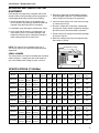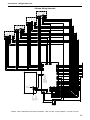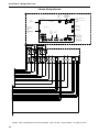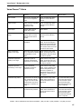
1
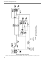
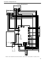
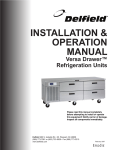
INSTALLATION &
OPERATION
MANUAL
Versa Drawer™
Refrigeration Units
Please read this manual completely
before attempting to install or operate
this equipment! Notify carrier of damage.
Inspect all components immediately.
Delfield 980 S. Isabella Rd., Mt. Pleasant, MI 48858
+1 (989) 773-7981 or (800) 733-8829 • Fax (866) 779-2040
www.delfield.com
July 2010
Versa Drawer™ Refrigeration Units
IMPORTANT WARNING AND SAFETY INFORMATION
Read this manual thoroughly before operating, installing, or performing maintenance
on the equipment.
FAILURE TO FOLLOW INSTRUCTIONS IN THIS MANUAL CAN CAUSE
PROPERTY
DAMAGE, INJURY OR DEATH.
DO NOT STORE OR USE GASOLINE OR OTHER FLAMMABLE VAPORS OR
LIQUIDS IN THE VICINITY OF THIS OR ANY OTHER APPLIANCE.
UNLESS ALL COVER AND ACCESS PANELS ARE IN PLACE AND PROPERLY
SECURED, DO NOT OPERATE THIS EQUIPMENT.
DAMP OR WET HANDS MAY STICK TO COLD SURFACES.
ALLOW HEATED EQUIPMENT TO COOL DOWN BEFORE ATTEMPTING TO
CLEAN
OR SERVICE.
DO NOT USE EXTENSION CORDS WITH THIS EQUIPMENT.
DO NOT USE ELECTRICAL APPLIANCES INSIDE THE FOOD STORAGE
COMPARTMENTS OF THE APPLIANCE.
DO NOT USE MECHANICAL DEVICES OR OTHER MEANS TO ACCELERATE THE
DEFROSTING PROCESS.
Observe the following:
•
•
•
•
Keep the equipment area free and clear of combustible material.
Maintain adequate clearance for air openings.
Operate equipment only on the type of electricity indicated on the specification
plate.
Models 18682VDR-CE, 18682VDL-CE and F18VD82-CE did not pass the flicker test
(IEC 61000-3-3). These models must not be connected to any electrical circuit with
lights.
Delfield · 980 S. Isabella Road, Mt. Pleasant, MI 48858 · (989) 773-7981 or (800) 733-8829 · Fax (989) 773-3210
Versa Drawer™ Refrigeration Units
Table of Contents
SAFETY PRECAUTIONS .......................................................................................... 2
RECEIVING AND INSPECTING THE EQUIPMENT ................................................. 4
SPECIFICATIONS .................................................................................................... 4
Serial Number....................................................................................................... 4
INSTALLATION
Location................................................................................................................ 5
Inside Cabinet....................................................................................................... 5
Outside Cabinet.................................................................................................... 5
Leveling................................................................................................................. 5
Stabilizing.............................................................................................................. 5
Plumbing............................................................................................................... 5
Electrical Connection............................................................................................ 5
Refrigeration System............................................................................................ 6
Temperature Monitoring........................................................................................ 6
Controller.............................................................................................................. 6
OPERATION
Operating Controls................................................................................................ 7
Setting the Drawer Mode................................................................................. 7
Setting Manual Defrost . ................................................................................. 7
MAINTENANCE
General Maintenance............................................................................ 8
Stainless Steel Care and Cleaning.................................................................. 8
Cleaning the Condenser Coil........................................................................... 8
PREVENTIVE MAINTENANCE
Gasket Maintenance............................................................................................ 9
Drawer Maintenance............................................................................................ 9
SCHEMATICS .....................................................................................................10-14
VERSA DRAWER ALARM....................................................................................... 15
STANDARD LABOR GUIDELINES TO REPAIR PARTS
ON DELFIELD EQUIPMENT . ........................................................................... 16
STANDARD ONE-YEAR WARRANTY . .................................................................. 17
SERVICE LABOR CONTRACT...........................................................................18-19
ADDITIONAL FOUR-YEAR PROTECTION PLAN ................................................. 20
Delfield · 980 S. Isabella Road, Mt. Pleasant, MI 48858 · (989) 773-7981 or (800) 733-8829 · Fax (989) 773-3210
Versa Drawer™ Refrigeration Units
RECEIVING AND INSPECTING THE
EQUIPMENT
Even though most equipment is shipped crated, care
should be taken during unloading so the equipment is
not damaged while being moved into the building.
4.Request an inspection by the shipping company
of the damaged equipment. This should be done
within 10 days from receipt of the equipment.
1.Visually inspect the exterior of the package and
skid or container. Any damage should be noted and
reported to the delivering carrier immediately.
5.Check the lower portion of the unit to be sure legs
or casters are not bent.
6.Be sure to inspect the compressor compartment
housing and visually inspect refrigeration package.
Be sure lines are secure and base is still intact.
2.If damaged, open and inspect contents with carrier.
3.In the event that the exterior is not damaged, yet
upon opening, there is concealed damage to the
equipment notify the carrier. Notification should be
made verbally as well as in written form.
7.Freight carriers can supply the necessary damage
forms upon request.
8.Retain all crating material until an inspection has
been made or waived.
NOTE: This manual covers standard units only. If
you have a custom unit, consult the technical service
department.
Serial Number Location
SERIAL NUMBER
The serial number is located on the data plate mounted
inside of Drawer 1. Always have the serial number of
your unit available when calling for parts or service.
SPECIFICATIONS (115V/60Hz)
Freestanding Models
Model
L
D
H
# of
Drawers
Volts
HZ
Amps
HP
Plug
Ref.
Charge
Ship Weight
lbs.
18650VDR
50"
127.0cm
31.5"
80.0cm
34"
86.4cm
2
115
60
6.0
1/3
5-15P
30oz.
520
18650VDL
50"
127.0cm
31.5"
80.0cm
34"
86.4cm
2
115
60
6.0
1/3
5-15P
30oz.
520
18682VDR
82"
208.3cm
31.5"
80.0cm
34"
86.4cm
4
115
60
12.0
(2) 1/3
5-15P
(2) 30oz.
720
18682VDL
82"
208.3cm
31.5"
80.0cm
34"
86.4cm
4
115
60
12.0
(2) 1/3
5-15P
(2) 30oz.
720
F2984VDR
84"
213.4cm
31.5"
80.0cm
26"
2
115
60
6.0
1/3
5-15P
30oz.
520
F2984VDL
84"
213.4cm
31.5"
80.0cm
26"
2
115
60
6.0
1/3
5-15P
30oz.
520
Component Crafted Models
Model
L
D
H
# of
Drawers
Volts
HZ
Amps
HP
Plug
Ref.
Charge
Ship Weight
lbs.
F18VD50
50"
127.0cm
31.5"
80.0cm
36"
91.4cm
2
115
60
6.0
1/3
5-15P
30oz.
520
F18VD82
82"
208.3cm
31.5"
80.0cm
36"
91.4cm
4
115
60
12.0
(2) 1/3
5-15P
(2) 30oz.
720
F17VD84
84"
213.4cm
31.5"
80.0cm
36"
91.4cm
2
115
60
6.0
1/3
5-15P
30oz.
620
Delfield · 980 S. Isabella Road, Mt. Pleasant, MI 48858 · (989) 773-7981 or (800) 733-8829 · Fax (989) 773-3210
Versa Drawer™ Refrigeration Units
SPECIFICATIONS (230-240V/50Hz)
Freestanding Models
Model
L
D
H
# of
Drawers
Volts
HZ
Amps
HP
Plug
Ref.
Charge
Ship
Weight
18650VDR-CE
50"
127.0cm
31.5"
80.0cm
34"
86.4cm
2
230-240
50
3.6
1/3
BS1373
850.5g
236kg
18650VDL-CE
50"
127.0cm
31.5"
80.0cm
34"
86.4cm
2
230-240
50
3.6
1/3
BS1373
850.5g
236kg
18682VDR-CE
82"
208.3cm
31.5"
80.0cm
34"
86.4cm
4
230-240
50
7.2
(2) 1/3
BS1373
(2) 850.5g
327kg
18682VDL-CE
82"
208.3cm
31.5"
80.0cm
34"
86.4cm
4
230-240
50
7.2
(2) 1/3
BS1373
(2) 850.5g
327kg
F2984VDR-CE
84"
213.4cm
31.5"
80.0cm
26"
66.0cm
2
230-240
50
3.6
1/3
BS1373
850.5g
236kg
F2984VDL-CE
84"
213.4cm
31.5"
80.0cm
26"
66.0cm
2
230-240
50
3.6
1/3
BS1373
850.5g
236kg
Component Crafted Models
Model
L
D
H
# of
Drawers
Volts
HZ
Amps
HP
Plug
Ref.
Charge
Ship Weight
F18VD50-CE
50"
127.0cm
31.5"
80.0cm
36"
91.4cm
2
230-240
50
3.6
1/3
BS1373
850.5g
236kg
F18VD82-CE
82"
208.3cm
31.5"
80.0cm
36"
91.4cm
4
230-240
50
7.2
(2) 1/3
BS1373
(2) 850.5g
327kg
F17VD84-CE
84"
213.4cm
31.5"
80.0cm
36"
91.4cm
2
230-240
50
3.6
1/3
BS1373
850.5g
236kg
The plug for the above models must be accessible at all times or a switch must be provided in the fixed
wiring in accordance with the wiring rules.
Delfield · 980 S. Isabella Road, Mt. Pleasant, MI 48858 · (989) 773-7981 or (800) 733-8829 · Fax (989) 773-3210
Versa Drawer™ Refrigeration Units
INSTALLATION
ELECTRICAL CONNECTION
Never stand on the unit or its drawers! Doing so may
result in bodily injury.
ELECTRICAL CONNECTIONS AND GROUNDING
CONNECTIONS MUST COMPLY WITH THE
APPLICABLE PORTIONS OF THE NATIONAL
ELECTRICAL CODE AND/OR OTHER LOCAL
ELECTRICAL CODES.
LOCATION
Units represented in this manual are intended for
indoor use only. Be sure the location chosen has
a floor strong enough to support the total weight of
the cabinet and contents, which can be up to 1,200
pounds(550kg). Reinforce the floor as necessary to
provide for maximum loading.
The location should be selected so that power cords
can be connected without any extension cords.
For the most efficient operation, be sure to provide
good air circulation inside and out. Avoid hot corners
and locations near stoves and ovens.
Direct exposure to excessive amounts of steam in
machine compartment will result in control board
failure.
INSIDE CABINET
Do not pack drawer so full that air cannot circulate.
Load product level with top of pans and keep all food
covered.
OUTSIDE CABINET
The front louvers must be kept 24"(60cm) clear of
any obstructions. Proper operation of these models is
dependent on air being able to flow freely through the
front louvers. Side louvers must have 24"(60cm) of
clearance for service access.
Any restriction of the proper airflow outlined above,
total or partial, will void the warranty on the unit.
LEVELING
The unit must be level so the drain pan will drain
properly, drawers will line up with frames and the
cabinet will not be subject to undue strain.
UNITS EQUIPPED WITH A FLEXIBLE ELECTRIC
SUPPLY CORD ARE PROVIDED WITH A
THREE-PRONG GROUNDING PLUG. THIS PLUG
MUST BE CONNECTED INTO A PROPERLY
GROUNDED THREE-PRONG RECEPTACLE. IF THE
RECEPTACLE IS NOT THE PROPER GROUNDING
TYPE, CONTACT AN ELECTRICIAN. DO NOT
REMOVE THE GROUNDING PRONG FROM THIS
PLUG.
A 7' (2.1 m) long grounded supply cord with threepronged plug is provided with the standard units.
Simply plug into a three-pronged wall outlet for proper
grounding of the unit to begin operation.
Refer to the amperage data listed in the specifications,
the serial number tag, your local code or the National
Electrical Code to be sure the unit is connected to the
proper power source. A protected circuit of the correct
voltage and amperage must be installed for connection
of the line cord or permanent connection to the unit.
Have the wall outlet checked by a qualified electrician
to be sure a proper ground is present and that the
outlet provides the correct voltage and required
amperage to match the specifications. Do not use an
adapter to connect to a two-pronged outlet. The threepronged-outlet provides a ground connection that must
be used to prevent a shock hazard.
Any power cord that is frayed or damaged should be
replaced. When disconnecting the unit from the power
source, do not pull on the cord. Firmly grip the plug
and remove from outlet.
STABILIZING
All models are supplied with legs or casters installed
for your convenience, for ease of cleaning underneath.
The unit must be installed in a stable condition.
The unit must be disconnected from the power
source whenever performing service, maintenance
functions or cleaning the refrigerated area.
PLUMBING
All models are standard with a condensate evaporator
pan.
Delfield · 980 S. Isabella Road, Mt. Pleasant, MI 48858 · (989) 773-7981 or (800) 733-8829 · Fax (989) 773-3210
Versa Drawer™ Refrigeration Units
OPERATION
Internet Info
GENERAL
The Versa Drawer unit has the capability to be
monitored remotely using the Internet. Using NAFEM
protocol to monitor HACCP information such as cabinet
and evaporator temperature as well as other key data
can be view live or past data can be pulled up.
Each drawer operates independently in one of four
modes at any time:
Refrigerator mode The drawer operates at a set
point of 37°F (3°C), maintaining a range between 34°F
(1°C) and 40°F (4°C).
Freezer mode The drawer operates at a set point of
-3°F (-19°C), maintaining a range between -6°F
(-21°C) and 0°F (-17°C).
Thaw Cabinet mode The drawer maintains
temperature between 36°F (2°C) and 41°F (5°C)
for a minimum of 4 hours or longer if required. Once
the thaw cycle is complete, the drawer mode is
automatically changed to refrigerator mode.
Convenience Chiller mode The drawer operates as
a chiller, maintaining the convenience chiller set point
of 23˚F (-5˚C) for four hours. Once the convenience
chiller cycle is complete, the drawer mode is changed
to refrigerator mode.
LAN line connection:
**Unplug unit before proceeding any further!
Note: A user provided Ethernet cable is
required
1. Disconnect power.
2.Remove access panel from end of machine
compartment.
3.Thread Ethernet cable through hole in back of unit
where power cable passes through. Connect to
Ethernet port located on back of display board.
Drawer gaskets are magnetic and mount to the drawer,
snapping in place and are removable without tools.
4.If necessary secure cable to prevent interference
with condenser fan blades.
REFRIGERATION SYSTEM
5.Connect other end of Ethernet cable to open port on
store router/switch.
In a 4-drawer system there are two compressors;
one operating drawers 1 and 2 and one operating
drawers 3 and 4. In a 2-drawer system there is a single
compressor.
TEMPERATURE MONITORING
Temperature sensors are located in each drawer. The
drawer temperatures are displayed on the control
panel.
CONTROL PANEL
The control panel provides information indicating the
current mode of each individual drawer. In addition,
the actual temperature of the drawer is displayed. See
page 7 for control panel operation
6.Attach access panel to end of unit.
7.Reconnect power to unit.
8.Contact Delfield service tech at 1-800-733-8829 with
the following information:
• Store Location
• Mac Address (To obtain the MAC address. First,
press the [!] button until “Program Menu” appears.
Press
button until brackets are around “SW
Version”. Write down “Gateway Mac Address ##
- ## - ## - ## - ## - ##” displayed on screen. Press
the
button twice to return to the main display
screen.
An automatic defrost occurs every six hours in
refrigerator and freezer mode.
• After this information is received the Delfield service
tech will inform you on Internet site access and a
password to view your data.
Chiller product Info
Wireless connection:
Please contact Delfield for help with wireless
connections.
DEFROST
Note: These results are based on chilling at a cabinet
temperature of 5˚F(-15˚C) and 10 pounds(4.5kg)
of product per drawer. The times are based on the
duration to go from 140˚F(60˚C) to 40˚F(4˚C). The
maximum limit of product to be chilled is no more than
10 pounds(4.5kg), not including pans. Product should
be covered and no more than 2"(5cm) deep in the pan.
Chill Time
Product
Mash Potatoes
3 hours 21 minutes
Scrambled Eggs
1 hour 53 minutes
Green Beans
2 hour 49 minutes
Soup (Vegatable)
2 hour 58
Spaghetti with Meat sauce
2 hours 32 minutes
Delfield · 980 S. Isabella Road, Mt. Pleasant, MI 48858 · (989) 773-7981 or (800) 733-8829 · Fax (989) 773-3210
Versa Drawer™ Refrigeration Units
OPERATION
OPERATING CONTROLS
All operating functions are accessible on the Versa
Drawer control panel. Operators can select the drawer
modes or activate the manual defrost. Access to
all diagnostic functions require a qualified service
technician.
2-Drawer Interface Control
1
2
3
4
Buttons are located next to the drawer display on
the Control Panel. The drawer select buttons select
the drawer to be configured.
These arrows are used to change a drawer to
operate in a desired mode (refrigerate, freezer,
thaw or chill).
Used to back up to the previous step.
The i button is used to initiate the manual
defrost mode.
4-Drawer Interface Control
MAINTENANCE
Setting the drawer mode
Select the drawer mode as follows:
1.Press the button next to the drawer display to be
changed.
NOTE: Current drawer mode text size will decrease.
2.Press the UP or DOWN arrow to select between
refrigerate, freeze, chill or thaw untill desired mode
is reached.
3.Press the drawer display button again to lock the
desired mode setting.
NOTE: Text size will return to original size.
Activating Manual Defrost
NOTE: The following two steps must be performed within 1 second.
Setting the Clock:
1.Press the [!] button until “Program Menu” appears.
2.Press the
button until brackets are around “Time
& Date”, then press
.
3.Press
adjusted.
button to get to parameter to be
Note: The [^] under the text show parameter to be adjusted.
4.Press the
buttons to adjust parameter.
5.Once correct time and date are set press the
button twice to return to the main display screen.
(If no action is taken for 30 seconds control
automatically returns to main display screen).
1.Press the desired drawer display button.
Fahrenheit to Celsius
2.Immediately press the
1.Press the [!] button until "Service Menu" appears.
button.
2.Press the
button until brackets are around
"Configuration", then press [!] .
3.Press
arrow to "System" and press [!] .
4.In this menu will be "Metric", change to Yes.
5.Press
arrow until back to main menu.
Delfield · 980 S. Isabella Road, Mt. Pleasant, MI 48858 · (989) 773-7981 or (800) 733-8829 · Fax (989) 773-3210
Versa Drawer™ Refrigeration Units
THE UNIT MUST BE DISCONNECTED FROM
THE POWER SOURCE WHENEVER PERFORMING
SERVICE, MAINTENANCE FUNCTIONS OR
CLEANING THE REFRIGERATED AREA.
GENERAL MAINTENANCE
Stainless Steel Care and Cleaning
To prevent discoloration or rust on stainless steel
several important steps need to be taken. First, the
properties of stainless steel need to be understood.
Stainless steel contains 70-80% iron that will rust. It
also contains 12-30% chromium that forms an invisible
passive film over the steel’s surface and acts as a
shield against corrosion. As long as the protective
layer is intact, the metal will not corrode, the metal is
still stainless. If the film is broken or contaminated,
outside elements can begin to break down the steel
and begin to form rust or other discoloration.
Never use steel pads, wire brushes or scrapers!
Do not use an abrasive cleaner because it will scratch
the stainless steel and plastic and can damage
the breaker strips and gaskets. Proper cleaning of
stainless steel requires soft cloths or plastic scouring
pads.
Cleaning solutions need to be alkaline based or nonchloride cleaners. Any cleaner containing chlorides
will damage the protective film of the stainless steel.
Chlorides are also commonly found in hard water, salts
and household and industrial cleaners. If cleaners
containing chlorides are used, be sure to rinse
repeatedly and dry thoroughly upon completion.
Cleaning the Condenser Coil
The condenser coil requires regular cleaning,
recommended is every 90 days. In some instances
you may find that there is a large amount of debris and
dust or grease accumulated prior to the 90-day time
frame. In these cases the condenser coil should be
cleaned as needed.
If the build up on the coil consists of only light dust and
debris the condenser coil can be cleaned with a simple
brush. Heavier dust build up may require a vacuum or
compressed air to blow through the condenser coil.
If heavy grease is present there are de-greasing
agents available for refrigeration use and specifically
for the condenser coils. The condenser coil may
require a spray with the de-greasing agent and then
blown through with compressed air.
Failure to maintain a clean condenser coil can initially
cause high temperatures and excessive run times.
Continuous operation with dirty or clogged condenser
coils can result in compressor failures. Neglecting
condenser coil cleaning procedures will void any
warranties associated with the compressor or cost to
replace the compressor.
Never use a high-pressure water wash for this
cleaning procedure as water can damage the
electrical components located near or at the
condenser coil.
If your freezer seems to vibrate excessively when the
compressor is running, loosen (but do not remove) the
bolts on the compressor. Semi hermetic models should
be loosened before operating.
Routine cleaning of the interior and exterior can be
done with soap and warm water. Extreme stains or
grease should be cleaned with a non-abrasive cleaner
and plastic scrub pad. When cleaning the exterior,
always rub with the grain of the stainless steel to
avoid marring the finish. There are also stainless steel
cleaners available which can restore and preserve the
finish of the steels protective layer.
Early signs of stainless steel breakdown can consist
of small pits and cracks. If this has begun, clean
thoroughly and start to apply stainless steel cleaners in
attempt to restore the passivity of the steel.
Never use an acid based cleaning solution! Many food
products have an acidic content that can deteriorate
the finish. Be sure to clean ALL food products from
any stainless steel surface. Common items include,
tomatoes, peppers and other vegetables.
Delfield · 980 S. Isabella Road, Mt. Pleasant, MI 48858 · (989) 773-7981 or (800) 733-8829 · Fax (989) 773-3210
Versa Drawer™ Refrigeration Units
PREVENTIVE MAINTENANCE
Reassembly
Gasket Maintenance
Push the drawer tracks into the drawer cage. The blue
safety clip must remain pushed towards the back.
Lift up and slide the drawer track all the way into the
drawer cage. The blue safety clip will lock in place
automatically. Once all tracks are replaced, insert the
drawer box. Rest the drawer box bottom track on the
front track roller. Then push the drawer back in place
SLOWLY. When the drawer box is about half way in
you will hit a STOP. You must lift the front of the drawer
up approximately ½” (1.3cm) to continue inward. Clean
tracks as often as possible. The cleaner the tracks are
the better they will operate.
Gaskets require regular cleaning to prevent mold and
mildew build up and also to keep the elasticity of the
gasket. Gasket cleaning can be done with the use of
warm soapy water. Avoid full strength cleaning products
on gaskets as this can cause them to become brittle
and prevent proper seals. Also, never use sharp tools
or knives to scrape or clean the gasket, which could
possibly tear the gasket and rip the bellows.
Gaskets can easily be replaced and do not require the
use of tools or authorized service persons. They can be
pulled out of the groove in the door and new gaskets
can be pressed back into place.
Drawer Maintenance
Drawer Assembly Cleaning
The drawer assembly is designed to be cleaned
easily. Both drawer and tracks are removable without
tools. The drawer tracks are dishwasher safe or can
be cleaned in a sink with detergents and a soft bristle
brush. Drawers and tracks should be cleaned on a
weekly basis.
Remove Drawers
Pull the drawer box out until it stops. Lift up on the
drawer front and pull the drawer box completely out.
Using a soft bristle brush, clean the track on the bottom
of the drawer box. When finished, it should be wiped
clean of all food and debris.
Tracks
The drawer box assembly must be removed. Pull the
drawer tracks out until they hit a stop. Locate blue
safety clips towards the back of each drawer track.
Blue safety clips have a tab on the top. Push the tab
back until it clicks. Lift up and pull the drawer tracks all
the way out of the
drawer cage. The
drawer tracks are
dishwasher safe or
can be cleaned in a
tab on top of
sink with detergents
blue safety clip
and a soft bristle
brush. Drawers and
tracks should be cleaned on a weekly basis. Using a
soft bristle brush, wash the track making sure each
roller is thoroughly cleaned. The drawer cage should
be cleaned with a soft bristle brush, removing any
food and debris gathered on the bottom ledge. Once
it’s cleaned thoroughly with a soft bristle brush, wipe
remaining debris clean with a soft towel.
Delfield · 980 S. Isabella Road, Mt. Pleasant, MI 48858 · (989) 773-7981 or (800) 733-8829 · Fax (989) 773-3210
NOTE: The four drawer unit has
two of these exact systems.
Versa Drawer™ Refrigeration Units
2-Drawer Refrigeration Schematic
Delfield · 980 S. Isabella Road, Mt. Pleasant, MI 48858 · (989) 773-7981 or (800) 733-8829 · Fax (989) 773-3210
10
.
'
,
#/--5.)#!4)/.#!",%
4/)/"/!2$
$)304/)/
4/
4/
4/
02%&%23()%,$%$47)34%$
0!)2!.$47)34%$
3()%,$
#/.42/,
0/7%2
"/8
*
*
*
#/.$
*
#/),
*
*
#/.$
"/8
*
#/),
$
*
#/),
$
"/8 #/),
"/8
*
"/8
*
#/),
$
*
*
#/),
$
*
"/8
*
*
*
*
0/7%24/
)/"/!2$
6
'2/5.$
$)304/)/
4/
4/
$)30,!9"/!2$
30
*
30
*
#/-0
*
!#(/4
*
#/-0
*
3%%"/!2$#/..%#4/2
&/20).#/..%#4)/.
$%4!),3
)/"/!2$
*
#/.$&!.
*
*
*
*
6!,6%3
$$
*
6!,6%3
*
*
*
$$
47/$2!7%27)2).'3#(%-!4)#
-42
-42
"/8
6$#
%6!0&!.3
%6!04%-0
02/"%
"/84%-0
02/"%
$2!7%2&2!-%
(%!4%2
$2!7%2,)-)4
37)4#(
-42
-42
"/8
"/84%-0
02/"%
%6!04%-0
02/"%
$2!7%2&2!-%
(%!4%2
$2!7%2,)-)4
37)4#(
6$#
%6!0&!.3
Versa Drawer™ Refrigeration Units
2-Drawer Wiring Schematic
Delfield · 980 S. Isabella Road, Mt. Pleasant, MI 48858 · (989) 773-7981 or (800) 733-8829 · Fax (989) 773-3210
11
12
#/--5.)#!4)/.#!",%
4/$)30,!9"/!2$
)/4/$)30
4/
4/
4/
02%&%23()%,$%$47)34%$
0!)2!.$47)34%$
3()%,$
6!#
(:
#/.42/,0/7%2
Delfield · 980 S. Isabella Road, Mt. Pleasant, MI 48858 · (989) 773-7981 or (800) 733-8829 · Fax (989) 773-3210
#/),
"/8
#/.$
*
"/8
*
"/8
*
$
$
#/),
*
#/.$
"/8
*
#/),
*
#/),
*
4%-0%2!452%3%.3/23
*
#/),
"/8
$
*
#/),
$
"/8
*
*
*
*
*
*
"/!2$#/..%#4/2-!0
30
*
30
*
35#4)/.
02%3352%
42!.3$5#%2
6
3)'.!,
#/--/.
)/"/!2$
#/-0
*
!#(/4
*
*!#(/4
&/2!,,!#
,/!$3
#/-0
*
*
*
#/.$&!.
*
0/7%24/
$)30,!9"/!2$
6
'2/5.$
)/4/$)30
4/
4/
*
$$6!,6%3
*
*
$$6!,6%3
*
6&/2$!.$$&!.3
$&!.32%452.
$&!.32%452.
6&/2$!.$$&!.3
$&!.32%452.
$&!.32%452.
*
*
",!#+#/-
7()4%6/54
2%$6$#).
#/.$/54
4%-002/"%
#/.$).
4%-002/"%
.3+
02%3352%
42!.3$5#%2
-42
#/-02%33/2
-42
#/.$&!.
2%&'
3/,%./)$
2%&'
3/,%./)$
(/4'!3
3/,%./)$
(/4'!3
3/,%./)$
*
$2%&'3/,%./)$
$(/4'!33/,%./)$
$2%&'3/,%./)$
$(/4'!33/,%./)$
*
$2%&'3/,%./)$
$(/4'!33/,%./)$
$2%&'3/,%./)$
$(/4'!33/,%./)$
$&2!-%(%!4%2
.#
$&2!-%(%!4%2
*
$&2!-%(%!4%2
.#
$&2!-%(%!4%2
#/--/.&/2$!.$$$2737)4#(%3
$37)4#(
$37)4#(
#/--/.&/2$!.$$$//237)4#(%3
$37)4#(
$37)4#(
$2!7%2/.%
$2!7%247/
Versa Drawer™ Refrigeration Units
2-Drawer Wiring Schematic
,
'
.
#/--5.)#!4)/.#!",%
4/)/"/!2$
$)304/)/
4/
4/
4/
02%&%23()%,$%$47)34%$
0!)2!.$47)34%$
3()%,$
#/.42/,
0/7%2
#/),
#/),
"/8
).
*
"/8
*
"/8
*
#/.$
/54
*
*
*
$
*
"/8
$
*
*
*
*
*
$
$
).
*
*
#/.$
/54
*
#/),
*
#/),
*
0/7%24/
)/"/!2$
6
'2/5.$
$)304/)/
4/
4/
$)30,!9"/!2$
30
*
30
*
#/-0
*
!#(/4
*
#/-0
*
3%%"/!2$#/..%#4/2
&/20).#/..%#4)/.
$%4!),3
)/"/!2$
*
*
#/.$&!.
*
*
$$6!,6%3
*
*
*
*
$$6!,6%3
*
-42
-42
"/8
6$#
%6!0&!.3
%6!04%-0
02/"%
"/84%-0
02/"%
$2!7%2&2!-%
(%!4%2
$2!7%2,)-)4
37)4#(
-42
-42
"/8
6$#
%6!0&!.3
%6!04%-0
02/"%
"/84%-0
02/"%
$2!7%2&2!-%
(%!4%2
$2!7%2,)-)4
37)4#(
-42
-42
"/8
6$#
%6!0&!.3
%6!04%-0
02/"%
"/84%-0
02/"%
$2!7%2&2!-%
(%!4%2
$2!7%2,)-)4
37)4#(
-42
-42
"/8
6$#
%6!0&!.3
%6!04%-0
02/"%
"/84%-0
02/"%
$2!7%2&2!-%
(%!4%2
$2!7%2,)-)4
37)4#(
Versa Drawer™ Refrigeration Units
4-Drawer Wiring Schematic
Delfield · 980 S. Isabella Road, Mt. Pleasant, MI 48858 · (989) 773-7981 or (800) 733-8829 · Fax (989) 773-3210
13
Versa Drawer™ Refrigeration Units
4-Drawer Wiring Schematic
"/!2$#/..%#4/2-!0
#/--/.&/2$!.$$$2737)4#(%3
$37)4#(
$37)4#(
#/--/.&/2$!.$$$//237)4#(%3
$37)4#(
$37)4#(
*
)/"/!2$
*
*
*
*
*
$&2!-%(%!4%2
.#
$&2!-%(%!4%2
*
4%-0%2!452%3%.3/23
*
*
*
"/8
*
#/),
*
"/8
#/),
$
*
*
#/),
"/8
*
"/8
*
#/),
*
*
#/-0
30
*
#/-0
*
*
*
#/.$&!.
!#(/4
*
$2%&'3/,%./)$
$(/4'!33/,%./)$
$2%&'3/,%./)$
$(/4'!33/,%./)$
$$6!,6%3
$$6!,6%3
.3+
02%3352%
42!.3$5#%2
&/2#/-0
",!#+#/-
7()4%6/54
-42
-42
2%$6$#).
",!#+#/-
7()4%6/54
2%$6$#).
#/-02%33/2
#/.$&!.
#/.$/54
4%-002/"%
#/.$).
4%-002/"%
.3+
02%3352%
42!.3$5#%2
&/2#/-0
-42
#/-02%33/2
#/.$&!.
-42
(/4'!3
3/,%./)$
(/4'!3
3/,%./)$
*
30
2%&'
3/,%./)$
$2!7%24(2%%
$2!7%2&/52
*
#/),
#/.$
2%&'
3/,%./)$
2%&'
3/,%./)$
2%&'
3/,%./)$
(/4'!3
3/,%./)$
*
*
"/8
#/.$
$2%&'3/,%./)$
$(/4'!33/,%./)$
$2%&'3/,%./)$
$(/4'!33/,%./)$
#/),
$
*
$2!7%2/.%
*
*
$
(/4'!3
3/,%./)$
*!#(/4
&/2!,,!#
,/!$3
$
*
"/8
$2!7%247/
$&2!-%(%!4%2
.#
$&2!-%(%!4%2
*
35#4)/.
02%3352%
42!.3$5#%2
6
3)'.!,
#/--/.
#/.$/54
4%-002/"%
#/--5.)#!4)/.#!",%
4/$)30,!9"/!2$
)/4/$)30
4/
4/
4/
02%&%23()%,$%$47)34%$
0!)2!.$47)34%$
3()%,$
#/.$).
4%-002/"%
6!#
(:
#/.42/,0/7%2
6&/2$!.$$&!.3
$&!.32%452.
$&!.32%452.
6&/2$!.$$&!.3
$&!.32%452.
$&!.32%452.
0/7%24/
$)30,!9"/!2$
6
'2/5.$
)/4/$)30
4/
4/
Delfield · 980 S. Isabella Road, Mt. Pleasant, MI 48858 · (989) 773-7981 or (800) 733-8829 · Fax (989) 773-3210
14
Versa Drawer™ Refrigeration Units
Versa Drawer™ Alarm
Alarm
Meaning
Action
Alternate Action
Thaw Finished
Thaw cycle is complete and
unit is now in refrigeration
mode.
Press corresponding drawer
number to clear audio and
screen.
Chiller Finished
Chiller cycle has completed
and unit is now in
refrigeration mode.
Press corresponding drawer
number to clear audio and
screen.
Drawer Open
Drawer's been open for
greater than set time.
Close drawer.
Drawer temperature Out of
Range.
Drawer temperature's been
10 deg F above or below
setpoint for more than 15
minutes.
Press corresponding drawer
number to clear audio and
screen.
Loss of power
Power to unit was
interrupted.
Press i button to stop audio
alarm. Screen will change to
display time power failed, time
power was restored. Present
time. Press i button once more
to return to main screen
Drawer temperature
probe(s) out of range.
Temperature probe to drawer
box or evaporator is damage
or temperature is out of
range.
Press i button to stop audio
alarm, screen will clear once
temperature drops into range
or probe is repaired.
Condenser temperature
probe(s) out of range.
Temperature probe to
condenser is damaged or
temperature is out of range.
Press i button to stop audio
alarm, screen will clear once
temperature drops into range
or probe is repaired.
Compressor pressure
transducer(s) out of range.
Pressure transducer
damaged or pressure is
higher than 150 psi
Press i button to stop audio
alarm. If unit is started in high
ambient temperature alarm
will clear on pulldown. If
diagnostics shows "open" for
transducer, component must
be repaired.
Condenser fan(s) failure
Condenser fan has fail to pull
down condenser outlet by
1 degree over two minutes.
Condenser fan may not be
operating or condenser coil
is dirty.
Press i button to stop audio
alarm. Alarm will remain on
screen until service work is
performed
The screen will clear if power
to the unit is disconnected
and reconnected. If alarm
keeps reoccurring after
power has been removed
service is required.
Compressor(s) Failure
Compressor has failed to
decrease suction pressure.
Press i button to stop audio
alarm. Alarm will remain on
screen until service work is
performed
The screen will clear if power
to the unit is disconnected
and reconnected. If alarm
keeps reoccurring after
power has been removed
service is required.
Delfield · 980 S. Isabella Road, Mt. Pleasant, MI 48858 · (989) 773-7981 or (800) 733-8829 · Fax (989) 773-3210
15
Versa Drawer™ Refrigeration Units
STANDARD LABOR GUIDELINES TO REPAIR OR REPLACE PARTS ON
DELFIELD EQUIPMENT UNDER WARRANTY
Advice and recommendations given by Delfield
Service Technicians do not constitute or guarantee any
special coverage.
A maximum of 1-hour is allowed to diagnose a
defective component.
A maximum of 1-hour is allowed for retrieval of parts
not in stock.
A maximum travel distance of 100 miles round trip and
2-hours will be reimbursed.
Overtime, installation/start-up, normal control
adjustments, general maintenance, glass breakage,
freight damage, and/or correcting and end-user
installation error will not be reimbursed under warranty
unless pre-approved with a Service Work Authorization
from Delfield. You must submit the number with the
service claim.
LABOR OF 1 HOUR IS ALLOWED TO REPLACE:
• Solenoid Coil
• Hi-limit/Thermal Protector Switch
• Compressor Start Components and Overload
Protector
• Evaporator/Condenser Fan Motor and Blade
• Door Hinges, Locks, and Gaskets
LABOR OF 2 HOURS TO REPLACE:
• Drawer Tracks/Cartridges
• Pressure Control
• Microprocessor Control
• Solenoid Valve
• Locate/Repair Leak
LABOR OF 3 HOURS TO REPLACE:
• Expansion Valve
• Condenser or Evaporator Coil
LABOR OF 4 HOURS TO REPLACE:
Compressor
This includes recovery of refrigerant and leak check.
Refrigerants
$55.00 (USD) maximum reimbursement for refrigerant
recovery (includes recovery machine, pump, torch,
oil, flux, minor fittings, solder, brazing rod, nitrogen, or
similar fees.)
R404A A maximum of $16.00/lb.(0.43kg) (USD).
Delfield · 980 S. Isabella Road, Mt. Pleasant, MI 48858 · (989) 773-7981 or (800) 733-8829 · Fax (989) 773-3210
16
Versa Drawer™ Refrigeration Units
STANDARD ONE YEAR WARRANTY (ONE YEAR PARTS AND LABOR.)
The Delfield Company (“Delfield”) warrants to the Original Purchaser of the Delfield product (herein called the “Unit”) that such Unit, and all
parts thereof, will be free from defects in material and workmanship under normal use and service for a period of one (1) year from the date of
shipment of the Unit to the Original Purchaser or, if the Original Purchaser returns the warranty card completely filled out including the date of
installation within thirty (30) days of receipt of the Unit, one (1) year from the date of installation. During this one year warranty period, Delfield
will repair or replace any defective part or portion there of returned to Delfield by the Original Purchaser which Delfield determines was defective due to faulty material or workmanship. The Original purchaser will pay all labor, crating, freight and related costs incurred in the removal
of the Unit of defective component and shipment to Delfield, except that during a period of either ninety (90) days from the date of shipment of
the Unit to the Original Purchaser or, if the Original Purchaser returns the warranty card completely filled out including the date of installation
within thirty (30) days of receipt of the Unit, ninety (90) days from the date of installation Delfield will pay all related labor costs. Delfield will pay
the return costs if the Unit or part thereof was defective.
The term “Original Purchaser” as used herein means that person, firm, association, or corporation for whom the Unit was originally installed.
This warranty does not apply to any Unit or part thereof that has been subjected to misuse, neglect, alteration, or accident, such as accidental
damage to the exterior finish, operated contrary to the recommendations specified by Delfield; or repaired or altered by anyone other than
Delfield in any way so as to, in Delfield’s sole judgement, affect its quality or efficiency. This warranty does not apply to any Unit that has been
moved from the location where it was originally installed. This warranty also does not cover the refrigerator drier or the light bulbs used in the
Unit. The warranty is subject to the user’s normal maintenance and care responsibility as set forth in the Service and Installation Manual, such
as cleaning the condenser coil, and is in lieu of all other obligations of Delfield. Delfield neither assumes, nor authorizes any other person to
assume for Delfield, any other liability in connection with Delfield’s products.
Removal or defacement of the original Serial Number or Model Number from any Unit shall be deemed to release Delfield from all obligations
hereunder or any other obligations, express or implied.
Parts furnished by suppliers to Delfield are guaranteed by Delfield only to the extent of the original manufacturer’s express warranty to Delfield.
Failure of the Original Purchaser to receive such manufacturer’s express warranty to Delfield. Failure of the Original Purchaser to receive
such manufacturers warranty shall in no way create any warranty, expressed or implied, or any other obligation or liability on Delfield’s part in
respect thereof.
IF THE CUSTOMER IS USING A PART THAT RESULTS IN A VOIDED WARRANTY AND A DELFIELD AUTHORIZED REPRESENTATIVE
TRAVELS TO THE INSTALLATION ADDRESS TO PERFORM WARRANTY SERVICE, THE SERVICE REPRESENTATIVE WILL ADVISE
CUSTOMER THE WARRANTY IS VOID. SUCH SERVICE CALLS WILL BE BILLED TO CUSTOMER AT THE AUTHORIZED SERVICE
CENTER’S THEN APPLICABLE TIME AND MATERIALS RATES. CONSIDER: CUSTOMER MAY INITIATE A SERVICE AGREEMENT
WITHOUT PARTS COVERAGE.
Under no condition does this warranty give the Original Purchaser the right to replace the defective Unit with a complete Unit of the same
manufacturer or of another make. Unless authorized by Delfield in writing, this warranty does not permit the replacement of any part, including
the motor-compressor, to be made with the part of another make or manufacturer.
If shipment of a replacement part is requested prior to the arrival in the Delfield factory of the part claimed to be defective, the Original
Purchaser must accept delivery of the replacement part of a C.O.D. basis, with credit being issued after the part has been received and
inspected at Delfield’s plant and determined by Delfield to be within this warranty.
No claims can be made under this warranty for spoilage of any products for any reason, including system failure.
The installation contractor shall be responsible for building access, entrance and field conditions to insure sufficient clearance to allow any
hood(s), vent(s), or Unit(s) if necessary, to be brought into the building. Delfield will not be responsible for structural changes or damages
incurred during installation of the Unit or any exhaust system.
Delfield shall not be liable in any manner for any default or delay in performance hereunder caused by or resulting from any contingency
beyond Delfield’s control, including, but not limited to, war, governmental restrictions or restraints, strike, lockouts, injunctions, fire, flood, acts
of nature, short or reduced supply of raw materials, or discontinuance of the parts by the original part manufacturer.
Except as provided in any Additional Four Year Protection Plan, if applicable, and the Service Labor Contract, if applicable, the foregoing is
exclusive and in lieu of all other warranties, whether written or oral, express or implied. This warranty supersedes and excludes any prior oral
or written representations or warranties. Delfield expressly disclaims any implied warranties of merchantability, fitness for a particular purpose
of compliance with any law, treaty, rule or regulation relating to the discharge of substances into the environment. The sole and exclusive
remedies of any person relating to the Unit, and the full liability of Delfield for any breach of this warranty, will be as provided in this warranty.
Other than this Delfield Standard One Year Limited Warranty, any applicable Delfield Additional Four Year Protection Plan or applicable Delfield
Service Labor Contract, the Original Purchaser agrees and acknowledges that no other warranties are offered or provided in connection with
or for the unit or any other part thereof.
In no event will Delfield be liable for special, incidental or consequential damages, or for damages in the nature of penalties.
IF DURING THE WARRANTY PERIOD, CUSTOMER USES A PART FOR THIS DELFIELD EQUIPMENT OTHER THAN AN UNMODIFIED
NEW OR RECYCLED PART PURCHASED DIRECTLY FROM DELFIELD OR ANY OF ITS AUTHORIZED SERVICE CENTERS AND/OR
THE PART BEING USED IS MODIFIED FROM ITS ORIGINAL CONFIGURATION, THIS WARRANTY WILL BE VOID. FURTHER, DELFIELD
AND ITS AFFILIATES WILL NOT BE LIABLE FOR ANY CLAIMS DAMAGES OR EXPENSES INCURRED BY THE CUSTOMER WHICH
ARISE DIRECTLY OR INDIRECTLY, IN WHOLE OR IN PART, DUE TO THE INSTALLATION OF ANY MODIFIED PART AND/OR PART
RECEIVED FROM AN UNAUTHORIZED SERVICE CENTER. If the warranty becomes void, Customer may purchase from Delfield, if available, a Service Agreement or service at the then current time and materials rate.
For more information on Delfield warranty’s log on and check out the service section of our web site at www.delfield.com.
Delfield · 980 S. Isabella Road, Mt. Pleasant, MI 48858 · (989) 773-7981 or (800) 733-8829 · Fax (989) 773-3210
17
Versa Drawer™ Refrigeration Units
The Delfield Company
SERVICE LABOR CONTRACT
he Delfield Company (“Delfield”) offers this service labor contract (the “Service Labor
T
Contract”), available at a nominal fee at the time of submission and acceptance of the
order for the above listed Delfield unit (the “Unit”), in accordance with the following terms
and conditions:
The Service Labor Contract is in addition to Delfield’s Standard One Year Limited
Warranty (the “One Year Warranty”) and Delfield Additional Four Year Protection Plan (the
“Four Year Warranty”). The terms and conditions of the One Year Warranty and the Four
Year Warranty are set forth in their entirety in those warranties.
The Service Labor Contract covers the cost of labor where, in Delfield’s sole judgment,
the Unit has proven to be defective in use and where recommended factory maintenance
has been performed. The Service Labor Contract does not cover costs of initial installation or start-up, normal control adjustments or maintenance, food or business loss.
The one year Service Labor Contract shall cover those costs incurred by the Original
Purchaser for a period of one (1) year from the date of shipment of the Unit to the Original
Purchaser and the two year Service Labor Contract shall cover those costs incurred by
the Original Purchaser for a period of two (2) years from date of shipment of the Unit to
the Original Purchaser.
The term “Original Purchaser” as used herein means that person, firm, association, or
corporation for whom the Unit was originally installed.
Any claims under this Service Labor Contract must be made in advance of the needed
repairs. Delfield will not pay for repairs not authorized in advance. Upon completion of
the repairs, an itemized statement must be submitted to Delfield’s Customer Service
Department at the address below and must contain the following information:
1) Dealer name, invoice number, model number and serial number of the Unit.
2) Date the Unit was shipped.
3) Date the Unit failed, together with the name and address of the service agency called
in to repair the Unit.
4) Full description of and circumstances surrounding the failure of the Unit.
5) Itemized bill of the repairs made to the Unit.
(continued)
Delfield · 980 S. Isabella Road, Mt. Pleasant, MI 48858 · (989) 773-7981 or (800) 733-8829 · Fax (989) 773-3210
18
Versa Drawer™ Refrigeration Units
The Delfield Company
(continued from previous page)
Upon review and approval of the claim by Delfield’s Customer Service Department, payment
will be made promptly only for the following costs:
1) Cost of service labor necessary to repair the Unit, provided that it is based on
straight time only and the duration is, in the sole judgment of Delfield, within reason
for the repair made.
2) Travel mileage of the service agency called upon to make the repair, provided
the distance is, in the sole judgment of Delfield, with a reasonable radius of the
installation site.
3) Cost of replacement parts, provided that permission to purchase locally was authorized by Delfield’s Customer Service Department in advance of the purchase.
Delfield shall not be liable in any manner for any default or delay in performance hereunder
caused by or resulting from any contingency beyond Delfield’s control, including, but not limited to, war, governmental restrictions or restraints, strikes, lockouts, injunctions, fire, floods,
acts of nature, short or reduced supply of raw materials, or discontinuance of the parts by the
original part manufacturer.
This Service Labor Contract is offered on all Delfield units, except remote refrigerators,
freezers and ventilation systems, installed in the United States and certain other preapproved locations in Canada and Mexico (the “Approved Locations”). It is not available on
cabinets supplied for remote installations nor on any units installed outside the Approved
Locations. This Service Labor Contract does not cover repairs to any Unit that has been
moved from the location where it was originally installed.
EXCEPT AS PROVIDED IN ANY APPLICABLE STANDARD ONE YEAR LIMITED WARRANTY
OR APPLICABLE ADDITIONAL FOR YEAR PROTECTION PLAN, THE FOREGOING IS
EXCLUSIVE AND IN LIEU OF ALL OTHER WARRANTIES, WHETHER WRITTEN OR
ORAL, EXPRESS OR IMPLIED. THIS SERVICE LABOR CONTRACT SUPERSEDES AND
EXCLUDES ANY PRIOR ORAL OR WRITTEN REPRESENTATIONS OR WARRANTIES.
DELFIELD EXPRESSLY DISCLAIMS ANY IMPLIED WARRANTIES OF MERCHANTABILITY,
FITNESS FOR A PARTICULAR PURPOSE OR COMPLIANCE WITH ANY LAW, TREATY,
RULE OR REGULATION RELATING TO DISCHARGE OF SUBSTANCES INTO THE
ENVIRONMENT. THE SOLE AND EXCLUSIVE REMEDIES OF ANY PERSON RELATING TO
THE UNIT, AND THE FULL LIABILITY OF DELFIELD FOR ANY BREACH OF THE SERVICE
LABOR CONTRACT, SHALL BE AS PROVIDED IN THIS SERVICE LABOR CONTRACT.
IN NO EVENT WILL DELFIELD BE LIABLE FOR SPECIAL, INCIDENTAL OR CONSEQUENTIAL
DAMAGES, OR FOR DAMAGES IN THE NATURE OF PENALTIES.
Delfield · 980 S. Isabella Road, Mt. Pleasant, MI 48858 · (989) 773-7981 or (800) 733-8829 · Fax (989) 773-3210
19
Versa Drawer™ Refrigeration Units
ADDITIONAL FOUR YEAR PROTECTION PLAN (for motor-compressor only)
Delfield Serial #
Model#
Installation
Date
In addition to the Standard One Year Warranty on the Motor-Compressor contained in the above listed Delfield product (the “Unit”), The Delfield Company (“Delfield”) also agrees to repair, or exchange with similar or interchangeable
parts in design and capacity at Delfield’s option, the defective Motor-Compressor contained in the Unit (the “MotorCompressor”), or any part thereof, for the Original Purchaser only, at any time during the four (4) years following the
initial one (1) year period commencing on the date of installation for the Original Purchaser. Failure of the Original
Purchaser to register the registration card containing the Original Purchasers name, address, date of installation,
model number and serial number of the Unit containing the Motor-Compressor within 30 days from the date of installation shall void this warranty. This additional warranty is only available if the Motor-Compressor is inoperative due
to defects in material or factory workmanship, as determined by Delfield in its sole judgement and discretion. The
Original Purchaser shall be responsible for returning the defective Motor-Compressor to Delfield prepaid, F.O.B. at
the address shown on the back cover of this manual.
The term “Original Purchaser” as used herein means that person, firm, association, or corporation for whom the
Unit was originally installed.
The term “Motor-Compressor” as used herein does not include unit base, air or water cooled condenser, receiver,
electrical accessories such as relay, capacitors, refrigerant controls, or condenser fan/motor assembly. This warranty does not cover labor charges incidental to the replacement of parts. This warranty further does not include
any equipment to which said condensing unit is connected, such as cooling coils, temperature controls or refrigerant metering devices. This warranty shall be void if the Motor-Compressor, in Delfield’s sole judgement, has been
subjected to misuse, neglect, alteration or accident, operated contrary to the recommendations specified by the Unit
manufacturer, repaired or altered by anyone other than Delfield in any way so as, in Delfield’s sole judgement, to
affect its quality or efficiency or if the serial number has been altered, defaced or removed. This Warranty does not
apply to a Motor-Compressor in any Unit that has been moved from the location where it was originally installed.
The addition of methyl chloride to the condensing unit or refrigeration system shall void this warranty.
General Conditions
Delfield shall not be liable in any manner for any default or delay in performance hereunder caused by or resulting from any contingency beyond Delfield’s control, including, but not limited to, war, governmental restrictions or
restraints, strike, lockouts, injunctions, fire, flood, acts of nature, short or reduced supply of raw materials, or discontinuance of any part or the Motor-Compressor by the unit manufacturer.
Replacement of a defective Motor-Compressor is limited to one (1) Motor-Compressor by us during the four (4) year
period. Delfield shall replace the Motor-Compressor at no charge.
This warranty does not give the Original Purchaser of the Motor-Compressor the right to purchase a complete
replacement Motor--Compressor of the same make or of another make. It further does not permit the replacement
to be made with a Motor-Compressor of another kind unless authorized by Delfield. In the event Delfield authorizes
the Original Purchaser to purchase a replacement Motor-Compressor locally, only the wholesale cost of the Motor-Compressor is refundable.
Expressly excluded from this warranty are damages resulting from spoilage of goods.
Except as provided in any applicable Standard One Year Limited Warranty or applicable Service Labor Contract, the
foregoing is exclusive and in lieu of all other warranties, whether written or oral, express or implied. This Warranty
supersedes and excludes any prior oral or written representations or warranties. Delfield expressly disclaims any
implied warranties of merchantability, fitness for a particular purpose or compliance with any law, treaty, rule or
regulation relating to the Motor--Compressor, and the full liability of Delfield for any breach of this warranty, will be
as provided in this warranty.
Other than any applicable Delfield Standard One year Limited Warranty, this Delfield Additional Four Year Protection
Plan and any applicable Delfield Service Labor Contract, the Original Purchaser agrees and acknowledges that no
other warranties are offered or provided in connection with or for the Motor-Compressor or any part thereof.
In no event will Delfield be liable for special, incidental or consequential damages, or for damages in the nature of
penalties.
Delfield · 980 S. Isabella Road, Mt. Pleasant, MI 48858 · (989) 773-7981 or (800) 733-8829 · Fax (989) 773-3210
20
Covington, TN
Mt. Pleasant, MI
Thank you for choosing Delfield!
Help is a phone call away. Help our team of professional, courteous
customer service reps by having your model number and serial number
available at the time of your call (800) 733-8829.
Model:_____________________ S/N: ____________________
Installation Date:_____________
For a list of Delfield’s authorized parts depots,
visit our website at www.delfield.com.
980 S. Isabella Rd., Mt. Pleasant, MI 48858, U.S.A. • (989) 773-7981 or (800) 733-8829 • Fax (989) 773-3210 • www.delfield.com
Delfield reserves the right to make changes in design or specifications without prior notice. ©2010 The Delfield Company. All rights reserved. Printed in the U.S.A.
DMVDOPS 07/10