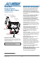
1
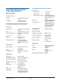
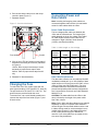
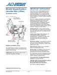
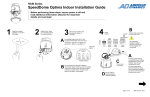
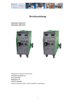
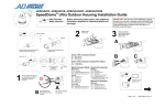
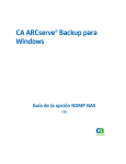
IMPORTANT SAFEGUARDS
SensorNet
Single-Position
Junction Box (J-Box)
The J-Box is a 10A, 2-pole, ganged disconnect
device, which also provides short circuit and
overload protection, and has a minimum 3mm
open circuit clearance, in accordance with the
National Electric Code and applicable local codes
must be installed at a location readily accessible to
the equipment.
Installation Guide
(Ein 10A, 2-poliges, gekoppeltes Ausschaltgerät,
welches auch über einen Kurzschluß- sowie
Überbelastungsschutz verfügt, und einen
minimum 3mm offenen Schaltabstand aufweist,
nach Übereinstimmung mit den Nationalen
Elektrischen Regelungen sowie lokalen Regeln,
muß an einem Standort installiert werden, welcher
einfachen Zugang zum Gerät erlaubt.)
Figure 1. SensorNet J-Box
Cover Retaining
Screws, Plastic (4)
On/Off Switch
Outside elements: To keep outside elements
from entering the J-Box, always mount it vertically
with cable exits facing down, and tighten the four
plastic screws.
Adding access holes to the enclosure: The
J-Box meets the NEMA 4 standard for
weatherproofing. To maintain this rating, make
sure any hole you drill in the enclosure is
thoroughly sealed with silicone-based RTV
compound.
Spare
Fuses (2)
Access for Cables
from Host and Dome
Switching to 240Vac: If using 240Vac to drive the
J-Box, you must change jumper terminations on
the primary winding of transformer. Refer to label
inside cover of J-Box.
Latches (2)
Approved power cords: Use only regulatoryapproved polarized power cords.
RJ1SNUD and RJ1SNUD-1 Series
Socket-outlet: For installation using a line cord,
the socket-outlet must be installed near the
equipment and at an easily accessible location.
This weather-tight box (Figure 1) provides Class 2
LPS power and data to the new SpeedDome Ultra
outdoor camera housing.
(Für Installationen mit einem Stromkabel muß die
Steckdose an einem Standort installiert werden,
welcher einfachen Zugang erlaubt.)
IMPORTANT: Read Regulatory Requirements
and other declarations on page 8.
This product does not support Manchester
protocol: It will support SensorNet.
USE ONLY WITH American Dynamics products
and other approved products from
Sensormatic Electronics Corporation.
See inside for additional safeguards.
© 2006 Sensormatic Electronics Corp.
SENSORNET SINGLE-POSITION JUNCTION BOX (J-BOX)
INSTALLATION GUIDE
8000-2573-21, REV. F
1 of 10
SensorNet Communication Interface
SensorNet Single-Position
J-Box Specifications
Cable distance:
J-Box to J-Box..................... 1km (3000ft)
REG ID: SV JBOX1
Host to J-Box ...................... 1km (3000ft)
J-Box to camera dome ........ Limited by the length of
the low-voltage ac power
cable. See Table 1 on
page 6.
Product Codes
RJ1SNUD .............................120V with North American
line cord
Cable type ................................ 1unshielded twisted pair,
22AWG, non-polarized
RJ1SNUD-1 ..........................230V with Continental
European line cord
Transformer primary jumpers and mains line cord are
field changeable to support either 120Vac or 230Vac
Surge protection....................... Isolation transformer
coupled, 2000 Vrms, gas
discharge tube impulse
rated at 10kA, 8/20µs,
TVS rated at 1W.
Electrical
Power source ........................100–120Vac or 200–240Vac,
50/60Hz
Connectors for host,
aux., and dome ........................ Pluggable Euro-style
Fuse......................................3.15A type IEC127, sheet III
Environmental
Max. operational limits ..........90–135Vac or 180–265Vac,
50/60Hz
Weatherproof standard ............ NEMA 4 / IP66
Input current..........................1.0A/.5A
Operating temperature ............. –40°C to 50°C
(–40°F to 122°F)
Output ...................................26Vac, 2.4A max.
Class 2 LPS
Storage temperature ................ –10°C to 50°C
(14°F to 122°F)
Power line protection ............Gas Discharge tube
impulse rated at 8/20µs
impulse discharge current:
10kA
Relative humidity...................... 0 to 95%
non-condensing
Regulatory
Operational
EMC ......................................... 47 CFR, Part 15, Class A
EN55022, Class B
Diagnostic LEDs ...................Host, aux., dome activity,
noise, power
Immunity................................... EN50082-1
Safety....................................... UL1950
CSA 22.2, No. 950
EN60950
Power....................................On/Off switch
Compatible with ....................SpeedDome Ultra outdoor
housing
See additional declarations on last page.
Mechanical
Environment..........................Indoor / Outdoor
Wall mounting options...........concrete, wood, sheet rock
Dimensions (H x W x D)........200 x 200 x 132mm
(7.87 x 7.87 x 5.19 in.)
Mounting area (H x W)..........281 x 200mm (11 x 8 in.)
Weight:..................................3.7 kg (8.25 lbs)
Construction..........................Polycarbonate, nonmetallic enclosure
Color .....................................Light gray
Cover locks ...........................2 quick-release latches
Cable access ........................3 ½-inch NPT strain relief
fittings provided for power,
host, and dome cables.
SENSORNET SINGLE-POSITION JUNCTION BOX (J-BOX)
INSTALLATION GUIDE
8000-2573-21, REV. F
2 of 10
Mounting the J-Box
Figure 2. Wall-mounting the J-Box
This section explains how to mount the J-Box to a
wall or pole.
200mm (7.9")
Parts Required
114.3mm (4.5")
Installation Kit (0351-1646-01) includes:
Screw, Self-tapping, 4.8x25, PHP
Anchor Bolt, ¼-20x2¼, w/Hardware
Anchor, Toggle, Nylon, #8-#10 Screw
4
4
4
5810-5081-111
2880-0011
2880-0073-01
76.2mm (3.0")
152.4mm
(6.0")
CAUTION: Before you begin, do the following:
− Mount the box near an accessible ac outlet.
255mm (10")
− Always use dedicated, unswitched, and
properly grounded 24-hour ac power. Power
should be supplied in accordance with local
codes.
− Mount the J-Box so its power on/off switch is
readily accessible and its strain relief fittings
are face down.
Indoor Wall Mounting
Mount the J-Box to the wall as follows (Figure 2):
1. Using the upper and lower mounting brackets
of the box as templates, mark mounting hole
locations. The two center top slots in the upper
bracket match the bolt spacing used for older
J-Boxes.
CAUTION: J-Box meets NEMA 4 standard for
weatherproofing. To maintain this rating,
ensure holes drilled in the enclosure are
thoroughly sealed with silicone-based RTV
compound. All outdoor wiring must be through
conduit, and tighten the four plastic screws.
2. Install the J-Box to drywall, concrete, or wood
(see note below).
• Drywall: Use four self-tapping screws and
Nylon anchors provided.
• Concrete: Use four anchor bolts provided.
Use a 6.3mm (1/4in) masonry bit (not
provided) to drill screw holes.
• Wood: Use four self-tapping screws.
Note: To facilitate installation, use the two open
slots in the lower mounting bracket to rest the
box on the screws while inserting screws
through the upper bracket.
3. Tighten mounting hardware to secure the
J-Box.
SENSORNET SINGLE-POSITION JUNCTION BOX (J-BOX)
INSTALLATION GUIDE
8000-2573-21, REV. F
3 of 10
b. Using your fingers, flatten the last 2.54cm
(1in) of band inward to form a hook. Insert
hook through remaining slot in rack and turn
screw to secure J-Box to pole (Figure 4e).
Outdoor Pole Mounting
Outdoor mounting (Figure 3) requires that PC
board, chassis, and power cord be removed to
facilitate attachment to pole. PC board and
chassis are reattached once box is secured.
5. Run cables and attach wires. See “Connecting
AC Power” and “Connecting Power and Data
Cables”. Caution: Do not use power cord
supplied with box for outdoor installations.
Note: Pole Mount Kit RHOPM, supplied with the
pole mount structure, includes straps sufficient for
10–30.5cm (4–12in) wide poles. For larger widths,
order an additional kit.
Figure 4. Pole-mount—details
Figure 3. Outdoor pole mount
a.
Straps P/N:
6010-0043-01
Remove PC
board assembly.
Remove chassis
assembly.
Rear of J-Box
Discard
power cord.
1. On the ground:
a. Remove PC board assembly and chassis
assembly from box (Figure 4a).
b. Remove power cord and attach conduit to
box. Ensure connections are liquid-tight.
c. Remove racks, screw assemblies, and band
from clamp package. Carefully uncoil band
and cut it in half to form two bands.
d. With words “this side up” etched in rack
facing up, insert rack into screw assembly
(Figure 4b). Then turn screw just enough to
engage rack. Prepare two racks this way.
b.
c.
Band 2
Rear of Box
2. As shown in Figure 4c, with J-Box on ground
and its rear facing towards you:
a. Slip one of the two bands through closed
slots in lower mounting bracket. Pick slots
appropriate for the width of the pole.
b. Bend end of left side of band inward.
c. Slip bent end through large slot in screw
assembly and flatten tight with fingers.
d. Repeat for upper mounting bracket.
Band 1
d.
Cut
e.
3. Place box in its mounting location against pole.
Then wrap both band assemblies around pole
so screws are opposite J-Box.
4. Holding J-Box in place, perform the following
for each band:
a. Cut band to length at a point 2.54cm (1in)
beyond first notch in band (Figure 4d).
SENSORNET SINGLE-POSITION JUNCTION BOX (J-BOX)
INSTALLATION GUIDE
8000-2573-21, REV. F
4 of 10
3. Disconnect ac power cord from TB1 (Figure 6).
Connecting AC Power
4. Loosen four screws to detach chassis.
The J-Box comes wired for 120Vac and has a 2m
(6ft 7in) SJT 3-conductor power cord attached.
Plug the cord into a dedicated 24-hour,
unswitched outlet.
5. Detach strain relief securing cord and remove
cord (refer to Figure 12).
Figure 6. Transformer compartment detail
If the box is to be driven by 240Vac, then the
power cord (if used) and jumpers across the
primary winding of the transformer within the box
will have to be changed (Figure 6).
Chassis
Screws (4)
CAUTION: Use only regulatory-approved
polarized power cords.
Hardwiring the J-Box
TB1
If the box is to be hardwired to the ac source, then
the chassis within the box and the power cord will
have to be removed to facilitate connection. Refer
to Figures 5, 6, and 13 for how to remove these
parts.
CAUTION: Keep the disconnect device (circuit
breaker) readily accessible when hardwiring
J-Box.
Do the following:
24V
1. Unplug line cord from ac outlet.
12V
Power On/Off
Switch
Transformer
1
2
0V
Red
TB1
L1
N / L2
Blk
120V
GND
2. Loosen two screws, then slide and lift PC
board assembly to remove and access ac
connections (Figure 5).
0V
3
GND
4
0V
120V
Red
Transformer Primary
Jumper Settings
120Vac 1-3, 2-4
Figure 5. Accessing connections
240Vac 2-3
Loosen screws, then
slide and lift PC board
assembly to remove.
SENSORNET SINGLE-POSITION JUNCTION BOX (J-BOX)
INSTALLATION GUIDE
Blk
Chassis Connections
AC Line Connections
Color
Pin
Function
Pin
Function
Green/
Yellow
E1
Ground
E1
Ground
Black
2
Neutral (N / L2)
2
Neutral (N / L2)
Black
3
Line (L1)
3
Line (L1)
8000-2573-21, REV. F
5 of 10
6. Run conduit and ac cable to box and clamp
conduit in place (Figure 7).
Connecting Power and
Data Cables
7. Reattach chassis.
Note: Incoming and outgoing video cables are
connected together within the box. No termination
exists for video cables within the J-Box.
Figure 7. Conduit attachment
Power Cable Requirements
The low-voltage power cable runs between the
J-Box and the camera dome. The length of this
cable depends on the ac line voltage. See Table 1
for cable lengths based on worst case low line
voltages for Japan (100Vac), North America
(120vac), and Europe (240vac).
Table 1. Cable length vs. line voltage
Fuse holders
Worst
Case Line
Voltages
Conduit
8. Wire ac line to TB1 and jumper primary taps of
transformer according to ac source (refer back
to Figure 6).
120Vac: Place a jumper across taps 1 and 3,
and another jumper across taps 2 and 4.
240Vac: Place a jumper across taps 2 and 3
only.
18AWG
16AWG
14AWG
90 Vac
(Japan)
30m
(100ft)
50m
(160ft)
80m
(260ft)
102 Vac
(N. Amer.)
60m
(200ft)
100m
(320ft)
160m
(520ft)
180 Vac
(Europe)
30m
(100ft)
50m
(160ft)
80m
(260ft)
204 Vac
(Europe)
60m
(200ft)
100m
(320ft)
160m
(520ft)
Data Cable Requirements
9. Reattach PC board assembly.
To reduce the risk of fire, replace fuses with the
same type and rating (3:15A type IEC127, sheet III).
The part number for the fuse is 5111-0017-21. Two
spare fuses are provided inside the cover.
The data cable contains one non-polarized 22AWG,
unshielded, twisted pair. Up to 1km (3000ft) of data
cable can be run from the Host to the J-Box, or from
J-Box to J-Box (see CAUTION below). For more
information about the SensorNet communication
protocol and possible cable network configurations,
see Communication Protocols and Cable Networks,
8000-2573-19.
To access fuse, use a small slotted screwdriver to
unscrew the cap of the fuse holder (Figure 7) and
lift out the fuse.
CAUTION: The data cable from the J-Box to the
dome is limited by the length of the power cable.
See Table 1 above.
Changing the Fuse
Note: Power, data, and video cables can be ordered
separately or within a composite cable ordered in
various lengths. Plenum-rated cables must be used
in indoor ceilings used for environmental air return
(called “other air space” in the National Electrical
Code). Order parts through your distribution
network. If you order cable from an outside source,
wire colors may be different.
SENSORNET SINGLE-POSITION JUNCTION BOX (J-BOX)
INSTALLATION GUIDE
8000-2573-21, REV. F
6 of 10
Referring to Figure 8:
P1
AUX
JW4
JW1
1
1-2 Terminated*
2-3 Unterminated
(*Default setting)
JW2
BRN
BLK
RED
WHT
YEL
HOST
SNet –
AC –
Gnd –
AC –
SNet –
SensorNet PCB
1
2. Route power and data cables through strain
relief fittings in bottom of box.
1
1
1. Turn power switch in J-Box to off (0). Power
LED should be off.
DOME 123
Figure 8. PCB connectors and jumpers
Procedure
P7
3. Connect power and data cables to 5-pin
compression connector (supplied on board).
Color code shown is for composite cable.
Power and Data
Description
1
2
3
4
5
YEL
WHT
RED
BLK
BRN
SensorNet
AC
Ground
AC
SensorNet
1
Host and
Aux Data
AUX
HOST
456
123
FALSE CD
5-Pin Compression Connector
Wire Color
Aux
Aux
Host
Host
1
AC PWR
+5Vdc
Pin
P8
Testing for Power and Data
LEDs on the circuit board (Figure 8) verify that
power and data are entering the J-Box.
4. Plug 5-pin connector into receptacle P1.
LED
Indication
5. Connect auxiliary and host data cables to 4-pin
compression connector P8 (supplied on board).
Color code shown is for composite cable.
AC PWR
Glows yellow to indicate 24 volt
AC power from transformer.
+5Vdc
Glows green to indicate DC
power from on-board regulator.
False CD
Glows red for 1/2 sec. to indicate
spurious false carrier detects.*
Carrier
Detect 123
Glows yellow to indicate
communications from connector
P1 to dome.*
4-Pin Compression Connector
Pin
Wire Color
Description
1
2
3
4
YEL
BRN
YEL
BRN
Host
Host
Aux.
Aux.
(Carrier Detect 456 is not used.)
6. Plug 4-pin connector into receptacle P8.
7. Place jumper JW1 (Dome) across pins 1–2 to
terminate J-Box (default setting) when the
J-Box is to be the end point of a data line.
Place JW1 across pins 2-3 (unterminated) if
the J-Box is to be the hub of a star network.
*
For jumpers JW2 and JW3: See Communications
Protocols and Cable Networks, 8000-2573-19.
SENSORNET SINGLE-POSITION JUNCTION BOX (J-BOX)
INSTALLATION GUIDE
Carrier
Detect Aux.
Glows yellow to indicate
communications from auxiliary
device.*
Carrier
Detect Host
Glows yellow to indicate
communications from Host.*
Retriggerable indicators remain on if triggered faster
than the remaining time.
8000-2573-21, REV. F
7 of 10
Troubleshooting
Removing the Transformer
Problem
Possible Solution
No Power
First check both fuses, then
look for open or loose wire
connections at TB1. If loose,
reconnect wires.
Measure voltage across 0
and 24V taps of secondary
winding on transformer. If
open, replace transformer.
See “Removing the
Transformer” opposite.
Follow steps to remove the transformer. Reverse
steps to reassemble.
No Data
1. Loosen four captive screws to release cover.
2. As shown in Figure 10, loosen two screws shown
in and slide chassis in direction of arrows. Gently
lay chassis on inside front cover while working on
transformer. Slide PCB chassis out of box.
Figure 10.
Check for loose wires. If OK,
see “Testing for Power and
Data” on page 7.
Removing the Circuit Board
Follow steps to remove the circuit board. Reverse
steps to reassemble.
Screws (2)
1. Loosen four captive screws to release cover.
2. Remove six screws to remove circuit board
(Figure 9).
3. Remove four nuts to remove transformer
(Figure 11).
Figure 9.
Figure 11.
Screws (6)
Screws
(6)
SENSORNET SINGLE-POSITION JUNCTION BOX (J-BOX)
INSTALLATION GUIDE
Nuts (4)
8000-2573-21, REV. F
8 of 10
Ordering Parts
Only the following parts can be ordered:
•
•
•
•
•
•
SensorNet PC Board 0312-0512-02
5-Pin Connector 2109-0254-04
4-Pin Connector 2109-0254-03
Power Transformer 5604-0205-01
Cable Strain Relief 3100-0035-11
Fuse 5111-0017-21.
These parts are shown bold in Figure 12.
Circuit Board, 0312-0512-02
5-Pin Connector, 2109-0254-04
Figure 12. Exploded view of SensorNet J-Box
4-Pin Connector, 2109-0254-03
Circuit
Board
Assy.
On/Off
Switch
Labels
Chassis
Fuses, 5111-0017-21
Transformer, 5604-0205-01
Strain Relief (3), 3100-0035-11
SENSORNET SINGLE-POSITION JUNCTION BOX (J-BOX)
INSTALLATION GUIDE
8000-2573-21, REV. F
9 of 10
Declarations
This product can only be used with American Dynamics
products and other approved products from Sensormatic
Electronics Corporation.
When the unit is hard wired, the disconnect device (circuit
breaker) must be readily accessible.
To meet regulatory approvals, only use approved polarized
plug/cordsets. Install the AC outlet near the equipment where
it is easily accessible.
FCC COMPLIANCE: This equipment has been tested and
found to comply with the limits for a Class A digital device,
pursuant to Part 15 of the FCC Rules. These limits are
designed to provide reasonable protection against harmful
interference when the equipment is operated in a commercial
environment. This equipment generates, uses, and can radiate
radio frequency energy and, if not installed and used in
accordance with the instruction manual, may cause harmful
interference to radio communications. Operation of this
equipment in a residential area is likely to cause harmful
interference in which case the user will be required to correct
the interference at his own expense.
EQUIPMENT MODIFICATION CAUTION: Equipment
changes or modifications not expressly approved by
Sensormatic Electronics Corporation, the party responsible
for FCC compliance, could void the user's authority to
operate the equipment and could create a hazardous
condition.
WARRANTY DISCLAIMER: Sensormatic Electronics
Corporation makes no representation or warranty with respect
to the contents hereof and specifically disclaims any implied
warranties of merchantability or fitness for any particular
purpose. Further, Sensormatic Electronics Corporation
reserves the right to revise this publication and make changes
from time to time in the content hereof without obligation of
Sensormatic Electronics Corporation to notify any person of
such revision or changes.
LIMITED RIGHTS NOTICE: For units of the Department
of Defense, all documentation and manuals were developed at
private expense and no part of it was developed using
Government Funds. The restrictions governing the use and
disclosure of technical data marked with this legend are set
forth in the definition of "limited rights" in paragraph (a) (15)
of the clause of DFARS 252.227.7013. Unpublished - rights
reserved under the Copyright Laws of the United States.
COPYRIGHT NOTICE: SpeedDome and American
Dynamics are registered trademarks of Sensormatic
Electronics Corporation. Other product names (if any)
mentioned herein may be trademarks or registered trademarks
of Sensormatic or other companies.
No part of this guide may be reproduced in any form without
written permission from Sensormatic Electronics Corporation.
RLJ/CSD 04/2006
www.americandynamics.net
SENSORNET SINGLE-POSITION JUNCTION BOX (J-BOX)
INSTALLATION GUIDE
8000-2573-21, REV. F
10 of 10