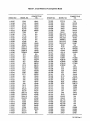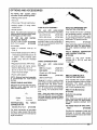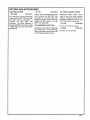
1
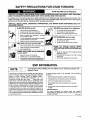
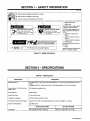
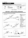
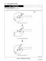
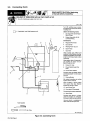
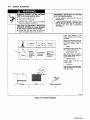
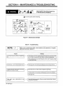
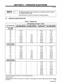
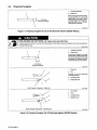
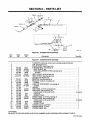
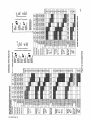
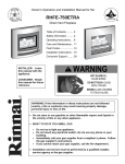
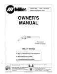
Millerfi
December 1993
Effective With
Form:
Style
OM-1568B
No. KB-8
OWNERS
MANUAL
MTL-20 Torches
Water-Cooled Torches For GTAW
Rated At 250
Amperes
.020 Thru 5/32 in
(0.5
100%
Duty Cycle Using Argon Shielding Gas
Thru 4.0
Includes 12-1/2 Or 25 ft
Welding
mm) Tungsten Size Capacity
(3.8 Or
7.6
m) Cable
Remote Contactor And Current Control Available
Tungsten Electrode And Some
Torch Parts Needed
Read and follow these instructions and all
blocks carefully.
U
Give this manual to the operator.
safety
Have
only
trained
install, operate,
or
and qualified persons
service this unit.
For
Call your distributor if you do not understand
the directions.
cover
7/93
ST-141 476-A
'
1993 MILLER Electric
or:
help, call your
distributor
MILLER Electric Mfg. Co., P.O. Box 1079,
414-734-9821
WI 54912
Appleton,
MIg. Co.
PRINTED IN USA
1F
TRUE BLU ETTM LIMITED WARRANTY
MILLERS
Effective
(Equipment
with
a
January
serial number
This limited warranty sapersedes all previous MILLER warranties and
Subject
LIMITED WARRANTY
Co
MIg
.
to
Appleton. Wisconsin,
is
1, 1992
preface of KC
exclusive with
the terms and conditions below, MILLER Electric
warrants
to
its
original
retail
purchaser
that
no
newer)
or
other gaarantees or warranties expressed or
implied.
Remote Controls
new
*
Accessory Kits
MILLER equipment sold alter the effective date 01 this limited warranty is tree ot de
tects in material and workmanship at the time it is skipped by MILLER THIS WAR.
Replacement Pans
RANTY IS EXPRESSLY IN LIEU OP ALL OTHER WARRANTIES, EXPRESS OR
MILLER S Trae Efae
IMPLIED, INCLUDING THE WARRANTIES OF MERCHANTAPILITY AND FIT
Limited Watranty shall net
apply
to.
NESS
I
Within the warranty periods listed below
MILLER will reoair
ranted parts or components that tail dye to sack detects
MILLER mast be notitied
in
or
material
replace any
or
writing within thirty 1301 days 01 sack defect
in
which time MILLER will provide instructions
on
the
Items tarnished
trade
war
or
tailare.
warranty claim procedures
to
one
year user the equipment
was
delivered to the
original
retail parchaser.
3 Years
2
or
In the event of
Plasma Arc
shall be. at MILLER S option
*
Semi-Automatic and Automatic Wire Feeders
Catting
Power Sources
Driven
a
Air
Compressors
period 01
two
vice
the engine manufacturer
Systems
warranty claim covered by this warranty, the exclusixe remedies
(11 repair. or (2( replacement, or, where authorized in
in appropriate cases. (3) the reasonable cost of repairer replace
us
determined by MILLER. Therefore no compensation
costs of any kind will be allowed,
or
reimburse
trunsportatiee
ANY EXPRESS WARRANTY
BASED ON
CON
NOT PROVIDED HEREIN ANO ANY IMPLIED WAR
RANTY GUARANTY OR REPRESENTATION AS TO PERFORMANCE AND ANY
REMEDY FOR BREACH OF CONTRACT TORT OR ANY OTHER LEGAL
THEORY WHICH. BUT FOR THIS PROVISION. MIGHT ARISE BY IMPLICATION.
OPERATION OF LAW, CUSTOM OF TRADE OR COURSE OP DEALING. IN
CLUDING ANY IMPLIED WARRANTY OF MERCHANTABILITY OR PITNESS
Spot Welders
Load Banks
SOX Transformers
FOR PARTICULAR PURPOSE, WITH RESPECT TO ANY AND ALL EQUIPMENT
FURNISHED BY MILLER IS EXCLUDED AND DISCLAIMED BY MILLER
Running Gearrrrailers
Field Options
(NOTE Field options
are
covered ander Trae
warranty period of the predact they
whichever is greater I
one year
are
BluenM
installed
in,
or
Some states
far the remaining
for a minimam of
in
the U S A
do not allow limitations 01 how long
lasts, or the exclusion of incidental, indirect,
special
or
an implied warranty
consequential damages, so
the above limitation or exclusion may not apply 10 you This warranty pronides spe
citic legal rights, and sther rights may be aeuilable, but may eury trem state to state.
-
Batreries
In Canada.
Days
a
LIABLE FOR DIRECT INDIRECT, SPECIAL. INCIDENTAL OR CONSEQUENTIAL
Grids
90
equipment
DAMAGES
INCLUDING LOSS OF PROFIT), WHETHER
TRACT TORT OR ANY OTHER LEGAL THEORY
HP Units
6 Months
br the
TO THE EXTENT PERMITTED BY LAW. THE REMEDIES PROVIDED HEREIN
ARE THE SOLE AND EXCLUSIVE REMEDIES IN NO EVENT SHALL MILLER BE
Parts and Labor
Water Coolant
facility
ment for
Process Controllers
*
centacters
years.(
Motor Driven Guns
*
tips. catting nozzles,
wear
ment at an authorized MILLER sernrce station. or (4) payment of or credit br the pur
chase price (less reasonable deprecrutrOn based upon actual ase( apes return eb the
goods at customers risk and espense. MILLERS option 01 repair or replacement
will be P0 B Factory at Appleton, Wisconsin, or F 0 B at a MILLgR authorized ser
Welding Generators
are warranted separately by
for
Year
1
it
writing by MtLLER
Parts and Labor
(NOTE Engines
B,
specifications
*
*
er
MILLER PRODUCTS ARE INTENDED FOR PURCHASE AND USE BY COMMER
CIALINDUSTRIAL USERS AND PERSONS TRAINED AND EXPERIENCED IN
THE USE AND MAINTENANCE OP WELDING EQUIPMENT.
main power rectiliers
Parts and Labor
Engine
as contact
parts that tail dye to normal
Transformer/Rectifier Power Searces
2 Years
engines
warranty,
based apon indastry standards. or eqaipment which has net had reasonable
and necessary maintenance. or equipment whick has been axed tsr operation
Robots
3
as
3 Yeats Labor
-
Original
sack
ment
or
sent to the distributor
is
relays
outside of the
5 Years Parts
by others.
by the manafecturers
Equipment that has been modrfied by any party ether than MILLER. or equip
that has been improperly installed, improperly operated or misased
3
MILLER shall honor warranty claims en warranted equipment listed below in the
All warranty time periods
a dilute within the warranty time periods
eeent 01 sack
the date that the equipment
covered
are
Consumable components, sack
2
and
on
MILLER. bat manafactared
These items
at
be
toltawed
start
by
accessories
any
workmanship.
or
Parts and Labor
legislation
proxinces proeides or certain additional warranties
staled herein, and to the extent that they may not be
in some
remedies other than
as
MIG Gsns/TIG Torches
waived, the limitations and exclusions set out aboxe may net apply. This Limited
Warranty pieuides specific legal rights. and other rights may be uxailuble. but map
Plasma
vary Irom province to proxince.
Catting
Torches
IF
:JU
RECEIVING-HANDLING
Before
loss
with the
unpacking equipment, check carton for any damage that may have occurred duhng shipment. File any claims for
delivering carrier. Asststance for filing or settling claims may be obtained from distributor and/or equipment
Transportation Department.
manufacturers
When
requesting
Use the
or
following
information about this
equipment, always provide Model Designation and Serial
spaces to record Model
Designation
and Serial
or
Style
or
Style
or
damage
Number
Number of your unit. The information is located
on
the
rating
label
nameplate.
Model
__________
Serial
or
Style
No.
Date of Purchase
miller 9/93
SAFETY PRECAUTIONS FOR GTAW TORCHES
WARNING
a
GTAW WELDING
can
be hazardous.
PROTECT YOURSELF AND OTHERS FROM POSSIBLE SERIOUS INJURY OR DEATH. KEEP CHILDREN
AWAY. PACEMAKER WEARERS KEEP AWAY UNTIL CONSULTING YOUR DOCTOR.
In welding, as in most jobs, exposure to certain hazards occurs. Welding is safe when precautions are taken. The
safety information given below is only a summary of the more complete safety information found in the welding
power source Owners Manual. Read and follow all safety precautions.
HAVE ALL INSTALLATION, OPERATION, MAINTENANCE, AND REPAIR WORK PERFORMED ONLY BY
QUALIFIED PEOPLE.
ELECTRIC SHOCK
Always
can
kill.
Insulate
Repair
or
or
Turn off
replace
Keep
ARC RAYS
Wear
electrical parts.
damaged,
or
welding power
covers
can
welding
or
torch
and handle
before
parts.
securely
on
Watch for fire;
closed containers.
keep extinguisher nearby.
burn skin.
can
changing
in
1.
Allow torch to cool before
2.
Do not touch hot metal.
3.
Protect hot metal from contact
touching.
by
others.
helmet with correct shade of filter.
NOISE
body protection.
can
damage hearing; SOME
APPLICATIONS, SUCH AS PULSING, are
Cover exposed skin.
noisy.
FUMES AND GASES
to your health.
Keep your
Do not weld
3.
explosion.
or
flammable material.
burn eyes and skin.
Wear correct eye and
can
be hazardous
1.
Check for noise level limits
specified by OSHA.
2.
Use
head out of the fumes.
Ventilate area,
2.
HOT SURFACES
A
source
near
cracked
cable insulation.
tungsten electrode
all
worn,
or
fire
can cause
Do not weld
1.
dry insulating gloves.
yourself from work and ground.
Do not touch live electrode
torch
WELDING
wear
or use
breathing
exceeding
those
approved ear plugs or ear muffs if noise
high.
Warn others nearby about noise hazard.
level is
device.
Read Material
Safety Data Sheets (MSDSs) and
manufacturers
instructions for material used.
3.
EMF INFORMATION
NOTE D~
Considerations About
Magnetic Fields
Welding
following is a quotation from the General Conclusions Section
Congress, Office of Technology Assessment, Biological
Effects of Power Frequency Electric & Magnetic Fields
Backg round Paper, OTA-BP-E-53 (Washington, DC: U.S.
Government Printing Office, May 1989):
there is now a very
large volume of scientific findings based on experiments at the
cellular level and from studies with animals and people which clearly
establish that low frequency magnetic fields can interact with, and
produce changes in, biological systems. While most of this work is
of very high quality, the results are complex. Current scientific
understanding does not yet allow us to interpret the evidence in a
single coherent framework. Even more frustrating, it does not yet
allow us to draw definite conclusions about questions of possible
risk or to offer clear science-based advice on strategies to minimize
or avoid potential risks.
And The Effects Of Low
The
To
of the U.S.
procedures:
.
.
reduce
magnetic fields
in
1.
Keep
2.
Arrange
3.
Do not coil
4.
Keep welding
practical.
power
source
5.
Connect work
clamp
to
cables close
cables to
Frequency
the
workplace,
together by twisting
one
or
Electric And
use
taping
the
following
them.
side and away from the operator.
.
or
cables around the
drape
body.
and cables
workpiece
as
as
far away
as
close to the weld
as
possible.
About Pacemakers:
The above procedures are among those also normally
recommended for pacemaker wearers. Consult your doctor for
complete information.
modlO.1 4/93
sr6 7/93
SECTION 1
SAFETY INFORMATION
-
modl,1 2193
Read all
Obey
all
safety messages throughout
safety messages
Learn the
1
meaning
to avoid
this manual.
injury.
of WARNING and CAUTION.
2
2
! :
Safety
Signal Word
Alert
Symbol
WARNING means possible death
or serious injury can happen.
a CAUTION
3
1
2
__________
CAUTION
=fl~S~9I~,ngPOw&Of0r~11
means possible minor
injury or equipment damage can
happen.
~
_____
3
Statement Of Hazard And
Result
4
Safety Instructions To
________________________
5
Avoid
Hazard
5
a
WARNING
6
7H
6
READ SAFETY BLOCKS at start of
Section 3-1 before proceeding.
~
Turn Off switch when
Symbol (If Available)
Safety Banner
Read safety blocks for each sym
bol shown.
7
NOTE
Hazard
using high frequency.
NOTE
Special instructions
ation
Figure
1-1.
Safety
for best oper
not related to
safety.
Information
SECTION 2- SPECIFICATIONS
Table 2-1.
Welding
Specification
Model
Description
MT: Miller Torch; L: Flex Lok; 20: 250 Ampere Rating; 12: 12-1/2 ft(3.8 m) Cable; 25:25 ft(7.6 m)
Cable
Example: MTL-20-12 Miller Torch; Flex Lok; 250 Ampere Rating; 12-1/2 ft (3.8 m) Cable
Description
Ampere Rating
At 100%
Torch
Duty Cycle
250
Amperes Using Argon Gas
DCEN, ACHF
Cooling
Water
Method
Cooling
Coolant Flow Rate
1
Tungsten Size Capacity
.020 Thru 5/32 in
Torch
Body Dimensions
Options
And
And Accessories
Weight
qt/min (0.94 11mm)
Length: 9-1/2
in
(0.5
Thru 4.0
mm)
(241 mm); Handle
Diameter: 3/4 in
(19 mm); Weight:
Weight
oz
(140 g)
See Rear Cover
12-1/2 ft (3.8 m) Cable
Total
5
Net: 2 lb
(0.9 kg); Ship:
2 lb
(0.9 kg)
25 ft
Net: 3 lb
(7.6 m)
(1.4 kg); Ship:
3 lb
Cable
(1.4 kg)
OM-1568
Page
1
2-1.
Duty Cycle
CAUTION
a
WELDING LONGER THAN RATED DUTY CYCLE
Do not weld at rated load
longer
can
damage
torch and void warranty.
than shown below.
wlwacnB.r 8/93
100%
0
Duty Cycle
At 250
Amperes Using Argon Gas
Definition
G~
10
is percentage of 10
minutes that torch can weld at
rated load without overheating.
Duty Cycle
Minutes
Continuous
Figure
2-1.
Welding
sbl 5
8/93
Duty Cycle
SECTION 3-INSTALLATION & OPERATION
3-1.
Required
Required
Torch Parts And Torch
Assembly
Obtain the
Section 6):
Torch Parts
1
following parts (see
Tungsten Electrode (See
Section 5)
-~
2
Cup
-~
3
Collet Body
4
Standard Collet
5
Reverse Collet
Reverse collet
contact of
6
Power Cable
Assembling
Assembling
improves electrical
tungsten electrode.
Adapter
Torch
7
Flex-Lok Head
Body
8
Heat Shield
9
Backcap (Long Backcap
Shown)
10
0-Ring
Torch Parts
Installing Tungsten
To
-4
5
adjust tungsten position,
backcap.
loosen
Keep connections tight. Replace
heat shield, backcap, and
cup,
2
0-rings
if cracked.
Installing Tungsten
Loosen
~ia
Tighten
~ef. ST-800 454
Figure
OM-1568 Page 2
3-1.
Required
Torch Parts And Torch
Assembly
3-2.
Adjusting Flex-Lok
£~
TOOLS
Do not
CAUTION
damage
torch.
hand tools to
adjust
can
use
Head
torch flex-bk head.
Hold stem and turn head
one
1
Stem
2
Head
full turn.
Turn head and stem to desired
angle.
I
Hold stem and turn head until
tight.
Ret. ST-14~ 477-B
Figure
3-2.
Adjusting
Flex-Lok Head
OM-1568
Page
3
3-3.
Connecting
Torch
_~\
~
BUILDUP OF SHIELDING GAS
can
Shut off shielding gas supply when not in
harm health
READ SAFETY BLOCKS at beginning
of manual before proceeding.
or
kill.
use.
warnl.1 9/91
Turn Ott
welding power source,
input power before
and disconnect
installing
If applicable, install
high-frequency unit.
torch.
Obtain the
following
hoses:
1
Gas Hose With 5/8.18
Hand Fittings
2
Coolant Hose With 5/8-18
Left-Hand Fitting
Right-
Connections:
3
Regulator/Flowmeter
4
Gas
5
Welding
6
Gas-In Hose
7
Gas Valve
Cylinder
Power Source
Valve controls gas preflow and
postflow. Preflow aids arc starting.
Preflow and postflow prevent elec
trode from forming a black surface
(oxidizing).
After
welding, allow 10 seconds of
gas postflow for every 100 am
peres of weld current.
8
9
Coolant-In Hose
Power Cable/Coolant-Out
Hose
10
Power Cable
Adapter
Connect hoses to adapter before
connecting adapter to weld output
terminal.
14
11
Cooling System
Mix coolant
according
to
cooling
system owners manual.
Torch is rated at 1 qtimin (0.94U
mm) coolant flow rate. Maintain
proper flow rate at all times.
12
Input
13
Grounded AC
Power
Plug
Receptacle
Connect plug to proper receptacle.
14
11
Work
Clamp
Connect work
clamp to a clean,
paint-free location on workpiece,
as close to weld area as possible.
Use wire brush
or
clean metal at weld
sandpaper
joint area.
to
Tools Needed:
~ 5/8, 7/8
in
Ref. $T-800 454
Figure
OM-1568
Page
4
3-3.
Connecting
Torch
3-4.
Coolant Guidelines
a
WARNING
__
ELECTRIC SHOCK can kill; MOVING
PARTS can cause serious injury.
INCORRECT COOLANT will
torch and cooling system.
Do not touch live electrical parts.
Use plain distilled
quality tap water.
Keep away from moving parts.
Disconnect input power plug from
before cleaning system components.
or
deionized water,
damage
high
or use
In freezing temperatures use only a mix of pure
ethylene glycol and distilled or deionized water
receptacle
MILLER coolant Part No. 128 705 or
DO
NOT
USE
AUTOMOTIVE
ANTIFREEZE.
such
as
equivalent.
FAILURE TO PROPERLY MAINTAIN
COOLANT SYSTEM can cause damage
to the coolant system and torch/gun.
Circulate and flush clear water through entire
system, and replace coolant every six months.
Follow these
crease
guidelines
de
to
corrosion in torch and cool
ing system.
Material in contact with coolant can
only be brass, copper, silver solder,
300 Series stainless steel, or
plastic.
1
Coolant
See table for coolant mixture need
ed for operating temperature.
2
Coolant
System
Tank
Keep coolant level full. Length
of
coolant hoses affects amount of
coolant needed in unit.
3
Changing Coolant
Change
coolant
every 6 months.
4
when
dirty
or
Connections
Keep connections tight. Make elec
trical connections with connectors
of the same metal.
o 00
2
Filling
3
I
I Tighten
Connections
4
S-0760
Figure
3-4. Coolant Guidelines
OM-1568
Page
5
SECTION 4- MAINTENANCE & TROUBLESHOOTING
Iz$~J ~
READ SAFETY BLOCKS at beginning
of manual before proceeding.
Turn Off all power before
maintaining.
Coolant Hose
(Also Keep
Clean)
Hose
Torch Cable
Figure
4-1. Maintenance Schedule
Table 4-1.
N OT E
~
Before
Troubleshooting
using trouble shooting table, check selection
according to Section 5.
and
preparation of tungsten
electrode
Trouble
Lack of
high frequency: difficulty
Remedy
in
establishing
-~
Check cables and torch for cracks
are not
arc.
close to any
grounded
or
bad connections. Be
metal.
Repair
or
Check
and
Wandering
arc
poor control of direction of
Tungsten electrode oxidizing and
bright after conclusion of weld.
not
arc.
...~
remaining
welding power source high frequency control,
adjust spark gaps.
Reduce gas flow rate
Shield weld
Increase
zone
postflow
according
to
welding
from drafts. Check and
time
according
to
power
tighten
welding
sure
that torch cables
replace necessary parts.
and if necessary, check
source
all gas
power
Owners
Manual.
fittings.
source
Owners
Manual.
Check gas valve.
Torch
and/or
overheats.
OM-1568
Page
power
cable/coolant-out
hose
-~
Check
cooling system operation.
are not pinched.
tions and
6
Make
sure
coolant hoses
are
clear of obstruc
SECTION 5- TUNGSTEN ELECTRODE
mod2.1 3/93
NOTE ~
For additional in formation,
Arc
Welding (GTA W)
Wear clean
5-1.
Selecting Tungsten
gloves
to
yourdistributorfora handbook on the Gas Tungsten
see
process.
prevent contamination of tungsten electrode.
Electrode
Table 5-1.
Tungsten
Size
Amperage Range
DC
Argon Electrode
Negative/Straight PolarIty
Electrode Diameter
-
Gas
DC
Argon Electrode
Positive/Reverse Polarity
Type,
-
Polarity
AC
Argon Using
High Frequency
AC
Argon
Wave Using
Balanced
High Freq.
.
Pure
Tungsten
(Green Band)
.010
Uptol5
.020
5-20
.040
15-80
1/16
70-150
Uptol5
UptolO
*
5-20
10-20
10-60
20-30
10-20
50-100
30-80
3/32
125-225
15-30
100-160
60-130
1/8
225-360
25-40
150-210
100-180
5/32
360-450
40-55
200-275
160-240
3/16
450-720
55-80
250-350
190-300
1/4
720-950
80-1 25
325-450
250-400
Upto2O
Upto
2% Thorium
Alloyed
Tungsten (Red Band)
.010
Upto25
15
.020
15-40
.040
25-85
*
1/16
50-160
10-20
50-150
60-120
3/32
135-235
15-30
130-250
100-180
15-35
5-20
20-80
20-60
1/8
250-400
25-40
225-360
160-250
5/32
400-500
40-55
300-450
200-320
3/16
500-750
55-80
400-500
290-390
1/4
750-1000
80-125
600-800
340-525
*
Upto2O
Uptol5
15-35
5-20
20-80
20-60
Zirconium
Alloyed
Tungsten (Brown Band)
.010
.020
*
.040
1/16
50-150
60-120
3/32
130-250
100-180
1/8
225-360
160-250
5/32
300-450
200-320
3/16
400-550
290-390
1/4
600-800
340-525
Typical argon shielding
gas flow rates
are
15 to 35 cfh
(cubic feet per hour).
*Not Recommended.
The figures listed
manufacturers.
are
intended
as a
guide and
are a
composite of recommendations from
American
Welding Society (AWS)
and electrode
S0009
OM-1568
Page
7
5-2.
Preparing Tungsten
N
1
Tungsten
2
Balled End
Electrode
Ball end of tungsten before welding
by applying either an ac amperage
slightly higher than what is recom
mendedforagiven electrode diam
1-1/2 Times
Electrode Diameter
______________________
eter
(see Table 5.1), or a dc elec
positive amperage.
trode
2
Ref. S-0161
Figure
5-1.
Preparing Tungsten
For AC Or DC Electrode Positive
(DCEP) Welding
CAUTION
a
FLYING SPARKS AND HOT METAL
can cause
injury
and start fires.
Shape tungsten electrode only on grinder with proper guards in a safe location wearing proper face, hand,
and
body protection.
Keep flammables away.
warn2.1 9/91
1
Tungsten
2
2
\
Tapered
Electrode
End
Grind end of tungsten on fine grit,
hard abrisive wheel before weld
ing. Do not use wheel for other jobs
or tungsten can become contami
p
nated
causing
lower weld
quality.
2-1/2 Times
Electrode Diameter
Ref. S-0161
1
Stable Arc
2
Flat
2
Diameter of this flat determines
amperage capacity.
3
Grinding Wheel
4
Straight Ground
3
4
Ideal
Wrong Tungsten Preparation
Figure
OM-1 568
Page
8
5-2.
Stable Arc
Tungsten Preparation
Ref. S-0162
1
Arc Wander
2
Point
3
Grinding Wheel
4
Radial Ground
Wandering Arc
Preparing Tungsten
For DC Electrode
Ref. S-0162
Negative (OCEN) Welding
SECTION 6- PARTS LIST
Fig
6-2
11
Fig
Fig
6-2
6-22.
r
22
23SB-141 475
Figure
Stock
No.
Item
No.
5
5
8
9
...
...
...
...
118 526
116 256
116 203
116260
..
FL3L
300HS
01-0009
300R
..
...
.119915
.
...
116 257
..
...
...
22.. .116 228
23... 116231
23... 116 230
...
300M
300R
FLWB
01-0002
...
...
..
..
..
...
...
..
..
...
...
...
..
..
Complete
Torch
Assembly
1
1
1
1
HEATSHIELD,smalldiagaslens
HEATSHIELD,Iargediagaslens
COLLET, (see Figure 6-2)
BACKCAP, long (consisting of)
BACKCAP, medium (consisting of)
300L
...
6-1.
Quantity
0-RING
3GHS
3GHSLD
..
Assembly
....
...
..
Torch
TUNGSTEN, electrode (consult your welding supply distributor)
CUP, (see Figure 6-2)
COLLET BODY, (see Figure 6-2)
3 SERIES HEAD, (consisting of)
HEAT SHIELD, std
HEAD ADJUSTMENT STEM (consisting of)
...
.119914
.116 258
9
10... 116260
11
116 204
12... 116217
13... 117 585
14... 116 267
14... 116 268
15... 116512
16... 116266
17... 116 269
18... 116 232
18... 116 233
19... 118 512
20... 116 236
21
116269
Complete
Description
Figure
1
2
3
4
5
6
7
6-1.
Model
No.
0-RING
FLEX LOC TORCH BODY,
O-R1NG
1
1
1
1
1
(consisting of)
1
2
1
....
212AH
225AH
2AN
3HF
212WH
225WH
2WN
3HF
2PCA
212PC
225PC
HANDLE
GAS HOSE, 12-1/2 ft (consisting of)
GAS HOSE, 25ft (consisting of)
HOSE, black 1/8 ID (order by ft)
GASNUT
HOSE FITTING
WATER HOSE, 12-1/2ft (consisting of)
WATER HOSE, 25ft (consisting of)
HOSE, black 1/8 ID (order by ft)
WATER NUT
HOSE FITTING
POWER CABLE ADAPTER
POWER CABLE, 12-1/2ft
POWER CABLE, 25ft
1
1
As
Reqd
1
1
1
1
As
Reqd
1
1
1
1
1
OPTiONAL
BE SURE TO PROVIDE MODEL AND STYLE NUMBER WHEN ORDERING REPLACEMENT PARTS.
OM-1568 Page 9
3/8
Rev rse Col et 7C-X
Short Col et 4C-X
DutyUsing
Body
Short Col el
FRONT
Contius
S40H5 hield No.1 9 6 Colet/ l
1 6256
ENDS
4CB-X
Body
When
25%
30 HS Shield No.
Lens
Use Heat Stock
Short Gas
By
4GL-X
Reduce RatingShort
Use Heat Stock
_
__
7/16
4GL532 1 9 10
4GL418 1 9 09
4GL3 2 1 9 08
46L. 1 9 07
__
_
S-076
1/2 5/8
USAGE
RECOMND
.~.
INDCATE
plo. No No. No. No.
Standr Cotlet 3C-X
SELCTOR
Mouei Stock Model Stock
Revrse Col et 7C-X
( (2C4L) (2C5L) (2C6L) 310(2A4
Slock/Mdel 1637 1638 1639 116
340
(2A5 (2A6 (2A7
2
.
326 327 328 329
116 116 116
6
116
-
AREAS
No.
1634(2A8) Stock/Mdel
SHADE
Parts
ENDS
FRONT Length
256
Body
PARTS LENGTH Standr Colet 3CB-X
30 HS Shield
116
No.
Use Heat Stock
915
1 9 14
Length
Diametr Lens 3GHSLD Shield
3GL-X
3GHS Shield No.
Standr GasLens 3GL-X Use Heat Stock LargeGas
Consumable
119
No.
Use Heat Stock
STANDR
CONSUMABLE
6-2.
Ontice
Cup
20-425 375-0 3C532 1 6372 7C532 1 6384 3CB532 1 63 6
1(8 (3.2) 150-325 (2 0-35 ) 3C418 1 6371 7C418 1 638 3CB418 1 63 5
3/32 (2.4) 10 -235 150-250 3C3 2 1 6370 7C3 2 1 6382 3CB3 2 1 63 4
torch.
torches 1(16 (1.6) 50-150 70-150 3C1 6 1 63 9 7C1 6 1 6381 3CB1 6 1 63
_ 3/16
114
5/16
3/8
5(32 (4.0)
complet coled
.040 (1.0) 10-80 15-80 3C40 1 63 8 7C40 1 6380
to
requIredandwater
I
3CB40 1 63 2
ad pter.
and comp site
in
(mm)
ACHF DCSP
No.
No.
No.
Model StockN . Model SlockN . Model StockN .
Body flex cable
Lgth.)
Col et high power
Diametr Range (Slandr) (Revrse)
Col et. wIth require
(Note:Torches also Tungsten Amperage Col el Col et
a
01 0)
0
(Std.
Body
Col el
No.
Stock/Mdel
~
~ 16349(C5)
347
116
_ 7/16 _
1(2 518 3/4 1/4
5/16
_ _ 7/16 _ _ 5/16 _ _ 7/16
3/8
1/4
_
I
.02 (0.5) 5-20 5-20 3C20 1 63 7 7C20 1 6379 3CB20 1 63 1
Cup cable
Gas
0
(2C4) ( (2C6 (2C7
3/8
_
1/2 5/8 3/4
1/4
5/16
3/8
7/16
1,2
1 /16
3/4 7(8
1
1/4
5/16
3/8
7/16
1/2
1 /16
3GL532
3GL418 903
3GL32 1 9 02
904
3GL532 931119
3GL418 930119
3GL3 2 929119
_
I
16
5/6 3/4
119
119
928
3GL1 119
3GL40 927119
361.20 1 9 26
(3C6) (3C7) (3C8 (3C10)
350
352 353
116 1 6351 116 116
Ceramic Long
Cup, 1-27/32
(3C5L) (3C6L) (3C7L) (3A4) (3A5) (3A6)
(3A12) No. SNotock No. (3CG4) (3CG5) (3CG6) (3C67) (3CG8) (3CG1 ) (3CG12) (3CG14) (3CG16) (3AG4) (3AG5) (3AG6) (3AG7) (3AG8) (3AG1 ) No. SNo.tock No.
Model
Model
16354(C12) 1634(CL) 1634 16345 16346 1631 163(A7) 1634(A8) 1635(A10) Stock/Mdel 1917
_ Ceramic 3-7/32 _ Alumina 1-27/32 _ Ceramic
330
116
332
116
Long
Long
Cup,
336
918 919
116
119 119
Col et Lgth.
Lens Std.
Cup,
Gas Body
Lens Long
Cuł,Gas 1-5/8
924 925 932 933
936
1 9 20 1 9 21 119 1 9 23 119 119 119 119 1 9 34 1 9 35 119 1 9 37
922
is
Long
~) 3CG1 1- /8
Alumina Lens Long
Cup,Gas 1-5/8
(3AG8LD)I I3AG1OLDI (3AG12LDI
Stock/Mdel 191
Col et 0-a. Long
Lens Lg. Alumina
Gas Body Cup,1-7/8
912 913
119 119
Figure
Table 6-1. Cross Reference To
STOCK NO.
MODEL NO.
COMPETITIVE
NO.
Competitive
STOCK NO.
Model
MODEL NO.
COMPETITIVE
NO.
116367
3C20
10N21
119925
3CG16
N/A
116368
3C40
10N22
119932
3AG4
54N18
116369
3C116
10N23
119933
3AG5
54N17
116 370
3C332
10N24
119 934
116371
3C418
10N25
119935
3AG6
3AG7
54N15
116 372
3C532
54N20
119 936
3AG8
54N14
116379
7C20
N/A
119937
3AG11
54N19
116 380
7C40
N/A
119 902
116381
7C116
7C332
7C418
N/A
119903
3GLL332
3GLL418
995795
N/A
119 904
3GLL532
45V63
N/A
119911
3AG8LD
57N74
116 382
116383
54N16
45V64
N/A
119 912
3AG1OLD
53N88
116361
7C532
3CB20
10N29
119913
3AG12LD
53N87
116 362
3CB40
10N30
116 373
4C20
N/A
116363
3CB116
10N31
116374
4C40
10N22S
116 364
3CB332
10N32
116 375
4C116
10N23S
10N24S
N/A
116 384
116 365
3CB418
10N28
116 376
116 366
3CB532
406488
116 377
4C332
4C418
116 347
3C3
N/A
116 378
4C532
116 348
3C4
105Z43
116 355
4CB20
N/A
116 349
3C5
1 05Z42
116 356
4C640
1 7CB20
116350
3C6
105Z44
116357
4CB116
17CB20
105Z45
116358
4CB332
17CB20
4CB418
17CB20
116351
3C7
10N25S
116352
3C8
08N78
116359
116 353
3C10
08N79
116 360
4CB532
N/A
116354
3C12
08N80
116337
2C4
13N14
116343
3C4L
12N03
116338
2C5
13N15
116344
3C5L
105Z60
116339
13N16
116345
3C6L
12N02
116340
2C6
2C7
116346
3C7L
105Z61
116341
13N18
116330
3A4
10N50
116342
2C8
2C10
116331
3A5
10N49
116326
2C3L
796F70
116332
3A6
10N48
116327
2C4L
796F71
116333
3A7
10N47
116328
2C5L
796F72
116334
3A8
10N46
116329
2C6L
796F73
116335
3A10
10N45
116310
2A4
13N08
116336
3A12
10N44
116311
2A5
13N09
119926
3GL20
45V29
116312
2A6
13N10
119927
3GL40
45V24
116313
2A7
13N11
119928
3GL116
45V25
116314
2A8
13N12
13N17
13N19
119929
3GL332
45V26
116315
2A10
13N13
119 930
3GL418
45V27
119 905
4GL20
N/A
119 931
3GL532
45V28
119 906
4GL40
N/A
119 917
3CG4
3CG5
54N35
119 907
4GL116
N/A
54N34
119 908
4GL332
N/A
54N33
119 909
4GL418
N/A
119920
3CG6
3CG7
54N32
119910
4GL532
N/A
119921
3CG8
54N31
119893
2AG4
53N58
119 922
3CG11
54N35
119 894
3CG12
N/A
119 895
119 924
3CG14
N/A
119 896
2AG5
2AG6
2AG7
53N59
119 923
119 918
119 919
53N60
53N61
OM-1568
Page
11
OPTIONS AND ACCESSORIES
For TOTAL TlG~
one
each of the
welding
power
system, select
following items:
source
TIC torch
.TIG kit (see hG kits listed
.coolant
cooled
system
(if using
below)
water-
torch)
FUSE BLOCK ASSEMBLY
remote control.
(For
NOTE: The other items necessary to
weld are power source primary cable,
shielding gas, and filler metal.
KIT
FOR
250
AMP
WATER-
with
use
water-cooled
torches. Five fuse links
Up
to 260
Amps
included.)
(#116 163)
260 to 550 Amps
(#116 164)
COOLED TIG TORCH
Protects torch from overheating and
12-1/2 ft. (3.8 m) length (#129 594)
damage
25 ft.
torch is
(7.6 m) length
(#129 593)
Kit includes:
Hose
&
hardware
hook-up
circulating or if
considerably higher than
its rated capacity.
if water is not
RFTC-H14 AMPERAGE AND
CONTACTOR CONTROLS
Torch handle with built-in contactor
and amperage control. Includes 25
(7.6 m) control cord with 14-pin
plug for direct connection to all Miller
solid-state TIC power sources.
ft.
RFTC-H14-S
(#129 332)
run
kit
Note: Cannot be used on torches with
manual gas valve. For field installa
tion only; replaces standard torch
handle.
(THK-1)
FTC-14
Consumable
-
one
accessory kit (TAK-2)
backcap and three
sizes
(1/16
handle.
to
TIC
Fastens
torch
Includes 28 ft. (8.5 m) cord and
tungsten.
CABLE EXTENSION BOX
Regulator/flowmeter (HRF-2425)
(For
(3.8 m)
25 ft.
(7.6 m) lengths
match TIC torch length.
or
Power cable
to
adapter.
with
water-cooled
(non-fused)
(#120 797)
use
POWER CABLE ADAPTERS
(Required on torches with one-piece,
high-flex cable assembly and all
water-cooled torches.)
CEB
CEB26OFA
(Fused
(#116161)
up to 260
Amps)
(260
to 550
Designed
(#116 162)
Amps)
to allow a water-cooled
torch hose and cable
assembly to be
extended from the power source.
Available with or without fuse protec
tion. All components are protected
by a strong. non-conductive enclo
sure.
Note:
Adapter
Stock No.
45V11
(#116228)
INTERNATIONAL
TIG
TORCH
14-pin plug.
torches.)
CEB 550FA
NOTE: Optional fuse block assembly
is recommended for water-cooled
torches.
CONTACTOR
(#129 338)
in., 3/32 in., 1/8 in.) of collets, collet
bodies, cups, and 2% thoriated
.Ground cable with clamp (clamp
rated for 350 Amps) 12-1/2 ft.
REMOTE
AND CURRENT CONTROL
RMC-H14 AND RLC-H14
CONTACTOR SWITCHES
Torch handles with a built-in switch
for remote contactor control of Miller
TIG
solid-state
power sources.
Includes 25 ft. (7.6 m) control cord
with 14-pin Amphenol plug.
RMC-H1 4-S (Momentary)
(#129 336)
Hose and cables from power
source to CEB box are not supplied.
RLC-H1 4-S
Use
(#129 335)
large diameter extension hoses
and heavy welding cable for optimum
performance.
(Locking)
Note: Cannot be used on torch with
manual gas valve. For field ins talla
tion only; replaces standard torch
handle.
CONNECTOR KIT
TIG HOSE HOOK-UP KITS
250/350 Amp Torch
(#135 495)
For direct connection of one-piece
torches or water-cooled TIC torches
into power sources with International
style connectors.
THK-1
(THK)
(#128 065)
Provides the necessary hoses and
hardware to connect water-cooled
torches to a power source and water
coolant
system.
8/90
OPTIONS AND ACCESSORIES
GAS REGULATORS
HRF-2425
AF-150
(#127 661)
The AF-1 50 is
(#127 662)
a
flowgauge regulator
TIG TORCH CABLE COVERS
Reinforced
plastic
cable
covers
The HRF-2425 regulator/flowmeter
is designed for MIG, TIG, and other
which includes the 580 CGA inlet
made of tear and flame resistant
connector for use with
inert
argon/CO2 gases. The AF-1 50
justable for gas delivery of
material. A large and small cover is
available in length to fit 12-1/2 ft. and
25 ft. (3.8 and 7.6 m) torches.
gas
includes
welding applications.
It
the
CGA
580
inlet
connector. The outlet pressure is
preset at 25 PSIG; the maximum inlet
is 3000 PSIG and has 5-40 SCFH
gas
delivery.
argon and
is ad
8-25
SCFH with argon gas.
TIG ACCESSORY KITS
CC-12S
(TAK)
Accessory kits include one backcap
and three each of the following:
collet, collet body, alumina cup, and
2% throriated tungsten pieces.
(#126 150)
For 12-1/2 ft.
CC-25S
For 25 ft.
(3.8 m) torches.
(#126 151)
(7.6 m) torches.
8190