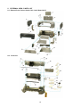
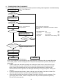
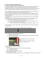
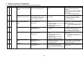
1
iP2000
SIMPLIFIED SERVICE MANUAL
1. PRODUCT LIST
2. PRODUCT SPECIFICATIONS
3. ERROR DISPLAY
4. ADJUSTMENT / SETTINGS
5. EXTERNAL VIEW / PARTS LIST
6. TROUBLESHOOTING FLOWCHART
7. SPECIAL NOTES ON SERVICING IN ASIA
8. PRODUCT TECHNICAL INFORMATION
APPENDIX 1: SERVICE TEST PRINT 1 PRINT SAMPLE
APPENDIX 2: iP2000 EEPROM INFORMATION PRINT SAMPLE
QY8-13A1-000
Rev. 00
August 6, 2004
Canon Inc.
1
1. PRODUCT LIST
1-1. Main Units
Product name
Canon Bubble Jet Printer
iP2000
Product code
Sales territory
9318A001AA
US
9318A002AA
CA
9318A003AA
LAM LVT
9318A004AA
LAM HVT
9318A005AA
EMB
9318A005AB
EMB
9318A008AA
ASA HVT
9318A009AA
AU
9318A010AA
KR
9318A011AA
GB
9318A012AA
JP
9318A013AA
TW
9318A014AA
HK
9318A015AA
CN
9318A017AA
EUM
Remarks
1-2. Options
None
1-3. Consumables
Product name
Product code
Sales territory
Canon Ink Tank
BCI-24 Black
6881A001AA
6881A002AA
6881A003AA
6881A004AA
JPN
EUR
USA/CAN
ASIA/AUST
Canon Ink Tank
BCI-24 Color
6882A001AA
6882A002AA
6882A003AA
6882A004AA
JPN
EUR
USA/CAN
ASIA/AUST
Canon Ink Tank
BCI-24 Black Twin Pack
6881A008AA
6881A009AA
6881A010AA
6881A011AA
JPN
EUR
USA/CAN
ASIA/AUST
Canon Ink Tank
BCI-24 Color Twin Pack
6882A008AA
6882A009AA
6882A010AA
6882A011AA
JPN
EUR
USA/CAN
ASIA/AUST
2
Remarks
In common with the
S200, S200x,
S300, S330, i320,
i350, i355, i250,
i255, iP1000, and
iP1500.
2. PRODUCT SPECIFICATIONS
2-1. Printer Main Unit Specifications
Paper feeding method
Resolution
Printing speed (ASF)
ASF and front sheet feeder
4,800 x 1,200 dpi (max.)
Draft
Standard
BK (FINE_BK)
20 ppm
14.4 ppm
CL (FINE_CL)
14 ppm
7.3 ppm
Bi-directional / Uni-directional (automatically switched according to print
data and print mode)
50% duty
203.2 mm (8 inches), 216.0 mm (8.5 inches) in borderless printing
USB (2.0) Full Speed only
Service part: QY6-0054-000
Printing direction
Draft mode print duty
Print width
Interface
Supported print head
Number of pages that can be printed
CL
BK
Stacking capacity (ASF, front sheet feeder)
Plain paper
High Resolution Paper (HR-101)
Glossy Photo Paper (GP-401)
Photo Paper Pro (PR-101)
Photo Paper Plus Glossy (PP-101)
Matte Photo Paper (MP-101)
Photo Paper Plus Double Sided (PP-101D)
Manual duplex printing is supported.
Photo Paper Plus Semi-gloss (SG-101)
Transparency (CF-102)
T-shirt Transfer (TR-301)
Envelope
Photo Stickers (PS-101)
Borderless printing
Detection function
Cover open
Presence of print head
Presence of ink tank
Presence of paper
Paper width
Waste ink absorber full
Remaining ink amount
Approx. 170 pages (SCID No.5 pattern, default print mode)
Approx. 520 pages (SCID No.5 pattern, default print mode)
Approx. 300 pages (1,500-character pattern, default print mode)
Max. 13 mm (Approx. 150 pages of 64 g/m2)
ASF
Front sheet feeder
2
13 mm or less (64 to 105 g/m2)
13 mm or less (64 to 105 g/m )
13 mm (approx. 80 sheets) or less 13 mm (approx. 80 sheets) or less
A4, LTR:
10 sheets or less A4, LTR: 10 sheets or less
4x6, Credit Card: 20 sheets or less
A4, LTR, 5x7:
10 sheets or less A4, LTR: 10 sheets or less
4x6:
20 sheets or less
A4, LTR, 5x7:
10 sheets or less A4, LTR: 10 sheets or less
4x6:
20 sheets or less
A4, LTR:
10 sheets or less A4, LTR: 10 sheets or less
A4, 5x7:
1 sheet
A4, LTR: 10 sheets or less
(Printing on the front side of paper
in duplex printing can be
performed from the front sheet
feeder.)
A4, LTR, 5x7:
10 sheets or less A4, LTR: 10 sheets or less
4x6:
20 sheets or less
1 sheet
1 sheet
1 sheet
1 sheet
COM#10, DL:
10 sheets or less Not feedable.
1 sheet
Not feedable.
Up to A4, LTR
Available
Available
Not available
Available
Not available
Available
Available (Detected by dot counting. Reset by user operation. Enabled
at default.)
Available (11 types)
Print head alignment
Acoustic noise level
Fine (Photo Paper Pro / Fine mode)
HQ
HS
Approx. 43 dB (Sound pressure level ISO9296)
Approx. 44 dB
Approx. 53 dB
During operation
Temperature:
Humidity:
Temperature:
Humidity:
Environmental requirements
Non-operation
Power supply
Input voltage / Frequency
Power consumption:
During printing
Stand-by status
5C to 35C (41F to 95F)
10% to 90%RH (no condensation)
0C to 40C (32F to 104F)
5% to 95%RH (no condensation)
AC 100 to 127 V, 50/60Hz (LV)
AC 220 to 240 V, 50/60Hz (HV)
Approx. 11 W
Approx. 2 W
3
(2-1. Printer Main Unit Specifications cont’d)
External dimensions
With the paper support and front sheet feeder
extended
With the paper support and front sheet feeder
retracted
Weight
Related standards
Approx. 418 (W) x 510 (D) x 315 (H) mm
Approx. 418 (W) x 260 (D) x 169 (H) mm
Approx. 4.4 kg (excluding the print head and ink tanks)
Electromagnetic radiance
Electrical safety
Environmental regulations
VCCI, FCC, IC, CE Mark, Taiwan EMC, C-Tick, CCC (EMC), Korea
MIC, Gost-R
DENAN, UL, C-UL, CB Report, CE Mark, GS, Gost-R, FT, SASO, CCC,
SPRING, Korea EK, IRAM
RoHS (EU), WEEE (EU), Korea Package Recycle Law, Green Point
(Germany), Energy Star, Eco Mark, Law on Promoting Green
Purchasing
Note: Not Blue Angel compliant.
2-2. Product Life
Specified print volume or the years of use, whichever comes first.
- 3 years of use
- Print volume: 4,000 pages
- Black: 2,000 pages (A4, standard mode, 1,500-character pattern)
- Color: 1,200 pages (A4, 7.5% duty per color pattern)
120 pages (A4, photo, borderless printing)
80 pages (4 x 6, photo, borderless printing)
600 pages (Postcard, photo, borderless printing)
Note: The above print volume breakdown is estimated using average user consumption
patterns.
2-3. Print Head Specifications
Type
4-color integrated type (ink tank separate type)
Print head
BK:
320 nozzles in 2 vertical lines
C/M/Y:
128 nozzles in 2 vertical lines per color
Ink droplet: BK 30 pl, CL 5 pl / 2 pl
Ink color
BK (pigment-based ink)
CL: Y, M, C (high brilliance)
Ink tank
BCI-24 Black, BCI-24 Color
Weight
Approx. 58g (excluding ink tanks)
Supply method
Service part (excluding ink tanks)
Part number: QY6-0054-000
Print head life
4,000 pages (Same as the printer main unit)
Note: - The print head is in common with the iP1500.
- Although the print head can be physically installed in the i350, i355, i250, i255, S300, S330,
and iP1000 series printers, it is incompatible with and cannot be used in those models.
4
3. ERROR DISPLAY
Errors are displayed by the LEDs, and ink low warnings are displayed by the Status Monitor.
3-1. Operator Call Error (LED Blinking in Orange)
LED
blinking
Error
Corrective action
2 times
Paper out
3 times
Paper jam
4 times
5 times
Ink tank not installed
Print head not installed or failure has
occurred in the print head.
(Non-supported print head (see page 4) is
installed or print head EEPROM data is
abnormal.)
Waste ink absorber full or platen waste ink
absorber full warning (approx. 95% of the
maximum capacity)
Non-supported digital camera or digital
video camera is connected.
8 times
9 times
Set paper, and press the Resume/Cancel button
to feed the paper.
Remove the jammed paper, and press the
Resume/Cancel button.
Re-install the ink tanks, and close the front cover.
After confirming that the print head is for the
iP2000 (QY6-0054), re-install the print head, and
close the front cover.
If not recovered, with the print head installed,
power the printer off and on.
Pressing the Resume/Cancel button will exit the
error, and enable printing.
After removing the cable between the printer and
the camera, press the Resume/Cancel button, and
re-connect the cable. If the error is not resolved,
the connected camera may not be supported for
Camera Direct Printing. Check that a supported
camera is connected.
3-2. Service Call Error (LED Blinking in Orange and Green Alternately)
LED
Error
Corrective Action
blinking
2 times
Carriage error
Turn the printer off and on again. If the error is not resolved,
replace the printer.
3 times
LF error
Turn the printer off and on again. If the error is not resolved,
replace the printer.
4 times
Purge unit error
Turn the printer off and on again. If the error is not resolved,
replace the printer.
5 times
ASF cam sensor error
Turn the printer off and on again. If the error is not resolved,
replace the printer.
6 times
Internal temperature error Turn the printer off and on again. If the error is not resolved,
replace the printer.
7 times
Waste ink absorber full or Replace the printer. (In waste ink absorber replacement, perform
platen waste ink absorber the EEPROM information print to identify if the main and/or platen
full
waste ink absorber should be replaced. After replacement, reset
the applicable waste ink counter(s).)
8 times
Print head temperature
Turn the printer off and on again. If the error is not resolved,
rise error
replace the printer.
9 times
EEPROM error
Turn the printer off and on again. If the error is not resolved,
replace the printer.
13 times PF position error
Turn the printer off and on again. If the error is not resolved,
replace the printer.
14 times PF cam sensor error
Turn the printer off and on again. If the error is not resolved,
replace the printer.
17 times Motor driver error
Turn the printer off and on again. If the error is not resolved,
replace the printer.
5
3-3. Ink Low Warning (Ink low warnings are displayed by the Status Monitor only when the
remaining ink level detection is enabled, and no Status Monitor display when disabled.)
Note: The Status Monitor display in the table below is for Windows.
Warning
Display by Status Monitor
Ink low warning 1 (approx. half level)
Ink low warning 2 (low remaining ink)
Ink low warning 3 (ink level unknown)
6
4. ADJUSTMENT / SETTINGS
4-1. User Mode
Function
Print head manual
cleaning
Print head deep
cleaning
Paper feed roller
cleaning
Bottom plate cleaning
(cleaning of ink mist
on the platen ribs)
Nozzle check pattern
printing
Print head alignment
Procedures
- Cleaning both black and color:
See “Standalone printer operation” below.
- Cleaning black or color separately, or
both black and color:
Perform from the printer driver’s
Maintenance tab.
- Cleaning black or color separately, or
both black and color:
Perform from the printer driver’s
Maintenance tab.
1) Using the Paper Feed switch, select the
sheet feeder unit to perform paper feed
roller cleaning.
2) Remove all paper from the selected sheet
feeder unit.
3) Perform paper feed roller cleaning,
following the “Standalone printer
operation” procedures below.
1) Fold a sheet of plain paper (A4 or letter)
in half crosswise, then unfold and set it in
the ASF with the folded ridge facing
down.
2) Perform bottom plate cleaning, following
the “Standalone printer operation”
procedures below.
3) When the folded ridge of the ejected
paper is NOT soiled, cleaning is
completed. If it is soiled, repeat the steps
1) and 2).
See “Standalone printer operation” below.
Remarks
If the paper feed roller cleaning is
not effective, manually clean the
rollers with a cloth slightly
dampened with water.
If soiling on the paper persists
after the bottom plate cleaning is
performed 3 times, manually
clean the platen ribs with a cotton
swab.
Also available from the printer
driver’s Maintenance tab.
1) Perform from the printer driver’s
Maintenance tab.
2) According to the printout, set the optimum
values.
<Standalone printer operation>
1) Turn on the printer.
2) Press and hold the Resume/Cancel button until the LED blinks the specified number of times
listed in the table below, and release it. The operation starts.
LED blinking
Operation
Remarks
1 time
Print head manual cleaning
2 times
Nozzle check pattern printing
3 times
Paper feed roller cleaning
4 times
Unspecified
5 times
Bottom plate cleaning
6 times
Unspecified
7
4-2. Service Mode
Function
EEPROM information print
- Destination
- ROM version
- Waste ink amount
- Total number of sheets fed
EEPROM initialization
Procedures
Remarks
See “Service mode operation
procedures” below.
Set a sheet of A4-, letter-, or larger-sized
paper.
For print sample, see APPENDIX 2, iP2000
EEPROM INFORMATION PRINT SAMPLE.
See “Service mode operation
procedures” below.
The following items are NOT initialized:
- Destination settings
- Waste ink counters
The following 3 methods are available:
- Resetting the main waste ink counter (0%)
- Re-setting the main waste ink counter
value to 50%
- Resetting the platen waste ink counter
(0%)
Waste ink counter reset
See “Service mode operation
procedures” below.
Destination settings
See “Service mode operation
procedures” below.
See “Service mode operation
procedures” below.
Print head deep cleaning
<Service mode operation procedures>
1) With the front cover closed, and the printer power turned off, while pressing the Resume/Cancel
button, press and hold the Power button. (DO NOT release the buttons. The LED lights in green
to indicate that a function is selectable.)
2) While holding the Power button, release the Resume/Cancel button. (DO NOT release the
Power button.)
3) While holding the Power button, press the Resume/Cancel button 2 times, and then release
both the Power and Resume/Cancel buttons. (Each time the Resume/Cancel button is pressed,
the LED lights alternately in orange and green, starting with orange.) During initial operations,
the LED blinks in green.
4) When the LED light sin green, press the Resume/Cancel button the specified number of time(s)
according to the function listed in the table below. (Each time the Resume/Cancel button is
pressed, the LED lights alternately in orange and green, starting with orange.)
Time(s)
LED
Function
Remarks
0 times
Green
Power off
When the print head is not installed, the
carriage returns and locks in the home
position.
1 time
Orange
Service test print
2 times
Green
EEPROM information print
3 times
Orange
EEPROM initialization
4 times
Green
Waste ink counter resetting
Proceed to the step 5), and follow the
Waste ink counter reset procedures.
5 times
Orange
Destination settings
Proceed to the step 5), and following the
Destination settings procedures.
6 times
Green
Print head deep cleaning
7 to 9 times Orange
Not used in servicing
10 times
Green
Return to the menu selection
5)
After the function (menu) is selected, press the Power button. The LED lights in green, and the
selected function is performed. (When the operation completes, the printer returns to the menu
selection mode automatically.)
8
<Waste ink counter reset procedures>
In the waste ink counter resetting mode, press the Resume/Cancel button the specified number of
time(s) according to the ink counter reset value listed in the table below, and press the Power button.
Time(s)
LED
Waste ink counter value
0 times
Green
Reset the main waste ink counter (0%).
1 time
Orang
Reset the platen waste ink counter (0%)
e
2 times
Green
Re-set the main waste ink counter value to 50%.
<Destination settings procedures>
In the destination settings mode, press the Resume/Cancel button the specified number of time(s)
according to the destination listed in the table below, and press the Power button.
Time(s)
LED
Destination
0 times
Green
No change
1 time
Orang
Japan
e
2 times
Green
Other than Japan (A4)
3 times
Orang
Other than Japan (LTR)
e
9
5. EXTERNAL VIEW / PARTS LIST
5-1. External Parts, Power Supply Unit, Logic Board Ass’y
5-2. Print Unit
10
Parts List
Key
1
Part Number
Rank
Q'ty
Description
QY6-0054-000
K
1
PRINT HEAD
QC1-5041-000
J
1
PAPER SUPPORT TRAY
Remark
Common
parts
B
2
QC1-5040-000
J
1
PAPER SUPPORT
3
QM2-1674-000
J
1
UPPER COVER UNIT
4
QC1-5038-000
J
1
SIDE COVER L
5
QC1-5039-000
J
1
SIDE COVER R
6
QC1-5055-000
J
1
PANEL COVER R
7
QC1-5056-000
J
1
PANEL COVER L
8
QC1-5037-000
J
1
ACCESS COVER
9
QM2-1735-000
I
1
LOGIC BOARD ASS’Y
10
QC1-5042-000
J
1
OUTPUT TRAY
11
QC1-5043-000
J
1
EXTENTION OUTPUT TRAY
12
QC1-5052-000
J
1
OUTPUT TRAY HOLDER
13
QM2-1672-000
J
1
BASE COVER UNIT
14
QM2-1673-000
J
1
FRONT COVER
QK1-0927-000
I
1
AC ADAPTER: 100/120V 50/60HZ
LV
QK1-0930-000
N
1
AC ADAPTER: 220/240V 50/60HZ
HV (EUR/ASIA/AU/KR/HK/GB/EUM)
QC1-5005-000
J
1
EMBLEM (E)
B
QC1-5009-000
J
1
EMBLEM (J)
B
QC1-5111-000
J
1
PIXMA LABEL (E)
15
16
17
18
QC1-5104-000
I
1
TIMING SLIT STRIP FILM
19
QC1-5106-000
I
1
TIMING SLIT STRIP FILM SPRING
20
QC1-5080-000
J
1
PAPER FEED GUIDE COVER
21
QM2-1678-000
I
1
CAP UNIT
22
QC1-5024-000
I
1
BLADE LOCK LEVER
23
QM2-1676-000
I
1
BLADE UNIT
24
QC1-5022-000
I
2
INK ABSORBER1
25
QC1-5105-000
I
2
INK ABSORBER2
26
QC1-5023-000
I
1
INK ABSORBER3
27
QC1-5021-000
I
1
INK ABSORBER4
28
QC1-5020-000
I
1
INK ABSORBER5
29
QC1-5007-000
I
1
S1
XA9-1493-000
G
B
PLATEN ABSORBER
SCREW, TP M3x8
FOR UPPER CASE UNIT
A
FOR PRINT UNIT
S2
XB6-7300-805
G
SCREW, TP BH3x8
FOR PRINT UNIT
FOR AC ADAPTER
FOR BASE COVER UNIT
S3
XB1-7300-605
G
SCREW, MACHINE WASHER HEAD M3x6
FOR LOGIC BOARD ASS’Y
A
Power cables:
QH2-2720-000
S
1
CORD, POWER
120V (LAM-LV)
A
QH2-2724-000
S
1
CORD, POWER
100V-120V (JP)
B
QH2-2725-000
S
1
CORD, POWER
100V-120V
A
QH2-2726-000
S
1
CORD, POWER
220V-240V
A
QH2-2727-000
S
1
CORD, POWER
220V-240V (AU)
A
WT3-5156-000
S
1
CORD, POWER
220V-240V (GB, HK)
A
WT3-5160-000
S
1
CORD, POWER
220V-240V (KR)
A
WT3-5182-000
S
1
CORD, POWER
220V-240V (CHN)
A
A: In common with the iP1500 and iP1000
B: In common with the iP1500
11
6. TROUBLESHOOTING FLOWCHART
6-1. Printer Main Unit Troubleshooting Flowchart (how to confirm printer operation at refurbishment)
Service mode
Service Call
Error?
See 4-2. Service Mode for
details.
Yes
No
Open front cover,
and install print head
Service Call
Error?
Yes
No
Service test print
Correct?
Yes
<Service test print check items>
(See APPENDIX 1, SERVICE TEST PRINT 1 PRINT
SAMPLE.)
See 4-2. Service Mode for
printing method.
No
1. Non-ejection of ink:
2. Top of form:
3. Vertical lines:
4. Gray area:
Replace print head and
perform service test print
Correct?
Yes
Off the paper
Not connected
White lines / uneven density
No
Yes
Main waste ink counter
less than 7%?
Yes
No
Visually check the platen waste ink
absorber, and replace it if it is
soiled.
EEPROM initialization
Power off
Normal
Defective
<Note for normal printer refurbishment>
At end of refurbishment, set the printer to the default shipment conditions (with the paper lifting plate
in the raised position, and the carriage locked in the print head replacement position), following the
steps below.
1. Install the print head, and while pressing and holding the Power button, connect the AC plug.
After the LED lights in green, with the Power button still pressed, press the Resume/Cancel
button 2 times, and release both the Power and Resume/Cancel buttons. (Each time the
Resume/Cancel button is pressed, the LED lights alternately in orange and green, starting with
orange.)
2. Press the Resume/Cancel button 4 times, and then press the Paper Feed switch 2 times. The
shipment inspection pattern is printed, and the EEPROM is initialized.
3. After removing the print head, press the Paper Feed switch 2 times to turn off the printer. (The
paper lifting plate is raised, and the carriage moves to the print head replacement position.)
DO NOT print after this point.
12
NG
NG
NG
NG
6-2. Print Head Troubleshooting Flowchart (print head operation confirmation)
Connect to computer
Nozzle check pattern printing
Yes
Correct?
No
Print head cleaning
Nozzle check pattern printing
Yes
Correct?
No
Print head deep cleaning
Nozzle check pattern printing
Correct?
Yes
No
Print head deep cleaning
Nozzle check pattern printing
Correct?
Yes
No
Replace ink tanks
Nozzle check pattern printing
Correct?
Yes
No
Normal
Defective
13
7. SPECIAL NOTES ON SERVICING IN ASIA
7-1. Resetting the Main and Platen Waste Ink Counters
The iP2000 has separate waste ink counters for the main waste ink absorber and the platen waste
ink absorber, respectively. At waste ink absorber replacement, in the service mode, reset the
applicable waste ink counter according to the replaced waste ink absorber. (When both the main and
platen waste ink absorbers are replaced, reset both the main and platen waste ink counters.)
For the main waste ink absorber, a new design has been adopted so that a half portion of the main
waste ink absorber can be replaced just by removing the printer housing.
When compared with replacement of the entire main waste ink absorber, replacement of the half
portion is extremely simple and easy, as it does not require removal of other components such as
the chassis and ASF.
The printable number of pages after replacement of the half portion of the main waste ink absorber
is 2,000 pages.
According to the above, 2 methods are available for replacement of the main waste ink absorber,
and the main waste ink counter should be reset according to the replacement method.
- Replacement of the half of the main waste ink absorber:
Easy, and the printable number of pages after the replacement is approx. 2,000.
- Replacement of the entire main waste ink absorber:
Difficult, and the printable number of pages after the replacement is approx. 4,000.
After replacement, the main or platen waste ink counter should be reset according to the replaced
absorber portion.
<Waste ink counter value to be re-set to after waste ink absorber replacement>
Replaced waste ink absorber
Waste ink counter value
Entire main waste ink absorber
Reset the main waste ink counter (0%).
Half of the main waste ink absorber* Re-set the main waste ink counter value to 50%.
Entire platen waste ink absorber
Reset the platen waste ink counter (0%).
* How to replace half of the main waste ink absorber:
1. Remove the upper cover unit.
2. Replace the 4 ink absorbers (2 types, equivalent to half of the main waste ink absorber),
shown in the figure below.
Replaceable half portion (4 ink absorbers)
After the half portion is replaced, re-set the
waste ink counter to 50%.
<Waste ink absorber replacement procedures>
1. Error check
Perform EEPROM information printing, and check the following values:
- D:
Main waste ink counter
- PD: Platen waste ink counter
2. Replace the applicable waste ink absorber(s).
3. Reset the waste ink counter.
For waste ink counter resetting procedures, see 4. ADJUSTMENT / SETTINGS, 4-2. Service Mode.
14
8. PRODUCT TECHNICAL INFORMATION
8-1. FAQ (Problems specific to the iP2000 and corrective actions)
No.
1
*
A
Function
Phenomenon
Installation Carriage error (LED blinks
alternately in orange and green
2 times).
2
A
Ink tank installation error
(LED blinks in orange 4 times.)
3
B
4
Possible Call / Claim
Corrective action
- LED blinks alternately in orange and Remove the packing material fixing the
green, 2 times (carriage error).
carriage.
Cause
The user may not have removed the
packing material at unpacking and
installation.
Although a caution sheet is packaged
together with the printer, the user may not
have noticed it.
Note: Even if the packing material
remains, no parts are damaged.
Open the access cover, and install the ink Since the user did not seat the ink tanks
- LED blinks in orange 4 times (ink
tanks properly.
completely at unpacking, installation, or
tank installation error). (As this
ink tank replacement, the ink tank
occurs at printer installation, the user
contacts the main case.
cannot recognize the error.)
No paper feeding (due to
incorrect Paper Feed switch
setting)
- Paper out error
- Paper cannot be fed
- Cannot print
B
Multi-feeding
- Multiple pages of paper are fed
simultaneously.
-Blank paper is ejected.
5
B
Envelope not feeding
- Paper out error
- Paper cannot be fed
- Cannot print
6
B
Credit Card size paper jam at
feeding
- Paper jam error
- Paper cannot be fed
- Cannot print
7
C
Paper jam
- Paper jam error
- Paper cannot be fed
- Cannot print
Paper
feeding
15
The paper feed roller slips on the paper at
paper feeding, or the Paper Feed switch
setting is not correct.
Note: Camera Direct Printing is available
only when paper feeds from the
ASF.
In the high temperature and high humidity
environment, the frictional force between
the front and back sides of paper
becomes high, and sheets stick to each
other, contributing to multi-feeding.
1. Perform roller cleaning from the printer The paper feed roller slips on the paper at
paper feeding.
driver.
Note: Depending on the paper lots. This
2. Clean the paper feed roller with
phenomenon may occur in DL
moistened cloth.
envelope.
3. Reduce the number of envelopes
loaded in the ASF.
4. Flatten the envelope (with a pen).
Set a sheet of Credit Card size paper in When Credit Card size paper is set with
the shorter edge in vertical orientation,
the ASF with the longer edge in vertical
the paper does not reach the LF roller,
orientation, and press the
and the paper is not fed.
Resume/Cancel button.
When using the ASF, remove the jammed As the LF roller slips on the paper, the
paper is not fed, causing the jam error at
paper from the paper pick-up side.
When using the front sheet feeder, open paper ejecting.
the rear cover, and remove the jammed
paper.
1. Perform roller cleaning from the printer
driver.
2. Change the paper feed method by the
Paper Feed switch.
3. Clean the paper feed roller with
moistened cloth.
1. Fan the paper and set them.
2. In case of PR-101, set the paper sheet
by sheet.
(8-1. FAQ (Problems specific to the iP1000 and corrective actions) cont’d)
No.
8
*
B
9
Function
Image
quality
Phenomenon
Smearing on printed side.
Possible Call / Claim
- Smear on the printed side of paper
- Cannot print properly
- Paper edge crease
B
Smearing on the backside, or
address side of postcards
10
C
Horizontal lines or uneven print
density at the trailing edge of
paper
<Photo Paper Plus Double Sided>
- Smears on the already printed side
when printing the other side
<When printing the address side of
postcards>
- Smears on the address side
<When printing the message side of
postcards>
- Smears on the backside
1. Recommend printing in the print
- Cannot print to the bottom edge of
quality assurance area.
paper
- Lines or uneven print density appear 2. Change the print quality from standard
to high mode.
in the trailing edge of paper
3. Try other paper (PP-101)
- Cannot print properly
11
C
Horizontal lines or uneven print
density due to LF roller feeding
at small pitch
- Lines or uneven print density (on
skin tones and background)
- Cannot print properly
Corrective action
1. Correct the paper curl.
2. Change the paper thickness lever
setting.
3. Recommend the user to conduct
printing in the print quality assurance
area.
1. Perform bottom plate cleaning from
the printer driver.
2. Clean the ribs on the platen with
cotton swabs/buds.
When borderless printing is conducted
continuously, ink mist attaches to the ribs
on the platen, and is transferred to the
backside of the following paper.
When the paper end comes off the pinch
roller, printing is performed without the
paper being held, preventing the ink
drops from being ejected in the correct
positions, resulting in unevenness.
Note: The problem is less noticeable
than that of the i320.
Change the print quality from standard to As the print media slightly slips while
high mode.
being fed by the LF roller, printed areas
overlap, causing the problem.
*Occurrence level:
A: The phenomenon is likely to occur frequently. (Caution required).
B: The phenomenon may occur under certain conditions, but likeliness is assumed very low in practical usage.
C: The phenomenon is unlikely to be recognized by the user, and no practical issues are assumed.
16
Cause
The edge of paper rises due when paper
is curled, causing the print head to rub
against the printed surface of paper,
resulting in smearing.
8-2. Major Functions
(1) Borderless printing (up to A4 and LTR sizes)
<Possible problems with this function>
- Smearing on the address side of postcards in continuous borderless printing on the message side.
-> Perform bottom plate cleaning, and clean the ribs on the platen.
- Smearing on the backside of paper in continuous borderless printing.
-> Perform bottom plate cleaning, and clean the ribs on the platen.
- Ink mist on the platen.
-> Perform bottom plate cleaning, and clean the ribs on the platen.
(2) 2 types of paper path feeding (paper feeding from the ASF and front sheet feeder)
The printer has 2 paper feeding methods, from the ASF and from the front sheet feeder.
Paper feeding from the front sheet feeder does not support,
- paper size smaller than A5,
- Camera Direct Printing, and
- printing on the back side of paper in duplex printing.
<Possible problems with this function>
- “No paper” error due to incorrect Paper Feed switch setting (such as when the Resume/Cancel
button is pressed after Paper Feed switch setting).
Printer driver default setting:
Paper Source is set to Paper Feed Switch.
Printer’s Paper Feed switch default setting: ASF
Paper feed setting priority: Printer driver setting over printer’s Paper Feed switch setting
- Paper feed problem due to incorrect paper size setting (the front sheet feeder supports only A5- or
larger-sized paper).
(3) Remaining ink level detection function
The printer has a function to detect the remaining ink level. (Default setting: ON)
Detection method: Dot counting (Counted for each BK/CL ink tank)
CL tank: The remaining ink level is detected by total counted dot values of 3
colors of ink.
Display method: Displayed on the Status Monitor (at 3 levels listed below for each BK/CL ink tank)
Level 1: Half level of remaining ink level (Approx. 40% of ink remaining)
Level 2: Indication of “!” mark (Approx. 10% of ink remaining)
Level 3: Indication of “?” mark (Remaining ink level is unknown, ink may be
used up anytime)
Note: Remaining ink detection function displays the status only, and does not
cause errors.
Accuracy:
The margin of error of detection accuracy is +/-10% in normal printing.
The margin of error is likely to be large in the following specific print patterns:
When printing continuously using any one of the CMY colors of ink
-> As the remaining ink level is calculated by total counted dot values of 3
colors of ink, if any of the C/M/Y inks is heavily consumed, the margin of
error for remaining ink increases.
When performing continuous BK solid printing
-> With continuous printing, ink flow from the tank to the ink chamber can be
interrupted, after which ink remains unused in the tank.
Reset procedure: Perform the following operations from the printer driver’s Maintenance tab:
1. In Low Ink Warning Setting, enable Display low ink warning.
2. In Ink Counter Reset, reset the applicable ink counter(s).
Note: Be sure to reset the ink counter from the printer driver’s Maintenance tab
after replacing ink tanks.
17
<Possible problems with this function>
- Due to user error, the actual remaining ink level does not match the indicated remaining ink level,
resulting in “ink out”, etc.
User error: Forgetting to reset the ink counter / ink counter reset other than when replacing ink
tanks.
- Due to the specific print pattern, the actual remaining ink level does not match the indicated
remaining ink level, resulting in “ink out”.
Specific print pattern: Continuous printing using any one of the CMY colors of ink / continuous
BK solid printing, etc.
(4) Print head deep cleaning
The printer has a print head deep cleaning (refreshing) function.
Print head deep cleaning (refreshing):
This is a deep cleaning function in order to resolve print failure due to ink clogging
the print head. (The black ink is pigment-based, and clogs easier than other
dye-based ink.)
Perform from the printer driver’s Maintenance tab.
<Possible problems with this function>
- Excessive ink consumption when conducting print head deep cleaning repeatedly. (The amount of
ink used is approx. 10 to 15 times the normal manual cleaning amount.)
<Reference> Cleaning types, amount of ink used, and time required
BK and CL ink drawing is simultaneously performed.
Cleaning type
Amount of ink used
Manual cleaning
BK: Approx. 0.12 g
Dot count cleaning
CL: Approx. 0.14 g
Cleaning on arrival at user
Print head replacement
BK: Approx. 0.42 g
Timer cleaning (24 hours to 3 months)
CL: Approx. 0.52 g
Cleaning when the print head is not capped at printer power on
Ink tank replacement
BK: Approx. 0.57 g
CL: Approx. 0.62 g
Print head deep cleaning
BK: Approx. 1.50 g
Timer cleaning (3 months or more)
CL: Approx. 2.35 g
Time required
Approx. 40 sec.
Approx. 60 sec.
Approx. 60 sec.
Approx. 70 sec.
(5) Print head alignment
The printer has a print head alignment function (print head position adjustment function). As it is not
necessary to perform print head alignment at setup or installation of the printer, the function is only briefly
introduced at installation.
Print head alignment: This is a function to correct displacements between the nozzle lines of the
print head, and incorrect print position at bi-directional printing.
The adjustment is conducted using the printed head position adjustment
pattern.
A: Print head alignment between black even and odd nozzles
B: Print head alignment between cyan even and odd large nozzles
C: Print head alignment between magenta even and odd large nozzles
D: Print head alignment between cyan even and odd small nozzles
E: Print head alignment between magenta even and odd small nozzles
F: Print head alignment in bi-directional black printing
G: Print head alignment of large nozzles in color bi-directional printing
H: Print head alignment between black and photo black nozzles
18
I: Print head alignment of small nozzles in color bi-directional printing
J: Print head alignment between cyan large and small nozzles
K: Print head alignment between magenta large and small nozzles
Perform from the printer driver’s Maintenance tab.
(At initial set-up by the user, notice to perform the print head alignment is
displayed in the Status Monitor.)
<Possible problems with this function>
- The line is not straight.
-> Perform print head alignment from the printer driver.
- Printout is granulated.
-> Perform print head alignment from the printer driver.
19
APPENDIX 1:
SERVICE TEST PRINT 1 PRINT SAMPLE
Check item 1 (Non-ejection of ink): Total area of the sample below
Check item 2 (Top of form)
EEPROM information print
-> See below for details.
BK nozzle check pattern
C nozzle check pattern (5 pl)
M nozzle check pattern (5 pl)
Y nozzle check pattern (5 pl)
C nozzle check pattern (2 pl)
M nozzle check pattern (2 pl)
Y nozzle check pattern (2 pl)
Check item 3 (Gray area)
Check item 4 (Vertical lines)
Paper size: A4
<EEPROM information print>
Model name
ROM version
USB No.
Line inspection information
Main waste ink absorber ink amount (%)
IP_2000
V X.XX USB(XXXXX)
FA=XX XX XX
D=XXX.X
20
APPENDIX 2:
iP2000 EEPROM INFORMATION PRINT SAMPLE
Print sample:
iPXXXX V1.03 IF(USB=1) D=004.5 PD=000.0 ST=2001/09/27-18:30
ER(ER0=1000 ER1=5100 ER2=0000 ER3=0000) LPT=2001/09/09-09:09
PC(M=002 R=00 T=0001 D=009 C=000)
CLT(BK=2001/09/27-18:30 CL=2001/09/27-18:30)
CH=00002 DC(BK1=040 CL=000)
IC(BK1=00001 C=00001 M=00001 Y=00001)
P_ON(S=00009 h=00005) REG=1
UR(A(BKoe)=+01 B(Coe)=-01 C(Moe)=+01 D(SCoe)=-01 E(SMoe)=+01 F(BKbi)=+01
G(CLbi)=+01 H(BK-PCBK)=+01 I(SCLbi)=+01 J(C-SC)=+01 K(M-SM)=+01)
WP=00024 CDIN(LG=000 PB=000) MSD(015)
PAGE(All=00083 PP=00035 HR+MP=00003 PR+SP+SG=00000 GP=00000 PC=00000 EVN=00000)
UCPAGE(All=00083 PP=00035 HR+MP=00003 PR+SP+SG=00000 GP=00000)
CDPAGE(All=000) EDGE=00083 L=00000 2L=00000
Head TempBK=18.5 Head TempC=17.5 Env Temp=30.0 FF(3F 3F 3F)
HDEEPROM
V0001
SN=0000-0EA5
LN(00000 00000 00001 00003 00013 00017 00015)
ID=03
IL=(BK=000 C=+01 M=000 Y=+01 C2=+01 M2=+01 Y2=+01)
Printed items:
1. Model name
2. ROM version 3. Connected I/F (USB1) 4. Waste ink amount/Platen waste ink amount
Installation date
6. Operator call/service call error record 7. Last printing time
8. Purging count (manual/deep cleaning/timer/dot count/ink tank or print head replacement)
9. Cleaning time (BK/CL)
10. Print head replacement count 11. Number of times the dot count values are reset (pigment BK1/CL)
12. Total ink consumption (pigment BK/C/M/Y)
13. Power-on count (soft/hard) 14. Print head alignment by user
15. User print head alignment values (Bkoe/Coe/Moe/SCoe/SMoe/BKbi/CLbi/BK-PCBK/SCLbi/C-SC/M-SM)
5.
16. Wiping count 17. Camera Direct Print-supported device connection count (PictBridge/legacy)
18. Longest period
where printing stops
19. ASF feed pages (total, plain paper, High Resolution Paper & Matte Photo Paper, Photo Paper Pro & Photo Paper
Plus Glossy & Photo Paper Plus Semi-gloss, Glossy Photo Paper, postcard, envelope)
20. U-turn cassette feed pages (total, plain paper, High Resolution Paper & Matte Photo Paper, Photo Paper Pro & Photo
Paper Plus Glossy & Photo Paper Plus Semi-gloss, Glossy Photo Paper)
21. Camera Direct print pages (total) 22. Borderless print pages (total) 23. L-size & 4x6 print pages 24. 2L-size &
5x7 print pages 25. Print head temperature (BK/CL) 26. Inside temperature 27. Line inspection information
HDEEPROM
28. Version
29. Serial number
30. Lot number
31. Print head ID
32. Ink ejection level (BK/C/M/Y/C2/M2/Y2)
21