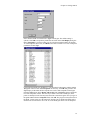
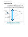
1
Cambridge Aero Explorer™ for Windows®
Version 1.0
User’s Guide
Cambridge Aero Explorer User’s Guide
Copyright
Copyright© 2001 by Cambridge Aero Instruments All Rights Reserved
First Edition 2001
Trademarks
Aero Explorer is a trademark of Cambridge Aero Instruments.
Microsoft and Windows are registered trademarks of the Microsoft Corporation.
All other trademarks or registered trademarks are owned by their respective holders.
Mailing address:
Cambridge Aero Instruments
P.O. Box 1420
Waitsfield, VT 05673
USA
Shipping address:
Cambridge Aero Instruments
1673 Main St.
Waitsfield, VT 05673
USA
Telephone: 01-802-496-7755
Fax: 01-802-496-6235
Email: [email protected]
Website: www.cambridge-aero.com
Cambridge Aero Explorer User’s Guide
Table of Contents
Chapter 1. Introduction................................................................ 1
Overview of the Program ................................................................................... 1
Terminology ...................................................................................................... 1
Cambridge Aero Explorer Versions.............................................................. 2
Customer Support ....................................................................................... 3
Chapter 2. Getting Started........................................................... 4
Installing the Software ....................................................................................... 4
Starting Cambridge Aero Explorer ............................................................... 4
The Cambridge Aero Explorer User Interface .............................................. 4
Icons in the Recorder and PC Panes ........................................................... 5
Click and Drag Operations........................................................................... 6
Command Menu Operations........................................................................ 7
Right-Click Menu Operations ....................................................................... 7
Tips and Tricks............................................................................................ 7
Program Setup .................................................................................................. 9
Navpoint files .............................................................................................. 9
Special Use Airspace files ......................................................................... 12
Tasks ........................................................................................................ 12
A Guided Tour................................................................................................. 14
Displaying a flight ...................................................................................... 15
Analyzing a flight ....................................................................................... 15
Displaying navpoints ................................................................................. 16
Displaying airspace ................................................................................... 17
Hide the explorer bar................................................................................. 17
Scrolling and 3D rotation ........................................................................... 17
Zoom ........................................................................................................ 17
Animate flight ............................................................................................ 17
Defining and displaying a task ................................................................... 17
Displaying maps........................................................................................ 20
Moving Maps............................................................................................. 20
Chapter 3. Communication with Data Recorder...................... 21
Connecting to recorder.............................................................................. 21
Recorder Properties .................................................................................. 21
Log Manager............................................................................................. 22
Transferring data to the recorder prior to taking off .................................... 23
Transferring flight logs from the recorder after landing ............................... 23
Using Flashcards ...................................................................................... 23
Transferring data to the recorder via a flashcard. ....................................... 24
Transferring flights from the recorder via a flashcard.................................. 24
Chapter 4. Flight Display ........................................................... 25
Introduction ............................................................................................... 25
Display Options ......................................................................................... 25
Display Control.......................................................................................... 26
Zoom ........................................................................................................ 27
Scrolling and Rotating a Flight................................................................... 28
Making the Display Follow a Flight............................................................. 30
Displaying Multiple Flights ......................................................................... 31
Map Display .............................................................................................. 31
Cambridge Aero Explorer User’s Guide
Chapter 5. Flight Analysis ......................................................... 32
Introduction ............................................................................................... 32
Task Analysis............................................................................................ 32
Measuring with the cursor.......................................................................... 36
Chapter 6. Appendix .................................................................. 39
Menu Commands ............................................................................................ 39
Right-Click Menu Commands .......................................................................... 41
Troubleshooting............................................................................................... 43
Program Installation .................................................................................. 43
Can’t connect to recorder .......................................................................... 44
File Formats .................................................................................................... 44
IGC – File Format...................................................................................... 44
Map File Formats ...................................................................................... 44
Special Use Airspace File Format.............................................................. 45
Index .......................................................................................................................................... 48
Chapter 1. Introduction
Chapter 1. Introduction
Overview of the Program
This manual explains how to use the Cambridge Aero Instruments flight management
software, Cambridge Aero Explorer™ . This program is a powerful tool that lets you
manipulate, view and analyze your flights graphically using a simple point and click
interface. Cambridge Aero Explorer also facilitates work with navigation point databases
and special use airspace files. This program can communicate with your Cambridge GPS
or Pocket-Nav flashcard. Tasks can be defined with this program and loaded into your
data recorder or viewed graphically together with a flight log.
Cambridge-Aero Explorer is designed for anyone wishing to interface with their
Cambridge recorder and view flight log files stored in either IGC or CAI format. The
program runs on IBM or compatible hardware using Microsoft® Windows® 95, 98, 2000
or Windows ME. Navigation point databases are viewed in Cambridge .dat format. The
software can communicate with a flashcard reader installed on a Windows system as a
removable drive. To communicate with a Cambridge Model 10,20 or 25 GPS, you must
have the unit connected to your computer on a working serial port.
Terminology
Windows terms
These terms describe how to use the program.
Click - Select an item by moving the mouse pointer to the item, then pressing and
releasing the left mouse button.
Click and drag - Move the mouse pointer to the item, then press and hold the left mouse
button while moving the item to another location on the screen. Release the mouse button
when over the desired location on the screen.
Right-click - Move the mouse pointer to the item, then press and release the right mouse
button. This generates a context-sensitive menu of commands for that item.
Right click menu - A context-sensitive menu that appears when you right-click an item.
The commands on the menu are specific to that item. Right-click menus can help you
more quickly execute commands on an item.
Shift+click and drag - Hold down the Shift key while clicking and dragging an item.
Ctrl+key - Hold down the Ctrl key while you press a second key. For example, Ctrl+C
means hold down the Ctrl key, press the C key, and then release both keys.
Shift+key - Hold down the Shift key while you press a second key. For example,
Shift+C means hold down the Shift key, press the C key, and then release both keys.
Program terms
These terms describe the Cambridge Aero Explorer program and related components.
Data file (.dat file) - A text file containing an ordered list of navpoints. These are the
same files as used in Pocket-Nav software and GPS-NAV products.
Default flight log folder - A directory (folder) on your computer’s hard drive where the
program stores flight logs transferred from a recorder.
Flashcard - A standard compact flash memory card used by a Compaq Aero 1520, 1550
or similar hand held computer.
Flight file (.cai or .igc file) - A file containing data generated by a GPS recorder that is a
record of the glider’s flight. Files with a .cai extension are in a Cambridge proprietary
1
Cambridge Aero Explorer User’s Guide
format. Files with the .igc extension are in a standard format defined by the IGC
(International Gliding Commission).
GPS-NAV - A Cambridge Aero product such as the model 20 GPS receiver/data logger.
A GPS unit stores a navpoint database, pilot preferences, and flight logs recorded by the
recorder. The Cambridge Aero Explorer program can read and update all information
stored in the Cambridge GPS-NAV units.
Map files - Scanned bitmap files precisely sized to one degree of latitude and longitude.
Corresponding map files can be overlaid on a given flight to show terrain or other
features. These are also known as “raster” maps.
Model 20, Model 25 - Cambridge-Aero GPS-NAV products.
Navpoint or Navigation Point - A point used for navigation by glider pilots in flight,
defined by latitude, longitude and elevation. They also have attributes to describe how the
pilot can use the point. Navpoints are saved in data (.dat) files.
Pocket-Nav - A Compaq Aero 1520, 1550 or similar hand held unit running Cambridge
Aero Pocket-NavCE2 or Pocket-NavCE3 software.
Secure data logger - A GPS unit that records a flight log during flight. It contains both
hardware and a software security system to prevent alteration of the log after the flight is
complete.
Special Use Airspace file (.sua file) - A data file that contains information about an
airspace that is restricted for flight by a government authority. Cambridge Aero Explorer
can display these files together with a flight log to ensure compliance with government
rules. This file is the same as those used by Pocket-Nav software.
Turnpoint - A point within a list of navpoints that has been defined as a goal within a
task.
Workspace - Equivalent to a folder on your computer’s hard drive or removable drive.
The default workspace in the program is the folder where you installed the Cambridge
Aero Explorer software (C:\Program Files\CAI). You can define as many workspaces
as needed.
Cambridge Aero Explorer Versions
Standard and Plus versions
The Cambridge Aero Explorer is available in two versions. The standard version is
available free of charge, and can be downloaded from the Cambridge website. The Plus
version contains advanced features and is available on CD-ROM from your Cambridge
Dealer. The following features are available only in the Plus version:
??
??
Displaying flight logs created with a non-Cambridge recorder.
Viewing flight traces in 3 dimensions with dynamic viewing rotation.
??
??
Displaying flight traces overlaid on a map file.
Flight Analysis, including both task analysis and analysis using the measurement
cursor.
Free Plus version evaluation
If you have the standard version of the program, you can evaluate the Plus version free of
charge for 30 days. Simply choose Evaluate Cambridge Explorer Plus from the Help
menu, and then restart the program. This enables the Plus features for 30 days. Choose
Evaluate Cambridge Explorer Plus from the Help menu during the evaluation period
to display the date for the end of the evaluation period.
Chapter 1. Introduction
Customer Support
If you experience problems with your version of Cambridge Aero Explorer or have
questions about its operation, our website has extensive technical data on all of our
products and may contain the answer to your question. You can reach our website by
typing the following web address in your Internet browser:
http://www.cambridge-aero.com.
You can get access the Cambridge Aero Explorer web site directly from the program.
From the Help menu, choose Web Support. This starts your Internet browser and
displays the support page (if an Internet connection is available).
3
Cambridge Aero Explorer User’s Guide
Chapter 2. Getting Started
Installing the Software
From CD-ROM
1.
2.
Insert the Cambridge Aero Explorer CD-ROM your computer’s CD-ROM drive. The
installation program starts if your computer is configured to automatically run the
CD-ROM install program.
If the installation program doesn’t start, double-click the My Computer icon
normally located in the top left corner of the Windows desktop screen. Double-click
the CD-ROM drive icon, then double-click the Setup.exe program to start the
installation program.
From Internet File
To download the Cambridge Aero Explorer from the Internet, follow these steps.
1. Go to the Cambridge Aero website at http://www.cambridge-aero.com.
2. Click the link for Aero Explorer
3. Follow the directions on the page to download the program. Make sure you note the
directory where your computer saves the downloaded file.
4. After downloading the file, double-click the My Computer icon normally located in
the top left corner of the Windows desktop screen.
5. Double-click the hard drive icon, and then navigate to the directory where you stored
the installation program.
6. Double-click the installation program to install the software.
Note: The installation program searches for the older Cambridge DOS-based flight
viewing software on your C: or D: hard drives in a folder names CAI. If it locates the old
DOS-based program, it automatically creates workspaces for your existing files.
Starting Cambridge Aero Explorer
The software installation procedure automatically places an icon on the desktop of your
computer labeled Cambridge Aero Explorer. Double click this icon to start the program
or go to Start, point to Programs, then to Cambridge Aero Explorer.
The Cambridge Aero Explorer User Interface
The Cambridge Aero Explorer uses the standard Windows interface components.
The title bar is located at the top of the screen and contains the title of the program.
The menu bar contains the names of the command menus.
The toolbar contains a row of buttons representing commands. You can use the buttons
to quickly choose a command, instead of choosing the command from a menu.
The Recorder pane is the upper-left pane. It shows the contents of the GPS recorder if
one is connected to the computer.
The PC pane is the lower-left pane. It displays the contents of the workspaces on your
computer and any removable drives (flash card, floppy diskette, etc...)
The right side of the program window is for graphical displays of flights, tasks, maps and
navpoints. It is divided into the Barograph pane (upper-right) that displays a vertical
profile of the flight, and the Plot pane (lower-right) that displays a 3 dimensional view of
the flight.
Chapter 2. Getting Started
Icons in the Recorder and PC Panes
The PC and Recorder panes of the Explorer bar allow you to quickly and easily find,
organize and manage the files you need to work with your Cambridge recorder. When
working with these panes, you will see numerous entries in a cascading tree structure.
Each entry has an icon and a label associated with it.
Recorder pane icons
Entry
Recorder Not
Connected
Recorder
Connected
Task Folder
Task
Log Folder
Available Log
Transferred
Log
Navpoints
Icon
Description
No Cambridge recorder attached to the computer.
Recorder is connected to the computer; displays
the pilot’s name and recorder serial number.
Organizes tasks in the recorder.
A task stored in the recorder.
Organizes logs stored in the recorder
A recorded flight log available to transfer to the
PC. It displays the flight date and the approximate
number of fixes made during that flight. Doubleclicking the entry transfers it to the PC.
A flight log transferred to the PC. It displays the
location of the log on the PC.
Note: If you saved this log in a folder other than
the default flight log folder, this log will appear as
an “Available Log” instead of a “Transferred
Log.”
Double-clicking the entry transfers it to the PC,
and the program asks if you wish to create a new
version of the flight.
Navpoints stored in the recorder. It displays the
name of the navpoint file transferred to the
recorder.
5
Cambridge Aero Explorer User’s Guide
PC pane icons
Entry
Workspace
Icon
Directory
Folder
Navpoints
SUA files
Log in IGC
Format
Log in CAI
Format
Description
Represents a directory (folder) on the computer’s
hard drive or a removable drive or flashcard.
Double-clicking the icon expands or collapses the
folders in this workspace so you can see its
contents. The right and left arrow keys also expand
or collapse the workspace.
Represents a folder on your hard drive, removable
drive, or compact flashcard. You can expand or
collapse the folder to see its contents.
A navpoint (.dat) file. Double-clicking the icon
displays the navpoints in the Display pane.
A Special Use Airspace (.sua) file. Doubleclicking the icon displays the airspace in the
Display pane.
A flight log (.igc) file, stored in standard IGC
format. Double-clicking the icon displays the
flight in the Display pane.
A flight log (.cai) file, stored in a standard IGC
format. Double-clicking the icon displays the
flight in the Display pane. The program creates a
log in IGC format if one does not exist when you
perform any action on it.
Click and Drag Operations
You can use your mouse to click and drag icons to accomplish various tasks. This is also
called “drag and drop”, since you drag a copy of the icon across the screen, then drop
(release the mouse button) the icon on the desired pane. Refer to the rest of this manual
for more information on the tasks listed below.
Displaying a file
You can display the contents of a navpoint, special use airspace, or flight log file in the
Display pane by clicking and dragging the desired icon from the PC pane to the Display
pane. In addition, you can overlay multiple files by repeating the step of clicking and
dragging additional files to the Display pane.
Transferring a file
You can transfer files between the recorder and the computer. The following operations
are supported:
? ? Transfer navpoint files to the recorder by clicking and dragging the navpoint icon
from the PC pane to the recorder entry in the Recorder pane.
??
Transfer navpoint files from the recorder by clicking and dragging the navpoint icon
from the recorder pane to a folder in the PC pane.
??
Transfer flight log files from the recorder by clicking and dragging the flight log icon
from the recorder pane to a folder in the PC pane.
You can also click and drag a flight file from the Recorder pane directly to the
Display pane. The program displays the flight, and also transfers the flight file to the
default flight log folder.
??
Moving a file
You can move navpoint, special use airspace, or flight log files between different
workspaces on the computer. Simply click and drag the file to the desired folder.
Chapter 2. Getting Started
Copying a file
You can copy navpoint, special use airspace, or flight log files between different
workspaces on the computer. Press and hold the Ctrl key while you click and drag the
file to the desired folder.
Command Menu Operations
The menu bar in the Cambridge Aero Explorer contains all the commands that you use to
accomplish tasks in the program. Many of the commands, such as those on the Action
menu, apply to the currently selected item (file or folder) in the Recorder or PC pane.
1. Select the desired navpoint, special use airspace, flight file, or folder in the Recorder
or PC pane.
2. Click the desired menu on the menu bar, or press the Alt key + the underlined letter
in the menu name. For example, press Alt+F to select the File menu.
3. Click the desired command in the menu, or press the underlined letter in the
command name.
Some commands don’t apply to a selected item. For example, the commands on the File,
View, Recorder, and Window menus. For these commands, simply choose the
command from the menu without first selecting an item.
Note: If a command is unavailable (grayed out), that means the command has no
application in the current context. For example, the commands on the Window menu are
unavailable if there are no navpoint, special use airspace, or flight files displayed. For
another example, commands that apply only to flight files are unavailable if no flight is
selected in the Recorder or PC pane.
The commands in the Cambridge Aero-Explorer program are described in the Appendix.
Right-Click Menu Operations
When you right-click an icon or folder in the PC or Recorder pane, the program displays
a menu of commands. The menu is context-sensitive, which means the commands on the
menu apply specifically to the right-clicked icon. This gives you a quick and easy way to
accomplish many tasks simply by right-clicking an icon and choosing the command to
apply to the icon.
You can also right-click in the Plot pane when a navpoint, special use airspace, or flight
file is displayed for a menu of commands that apply to the Plot pane.
Tips and Tricks
This section of the manual contains suggestions on how to effectively utilize the PC and
Recorder panes to organize your files. It is assumed that you have completely read this
section of the manual on how to manage files before proceeding.
I like to have all my important files on my computer in one place, so
I want to store all my logs and navpoints in the “My Documents”
system desktop folder. How is this done?
Windows 98 systems and later have adopted the “My Documents” folder as a way of
organizing the users files in a single place where they can easily be backed up. Some
users may find it convenient to have their Cambridge files also saved under this folder.
To do this, follow these steps:
1. First, make sure there is a “My Documents” folder on your desktop. If it is not there,
consult your Windows help system for instructions on how to create it.
7
Cambridge Aero Explorer User’s Guide
2.
3.
4.
Double click on the “My Documents” folder on the Desktop to open it. Once opened
right click in that folder and from the New menu, select Folder. Type in
“Cambridge Files” as the name for this new folder.
Start the Cambridge Aero Explorer and from the File menu, choose New
Workspace… .
From the browse for Folder dialog, select the “Cambridge Files” folder under the
“My Documents” entry. Then click OK.
5.
A new workspace has been created in your PC pane and appears as the last entry
there. It will have a long and confusing name like: “New Workspace (C:\Documents and Settings\… \Cambridge Files). If desired, you can rename it to
something more meaningful. Right click on this new workspace and select the
“Rename” menu. Type in a new name, like “My Cambridge Files”, then press the
Enter key.
6. Right click on this workspace and select “New Folder”. Then type in “Flights” as
the name of this folder.
7. To have your flights transferred to this “Flights” folder from future connections with
the recorder, right click on the “Flights” folder and select “Set as Default – Flight
Log Folder”.
Now whenever you transfer a flight log to your PC from the recorder, it will be created
under your “My Documents” folder. Additional folders for Navpoints and Airspace can
also be created in this workspace to organize other files.
I want to organize my flights by year. What is the best way to do
this?
Follow steps 1-5 above to create a “Cambridge Files” workspace in your “My
Documents” folder. Then follow these steps:
1. Right click on the workspace and select “Create Folder” from the menu. Type in
“Flights during 2001” as the name for that new folder.
2. Right click on this new folder and select “Set as Default – Flight Log Folder”.
3. You can import any flights you have already made this year by right clicking on the
folder and selecting the “Import Files… ” from the menu. You can select one or
more files from the next dialog and they will be copied to the folder.
Chapter 2. Getting Started
Program Setup
Navpoint files
Introduction
Navpoints are navigation points used by soaring pilots during their flights. They are
defined by latitude, longitude and elevation. They also have attributes to describe how the
pilot may use the point. Each navpoint can have one or more attributes. The following
table describes the meaning of each navpoint attribute:
Attribute
Description
The home airfield for this navpoint database. The
name of this point is shown when navpoints are
displayed.
Indicates a start point for a task. A navpoint must
Start
have this attribute in order to appear in the
selection list for start gate points.
Indicates a finish point for a task. A navpoint must
Finish
have this attribute in order to appear in the
selection list for finish gate points.
Indicates an established airfield.
Airfield
Indicates a turning point in a task. A navpoint must
Turnpoint
have this attribute set in order to appear in the
turnpoint selection list when specifying a task.
Indicates a field where safe landings can
Landable
possibility be made.
Managing and editing navpoint files can be crucial to effective cross-country soaring.
Over time, landable locations and airfields change. Pilots who use Cambridge Aero
instruments often keep custom databases of navpoints that reflect local conditions.
Home
Creating
To create a new navpoint database use the following steps.
1. From the File menu point to New, then choose Navpoints. The dialog box that opens
is identical to the navpoint edit screen described below with the exception that there
is no list of navpoints on display.
2. Enter you navpoints one at a time. Fill in the all the information for your navpoint,
and then click Apply. The navpoint will then appear in the list. Repeat this process
until you have entered all your navpoints.
3. Review the navpoints in the list and verify they are correct. To change a navpoint,
click that navpoint in the list to display its information in the fields above. Make the
appropriate changes and click Apply or press the Enter key. Note: You must either
click Apply or press the Enter key for changes to a navpoint to be accepted.
4. When you are satisfied with your list of navpoints, click Close or Save As. The
program prompts for the file name for this navpoint database. A common
convention is to use the name of the home airport followed by the last two digits of
the year. For example, you might use Uvalde in the 2001 contest would be
uvalde01.dat.
Hint: Clicking Import at the bottom of the screen opens a browse window to select a list
of navpoints from another file. The program reads the navpoints from the file and
automatically enters them in the list for you. This is useful because the task of creating a
custom navpoint list often begins with an existing list of navpoints.
9
Cambridge Aero Explorer User’s Guide
Editing
Right click on any navpoint file in the Navpoint folder in the PC pane and select Edit
from the menu. This opens the navpoint-editing dialog box.
The navpoints that make up this file are initially listed in ascending numeric order.
However, you can sort the list by clicking on the column title bar to sort by the value in
that column. For example, if you click the Latitude bar at the top of the column, the
program resorts the list by latitude. Clicking on the column header a second time inverts
the sort order. Note: If any navpoints are added or changed, you will need to re-sort the
column.
You can edit all of the attributes of individual navpoints in this screen. Pay careful
attention to navpoint attributes. A site listed as an airfield is not automatically a contest
eligible turnpoint. Competition managers at different soaring sites designate lists of
turnpoints for contest use in their area
Clicking any navpoint in the list allows you to change the properties of that point. The
program displays the values for the selected point. Once you have made changes to a
navpoint, click Apply or press the Enter key. Note: You must either click Apply or press
Enter for your changes to be accepted.
To remove navpoints from the list, select the navpoint in the list, then click Delete or
press the Delete key.
Clicking Import prompts you to browse your computer for a navpoint file to be read and
inserted in your list. Navpoints in the list with the same ID number as those read from the
file will be replaced.
Click Save As to save an edited list under a different name. Click Close to apply any
changes you make in the list and close the dialog box.
Click Cancel to discard any changes you have made.
Chapter 2. Getting Started
Downloading navpoints from the Internet
Many pilots prefer to use lists of navpoints that have already been created for a favorite
soaring site. The most well known web site to download navpoints from is the
“Worldwide Soaring Turnpoint Exchange“ The following instructions are applicable to
that site only. To download a navpoint database from this site, follow these steps:
1. Start the Cambridge Aero Explorer. By default, you should see a folder called
“Navpoints” under the first workspace in the PC pane. Right click on the
“Navpoints” folder and select “Properties… ” from the menu.
2. Look at the “Properties… ” dialog and you will see and entry for “Folder Location”.
If you took the defaults during installation this will be:
“C:\Program Files\CAI\Navpoints”
Remember this location or better yet, write it down on a piece of paper.
3. Now start your web browser and open the following page:
http://acro.harvard.edu/SOARING/JL/TP/HomePage.html
4. Find your soaring site from the pages on this web site. They are organized by
continent, then country, then state. When you find the page for your site, scroll
down to the line:
5.
Files formatted for downloading and importing into your programs.
Then click on the icon shown at the left.
From this page, scroll down until you see the entry
Cambridge Aero Instruments®
Right click on the leftmost icon
, and select “Save Target As… ” from the menu.
.
11
Cambridge Aero Explorer User’s Guide
6.
Now you will see a form asking where to save these navpoints on your computer.
Click on the drop down list next to “Save in” and select the folder you saw in step 2.
7.
8.
After selecting the correct folder, select “Save”.
Now restart the Cambridge Aero Explorer, and open the Navpoint folder you
identified in step 1. The navpoints you downloaded from the Internet should be
visible there.
Special Use Airspace files
Introduction
A special use airspace file (SUA file) is a data file containing information about airspace
that is restricted for flight by a government authority. Cambridge Aero Explorer can
display SUA files together with a flight log to ensure compliance with government rules.
This file is the same as those used by Pocket-Nav software.
SUA files are text files that define sectional data such as the altitude and radius of class C
airspace around a major airport. Detailed information on how to create and edit SUA files
can be found at http://acro.harvard.edu/SOARING/JL/TP/sua.html.
Editing and Displaying.
Right click on the SUA file in the PC pane and select Edit to edit the text of an SUA file.
SUA files are edited in the text-editing program installed on your computer, such as
Microsoft Notepad.
To view the file graphically, click and drag the file to the Plot pane. If a corresponding
flight is already displayed in the Plot pane, the program overlays the SUA. Alternatively,
you can right click the SUA file and chose Overlay.
Downloading SUA files from the Internet
Downloading SUA files is very similar to downloading navpoint files. Special Use
Airspace files should be downloaded from the Internet in the Tim Newport-Peace format.
Follow the guidelines outlined for download Navpoint files download the SUA files.
Tasks
Defining a Task for the Data Recorder
The Cambridge Aero Explorer provides an easy to use interface to define tasks in your
GPS-NAV recorder. To define tasks in the recorder, use the following these steps.
1. From the Task menu, choose Define and Transfer. This command creates tasks and
then transfers them to a connected data recorder.
Chapter 2. Getting Started
2.
3.
4.
5.
6.
First select the navpoint list you wish to use for task creation. Select either the list
loaded on the recorder, or choose a database already stored on your computer. For
the Use Navpoints from recorder option to work, you must have a recorder
connected to your PC which has valid navpoints stored in it.
In the Turnpoints: window type the numbers of the turnpoints you will be flying as
they appear in the database list. For example, the 82.26-mile task shown above is
specified as 1,10,5,1. To select from the list of available turnpoint numbers, click the
Browse button next to the text window. Click on the turnpoint you wish to use.
As you enter turnpoint numbers in the Turnpoints: text box, the information for the
current turnpoint appears in the lower window.
To define more than one task for the recorder, select a different task (lettered A
through K) from the Task list, and then enter turnpoints for that task.
After tasks are defined, click Send Tasks to Recorder. The program sends the tasks
to the recorder.
Overlaying a Task on a Flight Display
After displaying a flight, you may want to overlay a task on the display to see how well
the flight conformed to the task. To overlay a task on a flight, follow these steps.
1. Display a navpoint file and optionally a flight log in the Display pane.
2. From the Task menu, choose Define and Overlay. You must either have a flight log
or navpoint file displayed for this command to be available. Also, in order to overlay
a task, you must have navpoints displayed. The Task Overlay dialog appears.
13
Cambridge Aero Explorer User’s Guide
3.
If you want start and finish gates, select Display Start Gate and Display Finish
Gate. Then select the gate definition by clicking Define Gate for each. This puts the
start and finish gates in the list. The ID of the start point in the list will have an “S”
after it in the first column. Similarly, the finish point will have an “F” after the ID in
the first column.
4. Enter a Turnpoint Radius. This radius is used to display a black circle around each
turnpoint. Also displayed in this circle is the FAI turnpoint sector. See the FAI rules
for a description of this turnpoint sector.
5. Enter a Navpoint Radius. This radius is used to display a smaller colored circle
around each turnpoint.
6. Enter the Turnpoints. Enter the ID of the turnpoints, separated by either a comma or
space. Click Browse to select a turnpoint from the list of navpoints. Note: Only
those navpoints with the “Turnpoint” attribute specified will appear in the list.
7. Click OK and the program overlays the task on the display.
For more information refer to the tutorial section, Defining and Displaying a Task.
Note: The program remembers tasks you enter. If you want to overlay a task on another
flight from the same day, you will not have to re-enter that task. This information is saved
in the same folder as the flight log with the same first 3 letters as the log file name, but
with a .cfg file type.
Note: When a task is overlaid on a flight display, that task is not sent to the recorder.
A Guided Tour
This section is a step-by-step description that covers simple operations within the
program such as displaying flights and navpoint databases. This also covers 3D rotation
of the flight view, analyzing the flight data, zooming the view in on detailed areas and
overlaying tasks and maps to the view.
Chapter 2. Getting Started
Displaying a flight
In the lower left pane of the Cambridge-Aero Explorer, click on the + sign next to the
folder named Flights and then click on the + sign next to the folder named Demo. Click
and drag any flight icon in this folder to the right hand display pane. The top flight in the
Demo folder was completed on April 29, 2000 at Caesar Creek Soaring Club. If you
display this flight, you can see it includes the navigation points as well as the declared
task recorded in the GPS for the day this pilot completed this flight. Note that as soon as
the flight appears, the Barograph pane appears above the flight. The top bar of the
Barograph pane displays time, GPS and pressure altitude, speed, climb or sink rate,
engine noise level and the GPS fix respectively. The vertical blue line in the barograph
trace represents the current GPS fix in the Plot pane below. Clicking and dragging this
line anywhere in the barograph trace also moves the corresponding flight trace below.
In the upper-right hand corner of the display pane, click the X button to close this
window (the lower of the two X buttons). Now click and drag the flight icon named May
23rd by Al Ormsbee in the Demo folder onto the display pane. Next click and drag the
flight icon by John Murray onto the flight by Al Ormsbee. This overlays the Murray
flight together with the Ormsbee flight. This displays the two flight traces together for
comparison. Close this window by clicking the X button in the upper-right hand corner of
the display pane.
You can perform operations using right-clicking as well. Right-click the Demo flight icon
for John Murray and choose Display. The flight appears in the right hand pane. Rightclick the flight icon for Al Ormsbee flight for the same day and choose Display. This
time the flights appear in two separate windows. Choose Tile from the Window menu to
see both flights.
Close both flight windows.
Analyzing a flight
Display the one of the flights in the Demo folder from May 23rd, 1995. Simply moving
the mouse pointer over the trace of the flight makes a small circle cursor visible on the
flight path. As this small circle moves over the flight trace, the barograph cursor also
moves and displays data for the corresponding point on the flight trace. Right-click any
point on the flight trace in the Plot pane and select Measure from the menu. The cursor
15
Cambridge Aero Explorer User’s Guide
changes to a small ruler and a small window pops up in the upper-left corner to display
data. Click on a point in the flight trace and drag to another point on the trace or a
displayed navpoint. As you drag the cursor, the upper-left window displays distance,
time, speed, altitude differential and average climb for the section of the flight over which
you dragged the cursor. Release the mouse button and you can perform another measure
operation by clicking and dragging to a further section of the flight trace. The cumulative
distance of all successive measure operations displays in the small window. To clear the
window and end the measuring operation, click in an empty part of the plot screen.
Displaying navpoints
? ? Close the flight visible in the Display pane.
? ? Click the + next to the folder in the PC pane labeled Navpoints.
? ? Click and drag the caesrs98 navpoint icon to the display window.
The navpoints that make up the caesrs98 file appear in the Plot pane. Click on the button
with the magnifying glass and red square on the toolbar. Then click and drag in the
Display pane to draw a window around a group of navpoints. When you release the
mouse button, the view zooms in on these points. Zoom the view until a group of
navpoints is visible with their names. Right-click the Plot pane and choose Measure.
Now click and drag between two navpoints. The measure function works the same with a
navpoint list as with a flight file. In a small window in the upper left of the Plot pane, the
program displays the distance between two navpoints. Continue clicking and dragging
between several pairs of navpoints to display the cumulative distance in the measure
window.
Chapter 2. Getting Started
Displaying airspace
Click the + next to the folder named Airspace to expand the list of airspaces. Then click
and drag the airspace icon named Caesar into the display pane. This overlays the
airspaces on the navpoints, allows you to view the special use airspaces along with
navpoints and flight logs.
Hide the explorer bar
The left hand side of the screen, comprised of the Recorder pane and the PC pane, is
collectively called the Explorer bar. Click the small X in the upper right corner of the
Recorder pane to hide the Explorer bar. You now see the flight in a larger window.
Alternatively, use the icon in the toolbar with a picture of a menu tree to toggle the
Explorer bar on and off. You can also choose Explorer bar from the View menu to
perform the same function.
Scrolling and 3D rotation
To rotate the view in 3 dimensions, hold down the Shift key and click roughly on the
center of the flight. Shift+click and drag allows you to rotate the view of the flight in 3
dimensions. To return to a top-down view, click the R button in the toolbar or choose
Reset view from the View menu. All of the rotation commands are duplicated in the
View menu on the Rotate sub-menu.
Zoom
On the toolbar are three buttons to allow zooming the display pane in or out. Zooming
changes the scale of the Plot pane. Click on the icon of a magnifying glass with a square
attached, then click and drag to draw a rectangle around a section of the flight to magnify
it. You can do the same thing by right-clicking the flight display, choosing Zoom, and
then dragging a box around the area to be magnified.
To simply zoom in the view without selecting a window, click on the magnifying glass
with a plus sign button in the toolbar. To zoom out, click on the magnifying glass with a
minus sign button in the toolbar. You can also right-click the display and choose Zoom
Out. To re-center the view, click the R button in the toolbar, or right-click and choose
Reset. All of the zoom commands are also duplicated in the View menu on the Zoom
sub-menu.
Animate flight
Now close the window. Double click on a flight in the PC pane to display it. You can
now animate the trace of this flight. This makes the program draw the flight, as if you
were watching the flight in progress. To animate the flight, click the right arrow button in
the toolbar that looks like a VCR play button. This starts animating the flight. You can
use the plus and minus buttons next to the Play button to either slow or speed up the
animation sequence. The animation commands are also duplicated in the View on the
Animation sub-menu. Choose the Start command to begin the animation sequence.
Stop, Slower and Faster control the playback of the animation.
Defining and displaying a task
From the Task menu, choose Define and Overlay.
17
Cambridge Aero Explorer User’s Guide
Selecting the Display Start Gate and Display Finish Gate checkboxes enables these
features in the visual display of a task. Clicking Define Start Gate or Define Finish
Gate allows you to select the start and finish gate parameters. Click Define Start Gate.
The default parameters for the Start Gate Settings are standard for most contests;
however you can change as desired. Click OK to accept the start gate definition and
return to the Task Display dialog box. Now click Define Finish Gate.
Chapter 2. Getting Started
In this instance, Line is selected for the Type of finish gate. The default setting is
cylinder. Click OK to accept these parameters and return to the Task Display dialog box.
Below Turnpoints is a text box where you can enter the turnpoint numbers for the task.
To select turnpoints from a list, click Browse next to the text box to see a list of turnpoint
possibilities for this flight.
Click turnpoint number ten, Highland Co. The turnpoint list disappears and the number
10 appears in the text box under Turnpoints. If necessary, click OK and go back to the
flight display to determine which navpoints were used as task turnpoints in this flight.
From the Tasks menu, choose Define and Overlay and click Browse again to define the
rest of the turnpoints in order. Note that if you define a start and/or finish gate, those
points are already be in the list and you do not need to enter them again. Once you type in
turnpoints 10 and 5 in the Turnpoints field, click OK. The program overlays the task on
the flight. Circles appear over the turnpoints, the start gate is shaded red and the task is
drawn on the screen. Zoom in on CCSC to see the finish gate drawn over the turnpoint.
19
Cambridge Aero Explorer User’s Guide
Displaying maps
Now zoom in on the Edenton Lake turnpoint of this example. Adjust the zoom until the
scale in the lower left is about 5 miles. To turn the map display on, click on the green
button next to the reset (R) button in the toolbar. You should see a display similar to the
one below.
Moving Maps
Now that you have a close-up view of the Edenton Lake turnpoint, move the cursor back
and forth in the barograph pane until the display of the flight is just past the turnpoint as
shown above. To see the moving map at this point, use the following steps.
1. Move the mouse pointer over the active end of the flight trace near the pilot’s contest
number until you see a small window appear with the pilot’s name and altitude.
2. Click on the contest number to “lock” the display on that pilot. The small window
with the pilot’s name should now remain on when you move the mouse away.
3. Click on the triangular “play” button in the toolbar to start the animation playback.
Note that when the flight trace moves to the edge of the screen, the program
automatically scrolls the plot pane to keep the pilot in view.
Chapter 3. Communication with Data Recorder
Chapter 3. Communication with Data Recorder
Connecting to recorder
Before you can access the information in your Cambridge logger, it must be connected to
your computer. To connect your recorder to the Cambridge Aero Explorer, follow these
steps:
1. Connect your recorder to your computer with a serial cable.
2. Make sure your recorder is turned on. Some recorders will need to have power
supplied to it from either an A/C adapter or external battery. Consult with the
manual supplied with your logger on how this is done.
3. Start the Cambridge Aero Explorer software. By default, the software will check
each COM port available on the system and try to find a valid port with a recorder
connected. Once a valid COM port is located, that port will become the default for
future sessions
4. If the Cambridge Aero Explorer is already running when you connected your
recorder, you can make a connection by choosing Connect From the Recorder
menu.
Once the connection is made, a few seconds later the recorder pane will be filled in with
information from your recorder.
If you experience problems connecting to the recorder, check the troubleshooting section
in the Appendix.
Note: If you are having trouble connecting, first close all other programs that might use
the serial port. This especially includes programs that synchronize data between a
pocket/PDA computer and your PC. ActiveSync and HotSync are two such programs
that must be closed if connection problems occur.
Recorder Properties
From the Recorder menu, choose Properties. This screen contains essential GPS-NAV
data. Change any data necessary then click Transfer Configuration to Recorder.
21
Cambridge Aero Explorer User’s Guide
CAUTION! When the configuration is changed, any logs already stored in the
recorder are destroyed.
Log Manager
From the Recorder menu, choose Log Manager. This dialog displays the flight log
contents of your data recorder. By far the easiest and most convenient way to access
your flight logs is with the Recorder pane. However, the Log Manager can also be used.
By default, the log manager downloads your files to your default flight log folder. This
directory is displayed in the log manager dialog. You may change this destination to any
other folder or drive on your computer by clicking Change Destination.
Hint: The Log Manager can be very useful for soaring contests where viewing flights
from many different recorders in a short time is desirable. Selecting (checking)
Automatically transfer the most recent log when connected makes Cambridge Aero
Explorer to monitor the serial port. Whenever a recorder is connected, the program
automatically transfers the most recent flight.
Chapter 3. Communication with Data Recorder
Transferring data to the recorder prior to taking off
When flying at a new location, you may want to load a new navpoint database for that
location into your recorder. To transfer a new set of navpoints to your recorder, follow
these steps.
1. Connect your recorder to the computer with a serial cable. Make sure your recorder
is turned on.
2. Make sure your navpoint database file is visible in the PC pane. See the section on
“Managing files within the Recorder and PC panes”. Often navpoint databases are
distributed on a floppy disk. If your navpoint file is on a floppy, you can import it to
your PC pane by using the Import Files… command when you right click on a
folder or workspace in the PC pane.
3. Locate the navpoint database file you want to transfer. You can transfer the file by
clicking and dragging the navpoint file from the PC pane to the recorder icon in the
Recorder pane. Alternatively, you can right-click the navpoint file icon in the PC
pane and choose Send To, Recorder… .
4. Before the transfer occurs, the program displays a confirmation dialog listing how
many navpoints will be transferred to the recorder. Note that many GPS-NAV
models can only hold a maximum of 250 navpoints.
Note: When the program transfers navpoints to the recorder, the program reads them
back from the recorder and compares them with the original points. This verification
process ensures that your navpoints were transferred correctly. Upon successful transfer
to the recorder, the program displays a confirmation dialog confirming the number of
points transferred. Important: If you do not see the confirmation dialog, this indicates
that the transfer was not successful.
To transfer tasks to your recorder, see the section “Defining a Task for the Data
Recorder”.
Transferring flight logs from the recorder after landing
Once the flight is complete, you should have newly created flight logs in your recorder.
To transfer a flight log to your computer and display it, follow these steps:
1. Connect your recorder to your computer with a serial cable. Make sure the recorder
is turned on.
2. From the Recorder menu, choose Connect. The program displays the contents of
your data recorder in the Recorder pane.
3. Double-click the desired flight log icon in the Recorder pane. This starts the transfer
and displays the progress of the transfer.
Alternatively, you could click and drag the flight log icon to the Display pane. This
automatically transfers the flight log to the default flight log file directory.
Or you can open the recorder Log Manager, select the desired flight and select
Transfer.
Using Flashcards
Flashcards are small storage cards readable by computer devices such as a Pocket-Nav.
In order to access the contents of a flashcard, a suitable reader or card adapter should be
installed on your computer. A variety of flashcard readers are available through third
party vendors. These normally connect through the PCMCIA slot, USB or parallel ports
and once installed, allow the flashcard to be accessed as a removable drive on your
system.
Cambridge Aero Explorer searches your system for a flashcard no matter what
connection method you use, laptop or desktop machine. If a flashcard is available on your
system as and you have a My Documents folder as a top-level directory on the flashcard,
23
Cambridge Aero Explorer User’s Guide
then that folder will automatically visible as a workspace in the PC pane. Similarly, it
your flashcard contains a folder named Flights this will also be visible as a workspace in
the PC pane.
Transferring data to the recorder via a flashcard.
Navpoint, SUA and flight log files can be transferred to a Cambridge recorder that is
permanently mounted in the glider using a flashcard. To transfer navpoints and SUA files
to a recorder using a flashcard, follow these steps.
1. Make sure a flashcard reader is properly installed in your computer and a flashcard is
inserted in the reader. The flashcard must appear as a removable drive when you
double-click the “My Computer” desktop icon. This flashcard also must have a
folder called My Documents on it. If this folder is not there, right-click in the
flashcard window, point to New, then click Folder. Name the folder My
Documents.
2. Start the Cambridge Aero Explorer. If all the requirements in the previous step are
met, then you should see a workspace called Flash Card as the last entry in the PC
pane.
3. Find the navpoint file in the PC pane you wish to transfer to the flash card (and
eventually to the recorder). Right-click the navpoint file, point to Send To, then
choose Flash Card. The program transfers the navpoint file to the flashcard.
4. Repeat the procedure, selecting an SUA file if you wish to transfer a SUA file to the
flashcard.
5. Remove the flashcard from the PC and insert it into your Pocket-Nav computer.
Follow the instructions that came with the Pocket-Nav on how to transfer data from a
flashcard to the recorder.
Transferring flights from the recorder via a flashcard.
If your recorder is permanently installed in the glider, you can transfer flight logs from
the recorder to the PC using a flashcard. To perform this transfer, follow these steps.
1. Follow the instructions with the Pocket-Nav to transfer the flight from the recorder to
the Pocket-Nav flashcard. This transfer doesn’t automatically happen during the
flight, you must transfer it at the end of the flight.
2. Remove the flashcard from the Pocket-Nav and insert it in the flashcard adapter in
the PC.
3. Make sure a flashcard reader is properly installed in your computer and insert the
flashcard in the reader. The flash card must appear as a removable drive when you
double-click the “My Computer” desktop icon. When the Cambridge Aero Explorer
starts, the flashcard should appear in the PC pane as a workspace called Flash Card
(X:/Flights) where “X” is the drive letter the system assigns to your flash card..
4. Expand the workspace under Flash Card, and you should see your flight logs.
Double click on a flight log to display it.
To copy the flight from the flashcard and save it on the computer, follow these steps.
1. Right-click the flight log under the Flash Card workspace, and choose Copy.
2. Right-click a folder icon under one of the workspaces on your hard drive, then
choose Paste.
Chapter 4. Flight Display
Chapter 4. Flight Display
Introduction
Your Cambridge GPS-NAV or similar product records data as you fly and saves a series
of GPS location fixes in a flight log. Cambridge Aero Explorer allows you to view these
flights on your computer. Some features available when displaying your flights are:
? ? You can use the mouse, mouse wheel or keyboard to control the display of your
flight trace.
??
The program displays the flight in 3 dimensions. You can use the mouse to look at
the display from different angles and elevations.
??
You can overlay your flight trace on images of maps to see where you flew relative
to ground features.
You can overlay additional flights, navpoints or airspaces by clicking and dragging
them onto a current flight, navpoint, or airspace display.
You can play back your flight to watch how you flew around the course.
??
??
??
??
??
You can change the display options such as the colors of the screen background,
flight path, and task.
You can “lock” the display on a pilot and have the screen automatically scroll to
keep him in view. This gives a “Moving Map” effect and is especially useful for long
flights along a mountain ridge.
You can display files with several different formats. Once displayed, the same
display controls are used to control the display regardless of the origin. The
following file formats are supported: flight logs stored in the International Gliding
Council’s format. (.IGC format); flight logs stored in Cambridge’s proprietary flight
log format (CAI format); Cambridge Aero Navpoint files or (.DAT files); and
Special Use Airspace files in the “Tim Newport-Peace's Special Use Airspace
Format”.
Display Options
You have control over the appearance of the display. From the Tools menu, choose
Display Options. You can also right-click inside a plot and choose Properties.
From this dialog you can change the following:
? ? Colors - To change the color of part of the display, select the part you wish to
change, and then click Change to select a new color. The current color for the
selected part appears to the right of the part name.
25
Cambridge Aero Explorer User’s Guide
??
Show full trace length - Often the display can become quite cluttered from trace
points recorded very early in the flight, which can hinder viewing and analysis of
later segments. To address this problem, clear this checkbox to display only the most
recent segment of the flight. You can then enter the Display Length (in minutes).
For example, if you enter 5, then only the most recent 5 minutes of the trace is
displayed.
Show fix points - Display individual GPS fixes as small circles in the flight trace
when selected. These circles are often not visible unless you zoom in on a small area
of the flight.
Map display - Turn the map overlay on when selected. This displays a bitmap
(raster) map image.
??
??
??
Different colors for climbs and descents - Use different colors on the flight for
descent and ascent when selected
??
Reset - Reset the Plot pane scale to the default setting. Useful after you have
zoomed in or out on a display.
Vertical scale - When viewing flights in 3 dimensions it is sometimes desirable to
exaggerate the scale of the altitudes and elevations displayed. When you move the
slider up, the scale exaggerates the change in altitude (vertical scale). When you
move the slider down, the opposite occurs (display gets “flatter”).
??
Display Control
When viewing a flight in the Display pane, you can use the mouse, mouse wheel or
keyboard to control your display. The following tables outline how you control the
display.
Keyboard Controls
Right Arrow Key
Left Arrow Key
End
Home
Page Up
Page Down
Advance the trace display one GPS fix point.
Move the trace display back 10 seconds.
Display the entire flight by advancing the trace
display to the end of the flight
Move the trace display back to the beginning of
the flight
Advance the trace display two minutes.
Move the trace display back two minutes.
Mouse Controls
Click and drag in the
Barograph pane
Move mouse pointer over
the current fix
Click on current the fix
Move mouse pointer over
the trace
Double-click on trace point
Change the trace display to end at the time
indicated by the barograph cursor.
When the mouse is moved over the end of the
trace, a box appears with the pilot name and
altitude.
When you click on the current trace, a box with
the pilot’s name and altitude is displayed. When
the lock is on, the screen will automatically scroll
to keep this pilot visible. This feature is especially
useful during animation playback. To clear this
lock, click in an empty area of the screen.
Trace points are highlighted by a small black circle
that follows the flight path. Information about that
data point is displayed at the top of the barograph
pane.
If you double-click on a trace point, that point
becomes the current display point.
Chapter 4. Flight Display
Click and drag over display
Shift+click and drag over
display
Ctrl+click on display
Ctrl+right-click on display
Right-click on display
Rotate mouse wheel (if
available)
Changes the cursor to a hand icon, mouse
movements cause the display to shift or pan.
Rotate the display, allowing 3 dimensional
viewing of the flight. Moving the mouse up and
down in the middle of the screen causes the flight
to be viewed from different elevations. Moving the
mouse left or right causes rotations about the
vertical axis of the screen. Moving the mouse up
or down in the right third of the screen causes
rotations normal to the screen.
Zooms in on the display under the mouse pointer.
Zooms out.
Display context-sensitive menu.
Change the trace display two minutes per wheel
movement.
Zoom
Changing the scale of the displayed flight is “zooming in” (more detail, less area) and
“zooming out” (less detail. more area).
The zoom in (magnifying glass with + button) and zoom out in (magnifying glass with button) commands simply increase and decrease the viewing scale of the displayed flight.
However, the most powerful way to zoom in on a flight is to zoom by drawing a small
window around the area of interest. To use this feature, follow these steps.
1. Do one of the following:
? ? Click on the button with a magnifying glass with a square.
? ? From the View menu, point to Zoom, then click Draw Zoom Window.
? ? Right-click on the plot pane and select “Zoom” from the menu.
2. The mouse cursor changes to a small cross. Move this to the upper left hand area of
interest in the plot pane.
3. Click and drag to draw a rectangle around the area of interest.
4. Release the mouse button and the program resizes the display to zoom window you
just drew.
To re-center the view and reset the scale of the plot pane, click on the R icon in the
toolbar or right click and select Reset from the menu. All of the zoom commands are
duplicated in the View menu. Click View, then touch Zoom then select the appropriate
zoom function.
27
Cambridge Aero Explorer User’s Guide
Scrolling and Rotating a Flight
You can move the pot display to the left, right, up or down by clicking and dragging in
the Plot pane. The cursor changes to a hand when you click in the Plot pane. You can also
rotate the view in 3 dimensions by Shift+clicking and dragging on the center of the
flight. The view of the flight rotates in 3 dimensions as you drag the mouse. Dragging the
mouse up and down in the screen rotates the flight view about the horizontal axis of the
screen and changes the viewing elevation.
Chapter 4. Flight Display
Dragging the mouse to the left and right rotates the flight view about the vertical axis of
the screen.
29
Cambridge Aero Explorer User’s Guide
Moving the mouse up and down in the right third of the screen causes the flight view to
be rotated about an axis normal to the screen.
To return to a top down view, click the R button in the toolbar or in the View menu,
choose Reset view.
Making the Display Follow a Flight
Occasionally you will want to view in detail a flight that spans a long distance. Since it
would be inconvenient to continuously stop the flight playback and move the screen, you
can “lock” the view on a pilot and program automatically scrolls the screen to keep the
pilot in view. To use this feature, follow these steps.
1. Move the current display of the flight trace to the beginning of the task. Adjust the
zoom to provide a comfortable view of the pilot and the terrain.
2. Move the mouse over the end of the flight trace until the small box appears
displaying the pilot’s name and altitude. Then click on the end of the flight. The
display is now “locked” onto that pilot.
3. Start the animation playback. From the View menu, point to Animation, and then
click Start. You can also click the triangular “play” button from the toolbar. When
the program plays back the flight, it automatically scrolls the display to keep this
pilot visible. To clear this lock, click the mouse in an empty area of the screen.
Chapter 4. Flight Display
Displaying Multiple Flights
It is very popular to compare flights made by two different pilots on the same day, or
even different days, together on the screen at the same time. This is easily done with the
following steps.
1. Find the first flight to display in the PC pane and display it by doing one of the
following:
? ? Double-click the flight icon.
? ? Right-click the flight icon and choose Display.
? ? Click and drag the flight icon to the Display pane.
2. Find the next flight to in the PC pane you want to display. Click and drag that flight
onto the Plot pane displaying the first flight.
3. To add additional flights to the display, repeat step 2.
If you try to display two flights flown on different days, the program displays a message
advising you of this. After you click OK, the program displays the flights.
Map Display
Map files in “raster” (bitmap) format can be displayed with flight logs in Cambridge
Aero Explorer. Raster map files are bitmap images, precisely cropped to the size of one
degree latitude and one degree longitude. Map files for many different soaring sites are
include on the installation CD, or can be downloaded from several soaring web sites. In
order to display the maps on your flights, click on the green icon on the toolbar or from
the View menu, and then choose Map Display. The program automatically displays the
map files appropriate for the current display.
If you don’t see any maps when you click on the icon or menu, check the following.
? ? First make sure your computer is powerful enough to display the maps. For best
results you need a monitor and graphics card that supports at least 256 colors.
? ? Make sure the necessary map files are stored on your computer’s hard drive. Only a
single map file for the Caesar Creek soaring site is included with the Cambridge
Aero Explorer program downloaded from the Internet. To display maps elsewhere
you need to install them from the Cambridge Aero Explorer CD-ROM or download
them from the Internet.
? ? To check for map files, from the Tools menu choose Options. The directory for the
maps is displayed on the File Locations tab. The map files must be saved in this
folder. Check that the map files are actually in that folder by examining that folder
with the Windows file explorer. You should see some files with names like
N39W085.bmp. For example, the file N39W085.bmp is the sectional data for
latitudes 39-40 north and longitudes 85-84 west.
? ? If the map files are saved in the correct directory, make sure they cover the area of
your flight. For example, if the displayed flight lies between the latitudes of 39-40
north and longitudes of 85-84 west, you would need a map file with the name
N39W085.bmp.
See the Appendix for more information on the map file formats.
Note: Map display requires a powerful computer if you wish to perform flight trace
animations or numerous scaling and viewing operations. Attempting to animate flights
with maps displayed is not recommended for systems with less than a Pentium II
processor. Even on fast systems, it is possible for the program to appear to pause for a
few seconds when maps are displayed.
31
Cambridge Aero Explorer User’s Guide
Chapter 5. Flight Analysis
Introduction
Flight Analysis is a term used to describe the calculation and display of speeds,
distances, rates of climb and other parameters from a flight log. The Cambridge Aero
Explorer provides two types of analysis: task analysis and cursor measurements. Task
analysis analyzes a flight against a user-declared task and calculates distance, speed, time
on course and other information about the flight. Cursor measurements let you look at
shorter segments of the flight and calculate speed, distance and other information about
the segment.
Task Analysis
Task analysis is performed in 4 steps and computes the following parameters for a flight:
To analyze a flight, right-click on the flight icon of interest in the PC pane and choose the
Analyze Flight menu. Alternatively, select the flight icon, and from the Actions menu,
choose Analyze Flight.
Hint: To make sure you have all task information defined correctly, display the flight,
then overlay your task on the flight. The program remembers the task specification for
the day of the flight, and you do not need to reenter it. See the “Overlaying a Task on a
Flight Display” section of the manual for instructions on how to do this.
Once you select the Analyze Flight menu, the analysis proceeds in 4 steps:
Step 1 - Select Navpoints
To begin, select a database of navpoints to be used for the analysis. You can choose to
use navpoints that are already stored in your log, or navpoints that are in a separate
navpoint file. If you select From File, you can either type in the name of your navpoint
database file or click Browse to select the file. The number of navpoints available either
from the log or from a file is listed on the dialog. The Turnpoint Radius is the minimum
radius of a circle about each turnpoint the contestant must enter in order to achieve that
turnpoint. The Navpoint Radius is the minimum radius of a circle the contestant must
enter in order to achieve that turnpoint without generating a warning.
When the navpoint selection is complete, click Next.
Notes:
Chapter 5. Flight Analysis
When analyzing a flight during a soaring contest, you should not use the navpoints stored
in your log. You should instead get a copy of the official navpoints for that contest from
the official scorer and select that file to be used in the analysis. It is possible that the
navpoints in the log might be slightly different than those provided by the scorer.
One and only one of the navpoints must have the Home attribute set. Make certain that
this point is close to the takeoff point of the flight. The analysis uses the difference in
elevation of this navpoint and the pressure altitude of the first fix in the trace to compute
a corrected altitude for each point in the trace. It is this corrected altitude that is
compared to start and finish gates for task validation. For example, if the home airfield
has an elevation of 1000ft, but the first point in the trace has a pressure altitude of 930ft,
then the difference, 70ft, will be added to each point in the trace when comparisons to
gate altitudes are made.
Step 2 – Select Start and Finish Gates
Next, define the start and finish gates for the task. Click Change to change the settings of
the appropriate gate if necessary. Click Next to continue.
Note that gate elevations are measured relative to the ground. For gate comparisons with
the flight trace, the elevation of the center point is added to the gate altitude. For
example, if you set your maximum gate height to be 5000ft at a navpoint that has an
elevation of 850 ft, then any altitude of 5850MSL would be considered above the gate.
Step 3 – Select Turnpoints
Next select the turnpoints for the task. The start and finish gate points are added to the
task list automatically. You only need to type in the turnpoint ID’s, or you can click
Browse to select them from a list.
Task distances are displayed for reference. Note that if a cylinder is specified for the start
gate, the radius of the cylinder is subtracted from the first leg. Similarly, if a cylinder is
specified for the finish gate, its radius is subtracted from the final leg.
33
Cambridge Aero Explorer User’s Guide
When the turnpoint selection is complete, click Next.
Step 4 – Review Results
At this point the analysis is complete and the results are displayed.
Press Ctrl+C to copy the results of the analysis to the Windows clipboard. You can then
paste the results into another application for printing or further analysis.
The “Advanced… ” button will bring up a dialog that displays analysis results for each
fix in the log. From this dialog it is very easy to see how the analysis was computed.
The following is a description of each of the analysis results.
File Name
The IGC file containing the analyzed flight
Date
Pilot
Glider ID
Glider Type
Date the flight started
Pilot name
Glider identification ID
Glider type
Chapter 5. Flight Analysis
Comp ID
Total Flight Time
Number of Fixes
Task Status
Distance
Time On Course
Speed
Roll Time
Start Time
Finish Time
Landing Time
Turnpoints
Achieved
Notes:
Contest ID from of the glider
Elapsed time between the roll time and landing
time. Useful for determining the time for a flight
logbook entry
The number of position fixes in the IGC file.
Tells if the task was successfully completed.
“Completed Task” means a valid start was made,
all turnpoints were visited in the correct order, and
a valid finish was made. Otherwise, this value is
“Incomplete”.
The task distance: the sum of the straight-line
distance between each task leg, minus the start and
finish cylinder radii if they are defined.
The time difference between the start time and
finish time
Average speed over the entire task calculated by
dividing the task distance by the time on course
Time at which the glider reached takeoff speed.
Glider start time. This could be the last exit out the
side of a start cylinder, out the top of a start
cylinder, or the last crossing of a start line. The
start time is calculated by linear interpolation
between the first fix after the start and the
preceding fix.
Task finish time. This could be the entry into the
side of a finish cylinder, descending into the top
finish cylinder, or the crossing of a finish line. As
with start times, finish time is calculated by linear
interpolation between the last fix before the finish
and the next fix.
Time the glider dropped below flying speed and
landed.
These are the ID’s of the turnpoints successfully
achieved in the correct order. To achieve a
turnpoint, at least one fix must be within the circle
defined by the turnpoint radius from Step 1
(above). The turnpoint is still be considered
achieved if there is at least one fix in a circle
defined by the outer radius, but a warning is be
displayed.
Information and warnings about the analysis are
displayed in the Notes section.
Troubleshooting
Occasionally the analysis calculates that the task was incomplete, when clearly the task
was flown and completed correctly. In this event, check the following carefully.
? ? Display the flight with the task overlaid to verify that the task’s turnpoints were
specified correctly, in the correct order. Make sure that at least one fix is inside each
turnpoint’s outer radius.
??
??
??
If using start or finish lines, make sure the lines were crossed in the correct direction.
Using the Back button, go back to steps 2 and 3 (above) and verify that your start
gate, finish gate, and turnpoints were set up correctly.
Check the calculated start time and see where that fix appears in relation to the start
cylinder or start line. Check the pressure altitude against the top of the start cylinder.
35
Cambridge Aero Explorer User’s Guide
??
??
Note that the height of the start cylinder is defined as height above the ground. The
top of the start cylinder is the height of the start cylinder plus the elevation of the
start point.
Check where the trace crosses the finish line or enters the finish cylinder. Also check
the altitude against the top of the finish gate.
Use the “Advanced… ” button to bring up the dialog containing the detailed analysis
of the flight. Here you can easily see how the analysis was calculated. And quickly
find why the task was not completed.
Measuring with the cursor
While the task analysis can give speeds and distances over an entire task, it is often
desirable to analyze a small section of the flight trace. The Cambridge Aero Explorer
provides a measurement cursor for this purpose. You can use the measurement cursor for
the following purposes:
? ? To display the speed and distance over a single task leg.
? ? To analyze a thermal. The program can determine altitude gained, average rate of
climb, drift distance and approximate wind speed.
??
To perform some preliminary task planning. You can measure between a series of
navpoints displayed on the screen and calculate the total distance of a task.
To start using the measurement cursor, use the following steps.
1. Display a flight in the Display pane. Right-click in the plot pane and choose
Measure, or you can select the ruler icon from the toolbar. The cursor becomes a
ruler.
2. Move the cursor to either a point on the trace, or to a navpoint. Click and drag from
the point or navpoint to another trace point or navpoint. As the cursor moves to other
trace points, you can see the analysis of the difference between the two points
displayed in a small window in the upper left hand corner of the screen.
3. Move the cursor to another point on the trace and release the mouse button. You can
continue with the measurements by moving the mouse pointer to another trace point
and clicking and dragging to the next point. The analysis window shows an analysis
between the first point selected in the measurement sequence and the final point
selected.
4. When finished measuring, click the mouse in an empty area of the screen.
The figure below shows the analysis of a thermal.
Chapter 5. Flight Analysis
To use the measurement cursor for task planning, use the following steps.
1. Move the mouse pointer to the first navpoint in the task. Click the navpoint and drag
to the next point in the task. As the mouse pointer approaches a navpoint, it is
selected and the name is displayed in the analysis window. This is useful when
several points are close together.
2. When the next point is selected, release the mouse button, the click and drag to the
next point and repeat this procedure for all the points in your task. The distance
displayed in the analysis window is the sum of all task legs.
3. When finished with your measurements, click in an empty area of the screen.
The figure below shows how clicking and dragging each leg of the task outlined a task of
71.1 Km.
37
Cambridge Aero Explorer User’s Guide
Chapter 6. Appendix
Chapter 6. Appendix
The Appendix contains additional reference material that you may find helpful. It
includes a listing of menu commands, right-click menu commands, troubleshooting
information, and a description of selected file formats.
Menu Commands
The menu bar in the Cambridge Aero Explorer contains all the commands that you use to
accomplish tasks in the program. Many of the commands, such as those on the Action
menu, apply to the currently selected item (file or folder) in the Recorder or PC pane.
Others apply to the Display pane or the Recorder.
File Menu
New - Create a new Workspace or Folder.
Open - Prompts with a browser window to search for a file to open. Flight logs,
navpoint files and SUA files can be opened with this command.
Close - Closes the active file in the plot pane.
Below Close, displays the last four files viewed in the program.
Exit - Close Cambridge Aero Explorer.
Edit Menu
Cut - Copy the selected file to the Windows clipboard and removes it from the
PC pane.
Copy - Copy the selected file to the Windows clipboard.
Paste - Paste the last file in the Windows clipboard to the selected workspace or
folder.
Delete - Remove the selected file to the recycle bin.
Rename - Change the selected file name.
View Menu
Toolbar - Toggle the toolbar on and off.
Status Bar - Toggle the bottom status bar of the program on and off.
Explorer Bar - Toggle the combined view of the PC pane and Recorder pane
on and off.
Rotate - Incrementally change the view of the plot pane in the direction
selected.
Zoom - Incrementally zooms the plot pane in or out, or zoom window allows
the user to draw a box in the plot pane to define the area to zoom in on.
Animation - Start the flight log playback in the plot pane once start selected.
Once start is selected then stop, slower and faster become active.
Map Display - Toggle the map overlay display on and off in the plot pane.
Reset View - Reset the view of the plot pane to the default size, top down view.
Next Task Point - Progressively display each point in a defined task in the plot
pane. Each time this menu is selected, the next point in the task will be
displayed.
Measurement Cursor - Start a measurement between points in the in the plot
pane. See the Flight Analysis section of this manual for more information on
the measurement cursor.
39
Cambridge Aero Explorer User’s Guide
The Recorder Menu
Connect - Attempt to connect the Cambridge Aero Explorer to a data recorder
on the serial port.
Properties - Communicate with the recorder and display a screen with essential
glider and GPS-Nav data.
Log Manager - Display a window that facilitates transferring flight logs to
Cambridge Aero Explorer.
Actions menu
Display - Graphically display the selected file in the Plot pane.
Overlay - Display the selected file with the contents of the Plot pane.
Edit - Edit the selected file contents.
Transfer to PC - Move the selected log or navpoints from the recorder to the
PC.
Transfer to Recorder - Move a selected file to the data recorder.
Verify Flight Log Security - Check the digital signature of an .IGC file to
verify the log is secure.
Analyze Flight - Analyze a flight trace in the Plot pane for speed, time and
other parameters.
Email Flight - Call up Microsoft Outlook Express or any other MAIPcompliant email program and attach the flight to an outgoing email message.
Tasks menu
Define and Transfer - Define a task in the Task Definition window and then
transfer the task to a connected data recorder.
Define and Overlay - Define a task in the Task Display window and then
display the task graphically in the Plot pane.
Tools menu
Covert Log to IGC format - Change the selected .CAI file to an .IGC format
file.
Options - Display a window with four panes:
? ? The General tab sets the communications port for connection to a data
recorder, and contains check boxes to tell Cambridge Aero Explorer to
connect to a recorder and check for a flash card on startup. Display units
can be selected from a drop down.
? ? Navpoint Display contains four settings to define how Cambridge Aero
Explorer displays navpoint lists with a flight log.
??
Time Conversion defines how time is converted from GMT time to local
time for a flight log.
??
File locations set the default pathways for workspace folders in the PC
pane.
Display Options calls up a window with various display settings. See the
flight display section for a full description of each option.
??
Window menu
Cascade - Shrink the Display pane windows and stack them so that the title bar
of each is visible.
Tile - Arrange each open window so they are all displayed in the Display pane.
Chapter 6. Appendix
Close all - Close all open windows in the Display pane.
Displayed files are listed below the previous three commands with a check mark
to the left of the file that is the current display.
Help menu
Help topics - Display the online help for the program.
Web Support - Start your web browser and open the support page on the
Cambridge web site if an Internet connection is available.
Evaluate Cambridge Aero Explorer Plus - Let you evaluate the advanced
features of the Plus version for 30 days. If the evaluation period has already
begun, this menu will let you see the date the evaluation period expires.
About Cambridge Aero Explorer - Display the build date and version of your
software. Have this information ready if you need to contact Cambridge for
support.
Right-Click Menu Commands
When you right-click an icon or folder in the PC or Recorder pane, the program displays
a menu of commands. The menu is context-sensitive, which means the commands on the
menu apply specifically to the right-clicked icon. This gives you a quick and easy way to
accomplish many tasks simply by right-clicking an icon and choosing the command to
apply to the icon.
Recorder icon
Connect… - When the program is not connected to the recorder, this is the only
context menu available. Selecting this menu will cause the program to attempt
to connect to the recorder via the serial port. When a recorder is detected, the
Recorder pane will be updated.
Refresh - Sometimes the Recorder pane does not reflect what is actually in the
recorder that is connected to the computer. This can happen when a recorder is
disconnected from the computer and a different one is connected. This
command will cause the program to connect to the recorder and update the
Recorder pane with information from the connected recorder.
Properties… - This menu will allow you to view and update the configuration
of your recorder. This includes pilot name, competition number, units… etc.
Tasks and Task Folders in the Recorder pane
Properties… - This menu will access the task and navpoint information in the
recorder and display them together. This is very useful in that it gives you an
accurate view of the task and the navpoints that define it.
Navpoint and flight logs icons in the Recorder pane
Transfer to PC… - When a log is selected in the Recorder pane, this menu will
cause the log to be transferred to the PC. The log file will be transferred to the
default log file location on the PC. A log file will be created on the PC in both
IGC format and in IGC format. Both files contain identical information.
Similarly, if the navpoints are selected in the recorder pane, this menu
Workspace icons
New Workspace… - This menu will prompt you to browse the contents of your
computer to select which folder, disk or flashcard you would like displayed in
the PC pane. This action can be used to call up an old archive of stored flights..
41
Cambridge Aero Explorer User’s Guide
Change Workspace… - This menu will change which folder, disk or flashcard
the workspace represents.
Paste - This command will copy the file from the Windows clipboard to the
selected workspace. This menu is only active after a flight log, SUA file or
navpoint file has been either cut or copied to the windows clipboard. This cut or
copy operation could have been done either from the PC pane in the Cambridge
Aero Explorer, or anywhere in the Windows file explorer.
Rename -This menu will let you to edit the name of the workspace.
Delete - This menu will let you remove the workspace from the PC pane. Note
that this process will destroy none of your files. It simply removes the
workspace from the PC pane The top most workspace may be renamed, but
cannot be deleted.
Explore… - This menu will open the folder that the workspace references. This
will let you see all the files in this folder, not just the ones the Cambridge Aero
Explorer can recognize. This is useful to help you troubleshoot the problem of
having an Airspace or navpoint file in the folder that is not showing up in the PC
pane.
Import File… - This menu will prompt you to browse the contents of your
computer to select a log, SUA or navpoint file to copy into your workspace.
This is especially useful if you have a file on a floppy disk you want to bring
into your workspace.
Folder icons in the PC pane
Paste - Similar to Workspace Paste, see above.
New Folder… - Similar to Workspace New Folder, see above
Import File… - Similar to Workspace Import File, see above
Set As Default > Flight Log Folder - When logs are transferred from the
recorder to the PC, by default they are transferred to the default flight log folder.
You can easily change this default with this menu command. Simply click on
the folder and select this menu.
Set As Default > Navpoint Folder - When navpoints are transferred from the
recorder to the PC, by default they are transferred to the default navpoint log.
This folder also acts as the default folder whenever you are prompted by the
program to select a navpoint file. You can easily change this default with this
menu command. Simply click on the folder and select this menu
Rename - Similar to Workspace Rename, see above
Delete - This command will remove the folder from the workspace and from
your hard drive. The folder must be empty to be deleted.
Explore… - Similar to Workspace Explore, see above
SUA & Navpoint icons in the PC pane
Send To > Floppy Disk - This command will copy the selected file to the
floppy drive of your computer designated as the A: drive. This is very
convenient at contests when you might want to make a copy of some of your
navpoints and give them to a friend.
Send To > Flash Card - This command will copy the selected file to the
compact flashcard inserted in your computer. You must have a flashcard
inserted in your computer for this command to be available. Also, for the
program to recognize your flash card, it must have a folder called “My
Documents” on it. This is very convenient when you want to transfer some
navpoints and SUA files to your Pocket-Nav system via the flashcard.
Chapter 6. Appendix
Cut - This command will copy the selected file from the workspace to the
Windows system clipboard. When the file is pasted elsewhere, it will be
removed from its original location. Note that you can cut from the PC pane and
paste to another folder or workspace in the PC pane, or you can even paste to a
folder in the Windows file explorer.
Copy - This command will copy the selected file from the workspace to the
Windows system clipboard. When the file is pasted elsewhere, the file is copied
to the target location. Note that you can copy from the PC pane and paste to
another folder or workspace in the PC pane, or you can even paste to a folder in
the Windows file explorer.
Display - This will display the SUA or navpoint file in the Plot pane.
Overlay - This will overlay the SUA or navpoint file with what is already
visible in the Plot pane.
Edit… - For SUA files, this will open the file in Microsoft Notepad. With
Notepad you can view the contents of the file and make simple changes. For
navpoint files, this command will open the file with the navpoint management
utility.
Delete - This will remove the file from your computer and send it to the
Recycling Bin.
Rename - Similar to Workspace Rename, see above
Flight log icons in the PC pane
Send to Floppy (A:) - Similar to SUA and Navpoint Send to Floppy, see above
Cut - Similar to SUA and Navpoint Cut, see above
Copy - Similar to SUA and Navpoint Copy, see above
Display - Similar to SUA and Navpoint Display, see above
Overlay - Similar to SUA and Navpoint Overlay, see above
Edit… - This will open the selected IGC file with the Notepad editor. You can
then view the information in the IGC file and make simple edits if needed. As
logs in the CAI format are in a Cambridge proprietary binary format, they
cannot be edited.
Delete - Similar to SUA and Navpoint Delete, see above
Analyze Flight - This performs a task analysis on the selected log. See the
section of the manual on task analysis for more information.
View Navpoints in Log… - This will read any navpoints in the flight log and
display them with the standard navpoint edit function. Note, any changes made
to your navpoints will not be saved in the flight log. You may, however use the
“Save As… ” button in the navpoint edit dialog to save your navpoints in a
separate file.
Validate Security - This will check the security signature for flight logs in the
Cambridge CAI format.
Troubleshooting
Program Installation
The installation procedure for the Cambridge Aero Explorer has been carefully tested on
each Windows operating system. However, it is still possible for problems to occur
during installation. If you get errors during the installation, check the following:
??
Make sure you are installing on a Windows 95, 98, ME, NT or 2000 system. Other
systems are not supported.
43
Cambridge Aero Explorer User’s Guide
??
??
??
Check enough disk space is available for the installation. 4MB is required for the
basic installation, however if many maps are also selected for installation, this could
increase significantly.
Close all other programs. This includes programs started automatically when the
computer is turned on. They can be identified by a small icon immediately to the left
of the system clock in the lower right portion of the screen. You can typically close
these by right clicking on them and selecting “Close” or “Exit”.
Make sure any virus checking software is turned off.
Can’t connect to recorder
Sometimes some systems have trouble communicating with the Cambridge recorder.
Should you have this problem, follow these steps:
1. Close all other programs that might use the serial port. This especially includes
programs that synchronize data between a pocket/PDA computer and your PC.
ActiveSync and HotSync are two such programs that must be closed if connection
problems occur.
2. Make sure your recorder has power and is turned on.
3. Make sure your com ports are enabled. Some laptops have both an infrared port and
a serial port, only one of which can be used at a time. Make sure the serial port is
enabled.
4. Try different COM ports. To change the COM port in the Cambridge Aero Explorer,
choose Options from the Tools menu, then select the General tab. Select COM port
1 from the dropdown list, the press the “Test Com Port” button. Try different COM
port numbers until you find one that works. Make sure the recorder is turned on and
plugged into the serial port when you try this.
5. Check with the Windows documentation to see how to get information on available
COM ports on your system. Make sure one is available.
File Formats
IGC – File Format
The format for the IGC flight log files can be found at the FAI website at:
http://www.fai.org
As of this writing the IGC file document can be accessed directly at:
http://www.fai.org/gliding/gnss/tech_spec_gnss.html
Map File Formats
Files for the display of maps in the Cambridge Aero Explorer program are stored in Windows bitmap
(.bmp) format. Each map file contains the image for one degree of latitude and one degree of longitude.
The file name should reflect the southwest map corner coordinates of the map. Map files for many popular
soaring sites are available on the CD-ROM or can be downloaded from the Internet.
To scan your own map files, you will need a color flatbed scanner and a graphics-editing program such as
“Paint Shop Pro”. To create your own map files, follow these steps:
1. Using a flatbed scanner, scan your map one degree of latitude and one degree of longitude at a
time. A US sectional map will usually fit on most flatbed scanners. If your map is to large to scan
1 degree at once, you can do it in pieces and stitch them together your graphics program.
2. Once you have the scan for a 1 degree of latitude/longitude, then using the graphics program, crop
that image to be exactly 1 degree of latitude and one degree of longitude. This may take some
careful editing to get it scaled and cropped correctly.
3. Save the image the size of 1024 X 1024 pixels and 256 colors. It does not matter if the resulting
image is not square.
Chapter 6. Appendix
4.
5.
The file name has the southern latitude and western longitude encoded in it. For example, the file
N39W085.bmp is the sectional data for latitudes 39-40 north and longitudes 85-84 west.
Put this file into the Map File folder. To find out where this is, click on the “Tools, Options… ”
menu, then select the “File Locations”.
Special Use Airspace File Format
The format of the SUA is commonly known as the “Tim Newport-Peace's Special Use
Airspace Format”. This format is included below for reference.
################################## ###########################
###################### USER DEFINED FILE ###################
#############################################################
#
# This is an (almost) empty file in which you can define your own
Display Data.
#
# All lines beginning # are considered comments and will be ignored.
#
# Each line consists of a Keyword and a value. These Keywords are
defined
# as follows:
#
# TITLE=
Sections and Sub -Sections Always commence with a line
# beginning
#
TITLE=.
#
# INCLUDE= When a line beginning INCLUDE=NO is encountered skip all
#
text until a line beginning INCLUDE=YES is encountered.
#
This will normally be on the line BEFORE a TITLE= line.
#
YES and NO are the only permitted Values.
#
# TYPE=
This defines the Type of Airspace. The permitted values
#
are:
#
Definition
Abbreviation
#
CTA/CTR
C
#
AIRWAYS
A
#
RESTRICTED
R
#
PROHIBITED
P
#
DANGER
D
#
OTHER
O
#
TRAINING ZONE
Z
#
TRAFFIC INFO
I
#
#
The latter two are not currently in use, but may be used at
#
some future d ate.
#
# POINT=
This is always followed by a Lat/Long position, for example
#
POINT=N524033 W0014380. It is important that the
#
construction is followed exactly. If this is the first
#
POINT= line AFTER a TITLE=, drawing will commence from
#
this point, otherwise a line will be drawn from the
#
previous point to this new point. The last
#
POINT will normally be the same as the first POINT.
#
# CLOCKWISE or ANTI-CLOCKWISE
#
This is a lways followed by a RADIUS keyword, a CENTRE
#
Keyword and a TO Keyword (The only valid place for
45
Cambridge Aero Explorer User’s Guide
#
RADIUS, CENTRE and TO keywords is when describing an Arc
#
or Circle.), and describes an arc to be drawn Clockwise
#
or Anti-Clockwise from the current
#
position, and should be constructed as follows:
# ANTI-CLOCKWISE RADIUS=8 CENTRE=N522734 W0014494 TO=N521948 W0014754
# or
CLOCKWISE RADIUS=8 CENTRE=N522734 W0014494 TO=N521948 W0014754
#
The units of Radius are Nautical Miles.
#
# CIRCLE=
Similar to Arc but with only RADIUS and CENTRE Secondary
#
keywords.
#
e.g. CIRCLE RADIUS=10 CENTRE=N555700 W0032227
# WIDTH=
This Keyword describes the width of an Airway in Nautical
#
Miles and is only used in conjunction with an AWY keyword.
#
If no WIDTH= statement is given then 10NM will be assumed.
# AWY=
This is like the POINT= keyword and describes a point on
#
the centre -line of an Airway who se width has been
#
previously given in a WIDTH= statement
#
e.g. WIDTH=10
#
AWY=N555223 W0042667
# TOPS=
# BASE=
Each section of airspace requires a BASE= and TOPS=
#
statement in order that Air_Check can detec t infringements.
#
The BASE can be defined as a Flight Level or ALT. TOPS
#
will normally be a Flight Level. For example:
#
WIDTH=10
#
BASE=2500ALT
#
TOPS=FL245
#
or
#
WIDTH=10
#
BASE=FL55
#
TOPS=FL245
#
# The file must finish with the word END
#
# Further Examples of the use of WIDTH= and AWY= can be found in the
# file AIRWAYS.AIR, and other Keywords in CLASS_A.AIR and CLASS_D.AIR.
#
# You can use this file to draw any shape you wish, for instance you
# could draw your Base Airfield's ATZ or Runway. The following sample
# data draws the Main Runway at Lasham.
#
# NOTE: POINTs etc. are in the format (d)ddmmss [degrees, minutes,
#
seconds and not (d)ddmm.mm [dec imal minutes] as in previous
#
issues.
#
INCLUDE=YES
TYPE=TRAINING ZONE
#
TITLE=Lasham Runway 09/27
#
POINT=N511112 W0010238
POINT=N511114 W0010238
POINT=N511119 W0010109
POINT=N511117 W0010109
POINT=N511112 W0010238
#
#
Chapter 6. Appendix
# End of File. Have Fun!
#
END
47
Cambridge Aero Explorer User’s Guide
Index
Error! No index entries found.