1
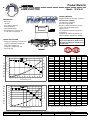
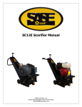
SASE
Corporate Office
26423 79th Ave South
Kent, WA 98032-7321
1.800.522.2606 (P)
1.877.762.0748 (F)
www.SASECompany.com
[email protected]
Congratulations on your decision to get the Power of SASE behind you! SASE is committed to excellence,
excellence in the quality of products we sell and excellence in service and support after the sale. It is important to us that your business continues to succeed and grow, and we know that the right products, service and support can have a great impact on your bottom line.
SASE has made great strides in the concrete preparation and polishing industry over the years. With a
40,000 square foot distribution and service facility in Seattle, a 22,000 square foot distribution and service
facility in Knoxville, and local sales and technical support representatives throughout the United States,
SASE is able to provide unsurpassed service and technical support for the contractor.
At SASE we engineer and manufacture our own equipment, which allows us to be in control of the quality
of the equipment we sell. SASE offers a complete line of concrete preparation and polishing equipment,
our newest introduction being our new line of PDG planetary diamond grinders, which is setting a new
standard for the concrete grinding and polishing industry. SASE is also the leader in diamond tooling technology.
We look forward to a long and prosperous partnership with you! Thank you again for choosing SASE.
You won’t regret having the Power of SASE behind your company!
Sincerely,
SASE Company, Inc.
Jim Weder
President
S A S E
I N D U S T R I A L
V A C U U M S
WARRANTY
SASE Company, Inc. warrants this equipment to operate within the limits of
our specification when properly used, properly operated, and properly
maintained. Various subsystems are warranted as follows:
All metal work excluding paint:
6 years
Limited to failure of structural due to
poor workmanship.
Vacuum Producer:
6 months
Limited to premature failure due to
poor workmanship by manufacturer.
Filters:
2 years (4000 hours)
Limited to premature failure due to
poor workmanship.
Any part proven defective in material and workmanship shall be duplicated
without charge F.O.B. your jobsite. This warranty excludes normal wear
and tear of parts or equipment, and especially excludes degradation from
normal abrasion of corrosion.
Please note! The vacuum producer requires unrestricted air flow! Running the
SASE Bull 300 “deadheaded” for more than a few minutes will overheat the
vacuum producer and void the warranty.
This warranty shall be void if the equipment has been altered or if any
attempt to repair this equipment has been made by persons, institutions or firms
not authorized by SASE Company, Inc. to make repairs.
SASE Company, Inc. will not be responsible for any costs of LABOR to remove
or re-install equipment, TOOLS, MATERIALS, INSURANCE, OVERHEAD
or any INCIDENTAL, SPECIAL, CONSEQUENTIAL or other expenses
which may be incurred by the purchaser in the execution of this warranty.
SASE Company, Inc. will NOT assume any responsibility under terms of
this warranty in parts or equipment which have not been paid for in full, or
where an account is outstanding for 60 days or more.
Please call 1-800-522-2606 with any questions!
S A S E
I N D U S T R I A L
1
V A C U U M S
Section
Bull 300
Series
Health and Safety
Recommendations
The Infor mation Contained In This Section
Can Help Prevent Serious Personal Injur y.
PLEASE READ THIS SECTION CAREFULLY
BEFORE OPERATING OR SERVICING THIS
EQUIPMENT.
T
his section outlines some of the health and safety issues that must
be acknowledged when operating or servicing your SASE industrial
vacuum cleaning system.
It is important that plant operators are made aware of the responsibility
incumbent on them to take all necessary precautions to ensure their health and
safety, and that plant authorities implement the procedures necessary toward this
end.
We strongly advise that you, the customer, add to, and tailor, these safety
recommendations to suit your own particular working and operating
environment.
Explosive Dust
Please contact us
if your process
changes so we
may help evaluate
your risk.
The operators of this equipment must always be aware of the physical and
chemical properties of the dust particles being collected. A surprising number of
dusts are flammable or prone to explosion when mixed with air as we find with a
filter receiver application.
Materials or processes presenting such hazards MUST be identified by the
customer.
S A S E
I N D U S T R I A L
V A C U U M S
The customer must also be alert to any changes in the dust material or process.
If a new process is introduced after the installation of the vacuum system which
changes the composition, quantity, or most especially the chemical type of
material being introduced into the vacuum system, this may greatly increase the
chance of explosion and fire.
If your process is to be changed, or if you have any concerns, we suggest you
contact us to see how we can assist you to ensure that the operation of your
SASE industrial vacuum cleaning system is as safe as possible.
Isolate Electrical Before Maintenance
Company specific
lockout and safety
procedures should
be inserted in this
section.
DO NOT ATTEMPT ANY MAINTENANCE WORK UNTIL
ALL ELECTRICAL GEAR HAS BEEN ISOLATED.
Isolate all electrical before removing any guards, covers or accessories before
beginning any maintenance or repair work.
Always lock out the main system blower disconnect before opening any
inspection door on any separator or filter receiver.
Before re-connecting the electrical supply, ensure that all guards, covers and
accessories are correctly replaced.
Implement Measures to Handle Respirable
Dust
Operators must be fitted with appropriate respirators and must wear protective
clothing if handling dust that may be irritating or even toxic.
We recommend that the MSDS’s for each of the dusts to be handled by the
vacuum system be included in this manual, and that specific measures to handle
problem materials be clearly identified in those sections of this manual where the
operator is exposed to these dusts; i.e. filter bag replacement, etc.
S A S E
I N D U S T R I A L
V A C U U M S
Use Suitable Electrical Warning Notices
Do NOT leave electrical gear live and unattended without a suitable warning
notice.
Distinctive warning notices must be provided for posting in a conspicuous
position to any piece of electrical equipment or machinery on which maintenance
is being carried out, and which, for any reason whatsoever, is liable to be left
unattended while in a live condition.
Use CAUTION When Using the Hoses
SASE vacuum systems use blowers that develop very high vacuum conditions
which can be dangerous if caution is not observed.
DO NOT PUT THE END OF THE HOSE AGAINST YOUR
SKIN OR CLOTHES OR THOSE OF OTHERS!
Remove the hose from the inlet valve to dislodge materials that plug the end of
tools.
S A S E
C O M P A N Y ,
I N C .
top of the filter housing by use of tie wraps and the bags must not be loose or
out of place.
NOTE: A loose or unsecured bag will allow product to pass
through the filter separator and will plug the in-line filter.
The filter bags should be shaken at least daily, preferably after each use. To
shake filter bags, simply shut off the vacuum and shake the filter assembly arm
swiftly back and forth. This rapid movement will dislodge particles on the inside
of the filter bag surfaces and drop them into the dust can.
NOTE: The unit must be OFF in order to shake the filters.
If the filters are to be replaced, please replace them ALL at once, or they will be a
constant source of frustration.
Filter Bag Maintenance
The following is a recommended program of preventative maintenance:
1. Check that the filters are seated properly and that they do not appear
to be leaking WEEKLY. There should be NO appreciable or
visible dust inside the filter housing.
2. Replace ALL the filters if wear points or holes are noticed.
3. If the secondary filter cartridge becomes plugged, check for holes or
leakage in the primary filter bags, or upgrade the primary filter
material to a more efficient type.
4. Replace the secondary filter cartridge when it becomes dirty.
Operators must be
outfitted with
appropriate
respirators and
must wear
protective clothing
if handling dust
that may be
irritating or toxic.
Removing Filter Bags
Access the filters by removing the vacuum producer section. To change the
filter bags, clip the plastic wrap on each bag tied on the filter shaker assembly
inside the tank at the top.
Squeeze the spring cuff at the bottom of the bag compressing the snap ring into a
“U” shape, and remove from the bag plate hole.
S A S E
C O M P A N Y ,
I N C .
Vacuum Seals
If you experience a “lack of suction”, almost certainly there is a leak in a seal
somewhere in the system. The following is a short list of common fail points:
1. Check all gasket seals. If air is leaking in through these seals, dust will
normally collect on the inside surface of the housing showing the exact
location of the leak. Sometimes, running your hands around the door
frame will allow you to locate the leak. Either way, replace the seals as
required.
2. Especially check the dust can gaskets. If they are torn or worn, please
replace them.
3. DO NOT over-tighten the lifting mechanism. Almost certainly that will
cause more problems than it fixes. The dust can flange need only
depress the gasket. The seal will form when the system is turned on.
Over-tightening the lifting mechanism will only lead to premature wear
of the gasket and will cause constant problems.
4. Check the hoses for cracks and leaks. A hose covered in duct tape is a
sure indicator that the hoses should be replaced.
Product Bulletin
LAMB ELECTRIC
Model: 121018-00
SPECIAL FEATURES
-
Suitable for 120v AC operation, 50/60 Hz
Speed control capability
UL component recognized
Provision for grounding
Brushless Switched Reluctance design
10 mm shaft and bearing system
Flat fan system
Fuse protection included on electronics
circuit board
- Aluminum fan end bracket designed to
dampen vibration and improve durability
DESCRIPTION
- One stage
- 120 volts
- 9.0" / 229 mm diameter
- Dual ball bearings
- Tangential discharge
- All aluminum die cast housings
used in motor construction
Please refer to SR Blower Application
Notes (listed below) for details on the
operation and wiring of our SR speed
control motor.
DESIGN APPLICATION
- Equipment operating in environments
requiring separation of working air
from motor ventilating air
- Designed to handle clean, dry,
filtered air only
TYPICAL MOTOR PERFORMANCE.*
80
Flow
250
60
200
50
150
40
30
100
20
50
10
0
2.000
1.750
1.500
1.250
1.125
1.000
0.875
0.750
0.625
0.500
0.375
0.250
0.000
0
Orifice Diameter (Inches)
120
2000
1800
Flow
100
1600
1400
80
1200
60
1000
800
40
600
400
20
200
Watts
RPM
(In)
Vac
Flow
Air
(In.H2O)
(CFM)
Watts
2.000
16.4
1758
20820
21.8
238.4
612
1.750
16.4
1750
20820
28.4
207.0
692
1.500
16.8
1771
21310
37.1
173.0
754
1.250
15.8
1654
22000
44.8
132.4
697
1.125
14.9
1600
22570
47.8
110.7
622
1.000
14.5
1488
22900
50.1
89.6
528
0.875
13.4
1410
23600
54.5
71.7
459
0.750
12.5
1317
24400
62.3
56.2
411
0.625
12.4
1293
25480
67.5
40.5
321
0.500
11.8
1223
26390
69.5
26.3
215
0.375
11.0
1161
26900
69.6
14.9
122
0.250
11.1
1158
27930
70.4
7.0
58
0.000
10.6
1110
28440
70.1
0.0
0
Orifice
Amps
Watts
RPM
(mm)
Air Flow--L/Sec.
D
A
T
A
Vac
Vacuum--MM H20
M
E
T
R
I
C
Amps
(Inches)
Air Flow--CFM
Vacuum--Inches H2O
D
A
T
A
Orifice
300
Vac
70
A
S
T
M
(At 120 volts, 60Hz, test data is corrected to standard conditions of 29.92 Hg, 68° F.)
(In)
Vac
Flow
Air
(mm H2O)
(L/Sec)
Watts
647
48.0
16.4
1754
20820
627
106.0
40.0
16.7
1765
21163
876
86.5
735
30.0
15.3
1624
22314
1180
56.9
656
23.0
13.7
1430
23425
1356
36.0
476
19.0
12.5
1317
24422
1585
26.4
409
16.0
12.4
1294
25437
1709
19.4
325
13.0
11.9
1230
26299
1760
13.1
226
10.0
11.1
1170
26824
1767
7.8
136
6.5
11.0
1158
27879
1787
3.5
61
0.0
10.6
1110
28440
1781
0.0
0
0
0
0.0
6.5
10.0
13.0 16.0 19.0 23.0
Orifice Diameter (mm)
30.0
40.0
48.0
Note: Metric performance data is calculated from the ASTM data above.
* Data represents performance of a typical motor sampled from a large production quantity. Individual motor data may vary due to normal manufacturing variances.
Test Specs: TBD
Minimum Sealed Vacuum: TBD
ORIFICE: 7/8"
Minimum Vacuum: TBD
Maximum Watts: TBD
PRODUCT BULLETIN
121018-00
DIMENSIONS
All switched reluctance motors are thermally protected using an auto-reset device.
(120v) AC Power Input
90v - 135v Nominal Operating Voltage
Manufactured under Patent nos. US5789893, TW81993, SG38957, ZA96/2766, US5760519, EP0702448B1, ZA95/7123 under license from
Switched Reluctance Drives Ltd. Other US and foreign patents pending. Copyright code 1998. All rights reserved.
IMPORTANT NOTES:
Pictorial and dimensional data are subject to change without notice. Contact factory for current revision levels.
WARNING
When using AMETEK/Lamb Electric bypass motors in machines that come in contact with foam, liquid (including water)
-
of other foreign substances, the machine must be designed and constructed to prevent those substances from reaching the fan system, motor housing
and electrical components. Lamb vacuum motors other than hazardous duty models should not be applied in machines that come in contact
with dry chemicals or other volatile materials. Failure to observe these precautions could cause flashing (depending on volatility) or electrical shock
which could result in property damage and severe bodily injury, including death in extreme cases. All applications incorporating Lamb motors should be
submitted to appropriate organizations or agencies for testing specifically related to the safety of your equipment.
Switched Reluctance Blower
Application Notes
Page 1
Lamb Electric Infin-A-Tek (SR) Blower User's Guide
The INFIN-A-TEK blower utilizes a switched reluctance (SR) brushless motor, which is commutated electronically. Similar to a brush type
series universal motor, the INFIN-A-TEK (SR) blower operates from AC line voltage (90v - 135v nominal voltage). However, the INFIN-ATEK (SR) blower features an integral electronic control module that rectifies the "AC line voltage" to obtain the DC voltage required to
power the motor.
The INFIN-A-TEK (SR) blower contains an imbedded microprocessor which controls the SR motor. This feature allows for the addition of
an electronic "SPEED CONTROL", which allows the user to remotely control the speed of the blower. Speed control is obtained by use of
a low voltage signal (provided by the customer) and can be in the form of either an AC, or DC signal (34V and 48V maximum
respectively). The signal voltage tells the motor when to turn on, and also at what speed to operate. It is important to note the SR motor
requires a minimum of 3.5V to start the motor, and reaches full speed at 12V. Our "SPEED CONTROL" will present a maximum 20
milliamp load to the control signal voltage. Please consult our wiring diagram listed below for specific wiring details.
Please review the diagram below carefully. The connection of the wires from the blower must
be in accord with this sketch for the unit to operate properly.
(120v) AC Power Input
90v - 135v Nominal Operating Voltage
Important Notes:
1. Motor "SPEED CONTROL" can be obtained by supplying either AC (34V maximum) or DC (48V maximum) voltage signal to
the motor control wires. The input signal should be applied to the Yellow #20 awg and Orange #20 awg control wires as shown in
the above diagram. Failure to limit the above AC and DC input voltages could result in controller damage.
2. A minimum of 3.5V input signal is required to start the operation of the blower, and maximum speed is reached at 12V.
All switched reluctance motors are thermally protected using an auto-reset device.
Switched Reluctance Blower
Application Notes Continued
Page 2
Lamb Electric Infin-A-Tek (SR) Blower User's Guide
DIAGRAM A:
TYPICAL TANGENTIAL EXHAUST
SR BLOWER INSTALLATION
NOTE: The customer's vent
cover must allow for a
minimum of 4.0 square
inches of cooling area to
provide adequate motor
cooling
NOTE: Motor mounting
must not restrict air inlet
ports on motor cover
DIAGRAM B:
TYPICAL PERIPHERAL EXHAUST
SR BLOWER INSTALLATION
NOTE: The customer's vent
cover must allow for a
minimum of 4.0 square
inches of cooling area to
provide adequate motor
cooling
NOTE: Motor mounting
must not restrict air inlet
ports on motor cover
Installation Notes / Recommendations:
The above diagrams (A & B) provide "typical" installation recommendations for the application of Infin-A-Tek (SR) tangential
exhaust and peripheral exhaust blower products. This information illistrates the required separation of "working / vacuum air" and
"cooling air" within the above product enclosure. The separation of "working / vacuum air" and "cooling air" is essential to
maintaining the extended life of the SR blower motors. Prolonged exposure of the motor's electronics to elevated temperatures, is
not recommended.
AMETEK/Lamb Electric Division
627 Lake Street
Kent, Ohio 44240 (U.S.A)
Tel: (330) 673-3451 Fax: (330) 673-8994
Revised: July, 2004
SASE BULL 300
27.00
BLOWER
28.38
SOUND PROOFING
FILTER
SHAKER
SILENCERS
SAFETY
FILTER
HEAVY
DUTY
FRAME
64.37
36.7 SF
PRIMARY
FILTER
3" OD
5"
SASE COMPANY, INC.
KENT, WA 98032 800-522-2606