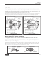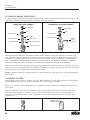
1
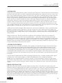
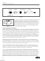
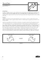
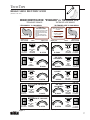
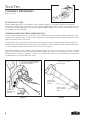
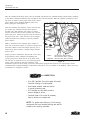
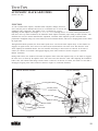
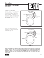
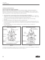
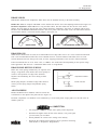
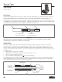
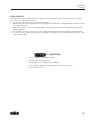
FOUNDATION
AIR BRAKES
Includes:
Foundation Air Brake
Hardware Kits
Camshafts/Camshaft
Repair Kits
Automatic Slack Adjusters
Air Brake Chambers
Air Wedge Brakes
Air Hose
MODULE ONE
TECH TIPS
FOUNDATION AIR BRAKE HARDWARE KITS
(Product Code 101)
FUNCTION
Air brake hardware kits are designed to provide all the components required to achieve maximum lining life, stopping
power, and stability of the foundation brake at each reline. Each hardware kit is designed for a specific application;
correct component identification is critical. Euclid Master Catalog 100 provides critical dimensions of all components
for identification purposes. Wall charts are also provided to aid in brake shoe identification.
TYPE
In the aftermarket, air brake hardware kits are available in various quality levels and number of components in each kit.
The end user should pay attention to these differences to assure that he is purchasing a quality kit from a reputable
manufacturer. The old saying, "You get what you pay for," certainly applies to brake kits.
Euclid air brake hardware kits are available with a variety of components, from minor kits which range from some
containing only high wear components, to the major kits which repair one complete wheel. These major repair kits are
Euclid's MEGA PLUS Maximum Life, MEGA Premium Quality, and STOPMATE Standard Quality brake kits. Euclid
MEGA PLUS kits are complete kits designed for today's "extended service" applications and provide for maximum life
by using heavy-duty shot-peened return springs, dimpled anchor pin bushings and antiseize lubricant. Euclid MEGA
heavy-duty brake kits include all the needed components including: anchor pins, rollers, heavy duty return springs,
spring and roller retainers, washers, lock rings, and bushings. Euclid STOPMATE brake kits also include all the
components needed to repair one complete wheel, but offer a standard quality level rather than a premium quality
level with added durability. In this issue of Tech Tips we will highlight most of these components, their wear points,
and types available.
GENERAL INSPECTION RECOMMENDATIONS
As foundation brake hardware wears, brake shoe and lining wear is affected. Brake lining wear patterns are a good place
to start troubleshooting foundation brake hardware problems. Euclid supplies a Wall Chart (A-504) and a Service
Bulletin (B-20) which describes possible causes and solutions to the most common brake lining wear problems.
BRAKE SHOES
Brake shoes need to be inspected for anchor pin connection wear (See Figure 1), roller connection wear, web
straightness (See Figure 2), stretch (See Figure 3), and table flatness. Several styles of tools to check these wear points
are available individually or as one unit such as Euclid’s E-3863 Brake Shoe Gauge. Most brake shoe gauges are "GO/
NO-GO" style and reject only those brake shoes which are worn beyond the minimum allowable dimensions. To achieve
the best brake performance, old worn shoes must be discarded and replaced with new lined shoes.
Figure 1
Figure 2
Euclid E-3863 Brake Shoe Gauge
2
weindex.info
Figure 3
TECH TIPS
Foundation Air Brake Hardware Kits
ANCHOR PINS
Anchor pins position and maintain the position of the brake shoes. Brake force is transferred from the shoes through the
anchor pin to the brake spider. As a result of normal movement and brake force, anchor pins will wear. As they wear,
they no longer maintain the proper position of the brake shoes. This allows for unmatched lining to drum contact and
inferior braking. Rockwell's designed brakes, "P" & "Q", are manufactured with two replaceable anchor pins, which,
because of wear, must be replaced at each brake reline. Euclid supplies all replaceable pins with a precision ground
finish to provide the smoothest possible wear surface, while other manufacturers often use a standard, ungrounded
finish on their anchor pins. Eaton’s non-replaceable single anchor pin must be closely inspected for wear and
roughness. Make sure Eaton anchor pins are smooth and free of irregularities. Eaton’s specifications allow for up to
.031" of wear before the entire brake spider must be replaced. This .031" is the maximum wear limit however, and
wear in smaller amounts may also cause brake shoes to be positioned incorrectly and create unusual wear on the brake
lining. Roughness on anchor pins can cause faster wear on pins, bushings, and shoes.
Anchor pin heat treatment and depth of heat treatment also varies between manufacturers. Today’s non-asbestos lining
materials are lasting up to 50% longer than in years past, causing more wear on anchor pins. Euclid supplies only
anchor pins that have been hardened to OE specifications, ensuring a consistent wear surface is maintained through the
life of the brake lining. A thinner surface may be worn through at an interval between relines causing unstable and
inferior braking.
Plating of anchor pins is the most obvious part to examine for wear when doing a brake reline job. Platings are
available in black oxide, zinc, and in many Euclid MEGA Kits — hard chrome. All these platings provide good
corrosion resistance before any brake force is applied to them. Hard chrome anchor pins are available in many Euclid
kits which have severe service applications and provide the ultimate in wear resistance. NOTE: Anti-seize lubricant
should be used in the assembly of anchor pins/bushings, regardless which plating and material is being used, in order
to insure smooth rolling action and prevent corrosion.
ANCHOR PIN BUSHINGS
As anchor pins wear, so do anchor pin bushings. These bushings are included in all complete wheel brake kits where
they are used and need to be replaced. Proper tools should be used to remove and install these bushings to avoid
deforming them during installation. Inspect the anchor pin bushing hole in the brake spider for wear. If the hole is
worn and cannot provide an adequate press fit to the bushing, the spider must be replaced. Special tools, such as
E-3864B Brake Spider Alignment Tool, are also available to check the alignment of the anchor pin holes in the spider.
If the spider holes do not meet specifications, the brake shoe will not be held square to the drum and the spider must
be replaced.
Corrosion between standard mild steel anchor pin bushings and anchor pins is a common complaint. Euclid supplies
a stainless steel version of these bushings in its MEGA and MEGA PLUS kits to eliminate this problem.
NOTE: Anti-seize compound should be used in the assembly of anchor pins/bushings, regardless of which plating
and material is being used in order to insure smooth rolling action and prevent corrosion. Euclid's MEGA PLUS kits
include a corrosion resistant non-magnetic stainless bushings with a dimpled inner surface to hold antiseize lubricant
in place.
BRAKE SHOE ROLLERS
Brake shoe rollers transfer the force from the camshaft to the brake shoes. As the rollers move up the ramps of the
camshaft, the brakes are applied. Brake shoe rollers are manufactured in two major types: smooth and knurled. Knurled
rollers, like the diamond-knurled designed rollers supplied by Euclid, create a positive rolling action and when
installed properly, eliminate flat spot problems on the head of the camshaft. Although knurled rollers may roll a
pattern in the head of the camshaft, this pattern does not wear the camshaft. By staying in the same pattern it is proof
that the roller is rolling much like gears in mesh and not sliding because sliding wears the camshaft. Some rollers are
held in place during assembly by wire roller retainers. These retainers may be installed incorrectly and cause the best
knurled roller not to turn. The most commonly mis-installed roller retainer is the E-3007A.
3
weindex.info
TECH TIPS
Foundation Air Brake Hardware Kits
Lube here
Lube here
Do not lube here
Lube here
Do not lube here
Figure 4
Figure 5
To aid the rollers in turning, only the pins must be lubricated (See Figure 4). DO
NOT APPLY LUBRICATION TO THE ROLLING SURFACE OR HEAD OF
CAMSHAFT. If lubrication is applied to either of these rolling surfaces, the
rollers will tend to slide and not roll. This sliding action will create flat spots on
the face of the roller and cause wear on the camshaft. Flat spots on rollers can
cause brake adjustment to make very wide lining to drum clearance swings as
these flat spots roll around (See Figure 5). Even without lubrication smooth
rollers are still susceptible to flat spots.
BRAKE SHOE RETURN SPRINGS
Brake shoe return springs serve two important functions: 1) to prevent brake shoes from dragging on the brake drum;
and 2) to maintain tight contact between the brake shoes, rollers, and the camshaft. These springs are also a major
factor in release timing of foundation air brakes. Many uneven wear problems between wheels on a vehicle can be
attributed to weak return springs. Brake return springs are manufactured for the heavy-duty market in different wire
types, often designated as standard or heavy-duty. These wire types are not physically identifiable without specialized
lab testing. Many end-users relate wire diameter to the classification of the return spring, (i.e., small diameter =
standard, large diameter = heavy-duty). Although wire diameter is a factor in spring strength, it is not the only factor.
Color coding between manufacturers is also something that will not indicate the strength of a return spring. Because
there is no real in-field test that can determine the strength of a return spring, end-users must rely on their quality
manufacturers for new springs and replace all return springs at each reline.
Brake shoe return springs, when nicked or marked, will most often fail at that mark. Care should be taken when
installing new return springs not to nick them. A screwdriver between the coils must never be used to install springs.
During manufacturing there is a slight possibility of a mark or imperfection on the spring. For this reason Euclid has
always exceeded OEM spring specifications by shot-peening its MEGA and MEGA PLUS heavy-duty return spring to
remove any stress that otherwise could cause the spring to fail or brakes to drag.
As we have examined each of the above components of brake shoe repair kits, it is clear that each and every part
experiences wear through the life of the brake lining. Although this wear may seem small at a visual inspection,
combined, it can cause very severe brake wear and performance problems. To insure maximum brake life and peak
performance, all foundation brake hardware components must be replaced at each brake reline.
For over 50 years, Euclid has supplied brake components that are manufactured under the strictest quality controls in
the industry. MEGA heavy-duty brake shoe repair kits include only premium quality components: stainless steel
bushings, diamond-knurled rollers, and shot-peened heavy-duty return springs -- the best in the industry, exceeding
OEM specifications. MEGA PLUS kits include the same high quality components of MEGA kits but add 100 lb. shotpeened return springs, dimpled anchor pin bushings, and antiseize lubricant. For the price-sensitive market segment,
Euclid offers the STOPMATE standard quality brake shoe repair kit which features: zinc clear chromate plated and
hardened anchor pins which resist corrosion, diamond-knurled rollers and standard or heavy-duty return springs.
STOPMATE kits meet OEM specifications while Euclid MEGA and MEGA PLUS kits exceed OEM specifications.
4
weindex.info
TECH TIPS
Foundation Air Brake Hardware Kits
vs. COMPETITION
• Euclid brake kits meet or exceed OEM specifications in order to provide the vehicle owner longer
life and improved performance on his investment
in brake hardware.
• A higher quality brake kit will cost more initially,
but will pay off in the long run with less wear on
brake-lining and drums.
• The popularity of automatic slack adjusters and
non-asbestos brake lining have increased the stress
on foundation brake hardware. Thus, more
heavy-duty, high quality parts such as Euclid’s are
required to meet today’s stress loads.
• Euclid offers 80 cataloged brake kits covering a
broad range of heavy-duty truck and trailer air
brake applications.
• Euclid offers the finest and most detailed catalog
information on air brake kits. A photograph and
list of components is shown for each kit to ease in
identification.
5
weindex.info
TECH TIPS
CAMSHAFTS
(Product Code 103)
FUNCTION
Air Brake Camshafts are part of a series of fulcrums and levers that transfer brake application force through the brake
system. Force from the air brake chamber pushes the arm of the slack adjuster. The slack adjuster, mated to the
Camshaft by splines, rotates the camshaft. The center of the camshaft becomes the fulcrum. When the "S" head of the
Camshaft rotates, it delivers the brake force to the roller ends of the brake shoes and pushes them into contact with the
brake drum.
TYPES
Camshafts are designed for specific brake applications. They are available in a variety of lengths, bushing journal
diameters, head sizes, number of splines and spline diameters. Camshaft lengths are determined by the location of the
air brake chamber.
Head sizes are determined by the type and size of the brake. A 15" diameter steering axle cam commonly uses a small
"flat" type camshaft head. The 12 1/4" diameter trailer brakes use small, but deeper, "S" shaped camshaft heads. The
16 1/2" and 18" steering, drive or trailer axle brakes use large, "S" shaped camshaft heads on standard applications. Late
model camshaft heads have evolved into the "extended life" design. These new heads for 16 1/2" application utilize
deeper pockets for use with the thicker brake blocks while using standards drums. Care must be taken when identifying
these two camshaft types (See Figure 7). Standard head camshafts cannot be used when using "extended life" brake
shoes. When using "extended life" camshafts, standard or "extended life" brake block can be used. Always use the
same style camshaft on both sides of an axle to promote a balanced brake condition. As shown in Figure 6, the
direction the camshaft head rotates to apply the brakes determines if the camshaft is "right hand" or "left hand". The
side of the vehicle the Camshaft is located on has no bearing on whether the camshaft is "right hand" or "left hand".
BRAKE CAMSHAFT
LEFT HAND
BRAKE CAMSHAFT
RIGHT HAND
View From
Head End
Figure 6
6
TECH TIPS
BRAKE SHOE IDENTIFICATION
(Product Code 103)
BRAKE IDENTIFICATION: "STANDARD" vs. "EXTENDED LIFE"
"STANDARD" BRAKES
"EXTENDED LIFE" BRAKES
"STANDARD" S-CAM HEAD
13/8"
HOW TO
USE THIS CHART
Compare Brake Shoe Profiles
Compare Table End Views
Compare Brake Block Drill
Patterns
Determine Which Type of
Camshaft Each Brake Shoe
Uses
•
•
•
•
(Left hand shown)
BRAKE BLOCK
DRILL PATERN
TABLE
BRAKE TYPE
FMSI 4311J
28 Holes
Thick
10-8 Rivets
3/4"
EATON
anchor end
view
Use "std."
OR
"ext. life"
camshaft
roller end
view
32 Holes
Thick
10-8 Rivets
3/4"
32 Holes
Thick
10-8 Rivets
32 Holes
Thick
10-8 Rivets
3/ 4"
E-3920
Figure 7
BRAKE BLOCK
DRILL PATTERN
FMSI 4709
Use
"ext. life"
camshaft
E-5480
EATON TOP SPEC
"ES" FOR
FRUEHAUF
11/16"
E-8922
E-5503
28 Holes
Thick
10-9 Rivets
13/16"
FMSI 4707
Use
"ext. life"
camshaft
EATON TOP SPEC
"ES" FOR
ROCKWELL
28 Holes
Thick
10-9 Rivets
7/8"
FMSI 4708
roller end
view
1"
11/4"
1"
1"
E-6075
E-8924
Use "std."
OR
"ext. life"
camshaft
11/4"
28 Holes
Thick
10-9 Rivets
13/16"
FMSI 4701
SPICER "XL"
roller end
view
11/4"
1"
E-2778
Use
"std."
camshaft
roller end
view
E-2778
1"
FMSI 4708
ROCKWELL
"Q PLUS"
1"
SPICER
"FAST CHANGE"
28 Holes
7/8" Thick
10-9 Rivets
roller end
view
11/4"
ROCKWELL "Q"
FOR FRUEHAUF
Use "std."
OR
"ext. life"
camshaft
TABLE
EATON "ES"
59/64"
roller end
11/4"
view
Use "std."
OR
1"
"ext. life"
camshaft
roller end
view
BRAKE TYPE
11/4"
ROCKWELL "Q"
FMSI 4515E
(Left hand shown)
Fruehauf brakes use ONLY
"standard" camshafts.
11/16"
roller end
view
Use "std."
OR
"ext. life"
camshaft
11/8"
Most "extended life" brakes
use ONLY "extended
life" camshafts.
E-1778
Use
"std."
camshaft
FMSI 4515E
32 Holes
3/4" Thick
10-8 Rivets
11/4"
59/64"
FMSI 4515E
3/ 4"
"Standard" brakes use "standard" OR "extended life"
camshafts.
anchor end
view
FRUEHAUF "XEM"
FMSI 4515E
"EXTENDED LIFE" S-CAM HEAD
E-2778
Use
"ext. life"
camshaft
24 Holes
Thick
10-9 Rivets
7/ 8"
Full color reprints of this Chart (A-505) are available.
7
TECH TIPS
CAMSHAFT REPAIR KITS
(Product Code 104)
FUNCTION & TYPES
Euclid Camshaft Repair Kits are designed to restore camshaft operation to its original equipment specifications,
providing the camshaft itself is not excessively worn. Euclid Camshaft Repair Kits come in many configurations to fit
a wide variety of brake applications. They contain enough camshaft bushings, seals, washers and lock rings to service
one complete axle (two camshafts).
GENERAL INSPECTION RECOMMENDATIONS
At each vehicle lubrication interval, any missing or loose camshaft lock rings and washers should be replaced. On selfcontained tractor brakes, make sure that the chassis lubrication is not leaking between the camshaft tube and the brake
spider. Replace the gasket if this occurs.
At each brake reline, certain inspection procedures must be performed on the camshafts and their related components.
Camshaft radial movement should be checked with a dial indicator. If radial movement exceeds .020" for Eaton brakes
or .030" for Rockwell brakes, the camshaft must be removed (See Figure 8).
Inspect the camshafts for wear, roughness, and/or deformed splines (See Figure 9), and replace as necessary. A knurled
pattern on the camshaft "S" head is an indication that knurled brake shoe rollers were rolling properly on the "S" head.
Smooth brake shoe rollers have a tendency to slide on "S" heads and cause them to wear. For this reason, Euclid always
recommends the use of knurled brake shoe rollers.
If more than .020" (Eaton Brakes) or
.030" (Rockwell Brakes), replace
bushings then recheck!
Check for wear, cracks
and flat spots
Check for wear,
roughness and
corrosion
Check for cracks,
wear or deformed
splines
MOVE
Note maximum
deflection
Figure 8
8
Figure 9
TECH TIPS
Camshaft Repair Kits
If camshaft bushings have been worn at any point, check the brake spider or camshaft support bracket before installing
new bushings and seals. Wear in the spider or camshaft support bracket affect the fit of the bushings and help create
excessive radial movement. Camshaft bushings and seals should be installed using the proper installation tools. For
1 1/2" I.D. bushings and seals, use Euclid installation tool, E-1250; for 1 5/8" I.D., use part number E-2739.
When using self-aligning camshaft support brackets and bushings on trailer axles, do not completely torque the support
bracket retaining bolts until the camshaft is installed through the bushing. After the camshaft is installed and the bolts
properly torqued, the camshaft must turn freely by hand. If not, camshaft seals are commonly installed incorrectly. This
can cause excessive grease build up on the camshaft head and brake shoe rollers. The correct installation of camshaft
seals and "O" rings is shown in Figures 10 and 11.
SEAL INSTALLATION INTO A CAMSHAFT BRACKET
SEAL AND "O" RING INSTALLATION INTO A
BRAKE SPIDER
SEAL
"O" RING
SEAL
LIP
SEAL
LIP
CAMSHAFT
BRACKET
INBOARD
SPIDER
OUTBOARD
Figure 10
Figure 11
9
TECH TIPS
Camshaft Repair Kits
Place the camshaft head thrust washer onto the camshaft and lubricate the camshaft bushing journals before installing
it. This makes camshaft installation easier and protects the seals from damage. When the camshaft is installed, it must
turn freely by hand to insure proper brake release. Place a
spacer washer on the installed camshaft's spline end
before putting the slack adjuster on.
After the camshaft, slack adjuster, washers and lock ring
are in place, the camshaft axial movement must be
checked with a dial indicator (See Figure 12). Eaton
specifies axial movement be not less than .005" and not
greater than .045". Rockwell specifies axial movement be
not greater than .060". Axial movement can be brought
within specifications by adding or removing camshaft
spacer washers.
Note: A minimum of one camshaft spacer washer on
either side of the slack adjuster is required. If proper axial
movement cannot be achieved without removing one or
both of these spacer washers, a slightly longer camshaft
must be used.
MOVE
Note maximum
deflection
Proper preventive maintenance and periodic service must
Eaton No less than .005" (13mm)
be performed to insure camshafts and bushings will
Not more than .045" (1.14mm)
Rockwell - Not more than .060" (1.52mm)
provide good service during the life of the brake reline.
The intervals in which this service is performed depends
Figure 12
on the vehicle application and road conditions. Each
maintenance supervisor must design a preventive maintenance program that meets his own requirements. Euclid
recommends that camshaft bushings be lubricated a minimum of every six months for on-highway vehicles and every
four months for off-highway vehicles.
vs. COMPETITION
• Over 400 Camshafts. One of the largest "all-makes"
Camshaft offerings in the aftermarket.
• Heat-treated camshaft heads and splines
to prevent premature wear.
• All Camshafts are individually boxed to
prevent damage to splines.
• Camshaft Repair Kits contain all necessary
parts to rebush one complete axle.
NOTE: For greater brake efficiency, Euclid strongly
recommends that new camshaft bushings and seals be
installed when replacing camshafts.
10
TECH TIPS
AUTOMATIC SLACK ADJUSTERS
(Product Code 108)
FUNCTION
As with a manual slack adjuster, Automatic Slack Adjusters multiply the linear
force exerted by the air chamber and convert it to rotational force to activate the
foundation brake components. The chamber force is multiplied by a factor
depending on slack adjuster arm length, (i.e., 5 1/2", 6", 6 1/2"). Through the use of a fixed control point (bracket or
link) and a one-way clutch mechanism, the Automatic Slack Adjuster maintains proper lining to drum clearance. This
eliminates the need for constant manual brake adjustment. Automatic Slack Adjusters provide consistent brake
performance throughout lining life, better balance between individual brakes, and assist in keeping brake stroke within
the legal limits.
Through normal brake operation, the fixed control point moves a rack in the slack adjuster body. As the clutches are
engaged, on regular release, the worm screw is turned by the clutch and rack. The worm screw then turns the worm
wheel adjusting the foundation brakes. This will continue until lining to drum contact is achieved. At the time of
contact, the clutch to worm shaft is disengaged stopping worm wheel rotation as shown in Figure 13 (External
Bracket Actuation).
During brake release, the actuation rod rotates the adjuster wheel in the slack adjuster body. As the clutch is engaged,
the worm screw is turned by the adjuster wheel. The worm screw then turns the worm wheel adjusting the foundation
brakes. This will continue until lining to drum contact is achieved. At the time of contact, the clutch to worm shaft is
disengaged, stopping worm wheel rotation as shown in Figure 14 (Link Rod Actuation).
External Bracket Actuation
Link Rod Activation
Housing (Slack Body)
One Way Clutch
Components
Worm Gear
Return Springs
Worm Wheel
Rack
Control Plate
Figure 13
Figure 14
11
TECH TIPS
Automatic Slack Adjusters
ADJUSTING SENSING METHODS
1) Stroke Sensing
In sensing push rod stroke, several variables come into play. Push rod stroke becomes longer when any one or a
combination of the following are present: camshaft bushing wear, air chamber bracket deflection, or camshaft twist.
Once a longer stroke is sensed, the adjusting mechanism in the slack is activated, reducing the lining to drum clearance.
There is a possibility that with wear, push rod stroke could become longer than the legal limits while lining to drum
clearance is correct. In a stroke sensing Automatic Slack Adjuster, this stroke activates the adjusting mechanism, further
reducing lining to drum clearance and over adjusting the brake.
2) Clearance Sensing
The majority of Automatic Slack Adjusters produced today have lining to drum clearance sensing as the activation
method. Clearance sensing slacks employ a one-way clutch and load sensing mechanism which engages only until
brake application torque rises rapidly as brake shoes come into contact with drum. Push rod stroke and its
characteristic wear points are less of a factor in operating clearance sensing Automatic Slacks.
GENERAL INSPECTION RECOMMENDATIONS
An Automatic Slack Adjuster should never be manually adjusted while in service. The only time it should be manually
adjusted is during installation or reline. If manually adjusted frequently, the internal clutch life can be shortened.
Automatic Slack Adjusters should be lubricated at all routine vehicle chassis lubrications: 25,000 miles, or three
months, whichever occurs first. Some Automatic Slack Adjusters require the use of special lubricant to maintain
warranty. Euclid Automatic Slack Adjusters require no special lubricant.
Check all control arm brackets, external links and/or external boots for damage. These are the most vulnerable areas
that can cause improper operation of the adjusting mechanism resulting in Slack Adjuster failure.
The true test of an Automatic Slack Adjuster is "Does it maintain a proper shoe to drum clearance?" In a new
installation the Automatic Slack Adjuster should automatically maintain stroke as listed below. If correct on initial
installation, then during the brake lining life, the Automatic Slack Adjuster should maintain this stroke. The Automatic
Slack Adjuster cannot be operated as a manual adjuster. If, on a new installation, proper stroke cannot be obtained;
closely inspect the foundation brake for problems such as worn bushings, worn S-cam surfaces, flat spotted rollers, etc.
Air Chamber Size/Type
Desired Stroke
Type
Type
Type
Type
1 1/4" to 2" stroke
1 1/4" to 2" stroke
1" to 1 3/4" stroke
3/4" to 1 1/2" stroke
30 Air Chamber
24 Long Stroke
20-24 Air Chamber
9-12 Air Chamber
}
with
80 to 90 psi
Service Brake
Application
The air chamber push rod stroke can be difficult to measure properly. With a tape measure, measure the movement of
the push rod from the completely released position to the applied position (80 to 90 psi). This movement can also be
measured by marking the push rod where it exits the air chamber (brake released), then apply the brake and measure the
distance from the mark to the face of the air chamber.
The control arm location or clevis position should be checked if the brakes have been running tight or the push rod
stroke measurement is less than 1 1/4" on the rear axle or 3/4" on the steer axle.
If the stroke changes after a proper initial installation, foundation brake components should be checked before
replacing Automatic Slack Adjusters. Look for worn camshaft bushing, worn camshaft, weak or broken return springs,
etc. These components and their proper inspection and maintenance procedures can be seen in Euclid’s training video
"Air Foundation Brakes: The Hidden Challenge" (VIDEO-1).
Euclid offers two Automatic Slack Adjusters: Euclid/Haldex and Crewson Brunner. The features, benefits and proper
operation of each is listed on the following pages.
12
TECH TIPS
Automatic Slack Adjusters
EUCLID/HALDEX
Features
Unhanded design
Benefits & Advantages
Euclid/Haldex Automatic Slack Adjusters fit both left or right hand
applications, except for offsets which are available in 5/8" and 1 l/2" models.
Thus, greater product coverage results with fewer part numbers.
Available for 12 1/4" brakes
Euclid/Haldex Automatic Slack Adjusters are available for most 12 1/4"
brake applications.
Quicker to install
Euclid/Haldex uses existing clevis connection. Since clevis change is not
required, retrofit installation time can be cut in half.
Sealed to prevent contamination
Euclid/Haldex uses a fixed control arm with a totally sealed body. With no
external boots, contamination failure is eliminated.
Easy manual adjustment
Euclid/Haldex Automatic Slacks require no special procedure for deadjustment. Euclid/Haldex can be manually adjusted and de-adjusted at
reline or installation, the same as manual slack adjusters.
Unmatched warranty
The Euclid/Haldex warranty has been extended to 6 years /1,000,000 miles
for on-highway vehicles.
Reliable one-way clutch converting the linear motion of
the rack to rotary motion
Bearing made of free-cutting steel and
tenifer treated, give a minimum of friction.
Bushing made of hardened steel.
Housing cast in nodular iron and tenifer treated to give
a low coefficient of friction and high water resistance
The Hexagon on the end of the
worm screw makes installation
and change of linings easy
Arrow showing the direction of operation
Unique assymetrical tooth profile gives high
strength
Enclosed rack, sintered to a high standard of
density and hardness, transferring the movement of the stroke to the adjusting mechanism
Strong coil spring guarantees a constant
axial pressure of the worm screw
Recess in the control disc corresponding
to the desired clearance between brake
lining and brake drum
Rivets lock screw covers in the desired position
Three O-rings protect against dirt, water, etc.
Gasket between control unit and housing
Worm gear of specially treated high grade steel
Control arm for fixing the adjuster to
the anchor bracket (fixpoint)
Figure 15
OPERATION (See Figure 15)
Upon brake application, the slack adjuster rotates and moves the shoes into contact with the drum. The clearance notch
corresponds to the normal lining-to-drum clearance. As the brake application continues, the rack moves upwards and
rotates the one-way clutch which overrides in this direction. As the brake torque increases, the coil spring load is
overcome and the wormshaft is displaced axially, releasing the cone clutch.
When the brake begins its return stroke, the coil spring load returns to normal and the cone clutch is again engaged.
The rack is pulled back to its original position in the notch, and any additional travel brought about by lining wear
causes the rack to turn the locked one-way clutch and rotates the wormshaft through the locked cone clutch. The
wormshaft then rotates the wormwheel and camshaft, adjusting the brakes.
13
TECH TIPS
Automatic Slack Adjusters
CREWSON BRUNNER
AUTO SLACK SMART — MANUAL SLACK EASY
Features
Benefits & Advantages
Clearance AND load sensing
Less likely to overadjust than stroke or clearance-only sensing
Link rod actuation
No external mounting brackets that can be damaged, easier installation
Adjusts on brake return
Works with air chamber, shoe return springs, and brake components; not
against them - provides more consistent adjustment. This is important on
"new" long life brake designs.
Easy manual adjustment
Does not require component disassembly or cause excessive component wear
Extra grease sealing provisions
High integrity seals with built-in backup designs
Minimal part numbers for total
product coverage
Reduces inventory cost complexity. Fewer part numbers than automatic
slack adjusters with external mounting brackets or stroke-sensing adjusting.
Patented - Hands Free
Installation Guide
Quickset and most foolproof installation method (Figure 16)
Outstanding Warranty
Four (4) years or 400,000 miles, whichever occurs first, for on-highway trucks
tractors and trailers
Clevis control actuation reduces part
number inventories and speeds
installation.
Specially designed worm
and gear for extended life
Heavy-duty coil spring for
consistent gear set
preload
Housing made from
modular cast iron or
heat-treated forging
depending on part
number
Hexagon
shaft has
low rotational
torque for easy
installation
Clearing-sensing
clutch virtually
eliminates
unwanted brake
adjustment
All internal components
made from high strength,
hardened alloy steel
Figure 16
All sealing points
designed with back up
protection
Figure 17
Operation (Figure 17)
As the brakes are applied, the Slack Adjuster’s rotation moves the shoe and linings into contact with the brake drum.
This movement also lifts the actuation rod through a pre-set, free travel dimension that is the normal lining to drum
running clearance. Continuing the brake application rotates a one-way clutch in its overriding mode, and at the same
time causes the large coil spring to deflect at a specific force. This spring deflection allows the worm to move axially,
which releases the drive clutch and prevents unwanted brake adjustment from occurring.
As the brakes are released, the large coil spring resumes its original load and position, which allows the drive clutch to
re-engage. Simultaneous to drive clutch re-engagement, if any lining wear has occurred, the actuation rod rotates the
one way adjusting clutch an amount proportional to the lining wear. This motion rotates the worm, worm wheel, and
S-cam shaft, resulting in adjustment of the brakes.
14
TECH TIPS
AIR BRAKE CHAMBERS
(Product Code 131)
THE BRAKE CHAMBER
The Brake Chamber converts compressed air
into mechanical energy. This conversion is
accomplished by supplying compressed air
against a diaphragm. The diaphragm then
pushes against a paddle with an attached push
rod and Clevis. The force of compressed air
is now converted into mechanical braking
force (See Figure 18).
BRAKE APPLIED
Diaphragm
Return Spring Compressed
Compressed
Air In
Camshaft
Rotation
Figure 18
Braking force is discontinued when the
compressed air is exhausted from the Brake
Chamber (See Figure 19).
BRAKE UNAPPLIED
Diaphragm
Return Spring Extended
Compressed
Air Exhausted
Vent
Camshaft
Rotation
Figure 19
The Brake described above is a service brake chamber (See Figure 18 & 19). The combination brake chamber is
another type of chamber. The combination chamber combines a parking brake piggybacked on a service brake (See
Figure 20). The parking brake uses a very powerful compression spring to apply the brakes. Pressurized air against
the diaphragm and plate is used to compress the spring. WARNING: Failure to comply with all instructions for
mechanical release may result in the forceful release of the spring and cause death, severe personal injury and/or
property damage.
15
TECH TIPS
Air Brake Chambers
GENERAL INSTRUCTIONS
FOR SEALED TYPE SPRING BRAKES
There are two basic areas of failure related to service and combination chambers: Mechanical and pneumatic.
Both types of failures require the spring brake to be repaired or replaced. WARNING: Failure to comply with all
instructions for mechanical release of the spring may cause death, severe personal injury and/or property damage. To
replace the parking side of a brake chamber follow these general instructions:
1.
2.
3.
4.
5.
6.
Always block wheels to prevent vehicle rollaway when replacing spring brake diaphragms.
If spring brake shows structural damage DO NOT cage the spring and DO NOT attempt to service it. Replace the
complete unit. To prevent severe personal injury when removing an uncaged spring brake from a vehicle, cut the
service push rod with an acetylene cutting torch, making sure to relieve all force on it.
Never strike any part of the spring brake with a hammer or any other heavy object; structural damage
may result.
Do not drop spring brake, as the compression spring may forcefully release.
If air pressure is used to aid in the caging process, do not tighten release tool nut more than finger tight. The air
pressure in the emergency chamber must always be exhausted after the spring has been mechanically caged prior
to any disassembly.
On a sealed spring brake, the emergency diaphragm cannot be replaced (See Figure 20). Replace the
complete piggyback unit.
SERVICE BRAKE RELEASED
SERVICE BRAKE RELEASED
Service Return
Spring Extended
Service Return
Spring Compressed
Service Push Rod
Parking
Push Rod
Air Pressure
No Air
Pressure
Diaphragm
Plate
Compression
Spring
Compressed
Parking Return
Spring
Compression
Spring Extended
PARKING BRAKE NOT APPLIED
PARKING BRAKE APPLIED
Figure 20
Figure 21
The spring extends and applies the brakes when air is exhausted from the emergency brake diaphragm. The spring will
also extend if air pressure on the trailer drops below 60 psi. (See Figure 21).
16
TECH TIPS
Air Brake Chambers
MECHANICAL RELEASE OF SPRING BRAKE -ALL TYPES
DANGER: Do not attempt to mechanically release (cage) the spring when spring brake shows structural
damage and/or when safety ears have been removed. Caging the spring or disassembly of the chamber
may result in the forceful release of the spring chamber and its contents which could cause death, severe
personal injury and/or property damage. Remove complete spring brake and replace with new unit.
* NOTICE: There are no safety ears or clamp on a Sealed Type Brake.
1. Remove dust plug from release tool keyhole in center of spring chamber. (Figure 22)
2. Remove release tool assembly from side pocket of adapter. (Figure 22)
3. Insert release stud through keyhole in chamber into the pressure plate. (Figure 23)
4. Turn release stud 1/4 turn clockwise. (Figure 23)
5. Pull on release stud to ensure stud crosspin is properly seated in the pressure plate. (Figure 23)
6. Assemble the release stud washer and nut on release stud finger tight. (Figure 24)
DANGER: The below listed instructions (step 7) only apply when spring brake is not pressurized. If air
pressure is used to compress the spring, do not tighten release stud nut more than finger tight. Torquing the
nut can cause pressure plate damage resulting in sudden release of the spring causing death or severe
personal injury.
7.
To cage the compression spring, tighten release stud nut with hand wrench (DO NOT USE IMPACT WRENCH)
and make certain the push rod is retracting. (Figure 24)
a.
DO NOT OVER TORQUE RELEASE STUD ASSEMBLY:
DANGER: Over torquing the nut can cause pressure plate damage.
S-Cam type 35 ft. lb. (47 Nm Maximum)
Wedge type 20 ft. lb. (27 Nm Maximum)
b.
To ensure that the compression spring is fully caged, the stud length beyond the nut (see "X" Figure 24)
should measure:
ALUMINUM CHAMBER TYPES
36" Chamber - 3 3/8" Min.
16" Chamber - 3 1/8" Min.
30" Chamber - 2 3/4" Min.
12" Chamber - 2 3/8" Min.
24" Chamber - 2 13/16" Min.
SEALED AND STEEL CHAMBER TYPES
30" Chamber- 2 7/8" Min.
24" Chamber - 2 29/32" Min.
WARNING: If the recommended "X" dimension is not correct for chamber size and torque value, the spring brake
should be considered structurally damaged. See #2 under general instructions.
Release Tool
Service Clamp
Assebly
Release Stud
-1/4" Turn
Clockwise
Side Pocket
Dust
Plug
X
Key
Hole
Service
Push
Rod
Service
Key
Hole
Housing
Release Tool
Washer and
Nut
Retracting
Push Rod
Hand
Wrench
Only
Sealed Type
Piggyback
Figure 22
Figure 23
Figure 24
17
TECH TIPS
Air Brake Chambers
COMBINATION SERVICE/SPRING BRAKE INSTALLATION INSTRUCTIONS
WARNING: Before installing a new combination spring brake, it is necessary to determine the correct
service push rod length to insure proper alignment for efficient operation of the spring brake.
1.
To determine the correct push rod length of the brake to be installed, measure the "B" dimension as shown
(See Figure 25) and subtract the setup stroke as listed in Table 1. With the spring brake fully caged: "B" - Setup
Stroke = Push Rod Length Including Clevis.
WARNING: Setup stroke is only to establish push rod length. (See instruction 7 on page 19.)
EXAMPLE: For a type 30 spring brake, if "B" (See Figure 25) = 5.0 inches, setup stroke = 1 1/2 inches
(Table 1). The push rod length from mounting face to centerline of main clevis pin should measure:
5 minus 1 in. = 3 1/2 in. with the spring brake caged. (See Figure 26)
2.
To mark the push rod cut-off length, the length of the threaded rod protruding between the clevis legs must not
exceed 3/16" to ensure no interference with the operation of the slack adjuster.
3.
Once the proper push rod length has been marked, the push rod can be cut to length with the spring brake
fully caged.
4.
Install the clevis and jam nut on the push rod and the spring brake to the mounting bracket. (See Table 2 for
installation torque). The clevis must be adjusted so that it has full thread engagement on the pushrod (from flush
to 3/16" protrusion).
of Slack Adjuster Parallel to mounting
surface
Mounting Surface
CORRECT
When Brakes
are Applied
(Parking or
60 psi Service)
of
Push
Rod
Applied Brake
CORRECT
When Brakes
are Applied
(Parking or 60
psi Service)
B
Push Rod Length
Including Clevis
Set-up Stroke
(Table 1)
B
Figure 25
Figure 26
TABLE 1 - STROKE VALUES
CHAMBER
TYPE
AVAILABLE
STROKE
(INCHES)
20
24
24LS**
30
36
2
2
2
2
1/4"
1/4"
1/2"
1/2"
3"
RECOMMENDED CHAMBER STROKE RANGE
MINIMUM
(Should be as
short a stroke
as possible
without brake
dragging.)
MAXIMUM
-1
-1
-1
-1
-2
1/2"
1/2"
3/4"
3/4"
1/4"
SET-UP STROKE
APPLIED BRAKE*
1
1
1
1
1
* Stroke length measured by applying parking brake or 60 PSIG service brake application
** Long Stroke
Typical setup stroke values
+
+
NOTICE:
18
For special applications consult vehicle, brake or slack adjuster manufacturers.
3 /8 "
3 /8 "
1 /2 "
1 /2 "
3 /4 "
+
+
TECH TIPS
Air Brake Chambers
COMBINATION SERVICE/SPRING BRAKE INSTALLATION INSTRUCTIONS (CONT.)
5.
Connect the service and emergency air line to the proper air ports and the clevis to the slack adjuster and uncage
the spring brake.
6.
Adjust the slack adjuster to the listed setup stroke (Table 1). With the brake applied, the following conditions must
occur:
a.) push rod 90° to the centerline of slack adjuster;
b.) push rod 90° to the mounting face of the spring brake.
If the setup results in the condition depicted in Figure 27 or Figure 28, the spring brake is misaligned and must be
corrected by one or more of the following:
Figure 27 a.) shorten push rod, b.) align spring brake on mounting bracket,
c.) mount clevis in proper slack adjuster hole.
Figure 28 a.) lengthen push rod, b.) align spring brake on mounting bracket, c.) mount clevis in
proper slack adjuster hole.
If misalignment cannot be corrected, consult with foundation brake manufacturer for verification of correct mounting
bracket position.
7.
Once the spring brake and push rod are set (Figure 25), release the brakes and follow vehicle manufacturer’s
instruction for brake adjustment.
8.
Reassemble release tool inside pocket of adapter and install dust plug in release tool keyhole in center of chamber.
WARNING: After installation, check for proper emergency operation, service operation and
brake adjustment.
Mounting Surface
900
INCORRECT
INCORRECT
900
When Brakes are
Applied
(Parking or 60 PSI
Service)
When Brakes are
Applied
(Parking or 60 PSI
Service)
of
Push
Rod
More than 900
Less than 900
Figure 27
TABLE 2
Figure 28
INSTALLATION TORQUE VALUES
Torque
Mounting nut and lock washer
Self-locking nut and lock washer
Fine thread mounting nut and lock washer
Jam nut
Ports
Release Stud
Release Stud (in side pocket)
110-150 Ib ft.
85-95 Ib. ft.
80-100 Ib. ft.
15-25 lb. ft.
10 max
25-35
5-8 Ib. ft.
19
10
12
153
E-2 154
14
E-2 155
18
E-2 156
-2
E
TECH TIPS
AIR WEDGE BRAKES
(Product Code 140, 141)
Air Wedge Brakes provide a good braking system when they are serviced correctly. They are more complicated in
operation and service than S-Cam brakes. This issue of Tech Tips gives a brief description of Air Wedge Brakes.
Before attempting to service a Wedge Brake, Euclid recommends that the mechanic obtain a copy of Bendix's Service
Data Manual No. SD-12-1 - "Wedge Brakes" and/or Rockwell's Field Maintenance Manual No. 4R - "Stopmaster
Brakes".
Rockwell "Stopmaster"
Bendix
TYPES
There are two Air Wedge Brake systems currently in use - Bendix and Rockwell "Stopmaster". The two are similar in
operation and contain the same basic components:
•
•
•
•
•
•
•
•
•
Backing Plate or Spider
Plunger Housings
Automatic Adjuster Assemblies
Adjusting Plungers
Anchor Plungers
Wedge Assemblies
Air Chambers
Brake Shoes
Brake Shoe Return Springs
The biggest difference between the two brake systems is in the design of the automatic adjuster assemblies.
20
TECH TIPS
Air Wedge Bakes
OPERATION
When air is applied to the air chamber, the air chamber push rod pushes a wedge between two rollers in the wedge
assembly. The rollers spread and push the plungers outward forcing the brake shoes into the brake drum (Figure 29).
As the brake lining contacts the drum, both shoes are carried into the drum rotation. This is called "wrap-up". The force
of the "wrap-up" causes the anchor plungers to "reseat" and absorb the brake torque.
When the brake is released, the wedge assembly spring retracts the wedge from between the plungers. The brake shoe
return springs bring the shoes back and returns the plungers to their original "seats" in the housings (Figure 30).
Brake Shoe Assembly
Brake Shoe Assembly
Brake Air
Chamber Assembly
Brake Air
Chamber Assembly
Plunger Housing
Adjusting Bolt
Assembly
Adjusting Bolt
Assembly
Adjusting
Plunger
Plunger Housing
Adjusting
Plunger
Guide Screw
Guide Screw
Wedge
Assembly
Plunger Seal
and Retainer
Wedge
Assembly
Anchor
Plunger
(Solid)
Plunger Seal
and Retainer
Anchor
Plunger
(Solid)
MANUAL ADJUSTING - 1 3/4" STROKE WEDGE ASSEMBLY
SHOWN IN "ON" POSITION
MANUAL ADJUSTING - 1 3/4" STROKE WEDGE ASSEMBLY
SHOWN IN "OFF" POSITION
Figure 29
Figure 30
MAJOR COMPONENTS - WEDGE ASSEMBLIES
A wedge assembly consists of a wedge, two rollers, a wedge cage for holding the rollers in place, and a wedge
return spring.
Wedges are made with different degree angles that are determined by the brake application. The angle degrees are
marked on the wedges as shown in Figure 31.
An important, but often misunderstood point is that the smaller the degree of wedge angle, the faster the brake will
apply. For example, wedge brakes with 10 degree angle wedges will apply faster than wedge brakes with 14 degree
angle wedges. This is critical when balancing brakes and adjusting brake timing.
Degree Angle
Marked Here
Wedge Return
Spring
Rollers
Wedge Return Spring
Rollers
Cage
Wedge
Cage
Wedge
Degree Angle
Marked Here
Figure 31
21
TECH TIPS
Air Wedge Brakes
AIR WEDGE BRAKES
TROUBLESHOOTING GUIDE
PROBLEM
CAUSES
INSUFFICIENT BRAKE
1.
2.
3.
4.
6.
7.
8.
9.
10.
Brakes were not adjusted properly at initial installation.
Automatic adjusters are not functioning properly.
Brake block is worn out.
Brake block is improper (low) friction.
Grease on brake block.
Plungers are frozen in the housings.
Air chambers are not bottomed in housings.
Leak in air system.
Incorrect wedge angle.
BRAKES GRABBING
1.
2.
3.
4.
5.
Poor delivery of service air.
Grease or dirt on brake block.
Mis-alignment of wedge and plunger parts.
Brake block is improper.
Binding of brake shoes due to improper assembly,
distorted shoes or worn out return springs.
1.
2.
3.
4.
5.
6.
7.
8.
9.
Spring brake power spring not releasing fully.
Low spring brake hold-off pressure.
Improper connection of service lines.
Weak brake shoe return springs.
Leaking air lines or seals.
Loose wheel bearings.
Wedge shaft out of push rod socket due to improper assembly.
On "Stopmaster" - Plastic wedge guide is missing or broken.
Plungers are binding due to improper lubrication.
Broken wedge return spring and/or cotter pin.
1.
2.
3.
4.
5.
6.
Air chamber tube is not bottomed in housing.
Spring brake power spring is broken.
Power spring is not fully uncaged.
Caging bolt is damaged.
Brakes are improperly adjusted.
Hold-off air is not fully releasing.
BRAKE DRAGGING
SPRING BRAKES
DON'T HOLD
22
TECH TIPS
Air Wedge Brakes
PROBLEM
BRAKES ARE FROZEN
OR LOCKED UP
CAUSES
1.
2.
3.
4.
5.
6.
UNEVEN BRAKING
AUTOMATIC ADJUSTERS
ARE NOT WORKING
Spring brakes are not releasing.
Insufficient air pressure in chamber.
Air lines are not properly connected to the spring brake
chamber.
Plungers are seized in housing.
Broken wedge return spring.
Connecting air lines to trailer are crossed.
1.
Wedge shaft out of push rod socket due to improper
assembly. On "Stopmaster" - Plastic wedge guide
is missing or broken.
2. Brake shoes are installed backwards.
3. Weak brake shoe return spring.
4. Wedge and roller assemblies are not engaging
plunger slots.
5. Brake block is not same mix on each brake assembly.
DO NOT USE combination brake block.
6. Grease or dirt on brake block.
7. Shoe hold down clips missing or not properly holding
shoes against support pads.
8. Lightweight drums allow excessive deflection and
bell-mouthing.
9. Automatic adjusters are not functioning properly.
10. A wedge roller is out of the cage.
BENDIX
1. Weak or broken adjuster lever spring.
2. Broken adjuster lever pin.
3. Worn or broken adjuster lever or cap teeth.
4. Dislodged overload spring.
5. Improper lubrication.
6. Adjuster bolt and sleeve threads are binding.
7. Brake shoes are installed backwards.
8. Improper installation of adjuster parts.
ROCKWELL "STOPMASTER"
1. Detent spring is damaged or broken.
2. Adjuster bolt and sleeve threads are binding.
3. Brake shoes are installed backwards.
4. Improper installation of adjuster parts.
5. Damaged pawl or adjuster sleeve teeth.
6. Adjuster pawl is in backwards or upside down.
7. Adjuster pawl springs have collapsed or are missing.
23
TECH TIPS
Air Wedge Brakes
AUTOMATIC BRAKE ADJUSTMENT
Air Wedge Brakes include automatic adjuster assemblies that maintain the proper brake lining-to-drum clearance. The
components of Bendix and Rockwell adjuster assemblies are shown in Figure 32.
BENDIX ADJUSTER ASSEMBLY
"STOPMASTER" ADJUSTER ASSEMBLY
Adjusting Screw
Adjusting Bolt
Seal
Seal
Overload Spring
Adjusting Sleeve
Adjusting Nut
Adjusting Nut Cap
Adjusting Plunger
Adjusting Plunger
Adjusting Lever
Adjusting Lever Spring
Adjusting
Pawl,
Spring, Cap
Adjusting Lever Pin
Figure 32
Although Bendix and Rockwell "Stopmaster" automatic adjusters differ in design, the principle of operation is the
same. When the brakes are applied, the outward movement of the plungers moves the brake shoes against the drum.
The distance the adjusting plungers move depends on the lining-to-drum clearance. If the lining is worn enough to
require adjustment, the adjusting plungers will move outward enough for the adjusting lever (Bendix) or adjusting
pawl (Rockwell) to pick up the next "tooth" on the adjusting cap (Bendix) or adjusting sleeve (Rockwell).
When the brakes are released, the brake shoe return springs pull the brake shoes away from the drum. This presses the
plungers back into the plunger housings. The adjusting nut (Bendix) or adjusting sleeve (Rockwell) rotates and threads
the adjusting bolt outward, adjusting the lining-to-drum clearance.
NOTE: Rockwell "Stopmaster" adjusting plungers are made to match the wedge angle. The correct adjusting plunger
must be used.
ANCHOR PLUNGERS
Anchor plungers take the force of the brake "wrap-up". When installed in a wedge brake assembly, the forward drum
rotation should always be into the anchor plungers and away from the adjuster assemblies.
Bendix uses a two-piece anchor plunger that can be installed in a right- or left-hand brake and without regard to the
wedge angle.
Rockwell "Stopmaster" uses right- and left-hand one-piece anchor plungers that are marked with the wedge angle.
Right-hand anchor plungers are installed in brakes on the right-hand side of the vehicle; left-hand plungers are
installed on the left-hand side of the vehicle. "Stopmaster" anchor plungers must be matched to the wedge angle
(See Figure 33).
BENDIX TWO-PIECE ANCHOR PLUNGER
"STOPMASTER" ONE-PIECE ANCHOR PLUNGER
Degree Angle
Marked Here
Figure 33
24
TECH TIPS
Air Wedge Brakes
BRAKE SHOES
Both Bendix and Rockwell "Stopmaster" brake shoes must be installed correctly in the brake assembly.
Bendix shoe webs are stamped "ADJ END" on the end that fits into the slot of the adjusting bolt head (See Figure 34).
Rockwell "Stopmaster" shoe webs have a long and short radius. The short radius fits into the slot of the anchor
plunger; the long radius fits into the slot of the adjuster bolt head. "Stopmaster" shoe webs are stamped with an arrow
and the words "FORWARD DRUM ROTATION". The arrow points to the short radius of the web and indicates that the
forward drum rotation is toward the anchor plungers (See Figure 35).
Short
Radius
BENDIX SHOE
"STOPMASTER" SHOE
Figure 34
Long
Radius
Figure 35
BRAKE BLOCK
When asbestos brake block was used, the recommendations for wedge brakes was to use a "GG" rated friction material.
This is still recommended in Rockwell's Service Manual. However, with non-asbestos brake block, there are some
friction materials rated "FF" that give the same, or better, stopping performance as the old "GG" asbestos materials.
Euclid recommends the use of its "SD1" "GG", or "MB23" "FF" rated brake block depending on the specific wedge
brake application. DO NOT use a combination brake block on wedge brakes.
BRAKE SHOE RETURN SPRINGS
Brake shoe return springs should always be replaced when
doing a wedge brake reline. Brake shoe return springs are
critical to the operation of wedge brake automatic
adjusters and maintaining the correct lining-to-drum
clearance.
Metal spring dampers on Bendix wedge brakes must be
used to prevent spring fatigue and premature spring
failure.
.36
"Stopmaster" Push Rod
Bendix Push Rod
.69
AIR CHAMBERS
Figure 36
Bendix and Rockwell air chambers cannot be mixed due
to differences in the depth of the push rods (See Figure 36).
Rockwell "Stopmaster" air chambers can be identified by a red or black plastic wedge guide over the end of the air
chamber push rod.
vs. COMPETITION
•
All components must pass Euclid's strict quality control inspection.
•
Euclid has the highest order-fill rate in the industry. You get the parts
you need when you need them.
•
Euclid publishes the easiest-to-use catalog in the industry.
•
Euclid has the technical staff on hand to answer questions concerning
either Bendix or "Stopmaster" Wedge Brakes.
25
TECH TIPS
AIR HOSE
(Product Code 130)
FUNCTION
Air brake tubes and hoses are the arteries of a vehicles air system. Their purpose is to transfer air from the air tanks to
valves and brake chambers. They are designed to carry the correct volume and pressure to assure balanced effective
braking. Tubing and hose are used for different purposes even though they perform the same task. Tubing is
manufactured out of stiff materials like copper and nylon and are used on the vehicle where no movement occurs. Hose
is manufactured to work with the vehicles suspension, connections, and points of movement. Layers of synthetic rubber
and synthetic reinforcement give hose its strength and flexibility (See Figure 37).
Synthetic Rubber Layer
Synthetic Rubber Layer
3rd & 4th Spirals of
Synthetic Reinforcement
Synthetic Rubber Tube
1st & 2nd Spirals of
Synthetic Reinforcement
Figure 37
This design meets United States Department of Transportation (DOT), Society of Automotive Engineers, and the
National Highway Traffic Safety Administration requirements.
INSPECTION
An air leak is usually a sign that a hose needs repair or replacing. Hearing an air leak is not the only reason for
replacing an air hose. Prevention of your vehicle being put "out of service" on the road is another reason. "Out of
service" criteria is in place to prevent problems associated with hose failure on the highway. Brake lock up, tire flat
spotting, brake imbalance and accidents are a few of those problems. The published out of service criteria includes the
following reasons:
1.
2.
3.
4.
Bulging and/or swelling with air applied.
Improper splice - hose forced over pipe and using hose clamps to secure.
Crimp, twist or turn causing restrictions.
Cut, wear, damage through rubber cover and outer reinforcement ply.
Some manufacturers will use small vent holes to eliminate air from between the cover layer and the third and fourth
spiral reinforcement layers. These vent holes will cause no problems in the life of the hose the safety of the vehicle,
and do not represent an "out of service" condition (See Figure 38).
Cover Layer
Strands of
Reinforcement
Improper Crimp
3 & 4 Spirals
of Synthetic
Reinforcement
1 & 4 Spirals of
Reinforcement
Bulge
Vent
Figure 38
26
Improper Crimp
TECH TIPS
Air Hose
REPLACEMENT
The leaking or in need of replacement hose should be removed immediately. Removal and replacement is normally
easy when a few guidelines are followed.
1. Do not splice, patch, or cover area in need of replacement.
2. Replace hose with a DOT approved hose of same length and inside diameter. Changing diameter and length of hose
will affect brake timing.
3. Route hose properly to avoid wear-through problems. This routing should take into consideration the empty and
loaded conditions.
4. Do not bend or twist hose. Twisting or excessive bends preload tension into the hose causing premature failure.
5. Use correct inserts, ferrules, nuts, and hose when making a replacement hose. Combining the incorrect parts could
cause assembly failure.
vs. COMPETITION
•
Over 160 separate part numbers available.
•
All Euclid hose is DOT approved.
•
Hose assemblies are available boxed or unboxed.
•
Hose assembly configurations available with one fixed and one swivel
end or both ends swivel.
27
OTHER EUCLID TECHNICAL
TRAINING MODULES AVAILABLE:
MODULE ONE-ONE - AIR SYSTEMS
Includes:
Compressors
Governors
Air Dryers / Air Tanks
Air Valves / Air Hoses
MODULE FIVE - FRONT END PARTS
Includes:
King Pin Sets
Tie Rod Ends
Drag Links
Light-Duty Front End Parts
MODULE TWO - HYDRAULIC BRAKES
Includes:
Hydraulic Wheel Cylinders
Master Cylinder
Hydraulic Disc Brake Rotors
Hydraulic Disc Brake Calipers
MODULE SIX - AIR CONDITIONING
AND HEATING PARTS
MODULE THREE - WHEEL ATTACHING PARTS
Includes:
Disc Wheel Parts
Spoke Wheel Parts
MODULE FOUR - SUSPENSIONS
Includes:
Four-Spring Suspensions
Neway Air Suspensions
Mack Camel Back Spring Suspension
U-Bolts
Uni-Rods/Maxi-Rods
Air Springs
Shock Absorbers
MODULE SEVEN - ELECTRICAL COMPONENTS
Includes:
Alternators
Starters
MODULE EIGHT - ENGINE COOLING SYSTEMS
Includes:
Water Pumps
WWW.EUCLIDIND.COM
For more information on Euclid's other Tech Tips
visit our new Web site.
SERVING THE HEAVY-DUTY
INDUSTRY SINCE 1939
Euclid Industries, LLC
6660 Beta Drive
Cleveland, Ohio 44143-2321
(440) 461-4300 • Fax: (440) 461-4307
Euclid Industries Canada Ltd.
Toronto • Edmonton • Montreal
www.arvinmeritor.com
© Copyright 1999 Euclid Industries, LLC
TT-7 • 4-99 • Printed in USA
Distributed By: