1
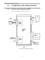
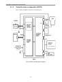
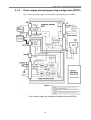
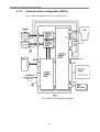
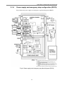
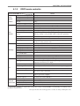
SRCD/SRCP
YAMAHA ROBOT CONTROLLER ERCX/SRCX/DRCX
CE marking
Supporting Supplement Manual
ENGLISH
E
E72-Ver. 3.00
INTRODUCTION
Thank you for purchasing the YAMAHA ERCX/SRCX/DRCX series robot controller.
This supplement manual describes the CE marking for ERCX/SRCX/DRCX series robot controller.
When shipping the ERCX/SRCX/DRCX series robot controller to or use it in Europe,
please be sure to read this manual and follow the instructions for correct operation.
This supplement manual describes only the items related to the CE marking. For basic
operations and programming of the robot controller, refer to the instruction manual for
the robot controller.
MEMO
Contents
Chapter
Chapter
1
CE marking ............................................................1
1-1
1-2
1-3
1-4
1-5
1-6
1-7
Safety Information .............................................................................. 2
CE marking ........................................................................................ 3
Safety precautions during robot operation ......................................... 5
Safety precautions during maintenance ............................................. 5
Precautions for motor overload .......................................................... 5
Warning labels.................................................................................... 6
Operating environment ....................................................................... 8
2
Configuration and Connection............................. 9
2-1 Configuration of CE marking controller ............................................ 10
2-2 Connecting the Power Supply .......................................................... 16
Chapter
3
EMC Countermeasures ....................................... 20
3-1 Typical component layout for EMC countermeasures ...................... 21
3-2 Precautions for Cable Connections .................................................. 23
Chapter
4
SPECIFICATIONS ................................................ 24
4-1 CE marking ...................................................................................... 25
MEMO
CHAPTER
1234567890123456789012345678901212345678901234567890123456789012123456789012345678901234567890
1234567890123456789012345678901212345678901234567890123456789012123456789012345678901234567890
1234567890123456789012345678901212345678901234567890123456789012123456789012345678901234567890
1234567890123456789012345678901212345678901234567890123456789012123456789012345678901234567890
1234567890123456789012345678901212345678901234567890123456789012123456789012345678901234567890
1234567890123456789012345678901212345678901234567890123456789012123456789012345678901234567890
1234567890123456789012345678901212345678901234567890123456789012123456789012345678901234567890
1234567890123456789012345678901212345678901234567890123456789012123456789012345678901234567890
1
CE marking
CHAPTER1 CE marking
1-1
Safety Information
To ensure correct and safe use of YAMAHA industrial robots, carefully read this supplement manual and make yourself well acquainted with the contents. FOLLOW THE
WARNINGS, CAUTIONS AND USER’S INCLUDED IN THIS SUPPLEMENT
MANUAL.
It is not possible to detail all safety items within the limited space of this supplement
manual. So it is essential that the user have a full knowledge of basic safety rules and
also that the operator makes correct judgments on safety procedures during operation.
Industrial robots are highly programmable, mechanical devices that provide a large degree of freedom when performing various manipulative tasks. Failure to take necessary
safety measures or mishandling due to not following the instruction in this supplement
manual may result in trouble or damage to the robot and injury to personnel (robot operator or service personnel) including fatal accidents.
Warning information in this supplement manual is shown classified into the following
items.
DANGER
Failure to follow DANGER instruction will result in severe injury or death to the robot
operator, a bystander or a person inspecting or repairing the robot.
WARNING
Failure to follow WARNING instruction could result in severe injury or death to the
robot operator, a bystander or a person inspecting or repairing the robot.
CAUTION
Failure to follow CAUTION instruction may result in injury to the robot operator, a
bystander or a person inspecting or repairing the robot, or damage to the robot and/or
robot controller.
2
CHAPTER1 CE marking
1-2
CE marking
This section provides a basic description of how YAMAHA robot series products are
compatible with CE marking.
1-2-1
Safety standards
■ Safety precaution for EC directive applicability
The YAMAHA robot series products (robots and controllers) do not fall within the
robot systems category. We define the YAMAHA robot series products as equipment
to be incorporated (built-in equipment) into your system, and declare that our products conform to the EC directives only within the scope of that equipment. Therefore,
although CE marking is affixed to any single unit of YAMAHA robot series products,
this means that use of any single unit of YAMAHA robot series products is not guaranteed to conform to the EC directives. When you ship your finished system to or use
it in Europe, you are required to verify that your system conforms to EC directives.
Differences between the YAMAHA robot series products (robots and
controllers) and robot systems.
YAMAHA robot series products (robots and controllers) are components used to
assemble a robot system and therefore do not constitute a robot system.
This is because YAMAHA robot series products do not include the end effector,
equipment, devices or sensors required for the robot to perform its tasks, which
are listed in the “Robot System” definition in Clause 3.2.20 of the EN775:1992
standard.
■ Applicable directives and standards
The table below shows directives and related standards applied to make YAMAHA
robots compatible with the CE marking.
EC Directives
Machinery directives
98/37/EC
Low-voltage directives
73/23/EEC
93/68/EEC
EMC directives
89/336/EEC
92/31/EEC
93/68/EEC
Related Standards
Note
EN292
EN1050
: Safety of machinery - basic concepts
: Safety of machinery - risk assessment
*1
EN60204-1
: Safety of machinery - electrical
equipment of machines
*2
EN55011
EN61000-6-2
: Emission / ISM equipment
: Immunity / Industrial environment
*3
*1: YAMAHA robot series products are built-in equipment unnecessary to adapt to the machinery directives.
However, YAMAHA robot series products conform to the above standards regarding the required items for
basic health and safety.
*2: The SRCX and DRCX controllers conform to the above directives and related standards. However, the ERCX
controller operates on DC 24V and is therefore excluded from the above directives and related standards.
*3: YAMAHA robot series products are tested according to the above directives and related standards. EMC
countermeasures for a single unit of YAMAHA robots are described in Chapter 3, “EMC Countermeasures”.
3
CHAPTER1 CE marking
1-2-2
Robots subject to CE marking
The ERCX/SRCX/DRCX series controller can be used with the following robot series
products which are subject to CE marking.
Robot Type
ERCX
SRCX
DRCX
Single-axis robot
FLIP-X series
Cartesian type robot
XY-X series
Pick-and-place type robot
YP-X series
(Except some models)
For more details on model numbers and combinations with peripheral units, consult
YAMAHA or YAMAHA dealers.
1-2-3
Safety measures
■ Operating conditions
The following description gives major operating conditions for using YAMAHA robot series products.
● EMC (Electromagnetic compatibility)
YAMAHA robot series products are products for use in an industrial environment.
(Refer to the definition applicable to the EMC directives: Under “Scope” in the first
article of the EN61000-6-2 standard.
In order to ensure your product conforms to EMC directives, you must evaluate your
finished product (entire system) and take necessary countermeasures. EMC countermeasures for single units of YAMAHA robots are listed in “Chapter 3 EMC Countermeasures” on page 20.
● Installation conditions
• Since YAMAHA robot series products are built-in equipment, they have a Class I
protective structure against electrical shock. The robot and controller must therefore be grounded properly to prevent possible electrical shock. For more details,
refer to “2-2-4 Protective bonding” (page 19) in this supplement manual and the
Robot User’s Manual.
• The robot controller case is not designed as an enclosure that conforms to EN602041 standard. Therefore you must provide appropriate protection against the danger
of electrical shock due to inadvertent contact and external environmental problems
(dust, water, etc.)
• Insulation co-ordination is designed to meet the following conditions. (Refer to the
IEC60664-1 standard.)
Overvoltage category II
Pollution degree II
Take proper countermeasures as needed if the robot or controller is used in environments worse than these levels.
● Explosion-proof
YAMAHA standard robots and robot controllers are not designed to meet explosionproof specifications. Do not use the robot and controller in environments containing
inflammable gas, gasoline or solvent. Explosions or fire may otherwise result.
4
CHAPTER1 CE marking
■ Safety measures for robot
● Protective measures against electrical shock (except robots for ERCX controller)
Use the protective ground terminal to ensure safety. Refer to the user’s for details.
1-3
Safety precautions during robot operation
■ The robot must be operated by a person who has received Robot Training
from YAMAHA or an authorized YAMAHA dealers.
■ During operation of the robot, be sure to stay out of the working area of the
manipulator. Install a safeguard enclosure to keep anyone away from the working area or provide a gate interlock using an area sensor that triggers emergency stop when anyone enters the working area.
1-4
Safety precautions during maintenance
■ Never disassemble the robot or controller. In cases where you have to replace
or repair parts used in the robot or controller, first consult with us and follow
the user’s we provide.
■ Before beginning maintenance for the robot or controller, be sure to turn off
the power to the controller. Even after turning off the controller, there are some
parts in the controller which are still hot or at a high voltage. Always wait for at
least 5 minutes after the controller is turned off.
1-5
Precautions for motor overload
Since abnormal operation of the motor such as “overload” is detected by software, the
controller parameters must be set correctly to match the motor type used in the robot
which is connected to the controller.
Prior to shipping, the controller parameters are preset to match the robot model to be
used. When connecting to the robot to the controller, check the robot model again. If any
abnormality is found during operation, stop the controller and contact us for corrective
action.
5
CHAPTER1 CE marking
1-6
Warning labels
The following labels are affixed to the SRCX/DRCX controller to emphasize what you
must do or must not do to ensure safety. (These warning labels are not affixed to the
ERCX.)
To use the YAMAHA robot and controller safely and correctly, be sure to observe the
caution and instruction on the labels.
■ Label warning of
Read instruction
manual
1-6-1
■ Label warning of
high temperature
■ Label warning of
electrical shock
■ Label warning of
200V only
Warning labels locations
High temperature
warning label
Electrical shock
warning label
“Read instruction
manual” label
AC 200V warning label
SRCX controller
High temperature
warning label
Electrical shock
warning label
“Read instruction
manual” label
AC 200V warning label
DRCX controller
6
CHAPTER1 CE marking
1-6-2
Meaning of warning labels
■ “Read instruction manual” label
This label indicates that important items you must know are described in the instruction manual. The followings are particularly important.
• The power fuses in the controller are located on both sides of L/N. (See Fig. 2-4,
“Power supply and emergency stop circuit block diagram (SRCX)”(page 13), and
also Fig. 2-6, “Power supply and emergency stop circuit block diagram
(DRCX)”(page 15).
• When one end of the power supply is grounded, connect the grounded side to the N
side of the controller power input terminal.
to the protec• Be sure to connect the controller’s protective conductor terminal
tive conductor on the user side.
to the protective
• Be sure to connect the robot’s protective conductor terminal
conductor of the user’s system.
■ High temperature warning label
Indicates that the area around this waning label is very hot. Do not touch any part of
this area during operation to prevent burn.
■ Electrical shock warning label
Indicates that a high voltage is applied to some parts in the controller. Never touch the
connectors or terminals during operation.
■ AC 200V warning label
Indicates that the power supply connected to the controller must be AC 200V±10%.
7
CHAPTER1 CE marking
1-7
Operating environment
■ Installation location
Install the robot controller indoors, at a height of less than 1000 meters above sea
level.
■ Operating temperature
The ambient temperature should be maintained within a range of 0 to 40°C during
operation. This is the range in which continuous operation of the robot controller is
guaranteed according to the initial specifications. If the robot controller is installed in
a narrow space, heat generated from the controller itself and from peripheral equipment may drive the temperature above the allowable operating temperature range.
This may result in thermal runaway or malfunction and may lower component performance along with shortening their useful service life. So be sure to install the controller in locations with a vent having a natural air flow. If this proves insufficient
provide forced air-cooling.
■ Operating humidity
The ambient humidity of the robot controller should be kept 35 to 85% RH (no condensation) in order to guarantee continuous operation within the initial specifications.
■ Storage temperature
The controller should be stored in a location having an ambient temperature range
from -10 to +65°C when not being used. If the robot controller is stored in a location
at high temperatures for extended periods, deterioration of the electronic components
may occur and the memory backup time may decrease.
■ Storage humidity
The controller should be stored in a location having an ambient humidity below 95%
RH when not being used. If the robot controller is stored in a location with high humidity for an extended period of time, rust may form on the electronic components.
■ Vibration and shock
Do not apply excessive shocks or constant vibrations to the robot controller. Install the
robot controller in a location not subject to vibrations.
■ Atmosphere (gas etc.)
Do not install the robot controller in locations where conductive dust particles, hydrogen sulfide gas or sulfurous acid gas are present. Such an atmosphere may cause the
components to erode.
8
CHAPTER
1234567890123456789012345678901212345678901234567890123456789012123456789012345678901234567890
1234567890123456789012345678901212345678901234567890123456789012123456789012345678901234567890
1234567890123456789012345678901212345678901234567890123456789012123456789012345678901234567890
1234567890123456789012345678901212345678901234567890123456789012123456789012345678901234567890
1234567890123456789012345678901212345678901234567890123456789012123456789012345678901234567890
1234567890123456789012345678901212345678901234567890123456789012123456789012345678901234567890
1234567890123456789012345678901212345678901234567890123456789012123456789012345678901234567890
1234567890123456789012345678901212345678901234567890123456789012123456789012345678901234567890
2
Configuration and Connection
This chapter explains the configuration of the CE marking controller and the connections to the power supply.
CHAPTER2 Configuration and Connection
2-1
Configuration of CE marking controller
2-1-1
Controller basic configuration (ERCX)
Fig.2-1 shows the ERCX controller basic block diagram.
Fig.2-1 ERCX controller block diagram
10
CHAPTER2 Configuration and Connection
2-1-2
Power supply and emergency stop configuration (ERCX)
Fig.2-2 shows the power supply and emergency stop block diagram for ERCX.
Fig.2-2 Power supply and emergency stop block diagram (ERCX)
11
CHAPTER2 Configuration and Connection
2-1-3
Controller basic configuration (SRCX)
Fig.2-3 shows the SRCX controller basic block diagram.
Fig.2-3 SRCX controller block diagram
12
CHAPTER2 Configuration and Connection
2-1-4
Power supply and emergency stop configuration (SRCX)
Fig.2-4 shows the power supply and emergency stop block diagram for SRCX.
Fig.2-4 Power supply and emergency stop block diagram (SRCX)
13
CHAPTER2 Configuration and Connection
2-1-5
Controller basic configuration (DRCX)
Fig.2-5 shows the DRCX controller basic block diagram.
Fig.2-5 DRCX controller block diagram
14
CHAPTER2 Configuration and Connection
2-1-6
Power supply and emergency stop configuration (DRCX)
Fig.2-6 shows the power supply and emergency stop block diagram for DRCX.
Fig.2-6 Power supply and emergency stop block diagram (DRCX)
15
CHAPTER2 Configuration and Connection
2-2
Connecting the Power Supply
2-2-1
Power supply
■ ERCX controller
DriverType
Power supply voltage
No. of phases
Frequency
Max. power consumption
-
DC24V ±10%
-
-
3A
■ SRCX controller
DriverType
Power supply voltage
No. of phases
Frequency
Max. power consumption
05
AC200V ±10%
Single phase
50/60Hz
400 VA
10
AC200V ±10%
Single phase
50/60Hz
600 VA
20
AC200V ±10%
Single phase
50/60Hz
1000 VA
Max. power consumption
■ DRCX controller
DriverType
Power supply voltage
No. of phases
Frequency
0505
AC200V ±10%
Single phase
50/60Hz
500 VA or less
0510
AC200V ±10%
Single phase
50/60Hz
700 VA or less
0520
AC200V ±10%
Single phase
50/60Hz
1100 VA or less
1005
AC200V ±10%
Single phase
50/60Hz
700 VA or less
1010
AC200V ±10%
Single phase
50/60Hz
900 VA or less
1020
AC200V ±10%
Single phase
50/60Hz
1300 VA or less
2005
AC200V ±10%
Single phase
50/60Hz
1100 VA or less
2010
AC200V ±10%
Single phase
50/60Hz
1300 VA or less
2020
AC200V ±10%
Single phase
50/60Hz
1600 VA or less
CAUTION
On the SRCX and DRCX controllers designed for CE marking, the power supply must
be AC 200V±10%.
If the power supply voltage drops below the above listed range during operation, an
alarm circuit triggers so that the controller operation misht return to the initial conditions
or come to an alarm stop. To avoid such problems from power supply fluctuations, a
stable power supply with less than ±10% fluctuation should be used.
The controller has a capacitor input type power supply, so a large current surge occurs
when the power is turned on. Avoid using quick-blow circuit breakers and fuses.
For the same reason, avoid turning the power off and on again repeatedly within an
interval of less than 10 seconds. This could eventually damage the main circuit elements
in the controller.
16
CHAPTER2 Configuration and Connection
C A U T I O N (ERCX controller only)
The power consumption listed above is for ERCX controller only. Additional power
should be supplied for the mechanical brake and I/O control via the I/O connector. If the
current supplied to the controller is insufficient, an alarm stop or abnormal operation
may occur. So, carefully select a 24V power supply to match your application needs. A
24V power supply with adequate current capacity may help to upgrade robot performance. For detailed information, contact our sales office or dealer.
Power supply current required by I/O connector of ERCX controller.
Power supply current required by I/O control:
50mA for emergency stop circuit + current capacity for I/O drive
(depends on user application)
Power supply current required by brake control:
300mA for mechanical brake (if used)
2-2-2
Connecting the power supply (ERCX)
Use the power plug (supplied) to connect the power supply to the POWER connector on
the ERCX controller. Referring to the figure below, make correct connections to each
terminal. Misconnections may lead to serious accidents such as fire. The end of each
wire must be fastened with a screw so that it will not come off the plug. If the controller
becomes unstable due to noise, use of a ferrite core on the power supply line is recommended as shown below.
ERCX
1
2
3
1. 24V
2. N(0V)
3. (Grand)
Wire thicker than
2
1.25mm
Fig. 2-7 Power supply connections
CAUTION
The ERCX controller does not have a power switch. Be sure to provide a power supply
breaker (isolation) of the correct specifications that will turn power on and off to the
entire system including the robot controller.
17
CHAPTER2 Configuration and Connection
CAUTION
When connecting the power supply to the ERCX controller, the cable length between the
ERCX controller and the AC adapter for supplying DC power to the ERCX controller
should be less than 10 meters, in order to prevent external surge intrusion into the power
cable. Also take the necessary measures so that no one except service personnel can
unplug the power cable.
DANGER
Before you start wiring work, make sure that the power for the entire system is turned
off. Doing wiring work while power is still on can cause electrical shocks.
2-2-3
Connecting the power supply (SRCX, DRCX)
Connect the power supply to the terminal block on the controller. Make the correct connections to each terminal while referring to the marks printed on the panel. Misconnections
may lead to serious accidents such as fire. The end of each wire must be crimped so that
it will not come off the terminal block. On the SRCX and DRCX controllers designed
for CE marking, the power supply must be AC 200V±10%.
1. L (AC IN)
2. N (AC IN)
3. (Ground)
4. NC (No connection)
5. T1 and T2 (for input voltage setting)
Leave open
Fig. 2-8 Power supply connections
CAUTION
The SRCX and DRCX controllers does not have a power switch. Be sure to provide a
power supply breaker (isolation) of the correct specification that will turn power on and
off to the entire system including the robot controller.
DANGER
Before you start wiring work, make sure that the power supply for the entire system is
turned off. Doing wiring work while power is still on can cause electrical shock.
18
CHAPTER2 Configuration and Connection
2-2-4
Protective bonding
The robot controller is built in to the equipment, so it has a protective structure of Class
I against electrical shock. To prevent electrical shock, be sure to ground the protective
conductor terminal of the robot controller by connecting it to the protective conductor of
the entire system. The protective conductor terminal of the robot controller is marked
with the symbol shown below.
Protective conductor terminal symbol : 417-IEC-5019
2-2-5
Insulation co-ordination
Insulation co-ordination was designed to meet the following conditions. (Refer to the
description of IEC60664-1 standards.)
■ Overvoltage category II
■ Pollution degree II
If the robot or controller is used in environments worse than these levels, take proper
countermeasures as needed.
2-2-6
Isolation Resistance and Voltage BreakdownTests
Never attempt isolation resistance tests or voltage breakdown tests on the controller.
Since capacitive grounding is provided between the controller body and 0V, these tests
may result in detecting excessive leakage current or damage to internal circuitry. If these
tests are required, please consult your YAMAHA sales office or representative.
19
CHAPTER
1234567890123456789012345678901212345678901234567890123456789012123456789012345678901234567890
1234567890123456789012345678901212345678901234567890123456789012123456789012345678901234567890
1234567890123456789012345678901212345678901234567890123456789012123456789012345678901234567890
1234567890123456789012345678901212345678901234567890123456789012123456789012345678901234567890
1234567890123456789012345678901212345678901234567890123456789012123456789012345678901234567890
1234567890123456789012345678901212345678901234567890123456789012123456789012345678901234567890
1234567890123456789012345678901212345678901234567890123456789012123456789012345678901234567890
1234567890123456789012345678901212345678901234567890123456789012123456789012345678901234567890
3
EMC Countermeasures
To conform to EMC directives, implement the appropriate EMC countermeasures for your finished product
(entire system). The following description and circuits are typical EMC countermeasures for a single unit of
YAMAHA robot, just for your reference.
CHAPTER3 EMC Countermeasures
3-1
Typical component layout for EMC countermeasures
The following countermeasures are typical methods for testing the robot and controller
under YAMAHA installation conditions. When the robot and controller are used while
installed in your system, the actual test results may differ depending on installation conditions.
3-1-1
Typical component layout for EMC countermeasures (ERCX)
Fig.3-1 EMC countermeasures for ERCX
3-1-2
Typical component layout for EMC countermeasures (SRCX)
Fig.3-2 EMC countermeasures for SRCX
21
CHAPTER3 EMC Countermeasures
3-1-3
Typical component layout for EMC countermeasures (DRCX)
Fig.3-3 shows a typical component layout for EMC countermeasures when the DRCX
controller is used in combination with a YAMAHA cartesian or pick-and-place type
robot.
Fig.3-4 shows a typical component layout for EMC countermeasures when the DRCX
controller is used in combination with two YAMAHA single-axis robots.
EMC countermeasures for DRCX and Cartesian or P&P robot
Fig.3-3 EMC countermeasures 1 for DRCX
EMC countermeasures for DRCX and single-axis robots
Fig.3-4 EMC countermeasures 2 for DRCX
22
CHAPTER3 EMC Countermeasures
3-2
Precautions for Cable Connections
Various cables are used to connect the robot controller to peripheral devices. Lay out AC
cables as separately from low DC cables as possible.
■ AC cables
• Power cable
• Motor cable
■ Low DC cables
• TPB cable, communication cable
• I/O cable
• Robot I/O cable
23
CHAPTER
1234567890123456789012345678901212345678901234567890123456789012123456789012345678901234567890
1234567890123456789012345678901212345678901234567890123456789012123456789012345678901234567890
1234567890123456789012345678901212345678901234567890123456789012123456789012345678901234567890
1234567890123456789012345678901212345678901234567890123456789012123456789012345678901234567890
1234567890123456789012345678901212345678901234567890123456789012123456789012345678901234567890
1234567890123456789012345678901212345678901234567890123456789012123456789012345678901234567890
1234567890123456789012345678901212345678901234567890123456789012123456789012345678901234567890
1234567890123456789012345678901212345678901234567890123456789012123456789012345678901234567890
4
SPECIFICATIONS
CHAPTER4 SPECIFICATIONS
4-1
CE marking
4-1-1
ERCX sereis controller
Model
Specification item
Applicable motor capacitance
Basic
External dimensions
specifiWeight
cations
Used power supply voltage
No. of controllable axes
Control method
Position detection method
Speed setting
Axis
Acceleration/deceleration
control
setting
Servo adjustment
No. of encoder pulses
Lead length
Memory
I/O
ROM
RAM
No. of program steps
No. of programs
No. of points
No. of multi tasks
Origin detection method
Teaching method
Auxiliary memory unit
I/O input
I/O output
Drive power supply
Brake output
Emergency stop input
Serial interface
Network (option)
Ambient temperature
General
Storage temperature
specification Ambient humidity
CE marking
ERCX
DC24V, 30W or less
W30 × H250 × D157mm
0.9kg
DC24V±10%, 3A*1
1 axis
AC full digital servo PTP
Resolver with multi-turn data backup function
100-step setting possible per program step
Automatically set according to robot type and transportation weight.
100-step setting is also possible with acceleration parameter.
Handled with parameters (special). Servo gain, current limit, etc.
16384P/R
Lead length is selectable during initialization or by parameter
setting
256K bytes (with CPU incorporated)
128K bytes with 64K lithium battery backup (5-year life)
3000 steps/total or less, 255 steps/program
100
1000 points
4
Origin search by stroke end detection or absolute reset
MDI (coordinate value input), teaching playback, direct teaching
IC memory is available as TPB option
General-use 16 points, special-use 8 points
General-use 13 points, special-use 3 points, open collector
output (0.1A/24V maximum per output)
External DC24V±10%, more than 50mA*2
Relay output (for 24V/300mA brake), one channel
Normal closed contact input (origin return not required after
emergency stop is released)
One RS-232C channel (for communication with TPB or general
purpose personal computer)
CC-Link, DeviceNet, EtherNet
0 to 40 degrees
-10 to 65 degrees
35 to 85%RH (with no condensation)
See 1-2-1, “Safety standards”, and Chapter 3, “EMC Countermeasures”.
*1: When controlling a brake and I/O operations, a separate 24V power supply with a necessary capacity must be connected to the I/O connectors.
The robot performance may be enhanced if a 24V power supply with an adequately large capacity is available. Please consult us for more details.
*2: When no brake and I/O control are used. An additional power supply will be needed to provide power for the brake and I/O control.
Note) Specifications and external appearance are subject to change without prior notice.
25
CHAPTER4 SPECIFICATIONS
4-1-2
SRCX sereis controller
Model
Specification item
Applicable motor capacitance*1)
Basic
Max. power consumption
specifiExternal dimensions
cations
Weight
Used power supply voltage
No. of controllable axes
Control method
Position detection method
Speed setting
Axis
Acceleration/deceleration
control
setting
Servo adjustment
No. of encoder pulses
Lead length
SRCX-05
SRCX-10
SRCX-20
200V, 100W or less 200V, 200W or less 200V, 600W or less
400VA
600VA
1000VA
W78 × H250 × D157mm
1.5kg
Single-phase AC200V within ±10% 50/60Hz
1 axis
AC full digital servo PTP
Resolver with multi-turn data backup function
100-step setting possible per program step
Automatically set according to robot type and transportation weight.
100-step setting is also possible with acceleration parameter.
Handled with parameters (special). Servo gain, current limit, etc.
16384P/R
Lead length is selectable during initialization or by parameter
setting (special function)
ROM
256K bytes (with CPU incorporated)
RAM
128K bytes with 64K lithium battery backup (5-year life)
No. of program steps
3000 steps/total or less, 255 steps/program
No. of programs
100
Memory
No. of points
1000 points
No. of multi tasks
4
Teaching method
MDI (coordinate value input), teaching playback, direct teaching
Auxiliary memory unit
IC memory is available as TPB option
I/O input
General-use 16 points, special-use 8 points
I/O output
General-use 13 points, special-use 3 points, open collector
output (0.5A/24V maximum per output)
External drive power supply 24V/600mA (when not using brake)
Brake output
Relay output (for 24V/300mA brake), one channel, built-in power supply (24V)
Origin sensor input
Connectable to a DC24V B-contact sensor
Emergency stop input
Normal closed contact input (origin return not required after
emergency stop is released)
Serial interface
One RS-232C channel (for communication with TPB or general
purpose personal computer)
Network (option)
CC-Link, DeviceNet, EtherNet
Ambient temperature
0 to 40 degrees
General
Storage temperature
-10 to 65 degrees
specification Ambient humidity
35 to 85%RH (with no condensation)
CE marking
See 1-2-1, “Safety standards”, and Chapter 3, “EMC Countermeasures”.
*1) The regenerative unit (RGU-2) is required to operate a load with large inertia or a robot model specified by YAMAHA.
Note) Specifications and external appearance are subject to change without prior notice.
26
CHAPTER4 SPECIFICATIONS
4-1-3
DRCX sereis controller
Model
Specification item
Applicable motor capacitance
Basic
Max. power consumption
specifiExternal dimensions
cations
Weight
Used power supply voltage
No. of contr ollable axes
Control method
Position detection method
Speed setting
Axis
Acceleration/deceleration
control
setting
Servo adjustment
No. of pulses
Lead length
Memory
I/O
ROM
RAM
No. of program steps
No. of programs
No. of points
No. of multi tasks
Teaching method
Auxiliary memory unit
I/O input
I/O output
Exter nal drive power suppl y
Brake output
Origin sensor input
Emergency stop input
Serial interface
Network (option)
Ambient temperature
Storage temperature
General
specification Ambient humidity
CE marking
DRCX
Total power 1200W max. *
1600VA
W100 × H250 × D157mm
2.1kg
Single-phase AC200V within ±10% 50/60Hz
2 axes
AC full digital servo PTP, CP*2), ARC *2)
Resolver with multi-turn data backup function
100-step setting possible per program step
Automaticallyset according to robot type and transportation weight.
100-ste p setting is also possible with acceler ation parameter.
Handled with parameters (special). Servo gain, current limit, etc.
16384P/R
Lead length can be selected during initial processing or by
parameter setting (custom order)
256K bytes (with built-in CPU)
128K bytes with 64K lithium battery backup (5-year life)
3000 steps/total or less, 255 steps/program
100
1000 points
4
MDI (coordinate value input), teaching playback, direct teaching
IC memor y is available as TPB option
General-use 16 points, special-use 8 points
General-use 13 points, special-use 3 points, open collector
output (0.5A/24V max. per output)
1)
DC24V/900mA (when not using brake)
Relay output (for 24/300mA brake), two channel, built-in power supply (24V)
Connectable to a DC24V B-contact senser
Normal closed contact input (origin return not required after
emergency stop is released)
One RS-232C channel (for communication with TPB or general
purpose personal computer)
CC-Link, DeviceNet, EtherNet
0 to 40 degrees
-10 to 65 degrees
35 to 85%RH (with no condensation)
See 1-2-1, “Safety standards”, and Chapter 3, “EMC Countermeasures”.
*1) A regenerative unit (RGU-2) is required when operating robot models specified by YAMAHA or a robot handling a load with large inertia.
*2) Only for Cartesian robot.
Note) Specifications and external appearance are subject to change without prior notice.
27
Supporting Supplement Manual
SRCD/SRCP
ERCX/SRCX/DRCX
Robot Controller
May 2007
Ver. 3.00
CE marking
This manual is based on Ver. 3.00 of Japanese manual.
© YAMAHA MOTOR CO., LTD.
IM Operations
All rights reserved. No part of this publication may be reproduced in
any form without the permission of YAMAHA MOTOR CO., LTD.
Information furnished by YAMAHA in this manual is believed to be
reliable. However, no responsibility is assumed for possible
inaccuracies or omissions. If you find any part unclear in this manual,
please contact YAMAHA or YAMAHA sales representatives.