1
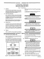
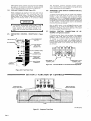
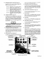
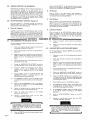
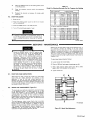
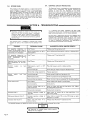
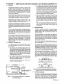
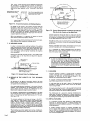
February
1980
FORM: OM-540A
Effective With Serial No. HK321565
MODEL
SCE-1A
SCE-3A
SCE-5A
SCM-lA
SCM-3A
SCM-5A
.tcc
._
,
I.
~
5
OWN E RS
MANUAL
I11dIER
MILLER ELECTRIC MFG. CO.
718 S. BOUNDS ST. P.O. Box 1079
APPLETON, WI
54912 USA
NWSA CODE NO. 4579
PRINTED
IN U.S.A.
~%
L
~L~
L~
~
L&P
~
LIMITED WARRANTY
EFFECTIVE: JUNE 1. 1979
This warranty supersedes all previous MILLER warranties and is ex
clusive with no other guarantees or warranties expressed or implied.
(
LIMITED WARRANTY-Subject to the terms and conditions
hereof, Miller Electric Mfg. Co., Appleton, Wisconsin warrants
to its Distributor/Dealer that all new and unused Equipment
furnished by Miller is free from defect in workmanship and
material as of the time and place of delivery by Miller. No warranty is made by Miller with respect to engines, trade accessories or other items manufactured by others. Such
engines, trade accessories and other items are sold subject to
the warranties of their respective manufacturers, if any
All
engines are warranted by their manufacturer for one year from
date of original purchase.
.
Except
specified below, Millers warranty
does not
apply
to components having normal useful life of less than one (1)
year, such as spot welder tips, relay and contactor points,
as
MILLERMATIC parts that come in contact with the welding
wire including nozzles and nozzle insulators where failure does
from defect in
not result
workmanship
or
material.
Miller shall be required to honor warranty claims
Equipment in the event of failure resulting from
on
ranted
within the
ment to
following periods
the original user:
from the date of
a
war-
defect
delivery of Equip-
As
matter of
a
submitted by the
general policy on1y, Miller may honor claims
original user within the foregoing periods.
In the case of Millers breach of warranty or any other duty
with respect to the quality of any goods, the exclusive remedies
therefore shall be, at Millers option 11) repair or (21 replacement
writing by Miller in appropriate cases, (31
repair or replacement at an authorized
Miller service station or 141 payment of or credit for the purchase
price (less reasonable depreciation based upon actual use) upon
return of the goods at Customers risk and expense. Upon receipt
or, where authorized in
the reasonable cost of
of notice of apparent defect or failure, Miller shall instruct the claimant on the warranty claim procedures to be followed.
ANY EXPRESS WARRANTY NOT PROVIDED HEREIN AND
ANY IMPLIED WARRANTY,
GUARANTY OR REPRESENTA-
PERFORMANCE, AND ANY REMEDY FOR
BREACH OF CONTRACT WHICH, BUT FOR THIS PROVISION,
MIGHT ARISE BY IMPLICATION, OPERATION OF LAW,
CUSTOM OF TRADE OR COURSE OF DEALING, INCLUDING
lION
ANY
AS
TO
IMPLIED WARRANTY OF MERCHANTABILITY OR OF
FITNESS FOR PARTICULAR
WITH RESPECT TO
PURPOSE,
ANY AND ALL EQUIPMENT FURNISHED BY MILLER (S EX
CLUDED AND DISCLAIMED BY MILLER.
1. Arc welders, power sources and components
2. Original main power rectifiers
(labor
-
.
1 year
onlyl
welding guns and feeder/guns
-
3.
All
4.
All other Millermatic Feeders
5.
Replacement
6.
Batteries
or
1 year
3 years
EXCEPT
WRITING,
90 days
1 year
repair parts, exclusive of labor
.
60 days
6 months
ULTIMATE
AS
EXPRESSLY
MILLER
PURCHASE
BY
that Miller is notified in
of the date of such failure.
.~,
J~
writing
within thirty (30) days
ARE
BY
MILLER
INTENDED
IN
FOR
COMMERCIAL/INDUSTRIAL
USERS AND FOR OPERATION BY PERSONS TRAINED AND
EXPERIENCED
WELDING
IN
THE
EQUIPMENT
USE
AND
CONSUMER USE. MILLER
provided
PROVIDED
PRODUCTS
TO,
AND
NO
RESELLER
AND
NOT
MAINTENANCE
FOR
CONSUMERS
WARRANTIES DO NOT EXTEND
IS AUTHORIZED TO EXTEND
MILLERS WARRANTIES TO, ANY CONSUMER.
~
J~
OF
OR
TABLE OF CONTENTS
Section No.
SECTION 1
1
1
-
Page No.
INTRODUCTION
General
1.
1
2.
Receiving-Handling
1
3. Description
1-4. Safety
-
1
1
-
SECTION 2
1
INSTALLATION
2- 1.
Electrical Input Connections
1
2. 2.
2
2
2
-
-
-
Secondary Connections
3. Shielding Gas Con nØctions
1
1
Coolant Connections
4.
2
5. Contactor Control Receptacle
2
2. 6.
Emergency Stop Switch Connections
2- 7. Manual Control Connections Of Sequence C
SECTION 3
3
-
1.
3- 2.
3
3
3
-
-
-
-
-
-
3
5.
Manual Control Of
3
3
4
Sequence C
4
High-Frequency Control
SEQUENCE OF OPERATION
Gas
4
Shielded Metal-Arc
4
Tungsten-Arc Welding (GTAW)
Welding (SMAW)
3. Shutting Down
1.
SECTION 5
5
3
Current Control
Weld Switch
4- 2.
4
Sequence Control Function
4.
SECTION 4
4
FUNCTION OF CONTROLS
3. Start Switch (SCE/SCM-1A and 2A)
3- 6.
2
2
5
MAINTENANCE
5
High Voltage Capacitors
Spark Gap Adjustment
3. Bypass Panel
1.
5- 2.
5
5
6
5
-
-
Control Circuit Protection
4.
6
SECTION 6
TROUBLESHOOTING
SECTION 7
CERTIFICATION FOR HIGH FREQUENCY ARC WELDING EQUIPMENT
7- 1.
General
7
7
2.
General Information
7
3.
Power Service
7
7
7
7
7
-
-
-
-
-
4. Welding Machine
7
5. Welding Leads
8
6.
Wiring
In The Vicinity Of The
Welding
7- 7.
Grounds
7
8.
Metal
9.
Individual Installation Certification
7
-
-
Building
7-10. Check List
Area
8
8
8
9
9
SECTION 1
INTRODUCTION
-
Dime nsions (Inches)
Weight (Pounds)
Height
Width
Depth
Net
Shipping
33-1/4
26-1/4
10-3/4
168
230
Figure 1-1. Specifications
1-1.
GENERAL
generator manual should be read completely. This will help
avoid possible injury due to misuse or improper welding
prepared especially for use in familiar
izing personnel with the design, installation operation, main
tenance, and troubleshooting of this equipment. All informa
tion presented herein should be given careful consideration to
assure optimum performance of this equipment.
applications.
This manual has been
1-2.
The
following definitions apply to CAUTION, IMPORTANT,
and NOTE blocks found throughout this manual:
RECEIVING-HANDLING
Prior to installing this equipment, clean all packing material
from around the unit and carefully inspect for any damage
that may have occurred during shipment. Any claims for loss
or damage that may have occurred in transit must be filed by
the purchaser with the carrier. A copy of the bill of lading
and freight bill will be furnished by the carrier on request if
Under this heading, installation, operating, and main
procedures or practices will he found that if
carefully followed may create a hazard to per-
tenance
not
sonnel.
occasion to file claim arises.
I
When requesting information concerning this equipment, it is
essential that Model Description and/or Stock Number and
Serial (or Style) Numbers of the equipment be supplied.
1-3.
DESCRIPTION
IL
1
U
heading, installation, operating, and main
tenance procedures or practices will be found that if
not carefully followed may result in damage to equip
.
Under
Sequence Controls are specifically designed to be used
in conjunction with an electric current controlled welding
power source. These Sequence Controls provide five different
sequences for either automatic or semi-automatic operation
of the various welding processes. The function of each
sequence is described in Section 3, FUNCTION OF CON
TROLS, in this manual. The SCE Models are equipped with
electronic timers in sequences B, C, and D. The SCM Models
are equipped with mechanical timers in sequences B, C, and
These
this
ment.
NOTE
D.
U
1-4.
SAFETY
Before the equipment is put into operation, the safety sec
at the front of the welding power source or welding
I
U
heading, explanatory statements will be
need special emphasis to obtain the most
efficient operation of the equipment.
Under
this
found
that
I
tion
SECTION 2
2-1.
-
INSTALLATION
welding
power
the link for the
ELECTRICAL INPUT CONNECTIONS
Refer to the Installation Section of the
welding
power
Refer to Figure 2-1 for positioning
required operating voltage.
source.
of
source
On the SCE/SCM-5A, the control transformer which provides
primary power to the control is located in the welding
Manual for instructions on connecting electrical input power
to the welding power source.
the
power source.
SCE/SCM-1A and 3A Models, inside the cabinet
on the lower right corner above the control transformer, is
either a three or a five pole terminal block with one jumper
link attached. The primary power supply to the Sequence
On
the
2-2.
Control is connected to this block. The jumper link must be
connected for the primary power supply voltage that will
correspond with the primary power supply voltage of the
(Figure 2-2)
unit was shipped wh the secondary inte r
connecting cables between the Sequence Control and
welding power source unconnected. It is therefore
necessary to route and secure the secondary inter
connecting cables (already attached to Sequence Con
trol) to the proper weld output terminals on the
welding power source. The secondary welding cables
should only be attached to the output terminals on
Sequence Control to achieve proper operation of this
230/460 VOLTS
~
460
230
SECONDARY CONNECTIONS
208/230/460 VOLTS
Refer
to
Owners
208
230
Installation Section of the welding power
Manual for proper weld cable size.
source
460
The secondary terminals on the Sequence Control are labeled
ELECTRODE and WORK. Connect the electrode holder
230/460/575 VOLTS
cable
to
the
terminal marked
ELECTRODE and the work
cable to the terminal marked WORK.
00
000
2-3.
230
460
TA-040 107-4
Figure 2-1.
Line
SHIELDING GAS CONNECTIONS
(Figure 2-2)
These
front panel and are
have a right-hand,
575
Voltage Jumper Link Arrangement
labeled
connections
are
IN-GAS-OUT.
located
The
on
the
connections
OM-540 Page 1
2-4.
gas
5/8-18 female thread. Connect the hose from the shielding
supply to the connection labeled IN. Connect the hose
control facilities. Either
from the electrode holder to the connection labeled OUT.
used in
COOLANT CONNECTIONS
This
(Figure 2-2)
2-6.
three-prong,
twistlock
receptacle provides
remote hand or
a
contactor
foot switch
can
be
conjunction with this receptacle.
EMERGENCY STOP SWITCH CONNECTIONS
2-3 and 3-2)
(Fig
ures
These
connections
located on the front panel and are
labeled IN-COOLANT-OUT. The connections have a lefthand, 5/8-18 female thread. Connect the hose from the
coolant supply to the connection labeled IN. Connect the
from
hose
the
are
electrode
holder
to
the connection
A five-pole terminal block with two jumper links attached,
located on the inside lower left corner of the cabinet,
provides a means of emergency stop connections of weld
sequences B, C, or 0. If it is desirable to connect an emergen
cy stop switch in the circuit, remove the jumper link that is
connected across the fourth and fifth terminals, counting left
labeled
OUT.
right. Connect a normally-closed switch to the terminals
from which the link was removed.
to
If
a
portable, self-contained coolant system
with
this
unit,
ensure
bypass capability
to
that
avoid
the
coolant
possible damage
With
the WELD switch in the AUTOMATIC position, weld
sequences B, C, or D may be interrupted at any time by
opening the emergency stop switch. Opening of this switch
will initiate sequence E (post-flow time).
is used
has
pump
the
to
when the coolant valve closes and coolant flow
motor
stops.
2-7.
2-5.
CONTACTOR
CONTROL
RECEPTACLE
MANUAL
CONTROL
CONNECTIONS
QUENCE C (Figures 2-3 and 3-2)
A
five-pole terminal block, with
located
provides
~
~
DC AMMETER
~
$
I
SE
(Figure
2-2)
WELD SWITCH
OF
To
HIGH-FREQUENCY
SWITCH
on
the
a
means
connect
an
two jumper links attached,
inside lower left corner of the cabinet,
of external switch control of sequence C.
external
switch
for
manual
control
of
sequence C, remove the jumper link connected across the
first and second terminals counting left to right. Connect a
L~
normally-open switch
was
to
the terminals from
which the link
removed.
START SWITCH
(ONLY ON
SCE/SCM-1 A)
GAS CONNECTIONS
COOLANT
CONNECTIONS
C ON TA CTO R
CONTROL
RECEPTACLE
ELECTRODE
TERMINAL
WORK
TERMINAL
TA-OlO 566
Terminal Block For External Switch
Figure 2-3.
Figure 2-2.
Front Panel View
SECTION 3- FUNCTION
CONTROLS
OF
POST-FLOW OF
PRE-FLOW OF
GAS & COOLANT
ANT
GAS &
Operation
DFINISH
CWFLD
~
E
~i~I77~ffl7~A #~
Ui
Ui
a.
S
~
~START
~ \~ ~
FINISH
TIME
TA-040 107-6
Figure 3-1. Sequence Time Chart
Page
2
3-1.
current
This Sequence Control is a five sequence automatic control
designed for Gas Tungsten-Arc Welding )GTAW). The
function of each sequence is as follows:
C.
the minimum
from
value
(Figure 3-1)
SEQUENCE CONTROL FUNCTION
range
on
to
welding
the
the maximum of the selected
power source.
Slope Weld Amperage Control (Sequence D)
The SLOPE control
provided for selecting the slope weld
adjustable and can be set for any
is
current value. The control is
Sequence
Sequence
A:
B:
Sequence C:
Sequence
D:
Sequence
E:
PRE-FLOW:
coolant; adjustable
gas
mechanical time of 1/4 to 15 seconds.
current:
START
adjustable control and
timer preset magnitude of current and time.
and
value
the minimum
from
current
finish
the
control
to
the
welding
the
on
range
be
should
maximum
power
set
for
of the selected
For a normal
source.
a
value less than the
(sequence C) setting.
WELD
control and timer
adjustable
provide exact values of current and time.
be
manually controlled.
Sequence can
SLOPE
current:
adjustable control and
timer are preset to determine magnitude and
WELD current:
time duration of current at end of weld.
POST-F LOW: gas and coolant; adjustable
mechanical time sequence of 2 seconds to 3
3-3.
START SWITCH (SCE/SCM-1A)
(Figure 2-2)
This switch provides a choice of selecting either
fast start of sequence B (START weld).
A.
a
normal
or a
Normal Position
minutes.
(Figure 3-2)
CURRENT CONTROL
the
current
The welding current for sequences B, C. and D is governed by
the setting of the control immediately above each sequence
timer. These controls are calibrated in percentages and
function as remote controls, in that they are fine amperage
adjustments of the AMPERAGE ADJUSTMENT control on
the
welding power source. The REMOTE AMPERAGE
CONTROL switch on the welding power source must be in
STANDARD position for proper operation of the
the
NORMAL
position, the starting
less than the setting of the
START weld amperage control, but will rapidly increase to
the setting of the START weld amperage control.
With
3-2.
B.
start
the
at
a
value
Fast Position
With
will
3-4.
in
switch
will
the
in
switch
the
FAST position, the starting current
START weld amperage setting.
start at the value of the
WELD SWITCH
(Figure 2-2)
Sequence Control.
This switch provides a choice of selecting either an automatic
or semi-automatic operation of the Sequence Control.
NOTE
A.
AMPERAGE
The
welding
power
ADJUSTMENT
must
source
in
be
control
the
one
on
With the switch in the AUTOMATIC position, the Sequence
Control will operate automatically through all sequences with
the use of a contactor control switch connected to the
CONTACTOR CONTROL receptacle.
hundred
percent (maximum) position for maximum control of
the selected range.
A.
Start Weld Amperage Control
B.
(Sequence B)
The START control is provided for selecting the start weld
value. The control is adjustable and can be set for any
value from the minimum to the maximum of the selected
current
current
start the
Automatic Position
the
range on the welding power source. For a normal
control should be set for a value less than the WELD
Manual Position
MANUAL position, the timers of
removed from the circuit.
are
However, the weld sequence current value will be controlled
by the WELD amperage control on the Sequence Control.
Closing the contactor control switch will initiate sequence A
With
the
sequences
in
switch
B,
C,
the
and
D
)PRE-FLOW). Upon completion of sequence A, the WELD
will
be initiated automatically. The Sequence
(sequence C) setting.
sequence
B.
Weld Amperage Control
(Sequence C)
The WELD control is provided for selecting the normal weld
value. The control is adjustable and can be set for any
current
Control will continue to operate in the WELD sequence until
the contactor control switch is opened. Opening this switch
will extinguish the WELD sequence and initiate sequence E
(POST-FLOW gas and coolant time).
START WELD
PILOT LIGHT FOR
WELD
AMPERAGE CONTROL
EACH WELD SEQUENCE
AMPERAGE CONTROL
PILOT LIGHT FOR
GAS AND WATER
1
GAS AND COOLANT
GAS AND COOLANT
POST-FLOW
CONTROL
PRE-FLOW
TIME
SLOPE WELD
AMPERAGE CONTROL
CONTROL.~~,
2
START WELD
TIME CONTROL
SLOPE WELD
TIME CONTROL
.T!~TIME
TERMINAL BLOCK
FOR EXTERNAL
SWITCH OPERATION
WELD
CONTROL
VOLTAGE CHANGEOVER
TERMINAL BLOCK FOR
CONTROL TRANSFORMER
AND EMERGENCY
STOP SWITCH CONNECTION
I.
HIGH
FREQUENCV
SPARK GAP
Figure 3-2. Control Panel View
OM-540 Page 3
3-5.
MANUAL CONTROL OF SEQUENCE C
Provisions
allow
provided for
are
Continuous
accomplished
by
welding
timing of sequence C to
any desired time. This is
external switch into the
position labeled DIRECT. To decrease the intensity, connect
both links in the position labeled AIR. This unit was shipped
with the links connected in the DIRECT position.
manual
for
connecting
an
B.
Circuit. Refer to Section 2-7 for information on connecting
the external switch. The Sequence Control functions auto
matically through
sequences A and
3-6.
With
HIGH-FREQUENCY CONTROL
C.
(Figure 2-2)
labeled START-OFF-CONTINUOUS.
position, high
frequency
is1
be used
must
Start Position
Welding (GTAW).
Gas Tungsten-Arc
Coupling
D.
Located on each side of the high-frequency panel are three
terminals and one jumper link. The positions of the links are
labeled DIRECT and AIR. These links provide facilities for
SECTION 4
Continuous Position
With
the
switch
in
induced
is
CONTINUOUS position,
the
high fre
weld circuit during all three
welding sequences, or as long as the contactor is energized.
This method is recommended for AC Gas Tungsten-Arc
quency
connecting the high-frequency transformer for either direct
or air coupling which governs the amount of high-frequency
intensity. To increase the intensity, connect both links in the
4-1.
OFF
the
the switch in the START position, high frequency is
induced into the weld circuit as an aid in starting the arc.
When a welding arc is established, the high frequency will
automatically shut off. This method is recommended for DC
high frequency is controlled through the Direct-Air
coupling jumper links and the HIGH-FREQUENCY switch
Direct-Air
in
With
The
A.
switch
the
removed from the weld circuit. This position
for Shielded Metal-Arc Welding (SMAW).
B, but the time duration
of sequence C is controlled by the external switch. Closing
the external switch will extinguish sequence C and initiate
the SLOPE weld time (sequence DL
Off Position
into
the
Welding (GTAW).
SEQUENCE OF OPERATION
-
GAS TUNGSTEN-ARC WELDING (GTAW)
14.
Close
the
contactor
control
and
switch
commence
welding.
For Gas Tungsten-Arc Welding
controls as follows:
1.
(GTAW(.
check and adjust the
15.
Check that shielding gas and coolant connections
described in Sections 2-3 and 2-4.
3.
Check that secondary connections
Section 2-2.
are
4-2.
described in
as
as
necessary for proper
welding
are
as
2.
Readjust the controls
condition.
SHIELDED METAL-ARC WELDING (SMAW)
For
Shielded Metal-Arc Welding
as follows:
(SMAW) check and adjust
the controls
Determine the type of welding current required (AC,
DCSP, or DCRP(, and position the Polarity switch or
Selector switch on the welding power source accord
1.
Disconnect
or
shut off the shielding gas and coolant
supplies.
ingly.
4.
Place the Range switch on the welding power
the desired current range.
5.
Rotate
the
the
welding
AMPERAGE
power
source
source
2.
Check that secondary connections
Section 2-2.
3.
Determine the type of welding
in
DCSP
ADJUSTMENT control on
to the maximum position.
or
Selector
are
described in
as
current required (AC,
DCRP), and position the Polarity switch or
switch on the welding power source accord
ingly.
6.
control, WELD
START
weld amperage
control, and the SLOPE
amperage
the
control
on
Sequence Control
Rotate
the
weld
amperage
the desired
to
4.
Place the Range switch on the welding power
the desired current range.
5.
Rotate
source
in
setting.
7.
Place the WELD switch in the desired position. The
AUTOMATIC position is generally used, but the
MANUAL position may be employed.
the
6.
AMPERAGE
the
welding
source
power
ADJUSTMENT
to
control
the maximum
on
position.
Rotate the WELD amperage control (sequence C) on
Sequence Control for the approximate percentage
of weld current desired within the range selected on
the
8.
On
SCE/SCM-1A
in the desired
Models, place
position according
the
START switch
to the
the welding power source.
welding appli
cation.
7.
9.
Place the
HIGH-FREQUENCY switch in the START
for dc welding, and in the CONTINUOUS
position
position for
10.
ac
8.
Place the WELD switch in the MANUAL position.
On
Adjust the shielding gas and coolant pre-flow and
post-flow timers for the desired time setting.
9.
On
in
11.
Select
the
proper
size
SCE/SCM-1A
Models,
START
adjust the
amperage control to approximately the
as the WELD amperage control setting.
welding.
tungsten
for
the
welding
same
weld
setting
SCEISCM-1A
the
desired
Models, place the START switch
position according to she welding
application.
application from Table 4-1.
10.
12.
Connect
normally-open switch
TACTOR CONTROL receptacle.
a
into
the
11.
to welding, it is imperative that proper protective
clothing (welding coat and gloves) and eye protection
(glasses and welding helmet) be put on. Failure to
comply may result in serious and even permanent
bodily damage.
Place
Page
4
Place the POWER switch
in the ON position.
on
the
welding
HIGH-FREQUENCY
in
switch
Connect a normally-open switch
TACTOR CONTROL receptacle.
the
OFF
into
the
CON
to welding, it is impera ye that proper protective
clothing (welding coat and gloves) and eye protection
(glasses and welding helmet) be put on. Failure to
comply
13.
the
position.
CON
may
result
in
serious
and
even
permanent
bodily damage.
power
source
I
Place the POWER switch
in the ON position.
12.
on
the welding power
source
Table 4-1
Guide For Selecting Electrode For Gas Tungsten-Arc Welding
13.
Close
the
control
contactor
switch
and
commence
welding.
PURE TUNGSTEN
14.
Readjust
the
controls
as
necessary
for
proper
weld
Electrode Dta. lIn.l
condition.
4-3.
SHUTTING DOWN
Break the
1.
arc.
CURRENT RANGE
DCSP.Argon
ACHF-Argon
DCSPHelium
.010
Up
to
15
Up
15
Up
to 20
.020
10
to
30
15 to 50
20
to
60
.040
20w 70
25 to 70
30
to
90
1/16
50
to
50
6Oto 150
3/32
100
to
160
1/8
150
to
210
125
to
to
135
125 to 225
140
to
250
to
360
240
to
400
-
2.
Allow
with
the
welding power
applied.
source
to
idle for 3 minutes
load
no
215
5/32
190
to
280
350
to
450
390
to
500
3/16
250
to
350
450
to
720
500
to
800
1/4
300
to
500
720
to
990
800 to 1100
to
25
Place the POWER switch in the OFF position.
3.
1% AND 2% THOR ATED TUNG STEN
4.
Turn off the
shielding
gas
supply if used.
I
~ding
0
is
performed in a confined area, failure to
turn off the gas supply could result in a buildup of gas
fumes, endangering personnel reentering the welding
.010
Up
.020
15to35
.040
20
1/16
50 to 140
to
to
20
Up
80
15to50
Up
to
30
20to60
25
to
80
30
to
100
50
to
145
60
to
160
3/32
130
to
250
135 to 235
150
to
260
1/8
225
to
350
225
to
360
250
to
400
5/32
300
to
450
360
to
450
400
to
500
3/16
400 to 650
450 to 720
500
to
800
1/4
500 to 800
720
800 to 1100
_______________
area.
to 990
_______________
TA-gO I
SECTION 5
~ng
not
the
remove
P0 WER
power
the OFF position d oes
of the welding power
switch
from
-
all
Completely terminate all
welding power source by
before
lockout procedures
employing machinery
attempting any inspection or work on the inside of the
welding power source or the Sequence Control, If the
welding power source is connected to a disconnect
switch, padlock the switch in an open position. If
connected to a fuse box, remove the fuses and padlock
the cover in the closed position, If the unit is
connected to a circuit breaker, or other disconnecting
device without locking facilities, attach a red tag to
the device to warn others that the circuit is being
internal
source
electrical
worked
circuitry.
to
power
the
MAINTENANCE
Widening of the spark gaps through normal operation may, if
not
corrected, increase the loading of the high voltage
capacitors and thus contribute to their premature failure.
Cleaning or dressing of the point is not recommended as the
material at the points is tungsten and is impossible to file.
The entire points should be replaced when they become
extremely pitted or burned to such an extent that little or no
tungsten is left.
To adjust spark gaps proceed
A.
Loosen
B.
Place
C.
Apply slight
an
screws
(A)
on
as
follows:
both sides.
.008 inch feeler gauge in spark gap
gauge is held
area
pressure against spark point (B)
firmly between the two points,
(C).
so
feeler
on.
D. Tighten
5-1.
190-3
screws
(A),
HIGH VOLTAGE CAPACITORS
are rarely a source of trouble. Any local radio
repair shop Can readily determine the condition of the
capacitors. If one of the high voltage capacitors fail,
operation may be continued with one capacitor until a new
These parts
one
can
be
To prevent excessive overload on the
the spark gap point setting should
about .004 inches.
secured.
remaining single capacitor,
be reduced
5-2.
to
SPARK GAP ADJUSTMENT
(Figure 5-1)
can readily be inspected by opening the door
Sequence Control. The spark gaps are set at .008
inches when shipped. It will be necessary to periodically
readjust these after extended operation. Usually, inspection
and adjustment every three to four months will suffice.
Readjustment is indicated when intermittent operation of the
gaps is noted. Usually this occurs when the gap setting has
The spark gaps
of
the
increased to .012 inches
or
greater.
high-frequency output varies directly (up to a certain
point) with the spark gap spacing. In extreme cases where the
greatest amount of high frequency is needed, it may be
The
.010 inches
TA-020 623
greater.
adjust
setting
necessary
This increases the high-frequency radiation; therefore, it is
to
that
consistent with
suggested
the gap
the
minimum
to
gap
setting
or
(.008
good welding operation, be used.
inches)
Figure 5-1. Spark Gap Adjustment
OM-540
Page 5
5-3.
5-4.
BYPASS PANEL
The Sequence Control is equipped with fuses protecting the
control
circuit components. The diagram markings and
quantity of fuses may vary depending on the model.
Normally the fuses can be easily inspected by opening the
cabinet door and examining the interior of the unit. Consult
the circuit diagram at beginning of welding power source
Owners
Manual for specific information on this unit. The
proper information about specific fuses can be determined
from the Parts List.
The purpose of the bypass panel is to reduce the high-fre
quency feedback into the transformer of the welding power
A defective capacitor in this Circuit would reduce
source.
high-frequency output, and might be evident by loss of oil
from the capacitor case. If in doubt as to the condition of
the capacitors, have them checked at a radio repair shop.
The resistors in the Circuit would show evidence of failure if
they are cracked. Failure in this circuit is rare, and would
be suspected only as a last resort.
SECTION 6
CONTROL CIRCUIT PROTECTION
TROUBLESHOOTING
-
Tt~~i~
internal Cir
is connected.
It
is assumed that proper installation has been made,
according to Section 2 of this manual, and that the unit has
been functioning properly until this trouble developed.
attempting any inspection
the Unit. Troubleshooting
or work
on
of internal circuitry should be performed by qualified
personnel only.
Use this chart in conjunction with the circuit diagram while
performing troubleshooting procedures. If the trouble is not
remedied after performing these procedures, the nearest
I
I
Hazardous
cuitry
voltages
of
this
Disconnect
Unit
are
present
long
as
as
the
on
power
power before
the inside of
I
Factory Authorized Service Station thould be contacted. In
of equipment malfunction, the manufacturers
cases
recommendations should be strictly followed.
all
The
following
remedies for
unit.
is
chart
designed
to
diagnose
provide
and
of the troubles that may develop in this
some
TROUBLE
SUGGESTED CHECK AND/OR REMEDY
PROBABLE CAUSE
All
Fuse F6 open.
~Replace fuse F6 (see Section 5.4).
Remote Hand Switch not tight in
Ensure that Remote Hand Switch is
no
inoperative;
sequences
output. Gas and coolant flows for
a brief period and then shuts off
(transformer Ti is energized).
receptacle Rd.
All
Fuse F7 open.
~Replace fuse F7 (see Section 5-4).
Fuse F8 open.
~RepIace fuse F8 (see Section 5-4).
sequences
inoperative;
no
secure
in
receptacle RC1.
output. Gas and coolant does not
Ti
flow
(transformer
is
energized).
Sequence Control entirely moperative
Ti
(transformer
not
ener
gized).
Normal
output;
no
switch
High-frequency
high
OFF
in
Incorrect spark gap.
Check spark gap.
Shorted high voltage
Normal
Place high-frequency switch in
proper position.
position.
frequency.
Low
output.
high
capacitor(s).
Adjust
as
required. See Section 5-2.
Replace capacitor(s).
Incorrect spark gap.
Check setting for .008 inch. See Section 5-2.
High-frequency
Check all connections for high-frequency leaks.
frequency.
Erratic weld
current.
Incorrect direct-air coupling.
Check that both
Poor tungsten.
Check tungsten and replace if contaminated.
Incorrect polarity.
Check polarity.
Incorrect
welding
cable
size
or
not
shut off.
not
at
workpiece.
Blown
control
operating
voltage
of
Adjust slider on resistor
open-circuit voltage.
operating
voltage
of
Adjust slider on resistor R2
welding arc is initiated.
in
~Replace
fuses
F6
F7
ensure
that
beginning of welding
Manual for circuit diagram.
I
Page
6
a
fuse of the proper size is used.
power
source
R2
so
so
relay
CR3
coupling.
Owners
I~
pulls
relay CR3 drops
fuses F6 and/or F7 (see Section 5-4).
circuitry.
if it becomes necessary to replace any fuse in this unit,
See
and/or
same
Check for proper weld cable size (see Section 2-2). Tighten
Check ground connections.
Incorrect
pull in.
connected for the
Poor ground
relay CR3.
Contactor does
are
all welding cable connections.
relay CR3.
Weld current does
links
loose connections,
Incorrect
Contactor pulls in.
leaks.
out
in
on
when
SECTION
7- CERTIFICATION FOR HIGH FREQUENCY ARC WELDING EQUIPMENT
7- 1. GENERAL
3.
Direct radiation from
welding leads. Direct radiation from
welding leads, although very pronounced, decreases
rapidly with distance from the welding leads. By keeping
the welding leads as short as possible, the operator can do
the
This
following information is necessary to make a proper
installation of the high frequency arc welding equipment de
scribed in this instruction manual. In order to comply with
Part 18 of the Rules and Regulations of the Federal Com
munications Commission, the certificate in front of this man
ual must be filled in completely and signed. The certificate
must be kept WITH THE EQUIPMENT AT ALL TIMES to
comply with the regulation.
The manufacturer of the
covered herein has
equipment
a
great deal
minimize interference from the
source.
The
intensity and frequency of the radiation can be
altered over wide limits by changing the location and rela
tive position of the welding leads and work. If possible.
loops and suspended sections should be avoided.
4.
con
ducted
approved field tests and certifies that the radiation
can reasonably be expected to be within the legal limits if the
correct installation procedures, as outlined, are followed.
The importance of a correct installation cannot be over
emphasized since case histories of interference due to high
frequency stabilized arc Welding Machines have shown that
invariably an inadequate installation was at fault.
Pick-up and reradiation from power lines. Even though
welding lead radiation falls off rapidly with distance, the
field strength in the immediate vicinity of the welding
area may be extremely high. Unshielded wiring and un
grounded metallic objects in this strong field may pick up
the direct radiation, conduct the energy for some dis
tance, and produce a strong interference field in another
area.
This it
The
to
of the equipment must complete the certification
by stating that he has installed the equipment and is using it,
according to the manufacturers instructions. The user must
user
most troublesome source of interfer
careful adherences to proper installation pro
in
this booklet will minimize this type
outlined
usually the
but
ence,
cedure
as
of interference.
sign
the certification notice appearing in front of this instruc
tion booklet indicating that he has complied with the require-
7
men ts.
In the event that interference with authorized services occurs,
in spite of the fact that the radiation from the welding equip
is within the specified limits, the user is required to
take suitable steps to clear the situation. The factory person
nel will assist the user by supplying technical information to
clear the situation,
ment
In
lieu
of complying with the installation requirements and
the certification of each individual installation, the user may
elect to certify his entire plant by having a reputable engin
eering firm make a plant radiation survey. In such cases, the
installation instructions incorporated in this instruction
booklet could very well serve as a guide in minimizing inter
might be contributed by
welding equipment.
ference that
the
high frequency
outlined below:
Direct radiation from the welding machine. This is radia
tion that escapes directly from the Welding Machine case.
This is very pronounced if access doors are left open and
unfastened and if the Welding Machine case is not pro
perly grounded. Any opening in the metal Welding Ma
chine case will allow some radiation to escape. The high
frequency unit of this certified equipment is adequately
shielded to prevent direct radiation of any consequences
if proper grounding is carried out.
Direct feedback to the power line. High frequency energy
get on the power line by direct coupling inside the
equipment or the high frequency unit, the power line
may
then
serving
as a
radiating
The specific installation instructions for making the proper
primary connections to the equipment as outlined in the in
struction booklet furnished with the equipment, should be
followed carefully with one exception as notted in the
following paragraph.
Frequently installation instructions specify that the primary
power service shall be run in solid or flexible metallic con
duit. Ordinary helically wrapped conduit is designed for
mechanical protection and is not suitable for electrical shield
ing. Only
primary
solid
metallic conduit or conduit of equivalent
should be used to enclose the
power service leads.
electrical
shielding ability
Solid metallic shielding shall enclose the primary power ser
vice to the equipment from a point 50 feet from the equip
ment in a unbroken run.
In a high frequency stabilized arc Welding Machine installa
tion, interfering radiation can escape in four distinct ways as
2.
3. POWER SERVICE
arc
7-2. GENERAL IN FORMATION
1.
-
This
shielding shall be grounded at the farthest point from
equipment and should make good electrical contact with
casing of the equipment. The ground should be in accor
dance with the specifications outlined in the section entitled
GROUNDS
and as shown in Figure 7-1. Care should be
taken that paint or corrosion at the junction of conduit and
case, does not interfere with good electrical contact.
the
the
There shall be no gap in this shielding run. This simply means
that within 50 feet of the equipment, no portion of the
power wires serving the equipment shall be unshielded. If
there is any question about the electrical efficiency of the
joints between individual conduit sections, outlet boxes and
the equipment case, bonding should be carried out by solder
ing a copper strap or wire across the joint as shown in Figure
7-2.
clean and bolt
antenna.
Solder
N
proper shielding and filtering, direct
vented in this certified equipment.
By
coupling
~pPCor Strap
Solder
is pre
lxi
Damountable
Bonding Strap for conduit Jointt
Copper Wire
SolE~lder
At least 50 feet
p
Metallic conduit
-
~
__________
Good electrical iointt be-
,~
Ibi Solid Bonding with Copper Wire for Conduit Jointt
/
____
tween Box and conduit
High Frequency Stabilized Weld
ing Machine or Otcillator
Ground
I /
Good electrical
1.4
clean metal
to
Figure
7-4. WELDING MACHINE
contact.
metal.
/
1/7//I /7//f/fl
7-1. Power Service Installation H. F. Stabilized
Arc
Welding Machine
Figure 7-2. Two Recommended Methods For Electrical
Bonding Across Poor Conductivity Conduit Joints
The location of the equipment should be chosen with respect
to nearness to a suitable ground connection. The equipment
case, firmly bonded to the power conduit, should be
grounded to the work terminal of the equipment with a
copper cable or braid with rated current carrying capacity
equal to or greater than that of the power service wires.
OM-540 Page 7
This work
output terminal of the
be grounded to a good
electrical
section entitled GROUNDS)
cable of the same capacity
with
the
as
equipment should then
ground (as
a short length
work
defined in
of
,/gfoolrntervaltf
7-3).
welding
Machine cese
firmly
~ ~
work Terminal
bonded to Power conduit
grounded
to
driven
ground rod or cold water pipe
heavy braided strap ot cable
with
Electrode
Source of
Holder
j
Power
case
grounded
Keep ALL unshielded
Figure 7-3. Ground Connections
At
Welding
While the equipment is in operation, all access and service
doors shall be closed and properly fastened,
Spark gap settings
shall be maintained at the minimum separ
ation consistent with satisfactory welding results.
7-5. WELDING LEADS
In order to minimize direct weld lead radiation, the welding
leads (electrode lead and work lead) must be kept as short as
possible. Certification tests on this machine have been made
with leads 25 feet long. Considerable improvement in radia
tion minimization can be had by shortening the leads as
much as possible.
the electrode lead and
possible and
(See Figure 7-4).
the
on
floor
ground
serves to
or
work lead
reduce the
as
grounded wires
\
Machine
No change in the wiring or the location of parts inside the
equipment, other than power service tap changes or other
adjustments specifically covered shall be made, The equip
ment shall not be modified in any way since changes in the
equipment can affect the radiation characteristics and may
not be in accordance with the test data upon which the man
ufacturer bases his certification.
as
/7~
Work
77//////////////77//////77/
to
Work Terminal
Keeping
N,
Shielded Wires
welding
(See Figure
lead.
out
and
/
un
of this
High Field Intensity zone.
~,_,,,
N
~
Figure 7-5. General Requirements To Minimize Reradiation
Pick-Up In the Vicinity of the Weld Zone
Extreme precaution should be taken to make sure that the
location of the zone is chosen so that none of the condjtirns
are voided by unshielded wires off the premises but still with
in the radial dimensions of the H.F.l. zone.
This 50 foot H.F.I. zone is a minimum that is imposed on the
installation. Certification tests by the manufacturer are based
on this limit.
Keeping
will
zone
unshielded wires farther than 50 feet from the weld
materially aid in minimizing interference.
If it is impossible to relocate unshielded wires, that section
within the H.F.I. zone, should be placed in conduit and each
end of the conduit section grounded.
close
NOTE
radiation.
1
emphasized that all changes in power and
should be made by a qualified electri
cian and comply with the National Electrical Code
requirements. Any shielding or relocation of telephone
or signal wires must be done either by the service com
pany concerned or with the specific permission of said
It must be
Welding
J~
Machine
Electrode Holder
Keep leads
or
on
ground
boards and
3/4
to 1
apan
k
j-c
company.
Work
7/
/77
Figure
lighting wiring
Oscillator
or
Keep
leads
never
in excess of 25 feet.
as
short
as
possible
7-4. General Rules For
Welding
77. GROUNDS
Leads
Frequent
pretation
7-6. WIRING IN THE VICINITY OF THE
AREA
WELDING
booklet the
A
As discussed in the general information section, the most
serious source of interference is reradiation from wires that
are located near the welding area.
Any ungrounded electrical conductor in the strong directly
radiated
field, produced by the welding leads, serves as a
pick-up device and may conduct the interference for some
distance and reradiate strongly at another location.
For purpose of simplification and standardization, the space
all around the weld zone at a distance of 50 feet in all direc
tions is referred to as the High Field Intensity (H.F.l.) zone.
(See Figure 7-5).
To minimize radiation of this type all wiring in the H.F.I.
zone shall be in rigid metallic conduit, lead covered cable.
copper braid or material of equivalent shielding efficiency.
Ordinary flexible helically wrapped metallic conduit, com
is not satisfactory for shielding.
monly referred to as B.X.
and should not be used. The shield on all wiring should be
grounded at intervals of 50 feet and good electrical bonding
between sections shall be maintained.
ground
least 8 feet
shielding requirement applies to all wiring, including tel
ephone, inter-communication, signal and control and inciden
tal service.
Page 8
following specifications apply:
connection should be made to
long
ment to
be
a
driven rod at
and driven into moist soil.
A cold water pipe can
provided it enters the
be used in place of the ground rod
10 feet of the equip
ground within
grounded.
connecting the point to be grounded to the
rod or pipe should be as short as possible since the
lead itself can become an effective radiating antenna.
All leads
ground
ground
ground in reducing interference de
conductivity. In certain locations it
may become necessary to improve the ground conductivity
by treating soil around the ground rod with a salt solution.
The effectiveness of a
pends upon the ground
7-8. METAL BUILDING
It is frequently through that operating of high frequency
stabilized arc welding equipment in metallic buildings will
completely eliminate troublesome radiation. This, however, is
a false assumption.
structure, if properly grounded, may
direct radiation from the weld zone but will
have no effect on conducted interference and reradiation. As
a result, all installation requirements necessary for certifica
tion must be complied with.
A
metallic
serve
This
reference is made to a good
ground in previous
is considerable leeway in the inter
of this term, for the purpose covered in this
Although there
sections.
building
to reduce
If the metallic
building is not properly grounded, bonding to
good electrical grounds placed around the periphery
of the building will give reasonable assurance that the build
9.
several
ing
itself is
contributing
not
to
the radiation.
10.
11.
Any
all
CERTIFICATION
INSTALLATION
7-9. INDIVIDUAL
the above installation requirements may be
user if he desires to exercise the option of
making an individual field survey of the particular unit instal
lation (or the complete installation if more than one unit is
involved), and certifying on that basis.
or
by
waived
of
tions Commission,
Surveys
units
or
of
this
nature
may include the
can
cover
a
unit
single
complete plant
or
multiple
equipment
secondary?
case connected to the
work terminal
Is the wire used for this connection of sufficient size?
Is
the work terminal connected to
good electrical
a
ground?
12.
the
This survey shall be made by a competent engineer in accord
ance with the test procedure requirements as set forth in Part
18 of the Rules and Regulations of the Federal Communica
Is the
of the
Is the cable or
equal
the
to
copperbraid used for this connection
current carrying capacity than
greater in
lead?
or
welding
13.
Is this cable
14,
Are the
spark-gaps
set at
.008
access
doors closed and bolted?
as
short
possible?
as
or
less?
15.
Are all service and
16.
Are the
17.
Are
18.
Are
the welding
suitable board?
19.
Are the
20.
Have you visualized the I-f.F.l. zone, a sphere with
foot radious centered on the weld zone?
21.
Have the unshielded power and light wires
originally in
this H.F.I. zone been placed in grounded shields or
been relocated outside the zone?
Have all large metallic objects and any lon9
guy
supporting wires in the H.F.I. zone been grounded?
welding
they
as
leads less then 25 feet
short
as
long?
possible?
structure.
leads
the
on
floor
or
placed
on
a
-
7-10. CHECK LIST
The following questions may be used by the installer as
check to see if all installation requirements have been met:
1.
Has the equipment been located
be kept short?
leads, serving the unit, in conduit?
2,
Are the power
3.
Is there good electrical contact between power
duit and case?
con
22,
4.
Do the conduit couplin~ make good electrical
tact? lIf in doubt, use bonding).
con
23.
Is there good electrical contact between conduit and
switch on service boxes?
6,
If
approximately 3/4
so
that
no
premises
are
1
to
apart?
a
50
Are the grounds driven ground rods?
25.
Is
26.
If so, does it
connection?
27.
Are the connections
28.
If operated within
properly grounded?
a
cold
water
pipe used
as
or
external power or tele
within the zone?
24.
ground?
metallic conduit is not used, is the
shielding
equivalent shielding efficiency? (Copper sleev
used of
lead covered cable, etc-, is satisfactory. Spirally
wound flexible metallic conduit is not suitable).
ing,
8,
Have you checked
lines off the
phone
5,
7.
leads
that ground leads
so
can
rigid
welding
a
Is the conduit system grounded at
feet from the equipment?
Is the conduit
NFl. zone?
run
a
point
complete (without
any
at least
gap)
50
in the
enter
the ground 10 feet
to
a
or
less from the
the ground clean and
metal
building,
If your answer is yes
to the above questions,
fy the installation by signing the certificate,
tight?
is the
you
building
can
certi
OM-540 Page 9
February 1980
FORM: OM-540A
Effective With Serial No. HK321565
MODEL
SCE-1A
SCE-3A
SCE-5A
SCM-lA
SCM-3A
SCM-5A
PARTS
LIST
4
7
Figure A
OM-540 Page 1
-
Left S~de View
Item
Dia.
Factory
No.
Mkgs.
Part No.
Figure A
1
601 156
2
Si
011 624
3
S3
S2
Oil 610
011 610
4
028 872
5
026 421
023 220
6
S2
011 609
1
1
1
Both
1
1
1
Both
1
1
1
SWITCH,toggleSPDTl0ampl25volts
SWITCH,toggleSPDTl0ampl25volts
CABINET, w/o door & component mtg. panel (consisting of)
Both
1
1
Both
1
1
1
Both
2
2
2
1
CATCI-L, door
BRACKET, support (S CE/SCM
.
to
machine)
SWITCH,toggleSPDTl5ampl25volts
DOOR (consisting of)
HANDLE, door- pull
8
019 677
9
STRIKE, catch door
013 442 WINDOW, plexiglass
028 868 COVER, terminal board (consisting of)
604 768
FASTENER, SC 1/4 turn No. 5
602 344
RETAINER, screw
018 851 PLATE, cover opening terminal
602 347 RECEPTACLE, rivet type screw 1/4 turn
035 493 RECEPTACLE, twistlock grounded 3P3W
035 493 RECEPTACLE, twistlock grounded 3P3W
026 420
Both
...
.
.
1
Both
1
Both
1
Both
1
1
Both
1
1
1
Both
2
2
2
1
1
Both
1
1
Both
1
1
1
Both
2
2
2
Both
2
2
2
Both
2
2
2
Both
1
1
.
.
Both
-
-
12
RC1
RC2
13
GS1,
WS1
-
003 538
025 603
14
A
14
A
025 608
14
A
025 611
14
A
14
A
025 610
025 625
14
A
14
A
14
A
14
A
P1
025
025
025
025
025
617
621
618
617
701
1
Both
-
003 539
010 295
010 296
.
5A
Both
020 916
12
Model
hA 13A1
NIPPLE, chase 1-1/4 thick
NUT, locking 1-1/4 inch
SWITCH, toggle 4PDT 15 amp 125 volts
7
10
11
SCM
Description
Left Side View
601 152
3
Quantity
SCE
Or
ac 2 way 1/4 lPS port (consisting of)
COIL, valve 115 volts ac
FITTING, hose brass elbow male 1/4 NPT x 5/8-18 LH (coolant)
FITTING, hose brass elbow male 1/4 NPT x 5/8-18 LH (gas)
METER, amp dc 5OMV 0-300 scale or
METER, amp dc 5OMV 0-500 scale or
METER, amp dc 5OMV 0-600 scale or
METER, ampdc5OMVO-800 scale
VALVE, 115 volts
1
Both
2
2
Both
1
1
1
Both
2
2
2
Both
2
2
Both
1
1
2
.
-
-
...
METER,
METER,
METER,
METER,
or
amp ac
0-300 scale
0-500 scale
ac
0-600 scale
or
amp
amp
ac
ampac0-800scale
METER,ampacO-500
FILTER, high frequency
2
or
Both
1
Both
Both
1
1
1
1
BE SURE TO PROVIDE MODEL AND SERIAL NUMBERS WHEN ORDERING REPLACEMENT PARTS.
OM-540 Page 2
26
27
31
32
Figure B
Page 3
-
30
Panel, Mounting W/Components
29
28
Item
Dia.
Factory
No.
Mkgs.
Part No.
Figure
B
020 918
21
030 922
21
PL1-3
020 920
020 924
020 921
020 925
010 853
010 855
030 653
030 653
019 627
027 603
PL4
027 601
21
21
22
23
R3-5
23
R23-25
24
25
027 602
26
26
26
TD1,5
TD1,5
TD1 ,5
TD1 ,5
034 703
CR1
034 704
034 705
034 706
034 619
27
28
CR1
R2
034 666
030 617
28
R21,22
29
29
30
31
32
CR3
030 617
034 601
034607
033 609
034 615
26
27
CR3
RFC
CR2,8
CR5,6,
7,9
33
TD2-4
33
TD2-4
33
33
33
33
33
33
33
TD2-4
TD2-4
TD2-4
TD2-4
TD2-4
TD2-4
TD2-4
Description
Quantity
Model
hA I
3A
5A
Panel, Mounting W/Components
21
21
SCE
Or
SCM
034 613
034 703
PANEL, mounting components (consisting
PANEL, mounting components (consisting
PANEL, mounting components (consisting
PANEL, mounting components (consisting
PANEL, mounting components (consisting
PANEL, mounting components (consisting
FASTENER, screw slotted hd No. 2
RETAINER, screw No.2
RHEOSTAT, WW 150 watt 15 ohm
RHEOSTAT, WW 150 watt 15 ohm
KNOB, pointer 1/4 bore
LIGHT,indicator-redlens6-l25voltsac
LIGHT,indicator-greenlens6-l25voltsac
BULB, incandescent base 120 volts
TIMER, 15 second 115 volts or
TIMER, 1 minute 115 volts or
TIMER, 3 minute 115 volts or
TIMER, 5 minute 115 volts
RELAY, 24 volts ac DPDT
RELAY,24voItsac3PDT
RESISTOR,WWadj25watt2000 ohm
.
SCE
SCM
SCE
SCM
SCE
SCM
Both
2
2
2
.
Both
2
2
2
Both
3
3
Both
3
3
3
Both
3
3
3
Both
1
1
1
Both
4
4
4
Both
2
2
2
Both
1
1
1
1
Both
1
1
Both
1
Both
2
2
Both
4
4
SCM
3
3
3
SCE
3
3
3
-
-
-
-
-
-
-
RESISTOR,WWadj25watt2000
RELAY, 24 volts dc DPDT
ohm
RELAY,llOvoItsdc3PDT
CHOKE,filter2amp6ohm
RELAY, ll5voItsacDPDT
RELAY, 115 voltsac3PDT
TIMER, 15 second 115 volts ac or
034 704 TIMER, 1 minute 115 volts ac or
034 705 TIMER, 3 minute 115 volts ac or
034 706 TIMER, 5 minute 115 volts ac
047 277 TIMER, delay 2 sec or
047 278 TIMER, delay 5 sec or
046 157 TIMER, relay 15 sec or
046 158 TIMER, relay 25 sec or
047 279 TIMER, delay 50 sec (Fig D Pg 7)
of)
of)
of)
of)
of)
of)
1
1
1
1
1
1
Both
3
Both
Both
1
Both
2
1
BE SURE TO PROVIDE MODEL AND SERIAL NUMBERS WHEN ORDERING REPLACEMENT PARTS.
OM-540 Page 4
Quantity
SCE
Item
No.
Dia.
Factory
Mkgs.
Part No.
41
CR4
034 615
42
iT
038 639
42
iT
038 622
42
iT
038 646
43
W
44
F8
034 909
034 912
012 639
012 638
010 854
014 491
*012 606
012 640
038 621
038 639
038 639
45
46
48
Description
F6
2T
48
5T
48
2T
RELAY, 115 volts ac2PDT
BLOCK, terminal 30 amp 6 pole
BLOCK, terminal 30 amp 5 pole
BLOCK, terminal 30 amp 10 pole
CONTACTOR, 4 pole 115/230 volts ac (Fig F Pg 9)
INTER LOCK, contactor normally open
FUSE, cartridge 6 amp 600 volts
HOLDER, fuse cartridge 30 amp 600 volts
NUT, speed No. 2
BRACKET, door stop
FUSE, plug 15 amp 250 volts
HOLDER, fuse plug
BLOCK, terminal 30 amp 4 pole
BLOCK, terminal 30 amp 6 pole
BLOCK, terminal 30 amp 6 pole
3A
I
5A
Both
-
Figure C
-
Interior Cabinet View
44
1
1
1
1
Both
-
4~3
1
Both
-
42
1
Both
Both
-
41
Both
Both
1
Both
1
Both
2
2
2
Both
2
2
2
Both
1
1
1
Both
1
1
1
Both
1
Both
Both
Fig F
Page 5
I
Interior Cabinet View
Figure C
47
Model
Or
SCM
45
1
Item
Dia.
Factory
No.
Mkgs.
Part No.
Figure C
038 620
TE2
038 602
TE2
038 622
50
TE3
038 640
51
iT
036618
51
52
Ti
036 629
101 800
53
018849
54
020 636
54
-
-
HF PANEL
-
56
-
4T
58
BLOCK, terminal 30 amp 5 pole
035 925 TERMINAL ASSEMBLY, power output (consisting of)
038 622
028 865
SCM
hA I
3A
I
5A
TERMINAL BOARD
Both
1
1
1
1
Both
2
2
Both
1
1
Both
2
2
Both
1
1
Both
1
1
1
Both
1
1
1
Both
1
1
1
Both
2
2
2
Both
2
2
2
Both
2
2
Both
2
2
2
2
Both
6
6
6
Both
4
4
4
Both
1
1
Both
3
Both
Both
Both
Both
Both
1
Both
Both
C21-23
031 610
STUD, brass 1/2-13 x2-5/8 center drilled
PIN, spring-carbonsteell/8x3/8
WASHER, flat steel 1/2 SAE
WASHER, lock external tooth 1/2
NUT, brass hex jam 1/2-13
NUT, brass-hex fulll/2-13
BLOCK, terminal 30 amp 3 pole
BLOCK, terminal 30 amp 2 pole
LINK, jumper terminal block
CLIP, jiffy conduit 1/2 inch
CAPACITOR, electrolytic 40 uf 250 volts dc
C24
031 611
CAPACITOR, electrolytic 5 uf 150 volts dc
Both
1
034615
RELAY,ll5voltsacDPDT
Both
8
RELAY,
RELAY,
RELAY,
RELAY,
115 volts ac 3PDT
llSvoltsacDPDT
110 volts dc 3PDT
Both
CR10
CR1 1
034 613
034 615
034 607
034 601
Both
1
24 volts dc DPDT
Both
1
CR12,
14,17
034 612
3
034 615
RELAY, llOvoltsdcDPDT
RELAY, 115 volts ac DPDT
Both
CR18
038 982
010 912
602 247
602 217
601 840
601 839
59
LINK, jumper terminal block
BLOCK, terminal 30 amp 3 pole
BLOCK, terminal 30 amp 5 pole
BLOCK, terminal 30 amp single pole
TRANSFORMER, kva 1/2 30-1 15 duplex
TRANSFORMER, kva 1/2 15-30-115
TUBING, steel 5/8 OD x 3/8 ID x 5-1/4
BRACKET, mounting RH HF panel
(Fig EPg8)
020 638 HF PANEL (Fig EPg8)
018850 ANGLE, mounting HF
018848 ANGLE, mounting LH HF panel
55
59
Description
Model
Interior Cabinet View (Contd.)
49
57
Quantity
SCE
Or
3T
3T
038 602
038617
038 620
601 119
60
-
-
-
-
-
Both
Both
22
Both
2
2
CR2,2B,
4,7,8,
13,15,
16
CR2A,
5,6,9
CR10
F7
R26-29
S R3
SCE
4
1
1
1
SCE
FUSE, plug 15 amp 250 volts
HOLDER, fuse-plug
604 178 RESISTOR, carbon 2 watt 100 ohm
037 568 RECTIFIER, signal w/mtg. brackets (consisting of)
Both
1
1
Both
1
1
RECTIFIER, signal w/mtg. brackets (consisting of)
BRACKET, rectifier mounting
601 242
INSULATOR, washer heat sink
037 616 RECTIFIER, selenium
Both
*t012 606
t012 602
Both
Both
4
1
SR21 -24,
26
037 568
102 363
-
-
SR25
Both
2
5
2
Both
2
2
Both
*Recommended Spare Parts.
tOptional Parts.
BE SURE TO PROVIDE MODEL AND SERIAL NUMBERS WHEN ORDERING REPLACEMENT PARTS.
OM-540
Page 6
Quantity
Model
Item
Dia.
Factory
No.
Mkgs.
Part No.
I
2
Description
Sec
5
I
Sec
15
Sec
Figure
Timer, Delay (See Fig. B Page 4 Item 33)
N
N
N
030 131
R50
POTENTIOMETER, carbon 1
50
I
Sec
tfl
O~
N
~-
N
N
N
CD
~.
N
~.
0
0
0
U~
N
CD
0
0
71
I
N
N
D
25
Sec
I
~.
turn 2 watt 50K
ohm
71
030 108
R50
POTENTIOMETER, carbon
1 turn 2 watt lOOK
ohm
71
028 768
R50
POTENTIOMETER, carbon 1
turn 2 watt
350K
ohm
71
R50
030 738
POTENTIOMETER, carbon
1 turn 2 watt 500K
ohm
71
028 770
R50
POTENTIOMETER, carbon
1 turn 2 watt 1 meg
ohm
72
73
74
75
76
77
047 133
RFC5O,51
052
038
010
047
024
978
839
116
124
366
78
RELAY, enclosed
-
delay 120 volts
time
ac
DPDT
1
1
1
1
1
CHOKE, 5600 UH 45 ohm
BLOCK, terminal 20 amp 5 pole
GROMMET, rubber 3/8 ID x 1/2 mounting hole
CHASSIS, timer
KNOB, pointer line indicator
NAMEPLATE
(order by model & serial
2
2
2
2
2
1
1
1
1
1
1
1
1
1
1
1
1
1
1
1
1
1
1~
1
1
numbers)
1
1
1
1
1
-
71
72
76
TA-045 216
Figure
D
-
Timer, Delay
RFC 50
18
RFC 51
2A~-~~
L~~~5A
L_~j~ii
B
CONNECTION
A
CONNECTION
ID
TO
~15 18~
3A
B~
4A
17~
SA
CONNECTION
Circuit Diagram No. A-049 250
Circuit Diagram For Delay Timer
BE SURE TO PROVIDE MODEL AND SERIAL NUMBERS WHEN ORDERING REPLACEMENT PARTS.
Page
7
Dia.
Factory
No.
Mkgs.
Part No.
Quantity
Description
-
Item
Figure
121
HF Panel (See
E
Item 54)
020 623
SPARK GAP ASSEMBLY (See
122
010 886
123
124
125
601 838
STRIP, conductor
NUT, brass-hex jam 3/8-16
MOUNTING BOARD, component
STUD, brass No. 10-32 x 1-3/8 w/hex collar
COIL, coupling-air500 amp
STUD, brass3/8-16x2-l/8
TRANSFORMER, high voltage 115 volts (consisting of)
RESISTOR, carbon 1 watt lOOK ohm
CAPACITOR, HF (consisting of)
STRIP, mounting capacitor
CLAMP, capacitor 1 inch dia
CAPACITOR, metal film 10 uf 220 volts
RESISTOR, WWfixed 10 watt 10K ohm
CAPACITOR, mica 0.002 uf 5000 volts dc
STRIP, conductor
CAPACITOR, mica 0.001 uf 6000 volts dc
RESISTOR, WWfixed 100 watts 10 ohm
126
G
Fig. C Page 6
016 612
T3
038 887
033 601
12
038 891
036 323
127
128
R7
129
130
C3
081 282
131
007 532
132
133
Ri
134
C2
059 887
030 603
031 602
010 884
135
136
030 724
081 291
Cl
R6
031 605
030 602
Fig.
El
Page 9)
123
Fig
127
,~
~D
~
C
~
~
1
1
44
88
1
1
22
1
1
22
1
-
126
,o
~,,
~O
1
1
1
1
1
1
1
22
1
1
1
1
44
22
1
1
1~
1
Fl
121
125
TC-020 636-8
L132 13113O~
129
Figure
E
-
HF Panel
BE SURE TO PROVIDE MODEL AND SERIAL NUMBERS WHEN ORDERING REPLACEMENT PARTS.
OM-540 Page 8
Item
Factory
No.
Part No.
Figure
El
020 623
Quantity
Description
Spark Gap Assembly (Fig E Pg 8 Item 121)
SCREW, cap-steel socket hd 10-24x3/4
CONNECTOR, holder-spark gap
020 622 HOLDER, points
142
602 023
143
010 888
144
4
1
4
145
*020 603
POINT,sparkgap
4
146
010 913
WASHER, flat-brass3/16 IDxl/20D
8
147
020 621
BASE,sparkgap
148
602 204 WASHER, lock steel external tooth No. 10
602 101 SCREW, machine steel round hd 10-24 x 5/8
1
8
-
149
8
-
148
147
149
142
TA-020 623-B
156
Figure
El
-
Spark Gap Assembly
157
57
TB-034 909
Figure
Item
Factory
No.
Part No.
Figure
F
034 909
156
034 910
157
*034 911
F
-
Contactor
Description
Contactor (See
Fig. C Page 5 Item 43)
COIL, contactor 115 volts
KIT, contact point
-
*Recommended Spare Parts.
BE SURE TO PROVIDE MODEL AND SERIAL NUMBERS WHEN ORDERING REPLACEMENT PARTS.
Page
9
Quantity
1
4