1
GRAPHIC OPERATION TERMINAL
GOT2000 Series
Connection Manual
(Non-Mitsubishi Products 2)
For GT Works3 Version1
■HITACHI IES PLC
■HITACHI PLC
■FUJI PLC
■FUJI TEMPERATURE CONTROLLER
■YASKAWA PLC
■YOKOGAWA PLC
■YOKOGAWA TEMPERATURE
CONTROLLER
■RKC TEMPERATURE CONTROLLER
■ALLEN-BRADLEY PLC
■GE PLC
■LS INDUSTRIAL SYSTEMS PLC
■SICK SAFETY CONTROLLER
■SIEMENS PLC
SAFETY PRECAUTIONS
(Always read these precautions before using this equipment.)
Before using this product, please read this manual and the relevant manuals introduced in this manual
carefully and pay full attention to safety to handle the product correctly.
The precautions given in this manual are concerned with this product.
In this manual, the safety precautions are ranked as "WARNING" and "CAUTION".
WARNING
Indicates that incorrect handling may cause hazardous conditions,
resulting in death or severe injury.
CAUTION
Indicates that incorrect handling may cause hazardous conditions,
resulting in medium or slight personal injury or physical damage.
Note that the
caution level may lead to a serious accident according to the circumstances. Always
follow the instructions of both levels because they are important to personal safety.
Please save this manual to make it accessible when required and always forward it to the end user.
[DESIGN PRECAUTIONS]
WARNING
Some failures of the GOT, communication unit or cable may keep the outputs on or off.
Some failures of a touch panel may cause malfunction of the input objects such as a touch switch.
An external monitoring circuit should be provided to check for output signals which may lead to a
serious accident.Not doing so can cause an accident due to false output or malfunction.
Do not use the GOT as the warning device that may cause a serious accident.
An independent and redundant hardware or mechanical interlock is required to configure the device
that displays and outputs serious warning.
Failure to observe this instruction may result in an accident due to incorrect output or malfunction.
When the GOT backlight has a failure, the GOT status will be as follows.Failure to observe this
instruction may result in an accident due to incorrect output or malfunction.
• GT27,GT25,GT23
When the GOT backlight has a failure, the POWER LED blinks (orange/blue) and the display
section dims. In such a case, the input by the touch switch(s) is disabled.
• GT21
When the GOT backlight has a failure, the display section dims. In such a case, the input by the
touch switches is disabled.
Even if the display section dims on the liquid crystal of the GOT, the input by the touch switch(s) may
remain enabled. This may cause a malfunction of the touch switch.
For example, if an operator assumes that the display section has dimmed because of the screen
save function and touches the display section to cancel the screen save, a touch switch may be
activated.
The GOT backlight failure can be checked with a system signal of the GOT.
A-1
[DESIGN PRECAUTIONS]
WARNING
The display section of the GOT is an analog-resistive type touch panel.
When multiple points of the display section are touched simultaneously, an accident may occur due
to incorrect output or malfunction.
• GT27
Do not touch three points or more simultaneously on the display section. Doing so may cause an
accident due to an incorrect output or malfunction.
• GT25,GT23,GT21
Do not touch two points or more simultaneously on the display section. Doing so may operate the
switch located around the center of the touched point, or may cause an accident due to an
incorrect output or malfunction.
When programs or parameters of the controller (such as a PLC) that is monitored by the GOT are
changed, be sure to reset the GOT, or turn on the unit again after shutting off the power as soon as
possible.
Not doing so can cause an accident due to false output or malfunction.
If a communication fault (including cable disconnection) occurs during monitoring on the GOT,
communication between the GOT and PLC CPU is suspended and the GOT becomes inoperative.
For bus connection (GT27,GT25 Only) : The CPU becomes faulty and the GOT becomes
inoperative.
For other than bus connection
: The GOT becomes inoperative.
A system where the GOT is used should be configured to perform any significant operation to the
system by using the switches of a device other than the GOT on the assumption that a GOT
communication fault will occur.
Not doing so can cause an accident due to false output or malfunction.
A-2
[DESIGN PRECAUTIONS]
CAUTION
Do not bundle the control and communication cables with main-circuit, power or other wiring.
Run the above cables separately from such wiring and keep them a minimum of 100mm apart.
Not doing so noise can cause a malfunction.
Do not press the GOT display section with a pointed material as a pen or driver.
Doing so can result in a damage or failure of the display section.
When the GOT is connected to the Ethernet network, the available IP address is restricted according
to the system configuration.
• When multiple GOTs are connected to the Ethernet network :
Do not set the IP address (192.168.3.18) for the GOTs and the controllers in the network.
• When a single GOT is connected to the Ethernet network :
Do not set the IP address (192.168.3.18) for the controllers except the GOT in the network.
Doing so can cause the IP address duplication.
The duplication can negatively affect the communication of the device with the IP address
(192.168.3.18).
The operation at the IP address duplication depends on the devices and the system.
Turn on the controllers and the network devices to be ready for communication before they
communicate with the GOT.
Failure to do so can cause a communication error on the GOT.
When the GOT is subject to shock or vibration, or some colors appear on the screen of the GOT, the
screen of the GOT might flicker.
[MOUNTING PRECAUTIONS]
WARNING
Be sure to shut off all phases of the external power supply used by the system before mounting or
removing the GOT main unit to/from the panel.
Not doing so can cause the unit to fail or malfunction.
Be sure to shut off all phases of the external power supply used by the system before mounting or
removing the option unit onto/from the GOT. (GT27,GT25 Only)
A-3
[MOUNTING PRECAUTIONS]
CAUTION
Use the GOT in the environment that satisfies the general specifications described in this manual.
Not doing so can cause an electric shock, fire, malfunction or product damage or deterioration.
When mounting the GOT to the control panel, tighten the mounting screws in the specified torque
range with a Phillips-head screwdriver No.2.
• GT27,GT25,GT23
Specified torque range (0.36 N•m to 0.48 N•m)
• GT21
Specified torque range (0.20 N•m to 0.25 N•m)
Undertightening can cause the GOT to drop, short circuit or malfunction.
Overtightening can cause a drop, short circuit or malfunction due to the damage of the screws or the
GOT.
When mounting a unit on the GOT, tighten the mounting screws in the following specified torque
range.
• GT27,GT25
When loading the communication unit or option unit other than wireless LAN unit to the GOT, fit it
to the connection interface of the GOT and tighten the mounting screws in the specified torque
range (0.36 N•m to 0.48 N•m) with a Phillips-head screwdriver No.2.
When loading the wireless LAN unit to the GOT, fit it to the side interface of GOT and tighten the
mounting screws in the specified torque range (0.10 N•m to 0.14 N•m) with a Phillips-head
screwdriver No.1.
When the GOT is installed vertically, its side interface is positioned on the bottom.
To prevent the falling of the wireless LAN communication unit from the side interface, install or
remove the unit while holding it with hands.
• GT21
When mounting the SD card unit on the GOT, fit it to the side of the GOT and tighten the tapping
screws in the specified torque range (0.3 N•m to 0.6 N•m) with a Phillips-head screwdriver No.2.
Under tightening can cause the GOT to drop, short circuit or malfunction.
Overtightening can cause a drop, failure or malfunction due to the damage of the screws or unit.
When closing the USB environmental protection cover, fix the cover to the GOT by pushing the
[PUSH] mark on the latch firmly to comply with the protective structure.(GT27,GT25 Only)
Remove the protective film of the GOT.
When the user continues using the GOT with the protective film, the film may not be removed.
In addition, for the models equipped with the human sensor function, using the GOT with the
protective film may cause the human sensor not to function properly
Operate and store the GOT in environments without direct sunlight, high temperature, dust, humidity,
and vibrations.
When using the GOT in the environment of oil or chemicals, use the protective cover for oil.
Failure to do so may cause failure or malfunction due to the oil or chemical entering into the GOT.
[WIRING PRECAUTIONS]
WARNING
Be sure to shut off all phases of the external power supply used by the system before wiring.
Failure to do so may result in an electric shock, product damage or malfunctions.
A-4
[WIRING PRECAUTIONS]
CAUTION
Make sure to ground the FG terminal and LG terminal of the GOT power supply section to the
protective ground conductors dedicated to the GOT with a ground resistance of 100 Ω or less. (GT21
does not have the LG terminal.)
When tightening the terminal screws, use a Phillips-head screwdriver No.2.
Tighten the terminal screws of the GOT power supply section in the following specified torque range.
• GT27,GT25,GT23
Specified torque range (0.5 N•m to 0.8 N•m)
For a terminal processing of a wire to the GOT power supply section, use the following terminal.
• GT27,GT25,GT23
Use applicable solderless terminals for terminal processing of a wire and tighten them with the
specified torque.
Not doing so can cause a fire, failure or malfunction.
• GT21
Connect a stranded wire or a single wire directly, or use a rod terminal with an insulation sleeve.
Correctly wire the GOT power supply section after confirming the rated voltage and terminal
arrangement of the product.
Not doing so can cause a fire or failure.
Tighten the terminal screws of the GOT power supply section in the following specified torque range.
• GT27,GT25,GT23
Specified torque range (0.5 N•m to 0.8 N•m)
• GT21
Specified torque range (0.22 N•m to 0.25 N•m)
Exercise care to avoid foreign matter such as chips and wire offcuts entering the GOT.
Not doing so can cause a fire, failure or malfunction.
The module has an ingress prevention label on its top to prevent foreign matter, such as wire offcuts,
from entering the module during wiring.
Do not peel this label during wiring.Before starting system operation, be sure to peel this label
because of heat dissipation. (GT27,GT25 Only)
Plug the communication cable into the GOT interface or the connector of the connected unit, and
tighten the mounting screws and the terminal screws in the specified torque range.
Undertightening can cause a short circuit or malfunction.
Overtightening can cause a short circuit or malfunction due to the damage of the screws or unit.
Plug the QnA/ACPU/Motion controller(A series) bus connection cable by inserting it into the
connector of the connected unit until it "clicks".
After plugging, check that it has been inserted snugly.
Not doing so can cause a malfunction due to a contact fault.(GT27,GT25 Only)
A-5
[TEST OPERATION PRECAUTIONS]
WARNING
Before performing the test operations of the user creation monitor screen (such as turning ON or
OFF bit device, changing the word device current value, changing the settings or current values of
the timer or counter, and changing the buffer memory current value), read through the manual
carefully and make yourself familiar with the operation method.
During test operation, never change the data of the devices which are used to perform significant
operation for the system.
False output or malfunction can cause an accident.
[STARTUP/MAINTENANCE PRECAUTIONS]
WARNING
When power is on, do not touch the terminals.
Doing so can cause an electric shock or malfunction.
Correctly connect the battery connector.
Do not charge, disassemble, heat, short-circuit, solder, or throw the battery into the fire.
Doing so will cause the battery to produce heat, explode, or ignite, resulting in injury and fire.
Before starting cleaning or terminal screw retightening, always switch off the power externally in all
phases.
Not switching the power off in all phases can cause a unit failure or malfunction.
Undertightening can cause a short circuit or malfunction.
Overtightening can cause a short circuit or malfunction due to the damage of the screws or unit.
A-6
[STARTUP/MAINTENANCE PRECAUTIONS]
CAUTION
Do not disassemble or modify the unit.
Doing so can cause a failure, malfunction, injury or fire.
Do not touch the conductive and electronic parts of the unit directly.
Doing so can cause a unit malfunction or failure.
The cables connected to the unit must be run in ducts or clamped.
Not doing so can cause the unit or cable to be damaged due to the dangling, motion or accidental
pulling of the cables or can cause a malfunction due to a cable connection fault.
When unplugging the cable connected to the unit, do not hold and pull from the cable portion.
Doing so can cause the unit or cable to be damaged or can cause a malfunction due to a cable
connection fault.
Do not drop the module or subject it to strong shock. A module damage may result.
Do not drop or give an impact to the battery mounted to the unit.
Doing so may damage the battery, causing the battery fluid to leak inside the battery.
If the battery is dropped or given an impact, dispose of it without using.
Before touching the unit, always touch grounded metals, etc. to discharge static electricity from
human body, etc.
Not doing so can cause the unit to fail or malfunction.
Use the battery manufactured by Mitsubishi Electric Corporation.
Use of other batteries may cause a risk of fire or explosion.
Dispose of used battery promptly.
Keep away from children.Do not disassemble and do not dispose of in fire.
Be sure to shut off all phases of the external power supply before replacing the battery or using the
dip switch of the terminating resistor.
Not doing so can cause the unit to fail or malfunction by static electricity.
[TOUCH PANEL PRECAUTIONS]
CAUTION
For the analog-resistive film type touch panels, normally the adjustment is not required.
However, the difference between a touched position and the object position may occur as the period
of use elapses.
When any difference between a touched position and the object position occurs, execute the touch
panel calibration.
When any difference between a touched position and the object position occurs, other object may be
activated.
This may cause an unexpected operation due to incorrect output or malfunction.
A-7
[PRECAUTIONS WHEN THE DATA STORAGE IS IN USE]
WARNING
If the SD card is removed from drive A of the GOT while being accessed by the GOT, the GOT may
stop processing data for about 20 seconds.
The GOT cannot be operated during this period.
The functions that run in the background including a screen updating, alarm, logging, scripts, and
others are also interrupted.
Remove the SD card after checking the following items.
• GT27,GT25,GT23
After checking the light off of SD card access LED, remove the SD card.
• GT21
After disabling SD card access on the utility screen of the GOT and checking that the SD card
access LED is off, remove the SD card.
CAUTION
If the data storage is removed from the GOT while being accessed by the GOT, the data storage and
files may be damaged.
Before removing the data storage from the GOT, check the SD card access LED, system signal, or
others to make sure that the data storage is not accessed.
Turning off the GOT while it accesses the SD card results in damage to the SD card and files.
When using the GOT with an SD card inserted, check the following items.
• GT27,GT25,GT23
When inserting a SD card into the GOT, make sure to close the SD card cover.
Failure to do so causes the data not to be read or written.
• GT21
When using an SD card connected to the SD card unit or the GOT, enable the SD card access in
the GOT utility in advance.
Failure to do so causes the data not to be read or written.
When removing the SD card from the GOT, make sure to support the SD card by hand as it may pop
out.
Failure to do so may cause the SD card to drop from the GOT, resulting in a failure or break.
When inserting a USB device into a USB interface of the GOT, make sure to insert the device into
the interface firmly.
Failure to do so may cause the USB device to drop from the GOT, resulting in a failure or break.
Before removing the USB device from the GOT, follow the procedure for removal on the utility screen
of the GOT.
After the successful completion dialog is displayed, remove the USB device by hand carefully.
Failure to do so may cause the USB device to drop from the GOT, resulting in a failure or break.
A-8
[DISPOSAL PRECAUTIONS]
CAUTION
When disposing of this product, treat it as industrial waste.
When disposing of batteries, separate them from other wastes according to the local regulations.
(Refer to the GOT2000 Series User’s Manual (Hardware) for details of the battery directive in the EU
member states.)
[TRANSPORTATION PRECAUTIONS]
CAUTION
When transporting lithium batteries, make sure to treat them based on the transport regulations.
(Refer to the GOT2000 Series User’s Manual (Hardware) for details of the regulated models.)
Make sure to transport the GOT main unit and/or relevant unit(s) in the manner they will not be
exposed to the impact exceeding the impact resistance described in the general specifications of this
manual, as they are precision devices.
Failure to do so may cause the unit to fail.
Check if the unit operates correctly after transportation.
When fumigants that contain halogen materials such as fluorine, chlorine, bromine, and iodine are
used for disinfecting and protecting wooden packaging from insects, they cause malfunction when
entering our products.
Please take necessary precautions to ensure that remaining materials from fumigant do not enter
our products, or treat packaging with methods other than fumigation (heat method).
Additionally, disinfect and protect wood from insects before packing products.
A-9
INTRODUCTION
Thank you for choosing Mitsubishi Graphic Operation Terminal (Mitsubishi GOT).
Read this manual and make sure you understand the functions and performance of the GOT thoroughly
in advance to ensure correct use.
CONTENTS
SAFETY PRECAUTIONS .........................................................................................................................A - 1
INTRODUCTION ....................................................................................................................................A - 10
CONTENTS ............................................................................................................................................A - 10
List of Manuals for GT Works3 ...............................................................................................................A - 18
Abbreviations, Generic Terms, the meaning of the icon .........................................................................A - 19
1. PREPARATORY PROCEDURES FOR MONITORING
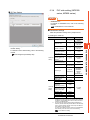
1.1
Setting the Communication Interface............................................................................................... 1 - 3
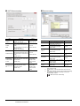
1.1.1 Setting connected equipment (Channel setting)................................................................... 1 - 3
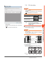
1.1.2 I/F communication setting..................................................................................................... 1 - 9
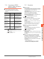
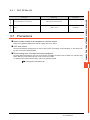
1.1.3 Precautions......................................................................................................................... 1 - 11
1.2
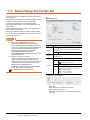
Writing the Project Data and OS onto the GOT ............................................................................. 1 - 12
1.2.1 Writing the project data and OS onto the GOT................................................................... 1 - 12
1.2.2 Checking the project data and OS writing on GOT............................................................. 1 - 13
1.3
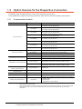
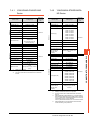
Option Devices for the Respective Connection ............................................................................. 1 - 14
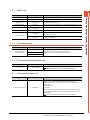
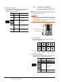
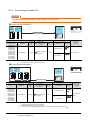
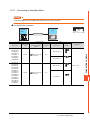
1.3.1 Communication module ...................................................................................................... 1 - 14
1.3.2 Option unit .......................................................................................................................... 1 - 15
1.3.3 Conversion cable ................................................................................................................ 1 - 15
1.3.4 Serial multi-drop connection unit ........................................................................................ 1 - 15
1.3.5 Field network adapter unit .................................................................................................. 1 - 15
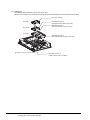
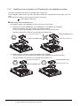
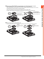
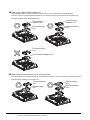
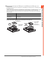
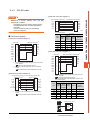
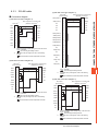
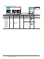
1.3.6 Installing a unit on another unit (Checking the unit installation position) ............................ 1 - 16
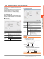
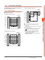
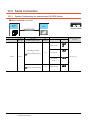
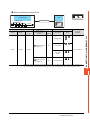
1.4
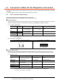
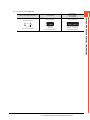
Connection Cables for the Respective Connection ....................................................................... 1 - 20
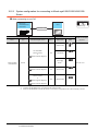
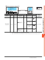
1.4.1 GOT connector specifications............................................................................................. 1 - 20
1.4.2 Coaxial cableconnector connection method ....................................................................... 1 - 22
1.4.3 Terminating resistors of GOT ............................................................................................. 1 - 23
1.5
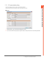
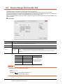
Verifying GOT Recognizes Connected Equipment........................................................................ 1 - 25
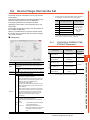
1.6
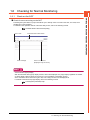
Checking for Normal Monitoring .................................................................................................... 1 - 27
1.6.1 Check on the GOT.............................................................................................................. 1 - 27
1.6.2 Confirming the communication state on the GOT side (For Ethernet connection) ............. 1 - 30
1.6.3 Confirming the communication state to each station (Station monitoring function) ............ 1 - 32
CONNECTIONS TO NON-MITSUBISHI PRODUCTS
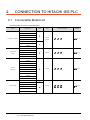
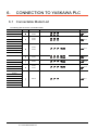
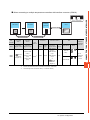
2. CONNECTION TO HITACHI IES PLC
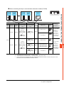
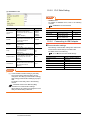
2.1
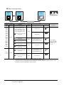
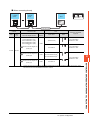
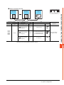
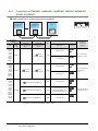
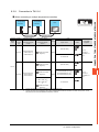
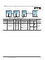
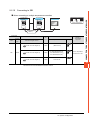
Connectable Model List ................................................................................................................... 2 - 2
2.2
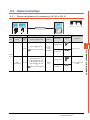
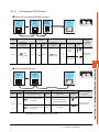
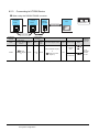
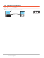
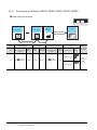
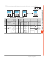
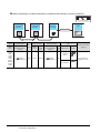
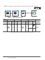
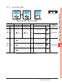
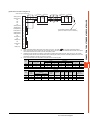
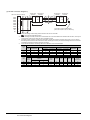
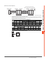
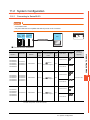
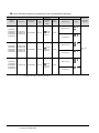
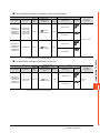
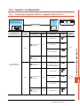
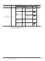
System Configuration ...................................................................................................................... 2 - 3
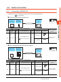
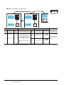
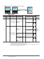
2.2.1 Connection to large-sized H series....................................................................................... 2 - 3
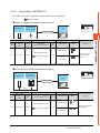
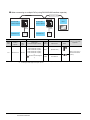
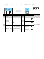
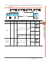
2.2.2 Connecting to H-200 to 252 series, H series board type or EH-150 series .......................... 2 - 5
A - 10
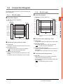
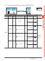
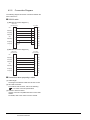
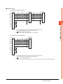
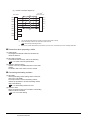
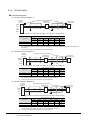
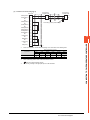
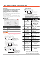
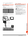
2.3
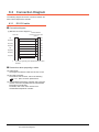
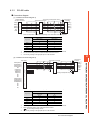
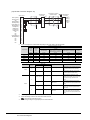
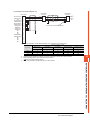
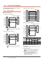
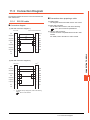
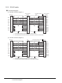
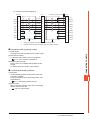
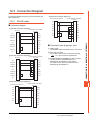
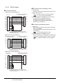
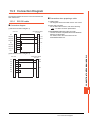
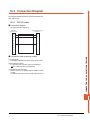
Connection Diagram ........................................................................................................................ 2 - 7
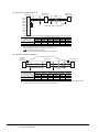
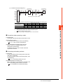
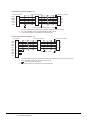
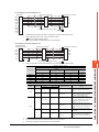
2.3.1 RS-232 cable ........................................................................................................................ 2 - 7
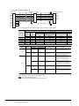
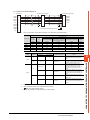
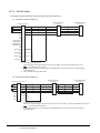
2.3.2 RS-422 cable ........................................................................................................................ 2 - 7
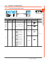
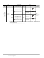
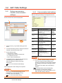
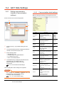
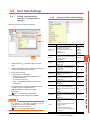
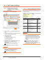
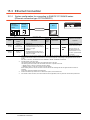
2.4
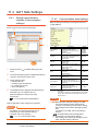
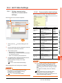
GOT Side Settings........................................................................................................................... 2 - 9
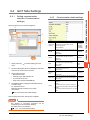
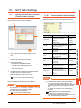
2.4.1 Setting communication interface (Communication settings)................................................. 2 - 9
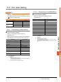
2.4.2 Communication detail settings.............................................................................................. 2 - 9
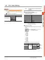
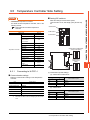
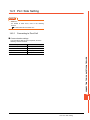
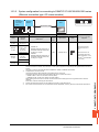
2.5
PLC Side Setting ........................................................................................................................... 2 - 11
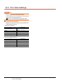
2.6
Device Range that Can Be Set...................................................................................................... 2 - 12
2.6.1 HITACHI HIDIC H Series.................................................................................................... 2 - 14
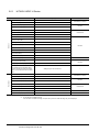
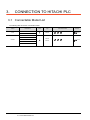
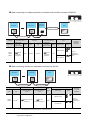
3. CONNECTION TO HITACHI PLC
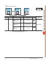
3.1
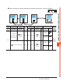
Connectable Model List ................................................................................................................... 3 - 2
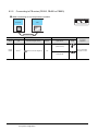
3.2
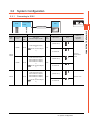
System Configuration ...................................................................................................................... 3 - 3
3.2.1 Connecting to S10V.............................................................................................................. 3 - 3
3.2.2 Connecting to S10mini ......................................................................................................... 3 - 4
3.3
Connection Diagram ........................................................................................................................ 3 - 5
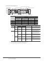
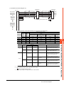
3.3.1 RS-232 cable ........................................................................................................................ 3 - 5
3.3.2 RS-422 cable ........................................................................................................................ 3 - 5
3.4
GOT Side Settings........................................................................................................................... 3 - 6
3.4.1 Setting communication interface (Communication settings)................................................. 3 - 6
3.4.2 Communication detail settings.............................................................................................. 3 - 6
3.5
PLC Side Setting ............................................................................................................................. 3 - 7
3.5.1 Connecting to communication module ................................................................................. 3 - 7
3.6
Device Range that Can Be Set........................................................................................................ 3 - 8
3.6.1 HITACHI S10mini/S10V ....................................................................................................... 3 - 8
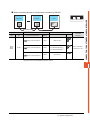
4. CONNECTION TO FUJI PLC
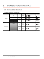
4.1
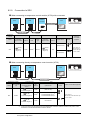
Connectable Model List ................................................................................................................... 4 - 2
4.2
Serial connection ............................................................................................................................. 4 - 3
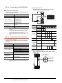
4.2.1 Connecting to MICREX-F55 ................................................................................................. 4 - 3
4.2.2 Connecting to MICREX-F70 ................................................................................................. 4 - 5
4.2.3 Connecting to MICREX-F120S/140S/15[]S .......................................................................... 4 - 8
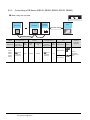
4.2.4 System Configuration for connecting to MICREX-SX SPH ................................................ 4 - 11
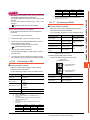
4.2.5 Connection Diagram ........................................................................................................... 4 - 12
4.2.6 GOT Side Settings.............................................................................................................. 4 - 15
4.2.7 PLC Side Setting ................................................................................................................ 4 - 17
4.2.8 Station number setting........................................................................................................ 4 - 22
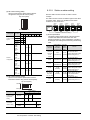
4.3
Ethernet Connection ...................................................................................................................... 4 - 23
4.3.1 System Configuration for connecting to MICREX-SX SPH ................................................ 4 - 23
4.3.2 GOT Side Settings.............................................................................................................. 4 - 24
4.3.3 PLC side setting (MICREX-SX SPH).................................................................................. 4 - 26
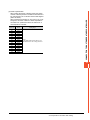
4.4
Device Range that Can Be Set...................................................................................................... 4 - 27
4.4.1 FUJI MICREX-F Series ...................................................................................................... 4 - 28
4.4.2 FUJI MICREX-SX Series .................................................................................................... 4 - 28
4.5
Precautions.................................................................................................................................... 4 - 29
A - 11
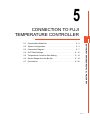
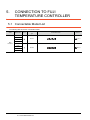
5. CONNECTION TO FUJI TEMPERATURE CONTROLLER
5.1
Connectable Model List ................................................................................................................... 5 - 2
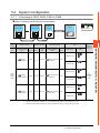
5.2
System Configuration ...................................................................................................................... 5 - 3
5.2.1 Connecting to PXR3, PXR4, PXR5 or PXR9........................................................................ 5 - 3
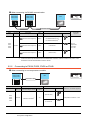
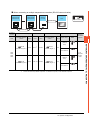
5.2.2 Connecting to PXG4, PXG5, PXG9 or PXH9 ....................................................................... 5 - 4
5.3
Connection Diagram ........................................................................................................................ 5 - 7
5.3.1 RS-232 cable ........................................................................................................................ 5 - 7
5.3.2 RS-485 cable ........................................................................................................................ 5 - 8
5.4
GOT Side Settings ......................................................................................................................... 5 - 12
5.4.1 Setting communication interface (Communication settings)............................................... 5 - 12
5.4.2 Communication detail settings............................................................................................ 5 - 12
5.5
Temperature Controller Side Setting ............................................................................................. 5 - 14
5.5.1 Connecting to PXR3/4/5/9 .................................................................................................. 5 - 14
5.5.2 Connecting to PXG4, PXG5 or PXG9................................................................................. 5 - 14
5.5.3 Connecting to PXH9 ........................................................................................................... 5 - 15
5.5.4 Connecting to interface converter (RC-77) ......................................................................... 5 - 15
5.5.5 Connecting to interface converter (SI-30A) ........................................................................ 5 - 16
5.5.6 Connecting to interface converter (KS-485) ....................................................................... 5 - 17
5.5.7 Connecting to interface converter (K3SC-10)..................................................................... 5 - 17
5.5.8 Station number setting........................................................................................................ 5 - 18
5.6
Device Range that Can Be Set ...................................................................................................... 5 - 19
5.6.1 FUJI PXR/PXG/PXH........................................................................................................... 5 - 20
5.7
Precautions .................................................................................................................................... 5 - 20
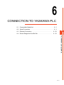
6. CONNECTION TO YASKAWA PLC
6.1
Connectable Model List ................................................................................................................... 6 - 2
6.2
Serial Connection ............................................................................................................................ 6 - 3
6.2.1 System configuration for connecting to GL120 or GL130..................................................... 6 - 3
6.2.2 System configuration for connecting to GL60S, GL60H or GL70H ...................................... 6 - 4
6.2.3 System configuration for connecting to MP-920/930, CP-9300MS/9200(H) or PROGIC-8..... 6 - 5
6.2.4 System configuration for connecting to MP-940 ................................................................... 6 - 7
6.2.5 System configuration for connecting to CP-9200SH, CP-317 .............................................. 6 - 8
6.2.6 System configuration for connecting to MP2200, MP2300 or MP2300S.............................. 6 - 9
6.2.7 Connection Diagram ........................................................................................................... 6 - 10
6.2.8 GOT Side Settings.............................................................................................................. 6 - 15
6.2.9 PLC Side Settings............................................................................................................... 6 - 17
6.3
Ethernet Connection ...................................................................................................................... 6 - 20
6.3.1 System configuration for connecting to MP-920 or MP2200 or MP2300 or MP2300S or
CP-9200SH or CP-312 or CP-317...................................................................................... 6 - 20
6.3.2 GOT Side Settings.............................................................................................................. 6 - 21
6.3.3 GOT Ethernet setting.......................................................................................................... 6 - 22
6.3.4 PLC side setting (MP2000 series, MP920 series) .............................................................. 6 - 23
6.3.5 PLC side setting (CP-9200SH series, CP-312, CP-317 series) ......................................... 6 - 28
6.3.6 Precautions......................................................................................................................... 6 - 31
6.4
Device Range that Can Be Set ...................................................................................................... 6 - 32
6.4.1 YASKAWA GL/PROGIC8 ................................................................................................... 6 - 32
6.4.2 YASKAWA CP9200SH/MP900........................................................................................... 6 - 33
6.4.3 YASKAWA CP9200 (H) ...................................................................................................... 6 - 33
A - 12
6.4.4
6.4.5
YASKAWA CP9300MS (MC compatible) ........................................................................... 6 - 33
YASKAWA MP2000/MP900/CP9200SH Series ................................................................. 6 - 34
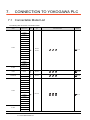
7. CONNECTION TO YOKOGAWA PLC
7.1
Connectable Model List ................................................................................................................... 7 - 2
7.2
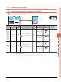
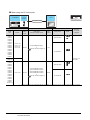
Serial Connection ............................................................................................................................ 7 - 3
7.2.1 System configuration for connecting to FA-M3/M3V ............................................................ 7 - 3
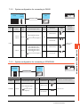
7.2.2 System configuration for connecting to FA500 ..................................................................... 7 - 5
7.2.3 System configuration for connecting to STARDOM ............................................................. 7 - 5
7.2.4 Connection diagram ............................................................................................................. 7 - 6
7.2.5 GOT side settings ................................................................................................................. 7 - 8
7.2.6 PLC side setting ................................................................................................................... 7 - 9
7.2.7 Connecting to CPU port/D-sub 9-pin conversion cable, SIO port adapter cable ................ 7 - 10
7.2.8 Connecting PC link module (F3LC01-1N, F3LC11-1N, F3LC11-2N) ................................. 7 - 10
7.2.9 Connecting PC link module (F3LC11-1F, F3LC12-1F) ...................................................... 7 - 11
7.2.10 Connecting PC link module (LC01-0N, LC02-0N) .............................................................. 7 - 12
7.2.11 Connecting to STARDOM .................................................................................................. 7 - 13
7.2.12 Precautions......................................................................................................................... 7 - 15
7.3
Ethernet Connection ...................................................................................................................... 7 - 16
7.3.1 System configuration for connecting to FA-M3/M3V .......................................................... 7 - 16
7.3.2 GOT Side Settings.............................................................................................................. 7 - 17
7.3.3 PLC side setting ................................................................................................................. 7 - 19
7.3.4 Connecting to Ethernet Interface Module (F3LE01-5T, F3LE11-0T).................................. 7 - 19
7.3.5 Connecting to Ethernet Interface Module (F3LE12-0T)...................................................... 7 - 20
7.3.6 Connecting to F3SP66, F3SP67, F3SP71-4N (built-in Ethernet interface) ........................ 7 - 21
7.3.7 Precautions......................................................................................................................... 7 - 21
7.4
Device Range that Can Be Set...................................................................................................... 7 - 22
7.4.1 YOKOGAWA FA500/FA-M3 Series.................................................................................... 7 - 23
7.4.2 YOKOGAWA STARDOM/FA-M3 Series ............................................................................ 7 - 23
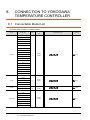
8. CONNECTION TO YOKOGAWA TEMPERATURE CONTROLLER
8.1
Connectable Model List ................................................................................................................... 8 - 2
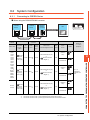
8.2
System Configuration ...................................................................................................................... 8 - 3
8.2.1 Connecting to GREEN Series .............................................................................................. 8 - 3
8.2.2 Connecting to UT100 Series ................................................................................................ 8 - 5
8.2.3 Connecting to UT2000 Series .............................................................................................. 8 - 6
8.2.4 Connecting to UTAdvanced Series ...................................................................................... 8 - 8
8.3
Connection Diagram ...................................................................................................................... 8 - 12
8.3.1 RS-232 cable ...................................................................................................................... 8 - 12
8.3.2 RS-485 cable ...................................................................................................................... 8 - 13
8.4
GOT Side Settings......................................................................................................................... 8 - 27
8.4.1 Setting communication interface (Communication settings)............................................... 8 - 27
8.4.2 Communication detail settings............................................................................................ 8 - 27
8.5
Temperature Controller Side Setting ............................................................................................. 8 - 29
8.5.1 Connecting to GREEN Series ............................................................................................ 8 - 29
8.5.2 Connecting to UT100 Series .............................................................................................. 8 - 30
8.5.3 Connecting to UT2000 Series ............................................................................................ 8 - 30
8.5.4 Connecting to UTAdvanced Series .................................................................................... 8 - 30
8.5.5 Connecting to RS232C/RS485 converter (ML2-[]) ............................................................. 8 - 31
A - 13
8.5.6
Station number setting........................................................................................................ 8 - 32
8.6
Device Range that Can Be Set ...................................................................................................... 8 - 33
8.6.1 YOKOGAWA GREEN/UT100/UT2000/UTAdvanced ......................................................... 8 - 33
8.7
Precautions .................................................................................................................................... 8 - 34
9. CONNECTION TO RKC TEMPERATURE CONTROLLER
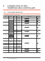
9.1
Connectable Model List ................................................................................................................... 9 - 2
9.2
System Configuration ...................................................................................................................... 9 - 4
9.2.1 Connecting to H-PCP-J ........................................................................................................ 9 - 4
9.2.2 Connecting to H-PCP-A or H-PCP-B.................................................................................... 9 - 7
9.2.3 Connecting to SRZ ............................................................................................................... 9 - 9
9.2.4 Connecting to CB Series (CB100, CB400, CB500, CB700, CB900) .................................. 9 - 12
9.2.5 Connecting to FB series (FB100, FB400 or FB900) ........................................................... 9 - 14
9.2.6 Connecting to RB Series (RB100, RB400, RB500, RB700, RB900) .................................. 9 - 18
9.2.7 Connection to PF900/901, HA400/401, HA900/901, RMC500, MA900/901, AG500,
SA100/200 .......................................................................................................................... 9 - 20
9.2.8 Connection to THV-A1........................................................................................................ 9 - 23
9.2.9 Connection to SRX ............................................................................................................. 9 - 26
9.2.10 Connecting to SB1.............................................................................................................. 9 - 27
9.2.11 Connecting to B400 ............................................................................................................ 9 - 29
9.3
Connection Diagram ...................................................................................................................... 9 - 30
9.3.1 RS-232 cable ...................................................................................................................... 9 - 30
9.3.2 RS-422 cable ...................................................................................................................... 9 - 31
9.3.3 RS-485 cable ...................................................................................................................... 9 - 33
9.4
GOT Side Settings ......................................................................................................................... 9 - 39
9.4.1 Setting communication interface (Communication settings)............................................... 9 - 39
9.4.2 Communication detail settings............................................................................................ 9 - 39
9.5
Temperature Controller Side Setting ............................................................................................. 9 - 41
9.5.1 Connecting to H-PCP-J ...................................................................................................... 9 - 41
9.5.2 Connecting to H-PCP-A, H-PCP-B ..................................................................................... 9 - 42
9.5.3 Connecting to Z-TIO, Z-DIO, Z-CT ..................................................................................... 9 - 43
9.5.4 Connecting to Z-COM......................................................................................................... 9 - 44
9.5.5 Connecting to CB Series .................................................................................................... 9 - 45
9.5.6 Connecting to FB Series..................................................................................................... 9 - 45
9.5.7 Connecting to RB Series .................................................................................................... 9 - 46
9.5.8 Connecting to PF900/900 ................................................................................................... 9 - 46
9.5.9 Connecting to HA400/401, HA900/901............................................................................... 9 - 46
9.5.10 Connecting to AG500 ......................................................................................................... 9 - 47
9.5.11 Connecting to RMC500 ...................................................................................................... 9 - 47
9.5.12 Connecting to MA900, MA901............................................................................................ 9 - 47
9.5.13 Connecting to THV-A1........................................................................................................ 9 - 47
9.5.14 Connecting to SA100/SA200 .............................................................................................. 9 - 48
9.5.15 Connecting to X-TIO Module .............................................................................................. 9 - 48
9.5.16 Connecting to SB1.............................................................................................................. 9 - 49
9.5.17 Connecting to B400 ............................................................................................................ 9 - 49
9.5.18 Station number setting........................................................................................................ 9 - 50
9.6
Device Range that Can Be Set ...................................................................................................... 9 - 52
9.6.1 RKC SR Mini HG ................................................................................................................ 9 - 53
9.7
Precautions .................................................................................................................................... 9 - 53
A - 14
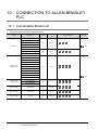
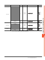
10. CONNECTION TO ALLEN-BRADLEY PLC
10.1
Connectable Model List ................................................................................................................. 10 - 2
10.2
Serial Connection .......................................................................................................................... 10 - 4
10.2.1 System Configuration for connecting to SLC500 Series .................................................... 10 - 4
10.2.2 System configuration for connecting to MicroLogix1000/1200/1400/1500 Series .............. 10 - 6
10.2.3 System Configuration for connecting to Control/Compact/FlexLogix Series ...................... 10 - 8
10.2.4 Connection Diagram ........................................................................................................... 10 - 9
10.2.5 GOT Side Settings............................................................................................................ 10 - 11
10.2.6 PLC Side Setting .............................................................................................................. 10 - 13
10.3
Ethernet Connection .................................................................................................................... 10 - 14
10.3.1 System configuration for connecting to ControlLogix or CompactLogix
(Ethernet connection type: EtherNet/IP (AB))................................................................... 10 - 14
10.3.2 System configuration for connecting to ControlLogix, CompactLogix or FlexLogix
(Ethernet connection type: EtherNet/IP (AB Tag)) ........................................................... 10 - 15
10.3.3 GOT Side Settings............................................................................................................ 10 - 16
10.3.4 PLC side setting ............................................................................................................... 10 - 19
10.3.5 Precautions....................................................................................................................... 10 - 19
10.4
Device Range that Can Be Set.................................................................................................... 10 - 20
10.4.1 AB SLC500 ....................................................................................................................... 10 - 22
10.4.2 AB MicroLogix Series ....................................................................................................... 10 - 22
10.4.3 AB MicroLogix Series (Device extended) ......................................................................... 10 - 23
10.4.4 AB Control/CompactLogix ................................................................................................ 10 - 23
10.4.5 AB Control/CompactLogix (Tag)....................................................................................... 10 - 23
11. CONNECTION TO GE PLC
11.1
Connectable Model List ................................................................................................................. 11 - 2
11.2
System Configuration .................................................................................................................... 11 - 3
11.2.1 Connecting to Series90-30 ................................................................................................. 11 - 3
11.2.2 Connecting to Series90-70 ................................................................................................. 11 - 6
11.2.3 Connecting to VersaMax Micro .......................................................................................... 11 - 7
11.3
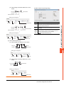
Connection Diagram ...................................................................................................................... 11 - 9
11.3.1 RS-232 cable ...................................................................................................................... 11 - 9
11.3.2 RS-422 cable .................................................................................................................... 11 - 10
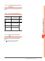
11.4
GOT Side Settings....................................................................................................................... 11 - 12
11.4.1 Setting communication interface (Communication settings)............................................. 11 - 12
11.4.2 Communication detail settings.......................................................................................... 11 - 12
11.5
PLC Side Setting ......................................................................................................................... 11 - 13
11.5.1 Connecting to Series 90-30 .............................................................................................. 11 - 13
11.5.2 Connecting to VersaMaxMicro ......................................................................................... 11 - 13
11.5.3 Connecting to IC693CMM311 .......................................................................................... 11 - 14
11.5.4 Connecting to IC697CMM711 .......................................................................................... 11 - 14
11.5.5 Station number setting...................................................................................................... 11 - 14
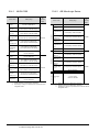
11.6
Device Range that Can Be Set.................................................................................................... 11 - 15
11.6.1 GE Series 90 .................................................................................................................... 11 - 15
11.7
Precautions.................................................................................................................................. 11 - 15
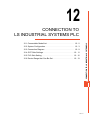
12. CONNECTION TO LS INDUSTRIAL SYSTEMS PLC
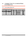
12.1
Connectable Model List ................................................................................................................. 12 - 2
A - 15
12.2
System Configuration .................................................................................................................... 12 - 3
12.2.1 Connecting to K80S or K120S............................................................................................ 12 - 3
12.2.2 Connecting to K200S.......................................................................................................... 12 - 5
12.2.3 Connecting to K300S.......................................................................................................... 12 - 7
12.3
Connection Diagram ...................................................................................................................... 12 - 9
12.3.1 RS-232 cable ...................................................................................................................... 12 - 9
12.3.2 RS-422 cable .................................................................................................................... 12 - 10
12.4
GOT Side Settings ....................................................................................................................... 12 - 11
12.4.1 Setting communication interface (Communication settings)............................................. 12 - 11
12.4.2 Communication detail settings.......................................................................................... 12 - 11
12.5
PLC Side Setting ......................................................................................................................... 12 - 12
12.5.1 Connecting to PLC CPU ................................................................................................... 12 - 12
12.5.2 Connecting to Cnet I/F module ......................................................................................... 12 - 12
12.6
Device Range that Can Be Set .................................................................................................... 12 - 13
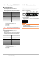
12.6.1 LS Industrial Systems MASTER-K ................................................................................... 12 - 13
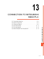
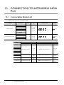
13. CONNECTION TO MITSUBISHI INDIA PLC
13.1
Connectable Model List ................................................................................................................. 13 - 2
13.2
System Configuration .................................................................................................................... 13 - 3
13.2.1 Connecting to Nexgenie 1000 PLC, Nexgenie 2000 PLUS PLC........................................ 13 - 3
13.3
Connection Diagram ...................................................................................................................... 13 - 5
13.3.1 RS-232 cable ...................................................................................................................... 13 - 5
13.3.2 RS-422 cable ...................................................................................................................... 13 - 6
13.3.3 RS-485 cable ...................................................................................................................... 13 - 8
13.4
GOT Side Settings ....................................................................................................................... 13 - 11
13.4.1 Setting communication interface (Communication settings)............................................. 13 - 11
13.4.2 Communication detail settings.......................................................................................... 13 - 11
13.5
PLC Side Settings........................................................................................................................ 13 - 12
13.6
DEVICE RANGE THAT CAN BE SET ......................................................................................... 13 - 13
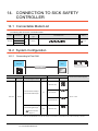
14. CONNECTION TO SICK SAFETY CONTROLLER
14.1
Connectable Model List ................................................................................................................. 14 - 2
14.2
System Configuration .................................................................................................................... 14 - 2
14.2.1 Connecting to Flexi Soft...................................................................................................... 14 - 2
14.3
Connection Diagram ...................................................................................................................... 14 - 3
14.3.1 RS-232 cable ...................................................................................................................... 14 - 3
14.4
GOT Side Settings ......................................................................................................................... 14 - 4
14.4.1 Setting communication interface (Communication settings)............................................... 14 - 4
14.4.2 Communication detail settings............................................................................................ 14 - 4
14.5
PLC Side Setting ........................................................................................................................... 14 - 5
14.5.1 Connecting to Flexi Soft...................................................................................................... 14 - 5
14.6
Device Range That Can Be Set..................................................................................................... 14 - 6
14.6.1 SICK Safety Controller (SICK Flexi Soft)............................................................................ 14 - 7
15. CONNECTION TO SIEMENS PLC
15.1
A - 16
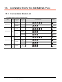
Connectable Model List ................................................................................................................. 15 - 2
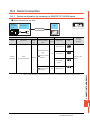
15.2
Serial Connection .......................................................................................................................... 15 - 3
15.2.1 System configuration for connecting to SIMATIC S7-300/400 series................................. 15 - 3
15.2.2 System configuration for connecting to SIMATIC S7-200 .................................................. 15 - 5
15.2.3 Connection Diagram ........................................................................................................... 15 - 6
15.2.4 GOT Side Settings.............................................................................................................. 15 - 7
15.2.5 PLC Side Setting ................................................................................................................ 15 - 8
15.2.6 Connecting to HMI Adapter ................................................................................................ 15 - 8
15.2.7 Connecting to SIMATIC S7-200 ......................................................................................... 15 - 9
15.2.8 Precautions......................................................................................................................... 15 - 9
15.3
Ethernet Connection .................................................................................................................... 15 - 10
15.3.1 System configuration for connecting to SIMATIC S7-300/400 series
(Ethernet connection type: FETCH/WRITE) ..................................................................... 15 - 10
15.3.2 System configuration for connecting to SIMATIC S7-200/300/400/1200 series
(Ethernet connection type: OP communication) ............................................................... 15 - 11
15.3.3 GOT Side Settings............................................................................................................ 15 - 12
15.3.4 PLC side setting ............................................................................................................... 15 - 15
15.3.5 Precautions....................................................................................................................... 15 - 16
15.4
Device Range that Can Be Set.................................................................................................... 15 - 17
15.4.1 SIEMENS S7-300/400 Series........................................................................................... 15 - 19
15.4.2 SIEMENS S7-200 Series.................................................................................................. 15 - 19
15.4.3 SIEMENS S7 (Ethernet) ................................................................................................... 15 - 19
15.4.4 SIEMENS OP (Ethernet) .................................................................................................. 15 - 19
REVISIONS
WARRANTY
A - 17
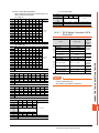
List of Manuals for GT Works3
For the manuals related to this product, install the manuals with the drawing software.
If you need a printed manual, consult your local Mitsubishi representative or branch office.
■1. List of Manuals for GT Designer3(GOT2000)
(1) Screen drawing software manuals
Manual name
GT Works3 Version1 Installation Procedure Manual
GT Designer3 (GOT2000) Help
Manual number
(Model code)
-
GT Converter2 Version3 Operating Manual for GT Works3
SH-080862ENG
(1D7MB2)
GOT2000 Series MES Interface Function Manual for GT Works3 Version1
SH-081228ENG
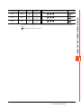
(2) Connection manuals
Manual name
Manual number
(Model code)
GOT2000 Series Connection Manual (Mitsubishi Products) For GT Works3 Version1
SH-081197ENG
(1D7MJ8)
GOT2000 Series Connection Manual (Non-Mitsubishi Products 1) For GT Works3 Version1
SH-081198ENG
GOT2000 Series Connection Manual (Non-Mitsubishi Products 2) For GT Works3 Version1
SH-081199ENG
GOT2000 Series Connection Manual (Microcomputers, MODBUS/Fieldbus Products, Peripherals) For GT Works3
Version1
SH-081200ENG
(3) GT SoftGOT2000 manuals
Manual name
GT SoftGOT2000 Version1 Operating Manual
Manual number
(Model code)
SH-081201ENG
(4) GOT2000 manuals
Manual name
A - 18
Manual number
(Model code)
GOT2000 Series User's Manual (Hardware)
SH-081194ENG
(1D7MJ5)
GOT2000 Series User's Manual (Utility)
SH-081195ENG
(1D7MJ6)
GOT2000 Series User's Manual (Monitor)
SH-081196ENG
(1D7MJ7)
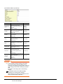
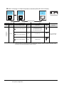
Abbreviations, Generic Terms, the meaning of the icon
The following shows the abbreviations and generic terms used in Help.
■1. GOT
Meaning of icon
Abbreviations and generic terms
GT27-X
GT2715-XTBA, GT2715-XTBD
GT2712-S
GT2712-STBA, GT2712-STWA, GT2712-STBD, GT2712-STWD
GT2710-S
GT2710-STBA, GT2710-STBD
GT27-V
GT2710-V
GT2710-VTBA, GT2710-VTWA, GT2710-VTBD, GT2710-VTWD
GT27-S
GT2708-S
GT2708-STBA, GT2708-STBD
GT27-V
GT25-S
GT25
GT25-V
GT23
GT23-V
GT2708-V
GT2708-VTBA, GT2708-VTBD
GT2705-V
GT2705-VTBD
GT2512-S
GT2512-STBA, GT2512-STBD
GT2510-V
GT2510-VTBA, GT2510-VTWA, GT2510-VTBD, GT2510-VTWD
GT2508-V
GT2508-VTBA, GT2508-VTWA, GT2508-VTBD, GT2508-VTWD
GT2310-V
GT2310-VTBA, GT2310-VTBD
GT2308-V
GT2308-VTBA, GT2308-VTBD
GOT2000
Series
GT21-R
GT2104-R
Not
support
Support
GT2715-X
GT27-S
GT27
Description
-
-
GT21
-
GT2104-RTBD
-
GT2103-PMBD
-
GT2103-PMBDS
-
GT2103-PMBDS2
-
GT2103-PMBLS
-
GT SoftGOT2000 Version1
-
GT21
GT21-P
GT2103-P
GT SoftGOT2000
GOT1000 Series
GOT1000 Series
-
GOT900 Series
GOT-A900 Series, GOT-F900 Series
-
GOT800 Series
GOT-800 Series
-
■2. Communication unit
Abbreviations and generic terms
Description
Bus connection unit
GT15-QBUS, GT15-QBUS2, GT15-ABUS, GT15-ABUS2, GT15-75QBUSL,
GT15-75QBUS2L, GT15-75ABUSL, GT15-75ABUS2L
Serial communication unit
GT15-RS2-9P, GT15-RS4-9S, GT15-RS4-TE
MELSECNET/H communication unit
GT15-J71LP23-25, GT15-J71BR13
CC-Link IE Controller Network communication unit
GT15-J71GP23-SX
CC-Link IE Field Network communication unit
GT15-J71GF13-T2
CC-Link communication unit
GT15-J61BT13
Wireless LAN communication unit
GT25-WLAN
Serial multi-drop connection unit
GT01-RS4-M
Connection conversion adapter
GT10-9PT5S
Field network adapter unit
GT25-FNADP
A - 19
■3. Option unit
Abbreviations and generic terms
Printer unit
Description
GT15-PRN
Video/RGB unit
Video input unit
GT27-V4-Z (A set of GT16M-V4-Z and GT27-IF1000)
RGB input unit
GT27-R2, GT27-R2-Z (A set of GT16M-R2-Z and GT27-IF1000)
Video/RGB input unit
GT27-V4R1-Z (A set of GT16M-V4R1-Z and GT27-IF1000)
RGB output unit
GT27-ROUT, GT27-ROUT-Z (A set of GT16M-ROUT-Z and GT27-IF1000)
Multimedia unit
GT27-MMR-Z (A set of GT16M-MMR-Z and GT27-IF1000)
Video signal conversion unit
GT27-IF1000
External I/O unit
GT15-DIO, GT15-DIOR
Sound output unit
GT15-SOUT
■4. Option
Abbreviations and generic terms
Description
SD card
NZ1MEM-2GBSD, NZ1MEM-4GBSD, NZ1MEM-8GBSD, NZ1MEM-16GBSD,
L1MEM-2GBSD, L1MEM-4GBSD
Battery
GT11-50BAT
Protective sheet
GT27-15PSGC, GT25-12PSGC, GT25-10PSGC, GT25-08PSGC, GT2505PSGC, GT21-04RPSGC-UC, GT21-03PSGC-UC, GT27-15PSCC, GT2512PSCC, GT25-10PSCC, GT25-08PSCC, GT25- 12PSCC-UC, GT2510PSCC-UC, GT25-08PSCC-UC, GT25-05PSCC, GT21-04RPSCC-UC,
GT21-03PSCC-UC
Protective cover for oil
GT20-15PCO, GT20-12PCO, GT20-10PCO, GT20-08PCO, GT25-05PCO,
GT10-20PCO
USB environmental protection cover
GT25-UCOV, GT25-05UCOV
Stand
GT15-90STAND, GT15-80STAND, GT15-70STAND, GT15-60STAND
Attachment
GT15-70ATT-98, GT15-70ATT-87, GT15-60ATT-97, GT15-60ATT-96, GT1560ATT-87, GT15-60ATT-77
■5. Software
(1) Software related to GOT
Abbreviations and generic terms
GT Works3
SW1DND-GTWK3-J, SW1DND-GTWK3-E, SW1DND-GTWK3-C
GT Designer3 Version1
Screen drawing software GT Designer3 for GOT2000/GOT1000 series
GT Designer3
GT Designer3 (GOT2000)
A - 20
Description
Screen drawing software for GOT2000 series included in GT Works3
GT Designer3 (GOT1000)
Screen drawing software for GOT1000 series included in GT Works3
GT Simulator3
Screen simulator GT Simulator3 for GOT2000/GOT1000/GOT900 series
GT SoftGOT2000
Monitoring software GT SoftGOT2000 series
GT Converter2
Data conversion software GT Converter2 for GOT1000/GOT900 series
GT Designer2 Classic
Screen drawing software GT Designer2 Classic for GOT900 series
GT Designer2
Screen drawing software GT Designer2 for GOT1000/GOT900 series
DU/WIN
Screen drawing software FX-PCS-DU/WIN for GOT-F900 series
(2) Software related to iQ Works
Abbreviations and generic terms
Description
iQ Works
Abbreviation of iQ Platform compatible engineering environment MELSOFT
iQ Works
MELSOFT Navigator
Generic term for integrated development environment software included in the
SW DNC-IQWK (iQ Platform compatible engineering environment MELSOFT
iQ Works)
(□ indicates a version.)
(3) Other software
Abbreviations and generic terms
Description
GX Works3
SW□DND-GXW3-E (-EA) type programmable controller engineering software
(□ indicates a version.)
GX Works2
SW□DNC-GXW2-□ type programmable controller engineering software
(□ indicates a version.)
GX Simulator3
Simulation function of GX Works3
GX Simulator2
Simulation function of GX Works2
GX Simulator
SW□D5C-LLT-E (-EV) type ladder logic test tool function software package
(SW5D5C-LLT (-V) or later versions)
(□ indicates a version.)
Controller simulator
GX Developer
SW□D5C-GPPW-E (-EV)/SW□D5F-GPPW (-V) type software package
(□ indicates a version.)
GX LogViewer
SW□DNN-VIEWER-E type software package
(□ indicates a version.)
PX Developer
SW□D5C-FBDQ-E type FBD software package for process control
(□ indicates a version.)
MT Works2
Motion controller engineering environment MELSOFT MT Works2
(SW□DND-MTW2-E)
(□ indicates a version.)
MT Developer
SW□RNC-GSV type integrated start-up support software for motion controller
Q series
(□ indicates a version.)
CW Configurator
C Controller module configuration and monitor tool (SW1DND-RCCPU-E)
(□ indicates a version.)
MR Configurator2
SW□DNC-MRC2-E type servo configuration software
(□ indicates a version.)
MR Configurator
MRZJW□-SETUP type servo configuration software
(□ indicates a version.)
FR Configurator
Inverter setup software (FR-SW□-SETUP-WE)
(□ indicates a version.)
NC Configurator2
CNC parameter setting support tool (FCSB1221)
NC Configurator
CNC parameter setting support tool
FX Configurator-FP
Parameter setting, monitoring, and testing software packages for FX3U20SSC-H (SW□D5CFXSSCE)
(□ indicates a version.)
FX3U-ENET-L Configuration tool
FX3U-ENET-L type Ethernet module setting software (SW1D5-FXENETL-E)
RT ToolBox2
Robot program creation software (3D-11C-WINE)
MX Component
MX Component Version□ (SW□D5C-ACT-E, SW□D5C-ACT-EA)
(□ indicates a version.)
MX Sheet
MX Sheet Version□ (SW□D5C-SHEET-E, SW□D5C-SHEET-EA)
(□ indicates a version.)
CPU Module Logging Configuration Tool
CPU module logging configuration tool (SW1DNN-LLUTL-E)
■6. License key (for GT SoftGOT2000)
Abbreviations and generic terms
License key
Description
GT27-SGTKEY-U
A - 21
■7. Others
Abbreviations and generic terms
A - 22
Description
IAI
IAI Corporation
AZBIL
Azbil Corporation
OMRON
OMRON Corporation
KEYENCE
KEYENCE CORPORATION
KOYO EI
KOYO ELECTRONICS INDUSTRIES CO., LTD.
JTEKT
JTEKT Corporation
SHARP
Sharp Manufacturing Systems Corporation
SHINKO
Shinko Technos Co., Ltd.
CHINO
CHINO CORPORATION
TOSHIBA
TOSHIBA CORPORATION
TOSHIBA MACHINE
TOSHIBA MACHINE CO., LTD.
PANASONIC
Panasonic Corporation
PANASONIC IDS
Panasonic Industrial Devices SUNX Co., Ltd.
HITACHI IES
Hitachi Industrial Equipment Systems Co., Ltd.
HITACHI
Hitachi, Ltd.
FUJI
FUJI ELECTRIC CO., LTD.
YASKAWA
YASKAWA Electric Corporation
YOKOGAWA
Yokogawa Electric Corporation
RKC
RKC INSTRUMENT INC.
ALLEN-BRADLEY
Allen-Bradley products manufactured by Rockwell Automation, Inc.
GE
GE Intelligent Platforms, Inc.
HMS
HMS Industrial Networks
LS IS
LS Industrial Systems Co., Ltd.
MITSUBISHI INDIA
Mitsubishi Electric India Pvt. Ltd.
ODVA
Open DeviceNet Vendor Association, Inc.
SCHNEIDER
Schneider Electric SA
SICK
SICK AG
SIEMENS
Siemens AG
PLC
Programmable controller manufactured by each corporation
Control equipment
Control equipment manufactured by each corporation
Temperature controller
Temperature controller manufactured by each corporation
Indicating controller
Indicating controller manufactured by each corporation
Controller
Controller manufactured by each corporation
1
PREPARATORY PROCEDURES FOR MONITORING
1.
1
PREPARATORY PROCEDURES
FOR MONITORING
1.1 Setting the Communication Interface . . . . . . . . . . . . . . . . . . 1 - 3
1.2 Writing the Project Data and OS onto the GOT . . . . . . . . . 1 - 12
1.3 Option Devices for the Respective Connection . . . . . . . . . 1 - 14
1.4 Connection Cables for the Respective Connection . . . . . . 1 - 20
1.5 Verifying GOT Recognizes Connected Equipment . . . . . . 1 - 25
1.6 Checking for Normal Monitoring. . . . . . . . . . . . . . . . . . . . . 1 - 27
1-1
1.
PREPARATORY PROCEDURES FOR
MONITORING
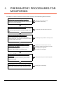
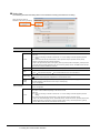
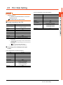
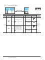
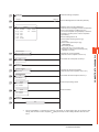
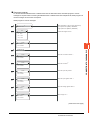
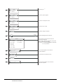
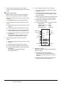
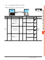
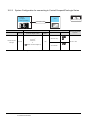
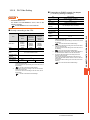
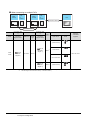
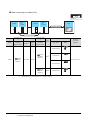
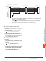
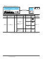
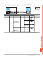
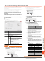
The following shows the procedures to be taken before monitoring and corresponding reference sections.
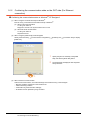
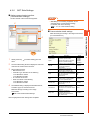
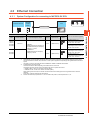
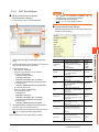
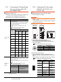
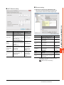
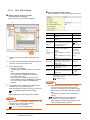
Setting the communication interface
Determine the connection type and channel No. to be used, and
perform the communication setting.
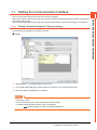
1.1Setting the Communication Interface
Each chapter GOT Side Settings
Writing the project data and OS
Write the standard monitor OS, communication driver, extended
function OS, project data and communication settings onto the
1.2.1Writing the project data and OS onto the GOT
GOT.
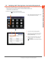
Verifying the project data and OS
Verify the standard monitor OS, communication driver,
extended function OS, project data and communication settings
1.2.2Checking the project data and OS writing on GOT
are properly written onto the GOT.
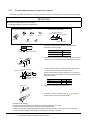
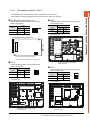
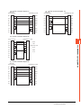
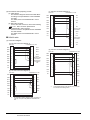
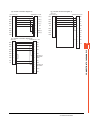
Attaching the communication unit and
connecting the cable
1.3Option Devices for the Respective Connection
Mount the optional equipment and prepare/connect the
Each chapter System Configuration
connection cable according to the connection type.
Each chapter Connection Diagram
Verifying GOT recognizes connected
equipment
1.4Connection Cables for the Respective Connection
1.5Verifying GOT Recognizes Connected Equipment
Verify the GOT recognizes controllers on [Communication
Settings] of the Utility.
Verifying the GOT is monitoring normally
Verify the GOT is monitoring normally using Utility, Developer,
1.6Checking for Normal Monitoring
etc.
1-2
1. PREPARATORY PROCEDURES FOR MONITORING
1.1 Setting the Communication Interface
Set the communication interface of GOT and the connected equipment.
When using the GOT at the first time, make sure to set the channel of communication interface and the communication
driver before writing to GOT.
Set the communication interface of the GOT at [Controller Setting] and [I/F Communication Setting] in GT Designer3.
1.1.1
Setting connected equipment (Channel setting)
Set the channel of the equipment connected to the GOT.
Setting
1.
Select [Common]
2.
The Controller Setting dialog box appears. Select the channel No. to be used from the list menu.
3.
Refer to the following explanations for the setting.
[Controller Setting] from the menu.
POINT
Channel No.2 to No.4
Use the channel No.2 to No.4 when using the Multi-channel function.
For details of the Multi-channel function, refer to the following.
Mitsubishi Products 20. MULTI-CHANNEL FUNCTION
1. PREPARATORY PROCEDURES FOR MONITORING
1.1 Setting the Communication Interface
1-3
PREPARATORY PROCEDURES FOR MONITORING
1
Setting item
This section describes the setting items of the Manufacturer, Controller Type, Driver and I/F.
When using the channel No.2 to No.4, put a check mark at [Use CH*].
Item
Description
Use CH*
Select this item when setting the channel No.2 to No.4.
Manufacturer
Select the manufacturer of the equipment to be connected to the GOT.
Select the type of the equipment to be connected to the GOT. For the settings, refer to the following.
Type
(2)Setting [Controller Type]
Select the interface of the GOT to which the equipment is connected. For the settings, refer to the following.
I/F
(3)Setting [I/F]
Select the communication driver to be written to the GOT. For the settings, refer to the following.
Driver
(1)Setting [Driver]
Make settings for the transmission speed and data length of the communication driver.
Detail Setting
Refer to each chapter of the equipment to be connected to the GOT.
(1) Setting [Driver]
The displayed items for a driver differ according to the settings [Manufacturer], [Controller Type] and [I/F].
When the driver to be set is not displayed, confirm if [Manufacturer], [Controller Type] and [I/F] are correct.
For the settings, refer to the following.
[Setting the communication interface] section in each chapter
1-4
1. PREPARATORY PROCEDURES FOR MONITORING
1.1 Setting the Communication Interface
1
(2) Setting [Controller Type]
The types for the selection differ depending on the PLC to be used.
For the settings, refer to the following.
Model name
PXG4
H-302
H-702
FUJI PXR/PXG/PXH
H-1002
GL120
H-300
YASKAWA GL/PROGIC8
H-2000
MP920
H-252
YASKAWA CP-9200SH/MP-900 Series
H-252C
H-28DR
CP-9200(H)
YASKAWA CP-9300MS (MC compatible)
CP-9300MS
MP2200
MP2300
H-20DT
MP920
H-28DT
YASKAWA MP2000/MP900/CP9200SH Series
H-64DT
CP-317
EH-CPU104
FA500
EH-CPU208
F3SP05
EH-CPU308
F3SP08
EH-CPU316
F3SP10
LQP510
F3SP20
LQP520
F3SP30
LQP800
F3FP36
LQP000
F3SP21
LQP010
F55
F70
FUJI MICREX-F Series
F120S
F140S
F15□S
SPH200
FUJI MICREX-SX SPH
SPH300
MP940
CP-312
HL-64DR
LQP120
MP930
CP-9200SH
HL-40DR
LQP011
MP940
YASKAWA CP-9200 (H)
H-64DR
HITACHI S10mini/S10V
MP930
CP-9200SH
H-40DR
H-40DT
GL60S
GL70H
H-250
H-20DR
GL130
GL60H
H-200
HITACHI HIDIC H Series
PXG9
PROGIC-8
H-4010
H-252B
PXG5
PXH9
H-2002
H-700
Model name
PREPARATORY PROCEDURES FOR MONITORING
Type
Type
YOKOGAWA FA500/FA-M3 Series
F3SP25
F3SP35
F3SP28
F3SP38
F3SP53
F3SP58
F3SP59
F3SP66
F3SP67
F3SP76-7S
SPH2000
SPH3000
PXR3
FUJI PXR/PXG/PXH
PXR4
PXR5
PXR9
1. PREPARATORY PROCEDURES FOR MONITORING
1.1 Setting the Communication Interface
1-5
Type
Model name
UT35A
NFJT100
UT52A
F3SP08
YOKOGAWA GREEN/UT100/UT2000 /
UTAdvanced Series
UP35A
UP55A
F3SP20
UM33A
F3SP30
H-PCP-J
F3FP36
H-PCP-A
F3SP21
H-PCP-B
F3SP25
Z-TIO
F3SP35
Z-DIO
F3SP28
Z-CT
F3SP38
CB100
F3SP53
CB400
F3SP58
CB500
F3SP59
CB700
F3SP66
CB900
F3SP67
FB100
F3SP76-7S
FB400
UT320
FB900
UT321
RB100
RKC SR Mini HG
RB400
UT351
RB500
UT420
RB700
UT450
RB900
UT520
PF900
UT550
PF901
UT551
HA400/401
UT750
HA900/901
UP350
RMC500
UP351
MA900
UP550
MA901
UP750
AG500
UM330
THV-A1
UM331
SA100
UM350
SA200
UM351
X-TIO
US1000
SLC500-20
UT130
SLC500-30
UT150
SLC500-40
UT152
UT155
AB SLC500
SLC5/01
SLC5/02
UP150
SLC5/03
UT2400
SLC5/04
UT2800
SLC5/05
UT32A
1-6
UT55A
F3SP10
UT350
YOKOGAWA GREEN/UT100/UT2000 /
UTAdvanced Series
Model name
NFCP100
F3SP05
YOKOGAWA STARDOM/FA-M3 Series
Type
1. PREPARATORY PROCEDURES FOR MONITORING
1.1 Setting the Communication Interface
Model name
1761-L10BWA
1761-L10BWB
AB MicroLogix1000/1200/1500 Series
IC693CPU311
IC693CPU313
1761-L16BWB
IC693CPU323
1761-L16BBB
IC693CPU350
1761-L32AWA
IC693CPU360
1761-L32BWA
IC693CPU363
1761-L32BWB
IC693CPU366
1761-L32BBB
IC693CPU367
1761-L32AAA
IC693CPU374
1761-L20AWA-5A
IC697CPU731
1761-L20BWA-5A
IC697CPX772
1761-L20BWB-5A
IC697CPX782
1762-L24BWA
IC697CPX928
1764-LSP
IC697CPX935
1756-L
IC697CPU780
1756-L1M1
IC697CGR772
1756-L1M2
IC697CGR935
1756-L1M3
IC697CPU788
1756-L61
IC697CPU789
1756-L62
IC697CPM790
GE Series 90
IC200UAA003
IC200UAL004
1756-L55M13
IC200UAL005
1756-L55M14
IC200UAL006
1756-L55M16
IC200UAA007
1756-L55M22
IC200UAR028
1756-L55M23
IC200UDD110
1756-L55M24
IC200UDD120
1769-L31
IC200UDD212
1769-L32E
IC200UDR005
1769-L32C
IC200UDR006
1769-L35E
IC200UDR010
1769-L35CR
IC200UDD064
1794-L33
IC200UDD164
1794-L34
IC200UDR164
1756-L
IC200UDR064
1756-L1M1
IC200UAR014
1756-L1M2
IC200UDD104
1756-L1M3
IC200UDD112
1756-L61
IC200UDR001
1756-L62
IC200UDR002
1756-L63
IC200UDR003
1756-L55M12
K7M-D□□□S(/DC)
1756-L55M13
1756-L55M14
LS Industrial Systems MASTER-K
1756-L55M16
1756-L55M23
1769-L35E
K3P-07□S
FX3-CPU000000
SICK Flexi Soft
1756-L55M24
1769-L32E
K7M-D□□□U
K4P-15AS
1756-L55M22
FX3-CPU130002
FX3-CPU320002
SIEMENS S7-300/400 Series
SIEMENS S7-200
1
1794-L34
1761-L16BWA
1756-L55M12
AB Control/CompactLogix (Tag)
AB Control/CompactLogix (Tag)
Model name
1794-L33
1761-L16AWA
1756-L63
AB Control/CompactLogix
Type
PREPARATORY PROCEDURES FOR MONITORING
Type
SIMATIC S7-300
SIMATIC S7-400
SIMATIC S7-200
1. PREPARATORY PROCEDURES FOR MONITORING
1.1 Setting the Communication Interface
1-7
(3) Setting [I/F]
The interface differs depending on the GOT to be used.
Set the I/F according to the connection and the position of communication unit to be mounted onto the GOT.
Extension interface
3rd stage
Standard interface 4
(Ethernet interface built in the GOT)
Standard interface 1
(RS-232 interface built in the GOT)
2nd stage
1st stage
Standard interface 3
(RS-422/485 interface built in the GOT)
(Example: In the case of the GT27)
1-8
Standard interface 2
(USB interface built in the GOT)
1. PREPARATORY PROCEDURES FOR MONITORING
1.1 Setting the Communication Interface
1.1.2
I/F communication setting
1
PREPARATORY PROCEDURES FOR MONITORING
This function displays the list of the GOT communication interfaces.
Set the channel and the communication driver to the interface to be used.
Setting
1.
Select [Common]
2.
The I/F Communication Setting dialog box appears. Make the settings with reference to the following explanation.
[I/F Communication Setting] from the menu.
1. PREPARATORY PROCEDURES FOR MONITORING
1.1 Setting the Communication Interface
1-9
Setting item
The following describes the setting items for the standard I/F setting and extension I/F setting.
When the GT21 series is
selected in the GOT type setting
Item
Description
Standard I/F Setting
CH No.
Set the CH No. according to the intended purpose.
0: Not used
1 to 4: Used for connecting a controller of channel No. 1 to 4 set in Setting connected equipment (Channel
setting)
5 to 8: Used for barcode function, RFID function, remote personal computer operation function (serial)
9: Used for connecting Host (PC), Ethernet download
A: Used for the report function (with a serial printer), hard copy function (with a serial printer), remote personal
computer operation function (Ethernet), VNC server function, gateway function, and MES interface function.
Multi: Used for multi-channel Ethernet connection
I/F
The communication type of the GOT standard interface is displayed.
Driver
Detail Setting
RS232
Setting
Set the driver for the device to be connected.
None
Host (Personal computer)
Each communication driver for connected devices
Make settings for the transmission speed and data length of the communication driver.
Refer to each chapter of the equipment to be connected to the GOT.
To validate the 5V power supply function in RS232, mark the [Enable the 5V power supply] checkbox.
The RS232 setting is invalid when the CH No. of [I/F-1: RS232] is [9].
GT21 is not supported.
Set the communication unit attached to the extension interface of the GOT.
GT21 is not supported.
Extend I/F Setting
CH No.
1 - 10
Set channel No. and drivers to the GOT standard interfaces.
Set the CH No. according to the intended purpose.
The number of channels differs depending on the GOT to be used.
0: Not used
1 to 4: Used for connecting a controller of channel No. 1 to 4 set in Setting connected equipment (Channel
setting)
5 to 8: Used for barcode function, RFID function, remote personal computer operation (serial)
A: Used for the video/RGB display function, multimedia function, external I/O function, operation panel function,
RGB output function, report function, hard copy function (with a printer), sound output function, gateway
function, MES interface function, and wireless LAN connection.
1. PREPARATORY PROCEDURES FOR MONITORING
1.1 Setting the Communication Interface
1
POINT
(1) Channel No.2 to No.4
Use the channel No.2 to No.4 when using the Multi-channel function.
For details of the Multi-channel function, refer to the following.
Mitsubishi Products 20. MULTI-CHANNEL FUNCTION
(2) Drivers
The displayed items for a driver differ according to the settings [Manufacturer], [Controller Type] and [I/F].
When the driver to be set is not displayed, confirm if [Manufacturer], [Controller Type] and [I/F] are correct.
[Setting the communication interface] section in each chapter
1.1.3
Precautions
Precautions for changing model
(1) When devices that cannot be converted are included.
When setting of [Manufacturer] or [Controller Type] is changed, GT Designer3 displays the device that cannot
be converted (no corresponding device type, or excessive setting ranges) as [??]. In this case, set the device
again.
(2) When the changed Manufacturer or Controller Type does not correspond to the network.
The network will be set to the host station.
(3) When the Manufacturer or Controller Type is changed to [None]
The GT Designer3 displays the device of the changed channel No. as [??]. In this case, set the device again.
Since the channel No. is retained, the objects can be reused in other channel No. in a batch by using the [Device
Bach Edit], [CH No. Batch Edit] or [Device List].
1. PREPARATORY PROCEDURES FOR MONITORING
1.1 Setting the Communication Interface
1 - 11
PREPARATORY PROCEDURES FOR MONITORING
Channel No., drivers, [RS232 Setting]
1.2 Writing the Project Data and OS onto the GOT
Write the standard monitor OS, communication driver, option OS, project data and communication settings onto the GOT.
For details on writing to GOT, refer to the following manual.
GT Designer3 (GOT2000) Help
1.2.1
1.
2.
3.
4.
1 - 12
Writing the project data and OS onto the GOT
Select [Communication]
[Write to GOT…] from the menu.
The [Communication configuration] dialog box appears.
Set the communication setting between the GOT and the personal computer.
Click the [OK] button when settings are completed.
The [GOT Write] tab appears on the [Communicate with GOT] dialog box.
Select the [Project data, OS] radio button of the Write Data.
Check-mark a desired standard monitor OS, communication driver, extended function OS, and Communication
Settings and click the [GOT Write] button.
1. PREPARATORY PROCEDURES FOR MONITORING
1.2 Writing the Project Data and OS onto the GOT
Checking the project data and OS writing on GOT
1
Confirm if the standard monitor OS, communication driver, option OS, project data and communication settings are
properly written onto the GOT by reading from GOT using GT Designer3.
For reading from the GOT, refer to the following manual.
GT Designer3 (GOT2000) Help
1.
2.
3.
Select [Communication]
[Read from GOT…] from the menu.
The [Communication configuration] dialog box appears.
Set the communication setting between the GOT and the personal computer.
Click the [OK] button when settings are completed.
The [GOT Read] tab appears on the [Communicate with GOT] dialog box.
Select the [Drive information] radio button of the Read Data.
4.
Click the [Info Reception] button.
5.
Confirm that the project data and OS are written correctly onto the GOT.
1. PREPARATORY PROCEDURES FOR MONITORING
1.2 Writing the Project Data and OS onto the GOT
1 - 13
PREPARATORY PROCEDURES FOR MONITORING
1.2.2
1.3 Option Devices for the Respective Connection
The following shows the option devices to connect in the respective connection type.
For the specifications, usage and connecting procedure on option devices, refer to the respective device manual.
1.3.1
Communication module
Product name
Model
GT15-QBUS
For QCPU (Q mode), motion controller CPU (Q series)
Bus connection (1ch) unit standard model
GT15-QBUS2
For QCPU (Q mode), motion controller CPU (Q series)
Bus connection (2ch) unit standard model
GT15-ABUS
For A/QnACPU, motion controller CPU (A series)
Bus connection (1ch) unit standard model
GT15-ABUS2
For A/QnACPU, motion controller CPU (A series)
Bus connection (2ch) unit standard model
Bus connection unit
Serial communication unit
GT15-75QBUSL
For QCPU (Q mode), motion controller CPU (Q series)
Bus connection (1ch) unit slim model
GT15-75QBUS2L
For QCPU (Q mode), motion controller CPU (Q series)
Bus connection (2ch) unit slim model
GT15-75ABUSL
For A/QnACPU, motion controller CPU (A series)
Bus connection (1ch) unit slim model
GT15-75ABUS2L
For A/QnACPU, motion controller CPU (A series)
Bus connection (1ch) unit slim model
GT15-RS2-9P
RS-232 serial communication unit (D-sub 9-pin (male))
GT15-RS4-9S
RS-422/485 serial communication unit (D-sub 9-pin (female))
GT15-RS4-TE
MELSECNET/H communication unit
Specifications
RS-422/485 serial communication unit (terminal block)
GT15-J71LP23-25
Optical loop unit
GT15-J71BR13
Coaxial bus unit
GT15-J71LP23-25
Optical loop unit
(MELSECNET/H communication unit used in the MNET/10 mode)
GT15-J71BR13
Coaxial bus unit
(MELSECNET/H communication unit used in the MNET/10 mode)
MELSECNET/10 communication unit
CC-Link IE Controller
Network communication unit
GT15-J71GP23-SX
Optical loop unit
CC-Link IE Field Network
communication unit
GT15-J71GF13-T2
CC-Link IE Field Network (1000BASE-T) unit
CC-Link communication unit
GT15-J61BT13
Intelligent device station unit CC-LINK Ver. 2 compatible
Ethernet communication unit
Built into GOT
Ethernet (100Base-TX)
Wireless LAN communication unit
GT25-WLAN
• IEEE802.11b/g/n compliant, built-in antenna, station (client), connection to
personal computer
• Compliance with
Japan Radio Law*1, FCC*2, R&TTE*2
*1
*2
1 - 14
The product with hardware version A (manufactured in December 2013) complies with the regulation. The product with hardware
version A can be used only in Japan.
The product with hardware version B (manufactured in October 2014) complies with the regulation. The product with hardware
version B or later can be used in Japan, the United States, the EU member states, Switzerland, Norway, Iceland, and
Liechtenstein.
1. PREPARATORY PROCEDURES FOR MONITORING
1.3 Option Devices for the Respective Connection
Option unit
1
Product name
Model
Multimedia unit
GT27-MMR-Z
Specifications
Video input unit
GT27-V4-Z
For video input signal (NTSC/PAL) 4 ch
RGB input unit
GT27-R2
GT27-R2-Z
For analog RGB input signal 2 ch
Video/RGB input unit
GT27-V4R1-Z
For video input signal (NTSC/PAL) 4 ch, for analog RGB mixed input signal 1 ch
RGB output unit
GT27-ROUT
GT27-ROUT-Z
For analog RGB output signal 1 ch
Sound output unit
GT15-SOUT
For sound output
GT15-DIOR
For the connection to external I/O device or operation panel (Negative Common
Input/Source Type Output)
GT15-DIO
For the connection to external I/O device or operation panel (Positive Common
Input/Sink Type Output)
Model
Specifications
For video input signal (NTSC/PAL) 1 ch, playing movie
External I/O unit
1.3.3
Conversion cable
Product name
FA-LTBGT2R4CBL05
RS-485 terminal block
conversion modules
FA-LTBGT2R4CBL10
RS-422/485 (Connector)
RS-485 (Terminal block)
Supplied connection cable dedicated for the conversion unit
FA-LTBGT2R4CBL20
1.3.4
Serial multi-drop connection unit
Product name
Serial multi-drop connection
unit
1.3.5
Model
GT01-RS4-M
Specifications
GOT multi-drop connection module
Mitsubishi Products 18. GOT MULTI-DROP CONNECTION
Field network adapter unit
Product name
Field network adapter unit
Model
GT25-FNADP
Specifications
The field network adapter unit can be used with the following field networks by
using the Anybus CompactCom M40 network communication module
manufactured by HMS (hereinafter referred to as the communication module).
Field networks:
• PROFIBUS DP-V1
• DeviceNet
How to incorporate the communication module to the field network adapter unit,
and the details of the product name of the communication module, refer to the
following manual.
GOT2000 Series Field Network Adapter Unit User's Manual
1. PREPARATORY PROCEDURES FOR MONITORING
1.3 Option Devices for the Respective Connection
1 - 15
PREPARATORY PROCEDURES FOR MONITORING
1.3.2
1.3.6
Installing a unit on another unit (Checking the unit installation position)
This section describes the precautions for installing units on another unit.
For the installation method of each unit, refer to the User's Manual for the communication unit and option unit you are
using.
For the method for installing a unit on another unit, refer to the following.
User's Manual of GOT used
When using a bus connection unit
The installation position varies depending on the bus connection unit to be used.
(1) Wide bus units (GT15-75QBUS(2)L, GT15-75ABUS(2)L, GT15-QBUS2, GT15-ABUS2)
Install a bus connection unit in the 1st stage of the extension interface.
If a bus connection unit is installed in the 2nd stage or above, the unit cannot be used.
Example: Installing a bus connection unit and serial communication units
Serial communication unit
Bus connection unit
Bus connection unit
Serial communication unit
(2) Standard size bus connection unit (GT15-QBUS and GT15-ABUS)
A bus connection unit can be installed in any position (1st to 3rd stage) of the extension interface.
Example: Installing a bus connection unit and serial communication units
1 - 16
Serial communication unit
Bus connection unit
Bus connection unit
Serial communication unit
1. PREPARATORY PROCEDURES FOR MONITORING
1.3 Option Devices for the Respective Connection
1
When using a MELSECNET/H communication unit, CC-Link IE controller network
Install a MELSECNET/H communication unit, CC-Link IE controller network communication unit, or CC-Link
communication unit in the 1st stage of an extension interface.
These communication units cannot be used if installed in the 2nd or higher stage.
Example: When installing a MELSECNET/H communication unit and a serial communication unit
Serial communication unit
MELSECNET/H
communication unit
MELSECNET/H
communication unit
Serial communication unit
When using a serial communication unit
A serial communication unit can be installed in any position (1st to 3rd stage) of the extension interface.
Serial
communication
unit
Serial
communication
unit
1. PREPARATORY PROCEDURES FOR MONITORING
1.3 Option Devices for the Respective Connection
1 - 17
PREPARATORY PROCEDURES FOR MONITORING
communication unit, or CC-Link communication unit (GT15-J61BT13)
When using a field network adapter unit
A field network adapter unit can be installed in any position (1st to 3rd stage) of the extension interface.
However, at the top of the field network adapter unit, you will not be able to mount the each communication unit.
Example: Installing a field network adapter unit
Field Network
adapter unit
Field Network
adapter unit
Communication
unit
Communication
unit
Communication
unit
Field Network adapter unit
When using the sound output unit or external I/O unit
The sound output unit or external I/O unit can be installed in any position (1st to 3rd stage) of the extension interface.
Example: When installing a sound output unit
Communication
unit
Sound output
unit
1 - 18
1. PREPARATORY PROCEDURES FOR MONITORING
1.3 Option Devices for the Respective Connection
Sound output
unit
Communication
unit
When using the video input unit, RGB input unit, video/RGB input unit, RGB output unit, or
1
Only either one of the video input unit, RGB input unit, video/RGB input unit, RGB output unit, or multimedia unit can
be installed to the GOT.
Install the video input unit, RGB input unit, video/RGB input unit, RGB output unit, or multimedia unit at the 1st stage
of the extension interface. These communication units cannot be used if installed in the 2nd or higher stage.
When any of these units is used, the communication units indicated below must be installed in the 2nd stage of the
extension interface.
Model
Communication unit
Bus connection unit
GT15-QBUS2,
GT15-ABUS2
MELSECNET/H communication unit
GT15-J71LP23-25,
GT15-J71BR13
CC-Link IE controller network
communication unit
GT15-J71GP23-SX
CC-Link communication unit
GT15-J61BT13
Example: When installing a video input unit and a MELSECNET/H communication unit
MELSECNET/H
communication unit
Video/RGB
input unit
Video/RGB
input unit
MELSECNET/H
communication unit
1. PREPARATORY PROCEDURES FOR MONITORING
1.3 Option Devices for the Respective Connection
1 - 19
PREPARATORY PROCEDURES FOR MONITORING
multimedia unit
1.4 Connection Cables for the Respective Connection
To connect the GOT to a device in the respective connection type, connection cables between the GOT and a device are
necessary.
For cables needed for each connection, refer to each chapter for connection.
1.4.1
GOT connector specifications
The following shows the connector specifications on the GOT side.
Refer to the following table when preparing connection cables by the user.
RS-232 interface
Use the following as the RS-232 interface and the RS-232 communication unit connector on the GOT. For the GOT
side of the connection cable, use a connector and connector cover applicable to the GOT connector.
(1) Connector specifications
Hardware
version*1
Connector type
GT27
GT25
GT23
―
9-pin D-sub (male)
inch screw fixed type
17LE-23090-27(D4C
)
DDK Ltd.
GT15-RS2-9P
―
GT01-RS4-M
―
9-pin D-sub (male)
inch screw fixed type
17LE-23090-27(D3CC)
DDK Ltd.
GT2104-RTBD,
GT2103-PMBDS2
―
9-pin terminal block*1
MC1.5/9-G-3.5BK
PHOENIX CONTACT Inc
GOT
*1
Connector model
Manufacturer
The terminal block (MC1.5/9-ST-3.5 or corresponding product) of the cable side is packed together with the GT2104-RTBD,
GT2103-PMBDS2.
(2) Connector pin arrangement
GT27, GT25, GT23, GT15-RS2-9P, GT01-RS4-M
GT2104-RTBD, GT2103-PMBDS2
GOT main part connector
see from the front
See from the back of a
GOT main part
1
SD
RD
ER
DR
SG
RS
CS
NC
NC
6
5
9
9-pin D-sub (male)
9-pin terminal block
RS-422/485 interface
Use the following as the RS-422/485 interface and the RS-422/485 communication unit connector on the GOT.
For the GOT side of the connection cable, use a connector and connector cover applicable to the GOT connector.
(1) Connector model
GOT
Connector model
Manufacturer
9-pin D-Sub (female)
M2.6 millimeter screw fixed type
17LE-13090-27(D2AC)
DDK Ltd.
GT2103-PMBD
5-pin terminal block*1
MC1.5/5-G-3.5BK
PHOENIX CONTACT Inc
GT2104-RTBD,
GT2103-PMBDS,
GT2103-PMBLS
9-pin terminal block*2
MC1.5/9-G-3.5BK
PHOENIX CONTACT Inc
9-pin D-Sub (female)
M2.6 millimeter screw fixed type
17LE-13090-27(D3AC)
DDK Ltd.
GT15-RS4-9S
GT01-RS4-M
GT15-RS4-TE
*1
*2
1 - 20
Connector type
GT27
GT25
GT23
―
―
SL-SMT3.5/10/90F BOX
The terminal block (MC1.5/5-ST-3.5 or corresponding product) of the cable side is packed together with the GT2103-PMBD.
The terminal block (MC1.5/9-ST-3.5 or corresponding product) of the cable side is packed together with the
GT2104-RTBD, GT2103-PMBDS, GT2103-PMBLS.
1. PREPARATORY PROCEDURES FOR MONITORING
1.4 Connection Cables for the Respective Connection
1
GT27, GT25, GT23, GT01-RS4-M
GT2103-PMBD
GT2104-RTBD,
GT2103-PMBDS,
GT2103-PMBLS
GOT main part connector
see from the front
See from the back of a
GOT main part
See from the back of a
GOT main part
5
1
9-pin D-sub (female)
5-pin terminal block
SDA
SDB
RDA
RDB
SG
RSA
RSB
CSA
CSB
6
SDA
SDB
RDA
RDB
SG
9
PREPARATORY PROCEDURES FOR MONITORING
(2) Connector pin arrangement
9-pin terminal block
1. PREPARATORY PROCEDURES FOR MONITORING
1.4 Connection Cables for the Respective Connection
1 - 21
1.4.2
Coaxial cableconnector connection method
The following describes the method for connecting the BNC connector (connector plug for coaxial cable) and the cable.
CAUTION
Solder the coaxial cable connectors properly.
Insufficient soldering may result in malfunctions.
Components of the BNC connector
Nut
Structure of the coaxial cable
Washer
Gasket
External conductor
Outer sheath Insulating material
Plug shell
Clamp
Internal conductor
Contact
1.
A
Remove the external sheath of the coaxial cable with
dimensions as shown below.
Cable in use
Cut this portion of the outer sheath
2.
Clamp
A
3C-2V
15 mm
5C-2V, 5C-2V-CCY
10 mm
Pass the nut, washer, gasket, and clamp through the coaxial
cable as shown on the left and loosen the external conductor.
Nut
Washer
Gasket
Insulating material
Internal conductor
3.
C
B
Cut the external conductor, insulting material, and internal
conductor with the dimensions as shown below.
Note that the external conductor should be cut to the same
dimension as the tapered section of the clamp and smoothed
down to the clamp.
Clamp and external
conductor
Solder here
Cable in use
4.
5.
B
C
3C-2V
6 mm
3 mm
5C-2V, 5C-2V-CCY
7 mm
5 mm
Solder the contact to the internal conductor.
Insert the connector assembly shown in
shell and screw the nut into the plug shell.
into the plug
Precautions for soldering
Note the following precautions when soldering the internal conductor and contact.
• Make sure that the solder does not bead up at the soldered section.
• Make sure there are no gaps between the connector and cable insulator or they do not cut into each other.
• Perform soldering quickly so the insulation material does not become deformed.
1 - 22
1. PREPARATORY PROCEDURES FOR MONITORING
1.4 Connection Cables for the Respective Connection
1.4.3
Terminating resistors of GOT
1
RS-422/485 communication unit
GT25
Set the terminating resistor using the terminating
resistor setting switch.
1
2
1
100 OHM
ON
ON
2
Disable
OFF
OFF
SW1
ON
resistor*1
*1
Set the terminating resistor using the terminating
resistor setting switch.
Switch No.
Terminating
Switch No.
Terminating
PREPARATORY PROCEDURES FOR MONITORING
The following shows the terminating resistor specifications on the GOT side.
When setting the terminating resistor in each connection type, refer to the following.
resistor*1
1
2
100 OHM
ON
ON
Disable
OFF
OFF
*1
ON
1
2
The default setting is "Disable".
• For GT2510-V
The default setting is "Disable".
• For RS422/485 communication unit
1
ON
SW1
2
ON
Terminating resistor setting switch
Rear view of RS-422/485 communication unit.
GT27
Set the terminating resistor using the terminating
resistor setting switch.
Switch No.
Terminating
resistor*1
1
2
100 OHM
ON
ON
Disable
*1
OFF
The default setting is "Disable".
• For GT2710-V
GT23
Set the terminating resistor using the terminating
resistor setting switch.
ON
OFF
Terminating resistor setting switch
(inside the cover)
Switch No.
Terminating
1
2
resistor*1
1
2
100 OHM
ON
ON
Disable
OFF
OFF
*1
ON
1
2
The default setting is "Disable".
• For GT2310-V
Terminating resistor setting switch
(inside the cover)
Terminating resistor setting switch
(inside the cover)
1. PREPARATORY PROCEDURES FOR MONITORING
1.4 Connection Cables for the Respective Connection
1 - 23
GT21
Set the terminating resistor using the terminating
resistor setting switch.
• For GT2103-PMBD
USB
Terminating resistor selector switch
1 - 24
1. PREPARATORY PROCEDURES FOR MONITORING
1.4 Connection Cables for the Respective Connection
Verify the GOT recognizes controllers on [Communication Settings] of the Utility.
• Channel number of communication interface, communication drivers allocation status
• Communication unit installation status
For details on the Utility, refer to the following manual.
GOT2000 Series User's Manual (Utility)
1.
1.
3.
4.
2.
3.
4.
After powering up the GOT, touch [GOT basic
set]
[Controller] from the Utility.
The [Communication Settings] appears.
Verify that the communication driver name to
be used is displayed in the communication
interface box to be used.
When the communication driver name is not
displayed normally, carry out the following
procedure again.
1.1Setting the Communication Interface
1. PREPARATORY PROCEDURES FOR MONITORING
1.5 Verifying GOT Recognizes Connected Equipment
1 - 25
1
PREPARATORY PROCEDURES FOR MONITORING
1.5 Verifying GOT Recognizes Connected Equipment
POINT
Utility
(1) How to display Utility (at default)
Utility call key
1-point press on GOT screen upper-left corner
Utility display
(2) Utility call
When setting [Pressing time] to other than 0 second on the setting screen of the utility call key, press and hold
the utility call key until the buzzer sounds. For the setting of the utility call key, refer to the following.
GOT2000 Series User's Manual (Utility)
(3) Communication interface setting by the Utility
The communication interface setting can be changed on the Utility's [Communication setting] after writing
[Communication Settings] of project data.
For details on the Utility, refer to the following manual.
GOT2000 Series User's Manual (Utility)
(4) Precedence in communication settings
When settings are made by GT Designer3 or the Utility, the latest setting is effective.
1 - 26
1. PREPARATORY PROCEDURES FOR MONITORING
1.5 Verifying GOT Recognizes Connected Equipment
1.6 Checking for Normal Monitoring
Check on the GOT
Check for errors occurring on the GOT
Presetting the system alarm to project data allows you to identify errors occurred on the GOT, PLC CPU, servo
amplifier and communications.
For details on the operation method of the GOT Utility screen, refer to the following manual.
GOT2000 Series User's Manual (Utility)
Error code
Communication Channel No.
Error message
Time of occurrence
(Displayed only for errors)
HINT
Advanced alarm popup display
With the advanced alarm popup display function, alarms are displayed as a popup display regardless of whether
an alarm display object is placed on the screen or not (regardless of the display screen).
Since comments can be flown from right to left, even a long comment can be displayed all.
For details of the advanced popup display, refer to the following manual.
GT Designer3 (GOT2000) Help
1. PREPARATORY PROCEDURES FOR MONITORING
1.6 Checking for Normal Monitoring
1 - 27
PREPARATORY PROCEDURES FOR MONITORING
1.6.1
1
Perform an I/O check
Whether the PLC can communicate with the GOT or not can be checked by the I/O check function.
If this check ends successfully, it means correct communication interface settings and proper cable connection.
Display the I/O check screen by Main Menu.
• For GT16
Display the I/O check screen by [Main menu]
• For GT15, GT14, GT11
Display the I/O check screen by [Main menu]
[Self check]
[I/O check].
[Debug & self check]
[Self check]
[I/O check].
For details on the I/O check, refer to the following manual.
GOT2000 Series User's Manual (Utility)
1.
Touch [CPU] on the I/O check screen.
Touching [CPU] executes the communication
check with the connected PLC.
1.
2.
1 - 28
1. PREPARATORY PROCEDURES FOR MONITORING
1.6 Checking for Normal Monitoring
When the communication screen ends
successfully, the screen on the left is displayed.
The communication monitoring is a function that checks whether the PLC can communicate with the GOT.
If this check ends successfully, it means correct communication interface settings and proper cable connection.
Display the communication monitoring function screen by [Main Menu]
[Comm. Setting]
[Comm. Monitor].
For details on the communication monitoring function, refer to the following manual:
GOT2000 Series User's Manual (Utility)
(Operation of communication monitoring function screen)
Main Menu
Comm. Setting
Touch
[Comm. Setting].
Touch
[Comm. Monitor].
Comm. Monitor
1. PREPARATORY PROCEDURES FOR MONITORING
1.6 Checking for Normal Monitoring
1 - 29
PREPARATORY PROCEDURES FOR MONITORING
1
Communication monitoring function
1.6.2
Confirming the communication state on the GOT side (For Ethernet
connection)
Confirming the communication state on Windows®, GT Designer3
(1) When using the Command Prompt of Windows®
Execute a Ping command at the Command Prompt of Windows®.
(a) When normal communication
C:\>Ping 192.168.3.18
Reply from 192.168.3.18: bytes=32 time<1ms TTL=64
(b) When abnormal communication
C:\>Ping 192.168.3.18
Request timed out.
(2) When using the [PING Test] of GT Designer3
Select [Communication]
[PING Test].
[Communication configuration]
1.
2.
2.
Click!
[Ethernet] and
[Connection Test] to display
Specify the [GOT IP Address] of the [PING
Test] and click the [PING Test] button.
The [Test Result] is displayed after the [PING
Test] is finished.
1.
(3) When abnormal communication
At abnormal communication, check the followings and execute the Ping command again.
• Mounting condition of Ethernet communication unit
• Cable connecting condition
• Confirmation of [Communication Settings]
• IP address of GOT specified by Ping command
1 - 30
1. PREPARATORY PROCEDURES FOR MONITORING
1.6 Checking for Normal Monitoring
1
Confirming the communication state on the GOT
[PING Test] can be confirmed by the Utility screen of the GOT.
For details on the operation method of the GOT Utility screen, refer to the following manual.
1. PREPARATORY PROCEDURES FOR MONITORING
1.6 Checking for Normal Monitoring
PREPARATORY PROCEDURES FOR MONITORING
GOT2000 Series User's Manual (Utility)
1 - 31
1.6.3
Confirming the communication state to each station (Station monitoring
function)
The station monitoring function detects the faults (communication timeout) of the stations monitored by the GOT.
When an abnormal state is detected, the function assigns the information of the faulty station to the GOT special
register (GS).
(1) No. of faulty stations
(a) For the Ethernet connection (except for the Ethernet multiple connection)
Total No. of the faulty CPU are stored.
Device
b15 to b8
b7 to b0
GS230
(00H fixed)
No. of faulty stations
(b) For Ethernet multiple connection
The total No. of the faulty devices is stored.
Channel
Device
b15 to b8
b7 to b0
Ch1
GS280
(00H fixed)
No. of faulty stations
Ch2
GS300
(00H fixed)
No. of faulty stations
Ch3
GS320
(00H fixed)
No. of faulty stations
Ch4
GS340
(00H fixed)
No. of faulty stations
POINT
When monitoring GS230 on Numerical Display
When monitoring GS230 on Numerical Display, check [mask processing] with data operation tab as the following.
For the data operation, refer to the following manual.
GT Designer3 (GOT2000) Help
Numerical Display (Data Operation tab)
Set [mask processing] to the upper eight bits (b8
to b15) of GS230 on Numerical Display.
1 - 32
1. PREPARATORY PROCEDURES FOR MONITORING
1.6 Checking for Normal Monitoring
1
(2) Faulty station information
The bit corresponding to the faulty station is set. (0: Normal, 1: Abnormal)
The bit is reset after the fault is recovered.
GS231 bit 0
GS231 bit 1
GS231 bit 2
GS231 bit 3
Device
Ethernet setting No.
b15
b14
b13
b12
b11
b10
b9
b8
b7
b6
b5
b4
b3
b2
b1
GS231
16
15
14
13
12
11
10
9
8
7
6
5
4
3
2
b0
1
GS232
32
31
30
29
28
27
26
25
24
23
22
21
20
19
18
17
GS233
48
47
46
45
44
43
42
41
40
39
38
37
36
35
34
33
GS234
64
63
62
61
60
59
58
57
56
55
54
53
52
51
50
49
GS235
80
79
78
77
76
75
74
73
72
71
70
69
68
67
66
65
GS236
96
95
94
93
92
91
90
89
88
87
86
85
84
83
82
81
GS237
112
111
110
109
108
107
106
105
104
103
102
101
100
99
98
97
GS238
128
127
126
125
124
123
122
121
120
119
118
117
116
115
114
113
(b) For the Ethernet multiple connection or the temperature controller connection
The station number to which each device corresponds changes according to the connection/non
connection with Ethernet.
With Ethernet connection: 1 to 128
With other than Ethernet connection: 0 to 127
Example) With Ethernet connection, when PC No. 100 CPU connecting to Ch3 is faulty, GS327.b3 is set.
The following table shows the case with Ethernet connection.
Device
Station No.
Ch1
Ch2
Ch3
Ch4
b15
b14
b13
b12
b11
b10
b9
b8
b7
b6
b5
b4
b3
b2
b1
GS281
GS301
GS321
GS341
16
15
14
13
12
11
10
9
8
7
6
5
4
3
2
b0
1
GS282
GS302
GS322
GS342
32
31
30
29
28
27
26
25
24
23
22
21
20
19
18
17
GS283
GS303
GS323
GS343
48
47
46
45
44
43
42
41
40
39
38
37
36
35
34
33
GS284
GS304
GS324
GS344
64
63
62
61
60
59
58
57
56
55
54
53
52
51
50
49
GS285
GS305
GS325
GS345
80
79
78
77
76
75
74
73
72
71
70
69
68
67
66
65
GS286
GS306
GS326
GS346
96
95
94
93
92
91
90
89
88
87
86
85
84
83
82
81
GS287
GS307
GS327
GS347
112
111
110
109
108
107
106
105
104
103
102
101
100
99
98
97
GS288
GS308
GS328
GS348
128
127
126
125
124
123
122
121
120
119
118
117
116
115
114
113
For details on the GS Device, refer to the following manual.
GT Designer3 Screen Design Manual (Fundamentals) Appendix.2.3 GOT special register (GS)
(3) Network No., station No. notification
The network No. and station No. of the GOT in Ethernet connection are stored at GOT startup.
If connected by other than Ethernet, 0 is stored.
Device
Description
CH1
CH2
CH3
CH4
GS376
GS378
GS380
GS382
Network No. (1 to 239)
GS377
GS379
GS381
GS383
Station No. (1 to 64)
1. PREPARATORY PROCEDURES FOR MONITORING
1.6 Checking for Normal Monitoring
1 - 33
PREPARATORY PROCEDURES FOR MONITORING
(a) For the Ethernet connection (except for the Ethernet multiple connection)
1 - 34
1. PREPARATORY PROCEDURES FOR MONITORING
1.6 Checking for Normal Monitoring
CONNECTIONS TO
NON-MITSUBISHI PRODUCTS
2.
CONNECTION TO HITACHI IES PLC . . . . . . . . . . . . . . . . . 2 - 1
3.
CONNECTION TO HITACHI PLC . . . . . . . . . . . . . . . . . . . . 3 - 1
4.
CONNECTION TO FUJI PLC. . . . . . . . . . . . . . . . . . . . . . . . 4 - 1
5.
CONNECTION TO FUJI TEMPERATURE CONTROLLER
............................................... 5-1
6.
CONNECTION TO YASKAWA PLC . . . . . . . . . . . . . . . . . . . 6 - 1
7.
CONNECTION TO YOKOGAWA PLC . . . . . . . . . . . . . . . . . 7 - 1
8.
CONNECTION TO YOKOGAWA TEMPERATURE
CONTROLLER. . . . . . . . . . . . . . . . . . . . . . . . . . . . . . . . . . . 8 - 1
9.
CONNECTION TO RKC TEMPERATURE CONTROLLER
............................................... 9-1
10. CONNECTION TO ALLEN-BRADLEY PLC. . . . . . . . . . . . 10 - 1
11.
CONNECTION TO GE PLC . . . . . . . . . . . . . . . . . . . . . . . . .11 - 1
12. CONNECTION TO LS INDUSTRIAL SYSTEMS PLC . . . . 12 - 1
13. CONNECTION TO MITSUBISHI INDIA PLC . . . . . . . . . . . 13 - 1
14. CONNECTION TO SICK SAFETY CONTROLLER . . . . . . 14 - 1
15. CONNECTION TO SIEMENS PLC . . . . . . . . . . . . . . . . . . 15 - 1
2
CONNECTION TO HITACHI IES PLC
2.
2
CONNECTION TO
HITACHI IES PLC
2.1 Connectable Model List . . . . . . . . . . . . . . . . . . . . . . . . . . . . 2 - 2
2.2 System Configuration . . . . . . . . . . . . . . . . . . . . . . . . . . . . . . 2 - 3
2.3 Connection Diagram . . . . . . . . . . . . . . . . . . . . . . . . . . . . . . 2 - 7
2.4 GOT Side Settings . . . . . . . . . . . . . . . . . . . . . . . . . . . . . . . . 2 - 9
2.5 PLC Side Setting . . . . . . . . . . . . . . . . . . . . . . . . . . . . . . . . .2 - 11
2.6 Device Range that Can Be Set . . . . . . . . . . . . . . . . . . . . . 2 - 12
2-1
2.
CONNECTION TO HITACHI IES PLC
2.1 Connectable Model List
The following table shows the connectable models.
Series
Model name
Clock
Communication
Type
Connectable model
Refer to
H-302
H-702
H-1002
Large-sized H Series
H-2002
H-4010
RS-232
RS-422
2.2.1
RS-232
2.2.2
RS-232
2.2.2
RS-232
2.2.2
H-300
H-700
H-2000
H-200
H-250
H-200 to 252
Series
H-252
H-252B
H-252C
H-20DR
H-28DR
H-40DR
H-64DR
H Series
board type
H-20DT
H-28DT
H-40DT
H-64DT
HL-40DR
HL-64DR
EH-CPU104
EH-CPU208
EH-150 series
EH-CPU308
EH-CPU316
EH-CPU516
EH-CPU548
2-2
2. CONNECTION TO HITACHI IES PLC
2.1 Connectable Model List
2.2 System Configuration
2.2.1
Connection to large-sized H series
2
Intelligent
serial port
module
GOT
· HITACHI HIDIC H
· HITACHI HIDIC H (Protocol2)
Connection cable
To use "transmission control procedure 2" as a protocol, select "HITACHI HIDIC H (Protocol2)" as a communication driver.
PLC
Model
name
Intelligent
serial port
module*1
Connection cable
Commun
ication
Type
Cable model
Connection diagram number
GOT
Max.
distance
H-302*2
H-2002*2
H-300
H-700
H-2000
Model
- (Built into GOT)
H-702*2
H-1002*2
Option device
Number of
connectable
equipment
-
RS-232
GT09-C30R20401-15P(3m)
or
15m
RS-232 connection diagram 1)
GT15-RS2-9P
• Specified transmission speed:
4800bps
GT09-C30R20401-15P(3m)
or
RS-232 connection
diagram 1)
• Specified transmission speed:
19200bps
GT09-C30R20402-15P(3m)
- (Built into GOT)
1 GOT for 1 PLC
or
RS-232 connection
diagram 2)
• Specified transmission speed:
H-4010
-
RS-232
38400bps*3
GT09-C30R20402-15P(3m)
or
RS-232 connection
diagram 2)
• Transmission speed other than
the above
GT09-C30R20401-15P(3m)
15m
GT15-RS2-9P
or
RS-232 connection
diagram 1)
GT09-C30R20402-15P(3m)
or
RS-232 connection
diagram 2)
2. CONNECTION TO HITACHI IES PLC
2.2 System Configuration
2-3
CONNECTION TO HITACHI IES PLC
Communication driver
Large-sized
H series
PLC
Model
name
Connection cable
Intelligent
serial port
module*1
Commun
ication
Type
Cable model
Connection diagram number
GOT
Max.
distance
Option device
Model
Number of
connectable
equipment
- (Built into GOT)
RS-232
GT09-C30R20401-15P(3m)
or
15m
RS-232 connection diagram 1)
H-302
H-702
H-1002
H-2002
H-4010
H-300
H-700
H-2000
GT15-RS2-9P
1 GOT
for 1
intelligent serial
port module
COMM-H
COMM-2H
RS-422
GT09-C30R40401-7T(3m)
GT09-C100R40401-7T(10m)
GT09-C200R40401-7T(20m)
GT09-C300R40401-7T(30m)
or
RS-422 connection diagram 1)
*1
*2
*3
2-4
- (Built into GOT)
200m
GT15-RS4-9S
Product manufactured by HITACHI Industrial Equipment Systems Co., Ltd. For details of this product, contact HITACHI Industrial
Equipment Systems Co., Ltd.
Connect to the peripheral port of the CPU module.
Can be specified with the CPU software of revision "J" or later.
2. CONNECTION TO HITACHI IES PLC
2.2 System Configuration
2.2.2
Connecting to H-200 to 252 series, H series board type or EH-150 series
Communication driver
H-200 to 252 series,
H series board type,
EH-150 series
GOT
· HITACHI HIDIC H
· HITACHI HIDIC H (Protocol2)
2
To use "transmission control procedure 2" as a protocol, select "HITACHI HIDIC H (Protocol2)" as a communication driver.
PLC
Model name
Connection cable
Commun
ication
Type
Cable model
Connection diagram number
GOT
Max.
distance
H-200*1, H-250*1
H-252*1, H-252B*1
H-20DR, H-28DR
H-40DR, H-64DR
H-20DT, H-28DT
H-40DT, H-64DT
HL-40DR, HL-64DR
Option device
Model
Number of connectable
equipment
- (Built into GOT)
GT09-C30R20401-15P(3m)
or
RS-232
15m
RS-232 connection diagram 1)
GT15-RS2-9P
• Specified transmission speed:
4800bps
GT09-C30R20401-15P(3m)
or
- (Built into GOT)
RS-232 connection diagram 1)
• Specified transmission speed:
19200bps
GT09-C30R20402-15P(3m)
H-252C*1*2
RS-232
or
RS-232 connection diagram 2)
15m
• Transmission speed other than the
above
GT09-C30R20401-15P(3m)
or
GT15-RS2-9P
RS-232 connection diagram 1)
1 GOT for 1 PLC
GT09-C30R20402-15P(3m)
or
RS-232 connection diagram 2)
• Specified transmission speed:
4800bps
GT09-C30R20401-15P(3m)
or
EH-CPU104*3
EH-CPU208*3
EH-CPU308*3
EH-CPU316*3
RS-232 connection diagram 1)
- (Built into GOT)
• Specified transmission speed:
19200bps
GT09-C30R20402-15P(3m)
or
RS-232
EH-CPU516*3
or
EH-CPU548*3
RS-232 connection diagram 2)
• Specified transmission speed:
38400bps
GT09-C30R20402-15P(3m)
RS-232 connection diagram 2)
• Transmission speed other than the
above
GT09-C30R20401-15P(3m)
or
15m
GT15-RS2-9P
RS-232 connection diagram 1)
GT09-C30R20402-15P(3m)
or
*1
*2
RS-232 connection diagram 2)
To connect to H-200 to 252 series, connect to the peripheral port of the CPU module.
To connect to serial port 2 of H-252C (CPU22-02HC, CPE22-02HC), the round connector (8 pins)/D-sub connector (15 pins)
conversion cable (CNCOM-05 made by HITACHI Industrial Equipment Systems Co., Ltd.) is necessary.
2. CONNECTION TO HITACHI IES PLC
2.2 System Configuration
2-5
CONNECTION TO HITACHI IES PLC
Connection cable
*3
2-6
To connect to the EH-150 series, connect to the serial port of the CPU module.
The module jack (8 pins)/D-sub connector (15 pins) conversion cable (EHRS05 made by HITACHI Industrial Equipment Systems
Co., Ltd.) is necessary.
2. CONNECTION TO HITACHI IES PLC
2.2 System Configuration
2.3 Connection Diagram
The following diagram shows the connection between the
GOT and the PLC.
Connection diagram
RS-232 cable
(1) RS-422 connection diagram 1)
Connection diagram
GOT side
(1) RS-232 connection diagram 1)
GOT side
2
RS-422 cable
HITACHI IES PLC side
HITACHI IES PLC side
RDA
2
TXDP
RDB
7
TXDN
CD/NC*1
1
1
NC
SDA
1
RXDP
RD(RXD)
2
2
SD
SDB
6
SD(TXD)
3
3
RD
RSA
3
TXDG
ER(DTR)
4
7
RV2(DR)
RSB
8
-
SG
5
9
SG
CSA
4
-
DR(DSR)
6
5
CS
CSB
9
-
RS(RTS)
7
6
RV1(ER)
-
-
-
CS(CTS)
8
4
RS
SG
5
RXDG
-
9
8
PHL
-
-
-
FG
FG
FG
-
-
*1
R
RXDN
GT16: CD, GT15: CD, GT14: NC, GT12: NC, GT11: NC
(2) RS-232 connection diagram 2)
GOT side
HITACHI IES PLC side
CD/NC*1
1
1
NC
RD(RXD)
2
2
SD
SD(TXD)
3
3
RD
ER(DTR)
4
7
RV2(DR)
SG
5
9
SG
DR(DSR)
6
5
CS
RS(RTS)
7
6
RV1(ER)
CS(CTS)
8
4
RS
-
9
8
PHL
14
ER
FG
FG
*1
GT16: CD, GT15: CD, GT14: NC, GT12: NC, GT11: NC
Precautions when preparing a cable
(3) Cable length
The length of the RS-232 cable must be 15m or less.
(4) GOT side connector
For the GOT side connector, refer to the following.
1.4.1GOT connector specifications
(5) HITACHI IES PLC side connector
Use the connector compatible with the HITACHI IES
PLC side module.
For details, refer to the HITACHI IES PLC user's
manual.
2. CONNECTION TO HITACHI IES PLC
2.3 Connection Diagram
2-7
CONNECTION TO HITACHI IES PLC
2.3.1
2.3.2
Precautions when preparing a cable
(2) Cable length
The length of the RS-422 cable must be 200m or less.
(3) GOT side connector
For the GOT side connector, refer to the following.
1.4.1GOT connector specifications
(4) HITACHI IES PLC side connector
Use the connector compatible with the HITACHI IES
PLC side module.
For details, refer to the HITACHI IES PLC user's
manual.
Connecting terminating resistors
(1) GOT side
Set the terminating resistor setting switch of the GOT
main unit to "Disable".
For the procedure to set the terminating resistor, refer
to the following.
1.4.3Terminating resistors of GOT
(2) HITACHI IES PLC side
When connecting an intelligent serial port module to a
GOT, a terminating resistor has to be connected to the
intelligent serial port module.
HITACHI IES PLC user's Manual
2-8
2. CONNECTION TO HITACHI IES PLC
2.3 Connection Diagram
2.4 GOT Side Settings
Setting communication
interface (Communication
settings)
2.4.2
Communication detail settings
Make the settings according to the usage environment.
(1) HITACHI HIDIC H
Set the channel of the connected equipment.
2.
3.
4.
Item
2.
3.
4.
Select [Common]
menu.
4800bps,
9600bps,
19200bps,
38400bps
Data Bit
Set this item when change the data
length used for communication with
the connected equipment.
(Default: 7bit)
7bit (fixed)
Stop Bit
Specify the stop bit length for
communications.
(Default: 1bit)
1bit (fixed)
Parity
Specify whether or not to perform a
parity check, and how it is performed
Even (fixed)
during communication.
(Default: Even)
Retry
Set the number of retries to be
performed when a communication
error occurs.
(Default: 0time)
0 to 5times
Timeout Time
Set the time period for a
communication to time out.
(Default: 3sec)
1 to 30sec
Delay Time
Set this item to adjust the
transmission timing of the
communication request from the
GOT.
(Default: 0ms)
0 to 300 (ms)
Station No.
Selection
Specify whether to use the station No.
during communication.
If [Yes] is selected, the station No. is Yes or No
fixed to "0."
(Default: Yes)
The Controller Setting window is displayed. Select the
channel to be used from the list menu.
The detailed setting is displayed after Manufacturer,
Controller Type, I/F, and Driver are set.
Make the settings according to the usage
environment.
2.4.2 Communication detail settings
Click the [OK] button when settings are completed.
POINT
Range
Transmission
Speed
[Controller Setting] from the
Set the following items.
• Manufacturer: HITACHI
• Controller Type: HITACHI HIDIC H
• I/F: Interface to be used
• Driver: Set either of the following.
HITACHI HIDIC H
HITACHI HIDIC H (Protocol2)
Description
Set this item when change the
transmission speed used for
communication with the connected
equipment.
(Default: 19200bps)
Click!
1.
2
The settings of connecting equipment can be
confirmed in [I/F Communication Setting].
For details, refer to the following.
1.1.2I/F communication setting
2. CONNECTION TO HITACHI IES PLC
2.4 GOT Side Settings
2-9
CONNECTION TO HITACHI IES PLC
2.4.1
(2) HITACHI HIDIC H (Protocol2)
Item
Description
Range
Transmission
Speed
Set this item when change the
transmission speed used for
communication with the connected
equipment.
(Default: 19200bps)
4800bps,
9600bps,
19200bps,
38400bps
Data Bit
Set this item when change the data
length used for communication with
the connected equipment.
(Default: 7bit)
7bit (fixed)
Stop Bit
Specify the stop bit length for
communications.
(Default: 1bit)
1bit (fixed)
Parity
Specify whether or not to perform a
parity check, and how it is performed
Even (fixed)
during communication.
(Default: Even)
Retry
Set the number of retries to be
performed when a communication
error occurs.
(Default: 0time)
0 to 5times
Timeout Time
Set the time period for a
communication to time out.
(Default: 3sec)
1 to 30sec
Delay Time
Set this item to adjust the
transmission timing of the
communication request from the
GOT.
(Default: 0ms)
0 to 300 (ms)
Station No.
Selection
Specify whether to use the station No.
during communication.
If [Yes] is selected, the station No. is Yes or No
fixed to "0."
(Default: Yes)
POINT
(1) Communication interface setting by the Utility
The communication interface setting can be
changed on the Utility's [Communication Settings]
after writing [Communication Settings] of project
data.
For details on the Utility, refer to the following
manual.
GOT2000 Series User's Manual (Utility)
(2) Precedence in communication settings
When settings are made by GT Designer3 or the
Utility, the latest setting is effective.
2 - 10
2. CONNECTION TO HITACHI IES PLC
2.4 GOT Side Settings
2.5 PLC Side Setting
2
(2) For transmission control procedure2
HITACHI IES PLC
For details of the HITACHI IES PLC, refer to the
following manual.
HITACHI IES PLC user's Manual
Directly connecting to the CPU
Item
Set value
Transmission speed*1*2*3
4800bps, 9600bps,
19200bps, 38400bps
Station No.
0
Data bit
Item
Transmission speed
Station No.
Data bit
Set value
19200bps
0
7bit
Stop bit
1bit
Parity bit
Even
Control Method
Communication format
Sum check
CONNECTION TO HITACHI IES PLC
POINT
None
For RS-232 communication:
RS-232 MODE switch 9
For RS-422 communication:
RS-422 MODE switch 9
Done
7bit
Stop bit
1bit
Parity bit
Even
Control Method
Communication format
Sum check
DTR control
RS-232
Done
Protocol
transmission control procedure 1
*1
Indicates only the transmission speeds that can be set on
the GOT side.
The transmission speed setting must be consistent with that
of the GOT side.
For the transmission speed setting on the GOT side, refer to
the following.
*2
2.4.2 Communication detail settings
*3
The setting range varies with the connected PLC.
Connecting to the intelligent serial port
module
(1) For transmission control procedure1
Item
Transmission speed
Station No.
Data bit
Set value
19200bps
0
7bit
Stop bit
1bit
Parity bit
Even
Control Method
Communication format
Sum check
None
For RS-232 communication:
RS-232 MODE switch 2
For RS-422 communication:
RS-422 MODE switch 2
Done
2. CONNECTION TO HITACHI IES PLC
2.5 PLC Side Setting
2 - 11
2.6 Device Range that Can Be Set
The device ranges of controller that can be used for GOT are as follows.
Note that the device ranges in the following tables are the maximum values that can be set in GT Designer3.
The device specifications of controllers may differ depending on the models, even though belonging to the same series.
Please make the setting according to the specifications of the controller actually used.
When a non-existent device or a device number outside the range is set, other objects with correct device settings may
not be monitored.
Setting item
Item
Description
Device
Set the device name, device number, and bit number.
The bit number can be set only when specifying the bit of word device.
Information
Displays the device type and setting range which are selected in [Device].
2 - 12
2. CONNECTION TO HITACHI IES PLC
2.6 Device Range that Can Be Set
POINT
Device settings of HITACHI IES PLC
2
(1) When specifying an external I/O device
Device number
Module internal bit No. (00-95):DEC
Slot No. (0-A) HEX
Module No. (0-5) DEC
Device name
(b) When setting a word device
Set the device using the format of module No. + slot No. + module bit No.
For the device name setting, enter "w" before the bit device name.
Device name
Device number
Module internal bit No. (0-7):DEC
Slot No. (0-A) HEX
Module No. (0-5) DEC
(2) When specifying a remote external I/O device
(a) When setting a bit device
Set the device using the format of remote master station + remote slave station + slot No. + module bit
No.
Device name
Device number
Module bit No. (00-95): DEC
Slot No. (0-9) : DEC
Remote slave station (0-9) : DEC
Remote master station (1-4) : DEC
(b) When setting a word device
Set the device using the format of remote master station + remote slave station + slot No. + module bit
No.
For the device name setting, enter "w" before the bit device name.
Device name
Device number
Module bit No. (0-9): DEC
Slot No. (0-9) : DEC
Remote slave station (0-9) : DEC
Remote master station (1-4) : DEC
2. CONNECTION TO HITACHI IES PLC
2.6 Device Range that Can Be Set
2 - 13
CONNECTION TO HITACHI IES PLC
(a) When setting a bit device
Set the device using the format of module No. + slot No. + module bit No.
2.6.1
HITACHI HIDIC H Series
Device name
Setting range
External input (X)
X00000 to X05A95
External output (Y)
Y00000 to Y05A95
Remote external input (X)
X10000 to X49995
Remote external output (Y)
Y10000 to Y49995
Bit device
1st CPU link (L)
L10000 to L13FFF
Data area (M)
M0000 to M3FFF
On-delay timer (TD)*1
TD0 to TD255
Single-shot timer (SS)*1
SS0 to SS255
Watchdog timer (WDT)*1
WDT0 to WDT255
(MS)*1
TMR0 to TMR255
CU0 to CU511
RCU0 to RCU511
Up/Down counter (CT)*1
CT0 to CT511
Bit internal output (R)
R0 to R7BF
*1
Decimal
(DFN)*1
The bit specification of the word device
(except External input, External output,
Remote external input, Remote external
output, 1st CPU link, 2nd CPU link, Data
area)
DFN0 to DFN511
Setting range of each word device
External input (WX)
WX0000 to WX05A7
External output (WY)
WY0000 to WY05A7
Remote external input (WX)
WX1000 to WX4997
Remote external output (WY)
WY1000 to WY4997
First CPU link (WL)
WL000 to WL3FF
2nd CPU link (WL1)
WL1000 to WL13FF
Data area (WM)
WM000 to WM3FF
Timer/Counter (Elapsed value) (TC)*1
Word internal output (WR)
*1
*2
Hexadecimal
DIF0 to DIF511
Rising edge detection (DIF)
Falling edge detection
Hexadecimal
Decimal
Retentive timer (TMR)*1
Ring counter (RCU)*1
Word device
Decimal
MS0 to MS255
Up counter (CU)*1
2 - 14
Hexadecimal + Decimal
L0000 to L3FFF
2nd CPU link (L1)
Monostable timer
Device No. representation
―
Hexadecimal + Decimal
Decimal
Hexadecimal
TC0 to TC511
Decimal
WR000 to WR3FF
Hexadecimal
Overlapped numbers cannot be used.
Do not set device outside the range.
If the set device is outside the range, the object set by the device within the range may not be displayed.
2. CONNECTION TO HITACHI IES PLC
2.6 Device Range that Can Be Set
3
3
CONNECTION TO HITACHI PLC
CONNECTION TO HITACHI PLC
3.
3.1 Connectable Model List . . . . . . . . . . . . . . . . . . . . . . . . . . . . 3 - 2
3.2 System Configuration . . . . . . . . . . . . . . . . . . . . . . . . . . . . . . 3 - 3
3.3 Connection Diagram . . . . . . . . . . . . . . . . . . . . . . . . . . . . . . 3 - 5
3.4 GOT Side Settings . . . . . . . . . . . . . . . . . . . . . . . . . . . . . . . . 3 - 6
3.5 PLC Side Setting . . . . . . . . . . . . . . . . . . . . . . . . . . . . . . . . . 3 - 7
3.6 Device Range that Can Be Set . . . . . . . . . . . . . . . . . . . . . . 3 - 8
3-1
3.
CONNECTION TO HITACHI PLC
3.1 Connectable Model List
The following table shows the connectable models.
Series
S10V
Model name
Clock
LQP510
LQP520
Communication
Type
Connectable model
Refer to
RS-232
RS-422
3.2.1
RS-232
RS-422
3.2.2
LQP800
LQP000
S10mini
LQP010
LQP011
LQP120
3-2
3. CONNECTION TO HITACHI PLC
3.1 Connectable Model List
3.2 System Configuration
3.2.1
Connecting to S10V
Communication driver
Communication
module
S10V
GOT
HITACHI S10mini/S10V
3
PLC
Model
name
Connection cable
Communication
module*1
Commun
ication
Type
Cable model
Connection diagram number
GOT
Max.
distance
Option device
Model
Number of
connectable
equipment
- (Built into GOT)
LQE560
RS-232
GT09-C30R21301-9S (3m)
or
RS-232 connection diagram
15m
1)
GT15-RS2-9P
1 GOT for 1
communication
module
LQP510
LQP520
LQE565
RS-422
GT09-C30R41301-9S (3m)
GT09-C100R41301-9S(10m)
GT09-C200R41301-9S(20m)
GT09-C300R41301-9S(30m)
or
- (Built into GOT)
500m
RS-422 connection diagram
GT15-RS4-9S
2)
LQP510
RS-422
GT09-C30R41301-9S (3m)
GT09-C100R41301-9S(10m)
GT09-C200R41301-9S(20m)
GT09-C300R41301-9S(30m)
or
RS-422 connection diagram
2)
*1
- (Built into GOT)
500m
1 GOT for 1 PLC
GT15-RS4-9S
Product manufactured by Hitachi, Ltd.For details of the product, contact Hitachi, Ltd.
3. CONNECTION TO HITACHI PLC
3.2 System Configuration
3-3
CONNECTION TO HITACHI PLC
Connection cable
3.2.2
Connecting to S10mini
Communication driver
Communication
module
S10mini
GOT
HITACHI S10mini/S10V
Connection cable
PLC
Series
Connection cable
Communication
module*1
Commun
ication
Type
Cable model
Connection diagram number
GOT
Max.
distance
Option device
Model
Number of
connectable
equipment
- (Built into GOT)
LQE560
LQE060
LQE160
RS-232
GT09-C30R21301-9S (3m)
or
RS-232 connection diagram
15m
1)
GT15-RS2-9P
1 GOT for 1
communication
module
S10mini
LQE565
LQE165
RS-422
GT09-C30R41301-9S (3m)
GT09-C100R41301-9S(10m)
GT09-C200R41301-9S(20m)
GT09-C300R41301-9S(30m)
or
RS-422 connection diagram
2)
*1
3-4
- (Built into GOT)
500m
GT15-RS4-9S
Product manufactured by Hitachi, Ltd.For details of the product, contact Hitachi, Ltd.
3. CONNECTION TO HITACHI PLC
3.2 System Configuration
3.3 Connection Diagram
The following diagram shows the connection between the
GOT and the PLC.
3.3.1
RS-232 cable
3.3.2
RS-422 cable
Connection diagram
3
(1) RS-422 connection diagram 2)
Connection diagram
(1) RS-232 connection diagram 1)
GOT side
PLC side
SDA
1
2
RD-H
RDA
2
3
SD-H
RSA
3
6
-
GOT side
(D-sub 9-pin)
PLC side
CD
1
7
RS
CSA
4
7
ATT-H
RD(RXD)
2
3
SD
SG
5
5
SG
SD(TXD)
3
2
RD
SDB
6
1
RD-L
ER(DTR)
4
6
DR
RDB
7
4
SD-L
RSB
8
8
-
9
ATT-L
SG
5
5
SG
DR(DSR)
6
4
ER
RS(RTS)
7
1
CD
CS(CTS)
8
8
CS
-
9
9
-
*1
*1
Connect FG grounding to the appropriate part of a cable
shield line.
CSB
*1
9
*1
Connect FG grounding to the appropriate part of a cable
shield line.
Precautions when preparing a cable
(2) Cable length
Precautions when preparing a cable
(2) Cable length
The length of the RS-232 cable must be 15m or less.
(3) GOT side connector
For the GOT side connector, refer to the following.
1.4.1GOT connector specifications
(4) HITACHI PLC side connector
Use the connector supporting the HITACHI PLC side
module.
For details, refer to the HITACHI PLC user's manual.
The length of the RS-422 cable must be 500m or less.
(3) GOT side connector
For the GOT side connector, refer to the following.
1.4.1GOT connector specifications
(4) HITACHI PLC side connector
Use the connector compatible with the HITACHI PLC
side module.
For details, refer to the HITACHI PLC user's manual.
Connecting terminating resistors
(1) GOT side
When connecting a PLC to the GOT, a terminating
resistor must be connected to the GOT.
For the procedure to set the terminating resistor, refer
to the following.
1.4.3Terminating resistors of GOT
3. CONNECTION TO HITACHI PLC
3.3 Connection Diagram
3-5
CONNECTION TO HITACHI PLC
For the GT16, GT15
3.4 GOT Side Settings
3.4.1
Setting communication
interface (Communication
settings)
3.4.2
Communication detail settings
Make the settings according to the usage environment.
Set the channel of the connected equipment.
2.
3.
Item
4.
2.
3.
4.
Select [Common]
menu.
[Controller Setting] from the
The Controller Setting window is displayed. Select the
channel to be used from the list menu.
Set the following items.
• Manufacturer: HITACHI
• Controller Type: HITACHI S10mini/S10V
• I/F: Interface to be used
• Driver: HITACHI S10mini/S10V
The detailed setting is displayed after Manufacturer,
Controller Type, I/F, and Driver are set.
Make the settings according to the usage
environment.
3.4.2 Communication detail settings
Click the [OK] button when settings are completed.
POINT
The settings of connecting equipment can be
confirmed in [I/F Communication Setting].
For details, refer to the following.
1.1.2I/F communication setting
3-6
3. CONNECTION TO HITACHI PLC
3.4 GOT Side Settings
Range
Transmission
Speed
9600bps,
19200bps,
38400bps,
57600bps,
115200bps
Data Bit
Set this item when change the data
length used for communication with
the connected equipment.
(Default: 8bits)
7bits/8bits
Stop Bit
Specify the stop bit length for
communications.
(Default: 8bits)
1bit/2bits
Parity
Specify whether or not to perform a
None
parity check, and how it is performed
Even
during communication.
Odd
(Default: Odd)
Retry
Set the number of retries to be
performed when a communication
error occurs.
(Default: 0time)
0 to 5times
Timeout Time
Set the time period for a
communication to time out.
(Default: 3sec)
1 to 30sec
Delay Time
Set this item to adjust the
transmission timing of the
communication request from the
GOT.
(Default: 0)
0 to 300m
Click!
1.
Description
Set this item when change the
transmission speed used for
communication with the connected
equipment.
(Default: 19200bps)
POINT
(1) Communication interface setting by the Utility
The communication interface setting can be
changed on the Utility's [Communication Settings]
after writing [Communication Settings] of project
data.
For details on the Utility, refer to the following
manual.
GOT2000 Series User's Manual (Utility)
(2) Precedence in communication settings
When settings are made by GT Designer3 or the
Utility, the latest setting is effective.
3.5 PLC Side Setting
3.5.1
#0 to #3
LQE560
Channel No.
LQE060
Protocol setting
LQE160
Transmission speed
19200bps (fixed)
LQE565
Data bit
8bits (fixed)
LQE165
Parity bit
Odd (fixed)
Start bit
1 bit (fixed)
Stop bit
1 bit (fixed)
*1
*2
The ranges of available channel No. differ depending on the
model of communication module.
Avoid duplication of the channel No.
Settings by switch
Make the communication settings using each setting
switch.
Setting switches for the channel No.
and the protocol
CN1 MODU, CN2 MODU
4
CN1
MODU
#3
3. CONNECTION TO HITACHI PLC
3.5 PLC Side Setting
F0 12
4
#2
B C DE
#1
5
B
8
3
A
H-7338
A
9
#0
F0 12
5
8
Channel No.
9
Protocol
3
Switch position
B C DE
(1) Settings of the channel No. and the protocol
8
7
3.5.1
H-7338 protocol
CN2
MODU
3-7
CONNECTION TO HITACHI PLC
Set value
setting*1*2
6
Communication module
Item
Refer to
A
Model name
Make the communication settings of the
Communication module.
9
HITACHI PLC user's Manual
3
Communication settings
7
HITACHI PLC
For details of HITACHI PLCs, refer to the following
manuals.
Connecting to communication
module
6
POINT
3.6 Device Range that Can Be Set
The device ranges of controller that can be used for GOT
are as follows.
3.6.1
HITACHI S10mini/S10V
Note that the device ranges in the following tables are the
maximum values that can be set in GT Designer3.
The device specifications of controllers may differ
depending on the models, even though belonging to the
same series.
Device name
Please make the setting according to the specifications of
the controller actually used.
Setting range
External input (X)
When a non-existent device or a device number outside
the range is set, other objects with correct device settings
may not be monitored.
Setting item
X000 to XFFF
External output (Y)
Y000 to YFFF
Internal register (R)
R000 to RFFF
Keep relay (K)
K000 to KFFF
Extended internal register
(M)
M000 to MFFF
Extended internal register
(A)
A000 to AFFF
On-delay timer (T)
T000 to T1FF
One-shot timer (U)
U000 to U0FF
Bit device
Up-down counter (C)
Item
Set the device name, device number, and bit number.
The bit number can be set only when specifying the bit
of word device.
Information
Displays the device type and setting range which are
selected in [Device].
*1
POINT
Device settings of HITACHI PLC
(1) When setting a bit device
Set the device using the format of address (word
unit) + bit number (0 to F).
(2) When setting a word device
For external input (XW), external output (YW),
internal register (RW), extended internal register
(MW, AW), keep relay (KW), on-delay timer (TW),
one-shot timer (UW), up-down counter (CW),
global link register (GW), event register (EW),
system register (SW), transfer register (JW), and
receive register (QW), set as follows.
Device name
3-8
Fixed to 0
Address (word units)
3. CONNECTION TO HITACHI PLC
3.6 Device Range that Can Be Set
Hexadec
imal
C00 to CFF
GL000 to GLFFF
E000 to EFFF
S000 to SBFF
Transfer register (J)
J000 to JFFF
Receive register (Q)
Q000 to QFFF
External input (XW)
Word device
Bit position (0 to F)
Address (word units)
(S)*1
The bit specification of the
word device (except
External input, External
output, Internal register,
Extended internal register,
Keep relay, On-delay timer,
One-shot timer, Up/Down
counter, Global link
register, Event register,
System register, Transfer
register, Receive register)
The uppermost bit is b0 and the lowermost bit is b15.
Device name
(GL)*6
Event register (E)
System register
Information
Device*1
Global link register
Device
No.
represen
tation
Setting range of each word
device
―
XW000 to XWFF0
External output (YW)
YW000 to YWFF0
Internal register (RW)
RW000 to RWFF0
Extended internal register
(MW)
MW000 to MWFF0
Extended internal register
(AW)
AW000 to AWFF0
Keep relay (KW)
KW000 to KWFF0
On-delay timer (TW)
TW000 to TW1F0
Hexadec
imal
Device name
Setting range
One-shot timer (UW)
UW000 to UW0F0
CW00 to CWF0
Global link register (GW)
GW000 to GWFF0
Event register (EW)
EW000 to EWFF0
System register (SW)*1
SW000 to SWBF0
Transfer register (JW)
JW000 to JWFF0
Receive register (QW)
QW000 to QWFF0
On-delay timer (current
TC000 to TC1FF
value) (TC)*2
On-delay timer (set value)
TS000 to TS1FF
(TS)*2
One-shot timer (current
Word device
3
CONNECTION TO HITACHI PLC
Up-down counter (CW)
UC000 to UC0FF
value) (UC)*2
One-shot timer (set value)
US000 to US0FF
(US)*2
Up-down counter (current
CC00 to CCFF
value) (CC)*2
Up-down counter (set
Hexadec
imal
CS00 to CSFF
value) (CS)*2
Function data register
DW000 to DWFFF
(DW)*4*5
Function work register
FW000 to FWBFF
(FW)*4*5
Extended function work
LWW0000 to LWWFFFF
register (LWW)*4*5
Backup work register
LXW0000 to LXW3FFF
(LXW)*5
Long-word work register
LLL0000 to LLL1FFF
(LLL)*3
Backup Long-word work
Double word device
Device
No.
represen
tation
LML0000 to LML1FFF
register (LML)*3*4
Floating-point work register
(LF)*3
Backup single-precision
floating-point work register
LF0000 to LF1FFF
LG0000 to LG1FFF
(LG)*3
*1
*2
*3
*4
*5
Only reading is possible.
Only 16-bit (1-word) designation is allowed.
Only 32-bit (2-word) designation is allowed.
When it is used with bit specification (bit specification of word
device), the offset function cannot be used.
When bit specification (bit specification of word device) is
performed, the uppermost bit is b0 and the lowermost bit is
b15.
Higher
b0
*6
Lower
b1
..........
b14
b15
Device "GL" corresponds to device "G" of the PLC.
3. CONNECTION TO HITACHI PLC
3.6 Device Range that Can Be Set
3-9
3 - 10
3. CONNECTION TO HITACHI PLC
3.6 Device Range that Can Be Set
4
CONNECTION TO FUJI PLC
4
CONNECTION TO FUJI PLC
4.
4.1 Connectable Model List . . . . . . . . . . . . . . . . . . . . . . . . . . . . 4 - 2
4.2 Serial connection . . . . . . . . . . . . . . . . . . . . . . . . . . . . . . . . . 4 - 3
4.3 Ethernet Connection . . . . . . . . . . . . . . . . . . . . . . . . . . . . . 4 - 23
4.4 Device Range that Can Be Set . . . . . . . . . . . . . . . . . . . . . 4 - 27
4.5 Precautions . . . . . . . . . . . . . . . . . . . . . . . . . . . . . . . . . . . . 4 - 29
4-1
4.
CONNECTION TO FUJI PLC
4.1 Connectable Model List
The following table shows the connectable models.
Series
Model name
Clock
Communication
Type
Connectable model
Refer to
F55
RS-232
RS-485
4.2.1
F70
RS-232
RS-485
4.2.2
RS-232
RS-485
4.2.3
RS-232
RS-485
4.2.4
Ethernet
4.3.1
MICREX-F
F120S
F140S
F15
S
SPH200
SPH300
SPH2000
MICREX-SX SPH
SPH3000
SPH200
SPH300
SPH2000
SPH3000
4-2
4. CONNECTION TO FUJI PLC
4.1 Connectable Model List
4.2 Serial connection
4.2.1
Connecting to MICREX-F55
For details on the system configuration on the PLC side, refer to the following section.
4.5 Precautions
When using the RS-232 interface card
Communication driver
RS-232C
interface card
MICREX-F55
4
GOT
FUJI MICREX-F
PLC
Model
name
Connection cable
RS-232C
interface
Commun
ication
Type
card*1
Cable model
Connection diagram number
GOT
Max.
distance
Option device
Number of connectable
equipment
Model
- (Built into GOT)
F55
NV1L-RS2
RS-232
GT09-C30R21003-25P(3m)
or
1 GOT for 1 RS-232C
interface card
15m
RS-232 connection diagram 1)
GT15-RS2-9P
*1
Product manufactured by Fuji Electric Co., Ltd. For details of the product, contact Fuji Electric Co., Ltd.
When using the RS-232C/485 interface capsule
Communication driver
MICREX-F55
RS-232C/485
interface capsule
FUJI MICREX-F
GOT
Connection cable
T-link
PLC
Model
name
Connection cable
RS-232C/485
interface
capsule*1
Commun
ication
Type
Cable model
Connection diagram number
GOT
Max.
distance
Option device
Model
Number of connectable
equipment
- (Built into GOT)
F55
FFK120A-C10
RS-232
GT09-C30R21003-25P(3m)
or
1 GOT for 1 RS-232C/
485 interface capsule
15m
RS-232 connection diagram 1)
GT15-RS2-9P
*1
Product manufactured by Fuji Electric Co., Ltd. For details of the product, contact Fuji Electric Co., Ltd.
4. CONNECTION TO FUJI PLC
4.2 Serial connection
4-3
CONNECTION TO FUJI PLC
Connection cable
When connecting to multiple PLCs
Communication driver
Connection cable
FUJI MICREX-F
RS-232C/485
interface capsule
T-link
MICREX-F55
Model
name
F55
T-link
MICREX-F55
PLC
Connection cable
RS-232C/485
interface
Commun
ication
Type
capsule*1
FFK120A-C10
RS-485
4-4
GOT
Cable model
Connection diagram number
Max.
distance
Option device
GT09-C30R41001-6T(3m)
GT09-C100R41001-6T(10m)
GT09-C200R41001-6T(20m)
GT09-C300R41001-6T(30m)
or
500m*2
- (Built into GOT)
RS-485 connection diagram 1)
*1
*2
GOT
RS-232C/485
interface capsule
Model
1 GOT for up to 6 PLCs
(RS-232C/485 interface
capsules)
500m
GT15-RS4-9S
Product manufactured by Fuji Electric Co., Ltd. For details of the product, contact Fuji Electric Co., Ltd.
Including the cable length of the option devices.
4. CONNECTION TO FUJI PLC
4.2 Serial connection
Number of connectable
equipment
4.2.2
Connecting to MICREX-F70
For details on the system configuration on the PLC side, refer to the following.
4.5 Precautions
When using general-purpose interface modules
Communication driver
GOT
FUJI MICREX-F
Connection cable
PLC
Model
name
4
Connection cable
General-purpose
interface
module*1
Commun
ication
Type
Cable model
Connection diagram number
GOT
Max.
distance
Option device
Number of connectable
equipment
Model
- (Built into GOT)
F70
NC1L-RS2
RS-232
GT09-C30R21003-25P(3m)
or
1 GOT for 1 generalpurpose interface
module
15m
RS-232 connection diagram
1)
GT15-RS2-9P
*1
Product manufactured by Fuji Electric Co., Ltd. For details of the product, contact Fuji Electric Co., Ltd.
When using the RS-232C/485 interface capsule
Communication driver
RS-232C/485
interface capsule
MICREX-F70
FUJI MICREX-F
GOT
Connection cable
T-link
PLC
Model
name
Connection cable
RS-232C/485
interface
capsule*1
Commun
ication
Type
Cable model
Connection diagram number
GOT
Max.
distance
Option device
Model
Number of connectable
equipment
- (Built into GOT)
F70
FFK120A-C10
RS-232
GT09-C30R21003-25P(3m)
or
RS-232 connection diagram
1 GOT for 1 RS-232C/485
interface capsule
15m
1)
GT15-RS2-9P
*1
Product manufactured by Fuji Electric Co., Ltd. For details of the product, contact Fuji Electric Co., Ltd.
4. CONNECTION TO FUJI PLC
4.2 Serial connection
4-5
CONNECTION TO FUJI PLC
General-purpose
interface module
MICREX-F70
When connecting to multiple PLCs (using RS-232C/485 interface capsules)
Connection cable
RS-232C/485
interface capsule
T-link
T-link
MICREX-F70
MICREX-F70
PLC
Model
name
F70
Connection cable
RS-232C/485
interface
Commun
ication
Type
capsule*1
FFK120A-C10
RS-485
Cable model
Connection diagram number
GT09-C30R41001-6T(3m)
GT09-C100R41001-6T(10m)
GT09-C200R41001-6T(20m)
GT09-C300R41001-6T(30m)
or
RS-485 connection diagram
1)
*1
*2
4-6
GOT
RS-232C/485
interface capsule
GOT
Max.
distance
Option device
500m*2
- (Built into GOT)
Number of connectable
equipment
Model
1 GOT for up to 6 PLCs
(RS-232C/485 interface
capsules)
500m
GT15-RS4-9S
Product manufactured by Fuji Electric Co., Ltd. For details of the product, contact Fuji Electric Co., Ltd.
Including the cable length of the option devices.
4. CONNECTION TO FUJI PLC
4.2 Serial connection
When connecting to multiple PLCs (using general-purpose interface modules)
MICREX-F70
General-purpose
interface module
GOT
Connection cable
PLC
Model
name
Connection cable
Generalpurpose
interface
Commun
ication
Type
module*1
F70
NC1L-RS4
RS-485
Cable model
Connection diagram number
GT09-C30R41001-6T(3m)
GT09-C100R41001-6T(10m)
GT09-C200R41001-6T(20m)
GT09-C300R41001-6T(30m)
or
RS-485 connection diagram
1)
*1
*2
4
GOT
Number of connectable
equipment
Max.
distance
Option device
500m*2
- (Built into GOT)
1 GOT for up to 31 PLCs
(general-purpose interface
modules)
500m
GT15-RS4-9S
1 GOT for up to 10 PLCs
(general-purpose interface
modules)
Model
Product manufactured by Fuji Electric Co., Ltd. For details of the product, contact Fuji Electric Co., Ltd.
Including the cable length of the option devices.
4. CONNECTION TO FUJI PLC
4.2 Serial connection
4-7
CONNECTION TO FUJI PLC
General-purpose
interface module
MICREX-F70
4.2.3
Connecting to MICREX-F120S/140S/15[]S
For details on the system configuration on the PLC side, refer to the following.
4.5 Precautions
When using general-purpose interface modules
Communication driver
MICREX-F
120S/140S/
15□S
General-purpose
interface module
GOT
FUJI MICREX-F
Connection cable
PLC
Model
name
Connection cable
General-purpose
interface
Commun
ication
Type
module*1
Cable model
Connection diagram number
GOT
Max.
distance
Option device
Model
Number of
connectable
equipment
- (Built into GOT)
F120S
F140S
F15
FFU120B
RS-232
GT09-C30R21003-25P(3m)
or
RS-232 connection diagram
S
1 GOT for 1 generalpurpose interface
module
15m
1)
GT15-RS2-9P
*1
Product manufactured by Fuji Electric Co., Ltd. For details of the product, contact Fuji Electric Co., Ltd.
When using the RS-232C/485 interface capsule
Communication driver
MICREX-F
120S/140S/
15□S
RS-232C/485
interface capsule
FUJI MICREX-F
GOT
Connection cable
T-link
PLC
Model
name
Connection cable
RS-232C/485
interface
capsule*1
Commun
ication
Type
Cable model
Connection diagram number
GOT
Max.
distance
Option device
Model
Number of
connectable
equipment
- (Built into GOT)
F120S
F140S
F15
FFK120A-C10
S
RS-232
GT09-C30R21003-25P(3m)
or
RS-232 connection diagram
1 GOT for 1 RS-232C/
485 interface capsule
15m
1)
GT15-RS2-9P
*1
4-8
Product manufactured by Fuji Electric Co., Ltd. For details of the product, contact Fuji Electric Co., Ltd.
4. CONNECTION TO FUJI PLC
4.2 Serial connection
When connecting to multiple PLCs (using RS-232C/485 interface capsules)
Communication driver
Connection cable
FUJI MICREX-F
RS-232C/485
interface capsule
GOT
RS-232C/485
interface capsule
T-link
PLC
Model
name
F120S
F140S
F15
4
MICREX-F
120S/140S/
15□S
Connection cable
RS-232C/485
interface
capsule*1
FFK120A-C10
S
Commun
ication
Type
RS-485
Cable model
Connection diagram number
Max.
distance
Option device
GT09-C30R41001-6T(3m)
GT09-C100R41001-6T(10m)
GT09-C200R41001-6T(20m)
GT09-C300R41001-6T(30m)
or
500m*2
- (Built into GOT)
RS-485 connection diagram 1)
*1
*2
GOT
Model
Number of
connectable
equipment
1 GOT for up to 6
PLCs (RS-232C/
485 interface
capsules)
500m
GT15-RS4-9S
Product manufactured by Fuji Electric Co., Ltd. For details of the product, contact Fuji Electric Co., Ltd.
Including the cable length of the option devices.
4. CONNECTION TO FUJI PLC
4.2 Serial connection
4-9
CONNECTION TO FUJI PLC
MICREX-F
120S/140S/
15□S
T-link
When connecting to multiple PLCs (using general-purpose interface modules)
Communication driver
MICREX-F
120S/140S/
15□S
MICREX-F
120S/140S/
15□S
General-purpose
interface module
General-purpose
interface module
GOT
FUJI MICREX-F
Connection cable
PLC
Model
name
Connection cable
Generalpurpose
interface
Commun
ication
Type
module*1
F120S
F140S
F15
FFU120B
RS-485
S
Cable model
Connection diagram number
GT09-C30R41001-6T(3m)
GT09-C100R41001-6T(10m)
GT09-C200R41001-6T(20m)
GT09-C300R41001-6T(30m)
or
RS-485 connection diagram
1)
*1
*2
4 - 10
GOT
Max.
distance
Option device
500m*2
- (Built into GOT)
Model
1 GOT for
up to 31 PLCs
(general-purpose
interface modules)
500m
GT15-RS4-9S
Product manufactured by Fuji Electric Co., Ltd. For details of the product, contact Fuji Electric Co., Ltd.
Including the cable length of the option devices.
4. CONNECTION TO FUJI PLC
4.2 Serial connection
Number of connectable
equipment
4.2.4
System Configuration for connecting to MICREX-SX SPH
Communication driver
General-purpose
communication
module
MICREX-SX
SPH
GOT
FUJI MICREX-SX SPH
Connection cable
Model name
Connection cable
module*1
Commun
ication
Type
Cable model
Connection diagram number
GOT
Max.
distance
Option device
Model
Number of
connectable
equipment
- (Built into GOT)
-
RS-232
NP4H-CB2
+
*1
2m
1 GOT for 1 PLC
NW0H-CNV*1
GT15-RS2-9P
- (Built into GOT)
NP1L-RS1
NP1L-RS2
NP1L-RS3
RS-232
RS-232 connection diagram 2)
15m
GT15-RS2-9P
MICREX-SX
SPH
- (Built into GOT)
NP1L-RS1
NP1L-RS4
RS-485
RS-485 connection diagram 2)
1000m
GT15-RS4-9S
1 GOT for
Communication
port of generalpurpose
communication
module
- (Built into GOT)
NP1L-RS5
RS-485s
RS-485 connection diagram 3)
1000m
GT15-RS4-9S
*1
Product manufactured by Fuji Electric Co., Ltd. For details of the product, contact Fuji Electric Co., Ltd.
4. CONNECTION TO FUJI PLC
4.2 Serial connection
4 - 11
4
CONNECTION TO FUJI PLC
PLC
Generalpurpose
interface
4.2.5
Connection Diagram
The following diagram shows the connection between the
GOT and the PLC.
RS-232 cable
(1) RS-232 connection diagram 1)
GOT side
(D-sub 9-pin)
PLC side
CD
1
4
RS
RD(RXD)
2
2
SD
SD(TXD)
3
3
RD
ER(DTR)
4
6
DR
SG
5
7
SG
DR(DSR)
6
20
ER
RS(RTS)
7
8
CD
CS(CTS)
8
5
CS
-
9
1
FG
(2) RS-232 connection diagram 2)
GOT side
(D-sub 9-pin)
PLC side
(D-sub 9-pin)
NC
1
1
CD
RD(RXD)
2
3
SD
SD(TXD)
3
2
RD
ER(DTR)
4
6
DR
SG
5
5
SG
DR(DSR)
6
4
ER
RS(RTS)
7
8
CS
CS(CTS)
8
7
RS
-
9
9
Ri
Precautions when preparing a cable
(1) Cable length
The length of the RS-232 cable must be 15m or less.
(2) GOT side connector
For the GOT side connector, refer to the following.
1.4.1GOT connector specifications
(3) FUJI PLC side connector
Use the connector compatible with the FUJI PLC side
module.
For details, refer to the user's FUJI PLC manual.
4 - 12
4. CONNECTION TO FUJI PLC
4.2 Serial connection
RS-485 cable
(1) RS-485 connection diagram 1)
GOT side*2
RDB
SDA
SDB
SDA
2
RSA
CSA
4
RSB
8
CSB
9
RDA
RDB
6
3
SDB
RDA
1
5
SDA
SDB
7
SG
PLC side*1
RDB
SG
SG
FG
4
FG
*3
*3
CONNECTION TO FUJI PLC
RDA
PLC side*1
-
*1
*2
Turn ON the terminating switch of a interface converter which will be a terminal.
Set the terminating resistor of GOT side which will be a terminal.
*3
■ Connecting terminating resistors
Connect FG grounding to the appropriate part of a cable shield line.
(2) RS-485 connection diagram 2)
PLC side*1
(D-sub 9-pin)
GOT side*2
RDA
2
2
SDA(+)
RDB
7
1
SDB(-)
SDA
1
9
RDA(+)
SDB
6
8
RDB(-)
SG
5
5
SG
RSA
3
6
FG
CSA
4
RSB
8
CSB
9
*3
-
*1
*2
Turn ON the terminating switch of a interface converter which will be a terminal.
Set the terminating resistor of GOT side which will be a terminal.
*3
■ Connecting terminating resistors
Make sure to pull the cable shield line into inside the connector cover, and treat the line end for obtaining shield effect.
4. CONNECTION TO FUJI PLC
4.2 Serial connection
4 - 13
(3) RS-485 connection diagram 3)
PLC side*1
(Terminal block)
GOT side*2
RDA
2
SDA(+)
RDB
7
SDB(-)
SDA
1
RDA(+)
SDB
6
RDB(-)
SG
5
SG
RSA
3
CSA
4
RSB
8
CSB
9
*3
FG
-
*1
*2
Turn ON the terminating switch of a interface converter which will be a terminal.
Set the terminating resistor of GOT side which will be a terminal.
*3
■ Connecting terminating resistors
Make sure to pull the cable shield line into inside the connector cover, and treat the line end for obtaining shield effect.
Precautions when preparing a cable
(1) Cable length
The length of the RS-485 cable must be within the
maximum distance..
(2) GOT side connector
For the GOT side connector, refer to the following.
1.4.1GOT connector specifications
(3) FUJI PLC side connector
Use the connector compatible with the FUJI PLC side
module.
For details, refer to the user's FUJI PLC manual.
Connecting terminating resistors
(1) GOT side
Set the terminating resistor setting switch of the GOT
main unit to "100 OHM".
For the procedure to set the terminating resistor,
referFor the procedure to set the terminating resistor,
refer to the following.
1.4.3Terminating resistors of GOT
(2) FUJI PLC side
When connecting a FUJI PLC to the GOT, a terminating
resistor must be connected.
4.2.7 PLC Side Setting
4 - 14
4. CONNECTION TO FUJI PLC
4.2 Serial connection
4.2.6
GOT Side Settings
Setting communication interface
(Communication settings)
POINT
Set the channel of the connected equipment.
The settings of connecting equipment can be
confirmed in [I/F Communication Setting].
For details, refer to the following.
1.1.2 I/F communication setting
3.
4.
4
Communication detail settings
Make the settings according to the usage environment.
(For FUJI MICREX-F)
Click!
Item
1.
2.
3.
4.
Select [Common]
menu.
[Controller Setting] from the
The Controller Setting window is displayed. Select the
channel to be used from the list menu.
Set the following items.
• Manufacturer: FUJI
• Controller Type: Set either of the following
• FUJI MICREX-F Series
• FUJI MICREX-SX SPH
• I/F: Interface to be used
• Driver: Set either of the following.
• FUJI MICREX-F Series
• FUJI MICREX-SX SPH
The detailed setting is displayed after Manufacturer,
Controller Type, I/F, and Driver are set.
Make the settings according to the usage
environment.
■ Communication detail settings
Description
Range
Transmission
Speed
Set this item when change the
transmission speed used for
communication with the connected
equipment. (Default: 9600bps)
9600bps,
19200bps,
38400bps,
57600bps,
115200bps
Data Bit
Set this item when change the data
length used for communication with
the connected equipment.
(Default: 8bits)
7bits/8bits
Stop Bit
Specify the stop bit length for
communications. (Default: 1bit)
1bit/2bits
Parity
Specify whether or not to perform a
None
parity check, and how it is performed
Even
during communication.
Odd
(Default: Even)
Retry
Set the number of retries to be
performed when a communication
error occurs. (Default: 0time)
0 to 5times
Timeout Time
Set the time period for a
communication to time out.
(Default: 3sec)
1 to 30sec
Host Address
Specify the host address (station No.
of the GOT to which the PLC is
0 to 99
connected) in the connected network.
(Default: 0)
Delay Time
Set this item to adjust the
transmission timing of the
communication request from the
GOT. (Default: 5ms)
0 to 300ms
Click the [OK] button when settings are completed.
4. CONNECTION TO FUJI PLC
4.2 Serial connection
4 - 15
CONNECTION TO FUJI PLC
2.
(For FUJI MICREX-SX SPH)
Item
Description
Range
Set this item when change the
transmission speed used for
communication with the connected
equipment. (Default: 38400bps)
9600bps,
19200bps,
38400bps,
57600bps,
115200bps
Data Bit*1
Set this item when change the data
length used for communication with
the connected equipment.
(Default: 8bits)
7bits/8bits
Stop Bit*1
Specify the stop bit length for
communications. (Default: 1bit)
1bit/2bits
Parity*1
Specify whether or not to perform a
None
parity check, and how it is performed
Even
during communication.
Odd
(Default: Even)
Retry
Set the number of retries to be
performed when a communication
error occurs. (Default: 3time)
0 to 5times
Timeout Time
Set the time period for a
communication to time out.
(Default: 3sec)
1 to 30sec
Delay Time
Set this item to adjust the
transmission timing of the
communication request from the
GOT. (Default: 0ms)
0 to 300ms
Transmission
Speed*1
*1
Leave the setting as default. If the set value is changed,
communication with the PLC is disabled.
POINT
(1) Host address
When connecting to PLC by RS-232
communication, set the Host Address to "0".
(2) Communication interface setting by the Utility
The communication interface setting can be
changed on the Utility's [Communication Settings]
after writing [Communication Settings] of project
data.
For details on the Utility, refer to the following
manual.
GOT2000 Series User's Manual (Utility)
(3) Precedence in communication settings
When settings are made by GT Designer3 or the
Utility, the latest setting is effective.
4 - 16
4. CONNECTION TO FUJI PLC
4.2 Serial connection
4.2.7
PLC Side Setting
Connecting to NV1L-RS2, NC1L-RS2
FUJI PLC
For details of FUJI PLCs, refer to the following
manuals.
(1) Communication settings
Make the communication settings using setting
switches.
FUJI PLC user's Manual
Model name
RS-232C
interface card
NV1L-RS2
Item
Refer to
n
NC1L-RS2
General-purpose interface
NC1L-RS4
module
FFU120B
RS-232C/485
interface capsule
FFK120A-C10
n
n
n
Set value
MODE
Command-setting-type start-stop
synchronization, nonsequence format
Transmission speed*1
9600bps, 19200bps
Data bit*1
8bits or 7bits
4
Even or Odd
Parity bit*1
Done, None
*1
Stop bit
1bit, 2bits
Initializing method
By switch
*1
Adjust the settings with GOT settings.
(2) Settings by switch
Make the communication settings using each setting
switch.
(For the NV1L-RS2)
(For the NC1L-RS2)
Character configuration
switches
Operation mode
setting switch
(Front view)
(Front view)
(Rear view)
(Rear view)
(a) Setting of the MODE
Make the MODE settings using the MODE switch.
MODE
Command-setting-type
start-stop
synchronization,
nonsequence format
Switch position
NV1L-RS2
NC1L-RS2
1
1
4. CONNECTION TO FUJI PLC
4.2 Serial connection
4 - 17
CONNECTION TO FUJI PLC
POINT
(b) Setting of Transmission speed, Stop bit, Data bit,
Parity bit, Initializing method
Connecting to NC1L-RS4
For the NV1L-RS2
(1) Communication settings
For the NC1L-RS2
Make the communication settings using setting
switches.
Item
MODE
Transmission speed*1
9600bps, 19200bps
Data
Setting item
Transmission
speed
Stop bit
Data bit
Parity bit
Initializing
method
Set value
9600bps
19200bps
Switch No.
1
2
3
4
5
bit*1
8bits or 7bits
Even or Odd
Parity bit*1
6
7
Done, None
8
*1
1bit, 2bits
ON OFF ON
Stop bit
OFF ON
Initializing method
ON
1bit
ON
2bits
OFF
Set value
Command-setting-type start-stop
synchronization, nonsequence format
By switch
Station No.*1*2
0 to 99
Terminating resistor
7bits
ON
8bits
OFF
*1
*2
Even
ON
Odd
OFF
*3
Done
ON
None
OFF
By switch
*3
ON or OFF
Adjust the settings with GOT settings.
Avoid duplication of the station No. with any of the other
units.
Turn ON the terminating switch of a general-purpose
interface module which will be a terminal.
(2) Settings by switch
ON
Make the communication settings using each setting
switch.
RS-485 station No.
switches
Character configuration
switches
Terminator switch
MODE switch
(Front view)
(Rear view)
(a) Setting of the MODE
Make the MODE settings using the MODE switch.
4 - 18
4. CONNECTION TO FUJI PLC
4.2 Serial connection
MODE
Switch position
Command-setting-type start-stop
synchronization, nonsequence
format
3
(b) Setting of the station No.
Make the station No. using RS-485 station No.
switches.
Connecting to FFU120B
(1) Communication settings
Make the communication settings using setting
switches.
Item
0 to 99
(c) Connecting
terminating resistors
Turn ON/OFF the terminating resistor using RS485 terminating resistor ON/OFF switch.
Set value
MODE
Command-setting-type start-stop
synchronization, nonsequence format
Transmission speed*1
9600bps, 19200bps
Data
bit*1
8bits or 7bits
ON
Done, None
Stop bit*1
1bit, 2bits
Initializing method
By switch
Station No.*1*2
0 to 99
*3
(d) Setting of Transmission speed, Stop bit, Data bit,
Parity bit, Initializing method
Make the settings using the character configuration
switches.
Terminating resistor
*1
*2
*3
4
Even or Odd
Parity bit*1
ON or OFF
Adjust the settings with GOT settings.
Avoid duplication of the station No. with any of the other
units.
Turn ON the terminating switch of a general-purpose
interface module which will be a terminal.
(2) Settings by switch
Make the communication settings using each setting
switch.
MODE switch
RS-485 station No.
switches
Switch No.
Setting item
Set value
Transmission
speed
9600bps
ON OFF ON
19200bps
OFF ON
Stop bit
Data bit
Parity bit
Initializing
method
1
2
3
4
5
6
7
Terminator switch
Character configuration
switches
ON
1bit
ON
2bits
OFF
(Front view) (Rear view)
7bits
ON
8bits
OFF
(a) Setting of the MODE
Make the MODE settings using the MODE switch.
Even
ON
Odd
OFF
MODE
Done
ON
None
OFF
By switch
8
ON
Switch position
Command-setting-type start-stop
synchronization, nonsequence
format
RS-232C 1:1
1
Command-setting-type start-stop
synchronization, nonsequence
format
RS-232C 1:1,
and RS-485 1:N
2
Command-setting-type start-stop
synchronization, nonsequence
format
RS-485 1:N
3
4. CONNECTION TO FUJI PLC
4.2 Serial connection
4 - 19
CONNECTION TO FUJI PLC
Station No.
(b) Setting of the station No.
Make the station No. using RS-485 station No.
switches.
Connecting to FFK120A-C10
(1) Communication settings
Make the communication settings using setting
switches.
Station No.
Item
0 to 99
Set value
Command-setting-type start-stop
synchronization, nonsequence format
RS-232C 1:1
(c) Connecting
terminating resistors
Turn ON/OFF the terminating resistor using RS485 terminating resistor ON/OFF switch.
MODE
Command-setting-type start-stop
synchronization, nonsequence format
RS-232C 1:1,
and RS-485 1:N
*4
Command-setting-type start-stop
synchronization, nonsequence format
RS-485 1:N
ON
(d) Setting of Transmission speed, Stop bit, Data bit,
Parity bit, Initializing method
Make the settings using the character configuration
switches.
Transmission speed*1
9600bps, 19200bps
Data bit*1
8bits or 7bits
Even or Odd
Parity bit*1
Stop bit
Done, None
*1
1bit, 2bits
Initializing method
8
7
Station
6
No.*1*2
0 to 99
Terminating resistor*3
5
4
By switch
3
T-link channel switch
2
T-link terminating resistor
ON or OFF
FUJI PLC user's Manual
1
ON
*1
*2
Switch No.
Setting item
Set value
Transmission
speed
9600bps
ON OFF ON
19200bps
OFF ON
Stop bit
Data bit
Parity bit
Initializing
method
1
2
3
4
5
*3
6
7
8
*4
Adjust the settings with GOT settings.
Avoid duplication of the station No. with any of the other
units.
Turn ON the terminating switch of a general-purpose
interface module which will be a terminal.
Set as necessary.
(2) Settings by switch
ON
1bit
ON
2bits
OFF
Make the communication settings using each setting
switch.
7bits
ON
8bits
OFF
Even
ON
Odd
OFF
Character configuration
switches
Done
ON
None
OFF
By switch
Baudrate setting switch
ON
MODE switch
RS-485 terminating resistor
T-link channel switch
ON/OFF switch
T-link terminating resistor
ON/OFF switch
RS-485 station No.
switches
4 - 20
4. CONNECTION TO FUJI PLC
4.2 Serial connection
(a) Setting of the MODE
Make the MODE settings using the MODE switch.
Switch position
8
Command-setting-type start-stop
synchronization, nonsequence
format
RS-232C 1:1
7
1
6
5
4
3
Command-setting-type start-stop
synchronization, nonsequence
format
RS-232C 1:1,
and RS-485 1:N
2
1
2
Command-setting-type start-stop
synchronization, nonsequence
format
RS-485 1:N
ON
3
(b) Setting of the station No.
Make the station No. using RS-485 station No.
switches.
Switch No.
Setting item
Set value
Transmission
speed
9600bps
OFF OFF OFF OFF OFF ON OFF OFF
19200bps
OFF OFF OFF OFF OFF OFF ON OFF
1
2
3
4
5
6
7
8
Connecting to NP1L-RS1, NP1L-RS2,
NP1L-RS3, NP1L-RS4, NP1L-RS5
Station No.
(1) Communication settings
Make the communication settings using setting
switches.
0 to 99
MODE switch
RS485 station
No. switch
(c) Connecting terminating resistors
Turn ON/OFF the terminating resistor using RS485 terminating resistor ON/OFF switch.
RS485
terminator switch
ON
(d) Setting of Stop bit, Data bit, Parity bit, Initializing
method
Make the settings using the character configuration
switches.
8
7
6
5
4
3
Switch
Station No.
*2
RS485 terminator
switch
Terminator
*3
1
Setting item
Set value
disable
Stop bit
Data bit
Parity bit
Initializing
method
1
2
3
4
5
*2
*3
6
7
1 to 3*1
RS485 station No.
switch
*1
Switch No.
Set value
MODE
2
ON
Item
MODE switch
Set the MODE switch so that the communication port of the
general communication module to be connected to the GOT
operates as a loader.
The switch is not used for connection with the GOT.
Turn ON the terminating switch of the general
communication module which will be a terminal.
8
OFF OFF OFF
1bit
ON
2bits
OFF
7bits
ON
8bits
OFF
Even
ON
Odd
OFF
Done
ON
None
OFF
By switch
ON
4. CONNECTION TO FUJI PLC
4.2 Serial connection
4
CONNECTION TO FUJI PLC
MODE
(e) Transmission speed settings
Make the settings using the baudrate setting
switches.
4 - 21
4.2.8
Station number setting
Set each station number so that no station number
overlaps.
The station number can be set without regard to the cable
connection order. There is no problem even if station
numbers are not consecutive.
Station
No.3
Station
No.0
Station
No.1
Station
No.15
Station
No.6
GOT
Examples of station number setting
(1) Direct specification
Specify the station No. of the PLC to be changed when
setting device.
Specification range
0 to 99
4 - 22
4. CONNECTION TO FUJI PLC
4.2 Serial connection
4.3 Ethernet Connection
4.3.1
System Configuration for connecting to MICREX-SX SPH
Communication driver
Ethernet
interface
module
MICREX-SX SPH
GOT
Ethernet(FUJI), Gateway
Connection cable
4
SPH200
SPH300
SPH2000
SPH3000
SPH2000
SPH3000
Connection cable
Ethernet
interface module*3
NP1L-ET1
-
*1
*2
*3
Cable model*1
Connection diagram number
• 10BASE-T
Shielded twisted pair cable (STP) or
unshielded twisted pair cable (UTP):
Category 3, 4, and 5
• 100BASE-TX
Shielded twisted pair cable (STP):
Category 5 and 5e
GOT
Max.
distance*2
100m
100m
Option device
- (Built into GOT)
- (Built into GOT)
Model
Number of connectable equipment
When PLC: GOT is 1: N
The following shows the number of
GOTs for 1 PLC 128 or less
When PLC: GOT is 1: N
The following shows the number of
GOTs for 1 PLC 8 or less
When PLC: GOT is 1: N
The following shows the number of
GOTs for 1 PLC 128 or less
When PLC: GOT is 1: N
The following shows the number of
GOTs for 1 PLC 10 or less
The destination connected with the twisted pair cable varies with the configuration of the applicable Ethernet network system.
Connect to the Ethernet module, hub, transceiver or other system equipment corresponding to the applicable Ethernet network
system.
Use cables, connectors, and hubs that meet the IEEE802.3 10BASE-T/100BASE-TX standards.
A length between a hub and a node.
The maximum distance differs depending on the Ethernet device to be used.
The following shows the number of the connectable nodes when a repeater hub is used.
• 10BASE-T: Max. 4 nodes for a cascade connection (500m)
• 100BASE-TX: Max. 2 nodes for a cascade connection (205m)
When switching hubs are used, the cascade connection between the switching hubs has no logical limit for the number of
cascades.
For the limit, contact the switching hub manufacturer.
Product manufactured by Fuji Electric Co., Ltd. For details of the product, contact Fuji Electric Co., Ltd.
4. CONNECTION TO FUJI PLC
4.3 Ethernet Connection
4 - 23
CONNECTION TO FUJI PLC
PLC
Model
name
4.3.2
GOT Side Settings
Communication detail settings
Make the settings according to the usage environment.
Setting communication interface
(Communication settings)
Set the channel of the connected equipment.
2.
3.
Item
4.
Click!
1.
2.
3.
4.
Select [Common]
menu.
[Controller Setting] from the
The Controller Setting window is displayed. Select the
channel to be used from the list menu.
Set the following items.
• Manufacturer: FUJI
• Controller Type: FUJI MICREX-SX SPH
• I/F: Interface to be used
• Driver: Ethernet (FUJI), Gateway
The detailed setting is displayed after Manufacturer,
Controller Type, I/F, and Driver are set.
Make the settings according to the usage
environment.
■ Communication detail settings
Click the [OK] button when settings are completed.
POINT
The settings of connecting equipment can be
confirmed in [I/F Communication Setting].
For details, refer to the following.
1.1.2 I/F communication setting
4 - 24
4. CONNECTION TO FUJI PLC
4.3 Ethernet Connection
Description
Range
GOT Net No.
Set the network No. of the GOT.
(Default: 1)
1 to 239
GOT Station*1
Set the station No. of the GOT.
(Default: 1)
1 to 254
GOT Ethernet
Setting
Set the GOT IP address, subnet
mask, default gateway, peripheral S/
W communication port No.,
transparent port No.
Set the GOT port No. for the
GOT
connection with the Ethernet
Communication
module.
Port No.
(Default: 5030)
1024 to 5010,
5014 to 65534
(Except for 5011,
5012, 5013 and
49153)
Retry
Set the number of retries to be
performed when a communication
timeout occurs.
0 to 5times
When receiving no response after
retries, the communication times out.
(Default: 3times)
Startup Time
Specify the time period from the
GOT startup until GOT starts the
communication with the PLC CPU.
(Default: 3sec)
3 to 255sec
Timeout Time
Set the time period for a
communication to time out.
(Default: 3sec)
1 to 90sec
Delay Time
Set the delay time for reducing the
load of the network/destination PLC. 0 to 10000(ms)
(Default: 0ms)
*1
Each of [GOT Station] set in the communication detail setting
and [Station] set in the Ethernet setting must be set to
different station numbers.
■ Ethernet setting
POINT
(1) Communication interface setting by the Utility
The communication interface setting can be
changed on the Utility's [Communication setting]
after writing [Communication Settings] of project
data.
For details on the Utility, refer to the following
manual.
GOT2000 Series User's Manual (Utility)
(2) Precedence in communication settings
When settings are made by GT Designer3 or the
Utility, the latest setting is effective.
GOT Ethernet setting
Ethernet setting
Item
Description
Range
GOT
IP Address
Set the IP address of the GOT.
(Default: 192.168.0.18)
0.0.0.0 to
255.255.255.255
Subnet
Mask
Set the subnet mask for the sub
network.(Only for connection via
router)
If the sub network is not used, the
default value is set.
(Default: 255.255.255.0)
0.0.0.0 to
255.255.255.255
Default
Gateway
Set the router address of the
default gateway where the GOT is
0.0.0.0 to
connected.(Only for connection via
255.255.255.255
router)
(Default: 0.0.0.0)
Peripheral S/W
Communication
Port No.
Set the GOT port No. for the S/W
communication. (Default: 5015)
Set the GOT port No. for the
Transparent Port
transparent function.
No.
(Default: 5014)
1024 to 5010
5014 to 65534
(Except for 5011,
5012, 5013 and
49153)
1024 to 5010
5014 to 65534
(Except for 5011,
5012, 5013 and
49153)
Item
Description
Set value
Host
The host is displayed. (The host is
indicated with an asterisk (*).)
―
Net No.
Set the network No. of the
connected Ethernet module.
(Default: blank)
1 to 239
Station*2
Set the station No. of the
connected Ethernet module.
(Default: blank)
1 to 254
Type
FUJI (fixed)
FUJI (fixed)
IP address*1
Set the IP address of the
connected Ethernet module.
(Default: 192.168.0.1
PLC side IP
address
Port No.
Set the port No. of the connected
Ethernet module.
(Default: 507)
251 to 65531
Communication
format
TCP (fixed)
TCP (fixed)
*1
*2
Connection with the PLC is unavailable if the IP address is
the default value. Set the value to the IP address of the PLC
to be connected.
Each of [GOT Station] set in the communication detail setting
and [Station] set in the Ethernet setting must be set to
different station numbers.
■ Communication detail settings
4. CONNECTION TO FUJI PLC
4.3 Ethernet Connection
4 - 25
CONNECTION TO FUJI PLC
4
IP Filter Setting
4.3.3
PLC side setting
(MICREX-SX SPH)
POINT
FUJI PLC
For details of FUJI PLCs, refer to the following
manuals.
FUJI PLC user's Manual
Setting the IP address and self port reference
No.
Set the IP address and self port reference No. using a
peripheral tool of the PLC.
Item
Set value
*1
[ ].[ ].[ ].[ ]
Subnet Mask
[ ].[ ].[ ].[ ]
Default Gateway IP
Address
[ ].[ ].[ ].[ ]
IP Address
To improve security, the GOT 2000 series supports the
IP Filter Setting.
For details on the IP Filter Setting, refer to the following
manual.
GT Designer3 (GOT2000) Help
Self port reference
No.*2
4. CONNECTION TO FUJI PLC
4.3 Ethernet Connection
PLC side IP address
PLC side setting
0 to 65280
*1
Adjust the settings with GOT settings.
*2
4.3.2 ■ Ethernet setting
Make sure that "Self port reference No. + 251" is equivalent
to the port No. in the GOT.
4.3.2 ■ Ethernet setting
4 - 26
Range
4.4 Device Range that Can Be Set
The device ranges of controller that can be used for GOT
are as follows.
(2) FUJI MICREX-SX SPH
Note that the device ranges in the following tables are the
maximum values that can be set in GT Designer3.
The device specifications of controllers may differ
depending on the models, even though belonging to the
same series.
Please make the setting according to the specifications of
the controller actually used.
Setting item
(1) For FUJI MICREX-F
Item
Description
Device
Set the device name, device number, and bit number.
The bit number can be set only when specifying the bit of
word device.
The uppermost bit is b0 and the lowermost bit is b15.
Information
Displays the device type and setting range which are
selected in [Device].
Set the monitor target of the set device.
Network
Item
Set the CPU No. of the controller.
Host
Select this item for monitoring the host PLC.
Other
Select this for monitoring other PLCs.
After selecting, set the station number of the
PLC to be monitored.
NW No.: Set the network No.
Station No.: Set the station No.
Information
Device
Set the device name, device number, and bit number.
The bit number can be set only when specifying the bit of
word device.
The uppermost bit is b0 and the lowermost bit is b15.
Information
Displays the device type and setting range which are
selected in [Device].
Set the monitor target of the set device.
Network
CPU
No.
Station
No.
Select this item when monitoring the PLC of
the specified station No.
POINT
Device settings of FUJI FA PLC
(1) When setting a bit device
Set the device using the format of word number
(DEC) + bit No. (0 to F (HEX)).
Device name
Bit No.(HEX)
Word No.(DEC)
(2) When setting a word device
For direct access (W24) and user file (W30 to
W109, W9), set as follows.
Device name
4. CONNECTION TO FUJI PLC
4.4 Device Range that Can Be Set
Word number
File number
4 - 27
CONNECTION TO FUJI PLC
4
When a non-existent device or a device number outside
the range is set, other objects with correct device settings
may not be monitored.
Setting range
I/O relay (B)
B0000 to B511F
Auxiliary relay (M)
M0000 to M511F
Keep relay (K)
K0000 to K063F
Special relay (F)*1
F0000 to F125F
Annunciator relay
(A)
A0000 to A045F
Differential relay (D)
D0000 to D063F
Link memory (L)
L0000 to L511F
T000 to T511
Timer output
(0.1s) (T)
T512 to T999
Counter output (C)
C000 to C511
Specified bit of the following
word devices
Direct access,
user file
Word device
Word device bit*5
I/O relay (WB)
WB000 to WB511
Auxiliary relay (WM)
WM000 to WM511
Keep relay (WK)
WK000 to WK063
*1
Special relay (WF)
WF000 to WF125
Annunciator relay
(WA)
WA000 to WA045
Differential relay
(WD)
WD000 to WD063
Link memory (WL)
WL000 to WL511
Direct access
*7
BD (8-digit BCD)
Cannot be used
As bit specification of a word device is performed after the
GOT reads the value, do not change the value in the
sequence program during this period.
When it is used with bit specification (bit specification of word
device), the offset function cannot be used.
When bit specification (bit specification of word device) is
performed, the uppermost bit is b0 and the lowermost bit is
b15.
b0
Timer current value
(0.01s) (TR)*2*3
Timer current value
(0.1s) (W9)*2*3
Counter set value
Lower
b1
..........
b14
b15
FUJI MICREX-SX Series
―
Setting range
Device No.
representation
Specified bit of the following
word devices
Direct access,
User file
―
Device name
Decimal
*1
Word device bit
Non-retain
Decimal
M0 to M2097151
memory(M)*2*3
Retain memory
L0 to L2097151
(L)*2*3
System memory
*2
*3
As bit specification of a word device is performed after the
GOT reads the value, do not change the value in the
sequence program during this period.
When it is used with bit specification (bit specification of word
device), the offset function cannot be used.
When bit specification (bit specification of word device) is
performed, the uppermost bit is b0 and the lowermost bit is
b15.
Higher
Decimal
TR0 to TR511
W9:0000 to W9:0487
CS0 to CS511
CR0 to CR511
Only reading is possible.
Only 32-bit (2-word) designation is allowed.
4. CONNECTION TO FUJI PLC
4.4 Device Range that Can Be Set
Decimal
SM0 to SM511
(SM)*2*3
W30:0000 to W30:4095
W31:0000 to W31:4095
:
W108:0000 to W108:4095
W109:0000 to W109:4095
TS0 to TS511
(0.01s) (TS)*2*3
value (CR)*2*3
Cannot be used
4.4.2
BD0 to BD4095
Timer set value
Counter current
Device data bit: 16 bits
DI (Binary 32-bit length)
b0
(BD)*2
(CS)*2*3
SI (Binary 16-bit length)
Decimal
(W109)*4*6*7
Data memory
GT Designer3 setting
Higher
*1
(W108)*4*6*7
User file
4 - 28
*5
(W30)*4*6*7
User file (W31)*4*6*7
:
User file
Word device
Decimal +
Hexadecimal
W24:0000 to W24:0255
(W24)*6*7
*1
*2
Data format of the PLC
CPU
*6
Timer output
(0.01s) (T)
Decimal points are not displayed.
To read/write data from/to a user file, set SI data for the data
format of the PLC CPU and 16 bits for data length on GT
Designer3.
With any setting other than the above, the PLC does not
operate normally.
Device No.
representation
Bit device
Bit device
Device name
User file
*3
*4
FUJI MICREX-F Series
Word device
4.4.1
Lower
b1
..........
b14
b15
4.5 Precautions
Station No. settings of the PLC side
In the system configuration, the PLC with the station
number set with the host address must be included.
For details of host address setting, refer to the
following.
4.2.6 ■ Communication detail settings
System configuration of the PLC side
4
CONNECTION TO FUJI PLC
GOT can communicate in a system configuration where
NC1L-PS4, FFU120B and FFK120A-C10 are mixed.
When using FFK120A-C10, the number of PLCs that
can communicate is at most 6 units.
GOT clock control
The GOT clock function is available only for the PLC
with the station number set with the host address.
For details of host address setting, refer to the
following.
4.2.6 ■ Communication detail settings
4. CONNECTION TO FUJI PLC
4.5 Precautions
4 - 29
4 - 30
4. CONNECTION TO FUJI PLC
4.5 Precautions
5
CONNECTION TO FUJI
TEMPERATURE CONTROLLER
5.
5
CONNECTION TO FUJI TEMPERATURE CONTROLLER
5.1 Connectable Model List . . . . . . . . . . . . . . . . . . . . . . . . . . . . 5 - 2
5.2 System Configuration . . . . . . . . . . . . . . . . . . . . . . . . . . . . . . 5 - 3
5.3 Connection Diagram . . . . . . . . . . . . . . . . . . . . . . . . . . . . . . 5 - 7
5.4 GOT Side Settings . . . . . . . . . . . . . . . . . . . . . . . . . . . . . . . 5 - 12
5.5 Temperature Controller Side Setting . . . . . . . . . . . . . . . . . 5 - 14
5.6 Device Range that Can Be Set . . . . . . . . . . . . . . . . . . . . . 5 - 19
5.7 Precautions . . . . . . . . . . . . . . . . . . . . . . . . . . . . . . . . . . . . 5 - 20
5-1
5.
CONNECTION TO FUJI
TEMPERATURE CONTROLLER
5.1 Connectable Model List
The following table shows the connectable models.
Series
Model name
Clock
Communication
Type
Connectable model
Refer to
PXR3
PXR4
PXR5
Micro
Controller X
RS-232
5.2.1
RS-485
5.2.2
PXR9
PXG4
PXG5
PXG9
PXH9
5-2
5. CONNECTION TO FUJI TEMPERATURE CONTROLLER
5.1 Connectable Model List
5.2 System Configuration
5.2.1
Connecting to PXR3, PXR4, PXR5 or PXR9
When connecting via the RS-232 communication
Communication driver
PXR3,PXR4,
PXR5,PXR9
PXR3,PXR4,
PXR5,PXR9
Interface
converter
GOT
FUJI PXR/PXG/PXH
Connection cable 2)
Temperat
ure
controller
Model
name
Connection cable 1)
Cable model
Connection diagram
number
Max.
distance
Interface converter
Model
name
Commun
ication
Type
Connection cable 2)
Cable model
Connection diagram
number
GOT
Max.
distance
Option device
Model
Number of
connectable
equipment
- (Built into GOT)
RS-485
connection diagram 1)
500m
RC-77*1
RS-232
RS-232 connection
diagram 1)
15m
GT15-RS2-9P
- (Built into GOT)
PXR3
PXR4
PXR5
PXR9
RS-485
connection diagram 2)
500m
SI-30A*2
RS-232
RS-232 connection
diagram 2)
Up to 31
temperature
controllers
for 1 GOT
15m
GT15-RS2-9P
- (Built into GOT)
RS-485
connection diagram 3)
500m
KS-485*3
RS-232
RS-232 connection
diagram 2)
15m
GT15-RS2-9P
*1
*2
*3
Product manufactured by SYSMEXRA CO., LTD. For details of the product, contact SYSMEXRA CO., LTD.
Product manufactured by LINEEYE CO., LTD. For details of the product, contact LINEEYE CO., LTD.
Product manufactured by System Sacom corp. For details of the product, contact System Sacom corp.
5. CONNECTION TO FUJI TEMPERATURE CONTROLLER
5.2 System Configuration
5-3
CONNECTION TO FUJI TEMPERATURE CONTROLLER
5
Connection cable 1)
When connecting via RS-485 communication
Communication driver
PXR3,PXR4,
PXR5,PXR9
PXR3,PXR4,
PXR5,PXR9
GOT
FUJI PXR/PXG/PXH
Connection cable
Temperature controller
Model
name
Connection cable
Communic
ation Type
Cable model
Connection diagram number
GOT
Max.
distance
Option device
Model
Number of
connectable
equipment
FA-LTBGT2R4CBL05(0.5m)*2
RS-485 connection diagram 4)
500m
*1
FA-LTBGT2R4CBL10(1m)*2
FA-LTBGT2R4CBL20(2m)*2
PXR3
PXR4
PXR5
PXR9
RS-485
*1
*2
5.2.2
RS-485 connection diagram 5)
500m
GT15-RS4-TE
RS-485 connection diagram 7)
500m
- (Built into GOT)
Up to 31
temperature
controllers
for 1 GOT
Including the cable length of the option devices.
Product manufactured by MITSUBISHI ELECTRIC ENGINEERING COMPANY LIMITED. For details of the product, contact
MITSUBISHI ELECTRIC ENGINEERING COMPANY LIMITED.
Connecting to PXG4, PXG5, PXG9 or PXH9
When connecting to one temperature controller
Communication driver
PXG4,PXG5,
PXG9,PXH9
GOT
FUJI PXR/PXG/PXH
Connection cable
Temperature controller
Model name
Communic
ation Type
Connection cable
Cable model
Connection diagram number
GOT
Max.
distance
Option device
Number of connectable equipment
Model
- (Built into GOT)
PXG4
PXG5
PXG9
PXH9
RS-232
ZZPPXH1*TK4H4563*1
3m
1 temperature controller for 1 GOT
GT15-RS2-9P
*1
5-4
Product manufactured by FUJI CO., LTD. For details of the product, contact FUJI CO., LTD.
5. CONNECTION TO FUJI TEMPERATURE CONTROLLER
5.2 System Configuration
When connecting to multiple temperature controllers (RS-232 communication)
Communication driver
PXG4,PXG5,
PXG9,PXH9
Interface
converter
PXG4,PXG5,
PXG9,PXH9
GOT
FUJI PXR/PXG/PXH
Connection cable 2)
Connection cable 1)
Model
name
Connection cable 1)
Cable model
Connection diagram
number
Max.
distance
Interface converter
Model
name
Model
name
Connection cable 2)
Cable model
Connection diagram
number
GOT
Max.
distance
Option device
Model
Number of
connectable
equipment
- (Built into
GOT)
RS-485
connection diagram 1)
500m
RC-77*1
RS-232
RS-232
connection diagram 1)
15m
GT15-RS2-9P
PXG4
PXG5
PXG9
PXH9
- (Built into
GOT)
RS-485
connection diagram 6)
500m
K3SC-10*2
RS-232
RS-232
connection diagram 3)
Up to 31
temperature
controllers
for 1 GOT
15m
GT15-RS2-9P
*1
*2
Product manufactured by SYSMEXRA CO., LTD. For details of the product, contact SYSMEXRA CO., LTD.
Product manufactured by OMRON Corporation. For details of the product, contact OMRON Corporation.
5. CONNECTION TO FUJI TEMPERATURE CONTROLLER
5.2 System Configuration
5-5
5
CONNECTION TO FUJI TEMPERATURE CONTROLLER
Temperature
controller
When connecting to multiple temperature controllers (RS-485 communication)
Communication driver
PXG4,PXG5,
PXG9,PXH9
PXG4,PXG5,
PXG9,PXH9
GOT
FUJI PXR/PXG/PXH
Connection cable
Temperature controller
Model
name
Connection cable
Communic
ation Type
Cable model
Connection diagram number
GOT
Max.
distance
Option device
Model
Number of connectable
equipment
FA-LTBGT2R4CBL05(0.5m)*2
RS-485 connection diagram 4)
500m
*1
FA-LTBGT2R4CBL10(1m)*2
FA-LTBGT2R4CBL20(2m)*2
PXG4
PXG5
PXG9
PXH9
RS-485
*1
*2
5-6
RS-485 connection diagram 5)
500m
GT15-RS4-TE
RS-485 connection diagram 7)
500m
- (Built into GOT)
Up to 31 temperature
controllers for 1 GOT
Including the cable length of the option devices.
Product manufactured by MITSUBISHI ELECTRIC ENGINEERING COMPANY LIMITED. For details of the product, contact
MITSUBISHI ELECTRIC ENGINEERING COMPANY LIMITED.
5. CONNECTION TO FUJI TEMPERATURE CONTROLLER
5.2 System Configuration
5.3 Connection Diagram
5.3.1
(3) RS-232 connection diagram 3)
RS-232 cable
Connection diagram
(1) RS-232 connection diagram 1)
GOT side
Interface
converter side
(K3SC-10)
-
1
3
SG
RD(RXD)
2
6
RD
SD(TXD)
3
5
SD
ER(DTR)
4
SG
5
GOT side
Interface
converter side
(RC-77*1)
CD
1
1
CD
DR(DSR)
6
RD(RXD)
2
2
RXD
RS(RTS)
7
SD(TXD)
3
3
TXD
CS(CTS)
8
ER(DTR)
4
4
DTR
NC
9
FG
-
SG
5
5
SG
DR(DSR)
6
6
DSR
RS(RTS)
7
7
RTS
CS(CTS)
8
8
CTS
NC
9
9
NC
FG
-
*1
5
Precautions when preparing a cable
(4) Cable length
The length of the RS-232 cable must be 15m or less.
(5) GOT side connector
For the GOT side connector, refer to the following.
Use the interface converter in the DCE mode.
1.4.1 GOT connector specifications
(6) FUJI temperature controller side connector
(2) RS-232 connection diagram 2)
GOT side
Interface
converter side
(SI-30A*1,KS-485)
NC
1
1
FG
RD(RXD)
2
3
RXD
SD(TXD)
3
2
TXD
ER(DTR)
4
20
DTR
SG
5
7
SG
DR(DSR)
6
6
DSR
RS(RTS)
7
4
RTS
CS(CTS)
8
5
CTS
NC
9
9
NC
FG
-
Other than
above
NC
*1
Use the connector compatible with the FUJI
temperature controller side.
For details, refer to the user's manual of the FUJI
temperature controller.
Use the interface converter in the DCE mode.
5. CONNECTION TO FUJI TEMPERATURE CONTROLLER
5.3 Connection Diagram
5-7
CONNECTION TO FUJI TEMPERATURE CONTROLLER
The following diagram shows the connection between the
GOT and the temperature controller.
5.3.2
RS-485 cable
Connection diagram
(1) RS-485 connection diagram 1)
Terminating resistor(100Ω 1/2W)*2
Temperature
controller side
Interface
converter
(RC-77)
Temperature
controller side
+*1
-*1
TXD+
TXDFG
RXD+
RXD-
*3
*1
+*1
-*1
*3
Pin No. of temperature controller differs depending on the model. Refer to the following table.
Model of temperature controller
Signal name
*2
PXR3
PXR4
PXR5/9
PXG4
PXG5/9
PXH9
Pin No.
Pin No.
Pin No.
Pin No.
Pin No.
Pin No.
+
15
7
1
7
1
14
-
14
8
2
8
2
16
Terminating resistor should be provided for a temperature controller which will be a terminal.
Terminating resistor should be provided outside for a interface converter which will be a terminal, with the terminating switch
turned OFF.
Connect FG grounding to the appropriate part of a cable shield line.
*3
(2) RS-485 connection diagram 2)
Terminating resistor(100Ω 1/2W)*2
Temperature
controller side
Interface
converter
(SI-30A)*2
+*1
-*1
SD/RD+
SD/RDGND
+5VIN
*1
Temperature
controller side
+*1
-*1
*3
*3
Pin No. of temperature controller differs depending on the model. Refer to the following table.
Model of temperature controller
Signal name
*2
PXR3
PXR4
PXR5/9
PXG4
PXG5/9
PXH9
Pin No.
Pin No.
Pin No.
Pin No.
Pin No.
Pin No.
+
15
7
1
7
1
14
-
14
8
2
8
2
16
Terminating resistor should be provided for a temperature controller which will be a terminal.
Turn ON the terminating switch of an interface converter which will be a terminal.
Connect FG grounding to the appropriate part of a cable shield line.
*3
(3) RS-485 connection diagram 3)
Interface
converter
(KS-485)*2
TRD+
TRDSG
FG
*1
Terminating resistor(100Ω 1/2W)*2
Temperature
controller side
Temperature
controller side
1
+*
1
*
-
2
3
+*1
-*1
1
*3
*3
9
Pin No. of temperature controller differs depending on the model. Refer to the following table.
Model of temperature controller
Signal name
*2
*3
5-8
PXR3
PXR4
PXR5/9
PXG4
PXG5/9
PXH9
Pin No.
Pin No.
Pin No.
Pin No.
Pin No.
Pin No.
+
15
7
1
7
1
14
-
14
8
2
8
2
16
Terminating resistor should be provided for a temperature controller which will be a terminal.
Turn ON the terminating switch of an interface converter which will be a terminal.
Connect FG grounding to the appropriate part of a cable shield line.
5. CONNECTION TO FUJI TEMPERATURE CONTROLLER
5.3 Connection Diagram
(4) RS-485 connection diagram 4)
Temperature
controller side
GOT side*3
+*1
6
-*1
8
-*1
1
*4
2
5
Terminating resistor(100Ω 1/2W)*2
3
7
4
9
10
11
12
13
14
5
15
16
17
18
19
CONNECTION TO FUJI TEMPERATURE CONTROLLER
SDA1(TXD1+)
SDB1(TXD1-)
NC
SG
SDA2(TXD2+)
NC
SDB2(TXD2-)
NC
RDA2(RXD2+)
RDA1(RXD1+)
RDB2(RXD2-)
RDB1(RXD1-)
NC
RSA(RTS+)
NC
RSB(RTS-)
NC
CSA(CTS+)
NC
CSB(CTS-)
Temperature
controller side
+*1
20
*4
*1
Pin No. of temperature controller differs depending on the model. Refer to the following table.
Model of temperature controller
Signal name
PXR3
PXR4
PXR5/9
PXG4
PXG5/9
PXH9
Pin No.
Pin No.
Pin No.
Pin No.
Pin No.
Pin No.
+
15
7
1
7
1
14
-
14
8
2
8
2
16
*2
*3
Terminating resistor should be provided for a temperature controller which will be a terminal.
Set the terminating resistor of GOT side which will be a terminal.
*4
■ Connecting terminating resistors
Connect FG grounding to the appropriate part of a cable shield line.
5. CONNECTION TO FUJI TEMPERATURE CONTROLLER
5.3 Connection Diagram
5-9
(5) RS-485 connection diagram 5)
Temperature
controller side
GOT side*3
SDA1
SDB1
RDA1
RDB1
SDA2
SDB2
RDA2
RDB2
SG
FG
*1
Temperature
controller side
+*1
+*1
1
-*1
2
-*1
3
*4
*4
4
5
Terminating resistor(100Ω 1/2W)*2
6
7
8
9
10
Pin No. of temperature controller differs depending on the model. Refer to the following table.
Model of temperature controller
Signal name
PXR3
PXR4
PXR5/9
PXG4
PXG5/9
PXH9
Pin No.
Pin No.
Pin No.
Pin No.
Pin No.
Pin No.
+
15
7
1
7
1
14
-
14
8
2
8
2
16
*2
*3
Terminating resistor should be provided for a temperature controller which will be a terminal.
Set the terminating resistor of GOT side which will be a terminal.
*4
■ Connecting terminating resistors
Connect FG grounding to the appropriate part of a cable shield line.
(6) RS-485 connection diagram 6)
Terminating resistor(100Ω 1/2W)*2
Interface
converter
(K3SC-10)*2
+
-
Temperature
controller side
+*1
11
+*1
-*1
8
*3
*1
Temperature
controller side
-*1
*3
Pin No. of temperature controller differs depending on the model. Refer to the following table.
Model of temperature controller
Signal name
*2
*3
5 - 10
PXR3
PXR4
PXR5/9
PXG4
PXG5/9
PXH9
Pin No.
Pin No.
Pin No.
Pin No.
Pin No.
Pin No.
+
15
7
1
7
1
14
-
14
8
2
8
2
16
Terminating resistor should be provided for a temperature controller and an interface converter which will be terminals.
Connect FG grounding to the appropriate part of a cable shield line.
5. CONNECTION TO FUJI TEMPERATURE CONTROLLER
5.3 Connection Diagram
(7) RS-485 connection diagram 7)
Temperature
controller side
GOT side*3
SDA
SDB
RDA
RDB
SG
RSA
CSA
RSB
CSB
*1
Temperature
controller side
+*1
1
+*1
-*1
6
2
-*1
*4
*4
7
5
Terminating resistor(100Ω 1/2W)*2
3
4
8
9
Pin No. of temperature controller differs depending on the model. Refer to the following table.
Model of temperature controller
PXR3
PXR4
PXR5/9
PXG4
PXG5/9
PXH9
Pin No.
Pin No.
Pin No.
Pin No.
Pin No.
Pin No.
+
15
7
1
7
1
14
-
14
8
2
8
2
16
*2
*3
Terminating resistor should be provided for a temperature controller which will be a terminal.
Set the terminating resistor of GOT side which will be a terminal.
*4
■ Connecting terminating resistors
Connect FG grounding to the appropriate part of a cable shield line.
5
CONNECTION TO FUJI TEMPERATURE CONTROLLER
Signal name
Precautions when preparing a cable
(1) Cable length
The length of the RS-485 cable must be 500m or less.
(2) GOT side connector
For the GOT side connector, refer to the following.
1.4.1 GOT connector specifications
(3) FUJI temperature controller side connector
Use the connector compatible with the FUJI
temperature controller side.
For details, refer to the user's manual of the FUJI
temperature controller.
Connecting terminating resistors
(1) GOT side
Set the terminating resistor setting switch of the GOT
main unit to "100 OHM".
For the procedure to set the terminating resistor, refer
to the following.
1.4.3 Terminating resistors of GOT
(2) FUJI temperature controller side
When connecting a FUJI temperature controller to the
GOT, a terminating resistor must be connected.
5.5 Temperature Controller Side Setting
5. CONNECTION TO FUJI TEMPERATURE CONTROLLER
5.3 Connection Diagram
5 - 11
5.4 GOT Side Settings
5.4.1
Setting communication
interface (Communication
settings)
5.4.2
Communication detail settings
Make the settings according to the usage environment.
Set the channel of the connected equipment.
2.
3.
4.
Item
Click!
1.
2.
3.
4.
Select [Common]
menu.
Transmission
Speed
Data Bit
Set this item when change the data
length used for communication with
the connected equipment.
(Default: 8bits)
7bits/8bits
Stop Bit
Specify the stop bit length for
communications.
(Default: 1bit)
1bit/2bits
Parity
Specify whether or not to perform a
None
parity check, and how it is performed
Even
during communication.
Odd
(Default: Odd)
Retry
Set the number of retries to be
performed when a communication
error occurs.
(Default: 0time)
0 to 5times
Timeout Time
Set the time period for a
communication to time out.
(Default: 3sec)
1 to 30sec
Host Address
Specify the host address (station No.
of the GOT to which the temperature
controller is connected) in the
1 to 255
connected network.
(Default: 1)
Delay Time
Set this item to adjust the
transmission timing of the
communication request from the
GOT.
(Default: 5ms)
0 to 300ms
Format
Select the communication format.
(Default: 1)
Format 1:
Accessible to PXR/PXG/PXH
Format 2:
Accessible to PXR/PXG,
Not accessible to PXH
1/2
The Controller Setting window is displayed. Select the
channel to be used from the list menu.
The detailed setting is displayed after Manufacturer,
Controller Type, I/F, and Driver are set.
Make the settings according to the usage
environment.
5.4.2 Communication detail settings
Click the [OK] button when settings are completed.
POINT
The settings of connecting equipment can be
confirmed in [I/F Communication Setting].
For details, refer to the following.
1.1.2 I/F communication setting
5 - 12
Range
9600bps,
19200bps,
38400bps,
57600bps,
115200bps
[Controller Setting] from the
Set the following items.
• Manufacturer: FUJI
• Controller Type: FUJI PXR/PXG/PXH
• I/F: Interface to be used
• Driver: FUJI PXR/PXG/PXH
Description
Set this item when change the
transmission speed used for
communication with the connected
equipment.
(Default: 9600bps)
5. CONNECTION TO FUJI TEMPERATURE CONTROLLER
5.4 GOT Side Settings
POINT
(1) Host address
Do not specify a number between 200 and 215.
(2) Format
• When connecting to PXH, specify the format 1.
• When connecting to only PXR/PXG, specifying
the format 2 is recommended.
(3) Delay Time
Set the delay time to 5ms or more.
(4) Communication interface setting by the Utility
The communication interface setting can be
changed on the Utility's [Communication Settings]
after writing [Communication Settings] of project
data.
For details on the Utility, refer to the following
manual.
5
5. CONNECTION TO FUJI TEMPERATURE CONTROLLER
5.4 GOT Side Settings
CONNECTION TO FUJI TEMPERATURE CONTROLLER
GOT2000 Series User's Manual (Utility)
(5) Precedence in communication settings
When settings are made by GT Designer3 or the
Utility, the latest setting is effective.
5 - 13
5.5 Temperature Controller Side Setting
5.5.2
POINT
(1) FUJI temperature controller
For details of FUJI temperature controller, refer to
the following manual.
User's Manual of the FUJI temperature
controller
(2) Interface converter
For details on communication settings of the
interface converter, refer to the following manual.
Connecting to PXG4, PXG5 or
PXG9
Communication settings
Make the communication settings by operating the key
of the temperature controller.
(1) RS-485 communication settings
Item
User's Manual of interface converter
Transmission speed
Model name
Refer to
PXR3, PXR4, PXR5,
PXR9
Temperature controller
Interface converter
5.5.1
Even, Odd, None
*1
1bit (fixed)
5.5.2
Station No.*2
1 to 255
PXH9
5.5.3
Communication
RC-77
5.5.4
permissions*3
Read only permission or read and overwrite
permission
SI-30A
5.5.5
KS-485
5.5.6
*1
*2
K3SC-10
5.5.7
*3
Item
Set value
Transmission speed
9600bps (fixed)
Data bit
8bits (fixed)
Parity bit*1
Even, Odd, None
Stop bit
1bit (fixed)
Station No.*2
1 to 255
Adjust the settings with GOT settings.
Avoid duplication of the station No. with any of the other
units.
Set as necessary.
(2) RS-232 communication settings (PC loader
communication)
Item
Make the communication settings by operating the key
of the temperature controller.
5 - 14
*1
PXG4, PXG5, PXG9
Communication settings
*1
*2
Stop bit
9600bps, 19200bps
8bits (fixed)
Parity bit
5.5.1
Connecting to PXR3/4/5/9
Communication protocol
Data bit
Set value
*1
Set value
Transmission speed
9600bps (fixed)
Data bit
8bits (fixed)
Parity bit
None (fixed)
Stop bit
1bit (fixed)
MODBUS
Adjust the settings with GOT settings.
Avoid duplication of the station No. with any of the other
units.
5. CONNECTION TO FUJI TEMPERATURE CONTROLLER
5.5 Temperature Controller Side Setting
5.5.4
Connecting to interface
converter (RC-77)
Communication settings
Make the communication settings by operating the key
of the temperature controller.
(1) RS-485 communication settings
Item
Make the communication settings using setting
switches.
Item
Set value
Set value
speed*1
9600bps, 19200bps, 38400bps
9600bps, 19200bps, 38400bps
Transmission
Data bit
8bits (fixed)
MANUAL-AUTO
Parity bit*1
Even, Odd, None
DCE/DTE switching
DCE
Stop bit
1bit (fixed)
RS-422/485 switching
RS-485
Station No.*2
1 to 255
Terminating resistor
selection
OFF
Adjust the settings with GOT settings.
Avoid duplication of the station No. with any of the other
units.
(2) RS-232 communication settings (PC loader
communication)
Settings by switch
RS-485 communication
setting switch
RS-422/485 switch
Set value
9600bps, 19200bps, 38400bps
Data bit
8bits (fixed)
Parity bit*1
Even, Odd, None
Terminating resistor
selection switch
DCE/DTE switch
TERMINATOR
ON-OFF
Transmission
speed*1
5
Adjust with GOT and temperature controller settings.
BIT RATE
Item
*1
422-485
*1
*2
AUTO
1 2 34 5 6
Transmission speed*1
Communication settings
MANUAL-AUTO MONITOR
Stop bit
1bit (fixed)
Station No.
1 (fixed)
*1
Adjust the settings with GOT settings.
POWER
DATA OUT
TXD+
TXDFG
RXD+
RXDDATA CH
FG
(1) Settings of transmission speed and MANUAL-AUTO
MANUAL-AUTO
MONITOR
1 2 3 4 5 6
BIT RATE
Setting item
Transmission
speed
MANUALAUTO
Set value
Switch No.
1
2
3
9600bps
ON
ON
OFF
19200bps
OFF
OFF
ON
38400bps
ON
OFF
ON
AUTO
5. CONNECTION TO FUJI TEMPERATURE CONTROLLER
5.5 Temperature Controller Side Setting
4
ON
5 - 15
CONNECTION TO FUJI TEMPERATURE CONTROLLER
Connecting to PXH9
RESET
DCE-DTE RTS-DTR
5.5.3
(2) Settings of DCE/DTE, RS-422/485 and terminating
resistor selection
Setting item
DCE/DTE
RS-422/485
Terminating resistor
selection
Set value
DCE
RS-485
OFF
DCE-DTE
422-485
TERMINATOR
ON-OFF
5.5.5
Connecting to interface
converter (SI-30A)
Communication settings
Make the communication settings using setting
switches.
Item
Set value
Transmission speed
9600bps
MANUAL-AUTO
AUTO
DCE/DTE switching
DCE
Terminating resistor
selection*1
*1
ON/OFF
Set as necessary.
Settings by switch
RS-232C/RS-485
CONVERTER
DCE/DTE switch
DTE
RS-232C
DCE
SW A
DIP SW B:
Communication
setting switch
RS-485
DRIVER
SD/RD ACTIVE
B
A
SG
AC 100V FG
(1) Settings of transmission speed, MANUAL-AUTO
and terminating resistor selection
Setting item
Set value
Transmission
speed
9600bps
Switch No. of DIP SWB
1
2
3
ON
ON
OFF
5
MANUAL-AUTO
AUTO
Terminating
resistor
Enable
ON
Disable
OFF
selection*1
*1
ON
Set as necessary.
(2) Setting of DCE/DTE switching
5 - 16
4
Setting item
Set value
DCE/DTE
DCE
5. CONNECTION TO FUJI TEMPERATURE CONTROLLER
5.5 Temperature Controller Side Setting
5.5.6
Connecting to interface
converter (KS-485)
5.5.7
Communication settings
Communication settings
Make the communication settings using setting
switches.
Item
Terminating resistor
selection*1
*1
Make the communication settings by operating the DIP
switch of the temperature controller.
Set value
Transmission speed
Connecting to interface
converter (K3SC-10)
Item
9600bps
Transmission
Set value
speed*1
9600bps, 19200bps, 38400bps
Data bit
ON/OFF
8bits
*1
Set as necessary.
Settings by switch
RS-485
Parity bit
Odd, even, none
Stop bit
1bit
Communication Type
RS-232C
Echo back
Without
*1
RS-485
5
Make the same setting as that of GOT side.
Terminal block
for RS-422/485
communication
DIP switch
RS-232C
Rear
Front
(1) Settings of transmission speed and terminating
resistor selection
Setting item
Set value
Transmission
speed
9600bps
Terminating
resistor
selection*1
*1
*2
Terminal block
for RS-232
communication
Switch No.
1
2
3
4*2
5
6*2
—
ON
—
7
8
Enable
ON
ON
Disable
OFF OFF
ON OFF ON
Set as necessary.
Disabled.
Front of K3SC-10 body
Inside of K3SC-10 body
(When removing the front cover)
(1) Transmission speed settings
Switch No.
Transmission speed
(bps)
1
2
3
9600
OFF
OFF
OFF
19200
ON
OFF
ON
38400
OFF
ON
ON
Set these
switches.
5. CONNECTION TO FUJI TEMPERATURE CONTROLLER
5.5 Temperature Controller Side Setting
SW
ON
5 - 17
CONNECTION TO FUJI TEMPERATURE CONTROLLER
Settings by DIP switch
Communication
setting switch
(2) Settings of data length, parity bit, stop bit, master/
slave device and echoback
5.5.8
Station number setting
Set each station number so that no station number overlaps.
The station number can be set without regard to the cable
connection order. There is no problem even if station
numbers are not consecutive.
Station
No.3
Station
No.7
Station
No.1
Station
No.15
Station
No.6
GOT
SW
ON
Examples of station number setting
(1) Direct specification
When setting the device, specify the station number of the
temperature controller of which data is to be changed.
Set these switches.
Setting item
Stop bit
Parity bit
Set value
1bit
5
6
7
9
0
1 to 199
ON
OFF OFF
Odd
ON
OFF
None
OFF
ON
Without
Specification range
8
216 to 255
Even
Communicati RS-232C
on Type
RS-485
Echo back
Switch No.
4
POINT
Specifying a station No. between 200 and 215
(Example of specifying the station No. 215)
OFF OFF
OFF
1.
Set the station No. to "200".
2.
Input "215" to the internal device GD10.
3.
The station No. 215 is specified.
For details, refer to (2) Indirect specification shown
below.
(2) Indirect specification
When setting the device, indirectly specify the station
number of the inverter of which data is to be changed using
the 16-bit GOT internal data register (GD10 to GD25).
When specifying the station No. from 200 to 215 on GT
Designer3, the value of GD10 to GD25 compatible to
the station No. specification will be the station No. of
the temperature controller.
5 - 18
Specification
station NO.
Compatible
device
200
GD10
201
GD11
202
GD12
203
GD13
204
GD14
205
GD15
206
GD16
207
GD17
208
GD18
209
GD19
210
GD20
211
GD21
212
GD22
213
GD23
214
GD24
215
GD25
5. CONNECTION TO FUJI TEMPERATURE CONTROLLER
5.5 Temperature Controller Side Setting
Setting range
1 to 255
For the setting other than the above, error
(dedicated device is out of range) will
occur.
5.6 Device Range that Can Be Set
The device ranges of controller that can be used for GOT are as follows.
Note that the device ranges in the following tables are the maximum values that can be set in GT Designer3.
The device specifications of controllers may differ depending on the models, even though belonging to the same series.
Please make the setting according to the specifications of the controller actually used.
When a non-existent device or a device number outside the range is set, other objects with correct device settings may
not be monitored.
Setting item
Item
CONNECTION TO FUJI TEMPERATURE CONTROLLER
5
Description
Device*1
Set the device name, device number, and bit number.
The bit number can be set only when specifying the bit of word device.
Information
Displays the device type which is selected in [Device].(Bit/Word)
Set the monitor target of the set device.
Network
To monitor the temperature controller of the specified station No.
1 to 119, 216 to 255 : To monitor the temperature controller of the specified station No.
200 to 215: To specify the station No. of the temperature controller to be monitored by the value of
Station No.
GOT data register (GD).*1
*1
The following shows the relation between station numbers of the temperature controller and the GOT data register.
Station No.
GOT data register (GD)
200
GD10
201
GD11
:
:
214
GD24
215
GD25
Setting range
1 to 255
(If setting a value outside the
range above, a device range
error occurs.)
POINT
The device setting of FUJI temperature controller
Devices are set with the coil and register numbers of the temperature controller.
For parameters (such as an address map of coil/register number and a parameter) corresponding to each number,
refer to the manual of the temperature controller to be used.
5. CONNECTION TO FUJI TEMPERATURE CONTROLLER
5.6 Device Range that Can Be Set
5 - 19
5.6.1
FUJI PXR/PXG/PXH
Bit device
Device name
Setting range
Bit data (0)
00001 to 00001
Bit data (1)*1
10001 to 10016
Device No. representation
Decimal
Word device
The bit specification of the word device
Setting range of each word device
Word data (3)*1
30001 to 31398
Word data (4)
40001 to 43776
―
Decimal
*1
Only reading is possible.
5.7 Precautions
Station number settings of temperature controller
In the system configuration, the temperature controller with the station number set with the host address must be
included. For details of host address setting, refer to the following.
5.4.2 Communication detail settings
FIX processing of temperature controller
The temperature controller power must not be turned off during the FIX processing. Otherwise, data within the nonvolatile memory will corrupt and the temperature controller will be unavailable.
GOT clock control
Since the temperature controller does not have a clock function, the settings of "time adjusting" or "time broad cast"
by GOT clock control will be disabled.
Disconnecting some of multiple connected equipment
The GOT can disconnect some of multiple connected equipment by setting GOT internal device. For example, the
faulty station where a communication timeout error occurs can be disconnected from connected equipment.
For details of GOT internal device setting, refer to the following manual.
GT Designer3 (GOT2000) Help
5 - 20
5. CONNECTION TO FUJI TEMPERATURE CONTROLLER
5.7 Precautions
6
CONNECTION TO YASKAWA PLC
6.1 Connectable Model List . . . . . . . . . . . . . . . . . . . . . . . . . . . . 6 - 2
6.2 Serial Connection. . . . . . . . . . . . . . . . . . . . . . . . . . . . . . . . . 6 - 3
6
6.3 Ethernet Connection . . . . . . . . . . . . . . . . . . . . . . . . . . . . . 6 - 20
6.4 Device Range that Can Be Set . . . . . . . . . . . . . . . . . . . . . 6 - 32
CONNECTION TO YASKAWA PLC
6.
6-1
6.
CONNECTION TO YASKAWA PLC
6.1 Connectable Model List
The following table shows the connectable models.
Model name
GL120
GL130
Clock
Communication
Connectable model
Refer to
RS-232
RS-422
6.2.1
RS-232
RS-422
6.2.2
RS-232
RS-422
6.2.3
RS-232
RS-422
6.2.4
RS-232
6.2.5
RS-232
RS-422
6.2.6
Ethernet
6.3.1
GL60S
GL60H
GL70H
MP920
MP930
CP-9300MS
CP-9200(H)
PROGIC-8
MP940
CP-9200SH
CP-317
MP2200
MP2300
MP2300S
MP920
MP2200
MP2300
MP2300S
CP-9200SH
CP-312
CP-317
6-2
6. CONNECTION TO YASKAWA PLC
6.1 Connectable Model List
6.2 Serial Connection
6.2.1
System configuration for connecting to GL120 or GL130
Communication driver
GL120,
GL130
MEMOBUS
Module
GOT
YASKAWA GL
Connection cable
Model
name
Connection cable
Commun
ication
Type
MEMOBUS
module*1
Cable model
Connection diagram number
GOT
Max.
distance
Option device
Model
Number of connectable
equipment
6
- (Built into GOT)
-
RS-232
GT09-C30R20201-9P (3m)
or
RS-232 connection diagram 1)
Differs
according to
PLC side
specifications.
1 GOT for 1 PLC
GT15-RS2-9P
GL120
GL130
JAMSC120NOM27100
RS-422
GT09-C30R40201-9P (3m)
GT09-C100R40201-9P (10m)
GT09-C200R40201-9P (20m)
GT09-C300R40201-9P (30m)
or
RS-422 connection diagram 1)
*1
- (Built into GOT)
same as
above
1 GOT for 1 MEMOBUS
module
GT15-RS4-9S
Product manufactured by YASKAWA Electric Corporation. For details of the product, contact YASKAWA Electric Corporation.
6. CONNECTION TO YASKAWA PLC
6.2 Serial Connection
6-3
CONNECTION TO YASKAWA PLC
PLC
6.2.2
System configuration for connecting to GL60S, GL60H or GL70H
Communication driver
GL60S,
GL60H,
GL70H
MEMOBUS
Module
GOT
YASKAWA GL
Connection cable
PLC
Model
name
Connection cable
Commun
ication
Type
MEMOBUS
module*1
GOT
Cable model
Connection diagram number
Max.
distance
GT09-C30R20201-9P (3m)
or
Differs
according to
PLC side
specifications.
Option device
Model
Number of connectable
equipment
- (Built into GOT)
JAMSC-IF60
JAMSC-IF61
RS-232
RS-232 connection diagram 1)
GT15-RS2-9P
GL60S
GL60H
GL70H
1 GOT for 1 MEMOBUS
module
JAMSC-IF612
RS-422
GT09-C30R40201-9P (3m)
GT09-C100R40201-9P (10m)
GT09-C200R40201-9P (20m)
GT09-C300R40201-9P (30m)
or
RS-422 connection diagram 1)
*1
6-4
- (Built into GOT)
same as
above
GT15-RS4-9S
Product manufactured by YASKAWA Electric Corporation. For details of the product, contact YASKAWA Electric Corporation.
6. CONNECTION TO YASKAWA PLC
6.2 Serial Connection
6.2.3
System configuration for connecting to MP-920/930, CP-9300MS/9200(H) or
PROGIC-8
Communication driver
Communication driver
YASKAWA MP2000/MP900/CP9200SH
YASKAWA CP9300MS(MC compatible)
Communication driver
YASKAWA GL
Communication driver
YASKAWA MP2000/MP900/CP9200SH
(For GT27, GT25, GT23)
MP-920/930,
CP-9300MS/9200(H),
PROGIC-8
(For GT21, GS)
Communications
Module
GOT
Connection cable
PLC
Model name
Connection cable
Communica
tion
module
Communic
ation Type
Cable model
Connection diagram number
GOT
Max. distance
Option device
Model
Number of
connectable
equipment
6
GT09-C30R20201-9P (3m)
or
RS-232 connection diagram 1)
MP-920
MP-930
-
Differs
according to
PLC side
specifications.
GT15-RS2-9P
RS-232
GT10-C02H6PT9P*1
1 GOT for 1
PLC
RS-232 connection diagram 7)
same as
above
- (Built into GOT)
- (Built into GOT)
CP-9200(H)
PROGIC-8
(connecting to port1)
-
RS-232
GT09-C30R20201-9P (3m)
or
RS-232 connection diagram 1)
same as
above
GT15-RS2-9P
6. CONNECTION TO YASKAWA PLC
6.2 Serial Connection
6-5
CONNECTION TO YASKAWA PLC
- (Built into GOT)
PLC
Connection cable
Communica
tion
module
Model name
Communic
ation Type
Cable model
Connection diagram number
GOT
Max. distance
Option device
Model
Number of
connectable
equipment
- (Built into GOT)
PROGIC-8
(connecting to port2)
-
RS-232
GT09-C30R20202-15P (3m)
or
RS-232 connection diagram 2)
Differs
according to
PLC side
specifications.
GT15-RS2-9P
1 GOT for 1
PLC
- (Built into GOT)
CP-9300MS
(CP-9300MC
compatible/noncompatible)
-
RS-232
GT09-C30R20203-9P (3m)
or
RS-232 connection diagram 3)
same as
above
GT15-RS2-9P
- (Built into GOT)
GT09-C30R20201-9P (3m)
or
RS-232 connection diagram 1)
same as
above
GT15-RS2-9P
RS-232
GT10-C02H6PT9P*1
RS-232 connection diagram 7)
MP-920
(connecting to 217IF)
same as
above
- (Built into GOT)
1 GOT for 1
communicati
on module
217IF
- (Built into GOT)
RS-422 connection diagram 2)
same as
above
GT15-RS4-9S
RS-422
GT10-C02H-9SC
RS-422 connection diagram 5)
*1
6-6
same as
above
- (Built into GOT)
When a GT10-C02H-6PT9P unit of the sub version A or B is used, do not ground the case of the D-sub (9-pin) connector.
6. CONNECTION TO YASKAWA PLC
6.2 Serial Connection
6.2.4
System configuration for connecting to MP-940
Communication driver
MP-940
GOT
YASKAWA MP2000/MP900/CP9200SH
Connection cable
PLC
Model
name
Connection cable
Communi
cation
Type
Cable model
Connection diagram number
GOT
Max.
distance
Option device
Model
Number of connectable
equipment
- (Built into GOT)
GT09-C30R20204-14P (3m)
or
RS-232 connection diagram 4)
Differs
according to
PLC side
specifications.
6
GT15-RS2-9P
CONNECTION TO YASKAWA PLC
RS-232
GT10-C02H-6PT9P*1
RS-232 connection diagram 8)
same as
above
- (Built into GOT)
1 GOT for 1 PLC
MP-940
- (Built into GOT)
GT09-C30R40202-14P (3m)
GT09-C100R40202-14P (10m)
GT09-C200R40202-14P (20m)
GT09-C300R40202-14P (30m)
or
RS-422
300m
GT15-RS4-9S
RS-422 connection diagram 3)
GT10-C02H-9SC
RS-422 connection diagram 6)
*1
Differs
according to
PLC side
specifications.
- (Built into GOT)
When a GT10-C02H-6PT9P unit of the sub version A or B is used, do not ground the case of the D-sub (9-pin) connector.
6. CONNECTION TO YASKAWA PLC
6.2 Serial Connection
6-7
6.2.5
System configuration for connecting to CP-9200SH, CP-317
Communication driver
CP-9200SH
CP-317
Communication driver
YASKAWA CP9200MS(H)
YASKAWA MP2000/MP900/CP9200SH
(For GT27, GT25, GT23)
(For GT21, GS)
Communications
Module
GOT
Connection cable
PLC
Model name
Connection cable
Communication
module*1
Commun
ication
Type
Cable model
Connection diagram number
GOT
Max. distance
Option device
Model
Number of
connectable
equipment
- (Built into GOT)
GT09-C30R20203-9P(3m)
or
CP-217IF
(CN1
connection)
RS-232 connection diagram 6)
Differs according
to PLC side
specifications.
GT15-RS2-9P
RS-232
GT10-C02H6PT9P*2
RS-232 connection diagram
10)
same as above
- (Built into GOT)
1 GOT for 1
communication
module
CP-9200SH
CP-317
- (Built into GOT)
GT09-C30R20205-25P (3m)
or
CP-217IF
(CN2
connection)
same as above
GT15-RS2-9P
RS-232 connection diagram 5)
RS-232
GT10-C02H6PT9P*2
RS-232 connection diagram 9)
*1
*2
6-8
same as above
- (Built into GOT)
Product manufactured by YASKAWA Electric Corporation. For details of the product, contact YASKAWA Electric Corporation.
When a GT10-C02H-6PT9P unit of the sub version A or B is used, do not ground the case of the D-sub (9-pin) connector.
6. CONNECTION TO YASKAWA PLC
6.2 Serial Connection
6.2.6
System configuration for connecting to MP2200, MP2300 or MP2300S
Communication driver
MP2200,
MP2300
Communications
Module
GOT
YASKAWA MP2000/MP900/CP9200SH
Connection cable
PLC
Model
name
Connection cable
Communication
module*1
Communi
cation
Type
Cable model
Connection diagram number
GOT
Max. distance
Option device
Model
Number of
connectable
equipment
- (Built into GOT)
RS-232 connection
217IF-01
218IF-01
218IF-02
diagram 1)
6
Differs
according to
PLC side
specifications.
GT15-RS2-9P
RS-232
GT10-C02H-6PT9P*2
RS-232 connection
diagram 7)
same as
above
- (Built into GOT)
MP2200
MP2300
MP2300S
1 GOT for 1
communication
module
- (Built into GOT)
RS-422 connection
diagram 4)
217IF-01
same as
above
GT15-RS4-9S
RS-422
GT10-C02H-9SC
RS-422 connection
diagram 7)
*1
*2
same as
above
- (Built into GOT)
Product manufactured by YASKAWA Electric Corporation. For details of the product, contact YASKAWA Electric Corporation.
When a GT10-C02H-6PT9P unit of the sub version A or B is used, do not ground the case of the D-sub (9-pin) connector.
6. CONNECTION TO YASKAWA PLC
6.2 Serial Connection
6-9
CONNECTION TO YASKAWA PLC
GT09-C30R20201-9P(3m)
or
6.2.7
Connection Diagram
(d) RS-232 connection diagram 4)
The following diagram shows the connection between the
GOT and the PLC.
RS-232 cable
(1) Connection diagram
(a) RS-232 connection diagram 1)
GOT side
YASKAWA PLC side
CD
1
1
FG
RD(RXD)
2
2
TXD
SD(TXD)
3
3
RXD
ER(DTR)
4
6
DSR
SG
5
7
GND
DR(DSR)
6
9
DTR
RS(RTS)
7
4
RTS
CS(CTS)
8
5
CTS
-
9
8
EST
(b) RS-232 connection diagram 2)
GOT side
YASKAWA PLC side
CD
1
1
FG
RD(RXD)
2
2
TXD
SD(TXD)
3
3
RXD
ER(DTR)
4
6
DSR
SG
5
7
GND
DR(DSR)
6
9
DTR
RS(RTS)
7
4
RTS
CS(CTS)
8
5
CTS
-
9
8
NC
(c) RS-232 connection diagram 3)
GOT side
YASKAWA PLC side
CD
1
1
RD(RXD)
2
2
TXD
SD(TXD)
3
3
RXD
ER(DTR)
4
4
RTS
SG
5
7
GND
DR(DSR)
6
6
DSR
RS(RTS)
7
5
OP/CTS
CS(CTS)
8
8
PWR
-
9
9
DTR
6 - 10
FG
6. CONNECTION TO YASKAWA PLC
6.2 Serial Connection
GOT side
YASKAWA PLC side
Clamped by hood
CD
1
RD(RXD)
2
1
TXD
SD(TXD)
3
3
RXD
ER(DTR)
4
12
RTS
SG
5
14
GND
DR(DSR)
6
2
-
RS(RTS)
7
6
CTS
CS(CTS)
8
-
9
(e) RS-232 connection diagram 5)
GOT side
YASKAWA PLC side
CD
1
1
FG
RD(RXD)
2
2
TXD
SD(TXD)
3
3
RXD
ER(DTR)
4
6
DSR
SG
5
7
SG
DR(DSR)
6
20
DTR
RS(RTS)
7
4
RS
CS(CTS)
8
5
CS
-
9
8
CD
(f) RS-232 connection diagram 6)
GOT side
YASKAWA PLC side
CD
1
1
FG
RD(RXD)
2
2
TXD
SD(TXD)
3
3
RXD
ER(DTR)
4
6
NC
SG
5
7
GND
DR(DSR)
6
9
NC
RS(RTS)
7
4
RTS
CS(CTS)
8
5
CTS
-
9
8
EST
(g) RS-232 connection diagram 7)
GOT side
(Terminal block)
(j)
YASKAWA PLC side
RS-232 connection diagram 10)
GOT side
(Terminal block)
YASKAWA PLC side
RXD
SD
3
RXD
2
TXD
RD
2
TXD
6
DSR
ER
6
NC
DR
9
DTR
DR
9
NC
SG
7
GND
SG
7
GND
RS
1
FG
RS
1
FG
CS
4
RTS
CS
4
RTS
NC
5
CTS
NC
5
CTS
NC
8
EST
NC
8
EST
SD
3
RD
ER
(h) RS-232 connection diagram 8)
6
YASKAWA PLC side
SD
3
RXD
RD
1
TXD
CONNECTION TO YASKAWA PLC
GOT side
(Terminal block)
Clamped by hood
ER
DR
12
RTS
SG
14
GND
RS
6
CTS
CS
2
-
NC
NC
(i) RS-232 connection diagram 9)
GOT side
(Terminal block)
YASKAWA PLC side
SD
3
RXD
RD
2
TXD
ER
6
DSR
DR
20
DTR
SG
7
SG
RS
1
FG
CS
4
RS
NC
5
CS
NC
8
CD
6. CONNECTION TO YASKAWA PLC
6.2 Serial Connection
6 - 11
(2) Precautions when preparing a cable
(c) RS-422 connection diagram 3)
(a) Cable length
The maximum length of the RS-232 cable differs
according to the specifications of the YASKAWA
PLC side.
For details, refer to the YASKAWA PLC user's
manual.
(b) GOT side connector
For the GOT side connector, refer to the following.
1.4.1 GOT connector specifications
(c) YASKAWA PLC side connector
Use the connector compatible with the YASKAWA
PLC side module.
For details, refer to the YASKAWA PLC user's
manual.
GOT side
YASKAWA PLC side
2
1
RDB
7
2
TX-
SDA
1
3
RX+
SDB
6
4
RX-
RSA
3
5
-
RSB
8
6
CSA
4
7
RXReceiving side
termination
CSB
9
14
GND
SG
5
9
TX-
FG
-
10
RX+
Sending side
termination
RS-422 cable
11
(1) Connection diagram
(a) RS-422 connection diagram 1)
YASKAWA PLC side
GOT side
RDA
2
2
SDA
RDB
7
9
SDB
TX+
RDA
12
-
13
VCC
8
TX+
(d) RS-422 connection diagram 4)
YASKAWA PLC side
GOT side
SDA
1
3
RDA
SDB
6
6
RDB
RDA
2
1
TX+
RSA
3
1
RDB
7
2
TX-
RSB
8
4
SDA
1
3
RX+
CSA
4
8
SDB
6
4
RX-
CSB
9
7
PGND
Receiving side
termination
Sending side
termination
SG
RSA
3
5
-
6
RX-
*1
*1
SG
5
RSB
8
FG
-
CSA
4
7
RXR
CSB
9
8
TX+
SG
5
14
GND
FG
-
10
RX+
11
TXR
12
-
13
VCC
9
TX-
(b) RS-422 connection diagram 2)
YASKAWA PLC side
GOT side
RDA
2
7
TX+
RDB
7
5
TX-
SDA
1
2
RX+
SDB
6
1
RX-
RSA
3
3
-
RSB
8
6
TXR+
CSA
4
4
RXR+
CSB
9
8
SG
SG
5
FG
-
*1
*1
6 - 12
*1
The terminating resistor (120 ) is valid by connecting pin
1 with pin 4 and pin 5 with pin 6 of the YASKAWA PLC
side.
6. CONNECTION TO YASKAWA PLC
6.2 Serial Connection
*1
Connect RXR with RX(-) and TXR with TX(-) of 217IF01,
and insert the terminating resistor.
(e) RS-422 connection diagram 5)
GOT side
(Terminal block)
(g) RS-422 connection diagram 7)
YASKAWA PLC side
GOT side
(Terminal block)
YASKAWA PLC side
SDA
2
RX(+)
SDA
3
RX+
SDB
1
RX(-)
SDB
4
RX-
RDA
7
TX(+)
RDA
1
TX+
RDB
6
TX(-)
RDB
2
TX-
SG
8
SG
SG
14
GND
RSA
3
NC
RSA
6
RX-
RSB
4
RXR(+)
RSB
7
RXR
CSA
5
TXR(+)
CSA
8
TX+
CSB
9
TX-
10
RX+
11
TXR
12
-
13
VCC
5
-
CSB
(f) RS-422 connection diagram 6)
YASKAWA PLC side
RDA
2
1
TX+
RDB
7
2
TX-
SDA
1
3
RX+
SDB
6
4
RX-
RSA
3
5
-
RSB
8
6
RX-
CSA
4
7
Receiving s
termination
CSB
9
14
GND
SG
5
9
TX-
FG
-
10
RX+
12
Sending sid
termination
-
13
VCC
8
TX+
11
6
CONNECTION TO YASKAWA PLC
GOT side
6. CONNECTION TO YASKAWA PLC
6.2 Serial Connection
6 - 13
(2) Precautions when preparing a cable
(a) Cable length
The length of RS-422 cable 2) must be 300m or
less.
The maximum length of RS-422 cable 1) differs
according to the specifications of the YASKAWA
PLC side.
For details, refer to the YASKAWA PLC user's
manual.
(b) GOT side connector
For the GOT side connector, refer to the following.
1.4.1 GOT connector specifications
(c) YASKAWA PLC side connector
Use the connector compatible with the YASKAWA
PLC side module.
For details, refer to the YASKAWA PLC user's
manual.
(3) Connecting terminating resistors
(a) GOT side
When connecting a PLC to the GOT, a terminating
resistor must be connected to the GOT.
• For GT27, GT25, GT23
Set the terminating resistor setting switch of the
GOT main unit to "Disable".
• For GT21
Set the terminating resistor selector to "330Ω".
For the procedure to set the terminating resistor,
refer to the following.
1.4.3 Terminating resistors of GOT
(b) YASKAWA PLC side
When connecting a YASKAWA PLC to a GOT,
connect a terminating resistor to the YASKAWA
PLC if required.
YASKAWA PLC user's Manual
6 - 14
6. CONNECTION TO YASKAWA PLC
6.2 Serial Connection
6.2.8
GOT Side Settings
POINT
Setting communication interface
The settings of connecting equipment can be
confirmed in [I/F Communication Setting].
For details, refer to the following.
1.1.2 I/F communication setting
(Communication settings)
Set the channel of the connected equipment.
2.
Communication detail settings
3.
Make the settings according to the usage environment.
(For GT27, GT25, GT23)
4.
Click!
1.
2.
3.
4.
Select [Common]
menu.
[Controller Setting] from the
The Controller Setting window is displayed. Select the
channel to be used from the list menu.
Set the following items.
• Manufacturer: YASKAWA
• Controller Type: Set either of the following
<For GT27,GT25,GT23>
YASKAWA GL/PROGIC8
YASKAWA CP9200(H)
YASKAWA CP9300MS (MC compatible)
YASKAWA MP2000/MP900/CP9200SH series
<For GT21,GS>
YASKAWA MP2000/MP900/CP9200SH series
• I/F: Interface to be used
• Driver: Set either of the following.
<For GT27,GT25,GT23>
YASKAWA GL
YASKAWA CP9200(H)
YASKAWA CP9300MS (MC compatible)
YASKAWA MP2000/MP900/CP9200SH
<For GT21,GS>
YASKAWA MP2000/MP900/CP9200SH
The detailed setting is displayed after Manufacturer,
Controller Type, I/F, and Driver are set.
Make the settings according to the usage environment.
Item
Description
Range
Transmission
Speed
Set this item when change the
transmission speed used for
communication with the connected
equipment.
(Default: 19200bps)
4800bps,
9600bps,
19200bps,
38400bps,
57600bps
Data Bit
Set this item when change the data
length used for communication with
the connected equipment.
(Default: 8bit)
8bit (fixed)
Stop Bit
Specify the stop bit length for
communications.
(Default: 1bit)
1bit (fixed)
Parity
Specify whether or not to perform a
parity check, and how it is performed
Even (fixed)
during communication.
(Default: Even)
Retry
Set the number of retries to be
performed when a communication
error occurs.
(Default: 0time)
Startup Time
Specify the time period from the GOT
startup until GOT starts the
3 to 30sec
communication with the PLC CPU.
(Default: 3sec)
Timeout Time
Set the time period for a
communication to time out.
(Default: 3sec)
Host Address
Specify the host address (station No.
of the PLC to which the GOT is
1 to 31
connected) in the network of the
GOT.
(Default: 1)
Delay Time
Set this item to adjust the
transmission timing of the
communication request from the
GOT.
(Default: 0ms)
6.2.8 ■ Communication detail settings
Click the [OK] button when settings are completed.
6. CONNECTION TO YASKAWA PLC
6.2 Serial Connection
0 to 5times
1 to 30sec
0 to 30
( 10ms)
6 - 15
CONNECTION TO YASKAWA PLC
6
(For GT21,GS)
POINT
(1) Delay Time
When connecting to PLC CP-9200(H) and CP9300MS, set the following.
Model name
CP-9200(H)
CP-9300MS
Item
Description
Range
Transmission
Speed
Set this item when change the
transmission speed used for
communication with the connected
equipment.
(Default: 19200bps)
4800bps,
9600bps,
19200bps,
38400bps,
57600bps
Data Bit
Set this item when change the data
length used for communication with
the connected equipment.
(Default: 8bit)
8bit (fixed)
Stop Bit
Specify the stop bit length for
communications.
(Default: 1bit)
1bit (fixed)
Parity
Specify whether or not to perform a
parity check, and how it is performed
Even (fixed)
during communication.
(Default: Even)
Retry
Set the number of retries to be
performed when a communication
error occurs.
(Default: 0time)
Startup Time
Specify the time period from the GOT
startup until GOT starts the
3 to 30sec
communication with the PLC CPU.
(Default: 3sec)
Timeout Time
Set the time period for a
communication to time out.
(Default: 3sec)
Host Address
Specify the host address (station No.
of the PLC to which the GOT is
1 to 31
connected) in the network of the
GOT.
(Default: 1)
Delay Time
Set this item to adjust the
transmission timing of the
communication request from the
GOT.
(Default: 0ms)
0 to 30
( 10ms)
32 bit Storage
Select the steps to store two words
(32-bit data).
(Default: Auto)
LH Order/ HL
Order/ Auto
6 - 16
0 to 5times
1 to 30sec
6. CONNECTION TO YASKAWA PLC
6.2 Serial Connection
Delay Time
30ms or more
port:0
10ms or more
port:1
30ms or more
(2) Communication interface setting by the Utility
The communication interface setting can be
changed on the Utility's [Communication setting]
after writing [Communication Settings] of project
data.
For details on the Utility, refer to the following
manual.
GOT2000 Series User's Manual (Utility)
(3) Precedence in communication settings
When settings are made by GT Designer3 or the
Utility, the latest setting is effective.
6.2.9
PLC Side Settings
POINT
YASKAWA PLC
For details of YASKAWA PLCs, refer to the following
manuals.
YASKAWA PLC user's Manual
Communication and port settings
Make the communication and port settings with a
peripheral tool.
Device name
Address*1
Protocol
Set value
1 to 31
MEMOBUS
Mode
6
RTU
Transmission
speed*2*3
8bits
Stop bit
1bit
Parity bit
Even
Error check
*1
*2
*3
CONNECTION TO YASKAWA PLC
Data bit
4800bps, 9600bps, 19200bps, 38400bps,
57600bps
CRC16
Set the address according to the Host Address setting on the
GOT side.
For the Host Address setting on the GOT side, refer to the
following.
6.2.8 ■ Communication detail settings
Only transmission speeds available on the GOT side are
shown.
Also, the setting range differs depending on the YASKAWA
PLC model.
The transmission speed setting must be consistent with that
of the GOT side.
For the transmission speed setting on the GOT side, refer to
the following.
6.2.8 ■ Communication detail settings
6. CONNECTION TO YASKAWA PLC
6.2 Serial Connection
6 - 17
Sequence program
To communicate the YASKAWA PLCs with the GOT1000 series, the ladder program to receive messages is required.
The following shows an example ladder program for MP2000 series.
ladder program to receive massages
One scan
at startup
0000
0000
NL-1
0001
0001
NL-2
IF
SB000001 = true
STORE
Source 00000
Sets parameters in the first scan after startup.
(Low-speed scan (DWGL): SB000003,
High-speed scan (DWGH): SB000001)
Sets the coil offset *1
Dest DW00008
0002
0002
NL-2
STORE
1
Sets the input relay offset *
Source 00000
Dest DW00009
0003
0003
NL-2
STORE
Sets the input register offset *1
Source 00000
Dest DW00010
0004
0004
NL-2
STORE
Sets the holding register offset *
1
Source 00000
Dest DW00011
0005
0005
NL-2
STORE
Source 00000
Write range: LO
Dest DW00012
0006
0006
NL-2
STORE
Source 32767
Dest DW00013
0007
0007
NL-2
STORE
Write range: HI
Write range: 0 Write range (LO) Write range (HI)
MW Maximum address value of register
Clears the system registers.
Source 00000
Dest DW00014
0008
0008
NL-2
STORE
Clears the normal pass counter.
Source 00000
Dest DW00024
0009
0009
NL-2
STORE
Source 00000
Clears the error counter.
Dest DW00025
(Continued to next page)
6 - 18
6. CONNECTION TO YASKAWA PLC
6.2 Serial Connection
Parameter settings completed.
END_IF
DB000400
SB000004
Sends a Message Receive instruction(Execute).
0011
0011
NL-1
0012
0013
NL-1
Message receive function (MSG-RCV)
MSG-RCV
Execute
SB000004
Busy
DB000210
Abort
DB000400
Complete
DB000211
Error
DB000212
Dev-Typ
00005
Pro-Typ
00001
Cir-No
00001
Ch-No
00001
Param
DA00000
Communication device type (Dev-Typ)
: 5 (=217IF)
Communication protocols (Pro-Typ)
: 1 (MEMOBUS)
Line number (Cir-No)
: 1 (For 217IF, any of 1 to 16 set in (2))
Transmission buffer channel number (Ch-No)
: 1 (Always 1 for 217IF)
Normal completion
DB000211 = true
0014
0015
NL-2
Dest DW00024
0015
0016
NL-1
6
Checking the normal completion
(Does the normal completion coil turn on?)
IF
0013
0014
NL-1
When the receive message command coil (Execute)
turns on, the executing coil (Busy) turns on.
The normal completion coil (Complete) or abnormal
completion coil (Error) turns on at the completion
of processing.
Receive message abort coil
CONNECTION TO YASKAWA PLC
0010
0010
NL-1
Increments the normal pass counter by 1.
INC
END_IF
Abnormal completion
DB000212=true
0017
0018
NL-2
Dest DW00025
0018
0019
NL-2
Source DW00000
Stores the processing results
STORE
DW00026
Stores the status
STORE
Source DW00001
Dest
0025
0026
NL-1
Increments the abnormal pass counter by 1.
INC
Dest
0019
0020
NL-2
Checking the abnormal completion
(Does the abnormal completion coil turn on?)
IF
0016
0017
NL-1
DW00027
END_IF
END
0026
0027
NL-1
*1:
Set 0 to the PARAM08 to 11 of the MSG_RCV (input relay, input register, coil, holding register offset). (Do not make the offset
settings.) When the offset is needed, set [Option]
device.
[Offset] to each object or make a setting added the offset value to the
6. CONNECTION TO YASKAWA PLC
6.2 Serial Connection
6 - 19
6.3 Ethernet Connection
6.3.1
System configuration for connecting to MP-920 or MP2200 or MP2300 or
MP2300S or CP-9200SH or CP-312 or CP-317
MP920,MP2200,
MP2300,MP2300S,
CP-9200SH,CP-312,
CP-317
PLC
Communications
Module
GOT
Communication
MP-920
218IF
module*3
MP2200
MP2300
MP2300S
218IF-01
218IF-02
MP2300S
―
CP-9200SH
CP-312
CP-218IF
CP-317
218TXB
*1
*2
*3
Ethernet(YASKAWA), Gateway
Connection cable
Connection cable
Model
name
6 - 20
Communication driver
Cable model*1
GOT
Maximum
segment
Option device
Model
Number of connectable
equipment
length*2
• 100BASE-TX
Shielded twisted pair cable (STP) or
unshielded twisted pair cable (UTP)
of category 5 or higher
• 10BASE-T
Shielded twisted pair cable (STP) or
unshielded twisted pair cable (UTP)
of category 3 or higher
100m
- (Built into GOT)
When PLC (module):GOT is N:1
The following shows the number
of PLCs for 1 GOT
TCP: 128 or less
UDP: 128 or less
When PLC (module):GOT is 1:N
The following shows the number
of GOTs for 1 PLC (module)
TCP/UDP: 10 or less
The destination connected with the twisted pair cable varies with the configuration of the applicable Ethernet network system.
Connect to the Ethernet module, hub, transceiver or other system equipment corresponding to the applicable Ethernet network
system.
Use cables, connectors, and hubs that meet the IEEE802.3 10BASE-T/100BASE-TX standards.
A length between a hub and a node.
The maximum distance differs depending on the Ethernet device to be used.
The following shows the number of the connectable nodes when a repeater hub is used.
• 10BASE-T: Max. 4 nodes for a cascade connection (500m)
• 100BASE-TX: Max. 2 nodes for a cascade connection (205m)
When switching hubs are used, the cascade connection between the switching hubs has no logical limit for the number of
cascades.
For the limit, contact the switching hub manufacturer.
Product manufactured by YASKAWA Electric Corporation. For details of the product, contact YASKAWA Electric Corporation.
6. CONNECTION TO YASKAWA PLC
6.3 Ethernet Connection
6.3.2
GOT Side Settings
Communication detail settings
Make the settings according to the usage environment.
Setting communication interface
(Communication settings)
Set the channel of the connected equipment.
2.
3.
Click!
1.
2.
3.
4.
Select [Common]
menu.
[Controller Setting] from the
The Controller Setting window is displayed. Select the
channel to be used from the list menu.
Set the following items.
• Manufacturer: YASKAWA
• Controller Type: YASKAWA MP2000/MP900/
CP9200SH
• I/F: Interface to be used
• Driver: Ethernet (YASKAWA), Gateway
The detailed setting is displayed after Manufacturer,
Controller Type, I/F, and Driver are set.
Make the settings according to the usage
environment.
6.3.2 ■ Communication detail settings
Click the [OK] button when settings are completed.
POINT
The settings of connecting equipment can be
confirmed in [I/F Communication Setting].
For details, refer to the following.
1.1.2 I/F communication setting
Item
Description
Range
GOT Net No.
Set the network No. of the GOT.
(Default: 1)
1 to 239
GOT Station*1
Set the station No. of the GOT.
(Default: 1)
1 to 64
GOT Ethernet
Setting
Set the GOT IP address, subnet
mask, default gateway, peripheral S/
W communication port No.,
transparent port No.
Set the GOT port No. for the
GOT
connection with the Ethernet
Communication
module.
Port No.
(Default: 5016)
6
1024 to 5010,
5014 to 65534
(Except for 5011,
5012, 5013 and
49153)
Retry
Set the number of retries to be
performed when a communication
timeout occurs.
0 to 5times
When receiving no response after
retries, the communication times out.
(Default: 3times)
Startup Time
Specify the time period from the
GOT startup until GOT starts the
communication with the PLC CPU.
(Default: 3sec)
3 to 255sec
Timeout Time
Set the time period for a
communication to time out.
(Default: 3sec)
1 to 90sec
Delay Time
Set the delay time for reducing the
load of the network/destination PLC. 0 to 10000(10ms)
(Default: 0ms)
*1
Each of [GOT Station] set in the communication detail setting
and [Station] set in the Ethernet setting must be set to
different station numbers.
■ Ethernet setting
POINT
(1) Communication interface setting by the Utility
The communication interface setting can be
changed on the Utility's [Communication setting]
after writing [Communication Settings] of project
data.
For details on the Utility, refer to the following
manual.
GOT2000 Series User's Manual (Utility)
(2) Precedence in communication settings
When settings are made by GT Designer3 or the
Utility, the latest setting is effective.
6. CONNECTION TO YASKAWA PLC
6.3 Ethernet Connection
6 - 21
CONNECTION TO YASKAWA PLC
4.
6.3.3
Item
GOT Ethernet setting
Description
GOT
IP Address
Set the IP address of the GOT.
(Default: 192.168.0.18)
Subnet
Mask
Set the subnet mask for the sub
network.(Only for connection via
router)
If the sub network is not used, the
default value is set.
(Default: 255.255.255.0)
Default
Gateway
Peripheral S/W
Communication
Port No.
Ethernet setting
Range
0.0.0.0 to
255.255.255.255
0.0.0.0 to
255.255.255.255
Set the router address of the
default gateway where the GOT is
0.0.0.0 to
connected.(Only for connection via
255.255.255.255
router)
(Default: 0.0.0.0)
Set the GOT port No. for the S/W
communication. (Default: 5015)
Set the GOT port No. for the
Transparent Port
transparent function.
No.
(Default: 5014)
1024 to 5010
5014 to 65534
(Except for 5011,
5012, 5013 and
49153)
1024 to 5010
5014 to 65534
(Except for 5011,
5012, 5013 and
49153)
Item
Description
Set value
Host
The host is displayed. (The host is
indicated with an asterisk (*).)
―
Net No.
Set the network No. of the
connected Ethernet module.
(Default: blank)
1 to 239
Station*2
Set the station No. of the
connected Ethernet module.
(Default: blank)
1 to 64
Type
YASKAWA (fixed)
YASKAWA (fixed)
IP address*1
Set the IP address of the
connected Ethernet module.
(Default: blank)
PLC side IP
address
Port No.
Set the port No. of the connected
Ethernet module.
(Default: 10500)
256 to 65534
Communication
format
Select a communication protocol.
(Default: UDP)
UDP, TCP
*1
*2
Connection with the PLC is unavailable if the IP address is
the default value. Set the value to the IP address of the PLC
to be connected.
Each of [GOT Station] set in the communication detail setting
and [Station] set in the Ethernet setting must be set to
different station numbers.
■ Communication detail settings
6 - 22
6. CONNECTION TO YASKAWA PLC
6.3 Ethernet Connection
IP Filter Setting
6.3.4
PLC side setting (MP2000
series, MP920 series)
POINT
YASKAWA PLC
For details of YASKAWA PLCs, refer to the following
manuals.
YASKAWA PLC user's Manual
Parameter settings
Make the parameter settings with a peripheral tool.
(1) Settings for 218IF-01
To improve security, the GOT 2000 series supports the
IP Filter Setting.
For details on the IP Filter Setting, refer to the following
manual.
GT Designer3 (GOT2000) Help
Parameter
setting
Set value
Range
Local IP Address
[ ].[ ].[ ].[ ]
PLC side IP
address
Response Time
0
Not required for
communication
with GOT
Count of Retry
(Number of Retries)
0
Not required for
communication
with GOT
CNO *1
(Connection Number)
1
1 to 20
Local Port (Local
Station's Port Number)
10500
256 to 65534
[ ].[ ].[ ].[ ]
IP address
of GOT
[]
Port No.
of GOT
UDP
(recommended)
UDP/TCP
Extended
MEMOBUS
Extended
MEMOBUS,
MEMOBUS,
MELSEC,
None,
MODBUS/TCP
BIN
RTU, BIN, ACII
GOT1000
Name of GOT
Node IP Address
(Remote Station's IP
Address)*2
Node Port (Remote
Station's Port Number)*2
Connection Type
Protocol Type
Code
Node Name (Remote
Station's Name)
Subnet Mask
[ ].[ ].[ ].[ ]
Gateway IP Address
[ ].[ ].[ ].[ ]
System Port No.
(Diagnostic/
Engineering Port No.)
10000
Local Port:
TCP (Transmission
TCP/IP
Control Protocol) Zero
Setting
Window Timer Value
TCP Retry Time
*2
PLC side
setting
500ms
TCP Close Time
60 sec
IP Assemble Time
30 sec
MAX. Packet Length
*1
3 sec
1500 bytes
When MITSUBISHI PLC and YASKAWA PLC are used
together in the same network, do not set the same value for
the Station of MITSUBISHI PLC and the CNO (Connection
number) of YASKAWA PLC.
Set the same the Node IP Address (Remote Station's IP
Address) and the Node Port (Remote Station's Port Number)
as the Local IP Address and the Local Port (Local Station's
Port Number) on the GOT side.
For the Local IP Address and the Local Port (Local Station's
Port Number) on the GOT side, refer to the following.
6.3.2 ■ Ethernet setting
6. CONNECTION TO YASKAWA PLC
6.3 Ethernet Connection
6 - 23
6
CONNECTION TO YASKAWA PLC
Item
(2) Setting for the built-in MP2300S Ethernet and 218IF02
Item
IP Address
Transmission
parameter
setting
Set value
Range
[ ].[ ].[ ].[ ]
PLC side IP
address
Subnet Mask
[ ].[ ].[ ].[ ]
Gateway IP Address
[ ].[ ].[ ].[ ]
Device name
Arbitrary
Up to 16 one-byte
characters
256 to 65535
For a connection
with software
MPE720
Engineering Port
Transmission
parameter
Response Time
detailed setting
Count of Retry
(Number of Retries)
0
0
PLC side setting
Not required for
communication
with GOT
• Range of builtin MP2300S
Ethernet: 1 to 4
Connection Number
1
• Range of
218IF-02: 1 to
20
Local Port
Node IP Address*1
Message
Node Port *1
communication
of connection
Connection Type
parameter
setting
Protocol Type
Code
Node Name
*1
10500
256 to 65534
[ ].[ ].[ ].[ ]
IP address
of GOT
[]
Port No.
of GOT
UDP
(recommended)
TCP/UDP
Extended
MEMOBUS
Extended
MEMOBUS,
MEMOBUS,
MELSEC,
None,
MODBUS/TCP
BIN
RTU, BIN, ACII
Arbitrary
Up to 32 one-byte
characters
(16 two-byte
characters)
Set the same the Node IP Address (Remote Station's IP
Address) and the Node Port (Remote Station's Port Number)
as the Local IP Address and the Local Port (Local Station's
Port Number) on the GOT side.
For the Local IP Address and the Local Port (Local Station's
Port Number) on the GOT side, refer to the following.
6.3.2 ■ Ethernet setting
6 - 24
6. CONNECTION TO YASKAWA PLC
6.3 Ethernet Connection
Sequence program
To communicate the MP2000 series or MP920 series with the GOT1000 series, the ladder program to receive
massages is required. When connecting the MP2000 series or MP920 series with multiple GOTs, ladder programs to
receive messages for each GOT are required.
ladder program to receive massages
0000
0000
NL-1
SB000001 == true
0001
0001
NL-2
Variable I
IF
FOR
Init
0002
0002
NL-3
Sets parameters in the first scan after startup.
(Low-speed scan (DWGL): SB000003,
High-speed scan (DWGH): SB000001)
Clears DW register to zero
00000
Max
00031
Step
00001
6
STORE
Source 00000
Dest DW00000i
0004
0004
NL-2
END_FOR
STORE
Sets the connection number
CONNECTION TO YASKAWA PLC
0003
0003
NL-2
*1
Source 00001
Dest DW00002
0005
0005
NL-2
STORE
Sets the coil offset
*2
Source 00000
Dest DW00008
0006
0006
NL-2
STORE
Sets the input relay offset
*2
Source 00000
Dest DW00009
0007
0007
NL-2
STORE
Sets the input register offset
*2
Source 00000
Dest DW00010
0008
0008
NL-2
STORE
Sets the holding register offset
*2
Source 00000
Dest DW00011
0009
0009
NL-2
STORE
Write range: LO *3
Source 00000
Dest DW00012
(Continued to next page)
6. CONNECTION TO YASKAWA PLC
6.3 Ethernet Connection
6 - 25
0010
0010
NL-2
Write range: HI
STORE
*3
Source 0000065534
Dest DW00013
0011
0011
NL-2
Clears the system registers
STORE
Source 00000
Dest DW00014
0012
0012
NL-2
Clears the normal pass counter
STORE
Source 00000
Dest DW00024
0013
0013
NL-2
Clears the error counter
STORE
Source 00000
Dest DW00025
0014
0014
NL-1
Parameter settings completed
END_IF
SB000004
DB000400
Sends a Message Receive instruction
0015
0015
NL-1
0016
0017
NL-1
MSG-RCV
Execute SB000004
Abort DB000400
Dev-Typ 00006 *5
Busy DB000210
Complete DB000211
Error DB000212
Pro-Typ 00001
The executing coil turns ON when the CPU
receives the command.
The normal or abnormal completion coil turns ON
at the completion of processing.
Pro-Type: 1 for extended MEMOBUS or MELSEC.
2 for non-procedure.
Cir-No 00001
Ch-No 00002 *4
Param DA00000
0017
0018
NL-1
DB000211 == true
0018
0019
NL-2
Dest DW00024
0019
0020
NL-2
0020
0021
NL-1
6 - 26
IF
The normal completion coil turns ON at
normal completion
Increments the normal pass counter
INC
END_IF
IF
DB000212 == true
6. CONNECTION TO YASKAWA PLC
6.3 Ethernet Connection
The abnormal completion coil turns ON at
abnormal completion
Increments the abnormal pass counter
INC
0021
0022
NL-2
Dest DW00025
0022
0023
NL-2
Source DW00000
Stores the processing results
STORE
Dest DW00026
0023
0024
NL-2
Stores the status
STORE
Source DW00001
Dest DW00027
0024
0025
NL-2
Stores the number of station to which
the command is sent
STORE
Source DW00002
Dest DW00028
0025
0026
NL-2
6
Stores the FC.
STORE
Source DW00004
0026
0027
NL-2
CONNECTION TO YASKAWA PLC
Dest DW00029
Stored the data address.
STORE
Source DW00005
Dest DW00030
0027
0028
NL-2
Stores the data size.
STORE
Source DW00006
Dest DW00031
0028
0029
NL-2
Stores the remote CPU.
STORE
Source DW00007
Dest DW00032
0029
0030
NL-1
0030
0031
NL-1
END_IF
END
*1: When connecting to multiple GOTs, set connection numbers individually for each GOT.
*2: Set the offset for each device.
*3: Set the available write range for the holding registers.
*4: When connecting to multiple GOTs, set channel numbers individually for each GOT.
*5: Set the Dev-Typ of the message receive function <MSG-RCV> to [00016] for the built-in MP2300S Ethernet connection
or the Ethernet port connection of 218IF-02.
6. CONNECTION TO YASKAWA PLC
6.3 Ethernet Connection
6 - 27
6.3.5
PLC side setting (CP-9200SH
series, CP-312, CP-317
series)
Settings by DIP switch
(1) Settings for 218TXB
Set the DIP switch (SW2) as follows.
N/O
10/100
F/H
INIT
TEST
POINT
YASKAWA PLC
For details of YASKAWA PLCs, refer to the following
manuals.
YASKAWA PLC user's Manual
ON
Parameter settings
Setting Item
Make the parameter settings with a peripheral tool.
(1) Settings for CP-218IF
Item
Set value
Module Type
CP-218
CPU Number
01
Circuit Number
01
Hot Swapping
Item
Local Port
Node IP
Address*1
Node
Port
*1
CNO 03
CNO 04
CNO 05
10500
10501
10030
192.168.001.018
192.168.001.020
192.168.001.073
05016
05017
21001
TCP
TCP
UDP
Extended
MEMOBUS
Extended
MEMOBUS
Extended
MEMOBUS
BIN
BIN
BIN
Connection
Type
Protocol
Type
Code
*1
Be sure to set the values above for the address so that the
GOT communicates with the programmable controller
correctly.
For the Host Address setting on the GOT side, refer to the
following.
6.3.2 ■ Ethernet setting
(2) Settings for CP-218IF
Item
Transmission
parameter
setting
Set value
IP Address
Response Time
6 - 28
Not required
Count of Retry
Not required
(Number of Retries)
Connection Number
Connection
parameter
setting
IP address for 218TXB
1
Local Port
10500
Node IP Address
Local IP address of GOT
Node Port
Local port No. of GOT
Connection Type
UDP
Protocol Type
Extended MEMOBUS
Code
BIN
Node Name
Any string
6. CONNECTION TO YASKAWA PLC
6.3 Ethernet Connection
OFF
Set value
Setting range
ON: Extended mode (13
channels, up to 1024 words)
OFF: Basic mode (10 channels,
up to 512 words)
N/O
Mode Selection
ON
-*1
Not used
OFF
10/100
Transmission
Speed
OFF
ON :10Mbps
OFF :100Mbps
F/H
Transmission
Mode
OFF
ON: Full duplex mode
OFF: Half duplex mode
OFF
ON: Start up by the default IP
address and the engineering port
No.
OFF: Start up by the IP address
and the engineering port No. set
for CP-717
OFF
ON: The module starts the selfdiagnosis when the PLC is
started.
OFF: The module does not start
the self-diagnosis when the PLC
is started.
INIT
Initial Startup
TEST*2
Test
*1
*2
-
Turn off all the unused switches.
When even one of those switches is on, the PLC may not
normally operate.
When the PLC is started with the TEST switch on, the
module starts the self-diagnosis and may not perform the
communication.
Turn off the switch before the communication is started.
Sequence program
To communicate the CP-9200SH series, CP-312 series, or CP-317 series with GOT1000 series, the ladder program
to receive messages is required. When multiple GOTs are connected to the CP-9200SH series, CP-312 series, or
CP-317 series, ladder programs to receive messages for each GOT are required.
ladder program to receive massages
1 0000
$FSCAN-L
SB000003
ONCOIL
SB000004
1 0002 IFON
2 0003 FOR
3 0007
00000
I
00000
to 00031
by 00001
DW00000
...=001
.../044
6
2 0010
00003
DW-002
DW00002
...=002
2 0012
00000
DW-008
DW00008
...=003
2 0014
DW-009
DW00009
...=004
*1
2 0015
DW-010
DW00010
...=005
*1
*1
2 0016
16500
DW-011
DW00011
...=006
2 0018
16500
DW-012
DW00012
...=007
2 0020
18499
DW-013
DW00013
...=008
CONNECTION TO YASKAWA PLC
2 0009 FEND
*1
1 0022 IEND
(Continued to next page)
6. CONNECTION TO YASKAWA PLC
6.3 Ethernet Connection
6 - 29
1 0023
MSG-RCV
1 0024
ONCOIL
SB000004
EXECUTE BUSY
FIN
FOUT
1 0026
ONCOIL
SB000004
ABORT
FIN
1 0028
00006
DEV-TYP ERROR
===============>FIN
FOUT
1 0029
00001
PRO-TYP
===============>FIN
1 0030
00001
CIR-NO
===============>FIN
1 0031
00003
CH-NO
===============>FIN
RECEIVE MESSAGE function (standard system functions)
DB-210
DB000210
...=009
DB-211
DB000211
...=010
.../039
DB-212
DB000212
...=011
.../041
DW-000
DW00000
DW-026
DW00026
...=014
.../008
DW-001
2 0046 DW00001
DW-027
DW00027
...=016
COMPLETE
FOUT
PARAM
1 0032
DA00000
1 0039
DB-211
DB000211
.../036
DW-024
DW00024 ]
1 0040[ INC
1 0041
DB-212
DB000212
.../038
1 0042 IFON
DW-025
DW00025 ]
2 0043[ INC
2 0044
1 0048 IEND
0 0049 DEND
*1:
Set 0 to PARAM08 to 11 of MSG_RCV (input relay, input register, coil, holding register offset). (Do not make the offset settings.)
When the offset is needed, set [Option]
6 - 30
6. CONNECTION TO YASKAWA PLC
6.3 Ethernet Connection
[Offset] to each object or make a setting added the offset value to the device.
6.3.6
Precautions
When connecting to multiple GOTs
(1) Setting Station
When connecting two or more GOTs in the Ethernet
network, set each [Station] to the GOT.
6.3.2 ■ Ethernet setting
(2) Setting IP address
Do not use the IP address "192.168.3.18" when using
multiple GOTs.
A communication error may occur on the GOT with the
IP address.
When setting IP address
Do not use "0" and "255" at the end of an IP address.
(Numbers of *.*.*.0 and *.*.*.255 are used by the
system.)
The GOT may not monitor the controller correctly with
the above numbers.
Consult with the administrator of the network before
setting an IP address to the GOT and controller.
6
CONNECTION TO YASKAWA PLC
When connecting to the multiple network
equipment (including GOT) in a segment
By increasing the network load, the transmission speed
between the GOT and PLC may be reduced.
The following actions may improve the communication
performance.
• Using a switching hub
• More high speed by 100BASE-TX (100Mbps)
• Reduction of the monitoring points on GOT
6. CONNECTION TO YASKAWA PLC
6.3 Ethernet Connection
6 - 31
6.4 Device Range that Can Be Set
The device ranges of controller that can be used for GOT
are as follows.
(2) When setting as a word device
Set the device using the format of word address
(DEC).
Note that the device ranges in the following tables are the
maximum values that can be set in GT Designer3.
The device specifications of controllers may differ
depending on the models, even though belonging to the
same series.
Please make the setting according to the specifications of
the controller actually used.
When a non-existent device or a device number outside
the range is set, other objects with correct device settings
may not be monitored.
Device No.
Word address (DEC)
Device name
6.4.1
YASKAWA GL/PROGIC8
Setting item
Device name
Setting range
Coil (O)*5
O1 to O63424
Bit device
Input relay (I)*6*7
The bit
specification of
the word device
Input register (Z)
*1*7
Item
Information
(W)
Set the device name, device number, and bit number.
The bit number can be set only when specifying the bit of
word device.
Displays the device type and setting range which are
selected in [Device].
Set the station number of the controller to be monitored.
Host
Select this item for monitoring the host controller.
Other
Select this for monitoring other controllers.
After selecting, set the station number of the
controller to be monitored.
NW No.: Set the network No.
Station No.: Set the station No.
Network
POINT
Device name
*2*4
Device No.
Bit position (HEX)
Word address (DEC)
6. CONNECTION TO YASKAWA PLC
6.4 Device Range that Can Be Set
Decimal
D10001 to D12048
D20001 to D22048
Setting range of each word
device
―
Z1 to Z31840
W1 to W28291
SW1 to SW28291
R1 to R2048
Link register
(R, SR)*4
R10001 to R12048
R20001 to R22048
Decimal
SR1 to SR2048
SR10001 to SR12048
SR20001 to SR22048
Constant register
(K)*3
The word
specification of
the bit device
(except Coil,
Input relay)
*1
Device settings of YASKAWA PLC
(when using CP-9200SH, CP-9300MS, MP-920, MP930)
Set the coil device (MB) as follows:
(1) When setting as a bit device
Set the device using the format of word address
(DEC) + bit number (HEX).
6 - 32
Holding register
Word device
Device
Description
I1 to I63424
D1 to D2048
Link coil (D)
Device No.
representation
*2
*3
K1 to K4096
Setting range of each bit
devices
―
Change the input register "30001 to 30512" to "Z1 to Z512"
for setting. (When set in default)
Change the holding register "40001 to 49999" to "W1 to
W9999" for setting. (When set in default)
Change the constant register "31001 to 35096" to "K1 to
K4096" for setting. (When set in default)
(Continued to next page)
*7
9999
9999
9999
1001
1001
1001
1000
1000
1000
999
999
999
0
0
0
-1
-1
32769
-999
-999
33767
-1000
-1000
33768
-1001
-1001
33769
-9999
-9999
42767
The internal coil N1 to N1536 can be set as O513 to O2048.
However, setting must not exceed O1 to O512 and O513 to
O2048.
Change the input relay "10001 to 14096" to "I1 to I4096" for
setting. (When set in default)
Only reading is possible.
6.4.2
Setting range
Device No.
representation
MB000000 to MB32767F
Decimal +
Hexadecimal
Input relay (IB)
MB000000 to MB32767F
Hexadecimal
Word device bit
Specified bit of the following
word devices
input register, holding register
―
Input register
(IW)
IW0000 to IW7FFF
Hexadecimal
Holding register
(MW)
MW0 to MW32767
Decimal
Coil (MB)
MB0 to MB32767
Decimal
IB000 to IBFFF
Hexadecimal
Bit device
Word device
*1
Input relay (IB)
*1
OB000 to OB7FF
Coil (OB)*3
IB000 to IB7FF
Device No.
representation
Hexadecimal
The bit
specification of
the word device
Setting range of each word
device
Hexadecimal
OW00 to OW7F
Data register
DW0 to DW2047
(DW, ZD)*1
ZD0 to ZD2047
Common register
The word
specification of
the bit device
*1
*2
*3
6.4.4
―
IW00 to IW7F
Output register
(OW)
(MW)*2
Decimal
6
MW0 to MW7694
Setting range of each bit
devices
―
Setting is available only when CP-9200H is used.
To use data registers of CPU #1 during operation of CP9200, copy them to MW0 to 7694.
During operation of CP-9200H, specify the reference No.
and quantities so that they do not cover both OB*** and
IB***.
YASKAWA CP9300MS (MC
compatible)
Device name
Coil (OB)
MB40960 to MB32767F is available for MP-940 only.
Setting range
Coil (OB)*3
Input register
(IW)
YASKAWA CP9200SH/MP900
Device name
Coil (MB)
Bit device
R, W
Device name
Word device
SR, SW
YASKAWA CP9200 (H)
Setting range
Device No.
representation
OB0 to OB1023
Decimal
Input relay (IB)
IB0 to IB1023
The bit
specification of
the word device
Setting range of each word
device
Input register (I)
I0 to I63
Data register (M)
M0 to M2047
Output register
(o)
o0 to o63
The word
specification of
the bit device
Setting range of each bit
devices
6. CONNECTION TO YASKAWA PLC
6.4 Device Range that Can Be Set
―
Decimal
―
6 - 33
CONNECTION TO YASKAWA PLC
*6
PLC internal data (16 bit)
6.4.3
Bit device
*5
SR and SW indicate registers (virtual register) compatible to
the data format where internal data of PLC is displayed using
R or W.
The following shows the difference between the display
values of SR, SW and those of R, W corresponding to the
values of PLC internal data.
Word device
*4
6.4.5
YASKAWA MP2000/MP900/
CP9200SH Series
Setting range
Device No.
representation
MB000000 to MB65534F
Decimal +
Hexadecimal
IB00000 to IB7FFFF
Hexadecimal
Setting range of each bit
devices
―
IW0000 to IW7FFF
Hexadecimal
Holding register
(MW)
MW0 to MW65534
Decimal
The word
specification of
the bit device
Setting range of each word
device
―
Device name
Bit device
Coil (MB)
Input relay (IB)*1
The bit
specification of
the word
device*2
Input register
Word device
(IW)*1
*1
*2
6 - 34
Only reading is possible.
For CP-317, the bit access of word device (MW) is enabled
for reading only.
6. CONNECTION TO YASKAWA PLC
6.4 Device Range that Can Be Set
7
7.
CONNECTION TO
YOKOGAWA PLC
7.1 Connectable Model List . . . . . . . . . . . . . . . . . . . . . . . . . . . . 7 - 2
7.2 Serial Connection. . . . . . . . . . . . . . . . . . . . . . . . . . . . . . . . . 7 - 3
7
7.3 Ethernet Connection . . . . . . . . . . . . . . . . . . . . . . . . . . . . . 7 - 16
CONNECTION TO YOKOGAWA PLC
7.4 Device Range that Can Be Set . . . . . . . . . . . . . . . . . . . . . 7 - 22
7-1
7.
CONNECTION TO YOKOGAWA PLC
7.1 Connectable Model List
The following table shows the connectable models.
Series
Model name
Clock
Communication
Type
Connectable model
Refer to
F3SP05
F3SP08
F3SP10
F3SP20
F3SP30
F3FP36
F3SP21
F3SP22-0S
FA-M3
F3SP25
F3SP35
RS-232
RS-422
7.2.1
RS-232
RS-422
7.2.2
RS-232
7.2.3
Ethernet
7.3.1
F3SP28
F3SP38
F3SP53
F3SP58
F3SP59
F3SP66
F3SP67
FA-M3V
FA500
STARDOM
F3SP76-7S
F3SP71-4S
FA500
NFCP100
NFJT100
F3SP05
F3SP08
F3FP36
F3SP21
F3SP25
F3SP35
FA-M3
F3SP28
F3SP38
F3SP53
F3SP58
F3SP59
F3SP66
F3SP67
F3SP71-4N
FA-M3V
F3SP76-7S
F3SP71-4S
7-2
7. CONNECTION TO YOKOGAWA PLC
7.1 Connectable Model List
7.2 Serial Connection
7.2.1
System configuration for connecting to FA-M3/M3V
When using the conversion cable
Communication driver
Conversion
cable
FA-M3/M3V
GOT
YOKOGAWA
FA500/FA-M3/STARDOM
Connection cable
PLC
F3SP05
F3SP08
F3SP21
F3SP22-0S
F3SP25
F3SP28
F3SP35
F3SP38
F3SP53
F3SP58
F3SP59
Conversion
cable*1
Commun
ication
Type
Cable model
Connection diagram number
GOT
Max.
distance
Option device
Number of
connectable
equipment
Model
- (Built into GOT)
KM10-0C*2
RS-232
GT09-C30R20301-9P(3m)
or
7
15m*4
RS-232 connection diagram 1)
GT15-RS2-9P
1 GOT for 1 PLC
- (Built into GOT)
F3SP66
F3SP67
KM10-0S*3
RS-232
GT09-C30R20301-9P(3m)
or
15m*4
RS-232 connection diagram 1)
GT15-RS2-9P
*1
*2
*3
*4
Product manufactured by YOKOGAWA Electric Corporation. For details of the product, contact Yokogawa Electric Corporation.
CPU port/D-Sub 9-pin conversion cable
SIO port adapter cable
Including the length of the CPU port/D-Sub 9-pin conversion cable or the SIO port adapter cable.
7. CONNECTION TO YOKOGAWA PLC
7.2 Serial Connection
7-3
CONNECTION TO YOKOGAWA PLC
Model
name
Connection cable
When using the PC link module
Communication driver
FA-M3/M3V
PC link
module
GOT
YOKOGAWA
FA500/FA-M3/STARDOM
Connection cable
PLC
Model
name
Connection cable
PC link
module*1
F3SP05
F3SP08
F3SP10
F3SP20
F3SP30
F3FP36
F3SP21
F3SP25
F3SP35
F3SP28
F3SP38
F3SP53
F3SP58
F3SP59
F3SP66
F3SP67
F3LC01-1N
F3LC11-1N
F3LC11-1F
F3LC12-1F
F3SP76-7S
F3SP71-4S
F3LC12-1F
F3SP05
F3SP08
F3SP20
F3SP30
F3FP36
F3SP21
F3SP25
F3SP35
F3SP28
F3SP38
F3SP53
F3SP58
F3SP59
F3SP66
F3SP67
F3SP71-4S
Cable model
Connection diagram number
GOT
Max.
distance
Option device
Model
Number of
connectable
equipment
- (Built into GOT)
RS-232
GT09-C30R20302-9P(3m)
or
15m
RS-232 connection diagram 2)
GT15-RS2-9P
1 GOT for 1 PC
link module
- (Built into GOT)
F3LC11-2N
RS-422
GT09-C30R40301-6T(3m)
GT09-C100R40301-6T(10m)
GT09-C200R40301-6T(20m)
GT09-C300R40301-6T(30m)
or
RS-422 connection diagram 1)
*1
7-4
Commun
ication
Type
1200m
GT15-RS4-9S
Product manufactured by YOKOGAWA Electric Corporation. For details of the product, contact Yokogawa Electric Corporation.
7. CONNECTION TO YOKOGAWA PLC
7.2 Serial Connection
7.2.2
System configuration for connecting to FA500
Communication driver
PC link
module
FA500
GOT
YOKOGAWA
FA500/FA-M3/STARDOM
Connection cable
PLC
Connection cable
PC link
Series
module*1
Commun
ication
Type
GOT
Cable model
Connection diagram number
Max.
distance
Option device
Model
Number of
connectable
equipment
- (Built into GOT)
LC01-0N
LC02-0N
RS-232
GT09-C30R20205-25P(3m)
or
15m
RS-232 connection diagram 3)
GT15-RS2-9P
1 GOT for 1 PC
link module
FA500
RS-422
1200m
- (Built into GOT)
GT15-RS4-9S
RS-422 connection diagram 2)
*1
7.2.3
Product manufactured by YOKOGAWA Electric Corporation. For details of the product, contact Yokogawa Electric Corporation.
System configuration for connecting to STARDOM
Communication driver
STARDOM
GOT
YOKOGAWA
FA500/FA-M3/STARDOM
Connection cable
Connection cable*1
PLC
Series
Communica
tion Type
Cable model
Connection diagram number
GOT
Max.
distance
Option device
Model
Number of connectable equipment
- (Built into GOT)
STARDOM
RS-232
GT09-C30R20305-9S(3m)
or
RS-232 connection
15m
1 GOT for 1 PLC
diagram 2)
GT15-RS2-9P
*1
Connect the connection cable to the COM port of the PLC.
7. CONNECTION TO YOKOGAWA PLC
7.2 Serial Connection
7-5
CONNECTION TO YOKOGAWA PLC
LC02-0N
GT09-C30R40302-6T(3m)
GT09-C100R40302-6T(10m)
GT09-C200R40302-6T(20m)
GT09-C300R40302-6T(30m)
or
7
7.2.4
Connection diagram
(2) Precautions when preparing a cable
The following diagram shows the connection between the
GOT and the PLC.
RS-232 cable
(1) Connection diagram
(a) RS-232 connection diagram 1)
GOT side
YOKOGAWA PLC side
CD
1
-
-
RD(RXD)
2
3
SD
SD(TXD)
3
2
RD
ER(DTR)
4
-
-
SG
5
5
SG
DR(DSR)
6
SHIELD
-
RS(RTS)
7
CS(CTS)
8
-
9
(b) RS-232 connection diagram 2)
GOT side
YOKOGAWA PLC side
CD
1
1
-
RD(RXD)
2
3
SD
SD(TXD)
3
2
RD
ER(DTR)
4
6
DR
SG
5
5
SG
DR(DSR)
6
4
ER
RS(RTS)
7
7
RS
CS(CTS)
8
8
CS
-
9
9
-
Shell*1
-
-
Shell*1
*1
Connect the shield to the housing of the connectors on
both the GOT and YOKOGAWA product sides.
(c) RS-232 connection diagram 3)
GOT side
YOKOGAWA PLC side
CD
1
1
FG
RD(RXD)
2
2
SD
SD(TXD)
3
3
RD
ER(DTR)
4
6
DR
SG
5
7
SG
DR(DSR)
6
20
ER
RS(RTS)
7
4
RS
CS(CTS)
8
5
CS
-
9
7-6
7. CONNECTION TO YOKOGAWA PLC
7.2 Serial Connection
(a) Cable length
The length of the RS-232 cable must be 15m or
less.
(b) GOT side connector
For the GOT side connector, refer to the following.
1.4.1 GOT connector specifications
(c) YOKOGAWA PLC side connector
Use the connector compatible with the
YOKOGAWA PLC side module.
For details, refer to the YOKOGAWA PLC user's
manual.
RS-422 cable
(2) Precautions when preparing a cable
(a) RS-422 connection diagram 1)
GOT side
YOKOGAWA PLC side
RDA
2
SDB
RDB
7
SDA
SDA
1
RDB
SDB
6
RDA
RSA
3
-
RSB
8
-
CSA
4
-
CSB
9
-
SG
5
SG
FG
-
SHIELD
(b) RS-422 connection diagram 2)
GOT side
RDA
YOKOGAWA PLC side
SDB
2
R
RDB
7
SDA
1
SDA
RDB
R
SDB
6
RDA
RSA
3
-
RSB
8
-
CSA
4
-
CSB
9
-
SG
5
SG
FG
-
FG
(a) Cable length
The length of the RS-422 cable must be 1200m or
less.
(b) GOT side connector
For the GOT side connector, refer to the following.
1.4.1 GOT connector specifications
(c) YOKOGAWA PLC side connector
Use the connector compatible with the
YOKOGAWA PLC side module.
For details, refer to the YOKOGAWA PLC user's
manual.
(3) Connecting terminating resistors
(a) GOT side
Set the terminating resistor setting switch of the
GOT main unit to "Disable".
For the procedure to set the terminating resistor,
refer to the following.
1.4.3 Terminating resistors of GOT
(b) YOKOGAWA PLC side
When connecting a PLC link module to a GOT, a
terminating resistor must be connected to the PC
link module.
The following describes how to connect it on the
PC link module.
• F3LC11-2N
Set the terminator switch (TERMINATOR) on the
front panel of F3LC11-2N to the "4-WIRE" side to
enable the terminator.
• LC02-0N
Connect the terminating resistor provided with the
LC02-0N across SDA and SDB, and across RDA
and RDB on the terminal block.
7. CONNECTION TO YOKOGAWA PLC
7.2 Serial Connection
7-7
7
CONNECTION TO YOKOGAWA PLC
(1) Connection diagram
7.2.5
GOT side settings
Communication detail settings
Make the settings according to the usage environment.
Setting communication interface
(Communication settings)
Set the channel of the connected equipment.
2.
3.
4.
Item
Description
Set this item when change the
transmission speed used for
Transmission
communication with the connected
Speed
equipment.
(Default: 9600bps)
Click!
1.
2.
3.
4.
Select [Common]
menu.
Set the following items.
• Manufacturer: YOKOGAWA
• Controller Type: YOKOGAWA STARDOM/FA500/
FA-M3
• I/F: Interface to be used
• Driver: YOKOGAWA FA500/FA-M3/STARDOM
The detailed setting is displayed after Manufacturer,
Controller Type, I/F, and Driver are set.
Make the settings according to the usage
environment.
7.2.5■Communication detail settings
Click the [OK] button when settings are completed.
POINT
The settings of connecting equipment can be
confirmed in [I/F Communication Setting].
For details, refer to the following.
1.1.2 I/F communication setting
7-8
Data Bit
Set this item when change the data length
used for communication with the
7bits/8bits
connected equipment.
(Default: 8bits)
Stop Bit
Specify the stop bit length for
communications.
(Default: 1bit)
1bit/2bits
Parity
Specify whether or not to perform a parity
check, and how it is performed during
communication.
(Default: No)
None
Even
Odd
Sum Check
Set whether or not to perform a sum check
during communication.
Yes or No
(Default: Yes)
Retry
Set the number of retries to be performed
when a communication timeout occurs.
When receiving no response after retries,
the communication times out.
(Default: 0time)
[Controller Setting] from the
The Controller Setting window is displayed. Select the
channel to be used from the list menu.
7. CONNECTION TO YOKOGAWA PLC
7.2 Serial Connection
Range
4800bps,
9600bps,
19200bps,
38400bps,
57600bps,
115200bps
0 to 5times
Set the time period for a communication to
Timeout Time time out.
1 to 30sec
(Default: 3sec)
Delay Time
Set this item to adjust the transmission
timing of the communication request from
the GOT.
(Default: 0ms)
0 to 300(ms)
POINT
(1) Communication interface setting by the Utility
The communication interface setting can be
changed on the Utility's [Communication setting]
after writing [Communication Settings] of project
data.
For details on the Utility, refer to the following
manual.
GOT2000 Series User's Manual (Utility)
(2) Precedence in communication settings
When settings are made by GT Designer3 or the
Utility, the latest setting is effective.
7.2.6
PLC side setting
POINT
YOKOGAWA PLC
For details of YOKOGAWA PLCs, refer to the
following manuals.
YOKOGAWA PLC user's Manual
Model name
Refer to
CPU port/D-Sub 9-pin
conversion cable
KM10-0C
SIO port adapter cable
KM10-0S
7.2.7
F3LC01-1N
F3LC11-1N
7.2.8
F3LC11-2N
F3LC11-1F
F3LC12-1F
LC01-0N
LC02-0N
STARDOM
7.2.9
7.2.10
7
7.2.11
CONNECTION TO YOKOGAWA PLC
PC link module
7. CONNECTION TO YOKOGAWA PLC
7.2 Serial Connection
7-9
Connecting to CPU port/D-sub
9-pin conversion cable, SIO
port adapter cable
Setting of PLC CPU
7.2.8
Connecting PC link module
(F3LC01-1N, F3LC11-1N,
F3LC11-2N)
Switch setting on the PC link module
Make the PLC CPU settings, displaying [Configuration]
[Communication Settings] with the program
development tool or the ladder-programming tool.
Set value
Set the communication mode of the CPU (transmission
speed and data format).
Set the transmission speed and data format according to
settings of the transmission speed, data length, parity
and stop bit on the GOT side.
For details on these GOT side settings, refer to the
following.
POINT
Switch setting
Set the switches before mounting the Ethernet Interface
Module on the base unit.
F3LC01-1N,F3LC11-1N
F3LC11-2N
6 7
1bit
8bits
None
1bit
8bits
Even
1bit
Communication 19200
mode 3
bps
8bits
None
1bit
Communication 38400
mode 4
bps
8bits
Even
1bit
Communication 38400
mode 5
bps
8bits
None
1bit
bps
*1
01
SD B
A
2 3
A
SD B
O
F
F
Communication 57600
mode 6
bps
8bits
Communication 57600
mode 7
bps
8bits
None
1bit
Communication 115200
mode 8
bps
8bits
Even
1bit
Communication 115200
mode 9
bps
8bits
None
1bit
Even
1bit
6
5
4
7 8
3 2
Setting*1
Transmission speed
4
4800bps
9
0
1
5
9600bps
6
19200bps
*1Only transmission speeds available on the GOT side
are shown.
(2) Data format setting switch
Set the data length, parity, stop bit and checksum
consistent with the corresponding settings on the GOT
side.
For the settings on the GOT side, refer to the following.
7.2.5 ■ Communication detail settings
Switch No.
1
Description
Data bit
ON (done),
OFF (none)
Mark. (Use enabled)
Checksum
Mark. (ON)
Do not mark. (OFF)
End character
Do not mark. (OFF)
Protect function
Do not mark. (OFF)
The communication mode that can be selected differs
according to the CPU.
Parity
O
F
F
1
2
3
4
5
6
7
8
7. CONNECTION TO YOKOGAWA PLC
7.2 Serial Connection
Settings
ON (8bits),
OFF (7bits)
2
Use of PC link function
(2)
Set the same transmission speed of the GOT.
For the transmission speed setting on the GOT side,
refer to the following.
7.2.5 ■ Communication detail settings
7.2.5 ■ Setting communication interface
Set value
(1)
(1) Transmission speed setting switch
(Communication settings)
Item
1
2
3
4
5
6
7
8
SHIELD
ON (even),
OFF (odd)
3
4
Stop bit
ON (2bits),
OFF (1bit)
5
Checksum
ON (done),
OFF (none)
6
End character
specification
OFF (none)
7
Protect function
OFF (disabled)
8
7 - 10
With right side cover
removed
SG
Set the following when using the CPU programming port
as the PC link function.
Make the checksum setting according to the sum check
setting on the GOT side.
For the sum check setting on the GOT side, refer to the
following.
CPU PC link
function
settings
6 7
Even
mode 2
(4)
RD A
8bits
Communication 9600
Communication mode 1
bps
mode*1
Communication 19200
Side view indicated by A
TERMINATOR
24-WIRE
OFF
SD A
Stop
bit
Parity
(3)
2 3
4 5
Communication 9600
mode 0
bps
STATION
NO.
4 5
Transmis
Data bit
sion
speed
4 5
Transmission speed and data format
Item
2 3
01
7.2.5Setting communication interface
(Communication settings)
0 1
Item
Set the switches accordingly.
6 7
7.2.7
—
OFF
7.2.9
(3) Station No. switch (F3LC11-2N only)
0
2)
Station No.
(1's digit)
1
Set the switches accordingly.
POINT
Resistor connected (4-wire type)
F3LC11-1F
F3LC12-1F
1
Side view indicated by A
With right side cover
removed
SW1
3456
789
2
SW3
A
O
F
F
A
1
2
3
4
5
6
7
8
(1)
SW2
O
F
F
1
2
3
4
5
6
7
8
(2)
7
(3)
(1) Transmission speed switch (SW1)
Set the same transmission speed of the GOT.
For the transmission speed setting on the GOT side,
refer to the following.
7.2.5 ■ Communication detail settings
Setting*1
4
4800bps
5
9600bps
67
7
19200bps
89
9
38400bps
345
*1
Transmission speed
A
57600bps
C
115200bps
Only transmission speeds available on the GOT side are
shown.
7. CONNECTION TO YOKOGAWA PLC
7.2 Serial Connection
7 - 11
CONNECTION TO YOKOGAWA PLC
4-WIRE
Switch setting
Set the switches before mounting the Ethernet Interface
Module on the base unit.
012
Description
F 012
Settings
CDE
78
(4) Terminator switch (F3LC11-2N only)
TERMINATOR
24-WIRE
OFF
Switch setting on the PC link module
AB
9 01
Station No.
(10's digit)
BCD
78
9 01
Settings
1)
456
23
Description
A
Rotary
switch
456
23
Connecting PC link module
(F3LC11-1F, F3LC12-1F)
7.2.10
(2) Data format switch (SW2)
Set the character length, parity, stop bit and checksum
consistent with the corresponding settings on the GOT
side.
For the settings on the GOT side, refer to the following.
7.2.5 ■ Communication detail settings
Switch No.
1
Description
Character length
2
Parity
O
F
F
1
2
3
4
5
6
7
8
3
Settings
ON (8bits),
OFF (7bits)
ON (done),
OFF (none)
ON (even),
OFF (odd)
Stop bit
ON (2bits),
OFF (1bit)
5
Checksum
ON (done),
OFF (none)
6
End character
specification
OFF (none)
4
Connecting PC link module
(LC01-0N, LC02-0N)
Switch setting on the PC link module
Set the switches accordingly.
POINT
Switch setting
Set the switches before mounting the Ethernet Interface
Module on the base unit.
LC01-0N
Front
LC02-0N
Rear
ON
7
Protect function
OFF (disabled)
8
Security function
OFF (disabled)
Front
(1)
OFF
1
2
3
4
5
6
7
8
STATION NO.
Rear
(3)
ON
(2)
OFF
1
2
3
4
5
6
7
8
(1)
(2)
(3) Module function switch (SW3)
O
F
F
1
2
3
4
5
6
7
8
Switch No.
Description
Settings
1 to 6
User setting
inhibited
OFF
7
Modem
compatibility
OFF (not
compatible)
8
External modem
OFF (none)
(1) Transmission speed setting switch
Set the same transmission speed of the GOT.
For the transmission speed setting on the GOT side,
refer to the following.
7.2.5 ■ Communication detail settings
6
5
4
7 8
3 2
*1
7 - 12
7. CONNECTION TO YOKOGAWA PLC
7.2 Serial Connection
9
0
1
Setting*1
Transmission speed
4
4800bps
5
9600bps
6
19200bps
Only transmission speeds available on the GOT side are
shown.
7.2.11
(2) Data format setting switch
Set the data length, parity, stop bit and checksum
consistent with the corresponding settings on the GOT
side.
For the settings on the GOT side, refer to the following.
Make the communication settings as shown below.For
details of the communication settings, refer to the following
manual.
Peripheral Software Manual for YOKOGAWA
PLC
7.2.5 ■ Communication detail settings
1
Description
Data bit
Parity
OFF
1
2
3
4
5
6
7
8
POINT
ON (done),
OFF (none)
2
ON
Settings
ON (8bits),
OFF (7bits)
Connection between STARDOM and the PC for
communication settings
For the communication settings of STARDOM,
STARDOM and the PC for communication settings
must be connected to Ethernet using the Resource
Configurator (peripheral software).
ON (even),
OFF (odd)
3
4
Stop bit
ON (2bits),
OFF (1bit)
5
Checksum
ON (done),
OFF (none)
6
End character
specification
OFF (none)
7
Protect function
OFF (disabled)
8
—
COM port setting
OFF
Make the settings on the FCX Maintenance Page for
STARDOM.
1.
(3) Station No. switch (LC02-0N only)
Settings
Rotary
switch
1
0
9
2 3
8 7
4
5
6
STATION NO.
1
0
9
2 3
8 7
4
5
6
Description
For RS232
communi
cation
For RS422
communi
cation
1)
Station No.
(10's digit)
0
0
2)
Station No.
(1's digit)
1
2
2.
3.
Select [Reboot (Maintenance Mode)] on the Reboot
screen of the FCX Maintenance Page to set the
maintenance mode.
Set the COM1 port driver to be used.Execute [JEROS
Basic Setting File] from the [Edit System Setting File]
screen on the FCX Maintenance Page.
Confirm that the line of [Com1SioDriver] is as follows.
Com1SioDriver=DUONUS_SIO
Set the COM1 port to be used.Execute [COM1 Port
Setting File] from the [Edit System Setting Files]
screen on the FCX Maintenance Page.Make the
settings as follows according to the communication
specifications on the setting screen.
Leave the settings as default if not listed on the
communication setting items.
(Communication setting items) ( ) in the table shows
the names on the FCX Maintenance Page.
Item
Set value
Transmission speed (Baudrate)*1
4800bps, 9600bps,
19200bps, 38400bps,
57600bps, 115200bps
Data length (DataBitLength)*1
8bits, 7bits
*1
Stop bit (StopBitLength)
1bit, 2bits
Parity bit (Parity)*1
none/odd/even
Baudrate
*1
= *1
DataBitLength
= *1
StopBitLength
= *1
Parity
= *1
FifoMode
= YES
InitialDTRState
= ON
SendFlowControlMode
= CTS
ReceiveFlowControlMode
= DTR
Adjust the settings with GOT communication settings.
7.2.5 ■ Communication detail settings
7. CONNECTION TO YOKOGAWA PLC
7.2 Serial Connection
7 - 13
7
CONNECTION TO YOKOGAWA PLC
Switch No.
Connecting to STARDOM
4.
Select "Reboot (Online Mode)" on the "Reboot"
screen of the FCX Maintenance Page to set the online
mode.
4.
(1) Open C{Install Folder}\LogicDesigner\Projects\
EXAMPLE_J.mwt.
Defining Logic POU
(2) Right-click [FAM3_Emulator] in the Logic POU
under the project tree in the Example_J project,
and select [Copy].
Define Logic POU using Logic Designer (peripheral
software), and download the project to STARDOM.
1.
2.
Copy a sample project POU to the new project.
(3) Right-click the [Logic POU] under the project tree
in the created new project, and select [Paste].
Start Logic Designer and create a new project using a
template.
Use [STARDOM Serial Communication] template.
(4) Double-click the [FAM3_Emulator*] file in the
[FAM3_Emulator*] folder.
Insert FA-M3 Emulator Firmware Library to the new
project.
(5) For the following terminals, set as shown below.
REQ terminal
: TRUE
TERMCHAR terminal : FALSE
PORT terminal
: COM1
STATION terminal
: STATION1
(1) Right-click [Library] under the project tree in Logic
Designer.
(2) Right-click [Insert] and select [Firmware Library].
SD_CFAM3R_OPEN_COM1
SD_CFAM3R_OPEN
(3) Double-click the [SD_FCXPLCR_LIB] folder and
double-click [SD_FCXPLCR_LIB.fwl] to select it.
(4) The library path inserted in the procedures above
is as follows.
{Install Folder}\LogicDesigner\Mwt\Plc\Fw_lib\
SD_FCXPLCR_LIB\SD_FCXPLCR_LIB.fwl
3.
(1) Right-click [Library] under the project tree in Logic
Designer.
VALID
(*COM1*) COM1
PORT
ERROR
ERROR1
FALSE
TERMCHAR
STATUS
STATUS1
FALSE
CHECKSUM
(3) Double-click [SD_CFAM3R_PF.mwt] to select it.
STATION
I
I
I
I
D
D
D
D
B
B
B
B
COMERR1
(2) Right-click [Insert] and select [User Library].
(4) The library path inserted in the procedures above
is as follows.
{Install Folder}\LogicDesigner\Libraries\
SD_CFAM3R_PF.mwt
REQ
STATION1
Insert FA-M3 Emulator User Library to the new
project.
VALID1
(*VALID*) TRUE
COMERR
COMERR
COMERR1
(Definition example of Logic POU)
5.
Defining the instance
Instantiate Logic POU. Define an already defined
instance to Task0.
(1) Right-click the [Physical hardware]
[Configuration:IPC_33/FCX01:FCX/Tasks/
Task0:CYCLIC] and select [Insert] - [Program
instance].
(2) Define the program instance name and select
FAM3_Emulator for the program type.
7 - 14
7. CONNECTION TO YOKOGAWA PLC
7.2 Serial Connection
7.
Defining Target Setting
Define the IP address or host name of STARDOM for
which the communication settings are made.
Double-click [Physical hardware]
[Configuration:IPC_33/FCX01:FCX/Target Setting]
and input the IP address or the host name.
Downloading the project
(1) Execute [Build] - [Make].
(Same as when pressing the function key F9).
(2) Download after confirming that the compile error
does not occur. Select [Download] in the project
control dialog displayed when [Online] - [Project
control] is selected.
(3) When the download is completed, select [Cold]
and start STARDOM.
7.2.12
Precautions
Device range
When performing monitoring with the GOT connected
to a YOKOGAWA PLC and setting devices for objects,
use devices within the device range of the
YOKOGAWA PLC.
When a device outside the range is set on an object, an
indefinite value is displayed on the object.
(No error is displayed in the system alarm.)
For details on the device range of YOKOGAWA PLCs,
refer to the following manual:
7.4 Device Range that Can Be Set
Connecting to STARDOM
(1) Redundant system
When STARDOM is configured with a redundant
system, the connection is not supported.
(2) System alarm
The PLC error does not appear in the system alarm.
(3) GOT clock control
Since the STARDOM does not have a clock function,
the settings of [time adjusting] or [time broad cast] by
GOT clock control will be disabled.
7
CONNECTION TO YOKOGAWA PLC
6.
7. CONNECTION TO YOKOGAWA PLC
7.2 Serial Connection
7 - 15
7.3 Ethernet Connection
7.3.1
System configuration for connecting to FA-M3/M3V
Communication driver
FA-M3/M3V
PC link
module
GOT
Ethernet(YOKOGAWA), Gateway
Connection cable
PLC
Model
name
Connection cable
Ethernet
interface
module*1
F3SP05
F3SP08
F3FP36
F3SP21
F3SP25
F3SP35
F3SP28
F3SP38
F3SP53
F3SP58
F3SP59
F3SP76-7S
F3LE01-5T
F3LE11-0T
F3LE12-0T
F3SP71-4S
F3LE11-0T
F3SP66
F3SP67
F3SP71-4N
F3SP76-7S
F3SP71-4S
-
*1
*2
*3
7 - 16
Cable model*2
Connection diagram number
GOT
Maximum
segment
• 10BASE-T
Shielded twisted pair cable (STP) or
unshielded twisted pair cable (UTP) :
Category 3, 4, and 5
• 100BASE-TX
Shielded twisted pair cable (STP) :
Category 5 and 5e
Option device
Model
Number of connectable
equipment
length*3
When PLC:GOT is N:1
The following shows the
number of PLCs for 1 GOT
TCP: 128 or less
UDP: 128 or less
100m
- (Built into GOT)
When PLC:GOT is 1:N
The following shows the
number of GOTs for 1 PLC
TCP: 8 or less
UDP: 128 or less
(recommended to 16 or less)
Product manufactured by YOKOGAWA Electric Corporation. For details of the product, contact Yokogawa Electric Corporation.
The destination connected with the twisted pair cable varies with the configuration of the applicable Ethernet network system.
Connect to the Ethernet module, hub, transceiver or other system equipment corresponding to the applicable Ethernet network
system.
Use cables, connectors, and hubs that meet the IEEE802.3 10BASE-T/100BASE-TX standards.
A length between a hub and a node.
The maximum distance differs depending on the Ethernet device to be used.
The following shows the number of the connectable nodes when a repeater hub is used.
• 10BASE-T: Max. 4 nodes for a cascade connection (500m)
• 100BASE-TX: Max. 2 nodes for a cascade connection (205m)
When switching hubs are used, the cascade connection between the switching hubs has no logical limit for the number of
cascades.
For the limit, contact the switching hub manufacturer.
7. CONNECTION TO YOKOGAWA PLC
7.3 Ethernet Connection
7.3.2
Communication detail settings
GOT Side Settings
Make the settings according to the usage environment.
Setting communication interface
(Communication settings)
Set the channel of the connected equipment.
2.
3.
Item
4.
GOT Net No.
GOT Station*1
Description
Set the network No. of the GOT.
(Default: 1)
Set the station No. of the GOT.
(Default: 1)
Range
1 to 239
1 to 64
Set the GOT IP address, subnet
GOT Ethernet
Setting
mask, default gateway, peripheral S/
W communication port No.,
GOT
Ethernet setting
transparent port No.
1024 to 5010,
5014 to 65534
(Except for 5011,
5012, 5013 and
49153)
Set the number of retries to be
performed when a communication
1.
2.
3.
4.
Select [Common]
menu.
[Controller Setting] from the
timeout occurs.
Retry
When receiving no response after
out.
The Controller Setting window is displayed. Select the
channel to be used from the list menu.
(Default: 3times)
Specify the time period from the
Set the following items.
• Manufacturer: YOKOGAWA
• Controller Type: STARDOM/FA500/FA-M3
• I/F: Interface to be used
• Driver: Ethernet (YOKOGAWA), Gateway
Startup Time
The detailed setting is displayed after Manufacturer,
Controller Type, I/F, and Driver are set.
Make the settings according to the usage
environment.
Delay Time
POINT
The settings of connecting equipment can be
confirmed in [I/F Communication Setting].
For details, refer to the following.
1.1.2 I/F communication setting
GOT startup until GOT starts the
communication with the PLC CPU.
3 to 255sec
(Default: 3sec)
Set the time period for a
Timeout Time
communication to time out.
1 to 90sec
(Default: 3sec)
Set the delay time for reducing the
load of the network/destination PLC.
(Default: 0ms)
*1
0 to 10000
( 10 ms)
Each of [GOT Station] set in the communication detail setting
and [Station] set in the Ethernet setting must be set to
different station numbers.
■ Ethernet setting
7.3.2 ■ Communication detail settings
Click the [OK] button when settings are completed.
0 to 5times
retries, the communication times
POINT
(1) Communication interface setting by the Utility
The communication interface setting can be
changed on the Utility's [Communication setting]
after writing [Communication Settings] of project
data.
For details on the Utility, refer to the following
manual.
GOT2000 Series User's Manual (Utility)
(2) Precedence in communication settings
When settings are made by GT Designer3 or the
Utility, the latest setting is effective.
7. CONNECTION TO YOKOGAWA PLC
7.3 Ethernet Connection
7 - 17
7
CONNECTION TO YOKOGAWA PLC
Click!
Set the GOT port No. for the
GOT
connection with the Ethernet
Communication
module.
Port No.
(Default: 5017)
GOT Ethernet setting
Item
Description
GOT IP
Address
Set the IP address of the GOT.
(Default: 192.168.0.18)
Subnet
Mask
Set the subnet mask for the sub
network.(Only for connection via
router)
If the sub network is not used, the
default value is set.
(Default: 255.255.255.0)
Ethernet setting
Range
0.0.0.0 to
255.255.255.255
0.0.0.0 to
255.255.255.255
Set the router address of the
default gateway where the GOT is
0.0.0.0 to
Default Gateway connected.(Only for connection via
255.255.255.255
router)
(Default: 0.0.0.0)
Periphral S/W
Communication
Port No.
Set the GOT port No. for the S/W
communication.
(Default: 5015)
Set the GOT port No. for the
Transparent Port
transparent function.
No.
(Default: 5014)
1024 to 5010,
5014 to 65534
(Except for 5011,
5012, 5013 and
49153)
1024 to 5010,
5014 to 65534
(Except for 5011,
5012, 5013 and
49153)
Item
Description
Host
Net No.
Set the network No. of the
connected Ethernet module.
(Default: blank)
1 to 239
Station*3
Set the station No. of the
connected Ethernet module.
(Default: blank)
1 to 64
Type
YOKOGAWA (fixed)
YOKOGAWA
(fixed)
IP address*1
Set the IP address of the
connected Ethernet module.
(Default: blank)
PLC side IP
address
Port No.*2
Set the port No. of the connected
Ethernet module.
(Default: 12289)
12289, 12291
Select a communication protocol.
(Default: UDP)
UDP, TCP
Communication
format*1
*1
*2
*3
7. CONNECTION TO YOKOGAWA PLC
7.3 Ethernet Connection
―
Set the same IP address and communication format as
those of the PLC side.
Set the port No. of the host link service used on the PLC
side.
Each of [GOT Station] set in the communication detail setting
and [Station] set in the Ethernet setting must be set to
different station numbers.
■ Communication detail settings
7 - 18
Set value
The host is displayed.(The host is
indicated with an asterisk (*).)
IP Filter Setting
7.3.3
PLC side setting
POINT
YOKOGAWA PLC
For details of YOKOGAWA PLCs, refer to the following
manuals.
YOKOGAWA PLC user's Manual
Model name
Refer to
F3LE01-5T
Ethernet interface module
7.3.4
F3LE11-0T
F3LE12-0T
7.3.5
F3SP66
Built-in Ethernet interface
F3SP67
7.3.6
F3SP71-4N
7.3.4
7
Set the switches accordingly.
POINT
Switch setting
Set the switches before mounting the Ethernet
Interface Module on the base unit.
F3LE01-5T
F3LE11-0T
Condition setting
switch
IP address switch
Right side view without the cover
(1) IP address switch
Set the IP address with eight Hex rotary switches on
the side of the base unit
B CD
EF
012
B CD
B CD
B CD
B CD
B CD
789 A
789 A
B CD
012
3 456
789 A
B CD
012
3 456
EF
EF
789 A
012
3 456
012
EF
3 456
789 A
Decimal
EF
3 456
Hexadecimal
012
3 456
012
3 456
EF
EF
789 A
012
3 456
EF
C0
A8
FA
D2
192
168
250
210
7. CONNECTION TO YOKOGAWA PLC
7.3 Ethernet Connection
7 - 19
CONNECTION TO YOKOGAWA PLC
Switch settings of Ethernet Interface Module
789 A
GT Designer3 (GOT2000) Help
789 A
To improve security, the GOT 2000 series supports the
IP Filter Setting.
For details on the IP Filter Setting, refer to the following
manual.
Connecting to Ethernet
Interface Module (F3LE01-5T,
F3LE11-0T)
7.3.5
(2) Condition setting switch
Set the data format, write protection, line processing at
TCP timeout error or operation mode with the DIP
switch on the side of the base unit.
Switch
No.
Description
Set value
1
Data
code
OFF (ASCII)
2
Write
protect
OFF (not protect)
Reserved
ON (not available),
OFF (always)
3
12 3 45 6 78
4
OFF
5
Connecting to Ethernet
Interface Module (F3LE12-0T)
Switch settings of Ethernet Interface Module
Set the switches accordingly.
POINT
Switch setting
Set the switches before mounting the Ethernet
Interface Module on the base unit.
F3LE12-0T
6
7
Line
processing
on TCP
OFF (close the line)
*1
timeout
8
*1
Operation
mode
Condition setting switch
OFF (normal operation)
IP address switch
Applicable to only F3LE01-5T.
Right side view with the cover
(1) IP address switch
Set the IP address with eight Hex rotary switches on
the side of the base unit.
B CD
EF
012
B CD
B CD
B CD
B CD
B CD
789 A
789 A
789 A
B CD
012
3 456
789 A
B CD
789 A
012
3 456
EF
EF
789 A
012
3 456
012
EF
3 456
789 A
Decimal
EF
3 456
Hexadecimal
012
3 456
012
3 456
EF
EF
789 A
012
3 456
EF
C0
A8
FA
D2
192
168
250
210
(2) Condition setting switch
Set the data format, write protection, or operation mode
with the DIP switch on the side of the base unit.
Switch
No.
12 3 45 6 78
OFF
Description
Set value
1
Data code
OFF (ASCII)
2
Write protect
OFF (not protect)
Reserved
ON (not available),
OFF (always)
Operation
mode
OFF (normal operation)
3
4
5
6
7
8
7 - 20
7. CONNECTION TO YOKOGAWA PLC
7.3 Ethernet Connection
Connecting to F3SP66,
F3SP67, F3SP71-4N (built-in
Ethernet interface)
Project setting/configuration setting
Set the setting with software for programming
apparatus.
Item
Set value
IP address*1
Host link service A
protocol*2
Port No.: 12289
Host link service A
protocol command
data type*2
Port No.: 12289
Host link service B
protocol*2
Port No.: 12291
Host link service B
protocol command
data type*2
Port No.: 12291
Write protection*3
*1
Description
0.0.0.0 to
Set the IP address of the
255.255.255.255 connected Ethernet module.
0=TCP/IP*1
1=UDP/IP*1
0=ASCII format
0=TCP/IP*1
1=UDP/IP*1
0=ASCII format
Select the protocol to be used
in the port A of the host link
service via Ethernet.
Select the command data type
to be used in the port A of the
host link service via Ethernet.
Select the protocol to be used
in the port B of the host link
service via Ethernet.
Select the command data type
to be used in the port B of the
host link service via Ethernet.
Disables the write command to
0 = Not protected
this module with the host link
1 = Protected
service via Ethernet.
Adjust the settings with GOT settings.
7.3.2 ■ Ethernet setting
*2
For the port No. of the GOT, set the port No. of the host link
service to be used.
7.3.2 ■ Ethernet setting
*3
Set this as necessary.
7.3.7
Precautions
Device range
When performing monitoring with the GOT connected
to a YOKOGAWA PLC and setting devices for objects,
use devices within the device range of the
YOKOGAWA PLC.
When a device outside the range is set on an object, an
indefinite value is displayed on the object.
(No error is displayed in the system alarm.)
For details on the device range of YOKOGAWA PLCs,
refer to the following manual:
7.4 Device Range that Can Be Set
When setting IP address
Do not use "0" and "255" at the end of an IP address.
(Numbers of *.*.*.0 and *.*.*.255 are used by the
system.)
The GOT may not monitor the controller correctly with
the above numbers.
Consult with the administrator of the network before
setting an IP address to the GOT and controller.
When connecting to multiple GOTs
7
(1) Setting Station
When connecting two or more GOTs in the Ethernet
network, set each [Station] to the GOT.
7.3.2 ■ Ethernet setting
(2) Setting IP address
Do not use the IP address "192.168.0.18" when using
multiple GOTs.
A communication error may occur on the GOT with the
IP address.
When connecting to the multiple network
equipment (including GOT) in a segment
By increasing the network load, the transmission speed
between the GOT and PLC may be reduced.
The following actions may improve the communication
performance.
• Using a switching hub
• More high speed by 100BASE-TX (100Mbps)
• Reduction of the monitoring points on GOT
7. CONNECTION TO YOKOGAWA PLC
7.3 Ethernet Connection
7 - 21
CONNECTION TO YOKOGAWA PLC
7.3.6
7.4 Device Range that Can Be Set
The device ranges of controller that can be used for GOT
are as follows.
Note that the device ranges in the following tables are the
maximum values that can be set in GT Designer3.
Setting item
The device specifications of controllers may differ
depending on the models, even though belonging to the
same series.
Please make the setting according to the specifications of
the controller actually used.
When a non-existent device or a device number outside
the range is set, other objects with correct device settings
may not be monitored.
POINT
(1) When using YOKOGAWA PLC FA-M3
When YOKOGAWA PLC FA-M3 is used, the
device range that can be used differs depending
on the PLC model selected by the GT Designer3.
Since [YOKOGAWA STARDOM/FA-M3] has
larger device points that can be set than
[YOKOGAWA FA500/FA-M3], select
[YOKOGAWA STARDOM/FA-M3] if a large device
points should be set.
(2) Devices to be set for an object
When a device outside the range is set for an
object, an indefinite value is displayed on the
object.(No error is displayed in the system alarm.)
A device to be set for an object must be in the
device range of YOKOGAWA PLC.
For details on the device range of YOKOGAWA
PLCs, refer to the following manual:
YOKOGAWA PLC user's Manual
Item
Device
Description
Set the device name, device number, and bit number.
The bit number can be set only when specifying the bit of
word device.
File No.
Information
Set the file No.
Displays the device type and setting range which are
selected in [Device].
Set the station number of the controller to be monitored.
CPU
No.
Network
Set the CPU No. of the controller.
(1)Setting of the CPU No.
Host
Select this item for monitoring the host controller.
Other
Select this for monitoring other controllers.
After selecting, set the station number of the
controller to be monitored.
NW No.: Set the network No.
Station No.: Set the station No.
(1) Setting of the CPU No.
• When monitoring a single CPU system
Set to [0].
• When monitoring a multiple CPU system
Set the CPU No. [0] to [4]
When [CPU No.] is set to "0", the monitoring target is
CPU No.1.
7 - 22
7. CONNECTION TO YOKOGAWA PLC
7.4 Device Range that Can Be Set
YOKOGAWA FA500/FA-M3
Series
Setting range
YOKOGAWA STARDOM/FAM3 Series
Device name
Setting range
Input relay (X)*1
X00201 to X71664
Input relay (X)*1
X00201 to X71664
Output relay (Y)
Y00201 to Y71664
Output relay (Y)
Y00201 to Y71664
Internal relay (I)
I1 to I65536
Link relay (L)
L1 to L71024
Common relay (E)
E1 to E4096
Special relay (M)*3
M1 to M9984
Internal relay (I)*4
Decimal
Counter (CU)*2
CU1 to CU3072
Word device bit
Specified bit of the following
word devices
(Except Timer (TP, TS),
Counter (CP, CS))
Common relay (E)
E1 to E4096
*3
M1 to M9984
Special relay (M)
(TU)*2
Timer (TP)
TP1 to TP3072
Timer
Timer (TS)*1
TS1 to TS3072
Counter (CU)*2
CP1 to CP3072
The bit specification of
the word device
(except Timer,
Counter)
*1
CS1 to CS3072
File register (B)
B1 to B262144
Counter (CS)
Data register (D)
D1 to D8192
Common register (R)
R1 to R4096
Index register (V)
Link register (W)
Special register (Z)
Bit device word
*1
*2
*3
Timer
V1 to V256
TU1 to TU3072
CS1 to CS3072
*5
Converting bit devices into
word
(Except Timer (TU), Counter
(CU))
Writing is not possible.
Writing to continuous devices is not possible.
The GOT cannot read or write data from/to consecutive
devices.
TS1 to TS3072
CP1 to CP3072
Counter (CS)*1
Z1 to Z512
Filer register (B)
B1 to B262144
Data register (D)
D1 to D65535
Common register (R)
R1 to R4096
Index register
Link register (W)
Special register (Z)*3
The word specification
of the bit device
(except Timer,
Counter)
*1
*2
*3
*4
*5
7
Setting range of each word
device
TP1 to TP3072
(TS)*1
Counter (CP)
W1 to W71024
*3
Decimal
CU1 to CU3072
Timer (TP)
Decimal
Device No.
representa
tion
I1 to I65535
L00001 to L08192
L10001 to L18192
L20001 to L28192
L30001 to L38192
L40001 to L48192
L50001 to L58192
L60001 to L68192
L70001 to L78192
Link relay (L)
TU1 to TU3072
Bit device
Timer (TU)
*2
Counter (CP)
Word device
Device No.
representa
tion
Word device
Bit device
Device name
7.4.2
V1 to V256
W00001 to W08192
W10001 to W18192
W20001 to W28192
W30001 to W38192
W40001 to W48192
W50001 to W58192
W60001 to W68192
W70001 to W78192
Decimal
Z1 to Z1024
Setting range of each bit
devices
Writing is not possible.
Writing to continuous devices is not possible.
The GOT cannot read or write data from/to consecutive
devices.
With STARDOM, FA-M3 (F3SP59 only), if communications
that include the maximum device number (32767 or 65535)
occurs, system alarm "322 Dedicated device is out of range.
Confirm device range." may be detected.
If such system alarm is detected, do not use the last 15 bits.
With STARDOM, do not use B32768 or later. Otherwise,
normal monitoring is not performed.
7. CONNECTION TO YOKOGAWA PLC
7.4 Device Range that Can Be Set
7 - 23
CONNECTION TO YOKOGAWA PLC
7.4.1
7 - 24
7. CONNECTION TO YOKOGAWA PLC
7.4 Device Range that Can Be Set
8
CONNECTION TO
YOKOGAWA TEMPERATURE
CONTROLLER
8.
8.1 Connectable Model List . . . . . . . . . . . . . . . . . . . . . . . . . . . . 8 - 2
8.2 System Configuration . . . . . . . . . . . . . . . . . . . . . . . . . . . . . . 8 - 3
8.3 Connection Diagram . . . . . . . . . . . . . . . . . . . . . . . . . . . . . 8 - 12
8
8.4 GOT Side Settings . . . . . . . . . . . . . . . . . . . . . . . . . . . . . . . 8 - 27
8.5 Temperature Controller Side Setting . . . . . . . . . . . . . . . . . 8 - 29
CONNECTION TO YOKOGAWA TEMPERATURE CONTROLLER
8.6 Device Range that Can Be Set . . . . . . . . . . . . . . . . . . . . . 8 - 33
8.7 Precautions . . . . . . . . . . . . . . . . . . . . . . . . . . . . . . . . . . . . 8 - 34
8-1
8.
CONNECTION TO YOKOGAWA
TEMPERATURE CONTROLLER
8.1 Connectable Model List
The following table shows the connectable models.
Series
Model name
Clock
Communication
Type
Connectable model
Refer to
UT320
UT321
UT350
UT351
UT420
UT450
UT520
UT550
UT551
GREEN
UT750
RS-232
RS-485
8.2.1
RS-232
RS-485
8.2.2
RS-232
RS-485
8.2.3
RS-232
RS-485
8.2.4
UP350
UP351
UP550
UP750
UM330
UM331
UM350
UM351
US1000
UT130
UT150
UT100
UT152
UT155
UP150
UT2000
UT2400
UT2800
UT32A
UT35A
UT52A
UTAdvanced
UT55A
UT75A
UP35A
UP55A
UM33A
8-2
8. CONNECTION TO YOKOGAWA TEMPERATURE CONTROLLER
8.1 Connectable Model List
8.2 System Configuration
8.2.1
Connecting to GREEN Series
When using the RS232C/RS485 converter
Communication driver
GREEN
Series
RS232C
/RS485
converter
GREEN
Series
GOT
YOKOGAWA GREEN/UT100/
UT2000/UTAdvanced
Connection cable 2)
Connection cable 1)
Model name
UT320
UT321
UT350
UT351
UT420
UT450
UT520
UT550
UT551
UT750*2
UP350
UP351
UP550
UP750*2
UM330
UM331
UM350
UM351
US1000
UP750*3
UT750*3
Connection cable 1)
Cable model
Connection
diagram
number
Max.
distance
RS232C/RS485
converter*1
Model
name
Commu
nication
Type
RS-485
connection
diagram 1)
(4-wire type)
1200m
ML2-
RS-232
Connection cable 2)
Cable model
Connection diagram number
GT09-C30R20304-9S (3m)
or
RS-232 connection
GOT
Max.
distance
Option
device
Model
Number of
connectable
equipment
- (Built into
GOT)
8
15m
diagram 1)
GT15-RS2-9P
RS-485
connection
diagram 5)
(2-wire type)
1200m
ML2-
RS-232
GT09-C30R20304-9S (3m)
or
RS-232 connection
- (Built into
GOT)
15m
diagram 1)
Up to 31
temperature
controllers for 1
GOT
GT15-RS2-9P
RS-485
connection
diagram 9)
(2-wire type)
1200m
ML2-
RS-232
GT09-C30R20304-9S (3m)
or
RS-232 connection
- (Built into
GOT)
15m
diagram 1)
GT15-RS2-9P
*1
*2
*3
Product manufactured by YOKOGAWA Electric Corporation. For details of the product, contact Yokogawa Electric Corporation.
Connect the connection cable 1) to the standard RS-485 communication interface.
Connect the connection cable 1) to the high performance RS-485 communication interface.
8. CONNECTION TO YOKOGAWA TEMPERATURE CONTROLLER
8.2 System Configuration
8-3
CONNECTION TO YOKOGAWA TEMPERATURE CONTROLLER
Temperature
controller
When connecting directly
Communication driver
GREEN
series
GREEN
series
GOT
YOKOGAWA GREEN/UT100/
UT2000/UTAdvanced
Connection cable
Temperature controller
Model
name
Connection cable
Communic
ation Type
Cable model
Connection diagram number
UT320
UT321
UT350
UT351
UT420
UT450
UT520
UT550
UT551
UT750*1
UP350
UP351
UP550
GT09-C30R40303-6T (3m)
GT09-C100R40303-6T (10m)
GT09-C200R40303-6T (20m)
GT09-C300R40303-6T (30m)
or
FA-LTBGT2R4CBL10 (1m)*3
FA-LTBGT2R4CBL20 (2m)*3
RS-485 connection diagram 4)
1200m
GT15-RS4-TE
Up to the following
number of temperature
controllers for 1 GOT
GT16, GT15: 31
GT11: 10
RS-485 connection diagram 8)
(2-wire type)
(2-wire type)
FA-LTBGT2R4CBL05 (0.5m)*3
1200m
FA-LTBGT2R4CBL10 (1m)*3
FA-LTBGT2R4CBL20 (2m)*3
RS-485
RS-485 connection diagram 10)
(2-wire type)
*1
*2
*3
8-4
1200m
(2-wire type)
RS-485 connection diagram 7)
UT750*2
FA-LTBGT2R4CBL05 (0.5m)*3
RS-485 connection diagram 6)
(4-wire type)
Number of connectable
equipment
GT15-RS4-9S
RS-485 connection diagram 2)
(4-wire type)
Model
1200m
(4-wire type)
RS-485
Option device
- (Built into GOT)
RS-485 connection diagram 3)
UP750*1
UM330
UM331
UM350
UM351
US100
UP750*2
GOT
Max.
distance
1200m
GT15-RS4-TE
Connect the connection cable to the standard RS-485 communication interface.
Connect the connection cable to the high performance RS-485 communication interface.
Product manufactured by MITSUBISHI ELECTRIC ENGINEERING COMPANY LIMITED.For details of the product, contact
MITSUBISHI ELECTRIC ENGINEERING COMPANY LIMITED.
8. CONNECTION TO YOKOGAWA TEMPERATURE CONTROLLER
8.2 System Configuration
8.2.2
Connecting to UT100 Series
When using the RS232C/RS485 converter
Communication driver
UT100
series
RS232C
/RS485
converter
UT100
series
GOT
YOKOGAWA GREEN/UT100/
UT2000/UTAdvanced
Connection cable 2)
Connection cable 1)
Temperature
controller
Series
RS232C/RS485
Connection cable 1)
Cable model
Connection diagram
number
Connection cable 2)
converter*1
Max.
distance
Model
name
Commun
ication
Type
Cable model
Connection diagram
number
GOT
Max.
distance
Option device
Model
Number of
connectable
equipment
- (Built into
GOT)
RS-485
UT100
connection diagram
9)
1200m
ML2-
RS-232
RS-232
connection diagram 1)
31 temperature
controllers for 1
GOT
15m
GT15-RS2-9P
8
Product manufactured by YOKOGAWA Electric Corporation.For details of the product, contact Yokogawa Electric Corporation.
When connecting directly
Communication driver
UT100
series
UT100
series
GOT
YOKOGAWA GREEN/UT100/
UT2000/UTAdvanced
Connection cable
Temperature controller
Series
Connection cable
Communic
ation Type
Cable model
Connection diagram number
RS-485 connection diagram 7)
(2-wire type)
UT100
GOT
Max.
distance
Option device
Model
Number of connectable
equipment
FA-LTBGT2R4CBL05(0.5m)*1
1200m
FA-LTBGT2R4CBL10(1m)*1
FA-LTBGT2R4CBL20(2m)*1
Up to 31 temperature
controllers for 1 GOT
RS-485
RS-485 connection diagram 10)
(2-wire type)
*1
1200m
GT15-RS4-TE
Product manufactured by MITSUBISHI ELECTRIC ENGINEERING COMPANY LIMITED.For details of the product, contact
MITSUBISHI ELECTRIC ENGINEERING COMPANY LIMITED.
8. CONNECTION TO YOKOGAWA TEMPERATURE CONTROLLER
8.2 System Configuration
8-5
CONNECTION TO YOKOGAWA TEMPERATURE CONTROLLER
*1
8.2.3
Connecting to UT2000 Series
When using the RS232C/RS485 converter
Communication driver
UT2000
series
RS232C
/RS485
converter
UT2000
series
GOT
YOKOGAWA GREEN/UT100/
UT2000/UTAdvanced
Connection cable 2)
Connection cable 1)
Temperature
controller
Series
Connection cable 1)
Cable model
Connection diagram
number
Max.
distance
RS232C/RS485
converter*1
Model
name
Commun
ication
Type
RS-485
UT2000
connection diagram
12)
*1
8-6
1200m
ML2-
RS-232
Connection cable 2)
Cable model
Connection diagram number
GT09-C30R20304-9S (3m)
or
RS-232 connection
GOT
Max.
distance
Option device
- (Built into
GOT)
15m
diagram 1)
Model
Number of
connectable
equipment
Up to 16
temperature
controllers
for 1 GOT
GT15-RS2-9P
Product manufactured by YOKOGAWA Electric Corporation.For details of the product, contact Yokogawa Electric Corporation.
8. CONNECTION TO YOKOGAWA TEMPERATURE CONTROLLER
8.2 System Configuration
When connecting directly
Communication driver
UT2000
series
UT2000
series
GOT
YOKOGAWA GREEN/UT100/
UT2000/UTAdvanced
Connection cable
Temperature
controller
Commun
ication
Type
Cable model
Connection diagram number
GT09-C30R40304-6T (3m)
GT09-C100R40304-6T (10m)
GT09-C200R40304-6T (20m)
GT09-C300R40304-6T (30m)
or
GOT
Max.
distance
Model
- (Built into GOT)
Up to 16 temperature
controllers for 1 GOT
GT15-RS4-9S
Up to 16 temperature
controllers for 1 GOT
1200m
RS-485 connection diagram 13)
(4-wire type)
UT2000
Option device
Number of connectable
equipment
RS-485
RS-485 connection diagram 11)
(4-wire type)
RS-485 connection diagram 14)
(4-wire type)
*1
FA-LTBGT2R4CBL05(0.5m)*1
1200m
FA-LTBGT2R4CBL10(1m)*1
FA-LTBGT2R4CBL20(2m)*1
1200m
8
Up to 16 temperature
controllers for 1 GOT
GT15-RS4-TE
Product manufactured by MITSUBISHI ELECTRIC ENGINEERING COMPANY LIMITED.For details of the product, contact
MITSUBISHI ELECTRIC ENGINEERING COMPANY LIMITED.
8. CONNECTION TO YOKOGAWA TEMPERATURE CONTROLLER
8.2 System Configuration
8-7
CONNECTION TO YOKOGAWA TEMPERATURE CONTROLLER
Series
Connection cable
8.2.4
Connecting to UTAdvanced Series
When using the RS232C/RS485 converter
Communication driver
UTAdvanced
series
UTAdvanced
series
RS232C
/RS485
converter
GOT
YOKOGAWA GREEN/UT100/
UT2000/UTAdvanced
Connection cable 2)
Connection cable 1)
Temperature
controller
Series
Connection cable 1)
Cable model
Connection diagram
number
Max.
distance
RS232C/RS485
converter*1
Model
name
Commun
Cable model
ication
Connection diagram number
Type
RS-485
UT32A
UT35A
connection diagram 15)
(4-wire type)
1200m
ML2-
Connection cable 2)
RS-232
GT09-C30R20304-9S (3m)
or
RS-232 connection
GOT
Max.
distance
Option device
- (Built into
GOT)
15m
diagram 1)
Model
Number of
connectable
equipment
Up to 31
temperature
controllers
for 1 GOT
GT15-RS2-9P
UT55A*2
UT75A
UP35A
UP55A*3
UM33A*4
RS-485
connection diagram 16)
(2-wire type)
1200m
ML2-
RS-232
GT09-C30R20304-9S (3m)
or
RS-232 connection
- (Built into
GOT)
15m
diagram 1)
Up to 31
temperature
controllers
for 1 GOT
GT15-RS2-9P
UT52A
UT55A*5
UP55A*6
UM33A
*7
RS-485
connection diagram 9)
(2-wire type)
1200m
ML2-
RS-232
GT09-C30R20304-9S (3m)
or
RS-232 connection
- (Built into
GOT)
15m
diagram 1)
Up to 31
temperature
controllers
for 1 GOT
GT15-RS2-9P
*1
Product manufactured by YOKOGAWA Electric Corporation. For details of the product, contact Yokogawa Electric Corporation.
For *2 to *7, only the products that meet the following conditions can be connected
8-8
8. CONNECTION TO YOKOGAWA TEMPERATURE CONTROLLER
8.2 System Configuration
.
Annotation
Suffix code
Optional suffix code
Remark
Function
Open network
1 or 2
-
-
1
-
Product with the open network port of RS-485
communication (4-wire type/2-wire type)
2
-
-
Product with two RS-485 communication ports (4-wire type/
2-wire type) (Standard code model)
Other than 3
-
-
Product without the additional contact output points (DO)
and with the open network port of RS-485 communication
(4-wire type/2-wire type) (Standard code model)
-
-
With "/CH3"
Product with RS-485 communication port (4-wire type/2-wire
type) specified in the E3 terminal area option (Detailed code
model)
-
-
With "/C4"
Product with the RS-485 communication port (4-wire type/2wire type) specified in the E4 terminal area option (Detailed
code model)
*4
1
-
Without "/LP"
Product with two RS-485 communication ports (4-wire type)
and without the power supply of 24VDC sensor
*5
1 or 2
-
With "/LP"
Product with two RS-485 communication ports (4-wire type/
2-wire type) and with the power supply for 24VDC sensor
2
-
-
-
With "/C4"
Product with the RS-485 communication port (4-wire type/2wire type) specified in the E4 terminal area option (Detailed
code model)
1
-
With "/LP"
Product with two RS-485 communication ports (4-wire type/
2-wire type) and with the power supply for 24VDC sensor
Product with two RS-485 communication ports (4-wire type/
2-wire type) and without the power supply for 24VDC sensor
Without "/LP"
*2
*3
-
*6
8
CONNECTION TO YOKOGAWA TEMPERATURE CONTROLLER
*7
Product with two RS-485 communication ports (4-wire type/
2-wire type) (Standard code model)
8. CONNECTION TO YOKOGAWA TEMPERATURE CONTROLLER
8.2 System Configuration
8-9
When connecting directly
Communication driver
UTAdvanced
series
UTAdvanced
series
GOT
YOKOGAWA GREEN/UT100/
UT2000/UTAdvanced
Connection cable
Temperature
controller
Series
Connection cable
Commun
ication
Type
Cable model
Connection diagram number
GT09-C30R40303-6T(3m)
GT09-C100R40303-6T(10m)
GT09-C200R40303-6T(20m)
GT09-C300R40303-6T(30m)
or
GOT
Max.
distance
1200m
GT15-RS4-9S
(4-wire type)
RS-485 connection diagram 17)
UT55A*1
UT75A
UP35A
(4-wire type)
RS-485 connection diagram 4)
(4-wire type)
RS-485 connection diagram 18)
(2-wire type)
RS-485 connection diagram 8)
(2-wire type)
GT09-C30R40303-6T(3m)
GT09-C100R40303-6T(10m)
GT09-C200R40303-6T(20m)
GT09-C300R40303-6T(30m)
or
UM33A*7
RS-485
FA-LTBGT2R4CBL10 (1m)*7
FA-LTBGT2R4CBL20 (2m)*7
1200m
1200m
GT15-RS4-TE
FA-LTBGT2R4CBL10 (1m)*7
FA-LTBGT2R4CBL20 (2m)*7
1200m
GT15-RS4-TE
- (Built into GOT)
1200m
GT15-RS4-9S
(4-wire type)
(4-wire type)
Up to 31 temperature controllers
for 1 GOT
FA-LTBGT2R4CBL05 (0.5m)*7
RS-485 connection diagram 3)
RS-485 connection diagram 4)
8 - 10
FA-LTBGT2R4CBL05 (0.5m)*7
1200m
RS-485
UP55A*2
Model
- (Built into GOT)
RS-485 connection diagram 3)
UT32A
UT35A
Option device
Number of connectable
equipment
1200m
GT15-RS4-TE
8. CONNECTION TO YOKOGAWA TEMPERATURE CONTROLLER
8.2 System Configuration
Up to 31 temperature controllers
for 1 GOT
Temperature
controller
Series
Commun
ication
Type
UM33A*8
RS-485
Connection cable
Cable model
Connection diagram number
GOT
Max.
distance
1200m
(4-wire type)
FA-LTBGT2R4CBL05 (0.5m)*7
1200m
FA-LTBGT2R4CBL10 (1m)*7
FA-LTBGT2R4CBL20 (2m)*7
Up to 31 temperature controllers
for 1 GOT
RS-485
UM33A*5
RS-485 connection diagram 10)
1200m
(2-wire type)
GT15-RS4-TE
For *1 to *6, only the products that meet the following conditions can be connected.
Suffix code
Annotation
Optional suffix code
Remark
Function
Open network
1 or 2
-
-
1
-
Product with the open network port of RS-485
communication (4-wire type/2-wire type)
2
-
-
Product with two RS-485 communication ports (4-wire type/
2-wire type) (Standard code model)
Other than 3
1
-
Product without the additional contact output points (DO)
and with the open network port of RS-485 communication
(4-wire type/2-wire type) (Standard code model)
-
-
With "/CH3"
Product with RS-485 communication port (4-wire type/2-wire
type) specified in the E3 terminal area option (Detailed code
model)
-
-
With "/C4"
Product with the RS-485 communication port (4-wire type/2wire type) specified in the E4 terminal area option (Detailed
code model)
1 or 2
-
With "/LP"
Product with two RS-485 communication ports (4-wire type/
2-wire type) and with the power supply for 24VDC sensor
2
-
-
-
With "/C4"
Product with the RS-485 communication port (4-wire type/2wire type) specified in the E4 terminal area option (Detailed
code model)
*5
1
-
With "/LP"
Product with two RS-485 communication ports and without
the power supply for 24VDC sensor
*6
1
-
Without "/LP"
Product with two RS-485 communication ports (4-wire type)
and without the power supply of 24VDC sensor
Product with two RS-485 communication ports (4-wire type/
2-wire type) and without the power supply for 24VDC sensor
Without "/LP"
*1
*2
*3
-
*4
*7
Product with two RS-485 communication ports (4-wire type/
2-wire type) (Standard code model)
Product manufactured by MITSUBISHI ELECTRIC ENGINEERING COMPANY LIMITED. For details of the product, contact
MITSUBISHI ELECTRIC ENGINEERING COMPANY LIMITED.
8. CONNECTION TO YOKOGAWA TEMPERATURE CONTROLLER
8.2 System Configuration
8 - 11
8
CONNECTION TO YOKOGAWA TEMPERATURE CONTROLLER
UP55A*4
FA-LTBGT2R4CBL10 (1m)*7
FA-LTBGT2R4CBL20 (2m)*7
(2-wire type)
UT52A
Model
FA-LTBGT2R4CBL05 (0.5m)*7
RS-485 connection diagram 17)
RS-485 connection diagram 19)
UT55A*3
Option device
Number of connectable
equipment
8.3 Connection Diagram
The following diagram shows the connection between the
GOT and the temperature controller.
8.3.1
RS-232 cable
Connection diagram
(1) RS-232 connection diagram 1)
RS232C/RS485
Interface converter side
(ML2-□)
GOT side
CD
1
1
CD
RD(RXD)
2
2
RD
SD(TXD)
3
3
SD
ER(DTR)
4
4
ER
SG
5
5
SG
DR(DSR)
6
6
DR
RS(RTS)
7
7
RS
CS(CTS)
8
8
CS
-
9
9
-
*1
*1
Connect FG grounding to the appropriate part of a cable
shield line.
Precautions when preparing a cable
(2) Cable length
The length of the RS-232 cable must be 15m or less.
(3) GOT side connector
For the GOT side connector, refer to the following.
1.4.1 GOT connector specifications
(4) YOKOGAWA temperature controller side connector
Use the connector compatible with the YOKOGAWA
temperature controller side.
For details, refer to the user's manual of the
YOKOGAWA temperature controller.
8 - 12
8. CONNECTION TO YOKOGAWA TEMPERATURE CONTROLLER
8.3 Connection Diagram
8.3.2
RS-485 cable
Connection diagram
(1) RS-485 connection diagram 1)
Terminating resistor(220Ω 1/4W)*2
Temperature controller
RS232C/RS485
interface converter*3
SDA(-)
SDB(+)
RDA(-)
RDB(+)
SG
GND
*1
RDA(-)
1
Temperature
controller
*1
RDA(-)
RDB(+)
SDA(-)
SDB(+)
SG
RDB(+)
2
SDA(-)
3
SDB(+)
4
SG
5
6
*4
*1
*4
Pin No. of temperature controller differs depending on the model. Refer to the following table.
Model of temperature controller
*2
*3
*4
GREEN Series
UT/UP/UM
GREEN Series
US
Pin No.
Pin No.
RDA (-)
26
24
RDB (+)
25
23
SDB (+)
23
21
SDA (-)
24
22
SG
27
25
Terminating resistor should be provided for a temperature controller which will be a terminal.
Turn on the terminating switch on the RS232C/RS485 converter at the end.
Connect FG grounding to the appropriate part of a cable shield line.
8
(2) RS-485 connection diagram 2)
GOT side*3
RDA1(RXD1+)
RDB1(RXD1-)
SDA1(TXD1+)
SDB1(TXD1-)
SG
RSA(RTS+)
CSA(CTS+)
RSB(RTS-)
CSB(CTS-)
NC
NC
NC
SDA2(TXD2+)
SDB2(TXD2-)
RDA2(RXD2+)
RDB2(RXD2-)
NC
NC
NC
NC
*1
Temperature
controller
Temperature controller
*1
SDB(+)
SDA(-)
RDB(+)
10
12
6
8
2
*1
SDB(+)
SDA(-)
RDB(+)
RDA(-)
SG
GND
RDA(-)
SG
GND
14
18
16
20
1
3
4
5
7
9
11
13
15
17
19
*4
*4
Terminating resistor(220Ω 1/4W)*2
Pin No. of temperature controller differs depending on the model.Refer to the following table.
Model of temperature controller
Signal name
GREEN Series
UT/UP/UM
GREEN Series
US
Pin No.
Pin No.
SDB (+)
23
21
SDA (-)
24
22
RDB (+)
25
23
RDA (-)
26
24
SG
27
25
*2
*3
Terminating resistor should be provided for a temperature controller which will be a terminal.
Set the terminating resistor of GOT side which will be a terminal.
*4
Connect FG grounding to the appropriate part of a cable shield line.
■ Connecting terminating resistors
8. CONNECTION TO YOKOGAWA TEMPERATURE CONTROLLER
8.3 Connection Diagram
8 - 13
CONNECTION TO YOKOGAWA TEMPERATURE CONTROLLER
Signal name
(3) RS-485 connection diagram 3)
GOT side*3
RDA
RDB
SDA
SDB
SG
RSA
CSA
RSB
CSB
FG
Temperature controller
Temperature controller *1
*1
SDB(+)
2
SDB(+)
SDA(-)
RDB(+)
RDA(-)
SG
SDA(-)
7
RDB(+)
1
RDA(-)
6
SG
5
3
*4
4
*4
Terminating resistor*2
8
9
-
*1
Pin No. of temperature controller differs depending on the model.Refer to the following table.
Model of temperature controller
Signal name
GREEN
Series
UT/UP/UM
GREEN
Series
US
UTAdvanced Series
UT32A/UP35A/UM33A
UT35A/
UT55A (product condition A)/
UP55A (product condition A)
UT55A (product condition B)/
UP55A (product condition B)
UT75A
Pin No.
Pin No.
Pin No.
Pin No.
Pin No.
Pin No.
SDB (+)
23
21
301
407
501
1
SDA (-)
24
22
302
408
502
2
RDB (+)
25
23
304
410
504
4
RDA (-)
26
24
305
411
505
5
SG
27
25
303
409
503
3
• For the product condition of UTAdvanced series, refer to the following table.
Model
Suffix code
Product
condition
Function
Open network
A
-
1
-
Product with the open network port of RS485 communication (4-wire type/2-wire
type)
B
1 or 2
-
Without "/LP"
Product with two RS-485 communication
ports (4-wire type/2-wire type) and without
the power supply for 24VDC sensor
-
Product without the additional contact
output points (DO) and with the open
network port of RS-485 communication (4wire type/2-wire type) (Standard code
model)
Optional suffix code
UT55A
Other than 3
1
-
-
2
-
-
-
A
Product with the RS-485 communication
port (4-wire type/2-wire type) specified in
the E3 terminal area option (Detailed code
model)
With "/CH3"
UP55A
-
B
8 - 14
Remark
With "/C4"
Product with two RS-485 communication
ports (4-wire type/2-wire type) (Standard
code model)
Product with the RS-485 communication
port (4-wire type/2-wire type) specified in
the E4 terminal area option (Detailed code
model)
*2
*3
Terminating resistor having 220 Ω 1/4W should be provided for a temperature controller which will be a terminal.
Set the terminating resistor of GOT side which will be a terminal.
*4
■ Connecting terminating resistors
Connect FG grounding to the appropriate part of a cable shield line.
8. CONNECTION TO YOKOGAWA TEMPERATURE CONTROLLER
8.3 Connection Diagram
(4) RS-485 connection diagram 4)
GOT side*3
*1
SDB(+)
3
*1
SDB(+)
SDA(-)
RDB(+)
RDA(-)
SG
SDA(-)
4
RDB(+)
1
RDA(-)
2
SG
9
5
*4
6
*4
7
Terminating resistor(220Ω 1/4W)*2
8
10
*1
Pin No. of temperature controller differs depending on the model. Refer to the following table.
Model of temperature controller
Signal name
GREEN
Series
UT/UP/UM
GREEN
Series
US
UTAdvanced Series
UT32A/UP35A/UM33A
UT35A/
UT55A (product condition A)/
UP55A (product condition A)
UT55A (product condition B)/
UP55A (product condition B)
UT75A
Pin No.
Pin No.
Pin No.
Pin No.
Pin No.
Pin No.
SDB (+)
23
21
301
407
501
1
SDA (-)
24
22
302
408
502
2
RDB (+)
25
23
304
410
504
4
RDA (-)
26
24
305
411
505
5
SG
27
25
303
409
503
3
• For the product condition of UTAdvanced series, refer to the following table.
Model
Suffix code
Product
condition
Function
Open network
A
-
1
-
Product with the open network port of RS485 communication (4-wire type/2-wire
type)
B
1 or 2
-
Without "/LP"
Product with two RS-485 communication
ports (4-wire type/2-wire type) and without
the power supply for 24VDC sensor
-
Product without the additional contact
output points (DO) and with the open
network port of RS-485 communication (4wire type/2-wire type) (Standard code
model)
Optional suffix code
UT55A
Other than 3
1
-
-
2
-
-
-
A
Product with the RS-485 communication
port (4-wire type/2-wire type) specified in
the E3 terminal area option (Detailed code
model)
With "/CH3"
UP55A
-
B
With "/C4"
Remark
Product with two RS-485 communication
ports (4-wire type/2-wire type) (Standard
code model)
Product with the RS-485 communication
port (4-wire type/2-wire type) specified in
the E4 terminal area option (Detailed code
model)
*2
*3
Terminating resistor should be provided for a temperature controller which will be a terminal.
Set the terminating resistor of GOT side which will be a terminal.
*4
■ Connecting terminating resistors
Connect FG grounding to the appropriate part of a cable shield line.
8. CONNECTION TO YOKOGAWA TEMPERATURE CONTROLLER
8.3 Connection Diagram
8 - 15
8
CONNECTION TO YOKOGAWA TEMPERATURE CONTROLLER
RDA1
RDB1
SDA1
SDB1
SG
SDA2
SDB2
RDA2
RDB2
FG
Temperature controller
Temperature controller
(5) RS-485 connection diagram 5)
Terminating resistor(220Ω 1/4W)*2
RS23C/RS485
interface converter *3
B(+)
A(-)
Temperature controller
Temperature controller
*1
SDB(+)
4
*1
SDB(+)
SDA(-)
RDB(+)
RDA(-)
SG
SDA(-)
3
RDB(+)
RDA(-)
SG
GND
5
SG
6
*4
*1
*4
Pin No. of temperature controller differs depending on the model.Refer to the following table.
Model of temperature controller
Signal name
*2
*3
*4
GREEN Series
UT/UP/UM
GREEN Series
US
Pin No.
Pin No.
SDB (+)
23
21
SDA (-)
24
22
RDB (+)
25
23
RDA (-)
26
24
SG
27
25
Terminating resistor should be provided for a temperature controller which will be a terminal.
Turn on the terminating switch on the RS232C/RS485 converter at the end.
Connect FG grounding to the appropriate part of a cable shield line.
(6) RS-485 connection diagram 6)
Terminating resistor(220Ω 1/4W)*2
Temperature controller
GOT side*3
SDA1(TXD1+)
SDB1(TXD1-)
SDA2(TXD2+)
SDB2(TXD2-)
SG
RDA1(RXD1+)
RDB1(RXD1-)
RSA(RTS+)
RSB(RTS-)
CSA(CTS+)
CSB(CTS-)
NC
NC
NC
RDA2(RXD2+)
RDB2(RXD2-)
NC
NC
NC
NC
*1
*1
SDB(+)
SDA(-)
6
8
5
7
2
10
12
14
16
18
20
1
3
4
9
11
13
15
17
19
Temperature controller
RDB(+)
RDA(-)
SG
*4
*4
Pin No. of temperature controller differs depending on the model.Refer to the following table.
Model of temperature controller
Signal name
8 - 16
*1
SDB(+)
SDA(-)
RDB(+)
RDA(-)
SG
GREEN Series
UT/UP/UM
GREEN Series
US
Pin No.
Pin No.
SDB (+)
23
21
SDA (-)
24
22
RDB (+)
25
23
RDA (-)
26
24
SG
27
25
*2
*3
Terminating resistor should be provided for a temperature controller which will be a terminal.
Set the terminating resistor of GOT side which will be a terminal.
*4
■ Connecting terminating resistors
Connect FG grounding to the appropriate part of a cable shield line.
8. CONNECTION TO YOKOGAWA TEMPERATURE CONTROLLER
8.3 Connection Diagram
(7) RS-485 connection diagram 7)
GOT side*3
SDA1(TXD1+)
SDB1(TXD1-)
SG
SDA2(TXD2+)
SDB2(TXD2-)
RDA1(RXD1+)
RDB1(RXD1-)
RSA(RTS+)
RSB(RTS-)
CSA(CTS+)
CSB(CTS-)
NC
NC
NC
RDA2(RXD2+)
RDB2(RXD2-)
NC
NC
NC
NC
*1
Temperature controller
Temperature controller
*1
RSB(+)
RSA(-)
SG
6
8
2
5
7
10
12
14
16
18
20
1
3
4
9
11
13
15
17
19
*1
RSB(+)
RSA(-)
SG
*4
*4
Terminating resistor(220Ω 1/4)*2
Pin No. of temperature controller differs depending on the model.Refer to the following table.
Model of temperature controller
UT100 Series
UT130/UT150/UP150
UT100 Series
UT152/UT155
Pin No.
Pin No.
Pin No.
RSB (+)
28
3
26
RSA (-)
29
4
27
SG
30
5
28
*2
*3
Terminating resistor should be provided for a temperature controller which will be a terminal.
Set the terminating resistor of GOT side which will be a terminal.
*4
■ Connecting terminating resistors
Connect FG grounding to the appropriate part of a cable shield line.
8
(8) RS-485 connection diagram 8)
Terminating resistor(220Ω 1/4W)*2
GOT
side*3
Temperature controller
Temperature controller
*1
SDB(+)
*1
SDA1
1
SDB1
2
RDA1
3
RDB(+)
RDB(+)
RDB1
4
RDA(-)
RDA(-)
SG
9
SDA2
5
SDB2
6
RDA2
7
RDB2
8
FG
10
SDB(+)
SDA(-)
SDA(-)
SG
SG
*4
*1
*4
Pin No. of temperature controller differs depending on the model.Refer to the following table.
Model of temperature controller
UTAdvanced Series
Signal name
GREEN Series
UT/UP/UM
GREEN Series
US
UT32A/UP35A
UT35A/
UT55A (product condition A)/
UP55A (product condition A)
UT55A (product condition B)/
UP55A (product condition B)
UT75A
Pin No.
Pin No.
Pin No.
Pin No.
Pin No.
Pin No.
SDB (+)
23
21
301
407
501
1
SDA (-)
24
22
302
408
502
2
RDB (+)
25
23
304
410
504
4
RDA (-)
26
24
305
411
505
5
SG
27
25
303
409
503
3
8. CONNECTION TO YOKOGAWA TEMPERATURE CONTROLLER
8.3 Connection Diagram
8 - 17
CONNECTION TO YOKOGAWA TEMPERATURE CONTROLLER
Signal name
GREEN Series
UT750/UP750
• For the product condition of UTAdvanced series, refer to the following table.
Model
Suffix code
Product
condition
Function
Open network
A
-
1
-
Product with the open network port of
RS485 communication (4-wire type/2-wire
type)
B
1 or 2
-
Without "/LP"
Product with two RS485 communication
ports (4-wire type/2-wire type) and without
the power supply for 24VDC sensor
-
Product without the additional contact
output points (DO) and with the open
network port of RS485 communication (4wire type/2-wire type) (Standard code
model)
Optional suffix code
Remark
UT55A
Other than 3
1
-
-
2
-
-
-
A
UP55A
Product with the RS485 communication port
(4-wire type/2-wire type) specified in the E3
terminal area option (Detailed code model)
With "/CH3"
Product with two RS485 communication
ports (4-wire type/2-wire type) (Standard
code model)
-
B
Product with the RS485 communication port
(4-wire type/2-wire type) specified in the E4
terminal area option (Detailed code model)
With "/C4"
*2
*3
Terminating resistor should be provided for a temperature controller which will be a terminal.
Set the terminating resistor of GOT side which will be a terminal.
*4
■ Connecting terminating resistors
Connect FG grounding to the appropriate part of a cable shield line.
(9) RS-485 connection diagram 9)
Terminating resistor(220Ω 1/4W)*2
RS232C/RS485
interface converter*3
4
3
5
6
Temperature controller
B(+)
*1
RSB(+)
A(-)
RSA(-)
SG
SG
Temperature controller
*1
RSB(+)
RSA(-)
SG
GND
*4
*1
*4
Pin No. of temperature controller differs depending on the model.Refer to the following table.
Model of temperature controller
Signal name
*2
*3
*4
8 - 18
GREEN Series
UT750/UP750
UT100 Series
UT130/UT150/UP150
UT100 Series
UT152/UT155
UTAdvanced Series
UT52A/UM33A
UTAdvanced Series
UT55A/UP55A
Pin No.
Pin No.
Pin No.
Pin No.
Pin No.
RSB (+)
28
3
26
301
501
RSA (-)
29
4
27
302
502
SG
30
5
28
303
503
Terminating resistor should be provided for a temperature controller which will be a terminal.
Turn on the terminating switch on the RS232C/RS485 converter at the end.
Connect FG grounding to the appropriate part of a cable shield line.
8. CONNECTION TO YOKOGAWA TEMPERATURE CONTROLLER
8.3 Connection Diagram
(10) RS-485 connection diagram 10)
GOT side*3
SDA1
SDB1
RDA1
RDB1
SDA2
SDB2
RDA2
RDB2
SG
FG
*1 Temperature
RSB(+)
1
controller
Temperature controller
*1
RSB(+)
RSA(-)
SG
RSA(-)
2
SG
3
4
5
*4
Terminating resistor(100Ω 1/4W)*2
6
7
8
9
10
*4
*1
Pin No. of temperature controller differs depending on the model. Refer to the following table.
Model of temperature controller
Signal name
GREEN Series
UT750/UP750
UT100 Series
UT130/UT150/UP150
UT100 Series
UT152/UT155
UTAdvanced Series
UT52A/UM33A
UTAdvanced Series
UT55A/UP55A
Pin No.
Pin No.
Pin No.
Pin No.
Pin No.
RSB (+)
28
3
26
301
501
RSA (-)
29
4
27
302
502
SG
30
5
28
303
503
*2
*3
Terminating resistor should be provided for a temperature controller which will be a terminal.
Set the terminating resistor of GOT side which will be a terminal.
*4
■ Connecting terminating resistors
Connect FG grounding to the appropriate part of a cable shield line.
8
(11) RS-485 connection diagram 11)
Terminating resistor(100Ω 1/2W)*1
Temperature controller
SDA1(TXD1+)
6
3
SDB1(TXD1-)
8
5
RDA1(RXD1+)
10
4
RDB1(RXD1-)
12
6
SG
2
2
RSA(RTS+)
14
RSB(RTS-)
16
CSA(CTS+)
18
CSB(CTS-)
20
NC
1
NC
3
NC
4
SDA2(TXD2+)
5
SDB2(TXD2-)
7
RDA2(RXD2+)
9
RDB2(RXD2-)
11
NC
13
NC
15
NC
17
NC
19
Temperature controller
RX+
3
RXTX+
TXSG
*3
RX+
5
RX-
4
TX+
6
TX-
2
SG
CONNECTION TO YOKOGAWA TEMPERATURE CONTROLLER
GOT side*2
*3
*1
*2
Terminating resistor should be provided for a temperature controller which will be a terminal.
Set the terminating resistor of GOT side which will be a terminal.
*3
■ Connecting terminating resistors
Connect FG grounding to the appropriate part of a cable shield line.
8. CONNECTION TO YOKOGAWA TEMPERATURE CONTROLLER
8.3 Connection Diagram
8 - 19
(12) RS-485 connection diagram 12)
RS232C/RS485
interface converter*2
RDA(-)
RDB(+)
SDB(+)
SDA(-)
SG
GND
Temperature controller
3
6
4
4
2
3
1
5
5
2
Temperature controller
TX-
6
TX+
4
RX+
3
RX-
5
SG
2
TXTX+
RX+
RXSG
6
*3
*1
*2
*3
*3
Terminating resistor(220Ω 1/4W)*1
Terminating resistor should be provided for a temperature controller which will be a terminal.
Turn on the terminating switch on the RS232C/RS485 converter at the end.
Connect FG grounding to the appropriate part of a cable shield line.
(13) RS-485 connection diagram 13)
GOT side*2
SDA
SDB
RDA
RDB
SG
RSA
CSA
RSB
CSB
FG
8 - 20
Temperature controller
Temperature controller
RX+
1
RX-
6
TX+
2
TX-
7
SG
5
3
3
5
5
4
4
6
6
2
2
RX+
RXTX+
TXSG
3
*3
4
8
*3
Terminating resistor*1
9
-
*1
*2
Terminating resistor having 100 Ω 1/2W should be provided for a temperature controller which will be a terminal.
Set the terminating resistor of GOT side which will be a terminal.
*3
■ Connecting terminating resistors
Connect FG grounding to the appropriate part of a cable shield line.
8. CONNECTION TO YOKOGAWA TEMPERATURE CONTROLLER
8.3 Connection Diagram
(14) RS-485 connection diagram 14)
GOT side*2
SDA1
SDB1
RDA1
RDB1
SG
SDA2
SDB2
RDA2
RDB2
FG
Temperature controller
Temperature controller
1
3
2
5
3
4
4
6
9
2
RX+
3
RX-
5
TX+
4
TX-
6
SG
2
RX+
RXTX+
TXSG
5
*3
6
*3
Terminating resistor(100Ω 1/2W)*1
7
8
10
*1
*2
Terminating resistor should be provided for a temperature controller which will be a terminal.
Set the terminating resistor of GOT side which will be a terminal.
*3
■ Connecting terminating resistors
Connect FG grounding to the appropriate part of a cable shield line.
(15) RS-485 connection diagram 15)
RS232C/RS485
interface converter*3
1
SDB(+)
2
RDA(-)
3
RDB(+)
4
SG
5
GND
6
Temperature controller*1
RDA(-)
RDA(-)
RDB(+)
RDB(+)
SDA(-)
SDA(-)
SDB(+)
SDB(+)
SG
SG
*4
*4
8
Terminating resistor (220Ω 1/4W)*2
*1
Pin No. of temperature controller differs depending on the model. Refer to the following table.
Model of temperature controller
UTAdvanced Series
Signal name
UT32A/UP35A/UM33A
UT35A/
UT55A (product condition A)/
UP55A (product condition A)
UT55A (product condition B)/
UP55A (product condition B)
UT75A
Pin No.
Pin No.
Pin No.
Pin No.
SDB (+)
301
407
501
1
SDA (-)
302
408
502
2
RDB (+)
304
410
504
4
RDA (-)
305
411
505
5
SG
303
409
503
3
• For the product condition of UTAdvanced series, refer to the following table.
Model
Suffix code
Product
condition
Function
Open network
A
-
1
-
Product with the open network port of RS485 communication (4-wire type/2-wire
type)
B
1 or 2
-
Without "/LP"
Product with two RS-485 communication
ports (4-wire type/2-wire type) and without
the power supply for 24VDC sensor
-
Product without the additional contact
output points (DO) and with the open
network port of RS-485 communication (4wire type/2-wire type) (Standard code
model)
Optional suffix code
UT55A
Other than 3
1
-
-
2
-
-
-
A
Product with the RS-485 communication
port (4-wire type/2-wire type) specified in
the E3 terminal area option (Detailed code
model)
With "/CH3"
UP55A
-
B
*2
*3
*4
With "/C4"
Remark
Product with two RS-485 communication
ports (4-wire type/2-wire type) (Standard
code model)
Product with the RS-485 communication
port (4-wire type/2-wire type) specified in
the E4 terminal area option (Detailed code
model)
Terminating resistor should be provided for a temperature controller which will be a terminal.
Turn on the terminating switch on the RS232C/RS485 converter at the end.
Connect FG grounding to the appropriate part of a cable shield line.
8. CONNECTION TO YOKOGAWA TEMPERATURE CONTROLLER
8.3 Connection Diagram
8 - 21
CONNECTION TO YOKOGAWA TEMPERATURE CONTROLLER
SDA(-)
Temperature controller*1
(16) RS-485 connection diagram 16)
Terminating resistor (220Ω 1/4W)*2
RS232C/RS485
interface converter*3
RDA(-)
3
RDB(+)
4
SDA(-)
1
SDB(+)
2
SG
5
GND
6
Temperature controller*1
Temperature controller*1
RDA(-)
RDA(-)
RDB(+)
RDB(+)
SDA(-)
SDA(-)
SDB(+)
SDB(+)
SG
SG
*4
*1
*4
Pin No. of temperature controller differs depending on the model. Refer to the following table.
Model of temperature controller
UTAdvanced Series
Signal name
UT32A/UP35A/UM33A
UT35A/
UT55A (product condition A)/
UP55A (product condition A)
UT55A (product condition B)/
UP55A (product condition B)
UT75A
Pin No.
Pin No.
Pin No.
Pin No.
SDB (+)
301
407
501
1
SDA (-)
302
408
502
2
RDB (+)
304
410
504
4
RDA (-)
305
411
505
5
SG
303
409
503
3
• For the product condition of UTAdvanced series, refer to the following table.
Model
Suffix code
Product
condition
Function
Open network
A
-
1
-
Product with the open network port of RS485 communication (4-wire type/2-wire
type)
B
1 or 2
-
Without "/LP"
Product with two RS-485 communication
ports (4-wire type/2-wire type) and without
the power supply for 24VDC sensor
-
Product without the additional contact
output points (DO) and with the open
network port of RS-485 communication (4wire type/2-wire type) (Standard code
model)
Optional suffix code
UT55A
Other than 3
1
-
-
2
-
-
-
A
Product with the RS-485 communication
port (4-wire type/2-wire type) specified in
the E3 terminal area option (Detailed code
model)
With "/CH3"
UP55A
-
B
*2
*3
*4
8 - 22
Remark
With "/C4"
Product with two RS-485 communication
ports (4-wire type/2-wire type) (Standard
code model)
Product with the RS-485 communication
port (4-wire type/2-wire type) specified in
the E4 terminal area option (Detailed code
model)
Terminating resistor should be provided for a temperature controller which will be a terminal.
Turn on the terminating switch on the RS232C/RS485 converter at the end.
Connect FG grounding to the appropriate part of a cable shield line.
8. CONNECTION TO YOKOGAWA TEMPERATURE CONTROLLER
8.3 Connection Diagram
(17) RS-485 connection diagram 17)
Temperature
controller
GOT side*3
RDA1(RXD1+)
RDB1(RXD1-)
SDA1(TXD1+)
SDB1(TXD1-)
SG
RSA(RTS+)
CSA(CTS+)
RSB(RTS-)
CSB(CTS-)
NC
NC
NC
SDA2(TXD2+)
SDB2(TXD2-)
RDA2(RXD2+)
RDB2(RXD2-)
NC
NC
NC
NC
*1
Temperature
controller
*1
SDB(+)
10
SDA(-)
RDB(+)
12
6
RDA(-)
8
SG
2
14
18
*4
16
20
*1
SDB(+)
SDA(-)
RDB(+)
RDA(-)
SG
*4
Terminating resistor(220Ω 1/4W)*2
1
3
4
5
7
9
11
13
15
17
19
Pin No. of temperature controller differs depending on the model. Refer to the following table.
Model of temperature controller
Signal name
GREEN
Series
UT/UP/
UM
GREEN
Series
US
UTAdvanced Series
UT32A/UP35A/UM33A
UT35A/
UT55A (product condition A)/
UP55A (product condition A)
UT55A (product condition B)/
UP55A (product condition B)
UT75A
Pin No.
Pin No.
Pin No.
Pin No.
Pin No.
Pin No.
SDB (+)
23
21
301
407
501
1
SDA (-)
24
22
302
408
502
2
RDB (+)
25
23
304
410
504
4
RDA (-)
26
24
305
411
505
5
SG
27
25
303
409
503
3
8
Model
Suffix code
Product
condition
Function
Open network
A
-
1
-
Product with the open network port of RS485 communication (4-wire type/2-wire
type)
B
1 or 2
-
Without "/LP"
Product with two RS-485 communication
ports (4-wire type/2-wire type) and without
the power supply for 24VDC sensor
-
Product without the additional contact
output points (DO) and with the open
network port of RS-485 communication (4wire type/2-wire type) (Standard code
model)
Optional suffix code
UT55A
Other than 3
1
-
-
2
-
-
-
A
Product with the RS-485 communication
port (4-wire type/2-wire type) specified in
the E3 terminal area option (Detailed code
model)
With "/CH3"
UP55A
-
B
With "/C4"
Remark
Product with two RS-485 communication
ports (4-wire type/2-wire type) (Standard
code model)
Product with the RS-485 communication
port (4-wire type/2-wire type) specified in
the E4 terminal area option (Detailed code
model)
*2
*3
Terminating resistor should be provided for a GOT and a temperature controller which will be a terminal.
Set the terminating resistor of GOT side which will be a terminal.
*4
■ Connecting terminating resistors
Connect FG grounding to the appropriate part of a cable shield line.
8. CONNECTION TO YOKOGAWA TEMPERATURE CONTROLLER
8.3 Connection Diagram
8 - 23
CONNECTION TO YOKOGAWA TEMPERATURE CONTROLLER
• For the product condition of UTAdvanced series, refer to the following table.
(18) RS-485 connection diagram 18)
SDA1(TXD1+)
SDB1(TXD1-)
SG
SDA2(TXD2+)
SDB2(TXD2-)
RDA1(RXD1+)
RDB1(RXD1-)
RSA(RTS+)
RSB(RTS-)
CSA(CTS+)
CSB(CTS-)
NC
NC
NC
RDA2(RXD2+)
RDB2(RXD2-)
NC
NC
NC
NC
*1
Terminating resistor
(220Ω 1/4W)*2
Temperature
controller *1
GOT side*3
Temperature
controller
*1
SDB(+)
6
8
2
5
7
10
12
14
16
18
20
1
3
4
9
11
13
15
17
19
SDB(+)
SDA(-)
RDB(+)
RDA(-)
SG
SDA(-)
RDB(+)
RDA(-)
SG
*4
*4
Pin No. of temperature controller differs depending on the model. Refer to the following table.
Model of temperature controller
Signal name
GREEN
Series
UT/UP/
UM
GREEN
Series
US
UTAdvanced Series
UT32A/UP35A
UT35A/
UT55A (product condition A)/
UP55A (product condition A)
UT55A (product condition B)/
UP55A (product condition B)
UT75A
Pin No.
Pin No.
Pin No.
Pin No.
Pin No.
Pin No.
SDB (+)
23
21
301
407
501
1
SDA (-)
24
22
302
408
502
2
RDB (+)
25
23
304
410
504
4
RDA (-)
26
24
305
411
505
5
SG
27
25
303
409
503
3
• For the product condition of UTAdvanced series, refer to the following table.
Model
Suffix code
Product
condition
Function
Open network
A
-
1
-
Product with the open network port of RS485 communication (4-wire type/2-wire
type)
B
1 or 2
-
Without "/LP"
Product with two RS-485 communication
ports (4-wire type/2-wire type) and without
the power supply for 24VDC sensor
-
Product without the additional contact
output points (DO) and with the open
network port of RS-485 communication (4wire type/2-wire type) (Standard code
model)
Optional suffix code
UT55A
Other than 3
1
-
-
2
-
-
-
A
Product with the RS-485 communication
port (4-wire type/2-wire type) specified in
the E3 terminal area option (Detailed code
model)
With "/CH3"
UP55A
-
B
8 - 24
Remark
With "/C4"
Product with two RS-485 communication
ports (4-wire type/2-wire type) (Standard
code model)
Product with the RS-485 communication
port (4-wire type/2-wire type) specified in
the E4 terminal area option (Detailed code
model)
*2
*3
Terminating resistor should be provided for a GOT and a temperature controller which will be a terminal.
Set the terminating resistor of GOT side which will be a terminal.
*4
■ Connecting terminating resistors
Connect FG grounding to the appropriate part of a cable shield line.
8. CONNECTION TO YOKOGAWA TEMPERATURE CONTROLLER
8.3 Connection Diagram
(19) RS-485 connection diagram 19)
Temperature
controller
GOT side*3
SDA1(TXD1+)
SDB1(TXD1-)
SG
SDA2(TXD2+)
SDB2(TXD2-)
RDA1(RXD1+)
RDB1(RXD1-)
RSA(RTS+)
RSB(RTS-)
CSA(CTS+)
CSB(CTS-)
NC
NC
NC
RDA2(RXD2+)
RDB2(RXD2-)
NC
NC
NC
NC
*1
Temperature
controller
*1
RSB(+)
RSA(-)
SG
6
8
2
5
7
10
12
14
16
18
20
1
3
4
9
11
13
15
17
19
*1
RSB(+)
RSA(-)
SG
*4
Terminating resistor(220Ω 1/4W)*2
*4
Pin No. of temperature controller differs depending on the model. Refer to the following table.
Model of temperature controller
Signal name
GREEN Series
UT750/UP750
UT100 Series
UT130/UT150/UP150
UT100 Series
UT152/UT155
UTAdvanced Series
UT52A/UM33A
UTAdvanced Series
UT55A/UP55A
Pin No.
Pin No.
Pin No.
Pin No.
Pin No.
RSB (+)
28
3
26
301
501
RSA (-)
29
4
27
302
502
SG
30
5
28
303
503
Terminating resistor should be provided for a GOT and a temperature controller which will be a terminal.
Set the terminating resistor of GOT side which will be a terminal.
*4
■ Connecting terminating resistors
Connect FG grounding to the appropriate part of a cable shield line.
8
CONNECTION TO YOKOGAWA TEMPERATURE CONTROLLER
*2
*3
8. CONNECTION TO YOKOGAWA TEMPERATURE CONTROLLER
8.3 Connection Diagram
8 - 25
Precautions when preparing a cable
(1) Cable length
The length of the RS-485 cable must be within the
maximum distance.
(2) GOT side connector
For the GOT side connector, refer to the following.
1.4.1 GOT connector specifications
(3) YOKOGAWA temperature controller side connector
Use the connector compatible with the YOKOGAWA
temperature controller side.
For details, refer to the user's manual of the
YOKOGAWA temperature controller.
Connecting terminating resistors
(1) GOT side
Set the terminating resistor setting switch of the GOT
main unit to "100 OHM".
For the procedure to set the terminating resistor, refer
to the following.
1.4.3 Terminating resistors of GOT
(2) YOKOGAWA temperature controller side
When connecting a YOKOGAWA temperature
controller to the GOT, a terminating resistor must be
connected.
8.5 Temperature Controller Side Setting
8 - 26
8. CONNECTION TO YOKOGAWA TEMPERATURE CONTROLLER
8.3 Connection Diagram
8.4 GOT Side Settings
8.4.1
Setting communication
interface (Communication
settings)
8.4.2
Communication detail settings
Set the channel of the connected equipment.
2.
3.
4.
Click!
1.
2.
3.
4.
Select [Common]
menu.
[Controller Setting] from the
The Controller Setting window is displayed. Select the
channel to be used from the list menu.
Set the following items.
• Manufacturer: YOKOGAWA
• Controller type: YOKOGAWA GREEN/UT100/
UT2000/UTAdvanced
• I/F: Interface to be used
• Driver: YOKOGAWA GREEN/UT100/UT2000/
UTAdvanced
The detailed setting is displayed after Manufacturer,
Controller Type, I/F, and Driver are set.
Make the settings according to the usage
environment.
Transmission
Speed
Set this item when change the
transmission speed used for
communication with the connected
equipment.
(Default: 9600bps)
Data Bit
Set this item when change the data
length used for communication with the
connected equipment.
(Default: 8bits)
7bits/8bits
Stop Bit
Specify the stop bit length for
communications.
(Default: 1bit)
1bit/2bits
Parity
Specify whether or not to perform a parity
None
check, and how it is performed during
Even
communication.
Odd
(Default: Even)
Sum Check
Set whether or not to perform a sum
check during communication.
(Default: No)
Retry
Set the number of retries to be performed
when a communication error occurs.
0 to 5times
(Default: 0time)
Timeout
Time
Set the time period for a communication
to time out.
(Default: 3sec)
Host Address
Specify the host address (station No. of
the GOT to which the temperature
controller is connected) in the connected 1 to 99
network.
(Default: 1)
Delay Time
Set this item to adjust the transmission
timing of the communication request from
0 to 300ms
the GOT.
(Default: 5ms)
Format
Select the communication format.
(Default: 1)
Format 1:
Accessible to GREEN/UT100/UT2000/
UTAdvanced Series
Format 2:
Accessible to GREEN/UT2000/
UTAdvanced Series, Not accessible to
UT100 Series.
POINT
The settings of connecting equipment can be
confirmed in [I/F Communication Setting].
For details, refer to the following.
1.1.2 I/F communication setting
Range
4800bps,
9600bps,
19200bps,
38400bps,
57600bps,
115200bps
8.4.2 Communication detail settings
Click the [OK] button when settings are completed.
Description
8. CONNECTION TO YOKOGAWA TEMPERATURE CONTROLLER
8.4 GOT Side Settings
Done, None
1 to 30sec
1/2
8 - 27
8
CONNECTION TO YOKOGAWA TEMPERATURE CONTROLLER
Item
POINT
(1) Format
• When connecting to UT100 Series, specify the
format 1.
• When connecting to only GREEN/UT2000/
UTAdvanced Series, specifying the format 2 is
recommended.
(2) Communication interface setting by the Utility
The communication interface setting can be
changed on the Utility's [Communication setting]
after writing [Communication Settings] of project
data.
For details on the Utility, refer to the following
manual.
GOT2000 Series User's Manual (Utility)
(3) Precedence in communication settings
When settings are made by GT Designer3 or the
Utility, the latest setting is effective.
8 - 28
8. CONNECTION TO YOKOGAWA TEMPERATURE CONTROLLER
8.4 GOT Side Settings
8.5 Temperature Controller Side Setting
8.5.1
POINT
(1) YOKOGAWA temperature controller
For details of YOKOGAWA temperature controller,
refer to the following manual.
User's Manual of the YOKOGAWA temperature
controller
(2) RS232C/RS485 converter
For details on communication settings of the
RS232C/RS485 converter, refer to the following
manual.
User's Manual of RS232C/RS485 converter
Connecting to GREEN Series
Communication settings
Make the communication settings by operating the key
of the temperature controller.
(1) For the UT /UP /UM /US1000 (except UT750,
UP750)
Item
9600bps (fixed)
Data bit*1
7bits, 8bits
*1
Temperature controller
Refer to
Parity bit
Even, odd, none
Stop bit*1
1bit, 2bits
1 to 99
0: PC link communication (without sum check)
1: PC link communication (with sum check)
GREEN
8.5.1
Address*1*2
UT100
8.5.2
Protocol selection*1
UT2000
8.5.3
UTAdvanced
8.5.4
RS232C/RS485 converter ML2-
*1
*2
Adjust the settings with GOT settings.
Avoid duplication of the address with any of the other units.
8.5.5
(2) For the UT750, UP750
Item
Set value
RS-485
communication
Transmission speed*1 High performance
RS-485
communication
Data bit*1
7bits, 8bits
Parity bit*1
Even, odd, none
*1
*1*2
1 to 99
RS-485
communication
0: PC link communication
(without sum check)
1: PC link communication
(with sum check)
High performance
RS-485
communication
0: PC link communication
(without sum check)
1: PC link communication
(with sum check)
Protocol selection*1
*1
*2
9600bps, 19200bps,
38400bps
1bit, 2bits
Stop bit
Address
8
9600bps (fixed)
Adjust the settings with GOT settings.
Avoid duplication of the address with any of the other units.
8. CONNECTION TO YOKOGAWA TEMPERATURE CONTROLLER
8.5 Temperature Controller Side Setting
8 - 29
CONNECTION TO YOKOGAWA TEMPERATURE CONTROLLER
Model name
Set value
Transmission speed
Connecting to UT100 Series
Make this setting by operating the communication
mode select DIP SW.
Communication settings
Make the communication settings by operating the key
of the temperature controller.
Item
7bits, 8bits
Parity bit
*1
(3) A setting of the station No.
Make this setting by operating the station No. select
Rotary switch.
Stop bit*1
1bit, 2bits
Address*1*2
1 to 99
Protocol selection*1
0: PC link communication (without sum check)
1: PC link communication (with sum check)
1
1
2
2
3
3
4
4
5
5
6
6
7
7
8
Connecting to UT2000 Series
Communication settings
Item
Set value
8
9
9
10
A
11
Transmission speed
9600bps
B
12
Data bit*1
8bits (fixed)
C
13
Even, odd, none
D
14
1bit (fixed)
E
15
F
16
Parity bit
*1
Stop bit*1
Station
No.*1*2
1 to 16
Communication mode
*1
*2
PC link communication mode
Adjust the settings with GOT settings.
Avoid duplication of the station No. with any of the other
units.
8.5.4
Make the communication settings by operating the key
of the temperature controller.
Communication mode
select DIP SW
Communication setting
Rotary switch
Station No. select
Rotary switch
Item
Transmission
Stop bit
(1) Settings of the transmission speed and the parity
Make those settings by operating the communication
setting Rotary switch.
6
None
BCD
789
A
01
2
8 - 30
9600bps
Odd
45
1
Even, odd, none
*1
1bit, 2bits
Address*1*2
1 to 99
Minimum response time*1 0 to 10 (x 10ms)
*1
*2
0: PC link communication (without sum check)
1: PC link communication (with sum check)
Adjust the settings with GOT settings.
Avoid duplication of the address with any of the other units.
23
Parity bit
Set value
9600bps, 19200bps, 38400bps
7bits, 8bits
*1
Protocol selection*1
EF
0
speed*1
Data bit*1
Parity bit
Switch position
Connecting to UTAdvanced
Series
Communication settings
Settings by switch
Transmission
speed
BCD
6
Make the communication settings using setting
switches.
A
01
Station No.
0
EF
Switch position
Adjust the settings with GOT settings.
Avoid duplication of the address with any of the other units.
8.5.3
PC link communication mode
OFF
Even, odd, none
*1
*2
ON
789
Data bit*1
Communication mode
45
9600bps
Switch position
ON
Set value
Transmission speed
(2) Communication mode settings
23
8.5.2
Even
8. CONNECTION TO YOKOGAWA TEMPERATURE CONTROLLER
8.5 Temperature Controller Side Setting
8.5.5
Connecting to RS232C/RS485
converter (ML2-[])
Communication settings
Make the communication settings using setting switches.
Item
Set value
Transmission speed*1
9600bps, 19200bps, 38400bps
Setting (2-wire/4-wire)*2
2-wire type or 4-wire type
Terminating
resistor*2
With, Without
Echo back
OFF
RS-485 driver-active control AUTO
*1
*2
Adjust the settings with GOT settings.
Refer to the following connection diagram for setting.
8.3.2 RS-485 cable
Settings by switch
Timer change-over time
Rotary switch
Communication setting
DIP SW
CONNECTION TO YOKOGAWA TEMPERATURE CONTROLLER
8
(1) Settings of the setting (2-wire/4-wire), the RS-485
driver-active control, the terminating resistor, the
echo back
Make those settings by operating the communication
setting DIP SW.
Set
value
Setting item
Setting(2-wire/4-wire)
RS-485 driver-active control
Terminating resistor
Echo back
Switch position
1
2
4-wire
type
OFF OFF
2-wire
type
ON
AUTO
3
4
5
6
ON
—
OFF
with
ON
without
OFF
OFF
OFF
(2) A setting of the transmission speed
Make this setting by operating the timer change-over
time Rotary switch.
Switch position
Transmission speed
5
9600bps
6
19200bps
7
38400bps
8. CONNECTION TO YOKOGAWA TEMPERATURE CONTROLLER
8.5 Temperature Controller Side Setting
8 - 31
8.5.6
Station number setting
(3) All station specification
Set each station number so that no station number
overlaps.
The station number can be set without regard to the cable
connection order. There is no problem even if station
numbers are not consecutive.
Station
No.3
Station
No.7
Station
No.1
Station
No.15
Station
No.6
GOT
Target station differs depending on write-in operation or
read-out operation.
• For write-in operation, all station will be a target.In the
WORD BIT write-in operation, only the temperature
controller whose station No. is the same as host
address is applicable.
8.4.2 Communication detail settings
• In the read-out operation, only the temperature
controller whose station No. is the same as host
address is applicable.
For details of host address setting, refer to the
following.
8.4.2 Communication detail settings
Examples of station number setting
(1) Direct specification
When setting the device, specify the station number of
the temperature controller of which data is to be
changed.
Specification
range
1 to 99
POINT
The all station specification can be set for the following
temperature controllers only.
UT420, UT450, UT520, UT550, T551, UT750,
UP550, UP750,
US1000
(2) Indirect specification
When setting the device, indirectly specify the station
number of the inverter of which data is to be changed
using the 16-bit GOT internal data register (GD10 to
GD25).
When specifying the station No. from 100 to 115 on GT
Designer3, the value of GD10 to GD25 compatible to
the station No. specification will be the station No. of
the temperature controller.
Specification
station NO.
Compatible
device
100
GD10
8 - 32
101
GD11
102
GD12
103
GD13
104
GD14
105
GD15
106
GD16
107
GD17
108
GD18
109
GD19
110
GD20
111
GD21
112
GD22
113
GD23
114
GD24
115
GD25
Setting range
1 to 99
For the setting other than the above,
error (dedicated device is out of
range) will occur.
8. CONNECTION TO YOKOGAWA TEMPERATURE CONTROLLER
8.5 Temperature Controller Side Setting
8.6 Device Range that Can Be Set
*1
Note that the device ranges in the following tables are the
maximum values that can be set in GT Designer3.
The device specifications of controllers may differ
depending on the models, even though belonging to the
same series.
Please make the setting according to the specifications of
the controller actually used.
When a non-existent device or a device number outside
the range is set, other objects with correct device settings
may not be monitored.
*2
Setting item
8.6.1
The following shows the relation between station numbers of
the temperature controller and the GOT data register.
Statio
n No.
GOT data register (GD)
100
GD10
101
GD11
:
:
114
GD24
115
GD25
Bit device
CPU
No.*2
Information
Set the CPU No. (1, 2) of the device to be monitored.
When device B is selected, the CPU No. is fixed to 1.
Displays the device setting range which are selected in [Device].
Set the monitor target of the set device.
All
Network
Statio
n No.
Select this item when writing data to all the
temperature controllers connected.
When bit specification of word device is performed,
data are written to the temperature controller of the
station No. set for [Host Address] of the
communication detail settings.
Monitoring and writing with bit specification of word
device are performed only for the station No. set for
[Host Address].
(When writing the data in numerical input, the data is
written to the connected temperature controller other
than the ones specified by the word device during
input, and the temperature controller set for [Host
Address] is monitored during other than input
(displaying).)
Word device
Device
Description
Set the device name, device number, and bit number.
The bit number can be set only when specifying the bit of
word device.
1 to 99
(If setting a value
outside the range
above, a device
range error
occurs.)
When there is no setting for the CPU No. in the
communication settings on the temperature controller side,
set the CPU No. on the GOT side to (1) (default).
YOKOGAWA GREEN/UT100/
UT2000/UTAdvanced
Setting range
Device No.
representation
I0001 to I7072
Decimal
the word device*1
Setting range of each
word device
―
Data register (D)*1
D0001 to D9000
Device name
Item
Setting range
Internal relay (I)
The bit specification of
Decimal
File register (B)
*1*2
The word specification
of the bit device
*1
*2
B0001 to B1600
Setting range of each bit
devices
―
Only 16-bit (1-word) designation is allowed.
This is available only for UP750 and UP550.
Select this item when monitoring the temperature
controller of the specified station No.
After selecting, set the station No. in the following
range.
1 to 99
: To monitor the temperature controller
of the specified station No.
100 to 115 : To specify the station No. of the
temperature controller to be monitored
by the value of GOT data register
(GD).*1
8. CONNECTION TO YOKOGAWA TEMPERATURE CONTROLLER
8.6 Device Range that Can Be Set
8 - 33
8
CONNECTION TO YOKOGAWA TEMPERATURE CONTROLLER
The device ranges of controller that can be used for GOT
are as follows.
8.7 Precautions
Station number settings of temperature
controller
In the system configuration, the temperature controller
with the station number set with the host address must
be included.For details of host address setting, refer to
the following.
8.4.2 Communication detail settings
GOT clock control
Since the temperature controller does not have a clock
function, the settings of "time adjusting" or "time broad
cast" by GOT clock control will be disabled.
Disconnecting some of multiple connected
equipment
The GOT can disconnect some of multiple connected
equipment by setting GOT internal device.For example,
the faulty station where a communication timeout error
occurs can be disconnected from connected
equipment.
For details of GOT internal device setting, refer to the
following manual.
GT Designer3 (GOT2000) Help
8 - 34
8. CONNECTION TO YOKOGAWA TEMPERATURE CONTROLLER
8.7 Precautions
CONNECTION TO RKC TEMPERATURE CONTROLLER
9
CONNECTION TO RKC
TEMPERATURE CONTROLLER
9.
9.1 Connectable Model List . . . . . . . . . . . . . . . . . . . . . . . . . . . . 9 - 2
9.2 System Configuration . . . . . . . . . . . . . . . . . . . . . . . . . . . . . . 9 - 4
9.3 Connection Diagram . . . . . . . . . . . . . . . . . . . . . . . . . . . . . 9 - 30
9.4 GOT Side Settings . . . . . . . . . . . . . . . . . . . . . . . . . . . . . . . 9 - 39
9.5 Temperature Controller Side Setting . . . . . . . . . . . . . . . . . 9 - 41
9.6 Device Range that Can Be Set . . . . . . . . . . . . . . . . . . . . . 9 - 52
9.7 Precautions . . . . . . . . . . . . . . . . . . . . . . . . . . . . . . . . . . . . 9 - 53
9
9-1
9.
CONNECTION TO RKC
TEMPERATURE CONTROLLER
9.1 Connectable Model List
The following table shows the connectable models.
Series
Model name*1
H-PCP-J
SR Mini HG
H-PCP-A
H-PCP-B
Z-TIO
SRZ
Z-DIO
Z-CT
Clock
Communication
Type
Connectable model
Refer to
RS-232
RS-422
RS-485
9.2.1
RS-232
RS-422
9.2.2
RS-232
RS-422
RS-485
9.2.3
RS-232
RS-485
9.2.4
CB100
CB400
CB
CB500
CB700
CB900
FB
FB100
RS-485
FB400
RS-232
RS-422
RS-485
FB900
9.2.5
RB100
RB400
RB
RB500
RS-485
9.2.6
RB700
RB900
PF
PF900
PF901
RS-232
RS-422
RS-485
HA
HA400/401
HA900/901
RS-232
RS-422
RS-485
RMC
RMC500
RS-485
MA
MA900
MA901
RS-232
RS-422
RS-485
AG
AG500
RS-422
RS-485
THV
THV-A1
RS-422
RS-485
9.2.8
SA
SA100
SA200
RS-232
RS-485
9.2.7
9.2.7
(Continued to next page)
9-2
9. CONNECTION TO RKC TEMPERATURE CONTROLLER
9.1 Connectable Model List
Model name*1
SRX
X-TIO
RS-232
RS-485
9.2.9
SB1
SB1
RS-232
RS-485
9.2.10
B400
B400
RS-232
RS-485
9.2.11
*1
Clock
Connectable model
Refer to
From the models of temperature controller, select the detailed model name which supports each communication type and
communication protocol (MODBUS). For details of RKC temperature controller detailed model names, refer to the following
catalog.
Catalog of RKC temperature controllers
CONNECTION TO RKC TEMPERATURE CONTROLLER
Communication
Type
Series
9
9. CONNECTION TO RKC TEMPERATURE CONTROLLER
9.1 Connectable Model List
9-3
9.2 System Configuration
9.2.1
Connecting to H-PCP-J
When connecting to one temperature controller
Communication driver
H-PCP-J
GOT
Connection cable
!
TIO
FAIL
TIO
FAIL
TIO
FAIL
TIO
FAIL
TIO
FAIL
RUN
RUN
RUN
RUN
RUN
COM.PORT3
11
12
13
14
15
9-4
9. CONNECTION TO RKC TEMPERATURE CONTROLLER
9.2 System Configuration
RKC
SR Mini HG(MODBUS)
Model
name
Communication
Type
Conversion
Connection cable
Cable model
Connection diagram number
connector*1
Max.
distance
Model
name
W-BF-28-0500(0.5m)*1
GOT
Option device
Model
Number of
connectable
equipment
- (Built into GOT)
W-BF-28-1000(1m)*1
W-BF-28-3000(3m)*1
or
15m
-
RS-232 connection
GT15-RS2-9P
diagram 1)
RS-232
- (Built into GOT)
W-BF-02-0500(0.5m)*1
W-BF-02-1000(1m)*1
15m
FAX067*1
*3
W-BF-02-3000(3m)
GT15-RS2-9P
- (Built into GOT)
RS-422 connection
RS-422
diagram 1)
H-PCP-J
1200m
-
GT15-RS4-9S
Up to 1
temperature
controller for 1
GOT
CONNECTION TO RKC TEMPERATURE CONTROLLER
Temperature controller
9
- (Built into GOT)
RS-485 connection
diagram 1)
1200m
-
GT15-RS4-9S
RS-485
RS-485 connection
diagram 3)
FA-LTBGT2R4CBL05(0.5m)*3
1200m
-
FA-LTBGT2R4CBL10(1m)*3
FA-LTBGT2R4CBL20(2m)*3
W-BF-01-0500(0.5m)*1*2
W-BF-01-1000(1m)*1*2
W-BF-01-3000(3m)*1*2
or
1200m
-
GT15-RS4-TE
RS-485 connection
diagram 2)
*1
*2
*3
Product manufactured by RKC. For details of the product, contact RKC.
To use the dedicated cable, conversion of the cable may be necessary.
Product manufactured by MITSUBISHI ELECTRIC ENGINEERING COMPANY LIMITED. For details of the product, contact
MITSUBISHI ELECTRIC ENGINEERING COMPANY LIMITED.
9. CONNECTION TO RKC TEMPERATURE CONTROLLER
9.2 System Configuration
9-5
When connecting to multiple temperature controllers
H-PCP-J
H-PCP-J
GOT
Connection cable 2)
!
TIO
FAIL
TIO
FAIL
TIO
FAIL
TIO
FAIL
RUN
RUN
RUN
RUN
!
TIO
FAIL
TIO
FAIL
TIO
FAIL
TIO
FAIL
RUN
RUN
RUN
RUN
COM.PORT1
11
11
12
12
13
13
14
14
15
15
COM.PORT1
COM.PORT2
Connection cable 1)
Temperature controller
Model
name
Communication
Type
Connection cable 1)
Connection cable 2)
Cable model
Connection diagram
number
Cable model
Connection diagram
number
GOT
Max.
distance
Option device
Model
Number of
connectable
equipment
- (Built into GOT)
W-BF-02-0500(0.5m)*3
W-BF-02-1000(1m)*3
RS-422
W-BF-02-3000(3m)*3
RS-422 connection
diagram 1)
1200m*1
GT15-RS4-9S
- (Built into GOT)
RS-485 connection
diagram 1)
H-PCP-J
1200m
GT15-RS4-9S
Up to 16
temperature
controllers
for 1 GOT
W-BF-02-0500(0.5m)*3
W-BF-02-1000(1m)*3
RS-485
W-BF-02-3000(3m)*3
RS-485 connection
diagram 3)
FA-LTBGT2R4CBL05(0.5m)*5
1200m
*2
FA-LTBGT2R4CBL10(1m)*5
FA-LTBGT2R4CBL20(2m)*5
W-BF-01-0500(0.5m)*3*4
W-BF-01-1000(1m)*3*4
W-BF-01-3000(3m)*3*4
or
1200m*1
GT15-RS4-TE
RS-485 connection
diagram 2)
*1
*2
*3
*4
*5
9-6
The total length of the connection cable 1) + connection cable 2)
The total length of the connection cable 1) + connection cable 2) + option device cable
Product manufactured by RKC. For details of the product, contact RKC.
To use the dedicated cable, conversion of the cable may be necessary.
Product manufactured by MITSUBISHI ELECTRIC ENGINEERING COMPANY LIMITED. For details of the product, contact
MITSUBISHI ELECTRIC ENGINEERING COMPANY LIMITED.
9. CONNECTION TO RKC TEMPERATURE CONTROLLER
9.2 System Configuration
9.2.2
Connecting to H-PCP-A or H-PCP-B
When connecting to one temperature controller
H-PCP-A,
H-PCP-B
GOT
RKC
SR Mini HG(MODBUS)
Connection cable
Modular
connector 1
Temperature controller
Model
name
Communication
Type
Connection cable
Cable model
Connection diagram number
Max.
distance
W-BF-28-0500(0.5m)*1
GOT
Conversion
*1
connector
Option device
-
- (Built into GOT)
-
GT15-RS2-9P
Model
Number of
connectable
equipment
W-BF-28-1000(1m)*1
W-BF-28-3000(3m)*1
or
15m
RS-232 connection
diagram 1)
RS-232
- (Built into GOT)
Up to 1
temperature
controller
for 1 GOT
*1
W-BF-02-0500(0.5m)
H-PCP-A
H-PCP-B
W-BF-02-1000(1m)*1
15m
FAX067
W-BF-02-3000(3m)*1
9
GT15-RS2-9P
- (Built into GOT)
RS-422 connection
RS-422
diagram 1)
1200m
-
GT15-RS4-9S
*1
Product manufactured by RKC. For details of the product, contact RKC.
9. CONNECTION TO RKC TEMPERATURE CONTROLLER
9.2 System Configuration
CONNECTION TO RKC TEMPERATURE CONTROLLER
Communication driver
9-7
When connecting to multiple temperature controllers
Communication driver
H-PCP-A,
H-PCP-B
H-PCP-A,
H-PCP-B
Modular connector 1
GOT
RKC
SR Mini HG(MODBUS)
Connection cable 2)
Modular connector 1
Modular connector 2
Connection cable 1)
Temperature controller
Model
name
Communication
Type
Connection cable 1)
Connection cable 2)
Cable model
Connection diagram
number
Cable model
Connection diagram
number
GOT
Max.
distance
Option device
Model
Number of
connectable
equipment
- (Built into GOT)
H-PCP-A
H-PCP-B
W-BF-02-0500(0.5m)*1
W-BF-02-1000(1m)*1
RS-422
W-BF-02-3000(3m)*1
RS-422
connection diagram 1)
Up to 16
temperature
controllers
for 1 GOT
1200m
GT15-RS4-9S
*1
9-8
Product manufactured by RKC. For details of the product, contact RKC.
9. CONNECTION TO RKC TEMPERATURE CONTROLLER
9.2 System Configuration
9.2.3
Connecting to SRZ
When connecting to temperature control module (Z-TIO, Z-CT) with a converter
SRZ
SRZ
GOT
RKC
SR Mini HG(MODBUS)
Connection cable 2)
Connection cable 1)
Temperature
controller
Series
Connection cable 1)
Cable model
Connection
diagram number
Converter
Max.
distance
Model
name
Connection cable 2)
Communication
Type
Cable model
Connection
diagram number
Max.
distance
GOT
Option device
Number of
connectable
equipment
Model
(Built into GOT)
RS-232
RS-485
SRZ
connection
diagram 8)
Z-TIO: Up to 16
Z-CT: Up to 16
Z-DIO: Up to 16
Total of Z-TIO, ZCT and Z-DIO: Up
to 31 for 1 GOT
1200m
CD485/V*1
RS-232
15m
connection
diagram 3)
GT15-RS2-9P
*1
Product manufactured by DATA LINK Co.,Ltd. For details of the product, contact DATA LINK Co.,Ltd.
9
When connecting directly to temperature control module (Z-TIO, Z-CT)
Communication driver
SRZ
SRZ
GOT
RKC
SR Mini HG(MODBUS)
Connection cable
Temperature controller
Series
Communication
Type
Connection cable
Cable model
Connection diagram
number
RS-485
connection diagram 5)
RS-485
SRZ
connection diagram 6)
RS-485
RS-485
connection diagram 7)
*1
*2
GOT
Max.
distance
Option device
1200m
- (Built into GOT)
FA-LTBGT2R4CBL05(0.5m)*2
1200m
*1
FA-LTBGT2R4CBL10(1m)*2
FA-LTBGT2R4CBL20(2m)*2
1200m
Model
CONNECTION TO RKC TEMPERATURE CONTROLLER
Communication driver
Interface
converter
Number of connectable equipment
Z-TIO: Up to 16
Z-CT: Up to 16
Z-DIO: Up to 16
Total of Z-TIO, Z-CT and Z-DIO:
Up to 31 for 1 GOT
GT15-RS4-TE
Including the cable length of the option devices.
Product manufactured by MITSUBISHI ELECTRIC ENGINEERING COMPANY LIMITED. For details of the product, contact
MITSUBISHI ELECTRIC ENGINEERING COMPANY LIMITED.
9. CONNECTION TO RKC TEMPERATURE CONTROLLER
9.2 System Configuration
9-9
When connecting to communication extension module (Z-COM) with a converter
Communication driver
RKC
SR Mini HG(MODBUS)
Z-COM
Z-TIO/
Z-DIO/
Z-CT
Z-TIO/
Z-DIO/
Z-CT
Z-COM
Interface
converter
GOT
Connection cable 2)
COM
COM
terminating
resistor
Connection cable 1)
Z-COM
Model
name
Terminating
resistor*1
Connection cable 1)
Cable model
Connection diagram
number
W-BF-02-0500(0.5m)
Max.
distance
Converter*1
Model
name
Communic
ation Type
*1
Z-COM
W-BW-02
W-BF-02-3000(3m)
or
RS-422
connection diagram 2)
*1
9 - 10
GOT
Max.
distance
W-BF-28-0500(0.5m)
W-BF-28-1000(1m)*1
1200m
COM-A
RS-232
W-BF-28-3000(3m)*1
or
RS-232
connection diagram 2)
Product manufactured by RKC. For details of the product, contact RKC.
9. CONNECTION TO RKC TEMPERATURE CONTROLLER
9.2 System Configuration
Option
device
- (Built
into GOT)
*1
W-BF-02-1000(1m)*1
*1
Connection cable 2)
Cable model
Connection diagram
number
15m
GT15RS2-9P
Model
Number of
connectable
equipment
Up to 16 ZCOMs
for 1 GOT
Z-TIO: Up to 16
Z-CT: Up to 16
Z-DIO: Up to 16
Total of Z-TIO,
Z-CT and ZDIO: Up to 31
for Z-COM
When connecting directly to communication extension module (Z-COM)
Z-COM
Z-COM
COM
GOT
RKC
SR Mini HG(MODBUS)
COM
terminating
resistor
Model
name
Communication driver
Z-TIO/
Z-DIO/
Z-CT
Connection cable 1)
Connection cable 2)
Z-COM
Connection cable 1)
Connection cable 2)
Communic
ation Type
Cable model
Connection diagram
number
Cable model
Connection diagram
number
Terminating
resistor*1
GOT
Max.
distance
Option device
Model
W-BF-02- (Built into GOT)
0500(0.5m)*1
W-BF-02-1000(1m)*1
RS-422
W-BW-02
W-BF-02-3000(3m)*1
or
RS-422
connection diagram
1)
1200m
*2
RS-422
GT15-RS4-9S
connection diagram 2)
RS-485
Z-COM
connection diagram
1)
W-BF-02-
1200m
*2
W-BF-02-1000(1m)*1
W-BW-01
W-BF-02-3000(3m)*1
or
RS-485
connection diagram
3)
1200m
*2
FA-LTBGT2R4CBL05(0.5m)*4
FA-LTBGT2R4CBL10(1m)*4
FA-LTBGT2R4CBL20(2m)*4
RS-485
connection diagram 9)
RS-485
connection diagram
4)
*1
*2
*3
*4
1200m
*2
Up to 16 Z-COMs
for 1 GOT
Z-TIO: Up to 16
Z-CT: Up to 16
Z-DIO: Up to 16
Total of Z-TIO, ZCT and Z-DIO: Up
to 31 for Z-COM
- (Built into GOT)
0500(0.5m)*1
RS-485
Number of
connectable
equipment
Up to 16 Z-COMs
for 1 GOT
Z-TIO: Up to 16
Z-CT: Up to 16
Z-DIO: Up to 16
Total of Z-TIO, ZCT and Z-DIO: Up
to 31 for Z-COM
GT15-RS4-TE
Product manufactured by RKC. For details of the product, contact RKC.
The total length of the connection cable 1) + connection cable 2)
The total length of the connection cable 1) + connection cable 2) + option device cable
Product manufactured by MITSUBISHI ELECTRIC ENGINEERING COMPANY LIMITED. For details of the product, contact
MITSUBISHI ELECTRIC ENGINEERING COMPANY LIMITED.
9. CONNECTION TO RKC TEMPERATURE CONTROLLER
9.2 System Configuration
9 - 11
CONNECTION TO RKC TEMPERATURE CONTROLLER
Z-TIO/
Z-DIO/
Z-CT
9
9.2.4
Connecting to CB Series (CB100, CB400, CB500, CB700, CB900)
When using the converter
Communication driver
RKC
SR Mini HG(MODBUS)
CB series
Interface
converter
CB series
GOT
Connection cable 2)
Connection cable 1)
Temperature
controller
Series
Connection cable 1)
Cable model
Connection diagram
number
Max.
distance
Converter
Model
name
Communic
ation Type
Connection cable 2)
Cable model
Connection diagram
number
Max.
distance
GOT
Option device
Model
Number of
connectable
equipment
- (Built into GOT)
CB
connection diagram
8)
Up to 31
temperature
controllers
for 1 GOT
RS-232
RS-485
1200m
CD485/V
*1
RS-232
connection diagram
3)
15m
GT15-RS2-9P
*1
9 - 12
Product manufactured by DATA LINK Co.,Ltd. For details of the product, contact DATA LINK Co.,Ltd.
9. CONNECTION TO RKC TEMPERATURE CONTROLLER
9.2 System Configuration
When connecting directly
Communication driver
GOT
CB series
RKC
SR Mini HG(MODBUS)
Connection cable
Temperature controller
Series
Connection cable
Communication
Type
Cable model
Connection diagram number
RS-485 connection
diagram 5)
CB
RS-485
RS-485 connection
diagram 6)
*1
*2
Option device
1200m
- (Built into GOT)
FA-LTBGT2R4CBL05(0.5m)*1
1200m
FA-LTBGT2R4CBL10(1m)*1
FA-LTBGT2R4CBL20(2m)*1
RS-485 connection
diagram 7)
GOT
Max.
distance
1200m
Model
Number of connectable
equipment
Up to 31 temperature
controllers for 1 GOT
GT15-RS4-TE
Product manufactured by MITSUBISHI ELECTRIC ENGINEERING COMPANY LIMITED. For details of the product, contact
MITSUBISHI ELECTRIC ENGINEERING COMPANY LIMITED.
Connect it to the RS-232 interface (built into GOT).
9. CONNECTION TO RKC TEMPERATURE CONTROLLER
9.2 System Configuration
9 - 13
CONNECTION TO RKC TEMPERATURE CONTROLLER
CB series
9
9.2.5
Connecting to FB series (FB100, FB400 or FB900)
When connecting to one temperature controller
Communication driver
FB series
GOT
RKC
SR Mini HG(MODBUS)
Connection cable
Temperature controller
Model
name
Communication
Type
Connection cable
Cable model
Connection diagram number
GOT
Max.
distance
Option device
Model
Number of
connectable
equipment
- (Built into GOT)
FB400
FB900
RS-232*1
RS-232 connection diagram 4)
Up to 1 temperature
controller for 1 GOT
15m
GT15-RS2-9P
*1
9 - 14
Use communication 1 for the communication format.
9. CONNECTION TO RKC TEMPERATURE CONTROLLER
9.2 System Configuration
When connecting to multiple temperature controllers with interface converter (COM-A)
RKC
SR Mini HG(MODBUS)
FB series
Interface
converter
FB series
GOT
Connection cable 3)
Connection cable 1)
Tempera
ture
controller
Connection
cable 1)
Connection
cable 2)
Model
name
Cable model
Connection
diagram number
Cable model
Connection
diagram number
Connection cable 2)
Converter*2
Max.
distance
Model
name
Commu
nication
Type
Connection cable 3)
Cable model
Connection
diagram number
Max.
distance
GOT
Option device
Model
Number of
connectable
equipment
W-BF-28-0500
FB400
FB900
RS-422
connection
diagram 3)*1
W-BF-01-0500
(0.5m)*2
W-BF-28-1000
(0.5m)*2
W-BF-01-1000
(1m)*2
W-BF-28-3000
(1m)*2
W-BF-01-300
(3m)*2
1000m*3
COM-A
RS-232
(3m)*2
or
RS-232
- (Built into
GOT)
Up to 31
temperature
controllers
for 1 GOT
15m
GT15-RS2-9P
9
connection
diagram 2)
*1
*2
*3
Use communication 1 for the communication format.
Product manufactured by RKC. For details of the product, contact RKC.
The total length of the connection cable 1) + connection cable 2)
9. CONNECTION TO RKC TEMPERATURE CONTROLLER
9.2 System Configuration
CONNECTION TO RKC TEMPERATURE CONTROLLER
Communication driver
9 - 15
When connecting to multiple temperature controllers with interface converter (CD485/V)
Communication driver
RKC
SR Mini HG(MODBUS)
FB series
Interface
converter
FB series
GOT
Connection cable 2)
Connection cable 1)
Temperature
controller
Model name
Converter*1
Connection cable 1)
Cable model
Connection
diagram number
Max.
distance
Model
name
Connection cable 2)
Communication
Type
Cable model
Connection
diagram number
GOT
Max.
distance
Option device
Model
(Built into GOT)
FB100
FB400
FB900
RS-485
connection
diagram 8)
Up to 31
temperature
controllers for 1
GOT
RS-232
1200m
RS-232
CD485/V
connection
diagram 3)
Number of
connectable
equipment
15m
GT15-RS2-9P
*1
Product manufactured by DATA LINK Co.,Ltd. For details of the product, contact DATA LINK Co.,Ltd.
When connecting directly to a temperature controller by RS-422
Communication driver
FB series
Connection cable 1)
Temperature controller
Model
name
GOT
FB series
Communication
Type
Connection cable 1)
Cable model
Connection diagram
number
RKC
SR Mini HG(MODBUS)
Connection cable 2)
Connection cable 2)
Cable model
Connection diagram
number
GOT
Max.
distance
Option device
Model
Number of
connectable
equipment
- (Built into GOT)
FB400
FB900
RS-422 connection
RS-422*1
diagram 3)
RS-422
connection diagram 4)
Up to 31
temperature
controllers for 1
GOT
1000m*2
GT15-RS4-9S
*1
*2
9 - 16
Use communication 1 for the communication format.
The total length of the connection cable 1) + connection cable 2)
9. CONNECTION TO RKC TEMPERATURE CONTROLLER
9.2 System Configuration
When connecting directly to a temperature controller by RS-485
FB series
GOT
FB series
RKC
SR Mini HG(MODBUS)
Connection cable
Temperature controller
Model
name
Communication
Type
Connection cable
Cable model
Connection diagram number
RS-485 connection diagram 5)
FB100
FB400
FB900
GOT
Max.
distance
Option device
1200m
- (Built into GOT)
Model
FA-LTBGT2R4CBL05(0.5m)*1
RS-485
RS-485 connection diagram 6)
1200m
FA-LTBGT2R4CBL10(1m)*1
FA-LTBGT2R4CBL20(2m)*1
RS-485 connection diagram 7)
*1
1200m
Number of
connectable
equipment
Up to 31 temperature
controllers for 1 GOT
GT15-RS4-TE
Product manufactured by MITSUBISHI ELECTRIC ENGINEERING COMPANY LIMITED. For details of the product, contact
MITSUBISHI ELECTRIC ENGINEERING COMPANY LIMITED.
9. CONNECTION TO RKC TEMPERATURE CONTROLLER
9.2 System Configuration
9 - 17
CONNECTION TO RKC TEMPERATURE CONTROLLER
Communication driver
9
9.2.6
Connecting to RB Series (RB100, RB400, RB500, RB700, RB900)
When using the converter
Communication driver
RKC
SR Mini HG(MODBUS)
RB series
RB series
Interface
converter
GOT
Connection cable 2)
Connection cable 1)
Temperature
controller
Model name
RB100
RB400
RB500
RB700
RB900
Connection cable 1)
Cable model
Connection
diagram number
Model
name
Communication
Type
Connection cable 2)
Cable model
Connection
diagram number
Max.
distance
GOT
Option device
Model
(Built into GOT)
RS-485
connection
diagram 8)
RS-232
1200m
CD485/V
RS-232
connection
diagram 3)
15m
GT15-RS2-9P
*1
9 - 18
Max.
distance
Converter*1
Product manufactured by DATA LINK Co.,Ltd. For details of the product, contact DATA LINK Co.,Ltd.
9. CONNECTION TO RKC TEMPERATURE CONTROLLER
9.2 System Configuration
Number of
connectable
equipment
Up to 31
temperature
controllers for 1
GOT
When connecting directly
Communication driver
GOT
RB series
RKC
SR Mini HG(MODBUS)
Connection cable
Temperature controller
Model name
Connection cable
Communication
Type
Cable model
Connection diagram number
RS-485 connection
diagram 5)
RB100
RB400
RB500
RB700
RB900
RS-485
RS-485 connection
diagram 6)
*1
Max.
distance
Option device
1200m
- (Built into GOT)
FA-LTBGT2R4CBL05(0.5m)*1
1200m
FA-LTBGT2R4CBL10(1m)*1
FA-LTBGT2R4CBL20(2m)*1
RS-485 connection
diagram 7)
GOT
1200m
Model
Number of connectable
equipment
Up to 31 temperature
controllers for 1 GOT
GT15-RS4-TE
Product manufactured by MITSUBISHI ELECTRIC ENGINEERING COMPANY LIMITED. For details of the product, contact
MITSUBISHI ELECTRIC ENGINEERING COMPANY LIMITED.
CONNECTION TO RKC TEMPERATURE CONTROLLER
RB series
9
9. CONNECTION TO RKC TEMPERATURE CONTROLLER
9.2 System Configuration
9 - 19
9.2.7
Connection to PF900/901, HA400/401, HA900/901, RMC500, MA900/901,
AG500, SA100/200
When connecting to multiple temperature controllers
Communication driver
Temperature
controller
Temperature
controller
Connection cable 1)
Temperature
controller
Model
name
PF900
PF901
HA400
HA401
HA900
HA901
MA900
MA901
PF900
PF901
HA400
HA401
HA900
HA901
MA900
MA901
AG500
PF900
PF901
HA400
HA401
HA900
HA901
MA900
MA901
AG500
RMC500
SA100
SA200
Commun
ication
Type
Connection cable 1)
Cable model
Connection diagram
number
RKC
SR Mini HG(MODBUS)
Connection cable 2)
Connection cable 2)
Cable model
Connection diagram
number
GOT
Max.
distance
Option device
Model
Number of
connectable
equipment
- (Built into GOT)
RS-232
-
RS-232
connection diagram 4)
Up to 1 temperature
controller for 1 GOT
15m
GT15-RS2-9P
- (Built into GOT)
RS-422
RS-422
connection diagram 3)
RS-422
connection diagram 4)
Up to 31 temperature
controllers for 1
1000m
GOT*3
GT15-RS4-9S
RS-485 connection diagram 5)
1200m
RS-485 connection diagram 6)
1200m
- (Built into GOT)
FA-LTBGT2R4CBL05 (0.5m)*1
RS-485
FA-LTBGT2R4CBL10 (1m)*1
FA-LTBGT2R4CBL20 (2m)*1
RS-485 connection diagram 7)
*1
9 - 20
GOT
1200m
Up to 31 temperature
controllers for 1 GOT
GT15-RS4-TE
Product manufactured by MITSUBISHI ELECTRIC ENGINEERING COMPANY LIMITED. For details of the product, contact
MITSUBISHI ELECTRIC ENGINEERING COMPANY LIMITED.
9. CONNECTION TO RKC TEMPERATURE CONTROLLER
9.2 System Configuration
When connecting to multiple temperature controllers with interface converter (COM-A)
Communication driver
Temperature
controller
Temperature
controller
Interface
converter
GOT
Connection cable 3)
Connection cable 1)
Tempera
ture
controlle
r
Connection cable 1)
Model
name
Cable model
Connection diagram
number
Connection cable 2)
Interface
Connection
cable 2)
Cable model*1
Connection
diagram
number
converter*1
Max.
distance
Model
name
Commu
nication
Type
Connection cable 3)
Cable model
Connection
diagram number
Max.
dista
nce
GOT
Number of
connectable
equipment
Option device
Model
W-BF-28-0500
PF900
PF901
RS-422
connection diagram
3)
W-BF-01-0500
(0.5m)
W-BF-01-1000
(1m)
W-BF-01-3000
(3m)
(0.5m)*1
W-BF-28-1000
- (Built into GOT)
(1m)*1
1000m
COM-A
RS-232
W-BF-28-3000
(3m)*1
or
RS-232
Up to 31
temperature
controllers
for 1 GOT
15m
9
GT15-RS2-9P
connection
diagram 2)
*1
Product manufactured by RKC. For details of the product, contact RKC.
9. CONNECTION TO RKC TEMPERATURE CONTROLLER
9.2 System Configuration
CONNECTION TO RKC TEMPERATURE CONTROLLER
RKC
SR Mini HG(MODBUS)
9 - 21
When connecting to multiple temperature controllers with interface converter (CD485/V)
Communication driver
RKC
SR Mini HG(MODBUS)
Temperature
controller
Temperature
controller
Interface
converter
GOT
Connection cable 2)
Connection cable 1)
Temperature
controller
Connection cable 1)
Model
name
Cable model*1
Connection diagram
number
PF900
PF901
HA400
HA401
HA900
HA901
RMC500
SA100
SA200
Max.
distance
Model
name
Commun
ication
Type
Connection cable 2)
Cable model
Connection diagram
number
GOT
Max.
dista
nce
Option device
Model
Number of connectable
equipment
- (Built into
GOT)
RS-485
connection diagram 8)
1200m
CD485/V
RS-232
RS-232
connection diagram 3)
Up to 31 temperature
controllers for 1 GOT
15m
GT15-RS2-9P
*1
9 - 22
Interface converter*1
Product manufactured by RKC. For details of the product, contact RKC.
9. CONNECTION TO RKC TEMPERATURE CONTROLLER
9.2 System Configuration
9.2.8
Connection to THV-A1
When connecting to multiple temperature controllers
Temperature
controller
Connection cable 1)
Temperature controller
Model
name
Communication
Type
Connection cable 1)
*1
Cable model
Connection diagram
number
GOT
RKC
SR Mini HG(MODBUS)
Connection cable 2)
Connection cable 2)
Cable model
Connection diagram
number
GOT
Max.
distance
Option device
Model
Number of
connectable
equipment
- (Built into GOT)
RS-422
W-BF-02-0500 (0.5m)
W-BF-02-1000 (1m)
W-BF-02-3000 (3m)
RS-422 connection
diagram 1)
Up to 31
temperature
controllers for 1
GOT
1000m
GT15-RS4-9S
RS-485 connection
- (Built into GOT)
diagram 1)
THV-A1
CONNECTION TO RKC TEMPERATURE CONTROLLER
Communication driver
Temperature
controller
9
RS-485
W-BF-02-0500 (0.5m)
W-BF-02-1000 (1m)
W-BF-02-3000 (3m)
FA-LTBGT2R4CBL05 (0.5m)*2
RS-485 connection
diagram 3)
FA-LTBGT2R4CBL10 (1m)*2
1200m
FA-LTBGT2R4CBL20 (2m)*2
W-BF-01-0500 (0.5m)*1
Up to 31
temperature
controllers for 1
GOT
W-BF-01-1000 (1m)*1
W-BF-01-3000 (3m)*1
or
GT15-RS4-TE
RS-485 connection
diagram 4)
*1
*2
Product manufactured by RKC. For details of the product, contact RKC.
Product manufactured by MITSUBISHI ELECTRIC ENGINEERING COMPANY LIMITED. For details of the product, contact
MITSUBISHI ELECTRIC ENGINEERING COMPANY LIMITED.
9. CONNECTION TO RKC TEMPERATURE CONTROLLER
9.2 System Configuration
9 - 23
When connecting to multiple temperature controllers with interface converter (COM-A)
Communication driver
RKC
SR Mini HG(MODBUS)
Temperature
controller
Temperature
controller
Interface
converter
GOT
Connection cable 2)
Connection cable 1)
Temperature
controller
Connection cable 1)
Model name
Cable model*1
Connection diagram
number
Interface
Max.
distance
converter*1
Model
name
Commu
nication
Type
Connection cable 2)
Cable model
Connection diagram
number
GOT
Max.
distan
ce
W-BF-28-0500 (0.5m)*1
THV-A1
W-BF-02-0500 (0.5m)
W-BF-02-1000 (1m)
W-BF-02-3000 (3m)
COM-A
RS-232
W-BF-28-3000 (3m)*1
or
RS-232 connection
diagram 2)
*1
9 - 24
- (Built into
GOT)
W-BF-28-1000 (1m)*1
1000m
Product manufactured by RKC. For details of the product, contact RKC.
9. CONNECTION TO RKC TEMPERATURE CONTROLLER
9.2 System Configuration
Option device
15m
GT15-RS2-9P
Model
Number of
connectable
equipment
Up to 31
temperature
controllers for
1 GOT
When connecting to multiple temperature controllers with interface converter (CD485V)
Communication driver
Temperature
controller
Temperature
controller
Interface
converter
GOT
Connection cable 3)
Connection cable 1)
Temperature
controller
Connection cable
1)
Connection cable
2)
Model
name
Cable model
Connection
diagram number
Cable model
Connection
diagram number
Connection cable 2)
Interface
Max.
distance
converter*1
Commu
Model
nication
name
Type
Connection cable 3)
Cable model
Connection
diagram number
Max.
dista
nce
GOT
Option
device
Model
Number of
connectable
equipment
- (Built into
GOT)
W-BF-02-0500
RS-485
(0.5m)*1
W-BF-02-1000 (1m)*1
*1
W-BF-02-3000 (3m)
connection
diagram 8)
1200m
CD485/V
RS-232
RS-232 connection
diagram 3)
15m
GT15-RS2-9P
THV-A1
- (Built into
GOT)
RS-485 connection diagram 8)
1200m
CD485/V
RS-232
RS-232 connection
diagram 3)
Up to 31
temperature
controllers
for 1 GOT
15m
GT15-RS2-9P
*1
Product manufactured by RKC. For details of the product, contact RKC.
9. CONNECTION TO RKC TEMPERATURE CONTROLLER
9.2 System Configuration
9 - 25
CONNECTION TO RKC TEMPERATURE CONTROLLER
RKC
SR Mini HG(MODBUS)
9
9.2.9
Connection to SRX
When connecting to temperature control module (X-TIO) with a converter
Communication driver
SRX
Interface
converter
SRX
GOT
RKC
SR Mini HG(MODBUS)
Connection cable 2)
Connection cable 1)
Temperature
controller
Series
Connection cable 1)
Cable model
Connection
diagram number
Interface Converter
Max.
distance
Connection cable 2)
Commun
ication
Type
Model
name
Cable model
Connection
diagram number
Max.
distance
GOT
Option device
Model
Number of
connectable
equipment
- (Built into GOT)
SRX
connection
diagram 8)
X-TIO: Up to 31
Total of X-TIO, XDI and X-DO: Up
to 31 for 1 GOT
RS-232
RS-485
1200m
*1
CD485/V
RS-232
15m
connection
diagram 3)
GT15-RS2-9P
*1
Product manufactured by DATA LINK Co.,Ltd. For details of the product, contact DATA LINK Co.,Ltd.
When connecting directly to temperature control module (X-TIO)
Communication driver
SRX
SRX
GOT
RKC
SR Mini HG(MODBUS)
Connection cable
Temperature controller
Series
Communication
Type
Connection cable
Cable model
Connection diagram
number
RS-485
connection diagram 5)
RS-485
SRX
connection diagram 6)
RS-485
RS-485
connection diagram 7)
*1
*2
9 - 26
GOT
Max.
distance
Option device
1200m
- (Built into GOT)
Model
Number of connectable equipment
FA-LTBGT2R4CBL05 (0.5m)*2
1200m*1
FA-LTBGT2R4CBL10 (1m)*2
FA-LTBGT2R4CBL20 (2m)*2
1200m
X-TIO: Up to 31
Total of X-TIO, X-DI and X-DO: Up
to 31 for 1 GOT
GT15-RS4-TE
Including the cable length of the option devices.
Product manufactured by MITSUBISHI ELECTRIC ENGINEERING COMPANY LIMITED. For details of the product, contact
MITSUBISHI ELECTRIC ENGINEERING COMPANY LIMITED.
9. CONNECTION TO RKC TEMPERATURE CONTROLLER
9.2 System Configuration
9.2.10
Connecting to SB1
When connecting to multiple temperature controllers
Temperature
controller
Communication driver
GOT
RKC
SR Mini HG(MODBUS)
AT
SET
OUT
MAN
STEP
PV
AT
DO
OUT
SET
R/S
MAN
STEP
PV
DO
R/S
Connection
cable 1)
Temperature
controller
Model
name
Connection cable 1)
Communi
cation
Type
Cable model
Connection diagram number
RS-485 connection diagram 5)
GOT
Max.
distance
1200m
Option device
Model
- (Built into GOT)
FA-LTBGT2R4CBL05 (0.5m)*1
SB1
RS-485
RS-485 connection diagram 6)
1200m
FA-LTBGT2R4CBL10 (1m)*1
FA-LTBGT2R4CBL20 (2m)*1
RS-485 connection diagram 7)
1200m
Number of
connectable
equipment
Up to 31 temperature
controllers for 1 GOT
GT15-RS4-TE
CONNECTION TO RKC TEMPERATURE CONTROLLER
Temperature
controller
9
*1
Product manufactured by MITSUBISHI ELECTRIC ENGINEERING COMPANY LIMITED. For details of the product, contact
MITSUBISHI ELECTRIC ENGINEERING COMPANY LIMITED.
9. CONNECTION TO RKC TEMPERATURE CONTROLLER
9.2 System Configuration
9 - 27
When connecting to multiple temperature controllers with interface converter (CD485V)
Communication driver
RKC
SR Mini HG(MODBUS)
Temperature
controller
AT
SET
OUT
MAN
STEP
PV
Temperature
controller
AT
DO
SET
R/S
OUT
MAN
STEP
PV
Interface
converter
GOT
Connection
cable 2)
DO
R/S
Connection
cable 1)
Temperature
controller
Model name
Connection cable 1)
Cable model
Connection
diagram
number
Max.
distance
Converter*1
Model
name
Communication
Type
*1
Connection cable 2)
Cable model
Connection
diagram number
Max.
distance
GOT
Option device
Model
(Built into GOT)
RS-485
SB1
connection
diagram 8)
RS-232
1200m
CD485/V*2
RS-232
connection
diagram 3)
15m
GT15-RS2-9P
*1
*2
9 - 28
Product manufactured by RKC. For details of the product, contact RKC.
Product manufactured by DATA LINK Co.,Ltd. For details of the product, contact DATA LINK Co.,Ltd.
9. CONNECTION TO RKC TEMPERATURE CONTROLLER
9.2 System Configuration
Number of
connectable
equipment
Up to 31
temperature
controllers for 1
GOT
9.2.11
Connecting to B400
Temperature
controller
Connection cable 1)
Temperature
controller
Model
name
Commun
ication
Type
Connection cable 1)
Cable model
Connection diagram
number
GOT
RKC
SR Mini HG(MODBUS)
Connection cable 2)
Connection cable 2)
Cable model
Connection diagram
number
GOT
Max.
distance
Option device
Model
Number of
connectable
equipment
- (Built into GOT)
B400
(RS-422
specificati
ons)
RS-422
RS-422
connection diagram 3)
RS-422
connection diagram 4)
Up to 31 temperature
controllers for 1 GOT
1200m
GT15-RS4-9S
RS-485 connection diagram 5)
B400
(RS-485
specificati
ons)
1200m
- (Built into GOT)
FA-LTBGT2R4CBL05 (0.5m)*1
RS-485
RS-485 connection diagram 6)
1200m
FA-LTBGT2R4CBL10 (1m)
*1
FA-LTBGT2R4CBL20 (2m)*1
RS-485 connection diagram 7)
*1
1200m
9
Up to 31 temperature
controllers for 1 GOT
GT15-RS4-TE
Product manufactured by MITSUBISHI ELECTRIC ENGINEERING COMPANY LIMITED. For details of the product, contact
MITSUBISHI ELECTRIC ENGINEERING COMPANY LIMITED.
9. CONNECTION TO RKC TEMPERATURE CONTROLLER
9.2 System Configuration
CONNECTION TO RKC TEMPERATURE CONTROLLER
Communication driver
Temperature
controller
9 - 29
9.3 Connection Diagram
The following diagram shows the connection between the
GOT and the temperature controller.
(3) RS-232 connection diagram 3)
Interface converter
(CD485/V) side
GOT side
9.3.1
RS-232 cable
Connection diagram
(1) RS-232 connection diagram 1)
GOT side
RKC temperature controller side
(Modular connector) *1
CD
1
1
NC
RD(RXD)
2
2
SD
SD(TXD)
3
4
RD
ER(DTR)
4
5
NC
SG
5
3
SG
DR(DSR)
6
6
SG
RS(RTS)
7
CS(CTS)
8
-
9
*1
1
1
CD
RD(RXD)
2
2
RXD
SD(TXD)
3
3
TXD
ER(DTR)
4
4
DTR
SG
5
5
GND
DR(DSR)
6
6
DSR
RS(RTS)
7
7
RTS
CS(CTS)
8
8
CTS
N.C.
9
9
RI
*1
GT16: CD, GT15: CD, GT14: NC, GT12: NC, GT11: NC
(4) RS-232 connection diagram 4)
RKC temperature controller side
(Modular connector) *1
GOT side
For details of the pin assignment, refer to the following
manual.
User's Manual of the RKC temperature controller
(2) RS-232 connection diagram 2)
GOT side
CD/NC*1
RKC temperature controller side
(Modular connector) *1
CD
1
RD(RXD)
2
SD(TXD)
RD(RXD)
SD(TXD)
3
ER(DTR)
4
SG
5
DR(DSR)
6
RS(RTS)
7
CS(CTS)
8
-
9
SG
CD
1
1
NC
RD(RXD)
2
2
SD
SD(TXD)
3
4
RD
ER(DTR)
4
5
NC
SG
5
3
SG
DR(DSR)
6
6
CS
RS(RTS)
7
SG
25
25
13
25
44
CS(CTS)
8
SD(TXD)
26
26
14
26
45
-
9
RD(RXD)
27
27
15
27
46
*1
For details of the pin assignment, refer to the following
manual.
User's Manual of the RKC temperature controller
*1
For the terminal number of the temperature controller, refer
to the following table.
Terminal No.
Signal
name
FB400
FB900
PF900
PF901
HA400/401
HA900/901
Communication
1
Communication
2
MA900
MA901
Precautions when preparing a cable
(5) Cable length
The length of the RS-232 cable must be 15m or less.
(6) GOT side connector
For the GOT side connector, refer to the following.
1.4.1 GOT connector specifications
(7) RKC temperature controller side connector
Use the connector compatible with the RKC
temperature controller side module.
For details, refer to user's manual of the RKC
temperature controller side.
9 - 30
9. CONNECTION TO RKC TEMPERATURE CONTROLLER
9.3 Connection Diagram
9.3.2
RS-422 cable
RKC temperature controller side*1
Differences in polarity between GOT and RKC
temperature controllers
The polarity of poles A and B in signal names is
reversed between GOT and RKC temperature
controllers.
Connect a cable according to the following
connection diagrams.
RKC temperature controller side*1
T(A)
26
T(B)
27
T(B)
R(A)
28
R(A)
R(B)
29
R(B)
SG
25
SG
*1
T(A)
For the terminal number of the temperature controller, refer
to the following table
Terminal No.
Connection diagram
Signal
name
(1) RS-422 connection diagram 1)
GOT side*1
RKC temperature controller side
(Modular connector)*2
PF900/901
MA900
AG500
HA400/401 MA901
HA900/901
FB400
FB900
B400
(RS-422
specifications)
SG
25
25
44
3/6
T(A)
26
26
45
5
RDA
2
4
T (B)
T(B)
27
27
46
4
RDB
7
5
T (A)
R(A)
28
28
47
1
SDA
1
2
R (B)
R(B)
29
29
48
2
SDB
6
1
R (A)
RSA
3
3
SG
RSB
8
6
SG
CSA
4
CSB
9
RDA
2
SG
5
RDB
7
T(A)
FG
-
SDA
1
R(B)
SDB
6
R(A)
RSA
3
SG
RSB
8
CSA
4
CSB
9
SG
5
FG
-
*1
*2
(4) RS-422 connection diagram 4)
GOT side*1
Set the terminating resistor setting switch of the GOT main
unit to "Disable".
■ Connecting terminating resistors
For details of the pin assignment, refer to the following
manual.
User's Manual of the RKC temperature controller
(2) RS-422 connection diagram 2)
RKC temperature controller side
(Modular connector)*1
*1
RKC temperature controller side
(Modular connector)*1
*2
RKC temperature controller side*2
T(B)
9
Set the terminating resistor setting switch of the GOT main
unit to "100 OHM".
■ Connecting terminating resistors
For the terminal number of the temperature controller, refer
to the following table
R (A)
1
1
R (A)
R (B)
2
2
R (B)
Terminal No.
SG
3
3
SG
T (B)
4
4
T (B)
T (A)
5
5
T (A)
SG / N.C.
6
6
SG / N.C.
PF900/901
B400
AG500
FB400
MA900
(RS-422
THV-A1*3
FB900 HA400/401 MA901
specifications)
HA900/901
*1
For details of the pin assignment, refer to the following
manual.
User's Manual of the RKC temperature controller
Signal
name
SG
25
25
44
3
3/6
T(A)
26
26
45
5
5
T(B)
27
27
46
4
4
R(A)
28
28
47
1
1
29
29
48
2
2
R(B)
*3
The following shows the pin assignment of the modular
connector.
Modular connector pin No.
SG
T (A)
T (B)
SG
R (B)
R (A)
6
5
4
3
2
1
9. CONNECTION TO RKC TEMPERATURE CONTROLLER
9.3 Connection Diagram
CONNECTION TO RKC TEMPERATURE CONTROLLER
(3) RS-422 connection diagram 3)
POINT
9 - 31
Precautions when preparing a cable
(5) Cable length
The length of the RS-422 cable must be within the
maximum distance.
(6) GOT side connector
For the GOT side connector, refer to the following.
1.4.1 GOT connector specifications
(7) RKC temperature controller side connector
Use the connector compatible with the RKC
temperature controller side module.
For details, refer to user's manual of the RKC
temperature controller.
Connecting terminating resistors
(1) GOT side
Set the terminating resistor by operating the terminating
resistor setting switch.
For the procedure to set the terminating resistor, refer
to the following.
1.4.3 Terminating resistors of GOT
9 - 32
9. CONNECTION TO RKC TEMPERATURE CONTROLLER
9.3 Connection Diagram
RS-485 cable
(3) RS-485 connection diagram 3)
GOT side*1
(terminal block)
Connection diagram
(1) RS-485 connection diagram 1)
RKC temperature controller side
(Modular connector)*2
GOT side*1
RKC temperature controller side
(Modular connector)*2
SDA1(TXD1+)
6
2
T/R(B)
SDB1(TXD1-)
8
1
T/R(A)
NC
1
4
NC
2
3
SG
SDA
1
1
T/R(B)
SG
SDB
6
2
T/R(A)
NC
3
5
NC
RDA
2
3
SG
NC
4
6
SG
RDB
7
4
NC
SDA2(TXD2+)
5
SG
5
5
NC
SDB2(TXD2-)
7
RSA
3
6
SG
RDA2(RXD2+)
9
RSB
8
RDA1(RXD1+)
10
CSA
4
RDB2(RXD2-)
11
9
RDB1(RXD1-)
12
NC
13
RSA(RTS+)
14
NC
15
RSB(RTS-)
16
NC
17
CSA(CTS+)
18
NC
19
CSB(CTS-)
20
CSB
*1
Set the terminating resistor setting switch of the GOT main
unit to "100 OHM".
■ Connecting terminating resistors
For details of the pin assignment, refer to the following
manual.
*2
User's Manual of the RKC temperature controller
(2) RS-485 connection diagram 2)
GOT side*1
(terminal block)
RKC temperature controller side
(Modular connector)*2
SDA1
1
2
T/R(B)
SDB1
2
1
T/R(A)
RDA1
3
4
NC
RDB1
4
5
NC
SDA2
5
3
SG
SDB2
6
6
SG
RDA2
7
RDB2
8
SG
9
FG
10
*1
*2
*1
Set the terminating resistor setting switch of the GOT main
unit to "100 OHM".
■ Connecting terminating resistors
For details of the pin assignment, refer to the following
manual.
*2
User's Manual of the RKC temperature controller
(4) RS-485 connection diagram 4)
GOT side*1
(terminal block)
Set the terminating resistor setting switch of the GOT main
unit to "100 OHM".
■ Connecting terminating resistors
For details of the pin assignment, refer to the following
manual.
User's Manual of the RKC temperature controller
RKC temperature controller side
(Modular connector)*2
SDA1
1
2
T/R(B)
SDB1
2
1
T/R(A)
RDA1
3
3
SG
RDB1
4
4
N.C.
SDA2
5
5
N.C.
SDB2
6
6
SG
RDA2
7
RDB2
8
SG
9
FG
10
*1
*2
Set the terminating resistor setting switch of the GOT main
unit to "100 OHM".
■ Connecting terminating resistors
For details of the pin assignment, refer to the following
manual.
User's Manual of the RKC temperature controller
9. CONNECTION TO RKC TEMPERATURE CONTROLLER
9.3 Connection Diagram
9 - 33
CONNECTION TO RKC TEMPERATURE CONTROLLER
9.3.3
9
(5) RS-485 connection diagram 5)
Temperature Temperature
controller 4 controller
GOT side*1
SDA
1
SDB
6
RDA
2
RDB
7
SG
5
RSA
3
RSB
8
CSA
4
CSB
9
Temperature Temperature
controller 4 controller
*4
T/R(B)
*
T/R(B)
*4
T/R(B)
*
T/R(B)
T/R(A)
T/R(A)
T/R(A)
T/R(A)
SG
SG
SG
SG
Combination module*2
Combination module*2
Terminating resistor(120Ω 1/2W)*3
(More than 100Ω in case of CB series)
*1
*2
*3
*4
Set the terminating resistor setting switch of the GOT main unit to "100 OHM".
■ Connecting terminating resistors
When combining the module, because the communication line is connected between the modules with each other, wire only the
communication terminal on the both end of the combination module.
Terminating resistor should be provided for a temperature controller which will be a terminal. When using X-TIO, turn ON the
terminating resistor selector in the terminal base. When combining the module, provide the terminating resistor to the end of the
combination module (the one that is far from the converter).
For the terminal number of the temperature controller, refer to the following table.
Terminal No.
Signal
name
Z-TIO/
Z-CT
CB100/CB400
/CB500/CB900
CB700
FB100
Communication 1
FB400/FB90
Communication 2
Communication 1
Communication 2
RB100/RB400
/RB500/RB900
RB700
SG
5
13
7
13
16
25
25
13
25
T/R(A)
3
14
8
14
17
26
28
14
26
T/R(B)
4
15
9
15
18
27
29
15
27
Signal
name
PF900
PF901
AG500
Communication 1
SG
25
13
25
44
13
T/R(A)
26
14
26
45
14
T/R(B)
27
15
27
46
15
15
Terminal No.
9 - 34
HA400/401
HA900/901
MA900/MA901
RMC500
X-TIO
SB1
SA200
17
1
10
1
3/6
16
2
11
2
1/5
3
12
3
2/4
Communication 2
9. CONNECTION TO RKC TEMPERATURE CONTROLLER
9.3 Connection Diagram
B400
(RS-485
specifications)
SA100
(6) RS-485 connection diagram 6)
Temperature Temperature
SDA1(TXD1+)
SDB1(TXD1-)
NC
SG
NC
NC
SDA2(TXD2+)
SDB2(TXD2-)
RDA2(RXD2+)
RDA1(RXD1+)
RDB2(RXD2-)
RDB1(RXD1-)
NC
RSA(RTS+)
NC
RSB(RTS-)
NC
CSA(CTS+)
NC
CSB(CTS-)
*1
*2
*3
*4
Temperature Temperature
*4 controller *4 controller
T/R(B)
T/R(B)
6
8
*4 controller *4 controller
T/R(B)
T/R(B)
T/R(A)
T/R(A)
T/R(A)
T/R(A)
SG
SG
SG
SG
1
2
Combination module*2
3
Combination module*2
4
5
7
9
Terminating resistor(120Ω 1/2W)*3
10
(More than 100Ω in case of CB series)
11
12
13
14
15
16
17
18
19
20
Set the terminating resistor setting switch of the GOT main unit to "100 OHM".
■ Connecting terminating resistors
When combining the module, because the communication line is connected between the modules with each other, wire only the
communication terminal on the both end of the combination module.
Terminating resistor should be provided for a temperature controller which will be a terminal. When using X-TIO, turn ON the
terminating resistor selector in the terminal base. When combining the module, provide the terminating resistor to the end of the
combination module (the one that is far from the converter).
For the terminal number of the temperature controller, refer to the following table.
Terminal No.
Signal
name
FB100
Z-TIO/
Z-CT
CB100/CB400
/CB500/CB900
CB700
SG
5
13
T/R(A)
3
T/R(B)
4
Signal
name
PF900
PF901
AG500
Communication 1
Communication 2
SG
25
13
T/R(A)
26
14
T/R(B)
27
15
FB400/FB90
Communication 1
Communication 2
Communication 1
Communication 2
RB100/RB400
/RB500/RB900
RB700
7
13
16
25
25
13
25
14
8
14
17
26
28
14
26
15
9
15
18
27
29
15
27
Terminal No.
HA400/401
HA900/901
MA900/
MA901
RMC500
X-TIO
SA100
SA200
SB1
B400
(RS-485
specifications)
25
44
13
17
1
10
1
3/6
26
45
14
16
2
11
2
1/5
27
46
15
15
3
12
3
2/4
9. CONNECTION TO RKC TEMPERATURE CONTROLLER
9.3 Connection Diagram
9 - 35
CONNECTION TO RKC TEMPERATURE CONTROLLER
GOT side*1(terminal block)
9
(7) RS-485 connection diagram 7)
Temperature Temperature
GOT side*1(terminal block)
SDA1
SDB1
RDA1
RDB1
SDA2
SDB2
RDA2
RDB2
SG
FG
1
2
3
4
5
6
7
8
9
10
*1
*2
*3
*4
Temperature
Temperature
*4 controller *4 controller
T/R(B)
T/R(B)
*4 controller *4 controller
T/R(B)
T/R(B)
T/R(A)
T/R(A)
T/R(A)
T/R(A)
SG
SG
SG
SG
Combination module*2
Combination module*2
Terminating resistor(120Ω 1/2W)*3
(More than 100Ω in case of CB series)
Set the terminating resistor setting switch of the GOT main unit to "100 OHM".
■ Connecting terminating resistors
When combining the module, because the communication line is connected between the modules with each other, wire only the
communication terminal on the both end of the combination module.
Terminating resistor should be provided for a temperature controller which will be a terminal. When using X-TIO, turn ON the
terminating resistor selector in the terminal base. When combining the module, provide the terminating resistor to the end of the
combination module (the one that is far from the converter).
For the terminal number for connecting to FB series or RB series, refer to the table below.
Terminal No.
Signal
name
Z-TIO/
Z-CT
CB100/CB400
/CB500/CB900
CB700
FB100
Communication 1
FB400/FB90
Communication 2
Communication 1
Communication 2
RB100/RB400
/RB500/RB900
RB700
SG
5
13
7
13
16
25
25
13
25
T/R(A)
3
14
8
14
17
26
28
14
26
T/R(B)
4
15
9
15
18
27
29
15
27
Terminal No.
9 - 36
Signal
name
PF900
PF901
AG500
HA400/401
HA900/901
Communication 1
Communication 2
SG
25
13
T/R(A)
26
14
T/R(B)
27
15
MA900/
MA901
RMC500
X-TIO
SA100
SA200
SB1
B400
(RS-485
specifications)
25
44
13
17
1
10
1
3/6
26
45
14
16
2
11
2
1/5
27
46
15
15
3
12
3
2/4
9. CONNECTION TO RKC TEMPERATURE CONTROLLER
9.3 Connection Diagram
(8) RS-485 connection diagram 8)
Terminating resistor(120Ω 1/2W)*2
(More than 100Ω in case of CB series)
D+
2
D-
3
FG
4
Temperature
controller
*3
*3
Temperature
controller
Temperature
controller
T/R(B)
T/R(B)
T/R(B)
T/R(B)
T/R(A)
T/R(A)
T/R(A)
T/R(A)
SG
SG
SG
SG
Combination module*1
*1
*2
*3
*3
Temperature
controller
Combination module*1
When combining the module, because the communication line is connected between the modules with each other, wire only the
communication terminal on the both end of the combination module.
Terminating resistor should be provided for a temperature controller which will be a terminal. When using X-TIO, turn ON the
terminating resistor selector in the terminal base. When combining the module, provide the terminating resistor to the end of the
combination module (the one that is far from the converter).
For the terminal number of the temperature controller, refer to the following table.
Terminal No.
Signal
name
Z-TIO/
Z-CT
CB100/CB400
/CB500/CB900
CB700
FB100
Communication 1
FB400/FB90
Communication 2
Communication 1
Communication 2
RB100/RB400
/RB500/RB900
RB700
SG
5
13
7
13
16
25
25
13
25
T/R(A)
3
14
8
14
17
26
28
14
26
T/R(B)
4
15
9
15
18
27
29
15
27
Signal
name
PF900
PF901
AG500
Terminal No.
*4
HA400/401
HA900/901
Communication 1
MA900/MA901
RMC500
THV-A1*4
X-TIO
SA100
SA200
10
Communication 2
SG
25
13
25
44
13
3
17
1
T/R(A)
26
14
26
45
14
1
16
2
11
T/R(B)
27
15
27
46
15
2
15
3
12
The following shows the pin assignment of the modular connector.
9
Modular connector pin No.
SG
Nonuse
Nonuse
SG
R (B)
R (A)
6
5
4
3
2
1
9. CONNECTION TO RKC TEMPERATURE CONTROLLER
9.3 Connection Diagram
CONNECTION TO RKC TEMPERATURE CONTROLLER
*3
Interface converter
side(CD-485V)
9 - 37
(9) RS-485 connection diagram 9)
RKC temperature controller side
(Modular connector)*1
RKC temperature controller side
(Modular connector)*1
T/R(B)
2
2
T/R(B)
T/R(A)
1
1
T/R(A)
SG
3
3
SG
N.C.
4
4
N.C.
N.C.
5
5
N.C.
SG
6
6
SG
*1
For details of the pin assignment, refer to the following
manual.
User's Manual of the RKC temperature controller
Precautions when preparing a cable
(10)Cable length
The length of the RS-485 cable must be 1200m or less.
(11)GOT side connector
For the GOT side connector, refer to the following.
1.4.1 GOT connector specifications
(12)RKC temperature controller side connector
Use the connector compatible with the RKC
temperature controller side module.
For details, refer to user's manual of the RKC
temperature controller.
Connecting terminating resistors
(1) GOT side
Set the terminating resistor by operating the terminating
resistor setting switch.
For the procedure to set the terminating resistor, refer
to the following.
1.4.3 Terminating resistors of GOT
9 - 38
9. CONNECTION TO RKC TEMPERATURE CONTROLLER
9.3 Connection Diagram
9.4 GOT Side Settings
Setting communication
interface (Communication
settings)
9.4.2
Communication detail settings
Set the channel of the connected equipment.
2.
3.
4.
Item
Description
Set this item when change the transmission
Transmissio speed used for communication with the
n Speed
connected equipment.
(Default: 9600bps)
Click!
1.
2.
3.
4.
Select [Common]
menu.
[Controller Setting] from the
The Controller Setting window is displayed. Select the
channel to be used from the list menu.
Set the following items.
• Manufacturer: RKC
• Controller Type: RKC SR Mini HG
• I/F: Interface to be used
• Driver: RKC SR Mini HG(MODBUS)
The detailed setting is displayed after Manufacturer,
Controller Type,
I/F, and Driver are set.
Make the settings according to the usage
environment.
Range
9600bps,
19200bps,
38400bps,
57600bps,
115200bps
Data Bit
Set this item when change the data length used
for communication with the connected
7bits/8bits
equipment.
(Default: 8bits)
Stop Bit
Set this item when change the data length used
for communication with the connected
1bit/2bits
equipment.
(Default: 1bit)
Parity
Specify whether or not to perform a parity
check, and how it is performed during
communication.
(Default: No)
Retry
Set the number of retries to be performed when
a communication error occurs.
0 to 5times
(Default: 0time)
Timeout
Time
Set the time period for a communication to time
out.
3 to 30sec
(Default: 3sec)
Delay Time
Set this item to adjust the transmission timing
of the communication request from the GOT.
(Default: 0ms)
Format
Select the communication format.
(Default: 1)
Format 1:
Accessible to H-PCP-J, H-PCP-A, H-PCP-B,
1/2
SRZ, FB, PF, HA, MA, RMC, SRX, B400 series
Format 2:
Accessible to CB series, RB, AG, THV, SA, SB1
series
None
Even
Odd
0 to 300ms
9.4.2Communication detail settings
Click the [OK] button when settings are completed.
POINT
The settings of connecting equipment can be
confirmed in [I/F Communication Setting].
For details, refer to the following.
1.1.2 I/F communication setting
9. CONNECTION TO RKC TEMPERATURE CONTROLLER
9.4 GOT Side Settings
9 - 39
CONNECTION TO RKC TEMPERATURE CONTROLLER
9.4.1
9
POINT
(1) Communication interface setting by the Utility
The communication interface setting can be changed
on the Utility's [Communication setting] after writing
[Communication Settings] of project data.
For details on the Utility, refer to the following
manual.
GOT2000 Series User's Manual (Utility)
(2) Precedence in communication settings
When settings are made by GT Designer3 or the
Utility, the latest setting is effective.
9 - 40
9. CONNECTION TO RKC TEMPERATURE CONTROLLER
9.4 GOT Side Settings
9.5 Temperature Controller Side Setting
YOKOGAWA temperature controller
For details of RKC temperature controller, refer to the
following manual.
User's Manual of the RKC temperature
controller
Model name
Temperature controller
H-PCP-J
9.5.1
H-PCP-A, H-PCP-B
9.5.2
Z-TIO module,
Z-DIO module,
Z-CT module
9.5.3
9.5.4
CB Series
9.5.5
FB Series
9.5.6
RB Series
9.5.7
PF900/901
9.5.8
HA400/401, HA900/901
9.5.9
AG500
9.5.10
9.5.12
THV-A1
9.5.13
SA100
SA200
9.5.14
X-TIO module
9.5.15
Connecting to H-PCP-J
Front
COM.PORT1/COM.PORT2
setting switch(SW2)
COM.PORT3
setting switch
(SW3)
Right side
(1) Transmission speed settings
(a) COM.PORT1/COM.PORT2
Communication settings
Make the communication settings of the temperature
controller.
Item
Setting range
Transmission speed*1
9600bps, 19200bps, 38400bps
Communication mode
MODBUS
Data bit
8bits
Parity bit
None
Stop bit*1
1bit
Unit address*2
0 to F
*1
*2
ON
9.5.11
MA900, MA901
COM.PORT2
1 2 3 4 5 6 7 8
RMC500
COM.PORT1
ON
Z-COM module
COM.PORT3
1 2 3 4 5 6 7 8
9.5.1
Refer to
Make the settings of transmission speed,
communication mode, data length, parity bit and stop
bit.
SW2
3
Communication speed
4
OFF
OFF
9600bps
ON
OFF
19200bps
OFF
ON
38400bps
(b) COM.PORT3
SW3
3
Adjust the settings with GOT settings.
Select the unit address without overlapping with that of other
units.
Communication speed
4
OFF
OFF
9600bps
ON
OFF
19200bps
OFF
ON
38400bps
9. CONNECTION TO RKC TEMPERATURE CONTROLLER
9.5 Temperature Controller Side Setting
9 - 41
CONNECTION TO RKC TEMPERATURE CONTROLLER
Setting DIP switches
POINT
9
9.5.2
(2) Communication mode settings
Connecting to H-PCP-A, HPCP-B
(a) COM.PORT1/COM.PORT2
SW2
5
ON
6
7
8
OFF
OFF
OFF
Communication protocol
Communication settings
Make the communication settings of the temperature
controller.
MODBUS protocol
(b) COM.PORT3
Item
SW3
Communication protocol
5
Transmission
MODBUS protocol
None
Unit address*2
0 to F
*1
*2
(a) COM.PORT1/COM.PORT2
SW2
Data bit configuration
2
OFF
8bits
Parity bit
(3) Settings of data length, parity bit, and stop bit
OFF
9600bps, 19200bps
Data bit
ON
1
Setting range
speed*1
Adjust the settings with GOT settings.
Select the unit address without overlapping with that of other
units.
Setting DIP switches
Make the settings of transmission speed, data length,
parity bit, and stop bit.
Data 8-bit, Non parity, Stop 1bit
(b) COM.PORT3
SW3
1
2
OFF
OFF
Data bit configuration
4 3
2 1
Top section
Data 8-bit, Non parity, Stop 1bit
OFF
ON
Unit address settings
Set the unit address using the unit address setting
switch.
Rear view of module mainframe with mother block removed
(1) Transmission speed settings
3
Unit address setting switch
4
Communication speed
OFF
ON
9600bps
ON
ON
19200bps
(2) Settings of data length and parity bit
1
OFF
Setting range: 0 to F
9 - 42
9. CONNECTION TO RKC TEMPERATURE CONTROLLER
9.5 Temperature Controller Side Setting
2
OFF
Data bit configuration
Data 8-bit, Non parity
9.5.3
Unit address settings
Connecting to Z-TIO, Z-DIO,
Z-CT
Set the unit address using the unit address setting
switch.
Make the communication settings of the temperature
controller.
Item
Setting range
*1
Unit address setting switch
Communication speed
9600bps, 19200bps, 38400bps
Communication protocol
MODBUS
Data bit : 8bits, Parity : None
Data bit configuration
Data bit : 8bits, Parity : Even
Data bit : 8bits, Parity : Odd
Stop bit : 1bit (fixed)
Unit
Setting range: 0 to F
address*2
0 to F
Interval time
*1
*2
0 to 250ms
Adjust the settings with GOT settings.
Select the module address without overlapping with that of
other units.
(2) Setting DIP switches
Make the settings of transmission speed, data bit
configuration, communication protocol
Dip switch
ON
1 2 3 4 5 6 7 8
OFF
Front side
Setting item
Communication
speed
Data bit
configuration
Communication
protocol
ON
Right side
Set value
Switch position
1
2
9600bps
ON
OFF
19200bps
OFF
ON
38400bps
ON
ON
3
4
5
6
Data bit: 8bits,
Parity: None
OFF OFF
ON
Data bit: 8bits,
Parity: Even
OFF
ON
ON
Data bit: 8bits,
Parity: Odd
ON
ON
ON
MODBUS
9. CONNECTION TO RKC TEMPERATURE CONTROLLER
9.5 Temperature Controller Side Setting
ON
9 - 43
CONNECTION TO RKC TEMPERATURE CONTROLLER
(1) Communication settings
9
9.5.4
(3) Unit address settings
Set the unit address using the unit address setting
switch.
Connecting to Z-COM
(1) Communication settings
Module address setting switch
Item
Setting range
Communication
speed*1
Communication protocol
Setting range : 0 to F
9600bps, 19200bps, 38400bps
Host (MODBUS)
Data bit
8bits (fixed)
Parity
None (fixed)
Stop bit
1bit (fixed)
*2
Unit address
0 to F
Interval time
0 to 250ms
Dip switch settings
valid / invalid
valid
*1
*2
Adjust the settings with GOT settings.
Select the unit address without overlapping with that of other
units.
(2) Setting DIP switches
Make the settings of transmission speed, data bit
configuration, communication protocol.
Dip switch
Setting item
Instrument
Set value
COM
COM.
PORT1
ZTIO_rkc.cfg
Interval time
0 to 250ms
For the using method of RKC communication setting
tool, refer to the following.
OFF ON
COM1
COM.
PORT2
0
CFG file
1 2 3 4 5 6 7 8
Configure the interval time setting using the RKC
communication setting tool (WinPCI).
After the communication is started, set as follows.
ON
(4) Interval time settings
COM.
PORT3
COM2
COM.
PORT4
RKC communication setting tool user's manual
Right side
Front side
Setting item
Set value
9600bps
Switch position
1
2
3
4
5
6
7
8
ON OFF
Communication
speed
19200bps OFF ON
(COM1)
38400bps ON ON
Communication
Host
protocol
(MODBUS)
(COM1)
Communication 9600bps
speed
19200bps
(COM2)
Communication
Host
protocol
(MODBUS)
(COM2)
Dip
switch settings
valid / invalid
9 - 44
9. CONNECTION TO RKC TEMPERATURE CONTROLLER
9.5 Temperature Controller Side Setting
valid
ON
OFF
ON
ON OFF OFF
OFF
9.5.6
Set the unit address using the unit address setting
switch.
Unit address setting switch
Connecting to FB Series
(1) Communication settings
Item*1
Setting range*1
Communication protocol
Device address
1 to 99
(Slave address)*2
COM
Setting range : 0 to F
1: MODBUS
Communication speed*3
96: 9600bps
19.2: 19200bps
38.4: 38400bps
Data bit configuration
(2) Refer to the data bit configuration.
Interval time
0 to 250
*1
Items and setting range are common to communication 1
and communication 2.
When the setting value is set to 0, a communication is not
made.
Adjust the settings with GOT settings.
*2
*3
(2) Data bit configuration
Set value
(4) Interval time settings
Configure the interval time setting using the RKC
communication setting tool (WinPCI).
After the communication is started, set as follows.
Setting item
Set value
Instrument
0
CFG file
ZCOM_rkc.cfg
Communication 1 interval time
Communication 2 interval time
Parity bit
Stop bit
8n1
8
None
1
8n2
8
None
2
8E1
8
Even
1
8E2
8
Even
2
8o1
8
Odd
1
8o2
8
Odd
2
(3) Communication setting mode
0 to 250ms
For the using method of RKC communication setting
tool, refer to the following.
RKC communication setting tool user's manual
9.5.5
Data bit
Set the communication setting mode using the
operation panel of the FB series main unit.
For details of the communication setting mode, refer to
the following.
FB series "Communication Instruction Manual"
Connecting to CB Series
(1) Communication settings
Item
Setting range
Device address*1
1 to 99
Communication speed*2
2: 9600bps
3: 19200bps
Data bit configuration
0: 8/1/None
6: 8/1/Even
7: 8/1/Odd
Interval time
0 to 150
*1
*2
When the setting value is set to 0, a communication is not
made.
Adjust the settings with GOT settings.
(2) Communication setting mode
Set the communication setting mode using the
operation panel of the CB series main unit.
For details of the communication setting mode, refer to
the following.
CB series "Communication Instruction Manual"
9. CONNECTION TO RKC TEMPERATURE CONTROLLER
9.5 Temperature Controller Side Setting
9 - 45
CONNECTION TO RKC TEMPERATURE CONTROLLER
(3) Unit address settings
9
9.5.7
Connecting to RB Series
9.5.9
Connecting to HA400/401,
HA900/901
(1) Communication settings
Item
Communication settings
Setting range
Communication protocol
Device address
Make the communication settings by operating the key
of the temperature controller.
(Communication 1)
1: MODBUS
1 to 99
(Slave address)*1
Communication speed*2
Item
2: 9600bps
3: 19200bps
Data bit configuration
(2) Refer to the data bit configuration.
Interval time
0 to 250
*1
(2) Data bit configuration
Set value
Data bit
Parity bit
Stop bit
0
8
None
1
1
8
None
2
2
8
Even
1
3
8
Even
2
4
8
Odd
1
5
8
Odd
2
(3) Communication setting mode
Set the communication setting mode using the
operation panel of the RB series main unit.
For details of the communication setting mode, refer to
the following.
RB series "Communication Instruction Manual"
9.5.8
Connecting to PF900/900
Communication settings
Item
Data bit configuration 1
(Data bit, Parity bit, Stop
bit)
Device address 1*2
(Slave address 1)
1 to 99*4
Interval time*3
0 to 250 (ms)
(Communication 2)
Item
9600bps, 19200bps, 38400bps
Data bit configuration 2*1
(Data bit, Parity bit, Stop
bit)
[8N1]: 8bit, None, 1bit
[8N2]: 8bit, None, 2bit
[8E1]: 8bit, Even, 1bit
[8E2]: 8bit, Even, 2bit
[8O1]: 8bit, Odd, 1bit
[8O2]: 8bit, Odd, 2bit
Device address 2*2
(Slave address 2)
1 to 99*4
Interval time*3
0 to 250 (ms)
*1
*2
*3
Adjust the settings with GOT settings.
Select the device address1/2 without overlapping with that of
other units.
Set the maximum time from the sending of the last character
stop bit from the GOT side until the switching of the GOT
side to the receiving status (until the temperature controller
becomes ready to send). Set as necessary.
When the setting value is set to 0, a communication is not
made.
Setting range
Communication speed 1*1
9600bps, 19200bps, 38400bps,
57600bps
Communication protocol 1 MODBUS
Data bit configuration
(Data bit, Parity bit, Stop
bit)
[8N1]: 8bit, None, 1bit
[8N2]: 8bit, None, 2bit
[8E1]: 8bit, Even, 1bit
[8E2]: 8bit, Even, 2bit
[8O1]: 8bit, Odd, 1bit
[8O2]: 8bit, Odd, 2bit
Device address 1*2
(Slave address 1)
1 to 99*4
Interval time*3
0 to 250 (ms)
1*1
*1
*2
*3
*4
9 - 46
Setting range
Communication speed 2*1
*4
Make the communication settings by operating the key
of the temperature controller.
9600bps, 19200bps, 38400bps
[8N1]: 8bit, None, 1bit
[8N2]: 8bit, None, 2bit
[8E1]: 8bit, Even, 1bit
[8E2]: 8bit, Even, 2bit
[8O1]: 8bit, Odd, 1bit
[8O2]: 8bit, Odd, 2bit
*1
When the setting value is set to 0, a communication is not
made.
Adjust the settings with GOT settings.
*2
Setting range
Communication speed 1*1
Adjust the settings with GOT settings.
Select the device address1 without overlapping with that of
other units.
Set the maximum time from the sending of the last character
stop bit from the GOT side until the switching of the GOT
side to the receiving status (until the temperature controller
becomes ready to send). Set as necessary.
When the setting value is set to 0, a communication is not
made.
9. CONNECTION TO RKC TEMPERATURE CONTROLLER
9.5 Temperature Controller Side Setting
Connecting to AG500
9.5.12
Communication settings
Communication settings
Make the communication settings by operating the key
of the temperature controller.
Item
Communication speed
MODBUS
Data bit configuration*1
(Data bit, Parity bit, Stop
bit)
[8N1]: 8bit, None, 1bit
[8N2]: 8bit, None, 2bit
[8E1]: 8bit, Even, 1bit
[8E2]: 8bit, Even, 2bit
[8O1]: 8bit, Odd, 1bit
[8O2]: 8bit, Odd, 2bit
address*2
Device
(Slave address)
1 to 99
*3
*1
*2
Item
*4
0 to 250 (ms)
Adjust the settings with GOT settings.
Select the device address1 without overlapping with that of
other units.
Set the maximum time from the sending of the last character
stop bit from the GOT side until the switching of the GOT
side to the receiving status (until the temperature controller
becomes ready to send). Set as necessary.
When the setting value is set to 0, a communication is not
made.
*3
*4
9.5.11
Connecting to RMC500
Make the communication settings by operating the key
of the temperature controller.
Setting range
Communication speed*1
9600bps, 19200bps, 38400bps
Communication protocol
MODBUS
MODBUS data*2
Extension time
0 to 255 (ms)
Data bit configuration*1
(Data bit, Parity bit, Stop
bit)
[8N1]: 8bit, None, 1bit
[8N2]: 8bit, None, 2bit
[8E1]: 8bit, Even, 1bit
[8E2]: 8bit, Even, 2bit
[8O1]: 8bit, Odd, 1bit
[8O2]: 8bit, Odd, 2bit
Device address*3
(Slave address)
1 to 99
Interval time*5
0 to 250 (ms)
*1
*2
*3
*4
*5
Communication speed
9600bps, 19200bps
Data bit configuration*1
(Data bit, Parity bit, Stop
bit)
[8N1]: 8bit, None, 1bit
[8N2]: 8bit, None, 2bit
[8E1]: 8bit, Even, 1bit
[8E2]: 8bit, Even, 2bit
[8O1]: 8bit, Odd, 1bit
[8O2]: 8bit, Odd, 2bit
Device address*2
(Slave address)
1 to 99*4
Interval time*3
0 to 250 (ms)
*1
*2
Adjust the settings with GOT settings.
Select the device address1 without overlapping with that of
other units.
Set the maximum time from the sending of the last character
stop bit from the GOT side until the switching of the GOT
side to the receiving status (until the temperature controller
becomes ready to send). Set as necessary.
When the setting value is set to 0, a communication is not
made.
*3
*4
9.5.13
Connecting to THV-A1
Communication settings
Communication settings
Item
Setting range
*1
9600bps, 19200bps, 38400bps
Communication protocol
Interval time
Make the communication settings by operating the key
of the temperature controller.
Setting range
*1
Connecting to MA900, MA901
Make the communication settings by operating the key
of the temperature controller.
Item
Setting range
*1
Communication speed
9600bps (fixed)
Data bit configuration*1
Data bit: 8bit (fixed)
Parity bit: None (fixed)
Stop bit: 1bit (fixed)
Device address*2
(Slave address)
1 to 99*4
Interval time*3
0 to 250 (ms)
*1
*2
*3
*4
*4
Adjust the settings with GOT settings.
Set the extension time for the data interval time in the
MODBUS communication (which is lower than 24 bit time).
Set when the data time interval exceeds 24 bit time.
Select the device address without overlapping with that of
other units.
When the setting value is set to 0, a communication is not
made.
Set the maximum time from the sending of the last character
stop bit from the GOT side until the switching of the GOT
side to the receiving status (until the temperature controller
becomes ready to send). Set as necessary.
Adjust the settings of the GOT side with the temperature
controller settings.
Select the device address1 without overlapping with that of
other units.
Set the maximum time from the sending of the last character
stop bit from the GOT side until the switching of the GOT
side to the receiving status (until the temperature controller
becomes ready to send). Set as necessary.
When the setting value is set to 0, a communication is not
made.
9. CONNECTION TO RKC TEMPERATURE CONTROLLER
9.5 Temperature Controller Side Setting
9 - 47
CONNECTION TO RKC TEMPERATURE CONTROLLER
9.5.10
9
9.5.14
Connecting to SA100/SA200
(2) Setting DIP switches
Make the settings of transmission speed, data bit
configuration, communication protocol.
Communication settings
Make the communication settings by operating the key
of the temperature controller.
Item
Communication speed*1
9600bps, 19200bps
Data bit configuration*1
(Data bit, Parity bit, Stop bit)
[8N1]: 8bit, None, 1bit
[8N2]: 8bit, None, 2bit
[8E1]: 8bit, Even, 1bit
[8E2]: 8bit, Even, 2bit
[8O1]: 8bit, Odd, 1bit
[8O2]: 8bit, Odd, 2bit
Device address*2
(Slave address)
1 to 99*4
Item
Setting range
Communication speed
*1
Communication protocol
9600bps, 19200bps, 38400bps
MODBUS
Data bit: 8bit, Parity: None
19200bps
OFF ON
38400bps
ON
Data bit
Data bit: 8bit,
configuration Parity: Even
ON OFF ON
Data bit: 8bit,
Parity: Odd
Data interval
extension
time
ON
ON
7
8
ON
MODBUS
Internal data
bus
termination
resistor
setting
6
ON
ON
OFF
OFF
ON
ON
0 to 99ms
ON OFF ON
Module address*2
1 to 99
Internal data bus
terminating resistor
When combining the module, turn ON the
internal data bus terminating resistor at both
ends of the module.
Set the unit address using the rotary switch (address
setting switch).
23
FAIL/RUN
RX/TX
EVENT1
EVENT2
EVENT3
EVTNT4
23
78
9 01
23
456
78
9. CONNECTION TO RKC TEMPERATURE CONTROLLER
9.5 Temperature Controller Side Setting
45 6
23
Adjust the settings with GOT settings.
When the setting value is set to 0, a communication is not
made.
456
0 to 99ms
Rotary switch
(Address setting switch)
45 6
Data interval extension
time
(3) Module address settings
901
Data bit: 8bit, Parity: Odd
Stop bit: 1bit (fixed)
9 - 48
5
Data bit: 8bit, Parity: Even
Data bit configuration
*1
*2
4
ON OFF OFF
Communicati
on protocol
Make the communication settings of the temperature
controller.
ON OFF
Data bit: 8bit,
Parity: None
Connecting to X-TIO Module
(1) Communication settings
3
901
9.5.15
Communicati
on speed
2
9600bps
9 01
*4
1
78
*3
OFF
Switch position
Set value
0 to 250 (ms)
Adjust the settings with GOT settings.
Select the device address1 without overlapping with that of
other units.
Set the maximum time from the sending of the last character
stop bit from the GOT side until the switching of the GOT
side to the receiving status (until the temperature controller
becomes ready to send). Set as necessary.
When the setting value is set to 0, a communication is not
made.
ON
1 2 3 4 5 6 7 8
Setting item
*3
*1
*2
ON
78
Interval time
Dip switch
Setting range
Upper digit setting
(Set value x10)
Lower digit setting
(Set value x1)
Set value
Data bit
Parity bit
Stop bit
3
8
Even
2
4
8
Odd
1
5
8
Odd
2
HINT
(4)Data interval extension time settings
Set the data interval extension time as the following
procedure.
2.
3.
5.
9.5.17
Item
Setting range
Unit address setting
(CH1 to CH8)
Set the DIP switch 4 and 6 to ON and 5 to OFF.
Set the data interval extension time using the rotary
switch (address setting switch).
For the setting method, refer to the following.
Turn the power of the module ON.
The FAIL/RUN lamp lights in green and the set time
becomes valid.
Turn the power of the module OFF again and set the
DIP switches and rotary switch to the original position.
9.5.16
Connecting to B400
Make the communication settings of B400 using the
rotary switch key and the DIP switch.
For the operation procedure, refer to the B400 manual.
Turn the power of the module OFF.
(3)Module address settings
4.
Set the maximum time from when the last character stop bit
is sent from the GOT side until the transmission cable
becomes ready to receive.
Communication settings
(4) Data interval extension time settings
1.
*6
Communication speed
Data bit configuration
4800bps, 9600bps,
19200bps, 38400bps (2)DIP switch setting
(SW3)
0 to 5
RS-422A, RS-485
Termination resistor
setting
Enable, Disable
(3)DIP switch settings
(SW4)
When the setting value is 98 or 99, the communication
address is the same as for 97.
(1) Rotary switch setting (SW1, SW2)
Set the unit address using the rotary switch.
Rotary switch
(Address setting switch)
Connecting to SB1
9
SW1: Lower digit setting
(Set value x1)
Communication settings
Make the communication settings of SB1 using the
switch key on the front surface.
For the operation procedure, refer to the SB1 manual.
Item
0 to 99*1
Communication
specification setting
*1
Settings
(1)Rotary switch setting
(SW1, SW2)
Setting range
SW2: Upper digit setting
(Set value x10)
Item
Setting range
Communication
protocol*2
0: RKC communication
1: MODBUS
Unit address setting
(CH1 to CH4)
The communication address is the rotary
switch setting value + 1.
Device address*1*3
(Slave address)
0 to 99
Unit address setting
(CH5 to CH8)
The communication address is the rotary
switch setting value + 2.
Communication speed
*1*4
Data bit configuration*1*5
Interval time
*1
*2
*3
*4
*5
*6
0: 2400bps
1: 4800bps
2: 9600bps
3: 19200bps
0 to 5
0 to 250ms
Adjust the settings with GOT settings.
Select 1: MODBUS.
When the setting value is 0, communication is not
performed.
The communication speed cannot be set to 2400bps or
4800bps on the GOT side.
Select 2 or 3.
For details on the data bit configuration, refer to the
following.
Set value
Data bit
Parity bit
Stop bit
0
8
None
1
1
8
None
2
2
8
Even
1
9. CONNECTION TO RKC TEMPERATURE CONTROLLER
9.5 Temperature Controller Side Setting
CONNECTION TO RKC TEMPERATURE CONTROLLER
The rotary switch (address setting switch) is also used
for the data interval extension time setting.
The setting method is the same as that of the module
address.
For the data interval extension time, refer to the
following.
9 - 49
9.5.18
(2) DIP switch setting (SW3)
Set the communication speed and the data bit
configuration using the DIP switch (SW3).
Set each station number so that no station number
overlaps.
Dip switch(SW3)
ON
1 2 3 4 5 6 7 8
1
2
3
4
5
Data bit
configuration
ON
7
8
-
-
Data bit:
8 bits,
Parity:
Even,
Stop: 1 bit
-
-
OFF OFF
-
ON OFF
-
OFF ON
-
ON
(1) Direct specification
Temperature
controller
-
ON
-
(3) DIP switch settings (SW4)
Set the communication specifications and the
termination resistor using the DIP switch (SW4).
OFF
Setting item
Communication
specification
setting
Termination
resistor setting
9 - 50
Set value
2
3
The GOT side station
1 to 16
number setting is the module
(Decimal)
address setting value +1.
Z-DIO
0 to F
(Hexadecimal)
The GOT side station
17 to 32
number setting is the module
(Decimal)
address setting value +17.
Z-CT
0 to F
(Hexadecimal)
The GOT side station
33 to 48
number setting is the module
(Decimal)
address setting value +33.
X-TIO
1 to 99
(Decimal)
The GOT side station
2 to 100
number setting is the module
(Decimal)
address setting value +1.
CB, FB, RB,
PF, AG, HA,
MA, RMC,
THV, SA, SB1
1 to 99
(Decimal)
The GOT side station
1 to 99 number setting is the same
(Decimal) as the module address
setting value.
B400
1 to 99
(Decimal)
The GOT side station
1 to 99 number is the module
(Decimal) address setting value +1 or
+2.
4
Switch position
1
2
3
RS-422A
OFF
OFF
-
RS485
ON
ON
-
4
Enable
-
ON
Disable
-
OFF
Remark
0 to F
(Hexadecimal)
ON
1
Module address GOT side
setting of
station
temperature
number
controller side
setting
H-PCP-J
H-PCP-A
H-PCP-B
Z-TIO
Z-COM
Dip switch(SW4)
ON
Station
No.6
The station number setting range of the temperature
controller side differs from that of the GOT side.
Specify the station No. of the temperature controller to
be changed when setting devices referring the following
table.
ON
Data bit:
8 bits,
Parity:
None,
Stop: 1 bit
Data bit:
8 bits,
Parity:
Odd,
Stop: 1 bit
Station
No.15
Examples of station number setting
6
OFF OFF
Data bit:
8 bits,
Parity:
None,
Stop: 2
bits
Station
No.1
ON
ON OFF
Communication 9600bps
speed
19200bps OFF ON
38400bps
Station
No.10
GOT
Switch position
Set value
4800bps
The station number can be set without regard to the cable
connection order. There is no problem even if station
numbers are not consecutive.
Station
No.3
OFF
Setting item
Station number setting
9. CONNECTION TO RKC TEMPERATURE CONTROLLER
9.5 Temperature Controller Side Setting
(2) Indirect specification
Specification Compatible
station NO.
device
100
CONNECTION TO RKC TEMPERATURE CONTROLLER
When setting the device, indirectly specify the station
number of the temperature controller of which data is to
be changed using the 16-bit GOT internal data register
(GD10 to GD25).
When specifying the station No. from 100 to 115 on GT
Designer3, the value of GD10 to GD25 compatible to
the station No. specification will be the station No. of
the temperature controller.
Setting range
GD10
101
GD11
102
GD12
103
GD13
104
GD14
105
GD15
106
GD16
107
GD17
108
GD18
109
GD19
110
GD20
111
GD21
112
GD22
113
GD23
114
GD24
115
GD25
1 to 99
For the setting other than the above, error
(dedicated device is out of range) will occur.
9
9. CONNECTION TO RKC TEMPERATURE CONTROLLER
9.5 Temperature Controller Side Setting
9 - 51
9.6 Device Range that Can Be Set
The device ranges of controller that can be used for GOT are as follows.
Note that the device ranges in the following tables are the maximum values that can be set in GT Designer3.
The device specifications of controllers may differ depending on the models, even though belonging to the same series.
Please make the setting according to the specifications of the controller actually used.
When a non-existent device or a device number outside the range is set, other objects with correct device settings may
not be monitored.
Setting item
Item
Description
Device
Set the device name, device number, and bit number.
The bit number can be set only when specifying the bit of word device.
Information
Displays the device type and setting range which are selected in [Device].
Set the monitor target of the set device.
Network
Station No.
To monitor the temperature controller of the specified station No.
1 to 99
:To monitor the temperature controller of the specified station No.
100 to 115 To specify the station No. of the temperature controller to be monitored by the value of GOT data
register (GD).*1
*1
The following shows the relation between station numbers of the temperature controller and the GOT data register.
Station No.
GOT data register (GD)
100
GD10
101
GD11
:
:
114
GD24
115
GD25
Setting range
1 to 99
(If setting a value outside
the range above, a device
range error occurs.)
POINT
Device settings of RKC temperature controller
Set by a value of "unit address + 1".
• For unit address 0: Set "1".
• For unit address F: Set "16".
9 - 52
9. CONNECTION TO RKC TEMPERATURE CONTROLLER
9.6 Device Range that Can Be Set
RKC SR Mini HG
Bit device
The bit specification of the word device
Word device
Device name
Data (..)
Setting range
Device No.
representation
Setting range of each word device
―
..0000 to ..FFFF
Hexadecimal
9.7 Precautions
Station number setting of the temperature controller system
Make sure to establish temperature controller system with No.01 station.
GOT clock control
Since the temperature controller does not have a clock function, the settings of "time adjusting" or "time broad cast"
by GOT clock control will be disabled.
Disconnecting some of multiple connected equipment
By setting GOT internal device, GOT can cut the portion of multiple connection of the controller. For example, faulty
station that has communication timeout can be cut from the system.
For details of GOT internal device setting, refer to the following manual.
GT Designer3 (GOT2000) Help
9. CONNECTION TO RKC TEMPERATURE CONTROLLER
9.7 Precautions
CONNECTION TO RKC TEMPERATURE CONTROLLER
9.6.1
9
9 - 53
9 - 54
9. CONNECTION TO RKC TEMPERATURE CONTROLLER
9.7 Precautions
10
CONNECTION TO
ALLEN-BRADLEY PLC
10.1 Connectable Model List . . . . . . . . . . . . . . . . . . . . . . . . . . . 10 - 2
10.2 Serial Connection. . . . . . . . . . . . . . . . . . . . . . . . . . . . . . . . 10 - 4
10.3 Ethernet Connection . . . . . . . . . . . . . . . . . . . . . . . . . . . . 10 - 14
10.4 Device Range that Can Be Set . . . . . . . . . . . . . . . . . . . . 10 - 20
CONNECTION TO ALLEN-BRADLEY PLC
10.
10
10 - 1
10. CONNECTION TO ALLEN-BRADLEY
PLC
10.1 Connectable Model List
The following table shows the connectable models.
Series
Model name
Clock
Communication
Type
Connectable model
Refer to
SLC500-20
SLC500-30
SLC500-40
SLC500
RS-232
SLC5/01
10.2.1
SLC5/02
SLC5/03
SLC5/04
RS-232
SLC5/05
1761-L10BWA
1761-L10BWB
1761-L16AWA
1761-L16BWA
1761-L16BWB
MicroLogix1000
(Digital CPU)
1761-L16BBB
RS-232
1761-L32AWA
1761-L32BWA
1761-L32BWB
1761-L32BBB
10.2.2
1761-L32AAA
1761-L20AWA-5A
MicroLogix1000
(Analog CPU)
1761-L20BWA-5A
RS-232
1761-L20BWB-5A
MicroLogix1200
1762-L24BWA
RS-232
MicroLogix1400
1766-L32AWA
RS-232
MicroLogix1500
1764-LSP
RS-232
10 - 2
10. CONNECTION TO ALLEN-BRADLEY PLC
10.1 Connectable Model List
Series
Model name
Clock
Communication
Type
Connectable model
Refer to
1756-L
1756-L1M1
1756-L1M2
1756-L1M3
1756-L61
1756-L62
1756-L63
1756-L55M12
ControlLogix
RS-232
Ethernet
10.2.3
10.3.1
10.3.2
1756-L55M13
1756-L55M14
1756-L55M16
1756-L55M23
1756-L55M24
1756-L72S
Ethernet
10.3.1
10.3.2
1769-L31*1
1769-L32E
1769-L32C*1
CompactLogix
RS-232
Ethernet
*1
1794-L33*2
FlexLogix
1794-L34
*1
*2
10.3.1
10.3.2
1769-L35E
1769-L35CR
10.2.3
*2
RS-232
Ethernet
10.2.3
10.3.2
1769-L31, 1769-L32C, and 1769-L35CR do not Ethernet connection type: EtherNet/IP (AB Tag).
1794-L33, 1794-L34 do not Ethernet connection type: EtherNet/IP (AB).
CONNECTION TO ALLEN-BRADLEY PLC
1756-L55M22
10
10. CONNECTION TO ALLEN-BRADLEY PLC
10.1 Connectable Model List
10 - 3
10.2 Serial Connection
10.2.1
System Configuration for connecting to SLC500 Series
When connecting to one PLC
Communication driver
SLC500
series
GOT
AB SLC500, AB 1:N
Connection cable
PLC
Series
Connection cable
Communic
ation Type
Cable model
Connection diagram number
GOT
Max.
distance
Option device
Model
Number of connectable
equipment
- (Built into GOT)
GT09-C30R20701-9S(3m)
or
15m
GT15-RS2-9P
RS232 connection diagram 1)
SLC500
RS-232
1 GOT for 1 PLC
GT10-C02H6PT9P*1
RS232 connection diagram 5)
*1
10 - 4
15m
- (Built into GOT)
When a GT10-C02H-6PT9P unit of the sub version A or B is used, do not ground the case of the D-sub (9-pin) connector.
10. CONNECTION TO ALLEN-BRADLEY PLC
10.2 Serial Connection
When connecting to multiple PLCs
Communication driver
GOT
SLC500 series
AB SLC500, AB 1:N
Connection cable
DH485 network
Adapter
Series
Adapter
Connection cable
*1
Communicatio
n Type
Cable model
Connection diagram
number
GOT
Max.
distance
Option device
Number of
connectable
equipment
Model
- (Built into GOT)
RS232 connection
diagram 2)
SLC500
1770-KF3
15m
GT15-RS2-9P
RS-232
1 GOT for 1 adapter
GT10-C02H6PT9P*2
RS232 connection
diagram 5)
*1
*2
15m
- (Built into GOT)
Allen-Bradley product manufactured by Rockwell Automation, Inc. For details of the product, contact Rockwell Automation, Inc.
When a GT10-C02H-6PT9P unit of the sub version A or B is used, do not ground the case of the D-sub (9-pin) connector.
CONNECTION TO ALLEN-BRADLEY PLC
PLC
10
10. CONNECTION TO ALLEN-BRADLEY PLC
10.2 Serial Connection
10 - 5
10.2.2
System configuration for connecting to MicroLogix1000/1200/1400/1500
Series
When connecting to one PLC
Communication driver
MicroLogix
1000/1200/1400/
1500 series
GOT
AB MicroLogix
Connection cable
PLC
Series*2
Connection cable
Communication
Type
Cable model
Connection diagram number
GOT
Max.
distance
Option device
Model
Number of connectable
equipment
- (Built into GOT)
1761-CBL-PM02*1
(Series C or later)
or
15m
GT15-RS2-9P
RS232 connection diagram 3)
GT10-C02HMicroLogix1000/
1200/1400/1500
6PT9P*3
RS-232
RS232 connection diagram 5)
15m
- (Built into GOT)
15m
- (Built into GOT)
1 GOT for 1 PLC
1761-CBL-PM02*1
(Series C or later)
or
RS232 connection diagram 3)
+
RS232 connection diagram 6)
*1
*2
*3
10 - 6
Allen-Bradley product manufactured by Rockwell Automation, Inc. For details of the product, contact Rockwell Automation, Inc.
For MicroLogix1000 (Digital CPU), it is supported in the series D and later.
When a GT10-C02H-6PT9P unit of the sub version A or B is used, do not ground the case of the D-sub (9-pin) connector.
10. CONNECTION TO ALLEN-BRADLEY PLC
10.2 Serial Connection
When connecting to multiple PLCs
Communication driver
MicroLogix
1000/1200/1500
series
GOT
AB MicroLogix
Connection cable
DH485 network
Adapter
Series*2
Connection cable
Adapter*1
Communic
ation Type
Cable model
Connection diagram
number
GOT
Max.
distance
Option device
Model
Number of
connectable
equipment
- (Built into GOT)
RS232 connection
diagram 2)
MicroLogix1000/
1200/1400/1500
1770-KF3
15m
GT15-RS2-9P
RS-232
1 GOT for 1 adapter
GT10-C02H6PT9P*3
RS232 connection
diagram 5)
*1
*2
*3
15m
- (Built into GOT)
Allen-Bradley product manufactured by Rockwell Automation, Inc. For details of the product, contact Rockwell Automation, Inc.
For MicroLogix1000 (Digital CPU), it is supported in the series C and later.
When a GT10-C02H-6PT9P unit of the sub version A or B is used, do not ground the case of the D-sub (9-pin) connector.
10. CONNECTION TO ALLEN-BRADLEY PLC
10.2 Serial Connection
10 - 7
CONNECTION TO ALLEN-BRADLEY PLC
PLC
10
10.2.3
System Configuration for connecting to Control/Compact/FlexLogix Series
Communication driver
Control/
Compact/
FlexLogix series
GOT
AB Control/CompactLogix
Connection cable
PLC
Series
Connection cable
Communic
ation Type
Cable model
Connection diagram number
GOT
Max.
distance
RS-232
1756-CP3*1
or
15m
RS232 connection diagram 4)
*1
10 - 8
Model
Number of connectable
equipment
- (Built into GOT)
1747-CP3*1
Control/Compact/
FlexLogix
Option device
1 GOT for 1 PLC
GT15-RS2-9P
Allen-Bradley product manufactured by Rockwell Automation, Inc. For details of the product, contact Rockwell Automation, Inc.
10. CONNECTION TO ALLEN-BRADLEY PLC
10.2 Serial Connection
Connection Diagram
RS232 connection diagram 4)
The following diagram shows the connection between the
GOT and the PLC.
RS-232 cable
(1) Connection diagram
RS232 connection diagram 1)
GOT side
ALLEN-BRADLEY PLC side
CD
1
1
CD
RD(RXD)
2
3
TXD
SD(TXD)
3
2
RXD
ER(DTR)
4
6
DSR
ALLEN-BRADLEY PLC side
GOT side
CD
1
1
CD
RD(RXD)
2
3
TXD
SD(TXD)
3
2
RXD
ER(DTR)
4
4
DTR
SG
5
5
SG
DR(DSR)
6
6
DSR
RS(RTS)
7
7
RTS
CS(CTS)
8
8
CTS
-
9
-
FG
SG
5
5
SG
DR(DSR)
6
4
DTR
RS232 connection diagram 5)
RS(RTS)
7
7
RTS
GOT side
(terminal block)
CS(CTS)
8
8
CTS
-
9
-
FG
RS232 connection diagram 2)
GOT side
ALLEN-BRADLEY PLC side
ALLEN-BRADLEY PLC side
SD
2
RXD
RD
3
TXD
ER
6
DSR
DR
4
DTR
SG
5
SG
RS
1
CD
CD
1
1
FG
RD(RXD)
2
2
TXD
SD(TXD)
3
3
RXD
ER(DTR)
4
6
DSR
SG
5
7
SG
DR(DSR)
6
20
DTR
RS(RTS)
7
4
RTS
RS232 connection diagram 6)
CS(CTS)
8
5
CTS
GOT side
(terminal block)
-
9
8
CD
RS232 connection diagram 3)
GOT side
ALLEN-BRADLEY PLC side
CS
7
RTS
NC
8
CTS
NC
-
FG
10
ALLEN-BRADLEY PLC side
(Dedicated cable: 1761-CBL-PM02)
SD
3
TXD
RD
2
RXD
ER
1
-
DR
4
-
CD
1
1
24V
SG
5
SG
RD(RXD)
2
7
TXD
RS
7
RTS
SD(TXD)
3
4
RXD
CS
8
CTS
ER(DTR)
4
5
CD
NC
6
-
SG
5
2
SG
NC
9
DR(DSR)
6
8
SG
RS(RTS)
7
6
CTS
CS(CTS)
8
3
RTS
-
9
-
FG
10. CONNECTION TO ALLEN-BRADLEY PLC
10.2 Serial Connection
CONNECTION TO ALLEN-BRADLEY PLC
10.2.4
10 - 9
(2) Precautions when preparing a cable
(a) Cable length
The length of the RS-232 cable must be 15m or
less.
(b) GOT side connector
For the GOT side connector, refer to the following.
1.4.1 GOT connector specifications
(c) ALLEN-BRADLEY PLC side connector
Use the connector compatible with the ALLENBRADLEY PLC side module.
For details, refer to the ALLEN-BRADLEY PLC
user's manual.
10 - 10
10. CONNECTION TO ALLEN-BRADLEY PLC
10.2 Serial Connection
10.2.5
GOT Side Settings
Communication detail settings
Setting communication interface
(1) AB SLC500, AB 1: Ns
(Communication settings)
Set the channel of the connected equipment.
2.
3.
Item
Description
4800bps,
9600bps,
19200bps
Adapter Address
Specify the adapter address (station
No. of the PLC that the GOT will
monitor) in the connected network.
(Default: 0)
0 to 31
Host Address*1
Specify the host address (station No.
of the adapter to which the GOT is
1 to 31
connected) in the connected network.
(Default: 1)
Transmission
Speed
*1
Click!
1.
2.
3.
4.
Select [Common]
menu.
[Controller Setting] from the
The Controller Setting window is displayed. Select the
channel to be used from the list menu.
Set the following items.
• Manufacturer: AB
• Controller Type: Set either of the followings.
AB SLC500
AB MicroLogix
AB Control/CompactLogix
• I/F: Interface to be used
• Driver: Set either of the followings.
AB SLC500, AB 1:N
AB MicroLogix
AB Control/CompactLogix
The detailed setting is displayed after Manufacturer,
Controller Type, I/F, and Driver are set.
Make the settings according to the usage
environment.
10.2.5 ■ Communication detail settings
Click the [OK] button when settings are completed.
POINT
The settings of connecting equipment can be
confirmed in [I/F Communication Setting].
For details, refer to the following.
1.1.2 I/F communication setting
Range
Set this item when change the
transmission speed used for
communication with the connected
equipment.
(Default: 19200bps)
*1
Do not specify the same value for the adapter address and
host address.
(2) AB MicroLogix
CONNECTION TO ALLEN-BRADLEY PLC
4.
10
Item
Description
Range
Transmission
Speed
Set this item when change the
transmission speed used for
communication with the connected
equipment.
(Default: 19200bps)
Sum Check Type
Specify the format in which the sum
check is performed during
communication when performing sum BCC, CRC16
check.
(Default: BCC)
Specify the adapter address (station
No. of the PLC that the GOT will
Adapter Address*1
monitor) in the connected network.
(Default: 0)
Host Address
*1
*1
4800bps,
9600bps,
19200bps,
38400bps
0 to 63
Specify the host address (station No.
of the adapter to which the GOT is
0 to 63
connected) in the connected network.
(Default: 1)
Do not specify the same value for the adapter address and
host address.
10. CONNECTION TO ALLEN-BRADLEY PLC
10.2 Serial Connection
10 - 11
(3) AB Control/CompactLogix
POINT
(1) Communication interface setting by the Utility
The communication interface setting can be
changed on the Utility's [Communication setting]
after writing [Communication Settings] of project
data.
For details on the Utility, refer to the following
manual.
GOT2000 Series User's Manual (Utility)
(2) Precedence in communication settings
When settings are made by GT Designer3 or the
Utility, the latest setting is effective.
Item
Description
Range
Transmission
Speed
Set this item when change the
transmission speed used for
communication with the connected
equipment.
(Default: 19200bps)
9600bps,
19200bps,
38400bps,
57600bps
115200bps
Data Bit
Set this item when change the data
length used for communication with
the connected equipment.
(Default: 8bits)
7bits/8bits
Stop Bit
Specify the stop bit length for
communications.
(Default: 1bit)
1bit/2bits
Parity
Specify whether or not to perform a
None
parity check, and how it is performed
Even
during communication.
Odd
(Default: None)
Sum Check Type
Specify the format in which the sum
check is performed during
BCC,
communication when performing sum
CRC16
check.
(Default: BCC)
Retry
Set the number of retries to be
performed when a communication
error occurs.
(Default: 3times)
0 to 5times
Timeout Time
Set the time period for a
communication to time out.
(Default: 3sec)
3 to 30sec
Adapter Address
Specify the adapter address (station
No. of the PLC that the GOT will
monitor) in the connected network.
(Default: 0)
0 to 254
Host Address
Specify the host address (station No.
of the adapter to which the GOT is
0 to 254
connected) in the connected network.
(Default: 0)
Delay Time
Set this item to adjust the
transmission timing of the
communication request from the
GOT.
(Default: 0ms)
10 - 12
0 to 300ms
10. CONNECTION TO ALLEN-BRADLEY PLC
10.2 Serial Connection
10.2.6
PLC Side Setting
Connecting to DH485 network via adapter
(1770-KF3) (Setting of Adapter)
Item
Setting details
*1
4800bps, 9600bps, 19200bps
Baud Rate
ALLEN-BRADLEY PLC
For details of ALLEN-BRADLEY PLCs, refer to the
following manuals.
ALLEN-BRADLEY PLC user's Manual
Parity
Even
Flow Control
Disable (No Handshaking)
DF1 Device
Category
DF1 half-duplex slave, local mode
Error Detection*2
Directly connecting to the CPU
Setting details
Item
Baud Rate*1
Parity
SLC500
Series
MicroLogix
1000/1200/
1500 Series
Control/
Compact/
FlexLogix
Series
4800bps,
9600bps,
19200bps
4800bps,
9600bps,
19200bps,
38400bps
4800bps,
9600bps,
19200bps,
38400bps
NONE
NONE
EVEN
Control Line
DF1 HALF-DUPLEX SLAVE
Duplicate Packet
Detection
DISABLE
Error Detection
*2
Maximum Node
Address
1 to 31*3
DH-485 Node
Address
0 to 31*4
*1
*2
*3
*4
Station Address
*1
19200bps
NO HANDSHAKING
Communication
Driver
0
BCC
BCC, CRC*2
BCC, CRC*2
Set the Baud Rate according to the transmission speed
setting on the GOT side.
For the transmission speed setting on the GOT side, refer to
the following.
BCC
DH-485 Baud Rate
Set the Baud Rate according to the transmission speed
setting on the GOT side.
For the transmission speed setting on the GOT side, refer to
the following.
10.2.5 ■ Communication detail settings
Set the Error Detection according to the sum check format
setting on the GOT side.
For the sum check format setting on the GOT side, refer to
the following.
10.2.5 ■ Communication detail settings
For the Maximum Node Address, set the same address as
the Maximum Node Address on the DH-485 network.
Set the DH-485 Node Address according to the Host
Address on the GOT side.
Set a unique DH-485 Node Address so that it does not
conflict with the Node Address of the PLC CPU on the DH485 network.
For the Host Address setting on the GOT side, refer to the
following.
10.2.5 ■ Communication detail settings
10.2.5 ■ Communication detail settings
Set the Error Detection according to the sum check format
setting on the GOT side.
For the sum check format setting on the GOT side, refer to
the following.
CONNECTION TO ALLEN-BRADLEY PLC
POINT
10
10.2.5 ■ Communication detail settings
10. CONNECTION TO ALLEN-BRADLEY PLC
10.2 Serial Connection
10 - 13
10.3 Ethernet Connection
10.3.1
System configuration for connecting to ControlLogix or CompactLogix
(Ethernet connection type: EtherNet/IP (AB))
Communication driver
ControlLogix,
CompactLogix
EtherNet/IP
communication
module
GOT
EtherNet/IP(AB), Gateway
Connection cable
PLC
Series
Connection cable
EtherNet/IP
communication module*1
Communi
cation
Type
1756-ENET(10Mbps)*4
ControlLogix
1756-ENBT(10/100Mbps)*4
Ethernet
1756-EN2TR(10/100Mbps)*4
CompactLogix
-
*1
*2
*3
*4
*5
10 - 14
Ethernet
Cable model*2
GOT
Maximum
segment
Option device
Model*4
Number of connectable
equipment
length*3
• 10BASE-T
Shielded twisted pair cable
(STP) or unshielded
twisted pair cable (UTP) of
category 5 or higher
• 100BASE-TX
Shielded twisted pair cable
(STP) or unshielded
twisted pair cable (UTP) of
category 3 or higher
100m
- (Built into GOT)
*7
When PLC:GOT is N:1
TCP: 128 PLCs or less
for 1 GOT
100m
- (Built into GOT)
When PLC:GOT is 1:N
TCP: 32 GOTs or less
(recommended to 16 or
less) for 1 PLC
Allen-Bradley product manufactured by Rockwell Automation, Inc. For details of the product, contact Rockwell Automation, Inc.
The destination connected with the twisted pair cable varies with the configuration of the applicable Ethernet network system.
Connect to the Ethernet module, hub, transceiver or other system equipment corresponding to the applicable Ethernet network
system.
Use cables, connectors, and hubs that meet the IEEE802.3 10BASE-T/100BASE-TX standards.
A length between a hub and a node.
The maximum distance differs depending on the Ethernet device to be used.
The following shows the number of the connectable nodes when a repeater hub is used.
• 10BASE-T: Max. 4 nodes for a cascade connection (500m)
• 100BASE-TX: Max. 2 nodes for a cascade connection (205m)
When switching hubs are used, the cascade connection between the switching hubs has no logical limit for the number of cascades.
For the limit, contact the switching hub manufacturer.
The connectable EtherNet/IP communication module differs depending on the PLC series.
(ControlLogix5550/5555/5560)
1756-ENET(10Mbps), 1756-ENBT(10/100Mbps)
(ControlLogix5570)
1756-EN2TR(10/100Mbps)
The number of the connectable GOTs for 1 PLC differs depending on the PLC series.
(ControlLogix5550/5555/5560)
• When PLC:GOT is N:1, the following number of the PLCs can be connected to 1 GOT.
TCP: 128 or less
When PLC:GOT is 1:N, the following number of the GOTs can be connected to 1 PLC.
TCP: 64 or less (recommended to 16 or less)
(ControlLogix5570)
• When PLC:GOT is N:1, the following number of the PLCs can be connected to 1 GOT.
TCP: 128 or less
When PLC:GOT is 1:N, the following number of the GOTs can be connected to 1 PLC.
TCP: 128 or less (recommended to 16 or less)
10. CONNECTION TO ALLEN-BRADLEY PLC
10.3 Ethernet Connection
10.3.2
System configuration for connecting to ControlLogix, CompactLogix or
FlexLogix (Ethernet connection type: EtherNet/IP (AB Tag))
Communication driver
ControlLogix,
CompactLogix
FlexLogix
EtherNet/IP
communication
module
GOT
EtherNet/IP(AB Tag), Gateway
Connection cable
Series
Connection cable
EtherNet/IP
communication module*1
Communi
cation
Type
Cable model*2
GOT
Maximum
segment
Option device
Model
Number of connectable
equipment
length*3
When PLC:GOT is N:1
TCP: 16 PLCs or less for
1 GOT
ControlLogix
1756-ENET (10Mbps)*4
1756-ENBT (10/100Mbps)*4
CompactLogix
FlexLogix
-
Ethernet
1788-ENBT/A
*1
*2
*3
*4
Ethernet
Ethernet
100m
• 10BASE-T Shielded
twisted pair cable (STP) or
unshielded twisted pair
cable (UTP) of category 5
or higher
• 100BASE-TX Shielded
twisted pair cable (STP) or
unshielded twisted pair
cable (UTP) of category 3
or higher
- (Built into GOT)
When PLC:GOT is 1:N
TCP: 32 GOTs or less
(recommended to 16 or
less) for 1 PLC
When PLC:GOT is N:1
TCP: 16 PLCs or less for
1 GOT
100m
- (Built into GOT)
When PLC:GOT is 1:N
TCP: 20 GOTs or less
(recommended to 16 or
less) for 1 PLC
When PLC:GOT is N:1
TCP: 16 PLCs or less for
1 GOT
100m
- (Built into GOT)
When PLC:GOT is 1:N
TCP: 20 GOTs or less
(recommended to 16 or
less) for 1 PLC
Allen-Bradley product manufactured by Rockwell Automation, Inc. For details of the product, contact Rockwell Automation, Inc.
The destination connected with the twisted pair cable varies with the configuration of the applicable Ethernet network system.
Connect to the Ethernet module, hub, transceiver or other system equipment corresponding to the applicable Ethernet network
system.
Use cables, connectors, and hubs that meet the IEEE802.3 10BASE-T/100BASE-TX standards.
A length between a hub and a node.
The maximum distance differs depending on the Ethernet device to be used.
The following shows the number of the connectable nodes when a repeater hub is used.
• 10BASE-T: Max. 4 nodes for a cascade connection (500m)
• 100BASE-TX: Max. 2 nodes for a cascade connection (205m)
When switching hubs are used, the cascade connection between the switching hubs has no logical limit for the number of
cascades.
For the limit, contact the switching hub manufacturer.
The connectable EtherNet/IP communication module differs depending on the PLC series.
(ControlLogix5550/5555/5560)
1756-ENET (10Mbps), 1756-ENBT (10/100Mbps)
(ControlLogix5570)
1756-EN2TR (10/100Mbps)
10. CONNECTION TO ALLEN-BRADLEY PLC
10.3 Ethernet Connection
10 - 15
CONNECTION TO ALLEN-BRADLEY PLC
PLC
10
10.3.3
GOT Side Settings
Communication detail settings
Make the settings according to the usage environment.
Setting communication interface
(Communication settings)
Set the channel of the connected equipment.
2.
3.
4.
Item
Click!
1.
2.
3.
4.
Select [Common]
menu.
[Controller Setting] from the
The Controller Setting window is displayed. Select the
channel to be used from the list menu.
Set the following items.
• Manufacturer: AB
• Controller Type: Depends on Ethernet connection
type.
EtherNet/IP (AB): AB Control/CompactLogix
EtherNet/IP (AB Tag): AB Control/CompactLogix
(Tag)
• I/F: Interface to be used
• Driver: Depends on Ethernet connection type.
EtherNet/IP (AB): EtherNet/IP (AB), Gateway
EtherNet/IP (AB Tag): EtherNet/IP (AB Tag),
Gateway
The detailed setting is displayed after Manufacturer,
Controller Type, I/F, and Driver are set.
Make the settings according to the usage
environment.
■ Communication detail settings
Click the [OK] button when settings are completed.
POINT
The settings of connecting equipment can be
confirmed in [I/F Communication Setting].
For details, refer to the following.
1.1.2 I/F communication setting
10 - 16
10. CONNECTION TO ALLEN-BRADLEY PLC
10.3 Ethernet Connection
Description
Range
GOT Net No.
Set the network No. of the GOT.
(Default: 1)
1 to 239
GOT Station*1
Set the station No. of the GOT.
(Default: 1)
1 to 64
GOT Ethernet
Setting
Set the GOT IP address, subnet
mask, default gateway, peripheral S/
GOT
W communication port No.,
Ethernet setting
transparent port No.
1024 to 5010,
Set the GOT port No. for the
GOT
5014 to 65534
Communication connection with the Ethernet module. (Except for 5011,
Port No.
5012, 5013, 44818
(Default: 5026*2)
and 49153)
Retry
Set the number of retries to be
performed when a communication
timeout occurs.
0 to 5times
When receiving no response after
retries, the communication times out.
(Default: 3times)
Startup Time
Specify the time period from the GOT
startup until GOT starts the
1 to 255sec
communication with the PLC CPU.
(Default: 3sec)
Timeout Time
Set the time period for a
communication to time out.
(Default: 3sec)
Delay Time
Set the delay time for reducing the
load of the network/destination PLC. 0 to 10000 (ms)
(Default: 0ms)
3 to 90sec
*1
Each of [GOT Station] set in the communication detail setting
and [Station] set in the Ethernet setting must be set to
different station numbers.
*2
A default is 5028 when communication drivers are [EtherNet/
IP (AB Tag) , Gateway].
■ Ethernet setting
Ethernet setting
GOT Ethernet setting
(1) Ethernet connection type: EtherNet/IP (AB)
GOT IP Address
Set the IP address of the GOT.
(Default: 192.168.0.18)
Subnet Mask
Set the subnet mask for the sub
network.(Only for connection via
router)
0.0.0.0 to
If the sub network is not used, the 255.255.255.255
default value is set.
(Default: 255.255.255.0)
Host
The host is displayed.(The host is
indicated with an asterisk (*).)
Net No.
Default
Gateway
Set the router address of the
default gateway where the GOT is
0.0.0.0 to
connected.(Only for connection
255.255.255.255
via router)
(Default: 0.0.0.0)
Set the network No. of the connected
Ethernet module.
1 to 239
(Default: blank)
Station*1
Set the station No. of the connected
Ethernet module.
(Default: blank)
1 to 64
Type
AB(EtherNet/IP) (fixed)
AB(EtherNet/
IP) (fixed)
Peripheral S/W
Communication
Port No.
1024 to 5010,
Set the GOT port No. for the S/W 5014 to 65534
communication.
(Except for 5011,
(Default: 5015)
5012, 5013 and
49153)
CONNECTION TO ALLEN-BRADLEY PLC
This section describes the Ethernet setting for the
communication driver AB Control/CompactLogix.
IP address
Set the IP address of the connected
Ethernet module.
(Default: blank)
PLC side IP
address
10
Port No.
44818 (fixed)
44818 (fixed)
Communication
format
TCP (fixed)
TCP (fixed)
Slot No.
Set the slot No. of the PLC to which
the Ethernet module is connected.
(Default: blank)
0 to 16
Item
Transparent Port
No.
Description
Set the GOT port No. for the
transparent function.
(Default: 5014)
Range
0.0.0.0 to
255.255.255.255
1024 to 5010,
5014 to 65534
(Except for 5011,
5012, 5013 and
49153)
Item
*1
Description
Set value
―
Each of [GOT Station] set in the communication detail setting
and [Station] set in the Ethernet setting must be set to
different station numbers.
■ Communication detail settings
10. CONNECTION TO ALLEN-BRADLEY PLC
10.3 Ethernet Connection
10 - 17
(2) Ethernet connection type: EtherNet/IP (AB Tag)
This section describes the Ethernet setting for the
communication driver AB Control/CompactLogix (Tag).
POINT
Ethernet setting for the multiple CPU system
configuration
When Ethernet connection type is EtherNet/IP (AB
Tag), even if the device has the same IP address in
the Ethernet setting, the GOT can monitor in the
multiple CPU system configuration by setting different
slot Nos.
See the Ethernet setting in the following system
configuration.
(Example of system configuration)
Slot
0 1
Slot No.0 CPU
IP address: 1.1.1.1
Item
Description
Range
Host
The host is displayed. (The host is
indicated with an asterisk (*).)
N/W No.
Set the network No. of the connected
Ethernet module.
1 to 239
(Default: blank)
Station*1
Set the station No. of the connected
Ethernet module.
(Default: blank)
1 to 64
Type
AB (Tag) (fixed)
AB (Tag) (fixed)
IP Address
Set the IP address of the connected
Ethernet module.
(Default: blank)
PLC side IP
address
Port No.
44818 (fixed)
44818 (fixed)
Communication
TCP (fixed)
TCP (fixed)
Connection
Connection setup
(Default: UCMM)
UCMM
Class3
Slot No.
Set the slot No. of the PLC to which
the Ethernet module is connected.
(Default: blank)
0 to 20
*1
―
Each of [GOT Station] set in the communication detail setting
and [Station] set in the Ethernet setting must be set to
different station numbers.
■ Communication detail settings
10 - 18
10. CONNECTION TO ALLEN-BRADLEY PLC
10.3 Ethernet Connection
Slot No.1 CPU
IP address: 1.1.1.1
HUB
GOT
Net No.: 1
IIP address: 1.1.1.2
(Example of Ethernet setting)
In the above mentioned Ethernet setting, the GOT
monitors the CPU as follows.
• When [Net No.]: 1 and [Station No.]: 1 are set for an
object, the GOT monitors the CPU whose slot No. is
0.
• When [Net No.]: 1 and [Station No.]: 2 are set for an
object, the GOT monitors the CPU whose slot No. is
1.
10.3.4
PLC side setting
POINT
GOT2000 Series User's Manual (Utility)
(2) Precedence in communication settings
When settings are made by GT Designer3 or the
Utility, the latest setting is effective.
(3) Setting IP address and port No
The same IP address cannot be set for the same
port No.The same IP address can be set for the
different port No.
IP Filter Setting
POINT
ALLEN-BRADLEY PLC
For details of ALLEN-BRADLEY PLCs, refer to the
following manuals.
ALLEN-BRADLEY PLC user's Manual
Parameter setting
Set the following parameters with the software package
manufactured by the Allen-Bradley.
Item
Setting details
Name
Sets the name.
IP address of the connected module*1
IP Address
Slots No. for installing the EtherNet/IP communication
module
Slot
*1
For the IP address, make the same setting as that of each
Ethernet module set on GT Designer3.
Do not set the same IP Address as those of GOT and
controller on the Ethernet network.
For the address setting on GT Designer3, refer to the
following.
10.3.3 ■ Communication detail settings
10.3.5
Precautions
When setting IP address
Do not use "0" and "255" at the end of an IP address.
(Numbers of *.*.*.0 and *.*.*.255 are used by the
system.)
The GOT may not monitor the controller correctly with
the above numbers.
Consult with the administrator of the network before
setting an IP address to the GOT and controller.
When connecting to multiple GOTs
(1) Setting Station
To improve security, the GOT 2000 series supports the
IP Filter Setting.
For details on the IP Filter Setting, refer to the following
manual.
GT Designer3 (GOT2000) Help
When connecting two or more GOTs in the Ethernet
network, set each [Station] to the GOT.
10.3.3 ■Ethernet setting
(2) Setting IP address
Do not use the IP address "192.168.3.18" when using
multiple GOTs.
A communication error may occur on the GOT with the
IP address.
When connecting to the multiple network
equipment (including GOT) in a segment
By increasing the network load, the transmission speed
between the GOT and PLC may be reduced.
The following actions may improve the communication
performance.
• Using a switching hub
• More high speed by 100BASE-TX
(100Mbps)Reduction of the monitoring points on GOT
10. CONNECTION TO ALLEN-BRADLEY PLC
10.3 Ethernet Connection
10 - 19
CONNECTION TO ALLEN-BRADLEY PLC
(1) Communication interface setting by the Utility
The communication interface setting can be
changed on the Utility's [Communication setting]
after writing [Communication Settings] of project
data.
For details on the Utility, refer to the following
manual.
10
10.4 Device Range that Can Be Set
The device ranges of controller that can be used for GOT
are as follows.
Note that the device ranges in the following tables are the
maximum values that can be set in GT Designer3.
The device specifications of controllers may differ
depending on the models, even though belonging to the
same series.
Please make the setting according to the specifications of
the controller actually used.
When a non-existent device or a device number outside
the range is set, other objects with correct device settings
may not be monitored.
Setting item
(1) AB Control/CompactLogix
POINT
Device settings of ALLEN-BRADLEY PLC
The ALLEN-BRADLEY PLC device addressing
consists of a file and element.
Make setting as follows using GT Designer3.
(1) AB SLC500, AB Micro Logix
(a) When setting a bit address as a bit device
File type
File No.
Element delimiter
Bit No.
Bit delimiter
Element No.
↓
Setting by GT Designer3
File type
File No.
Element No.
File type
File No.
Element delimiter
Bit No.
Bit No.
Bit delimiter
Element No.
↓
Item
Description
Device
Set the device name, file number, element number, and bit
number.
The bit number can be set only when specifying the bit of word
device.
Informa
tion
Displays the device type and setting range which are selected
in [Device].
Set the station number of the PLC connected to the specified
device.
Host
Select this item when monitoring the host PLC.
Other
Select this when monitoring the other PLCs.
After selecting, set the station number of the
PLC to be monitored.
NWNo.: Set the network No.
Station No.: Set the station No.
Network
Switch
to the
tag list
dialog
10 - 20
Select this button to importing the tag file created by
RSLogix5000 and set devices while checking the tag names.
For how to import tag files, refer to the following.
GT Designer3 (GOT2000) Help
10. CONNECTION TO ALLEN-BRADLEY PLC
10.4 Device Range that Can Be Set
Setting by GT Designer3
File type
File No.
Element No.
Bit No.
(b) When setting an element address as a word
device
File type
File No.
Element delimiter
(2) AB Control/CompactLogix (Tag)
Element No.
↓
File type
File No.
File type
File No.
Element delimiter
Word delimiter
↓
Setting by GT Designer3
File type
Item
Description
Device
Set the GOT internal device name and device number.
Click [Switch to the tag list dialog] to display the tag list screen,
and then set devices in the PLC.
Informa
tion
Displays the device type and setting range which are selected
in [Device].
Switch
to the
tag list
dialog
Select this button to importing the tag file created by
RSLogix5000 and set devices while checking the tag names.
For how to import tag files, refer to the following.
Element No
GT Designer3 (GOT2000) Help
Word
Element No.
File No.
(2) AB Control/CompactLogix
(a) When setting a bit address as a bit device
,
File type
File No.
Bit No.
Element No.
10
↓
Setting by GT Designer3
File type
Element No.
File No.
Bit No.
(b) When setting an element address as a word
device
File type
File No.
Element No.
↓
Setting by GT Designer3
File type
File No.
CONNECTION TO ALLEN-BRADLEY PLC
Setting by GT Designer3
Element No.
10. CONNECTION TO ALLEN-BRADLEY PLC
10.4 Device Range that Can Be Set
10 - 21
10.4.1
AB SLC500
Device name
Bit device
bit) (T)*2
Counter (Up
*2
counter) (C)
Counter
(Down
counter) (C)*2
Counter
(Completion
bit) (C)
T4:0/14(TT) to T4:255/14(TT)
T10:0/14(TT) to T255:255/14(TT)
C5:0/15(CU) to C5:255/15(CU)
C10:0/15(CU) to C255:255/15(CU)
value) (T)*1*2
Counter (Set
value) (C)*1*2
Counter
(Current
value) (C)*1*2
*1
Integer (N)
10 - 22
counter) (C)*3
Counter (Down
(C)*3
B3:0 to B3:255
B10:0 to B255:255
Timer (Current
Decimal
Counter (Up
C5:0/13(DN) to C5:255/13(DN)
C10:0/13(DN) toC255:255/13(DN)
Bit (B)*3
Counter
(Completion bit)
Integer (N)
Bit (B)
T3:0/14(TT) to T255:255/14(TT)
T3:0/13(DN) to T255:255/13(DN)
value) (T)*1*3
Timer (Current
T4:0.2(ACC) to T4:255.2(ACC)
T10:0.2(ACC) to T255:255.2(ACC)
C5:0.2(ACC) to C5:255.2(ACC)
C10:0.2(ACC) to C255:255.2(ACC)
N7:0 to N7:255
N10:0 to N255:255
Writing to device is not allowed for 32 bit data.
Monitoring or writing is not possible in the continuous device
designation mode.
10. CONNECTION TO ALLEN-BRADLEY PLC
10.4 Device Range that Can Be Set
value) (T)*1*3
Counter (Set
value) (C)*1*3
Counter
(Current value)
Decimal
C3:0/15(CU) to C255:255/15(CU)
Decimal
C3:0/14(CD) to C255:255/14(CD)
C3:0/13(DN) to C255:255/13(DN)
N3:0/0 to N255:255/15
B3:0 to B255:255
Timer (Set
T4:0.1(PRE) to T4:255.1(PRE)
T10:0.1(PRE) to T255:255.1(PRE)
C5:0.1(PRE) to C5:255.1(PRE)
C10:0.1(PRE) to C255:255.1(PRE)
Device
No.
represen
tation
(T)*3
counter) (C)*3
N7:0 to N7:255
N10:0 to N255:255
value) (T)*1*2
Timer
(Completion bit)
C5:0/14(CD) to C5:255/14(CD)
C10:0/14(CD) to C255:255/14(CD)
Integer (N)
Timer (Set
bit) (T)*3
T4:0/13(DN) to T4:255/13(DN)
T10:0/13(DN) to T255:255/13(DN)
Setting range
B3:0/0 to B255:255/15
Timer (Timing
Bit device
Timer (Timing
Bit (B)
Word device
bit) (T)*2
AB MicroLogix Series
Device name
T3:0.1(PRE) to T255:255.1(PRE)
T3:0.2(ACC) to T255:255.2(ACC)
C3:0.1(PRE) to C255:255.1(PRE)
C3:0.2(ACC) to C255:255.2(ACC)
Decimal
(C)*1*3
Double word device
Timer (Timing
*1
*2
Device
No.
represen
tation
B3:0/0 to B3:255/15
B10:0/0 to B255:255/15
Bit (B)
Word device
Setting range
10.4.2
Integer (N)*1
N3:0 to N255:255
32bit integer
L3:0 to L3:255
L255:0 to L255:255
(L)*2
*1
*2
*3
Writing to device is not allowed for 32 bit data.
Writing to device is not allowed for 16 bit data.
Monitoring or writing is not possible in the continuous device
designation mode.
10.4.3
AB MicroLogix Series (Device
extended)
For details of this communication driver, please contact our
company.
AB Control/CompactLogix
Bit device
INT
Double word device
BOOL
Word device
Device name
Setting range
Device
No.
represen
tation
BOOL0[0] to BOOL999[31999]
Decimal
CONNECTION TO ALLEN-BRADLEY PLC
10.4.4
INT0[0] to INT999[999]
DINT*1
DINT0[0] to DINT999[999]
REAL*1
REAL0[0] to REAL999[999]
*1
10.4.5
Decimal
Only 32-bit (2-word) designation is allowed.
AB Control/CompactLogix
(Tag)
10
Select this button to importing the tag file created by
RSLogix5000 and set devices while checking the tag
names.
For how to import tag files, refer to the following.
GT Designer3 (GOT2000) Help
10. CONNECTION TO ALLEN-BRADLEY PLC
10.4 Device Range that Can Be Set
10 - 23
10 - 24
10. CONNECTION TO ALLEN-BRADLEY PLC
10.4 Device Range that Can Be Set
11
11.
CONNECTION TO GE PLC
11.1 Connectable Model List . . . . . . . . . . . . . . . . . . . . . . . . . . . .11 - 2
11.2 System Configuration . . . . . . . . . . . . . . . . . . . . . . . . . . . . . .11 - 3
11.3 Connection Diagram . . . . . . . . . . . . . . . . . . . . . . . . . . . . . .11 - 9
11.4 GOT Side Settings . . . . . . . . . . . . . . . . . . . . . . . . . . . . . . .11 - 12
11.6 Device Range that Can Be Set . . . . . . . . . . . . . . . . . . . . .11 - 15
11.7 Precautions . . . . . . . . . . . . . . . . . . . . . . . . . . . . . . . . . . . .11 - 15
CONNECTION TO GE PLC
11.5 PLC Side Setting . . . . . . . . . . . . . . . . . . . . . . . . . . . . . . . .11 - 13
11
11 - 1
11. CONNECTION TO GE PLC
11.1 Connectable Model List
The following table shows the connectable models.
Series
Model name
Clock
Communication
Type
Connectable model
Refer to
IC693CPU311
IC693CPU313
IC693CPU323
IC693CPU350
Series90-30
IC693CPU360
IC693CPU363
RS-232
RS-422
11.2.1
RS-232
RS-422
11.2.2
RS-232
RS-422
11.2.3
IC693CPU366
IC693CPU367
IC693CPU374
IC697CPU731
IC697CPX772
IC697CPX782
IC697CPX928
IC697CPX935
Series90-70
IC697CPU780
IC697CGR772
IC697CGR935
IC697CPU788
IC697CPU789
IC697CPM790
IC200UAA003
IC200UAL004
IC200UAL005
IC200UAL006
IC200UAA007
IC200UAR028
IC200UDD110
IC200UDD120
IC200UDD212
IC200UDR005
VersaMax
Micro
IC200UDR006
IC200UDR010
IC200UDD064
IC200UDD164
IC200UDR164
IC200UDR064
IC200UAR014
IC200UDD104
IC200UDD112
IC200UDR001
IC200UDR002
IC200UDR003
11 - 2
11. CONNECTION TO GE PLC
11.1 Connectable Model List
11.2 System Configuration
11.2.1
Connecting to Series90-30
POINT
Connectable model
Only the models that are compatible with SNP-X protocol can be connected.
Communication driver
Power
Series Communication
Supplies 90-30 Modules
PS
PORT
P1
P2
COMM
COPROC
CPU 363
OK
US1
US2
ON
OFF
GOT
GE (SNP-X)
Connection cable
PORT 1
RS-232
PORT 2
RS-485
FRAME
PLC
Power
Supplies*1
Model name
Communication
Modules*1
Cable model
Connection diagram
number
GOT
Max.
dista
nce
Option device
Model
Number of
connectable
equipment
- (Built into GOT)
IC693PWR321
IC693PWR330
IC693PWR331
IC693PWR332
IC693PWR328
IC693CPU311
IC693CPU313
IC693CPU323
IC693PWR321
IC693PWR330
IC693PWR331
IC693PWR332
IC693PWR328
IC693CPU350
IC693CPU360
IC693CPU366
IC693CPU367
IC693CPU374
IC693PWR321
IC693PWR330
IC693PWR331
IC693PWR332
IC693PWR328
Connection cable
Commun
ication
Type
IC693CMM311
RS-232
RS-232
connection diagram 1)
15m
GT15-RS2-9P
11
- (Built into GOT)
IC693CMM311
RS-232
RS-232
connection diagram 1)
1 PLC for 1 GOT
15m
GT15-RS2-9P
- (Built into GOT)
IC693CPU363
IC693CMM311
RS-232
RS-232
connection diagram 1)
15m
GT15-RS2-9P
*1
Product manufactured by GE Corporation.
For details of the product, contact GE Corporation.
11. CONNECTION TO GE PLC
11.2 System Configuration
CONNECTION TO GE PLC
For the RS-232 connection
11 - 3
For the RS-422 connection (connecting to the Communication Modules)
PLC
Power
Supplies*1
Model name
IC693CPU311
IC693CPU313
IC693CPU323
IC693PWR321
IC693PWR330
IC693PWR331
IC693PWR332
IC693PWR328
IC693CPU350
IC693CPU360
IC693CPU366
IC693CPU367
IC693CPU374
Modules*1
Commun
ication
Type
Max.
distance
Option device
Model
Number of
connectable
equipment
RS-422
IC693CMM311
RS-422
connection
diagram 1)
1200m
GT15-RS4-9S
- (Built into GOT)
RS-422
IC693CMM311
RS-422
connection
diagram 1)
8 PLCs for 1
GOT
1200m
GT15-RS4-9S
- (Built into GOT)
RS-422
IC693CPU363
IC693CMM311
RS-422
connection
diagram 1)
1200m
GT15-RS4-9S
*1
11 - 4
Communication
GOT
- (Built into GOT)
IC693PWR321
IC693PWR330
IC693PWR331
IC693PWR332
IC693PWR328
IC693PWR321
IC693PWR330
IC693PWR331
IC693PWR332
IC693PWR328
Connection cable
Cable model
Connection
diagram
number
Product manufactured by GE Corporation.
For details of the product, contact GE Corporation.
11. CONNECTION TO GE PLC
11.2 System Configuration
For the RS-422 connection (connecting to the Power Supplies)
PLC
Connection cable
Power Supplies*1
Model name
IC693PWR321
IC693PWR330
IC693PWR331
IC693PWR332
IC693PWR328
IC693CPU350
IC693CPU360
IC693CPU366
IC693CPU367
IC693CPU374
Commu
nication
Type
Cable model
Connection diagram
number
GOT
Max.
distance
Option device
Model
Number of
connectable
equipment
- (Built into GOT)
RS-422
RS-422
connection diagram 2)
1200m
GT15-RS4-9S
8 PLCs for 1 GOT
- (Built into GOT)
IC693CPU363
RS-422
RS-422
connection diagram 2)
1200m
GT15-RS4-9S
*1
Product manufactured by GE Corporation.
For details of the product, contact GE Corporation.
For the RS-422 connection (connecting to the PLC)
PLC
Power Supplies*1
IC693PWR321
IC693PWR330
IC693PWR331
IC693PWR332
IC693PWR328
Connection cable
Model name
Communi
cation
Type
Cable model
Connection diagram
number
GOT
Max.
distance
Option device
Model
Number of
connectable
equipment
- (Built into GOT)
IC693CPU363
(CPU port 2)
RS-422
RS-422
connection diagram 2)
8 PLC for
1 GOT
1200m
11
GT15-RS4-9S
*1
Product manufactured by GE Corporation.
For details of the product, contact GE Corporation.
11. CONNECTION TO GE PLC
11.2 System Configuration
CONNECTION TO GE PLC
IC693PWR321
IC693PWR330
IC693PWR331
IC693PWR332
IC693PWR328
11 - 5
11.2.2
Connecting to Series90-70
POINT
Only the models that are compatible with SNP-X protocol can be connected.
For the RS-232 connection
Communication driver
Series
90-70
Communication
Modules
OK P1
RUN P2
EN P3
LOGIC POWER
GOT
POWER SUPPLY
GE (SNP-X)
OK
PORT 1
Connection cable
PORT 2
MEM PROTECT
COMMUNICATIONS
COPROCESSOR
CENTRAL
PROCESSOR
UNIT
PROGRAMMABLE
CONTROLLER
PLC
Connection cable
Communi
cation
Type
Communication
Model name
Modules*1
IC697CPX772
IC697CPX782
IC697CPX928
IC697CPX935
IC697CPU780
IC697CPU788
IC697CPU789
IC697CPU731
IC697CGR772
IC697CGR935
IC697CPM790
Cable model
Connection diagram
number
GOT
Max.
distance
Option device
Model
Number of
connectable
equipment
- (Built into GOT)
IC697CMM711
RS-232 connection
diagram 1)
RS-232
15m
1 PLC for 1 GOT
GT15-RS2-9P
*1
Product manufactured by GE Corporation.
For details of the product, contact GE Corporation.
For the RS-422 connection
Communication driver
Series Communication
90-70 Modules
LOGIC POWER
OK P1
RUN P2
EN P3
OK
PORT 1
LOGIC POWER
PORT 2
MEM PROTECT
POWER SUPPLY
CENTRAL
PROCESSOR
UNIT
PROGRAMMABLE
CONTROLLER
POWER SUPPLY
-----
GE (SNP-X)
GOT
OK P1
RUN P2
EN P3
OK
PORT 1
PORT 2
LOGIC POWER
MEM PROTECT
COMMUNICATIONS
COPROCESSOR
CENTRAL
PROCESSOR
UNIT
OK P1
RUN P2
EN P3
OK
PORT 1
PORT 2
MEM PROTECT
COMMUNICATIONS
COPROCESSOR
PROGRAMMABLE
CONTROLLER
POWER SUPPLY
CENTRAL
PROCESSOR
UNIT
COMMUNICATIONS
COPROCESSOR
PROGRAMMABLE
CONTROLLER
Connection cable
PLC
PLC
IC697CPX772
IC697CPX782
IC697CPX928
IC697CPX935
IC697CPU780
IC697CPU788
IC697CPU789
IC697CPU731
IC697CGR772
IC697CGR935
IC697CPM790
Modules*1
Communi
cation
Type
Cable model
Connection diagram
number
GOT
Max.
distance
Option device
Model
Number of
connectable
equipment
- (Built into GOT)
IC697CMM711
RS-422
RS-422 connection
diagram 1)
Up to 8 PLCs for
1 GOT
1200m
GT15-RS4-9S
*1
11 - 6
Connection cable
Communication
*2
Product manufactured by GE Corporation.
For details of the product, contact GE Corporation.
Including the cable length of the option devices.
*3
Connect it to the RS-232 interface (built into GOT). It cannot be mounted on GT1655 and GT155
11. CONNECTION TO GE PLC
11.2 System Configuration
.
11.2.3
Connecting to VersaMax Micro
POINT
Only the models that are compatible with SNP-X protocol can be connected.
For the RS-232 connection
Communication driver
VersaMax
Micro
GOT
GE (SNP-X)
Connection cable
PLC
IC200UAA003
IC200UAR014
IC200UDD104
IC200UDD112
IC200UDR001
IC200UDR002
IC200UDR003
IC200UAL004
IC200UAL005
IC200UAL006
IC200UAA007
IC200UAR028
IC200UDD110
IC200UDD120
IC200UDD212
IC200UDR005
IC200UDR006
IC200UDR010
IC200UDD064
IC200UDD164
IC200UDR164
IC200UDR064
Communication
Type
GOT
Max. distance
Option device
Model
Number of connectable
equipment
- (Built into GOT)
RS-232
RS-232 connection
diagram 2)
CONNECTION TO GE PLC
Model name
Connection cable
Cable model
Connection diagram
number
15m
GT15-RS2-9P
- (Built into GOT)
RS-232
RS-232 connection
diagram 2)
1 PLC for 1 GOT
15m
11
GT15-RS2-9P
11. CONNECTION TO GE PLC
11.2 System Configuration
11 - 7
For the RS-422 connection
Communication driver
VersaMax
Micro
GOT
GE (SNP-X)
-----
Connection cable
PLC
PLC
IC200UAL004
IC200UAL005
IC200UAL006
IC200UAA007
IC200UAR028
IC200UDD110
IC200UDD120
IC200UDD212
IC200UDR005
IC200UDR006
IC200UDR010
IC200UDD064
IC200UDD164
IC200UDR164
IC200UDR064
11 - 8
Connection cable
Communication
Type
Cable model
Connection diagram
number
GOT
Max. distance
Option device
Model
Number of connectable
equipment
- (Built into GOT)
RS-422
RS-422 connection
diagram 3)
Up to 8 PLCs for
1 GOT
1200m
GT15-RS4-9S
11. CONNECTION TO GE PLC
11.2 System Configuration
11.3 Connection Diagram
The following diagram shows the connection between the
GOT and the PLC.
(3) Cable length
RS-232 cable
The length of the RS-232 cable must be 15m or less.
(4) GOT side connector
Connection diagram
For the GOT side connector, refer to the following.
(1) RS-232 connection diagram 1)
GOT side
1.4.1 GOT connector specifications
Communication Modules
CD
1
1
SHILD
RD(RXD)
2
2
TD
SD(TXD)
3
3
RD
ER(DTR)
4
4
RTS
SG
5
7
SG
DR(DSR)
6
5
CTS
RS(RTS)
7
8
DCD
CS(CTS)
8
20
DTR
NC
9
FG
-
(5) GE PLC side connector
Use the connector compatible with the GE PLC side
module.
For details, refer to the GE PLC user's manual.
CONNECTION TO GE PLC
11.3.1
Precautions when preparing a cable
(2) RS-232 connection diagram 2)
*1
GOT side
PLC
CD
1
RD(RXD)
2
4
TXD
SD(TXD)
3
3
RXD
ER(DTR)
4
1
RTS
SG
5
8
GND
DR(DSR)
6
2
CTS
RS(RTS)
7
5
DCD
CS(CTS)
8
6
DTR
NC
9
7
5V
FG
-
*1
11
For details of the pin assignment, refer to the following
manual.
GE PLC user's Manual
11. CONNECTION TO GE PLC
11.3 Connection Diagram
11 - 9
11.3.2
RS-422 cable
Connection diagram
(1) RS-422 connection diagram 1)
Communication
Module
GOT side
TERM
SDA
1
SDB
6
RDA
2
RDB
7
SG
RD(B’)
RD(A’)
SD(B)
SD(A)
0V
5
RSA
CSA
RSB
CSB
RTS(A)
3
CTS(A’)
4
RTS(B)
8
CTS(B’)
9
*1
*1
*2
SHLD
terminating resistor
120Ω*2
Communication
Module
24
24
TERM
25
25
RD(B’
)
13
13
RD(A’
)
21
21
SD(B)
9
9
SD(A)
7
7
0V
10
10
RTS(A)
11
11
CTS(A’
)
22
22
RTS(B)
23
CTS(B’
)
1
SHLD
23
1
*1
Connect FG grounding to the appropriate part of a cable shield line.
A terminating resistor should be connected to communication module at a terminal station.
(2) RS-422 connection diagram 2)
PLC
GOT side
RT
SDA
SDB
RDA
1
SD(B)
2
7
SG
5
RSA
3
CSA
4
CSB
RD(A’)
6
RDB
RSB
RD(B’)
SD(A)
SG
RTS(A)
CTS(A’)
RTS(B)
8
CTS(B’)
9
*1
*1
*2
11 - 10
terminating resistor 120Ω*2
9
9
RT
11
11
RD(B’)
10
10
RD(A’)
13
13
SD(B)
12
12
SD(A)
7
7
SG
6
6
RTS(A)
15
15
CTS(A’)
14
14
RTS(B)
8
CTS(B’)
8
*1
Connect FG grounding to the appropriate part of a cable shield line.
Terminating resistor should be provided for a PLC which will be a terminal.
11. CONNECTION TO GE PLC
11.3 Connection Diagram
PLC
(3) RS-422 connection diagram 3)
PLC
GOT side
RT
SDA
1
SDB1
6
RDA
RDB
SG
RSA
CSA
RSB
CSB
RD(B’)
RD(A’)
SD(B)
2
SD(A)
7
9
RT
11
11
RD(B’)
10
10
RD(A’)
13
13
SD(B)
12
12
SD(A)
7
7
SG
6
6
RTS(A)
15
15
CTS(A’)
14
14
RTS(B)
8
8
CTS(B’)
1
1
SHLD
RTS(A)
3
CTS(A’)
4
RTS(B)
8
CTS(B’)
9
*1
*1
*2
PLC
9
SG
5
terminating resistor 120Ω*2
SHLD
*1
Connect FG grounding to the appropriate part of a cable shield line.
Terminating resistor should be provided for a PLC which will be a terminal.
Precautions when preparing a cable
(1) Cable length
CONNECTION TO GE PLC
The length of the RS-422 cable must be 1200m or less.
(2) GOT side connector
For the GOT side connector, refer to the following.
1.4.1 GOT connector specifications
(3) GE PLC side connector
Use the connector compatible with the GE PLC side
module.
For details, refer to the GE PLC user's manual.
Connecting terminating resistors
(1) GOT side
11
Set the terminating resistor setting switch of the GOT
main unit to "Disable".
For the procedure to set the terminating resistor, refer
to the following.
1.4.3 Terminating resistors of GOT
(2) GE PLC side
When connecting a GE PLC to the GOT, a terminating
resistor must be connected.
GE PLC user's Manual
11. CONNECTION TO GE PLC
11.3 Connection Diagram
11 - 11
11.4 GOT Side Settings
11.4.1
Setting communication
interface (Communication
settings)
11.4.2
Communication detail settings
Make the settings according to the usage environment.
(1) GE (SNP-X)
Set the channel of the connected equipment.
2.
3.
4.
Item
Click!
1.
2.
3.
4.
Select [Common]
menu.
Set the following items.
• Manufacturer: GE
• Controller Type: GE Series 90
• I/F: Interface to be used
• Driver: GE (SNP-X)
The detailed setting is displayed after Manufacturer,
Controller Type, I/F, and Driver are set.
Make the settings according to the usage
environment.
11.4.2 Communication detail settings
Click the [OK] button when settings are completed.
POINT
The settings of connecting equipment can be
confirmed in [I/F Communication Setting].
For details, refer to the following.
1.1.2 I/F communication setting
11 - 12
11. CONNECTION TO GE PLC
11.4 GOT Side Settings
Range
Transmission
Speed
9600bps,
19200bps,
38400bps,
57600bps,
115200bps
Data Bit*1
Set this item when change the data
length used for communication with
the connected equipment.
(Default: 8bits)
7bits/8bits
Stop Bit
Specify the stop bit length for
communications.
(Default: 1bit)
1bit/2bits
Parity
Specify whether or not to perform a
None
parity check, and how it is performed
Even
during communication.
Odd
(Default: Odd)
Retry
Set the number of retries to be
performed when a communication
error occurs.
(Default: 3times)
0 to 5times
Timeout Time
Set the time period for a
communication to time out.
(Default: 3sec)
1 to 30sec
Host Address
Specify the host address (station No.
of the GOT to which the PLC is
00 to 31
connected) in the connected network.
(Default: 00)
Delay Time
Set this item to adjust the
transmission timing of the
communication request from the
GOT. (Default: 5ms)
[Controller Setting] from the
The Controller Setting window is displayed. Select the
channel to be used from the list menu.
Description
Set this item when change the
transmission speed used for
communication with the connected
equipment.
(Default: 19200bps)
*1
0 to 300ms
If no setting is provided for the data length for the controller,
set "8 bits".
If the setting is provided for the data length for the controller,
set the same set value for the data length for the GOT as
that for the PLC.
POINT
(1) Communication interface setting by the Utility
The communication interface setting can be
changed on the Utility's [Communication setting]
after writing [Communication Settings] of project
data.
For details on the Utility, refer to the following
manual.
GOT2000 Series User's Manual (Utility)
(2) Precedence in communication settings
When settings are made by GT Designer3 or the
Utility, the latest setting is effective.
11.5 PLC Side Setting
11.5.2
GE PLC
For details of GE PLCs, refer to the following manuals.
GE PLC user's Manual
Connecting to VersaMaxMicro
Communication settings
Make the communication settings using the
engineering tool.
Setting item
Model name
Refer to
Series 90-30
PLC CPU
Communication
Modules
11.5.1
Data Rate
VersaMaxMicro
11.5.2
Bits / Character*6
7bits, 8bits
IC693CMM311
11.5.3
Parity
EVEN, ODD, NONE
IC697CMM711
11.5.4
Stop Bits
1bit, 2bits
*1
11.5.1
Connecting to Series 90-30
Communication settings
Make the communication settings using the
engineering tool.
When making the settings, set [Configuration Mode] on
the [Setting] tab of the engineering tool to "SNP only".
Setting item
Port
Mode*1
Slave
Data Rate
9600bps, 19200bps
Flow Control
NONE
Parity
EVEN, ODD, NONE
Stop Bits
1bit, 2bits
Timeout*3
Port Type*2
Slave
Flow Control
NONE
Timeout*3
Long
Turn Around Delay*4
0
SNP ID
*5
*1
*2
*3
*4
*5
*6
00 to 31
Set to the SNP protocol.
Set to Slave.
Set to Long.
Set to 0.
Set within the range of 00 to 31.
When specifying the station No. from 0 to 9, add "0" before
the number and set it as 00 to 09.
Set the same set value for the data length for the GOT and
PLC.
0
00 to 31
Converter Power Consumption*6
0
*6
SNP
Long
Delay*4
SNP ID*5
*1
*2
*3
*4
*5
Port Mode
PLC side setting
SNP
Port Type*2
Turn Around
PLC side setting
9600bps, 19200bps,
38400bps
CONNECTION TO GE PLC
POINT
11
Set to SNP.
Set to Slave.
Set to Long.
Set to 0.
Set within the range of 00 to 31.
When specifying the station No. from 0 to 9, add "0" before
the number and set it as 00 to 09.
Set to 0.(only when connecting to Port2)
11. CONNECTION TO GE PLC
11.5 PLC Side Setting
11 - 13
11.5.3
Connecting to IC693CMM311
Communication settings
Make the communication settings using the
engineering tool.
When making the settings, set [Configuration Mode] on
the [Setting] tab of the engineering tool to "SNP only".
Setting item
SNP Enable*1
SNP Mode
RS232, RS485
Data Rate
9600bps, 19200bps
Parity
ODD, NONE, EVEN
Stop Bits
1bit, 2bits
Flow Control*4
NONE
Turn Around Delay*5
NONE
*6
Connecting to IC697CMM711
Make the communication settings using the
engineering tool.
When making the settings, set [Configuration Mode] on
the [Setting] tab of the engineering tool to "SNP only".
Setting item
Interface
*1
PLC side setting
YES
*2
Slave
*3
RS232, RS485
Data Rate
9600bps, 19200bps
Parity
ODD, NONE, EVEN
Stop Bits
1bit, 2bits
Flow Control*4
Turn Around
Timeout*6
*1
*2
*3
*4
*5
*6
11 - 14
Station
No.6
NONE
Delay*5
Examples of station number setting
(1) Direct specification
00 to 31
Communication settings
SNP Mode
Station
No.15
Specification range
Set to YES.
Set to SLAVE.
Set the communication format to be used.
(only when connecting to Port2)
Set to NONE.
Set to NONE.
Set to LONG.
SNP Enable
Station
No.00
Specify the station No. of the PLC to be changed when
setting device.
Long
11.5.4
Station
No.3
GOT
Slave
*4
*5
*6
The station number can be set without regard to the cable
connection order. There is no problem even if station
numbers are not consecutive.
YES
*2
*1
*2
*3
Station number setting
Set each station number so that no station number
overlaps.
PLC side setting
Interface*3
Timeout
11.5.5
NONE
Long
Set to YES.
Set to SLAVE.
Set the communication format to be used.
(only when connecting to Port2)
Set to NONE.
Set to NONE.
Set to LONG.
11. CONNECTION TO GE PLC
11.5 PLC Side Setting
POINT
PLC Station No. settings
Make sure to set a 2-digit number for the station No. of
the PLC to be monitored by the GOT.
11.6 Device Range that Can Be Set
The device ranges of controller that can be used for GOT
are as follows.
11.6.1
GE Series 90
Note that the device ranges in the following tables are the
maximum values that can be set in GT Designer3.
Device name
Please make the setting according to the specifications of
the controller actually used.
input (I)
When a non-existent device or a device number outside
the range is set, other objects with correct device settings
may not be monitored.
Bit device
Setting item
Q00001 to Q12288
internal (M)
M00001 to M12288
temporary (T)
T001 to T256
system status (S)
S001 to S128
system status (SA)
SA001 to SA128
system status (SB)
SB001 to SB128
system status (SC)
SC001 to SC128
global data (G)
G0001 to G7680
Word device
Decimal
Setting range of each word
device
system register (R)
R00001 to R32640
analog input register (AI)
AI0001 to AI32640
analog output register (AQ)
Device
No.
represen
tation
I00001 to I12288
output (Q)
The bit specification of the
word device
Item
Setting range
Decimal
AQ0001 to AQ32640
Description
Device
Set the device name, device number, and bit number.
The bit number can be set only when specifying the bit of
word device.
Informati
on
Displays the device type and setting range which are
selected in [Device].
Set the monitor target of the set device.
Network
Station
No.
CONNECTION TO GE PLC
The device specifications of controllers may differ
depending on the models, even though belonging to the
same series.
11
Select this item when monitoring the PLC of the
specified station No.
11.7 Precautions
GOT clock control
The PLC clock data cannot be written to or read from
the GOT.
The settings of "time adjusting" or "time broadcast"
made on the GOT will be disabled on the PLC.
11. CONNECTION TO GE PLC
11.6 Device Range that Can Be Set
11 - 15
11 - 16
11. CONNECTION TO GE PLC
11.7 Precautions
12
CONNECTION TO
LS INDUSTRIAL SYSTEMS PLC
12.1 Connectable Model List . . . . . . . . . . . . . . . . . . . . . . . . . . . 12 - 2
12.2 System Configuration . . . . . . . . . . . . . . . . . . . . . . . . . . . . . 12 - 3
12.3 Connection Diagram . . . . . . . . . . . . . . . . . . . . . . . . . . . . . 12 - 9
12.4 GOT Side Settings . . . . . . . . . . . . . . . . . . . . . . . . . . . . . . .12 - 11
12.5 PLC Side Setting . . . . . . . . . . . . . . . . . . . . . . . . . . . . . . . 12 - 12
12.6 Device Range that Can Be Set . . . . . . . . . . . . . . . . . . . . 12 - 13
CONNECTION TO LS INDUSTRIAL SYSTEMS PLC
12.
12
12 - 1
12. CONNECTION TO LS INDUSTRIAL
SYSTEMS PLC
12.1 Connectable Model List
The following table shows the connectable models.
Series
K80S
K120S
12 - 2
Model name
K7M-D
S(/DC)
K7M-D
U
Clock
Communication
Type
Connectable model
Refer to
RS-232
RS-422
12.2.1
K200S
K3P-07
S
RS-232
RS-422
12.2.2
K300S
K4P-15AS
RS-232
RS-422
12.2.3
12. CONNECTION TO LS INDUSTRIAL SYSTEMS PLC
12.1 Connectable Model List
12.2 System Configuration
12.2.1
Connecting to K80S or K120S
When connecting to one PLC
Communication driver
K80S,
K120S
Cnet
I/F
module
GOT
LS Industrial Systems
MASTER-K
Connection cable
Series
Connection cable
Cnet I/F module*1
Communi
cation
Type
Cable model
Connection diagram
number
GOT
Max.
distance
Option device
Model
Number of connectable
equipment
- (Built into GOT)
RS-232 connection
diagram 1)
-
15m
GT15-RS2-9P
RS-232
GT10-C02H6PT9P*2
RS-232 connection
diagram 3)
same as
above
- (Built into GOT)
K80S
K120S
1 PLC for 1 GOT
- (Built into GOT)
RS-232 connection
diagram 2)
G7L-CUEB
15m
12
GT15-RS2-9P
RS-232
GT10-C02H6PT9P*2
RS-232 connection
diagram 4)
*1
*2
same as
above
- (Built into GOT)
Product manufactured by LS Industrial Systems Co., Ltd. For details of the product, contact LS Industrial Systems Co.,Ltd.
When a GT10-C02H-6PT9P unit of the sub version A or B is used, do not ground the case of the D-sub (9-pin) connector.
12. CONNECTION TO LS INDUSTRIAL SYSTEMS PLC
12.2 System Configuration
CONNECTION TO LS INDUSTRIAL SYSTEMS PLC
PLC
12 - 3
When connecting to multiple PLCs
Cnet
I/F
module
K80S,
K120S
K80S,
K120S
Cnet
I/F
module
GOT
Connection cable 2)
Connection cable 1)
PLC
Series
Connection cable
1)
Cable model
Connection
diagram number
Cnet I/F module*1
Model name
Commu
nication
Type
Connection cable
2)
Cable model
Connection
diagram number
GOT
Max.
distance
Option device
Model
Number of
connectable
equipment
- (Built into GOT)
RS-422
K80S
K120S
connection
diagram 1)
RS-422
connection
diagram 2)
G7L-CUEC
500m*3
GT15-RS4-9S
31 PLCs for 1 GOT
RS-422
GT10-C02H-9SC
RS-422
connection
diagram 3)
*1
*2
12 - 4
500m*2
- (Built into GOT)
Product manufactured by LS Industrial Systems Co., Ltd.For details of the product, contact LS Industrial Systems Co.,Ltd.
The total length of the connection cable 1) + connection cable 2)
12. CONNECTION TO LS INDUSTRIAL SYSTEMS PLC
12.2 System Configuration
12.2.2
Connecting to K200S
When connecting to one PLC
Communication driver
K200S
Cnet
I/F
module
GOT
LS Industrial Systems
MASTER-K
Connection cable
PLC
Series
Connection cable
Cnet I/F module*1
Communic
ation Type
Cable model
Connection diagram
number
GOT
Max.
distance
Option device
Model
Number of
connectable
equipment
RS-232 connection
diagram 2)
K200S
G6L-CUEB
15m
GT15-RS2-9P
RS-232
1 PLC for 1 GOT
GT10-C02H6PT9P*2
RS-232 connection
diagram 4)
*1
*2
15m
- (Built into GOT)
Product manufactured by LS Industrial Systems Co., Ltd.For details of the product, contact LS Industrial Systems Co.,Ltd.
When a GT10-C02H-6PT9P unit of the sub version A or B is used, do not ground the case of the D-sub (9-pin) connector.
CONNECTION TO LS INDUSTRIAL SYSTEMS PLC
- (Built into GOT)
12
12. CONNECTION TO LS INDUSTRIAL SYSTEMS PLC
12.2 System Configuration
12 - 5
When connecting to multiple PLCs
Communication driver
LS Industrial Systems
MASTER-K
Cnet
I/F
module
K200S
K200S
Cnet
I/F
module
GOT
Connection cable 2)
Connection cable 1)
PLC
Series
Connection cable
1)
Cable model
Connection
diagram number
Cnet I/F module*1
Model name
Commu
nication
Type
Connection cable
2)
Cable model
Connection
diagram number
GOT
Max.
distance
Option device
Number of
connectable
equipment
Model
- (Built into GOT)
RS-422
connection
diagram 1)
RS-422
K200S
connection
diagram 2)
G6L-CUEC
500m*3
GT15-RS4-9S
31 PLCs for
1 GOT
RS-422
GT10-C02H-9SC
RS-422
connection
diagram 3)
12 - 6
500m*2
- (Built into GOT)
*1
*2
*3
Product manufactured by LS Industrial Systems Co., Ltd. For details of the product, contact LS Industrial Systems Co.,Ltd.
The total length of the connection cable 1) + connection cable 2)
The total length of the connection cable 1) + connection cable 2) + option device cable
*4
Connect it to the RS-232 interface (built into GOT). It cannot be mounted on GT1655 and GT155
12. CONNECTION TO LS INDUSTRIAL SYSTEMS PLC
12.2 System Configuration
.
12.2.3
Connecting to K300S
When connecting to one PLC
Communication driver
K300S
Cnet
I/F
module
GOT
LS Industrial Systems
MASTER-K
Connection cable
PLC
Series
Connection cable
Cnet I/F module*1
Communic
ation Type
Cable model
Connection diagram
number
GOT
Max.
distance
Option device
Model
Number of
connectable
equipment
RS-232 connection
diagram 2)
K300S
G4L-CUEA
15m
GT15-RS2-9P
RS-232
1 PLC for 1 GOT
GT10-C02H6PT9P*2
RS-232 connection
diagram 4)
*1
*2
15m
- (Built into GOT)
Product manufactured by LS Industrial Systems Co., Ltd. For details of the product, contact LS Industrial Systems Co.,Ltd.
When a GT10-C02H-6PT9P unit of the sub version A or B is used, do not ground the case of the D-sub (9-pin) connector.
CONNECTION TO LS INDUSTRIAL SYSTEMS PLC
- (Built into GOT)
12
12. CONNECTION TO LS INDUSTRIAL SYSTEMS PLC
12.2 System Configuration
12 - 7
When connecting to multiple PLCs
Communication driver
LS Industrial Systems
MASTER-K
Cnet
I/F
module
K300S
K300S
Cnet
I/F
module
GOT
Connection cable 2)
Connection cable 1)
PLC
Series
Connection cable
1)
Cable model
Connection
diagram number
Cnet I/F module*1
Cnet I/F
module*1
Commu
nication
Type
Connection cable
2)
Cable model
Connection
diagram number
GOT
Max.
distance
Option device
Model
Number of
connectable
equipment
- (Built into GOT)
RS-422
connection
diagram 1)
RS-422
K300S
connection
diagram 2)
G4L-CUEA
500m*3
GT15-RS4-9S
31 PLCs for 1 GOT
RS-422
GT10-C02H-9SC
RS-422
connection
diagram 3)
*1
*2
12 - 8
500m*2
- (Built into GOT)
Product manufactured by LS Industrial Systems Co., Ltd. For details of the product, contact LS Industrial Systems Co.,Ltd.
The total length of the connection cable 1) + connection cable 2)
12. CONNECTION TO LS INDUSTRIAL SYSTEMS PLC
12.2 System Configuration
12.3 Connection Diagram
(4) RS-232 connection diagram 4)
GOT side (terminal block)
12.3.1
RS-232 cable
Connection diagram
(1) RS-232 connection diagram 1)
LS INDUSTRIAL SYSTEMS
PLC side
SD
2
RXD
RD
3
TXD
ER
1
CD
DR
4
DTR
SG
5
SG
GOT side
LS INDUSTRIAL SYSTEM
PLC side
CD
1
1
5V
RS
6
DSR
RD(RXD)
2
7
TXD2
CS
7
RTS
SD(TXD)
3
4
RXD2
8
CTS
ER(DTR)
4
2
RXD1
9
-
SG
5
5
SG
DR(DSR)
6
3
TXD1
RS(RTS)
7
6
5V
CS(CTS)
8
8
SG
NC
9
9
SG
Precautions when preparing a cable
(1) Cable length
The length of the RS-232 cable must be 15m or less.
(2) GOT side connector
For the GOT side connector, refer to the following.
(2) RS-232 connection diagram 2)
GOT side
LS INDUSTRIAL SYSTEM
PLC side
CD
1
1
CD
RD(RXD)
2
3
TXD
SD(TXD)
3
2
RXD
ER(DTR)
4
4
DTR
SG
5
5
SG
DR(DSR)
6
6
DSR
RS(RTS)
7
7
RTS
CS(CTS)
8
8
CTS
NC
9
9
-
1.4.1 GOT connector specifications
(3) LS INDUSTRIAL SYSTEMS PLC side connector
Use the connector compatible with the LS
INDUSTRIAL SYSTEMS PLC side module.
For details, refer to the user's manual of the LS
INDUSTRIAL SYSTEMS PLC.
12
(3) RS-232 connection diagram 3)
GOT side (terminal block)
CONNECTION TO LS INDUSTRIAL SYSTEMS PLC
The following diagram shows the connection between the
GOT and the PLC.
LS INDUSTRIAL SYSTEMS
PLC side
SD
4
RXD2
RD
7
TXD2
ER
1
5V
DR
2
RXD1
SG
5
SG
RS
3
TXD1
CS
6
5V
8
SG
9
SG
12. CONNECTION TO LS INDUSTRIAL SYSTEMS PLC
12.3 Connection Diagram
12 - 9
12.3.2
RS-422 cable
Precautions when preparing a cable
Connection diagram
(1) Cable length
The length of the RS-422 cable must be 500m or less.
(1) RS-422 connection diagram 1)
(2) GOT side connector
LS INDUSTRIAL SYSTEMS PLC
side (terminal block) *1
GOT side
For the GOT side connector, refer to the following.
1.4.1 GOT connector specifications
SDA
1
RDA
(3) LS INDUSTRIAL SYSTEMS PLC side connector
SDB
6
RDB
RDA
2
SDA
RDB
7
SDB
Use the connector compatible with the LS
INDUSTRIAL SYSTEMS PLC side module.
For details, refer to the user's manual of the LS
INDUSTRIAL SYSTEMS PLC.
SG
5
SG
RSA
3
FG
RSB
8
CSA
4
CSB
9
*1
(1) GOT side
For the system terminal, connect a 120 (1/2W)
terminating resistor across RDA and RDB, and across
SDA and SDB respectively.
(2) RS-422 connection diagram 2)
LS INDUSTRIAL SYSTEMS PLC
side (terminal block) *1
LS INDUSTRIAL SYSTEMS PLC
side (terminal block) *1
RDA
RDA
RDB
RDB
SDA
SDA
SDB
SDB
SG
SG
FG
FG
*1
Connecting terminating resistors
Set the terminating resistor setting switch of the GOT
main unit to "Disable".
For the procedure to set the terminating resistor, refer
to the following.
1.4.3 Terminating resistors of GOT
(2) LS INDUSTRIAL SYSTEMS PLC side
When connecting an LS INDUSTRIAL SYSTEMS PLC
to the GOT, a terminating resistor must be connected.
For the system terminal, connect a 120 (1/2W)
terminating resistor across RDA and RDB, and across
SDA and SDB respectively.
(3) RS-422 connection diagram 3)
GOT side
(terminal block)
LS INDUSTRIAL SYSTEMS
PLC side (terminal block) *1
SDA
RDA
SDB
RDB
RDA
SDA
RDB
SDB
SG
SG
RSA
FG
RSB
CSA
CSB
*1
12 - 10
For the system terminal, connect a 120 (1/2W)
terminating resistor across RDA and RDB, and across
SDA and SDB respectively.
12. CONNECTION TO LS INDUSTRIAL SYSTEMS PLC
12.3 Connection Diagram
12.3.2 RS-422 cable ■ Connection diagram
12.4 GOT Side Settings
12.4.1
Setting communication
interface (Communication
settings)
12.4.2
Communication detail settings
Make the settings according to the usage environment.
Set the channel of the connected equipment.
2.
3.
2.
3.
4.
Select [Common]
menu.
[Controller Setting] from the
The Controller Setting window is displayed. Select the
channel to be used from the list menu.
Set the following items.
• Manufacturer: LS Industrial Systems
• Controller Type: LS Industrial Systems MASTER-K
• I/F: Interface to be used
• Driver: LS Industrial Systems MASTER-K
The detailed setting is displayed after Manufacturer,
Controller Type, I/F, and Driver are set.
Make the settings according to the usage
environment.
12.4.2 Communication detail settings
Click the [OK] button when settings are completed.
POINT
The settings of connecting equipment can be
confirmed in [I/F Communication Setting].
For details, refer to the following.
1.1.2 I/F communication setting
Range
Transmission
Speed
9600bps,
19200bps,
38400bps,
57600bps,
115200bps
Data Bit
Set this item when change the data
length used for communication with
the connected equipment.
(Default: 8bits)
7bits/8bits
Stop Bit
Specify the stop bit length for
communications.
(Default: 1bit)
1bit/2bits
Parity
Specify whether or not to perform a
None
parity check, and how it is performed
Even
during communication.
Odd
(Default: None)
Retry
Set the number of retries to be
performed when a communication
error occurs.
(Default: 3times)
0 to 5times
Timeout Time
Set the time period for a
communication to time out.
(Default: 3sec)
3 to 30sec
Host Address
Specify the host address (station No.
of the PLC to which the GOT is
connected) in the network of the
0 to 31
GOT.
(Default: 0)
Delay Time
Set this item to adjust the
transmission timing of the
communication request from the
GOT.
(Default: 0ms)
Click!
1.
Description
Set this item when change the
transmission speed used for
communication with the connected
equipment.
(Default: 38400bps)
0 to 300 (ms)
POINT
(1) Communication interface setting by the Utility
The communication interface setting can be
changed on the Utility's [Communication setting]
after writing [Communication Settings] of project
data.
For details on the Utility, refer to the following
manual.
GOT2000 Series User's Manual (Utility)
(2) Precedence in communication settings
When settings are made by GT Designer3 or the
Utility, the latest setting is effective.
12. CONNECTION TO LS INDUSTRIAL SYSTEMS PLC
12.4 GOT Side Settings
12 - 11
CONNECTION TO LS INDUSTRIAL SYSTEMS PLC
Item
4.
12
12.5 PLC Side Setting
12.5.1
POINT
LS INDUSTRIAL SYSTEMS PLC
For details of LS INDUSTRIAL SYSTEMS PLCs, refer
to the following manual.
User's Manual of the LS INDUSTRIAL
SYSTEMS PLC
Model name
Refer to
K80S
K120S
PLC CPU
K200S
12.5.1
K300S
G7L-CUEB
Cnet I/F module
G6L-CUEB
Settings of the communication specifications
There is no item to be set using the hardware.
Set the items using the engineering software for
MASTER-K.
Item
Setting details
Station No.
0 to 31
Communication
speed
1200, 2400, 4800, 9600, 19200, 38400, 57600bps
Data bit
7 or 8
Parity bit
None, Even, Odd
Stop bit
1 or 2
*1
G7L-CUEC
Connecting to PLC CPU
For the setting method of the engineering software, refer to
the following.
12.5.2
User's Manual of the LS INDUSTRIAL SYSTEMS
PLC
G6L-CUEC
G4L-CUEA
12.5.2
Connecting to Cnet I/F module
Settings of the communication specifications
There is no item to be set using the hardware.
Set the items using the engineering software for
MASTER-K.
Item
Setting details
Communication protocol
Communication
format
Data bit
7 or 8
Stop bit
1 or 2
Start bit
1
Parity bit
Channel selection
Synchronization
Transmission
speed
(bps)
*1
Dedicated protocol
Even/Odd/None
Stand-alone mode/Interlocking
mode
Asynchronous
RS-232C
300/600/1200/2400/4800/
9600/19200/38400
RS-422/485
300/600/1200/2400/4800/
9600/19200/38400/76800
For the setting method of the engineering software, refer to
the following.
User's Manual of the LS INDUSTRIAL SYSTEMS
PLC
12 - 12
12. CONNECTION TO LS INDUSTRIAL SYSTEMS PLC
12.5 PLC Side Setting
12.6 Device Range that Can Be Set
The device ranges of controller that can be used for GOT
are as follows.
POINT
Device settings of LS IS PLC
(1) When setting bit device (except timer and counter)
Set the bit device using the decimal number (three
digits) and the hexadecimal number.
The device specifications of controllers may differ
depending on the models, even though belonging to the
same series.
Please make the setting according to the specifications of
the controller actually used.
When a non-existent device or a device number outside
the range is set, other objects with correct device settings
may not be monitored.
Device number
HEX
DEC
Device name
Setting item
12.6.1
LS Industrial Systems
MASTER-K
Item
Description
Device
Set the device name, device number, and bit number.
The bit number can be set only when specifying the bit of
word device.
Informati
on
Displays the device type and setting range which are
selected in [Device].
Bit device
Device name
Network
Station
No.
Monitors the PLC of the specified station No.
0 to 31
: To monitor the PLC of the specified
station No.
100 to 115 : To specify the station No. of the PLC
to be monitored by the value of GOT
data register (GD).*1
*1
The following shows the relation between station numbers of
the PLC and the GOT data register.
Word device
Set the monitor target of the set device.
I/O relay (P)
P0000 to P063F
Auxiliary relay (M)
M0000 to M191F
Keep relay (K)
K0000 to K031F
Link relay (L)
L0000 to L063F
*1
Special relay (F)
T0 to T255
Counter contact (C)
C0 to C255
I/O relay (P)
P000 to P063
Auxiliary relay (M)
M000 to M191
Keep relay (K)
K000 to K031
Link relay (L)
L000 to L063
Special relay
(F)*1
GOT data register (GD)
100
GD10
101
GD11
:
:
114
GD24
115
GD25
Setting range
F000 to F063
Timer current value (T)
T0 to T255
Counter current value (C)
C0 to C255
Data register (D)
*1
Device
No.
represent
ation
Decimal +
Hexadeci
mal
F0000 to F063F
Timer contact (T)
Step controller (S)
Statio
n No.
Setting range
Decimal
Decimal
S0 to S99
D0 to D9999
Only reading is possible.
0 to 31
(If setting a value
outside the range
above, a device
range error
occurs.)
12. CONNECTION TO LS INDUSTRIAL SYSTEMS PLC
12.6 Device Range that Can Be Set
12 - 13
CONNECTION TO LS INDUSTRIAL SYSTEMS PLC
Note that the device ranges in the following tables are the
maximum values that can be set in GT Designer3.
12
12 - 14
12. CONNECTION TO LS INDUSTRIAL SYSTEMS PLC
12.6 Device Range that Can Be Set
13
CONNECTION TO MITSUBISHI
INDIA PLC
13.
13.1 Connectable Model List . . . . . . . . . . . . . . . . . . . . . . . . . . . 13 - 2
13.2 System Configuration . . . . . . . . . . . . . . . . . . . . . . . . . . . . . 13 - 3
13.3 Connection Diagram . . . . . . . . . . . . . . . . . . . . . . . . . . . . . 13 - 5
13.5 PLC Side Settings . . . . . . . . . . . . . . . . . . . . . . . . . . . . . . 13 - 12
13.6 DEVICE RANGE THAT CAN BE SET . . . . . . . . . . . . . . . 13 - 13
CONNECTION TO MITSUBISHI INDIA PLC
13.4 GOT Side Settings . . . . . . . . . . . . . . . . . . . . . . . . . . . . . . .13 - 11
13
13 - 1
13. CONNECTION TO MITSUBISHI INDIA
PLC
13.1 Connectable Model List
The following table shows the connectable models.
Model name*1
Series
Clock
Communication
Type
○
RS-232
RS-422
RS-485
13.2.1
○
RS-232
RS-422
RS-485
13.2.1
Connectable model
Refer to
NG16DL
NG16ADL
NG14RL
Nexgenie 1000 PLC
NG16DN
NG16ADN
NG14RN
Nexgenie2210
Nexgenie 2000 PLUS PLC
Nexgenie2211
Nexgenie2213A
Nexgenie2214
*1
Use the PLC versions listed below.
Model
Applicable Library
Applicable Target
Library name
Version
Target name
Version
GOT2000_NG_1000.lib
Ver. 1.0 or
later
Installable_Target_Nexgenie_T2.7
Ver. 2.7 or
later
GOT2000_NG_P2210.lib
Ver. 1.0 or
later
Installable_Target_Nexgenie2210_T1.8
Ver. 1.8 or
later
Nexgenie2213A
GOT2000_NG_P2213A.lib
Ver. 1.0 or
later
Installable_Target_Nexgenie2213A_T1.5
Ver. 1.5 or
later
Nexgenie2214
GOT2000_NG_P2214.lib
Ver. 1.0 or
later
Installable_Target_Nexgenie2214_T1.5
Ver. 1.5 or
later
NG16DL
NG16ADL
NG14RL
NG16DN
NG16ADN
NG14RN
Nexgenie2210
Nexgenie2211
13 - 2
13. CONNECTION TO MITSUBISHI INDIA PLC
13.1 Connectable Model List
13.2 System Configuration
13.2.1
Connecting to Nexgenie 1000 PLC, Nexgenie 2000 PLUS PLC
Communication driver
Nexgenie 1000 PLC
Nexgenie 2000 PLUS PLC
GOT
MEI Nexgenie
Connection cable
Communication unit
Communication
Type
Connection cable
Cable model Connection
diagram number
GOT
Max.
distance
Option device
Model
Number of
connectable
equipment
- (Built into GOT)
diagram 1)
15m
GT15-RS2-9P
1 PLC for 1
GOT
RS-232
GT10-C02H-6PT9P*2
RS-232 connection
diagram 2)
Nexgenie 1000 PLC
Nexgenie 2000 PLUS PLC
RS-422 connection
diagram 1)
15m
- (Built into GOT)
FA-LTBGT2R4CBL05(0.5m)*1
1200m
FA-LTBGT2R4CBL10(1m)*1
FA-LTBGT2R4CBL20(2m)*1
- (Built into GOT)
RS-422
RS-422 connection
diagram 2)
1200m
GT15-RS4-9S
Up to 31 PLC
for 1 GOT*3
GT10-C02H-9SC
RS-422 connection
diagram 3)
1200m
- (Built into GOT)
13. CONNECTION TO MITSUBISHI INDIA PLC
13.2 System Configuration
13 - 3
CONNECTION TO MITSUBISHI INDIA PLC
RS-232 connection
13
Communication unit
Communication
Type
Connection cable
Cable model Connection
diagram number
RS-485 connection
diagram 1)
GOT
Max.
distance
Option device
Model
Number of
connectable
equipment
FA-LTBGT2R4CBL05(0.5m)*1
1200m
FA-LTBGT2R4CBL10(1m)*1
FA-LTBGT2R4CBL20(2m)*1
- (Built into GOT)
RS-422 connection
diagram 1)RS-485
connection diagram 2)
Nexgenie 1000 PLC
Nexgenie 2000 PLUS PLC
RS-485
GT10-C02H-9SC
RS-485 connection
diagram 3)
RS-485 connection
diagram 4)
*1
*2
*3
13 - 4
1200m
1200m
GT15-RS4-TE
1200m
- (Built into GOT)
Up to 31 PLC
for 1 GOT
Product manufactured by MITSUBISHI ELECTRIC ENGINEERING COMPANY LIMITED. For details of the product, contact
MITSUBISHI ELECTRIC ENGINEERING COMPANY LIMITED.
Do not ground the case of the 9-pin D-Sub connector when using the GT10-C02H-6PT9P (revision A or B).
Only 1 PLC can be connected to the GS.
13. CONNECTION TO MITSUBISHI INDIA PLC
13.2 System Configuration
13.3 Connection Diagram
The following diagram shows the connection between the
GOT and the PLC.
13.3.1
(1) Cable length
RS-232 cable
The length of the RS-232 cable must be 15m or less.
(2) GOT side connector
Connection diagram
For the GOT side connector, refer to the following.
(1) RS-232 connection diagram 1)
GOT side
Precautions when preparing a cable
1.4.1GOT connector specifications
MITSUBISHI INDIA
PLC side
CD
1
1
-
RD(RXD)
2
2
TxD
SD(TXD)
3
3
RxD
ER(DTR)
4
4
-
SG
5
5
SG
DR(DSR)
6
6
-
RS(RTS)
7
7
-
CS(CTS)
8
8
-
NC
9
9
-
(3) MITSUBISHI INDIA PLC side connector
Use the connector compatible with the MITSUBISHI
INDIA PLC side module.
For details, refer to the user's manual of the
MITSUBISHI INDIA PLC.
GOT side
CONNECTION TO MITSUBISHI INDIA PLC
(2) RS-232 connection diagram 2)
MITSUBISHI INDIA
PLC side
SD
RxD
RD
TxD
ER
-
DR
-
SG
SG
RS
-
CS
-
13
13. CONNECTION TO MITSUBISHI INDIA PLC
13.3 Connection Diagram
13 - 5
13.3.2
RS-422 cable
The following diagram shows the connection between the GOT and the PLC.
(1) RS-422 connection diagram 1)
MITSUBISHI INDIA
PLC side*2
CON side (20 pin)*1
SDA1(TXD1+)*3
R
*1
RDA1(RXD1+)*3
R
*1
SDB1(TXD1-) *3
RDB1(RXD1-)*3
SG
NC
NC
NC
SDA2(TXD2+)
SDB2(TXD2-)
RDA2(RXD2+)
RDB2(RXD2-)
NC
RSA(RTS+)
NC
RSB(RTS-)
NC
CSA(CTS+)
NC
CSB(CTS-)
*1
*2
*3
Tx +
6
Tx –
8
Rx +
10
Rx –
12
GND
2
4
7
9
8
5
MITSUBISHI INDIA
PLC side*2
Tx +
Tx –
Rx +
Rx –
GND
4
7
9
8
5
1
3
4
5
7
9
11
13
14
15
16
17
18
19
20
A terminating resistor is required.
Set the terminating resistor selector switch in the main unit to “Disable”, and connect a terminating resistor (110 Ω).
1.4.3 Terminating resistors of GOT
For terminating resistors in PLCs manufactured by MITSUBISHI INDIA, refer to the manual of PLCs manufactured by
MITSUBISHI INDIA.
Use a twisted pair cable for the SDA1/SDB1.
(2) RS-422 connection diagram 2)
GOT side (D-sub 9 pin)*1
SDA
R
*1
R
*1-
SDB
RDA
RDB
Tx +
1
Tx –
6
Rx +
2
Rx –
7
SG
5
RSA
3
RSB
8
CSA
4
CSB
9
GND
*1
*2
13 - 6
MITSUBISHI INDIA
PLC side*2
4
7
9
8
5
MITSUBISHI INDIA
PLC side*2
Tx +
Tx –
Rx +
Rx –
GND
4
7
9
8
5
A terminating resistor is required.
In the GT27, set the terminating resistor selector switch in the main unit to “Disable”, and connect a terminating resistor (330 Ω).
1.4.3 Terminating resistors of GOT
For terminating resistors in PLCs manufactured by MITSUBISHI INDIA, refer to the manual of PLCs manufactured by
MITSUBISHI INDIA.
13. CONNECTION TO MITSUBISHI INDIA PLC
13.3 Connection Diagram
(3) RS-422 connection diagram 3)
GOT side (terminal block)*1
MITSUBISHI INDIA
PLC side*2
Tx +
SDA
Tx –
SDB
Rx +
RDA
Rx –
RDB
GND
SG
MITSUBISHI INDIA
PLC side*2
Tx +
4
Tx –
7
Rx +
9
Rx –
8
GND
5
4
7
9
8
5
RSA *3
RSB *3
CSA *3
CSB *3
*1
Set the terminating resistor to “Enable” when arranging the GOT in the end position of the system configuration.
Set the terminating resistor to “Disable” when arranging the GOT in any position other than the end position of the system
*2
configuration.
1.4.3 Terminating resistors of GOT
For terminating resistors in PLCs manufactured by MITSUBISHI INDIA, refer to the manual of PLCs manufactured by
MITSUBISHI INDIA.
*3
The signals RSA, RSB, CSA, and CSB are not provided for
. Return connection is not required.
Precautions when preparing a cable
CONNECTION TO MITSUBISHI INDIA PLC
(1) Cable length
The length of the RS-422 cable must be 1200m or less.
(2) GOT side connector
For the GOT side connector, refer to the following.
1.4.1 GOT connector specifications
(3) Connectors on the MITSUBISHI INDIA PLC side
Use proper connectors on the MITSUBISHI INDIA PLC
side.
For the details, refer to the User’s Manual of the used
PLC manufactured by MITSUBISHI INDIA.
Connecting terminating resistors
(1) GOT side
Set the terminating resistor using the terminating resistor
setting switch.
For the procedure to set the terminating resistor, refer to
the following.
1.4.3 Terminating resistors of GOT
13
(2) MITSUBISHI INDIA PLC side
It is necessary to set terminating resistors in the PLC
manufactured by MITSUBISHI INDIA when connecting
the GOT to the PLC manufactured by MITSUBISHI
INDIA.
For the details, refer to the User’s Manual of the used
PLC manufactured by MITSUBISHI INDIA.
13. CONNECTION TO MITSUBISHI INDIA PLC
13.3 Connection Diagram
13 - 7
13.3.3
RS-485 cable
The following diagram shows the connection between the GOT and the PLC.
(1) RS-485 connection diagram 1)
CON side (20 pin)*1
SDA1(TXD1+)
SDB1(TXD1-)
RDA1(RXD1+)
R
*1
RDB1(RXD1-)
SG
NC
NC
NC
SDA2(TXD2+)
SDB2(TXD2-)
RDA2(RXD2+)
RDB2(RXD2-)
NC
RSA(RTS+)
NC
RSB(RTS-)
NC
CSA(CTS+)
NC
CSB(CTS-)
MITSUBISHI INDIA
PLC side*2
MITSUBISHI INDIA
PLC side*2
6
4
Tx +
Tx +
8
7
Tx –
Tx –
10
9
Rx +
Rx +
12
8
Rx –
Rx –
2
5
GND
GND
1
3
4
5
7
9
11
13
14
15
16
17
18
19
20
*1
*2
A terminating resistor is required.
Set the terminating resistor selector switch in the main unit to “Disable”, and connect a terminating resistor (110 Ω).
1.4.3 Terminating resistors of GOT
For terminating resistors in PLCs manufactured by MITSUBISHI INDIA, refer to the manual of PLCs manufactured by
MITSUBISHI INDIA.
(2) RS-485 connection diagram 2)
GOT side (D-sub 9 pin)*1
SDA
1
4
SDB
6
7
RDA
2
9
RDB
7
8
SG
5
5
RSA
3
RSB
8
CSA
4
CSB
9
*1
*2
13 - 8
MITSUBISHI INDIA
PLC side*2
MITSUBISHI INDIA
PLC side*2
Tx +
Tx +
Tx –
Tx –
Rx +
Rx +
Rx –
Rx –
GND
GND
4
7
9
8
5
Set the terminating resistor to “110 Ω” when arranging the GOT in the end position of the system configuration.
Set the terminating resistor to “OPEN” when arranging the GOT in any position other than the end position of the system
configuration.
1.4.3 Terminating resistors of GOT
For terminating resistors in PLCs manufactured by MITSUBISHI INDIA, refer to the manual of PLCs manufactured by
MITSUBISHI INDIA.
13. CONNECTION TO MITSUBISHI INDIA PLC
13.3 Connection Diagram
(3) RS-485 connection diagram 3)
GOT side (terminal block)*1
SDA1
MITSUBISHI INDIA
PLC side*2
1
4
2
7
RDA1
3
9
RDB1
4
SDB1
SDA2
5
SDB2
6
RDA2
7
RDB2
8
SG
9
FG
10
8
5
*1
*2
MITSUBISHI INDIA
PLC side*2
Tx +
Tx +
Tx –
Tx –
Rx +
Rx +
Rx –
Rx –
GND
GND
4
7
9
8
5
Set the terminating resistor to “Enable” when arranging the GOT in the end position of the system configuration.
Set the terminating resistor to “Disable” when arranging the GOT in any position other than the end position of the system
configuration.
1.4.3 Terminating resistors of GOT
For terminating resistors in PLCs manufactured by MITSUBISHI INDIA, refer to the manual of PLCs manufactured by
MITSUBISHI INDIA.
(4) RS-485 connection diagram 4)
SDA
MITSUBISHI INDIA
PLC side*2
4
SDB
7
RDA
9
8
RDB
5
SG
MITSUBISHI INDIA
PLC side*2
Tx +
Tx +
Tx –
Tx –
Rx +
Rx +
Rx –
Rx –
GND
GND
4
7
9
8
5
RSA *3
RSB
*3
CSA *3
CSB
*3
*1
Set the terminating resistor to “Enable” when arranging the GOT in the end position of the system configuration.
Set the terminating resistor to “Disable” when arranging the GOT in any position other than the end position of the system
*2
configuration.
1.4.3 Terminating resistors of GOT
For terminating resistors in PLCs manufactured by MITSUBISHI INDIA, refer to the manual of PLCs manufactured by
MITSUBISHI INDIA.
*3
The signals RSA, RSB, CSA, and CSB are not provided for
. Return connection is not required.
13. CONNECTION TO MITSUBISHI INDIA PLC
13.3 Connection Diagram
CONNECTION TO MITSUBISHI INDIA PLC
GOT side (terminal block)*1
13
13 - 9
Precautions when preparing a cable
(1) Cable length
The length of the RS-485 cable must be 1200m or less.
(2) GOT side connector
For the GOT side connector, refer to the following.
1.4.1 GOT connector specifications
(3) Connectors on the MITSUBISHI INDIA PLC side
Use proper connectors on the MITSUBISHI INDIA PLC
side.
For the details, refer to the User’s Manual of the used
MITSUBISHI INDIA PLC.
Connecting terminating resistors
(1) GOT side
Set the terminating resistor using the terminating
resistor setting switch.
For the procedure to set the terminating resistor, refer to
the following.
1.4.3 Terminating resistors of GOT
(2) Connectors on the MITSUBISHI INDIA PLC side
Use proper connectors on the MITSUBISHI INDIA PLC
side.
For the details, refer to the User’s Manual of the used
PLC manufactured by MITSUBISHI INDIA.
13 - 10
13. CONNECTION TO MITSUBISHI INDIA PLC
13.3 Connection Diagram
13.4 GOT Side Settings
13.4.1
Setting communication interface
(Communication settings)
13.4.2
Communication detail settings
Make the settings according to the usage environment.
Set the channel of the connected equipment.
2.
3.
Item
Set this item when change the data
length used for communication with
the connected equipment.
(Default: 8bits)
7bit/8bit
Stop Bit
Specify the stop bit length for
communications.
(Default: 1bit)
1bit/2bit
Parity
Specify whether or not to perform a
None
parity check, and how it is performed
Even
during communication.
Odd
(Default: Odd)
Retry
Set the number of retries to be
performed when a communication
timeout occurs.
(Default: 3times)
0 to 5times
Timeout Time
Set the time period for a
communication to time out.
(Default: 3sec)
1 to 30sec
Delay Time
Set this item to adjust the
transmission timing of the
communication request from the
GOT.
(Default: 0)
0 to 300ms
Data
Bit*1
Click!
2.
3.
4.
Select [Common]→[Controller Setting] from the
menu.
The Controller Setting window is displayed. Select the
channel to be used from the list menu.
Set the following items.
• Manufacturer: MITSUBISHI INDIA
• Controller Type: MEI Nexgenie Series
• I/F: Interface to be used
• Driver: MEI Nexgenie
The detailed setting is displayed after Manufacturer,
Controller Type, I/F, and Driver are set.
Make the settings according to the usage
environment.
13.4.2 Communication detail settings
Click the [OK] button when settings are completed.
POINT
The settings of connecting equipment can be
confirmed in [I/F Communication Setting].
For details, refer to the following.
1.1.2I/F communication setting
Range
9600bps,
19200bps,
38400bps,
57600bps,
115200bps
Transmission
Speed
1.
Description
Set this item when change the
transmission speed used for
communication with the connected
equipment.
(Default: 9600bps)
*1
Set "8 bits".
POINT
13
(1) Communication interface setting by the Utility
The communication interface setting can be
changed on the Utility's [Communication Settings]
after writing [Communication Settings] of project
data.
For details on the Utility, refer to the following
manuals.
GOT2000 Series User's Manual (Utility)
(2) Precedence in communication settings
When settings are made by GT Designer3 or the
Utility, the latest setting is effective.
13. CONNECTION TO MITSUBISHI INDIA PLC
13.4 GOT Side Settings
CONNECTION TO MITSUBISHI INDIA PLC
4.
13 - 11
13.5 PLC Side Settings
POINT
PLCs manufactured by MITSUBISHI INDIA
For the details of PLCs manufactured by MITSUBISHI
INDIA, refer to the following manual.
PLCs manufactured by MITSUBISHI INDIA
Communication settings
Make the communication settings using peripheral S/W
of MITSUBISHI INDIA PLC.
(1) Nexgenie 1000 PLC
Item
Setting details
Communication speed*1
9600bps, 19200bps, 38400bps,
57600bps, 115200bps
Data bit
8bits
Stop bit*1
1bit, 2bits
Parity bit*1
None, Even, Odd
Full duplex/Half duplex
*1
Half duplex
Adjust the settings with GOT settings.
(2) Nexgenie 2000 PLUS PLC
Item
Setting details
Communication speed*1
9600bps, 19200bps, 38400bps
Data bit
8bits
*1
Stop bit
1bit, 2bits
Parity bit*1
None, Even, Odd
Full duplex/Half duplex
Half duplex
*1
13 - 12
Adjust the settings with GOT settings.
13. CONNECTION TO MITSUBISHI INDIA PLC
13.5 PLC Side Settings
13.6 DEVICE RANGE THAT CAN BE SET
The device ranges of controller that can be used for GOT
are as follows.
Note that the device ranges in the following tables are the
maximum values that can be set in GT Designer3.
The device specifications of controllers may differ
depending on the models, even though belonging to the
same series.
Please make the setting according to the specifications of
the controller actually used.
When a non-existent device or a device number outside
the range is set, other objects with correct device settings
may not be monitored.
Item
CONNECTION TO MITSUBISHI INDIA PLC
Setting item
Description
Device
Set the device name, device number, and bit number.
The bit number can be set only by specifying the bit of
word device.
Information
Displays the device type and setting range which are
selected in [Device].
Set the monitor target of the set device.
Network
Station
No.
Select this item when monitoring the PLC of
the Station No. (1 to 247) specified.
Device Range
Setting range
available
Bit device
Device name
Input (IX)
QX0.0 to QX255.7
Marker BOOL (MX)
Input (IW)
Word device
13
IX0.0 to IX255.7
Output (QX)
Decimal + Octal
MX0.0 to MX8191.7
W0 to IW254
Output (QW)
QW0 to QW254
Marker (MW)
MW0 to MW32254
System Word (SW)*1
*1
Device No.
representation
Hexadecimal
SW0 to SW468
Some System Word devices are read-only.
For details, refer to the following.
MITSUBISHI INDIA PLC user's Manual
13. CONNECTION TO MITSUBISHI INDIA PLC
13.6 DEVICE RANGE THAT CAN BE SET
13 - 13
13 - 14
13. CONNECTION TO MITSUBISHI INDIA PLC
13.6 DEVICE RANGE THAT CAN BE SET
14
CONNECTION TO SICK SAFETY
CONTROLLER
14.1 Connectable Model List . . . . . . . . . . . . . . . . . . . . . . . . . . . 14 - 2
14.2 System Configuration . . . . . . . . . . . . . . . . . . . . . . . . . . . . . 14 - 2
14.3 Connection Diagram . . . . . . . . . . . . . . . . . . . . . . . . . . . . . 14 - 3
14.4 GOT Side Settings . . . . . . . . . . . . . . . . . . . . . . . . . . . . . . . 14 - 4
14.5 PLC Side Setting . . . . . . . . . . . . . . . . . . . . . . . . . . . . . . . . 14 - 5
14.6 Device Range That Can Be Set . . . . . . . . . . . . . . . . . . . . . 14 - 6
CONNECTION TO SICK SAFETY CONTROLLER
14.
14
14 - 1
14. CONNECTION TO SICK SAFETY
CONTROLLER
14.1 Connectable Model List
The following table shows the connectable models.
Series
Model name
Clock
Communication
Type
Connectable model
Refer to
FX3-CPU000000
Flexi Soft
FX3-CPU130002
RS-232
14.2.1
FX3-CPU320002
14.2 System Configuration
14.2.1
Connecting to Flexi Soft
Communication driver
Flexi Soft
GOT
SICK Flexi Soft
Connection cable
PLC
Series
Connection cable
Communic
ation Type
Cable model
Connection diagram number
GOT
Max.
distance
Option device
Model
Number of connectable equipment
- (Built into GOT)
Part Number:6021195(2m)*1
Part Number:6036342(3m)*1
Flexi Soft
3m
GT15-RS2-9P
RS-232
1 PLC for 1 GOT
GT10-C02H-6PT9P*2
Part Number:6021195(2m)*1
Part Number:6036342(3m)*1
+
3.3m
- (Built into GOT)
RS-232 connection
diagram 1)
*1
*2
14 - 2
Product manufactured by SICK Inc. For details of the product, contact SICK Inc.
When a GT10-C02H-6PT9P unit of the sub version A or B is used, do not ground the case of the D-sub (9-pin) connector.
14. CONNECTION TO SICK SAFETY CONTROLLER
14.1 Connectable Model List
14.3 Connection Diagram
The following diagram shows the connection between the
GOT and the PLC.
14.3.1
RS-232 cable
Connection diagram
RS-232 connection diagram 1)
GOT side
(terminal block)
SICK cable(male) side
(D-Sub9-pin)
SD
3
RD
2
ER
DR
SG
5
RS
CS
NC
NC
CONNECTION TO SICK SAFETY CONTROLLER
Precautions when preparing a cable
(1) Cable length
The length of the RS-232 cable must be 30cm or less.
(2) GOT side connector
For the GOT side connector, refer to the following.
1.4.1 GOT connector specifications
(3) SICK PLC side connector
Use the connector compatible with the SICK PLC side
module.
For details, refer to the user's manual of the SICK PLC.
14
14. CONNECTION TO SICK SAFETY CONTROLLER
14.3 Connection Diagram
14 - 3
14.4 GOT Side Settings
14.4.1
Setting communication
interface (Communication
settings)
14.4.2
Communication detail settings
Make the settings according to the usage environment.
Set the channel of the connected equipment.
(1) SICK Flexi Soft
2.
3.
Item
4.
2.
3.
4.
Select [Common]
menu.
Transmission
Speed
Retry
Set the number of retries to be
performed when a communication
error occurs.
(Default: 3times)
0 to 5times
Timeout Time
Set the time period for a
communication to time out.
(Default: 3sec)
1 to 30sec
Delay Time
Set this item to adjust the
transmission timing of the
communication request from the
GOT.
(Default: 5ms)
0 to 300 (ms)
[Controller Setting] from the
The Controller Setting window is displayed. Select the
channel to be used from the list menu.
Range
9600bps,
19200bps,
38400bps,
57600bps,
115200bps
Click!
1.
Description
Set this item when change the
transmission speed used for
communication with the connected
equipment.
(Default: 115200bps)
POINT
Set the following items.
• Manufacturer: SICK
• Controller Type: SICK Flexi Soft
• I/F: Interface to be used
• Driver: SICK Flexi Soft
(1) Communication interface setting by the Utility
The communication interface setting can be
changed on the Utility's [Communication setting]
after writing [Communication Settings] of project
data.
For details on the Utility, refer to the following
manual.
The detailed setting is displayed after Manufacturer,
Controller Type, I/F, and Driver are set.
Make the settings according to the usage
environment.
GOT2000 Series User's Manual (Utility)
(2) Precedence in communication settings
When settings are made by GT Designer3 or the
Utility, the latest setting is effective.
14.4.2 Communication detail settings
Click the [OK] button when settings are completed.
POINT
The settings of connecting equipment can be
confirmed in [I/F Communication Setting].
For details, refer to the following.
1.1.2 I/F communication setting
14 - 4
14. CONNECTION TO SICK SAFETY CONTROLLER
14.4 GOT Side Settings
14.5 PLC Side Setting
POINT
SICK PLC
For details of SICK PLCs, refer to the following
manual.
User's Manual of the SICK PLC
14.5.1
Connecting to Flexi Soft
Communication settings
Communication settings are not required, since the
following contents are fixed.
Controller Side Settings
115200bps (fixed)
Data bit
8bits (fixed)
Parity bit
Without (fixed)
Stop bit
1bit (fixed)
CONNECTION TO SICK SAFETY CONTROLLER
Setting item
Communication speed
14
14. CONNECTION TO SICK SAFETY CONTROLLER
14.5 PLC Side Setting
14 - 5
14.6 Device Range That Can Be Set
The device ranges of controller that can be used for GOT
are as follows.
(d) EFI output (EQ)
Note that the device ranges in the following tables are the
maximum values that can be set in GT Designer3.
The device specifications of controllers may differ
depending on the models, even though belonging to the
same series.
Device
name
EFI number (1 to 3)
Please make the setting according to the specifications of
the controller actually used.
(2) Engineering software for SICK and device
representation of GT Designer3
The engineering software for SICK and the device
representation of GT Designer3 are different. Set
the device by referring to the following table.
When a non-existent device or a device number outside
the range is set, other objects with correct device settings
may not be monitored.
Setting item
Byte number (0 to 2)
Device
GT Designer3
Engineering software for SICK
[
I
I*1
.
(1-12(Dec)): Module number
(1-8): Input position
].I
: I/O model name
(such as XTIO)
(1-12(Dec)): Module number
(1-8): Input position
[
Q
Q*1
Item
(1-12(Dec)): Module number
(1-8): Output position
Description
Device
Set the device name, device number, and bit number.
The bit number can be set only by specifying the bit of
word device.
Information
Displays the device type and its setting range selected in
[Device].
.
LQ
LQ*1
(0-3): Byte number
(0-7): Bit position
LI
*1
LI
.
.
(0-3): Byte number
(0-7): Bit position
POINT
EI*1
(1-2): EFI number
(1-3): Device number
(0-3): Byte number
EQ
EQ*1
Input position (1 to 8)
Device
name
Module number (1 to 12)
D
(b) Logic result (LQ), Logic input (LI)
Bit position (0 to 7)
Byte number (0 to 3)
LD
(c) EFI input (EI)
Byte number (0 to 3)
Device number (1 to 3)
EFI number (1 to 2)
14 - 6
(1-2): EFI number
(0-2): Byte number
D
(0-99(Dec)): Byte number
.
:
,Byte
: CPU type(CPU0, CPU1)
(1-2): EFI number
(1-3): Device number
(0-3): Byte number
[0].EFI
:1,Byte
: CPU type(CPU0, CPU1)
(1-2): EFI number
(0-2): Byte number
RS232 data
(Safety controller to RS232)
(0-49(Dec)): Word number
Word virtualization of D
device
W0= (D1(Upper bits),
D0(Lower bits))
LD
(0-3): Byte number
GOT independent device
(Not available)
RS232 data
(RS232 to safety controller)
LW
LW
Device
name
[0] .
: CPU type(CPU0, CPU1)
(0-3): Byte number
(0-7): Bit position
W
W
Device
name
.
: "Result"
(0-3): Byte number
(0-7): Bit position
[0].EFI
EI
(1) Device settings of SICK Safety controller
(a) Input (I), Output (Q)
].Q
: I/O model name
(such as XTIO)
(1-12(Dec)): Module number
(1-8): Output position
14. CONNECTION TO SICK SAFETY CONTROLLER
14.6 Device Range That Can Be Set
(0-1): Word number
Word virtualization of LD
device
LW0= (LD1(Upper bits),
LD0(Lower bits))
*1
GOT independent device
(Not available)
When the mapping position is changed by the engineering
software for SICK, a mismatch occurs between virtual
devices on GOT and SICK safety controller mapping
devices.
When mapping is changed, use D devices or LD devices.
(f) EFI output (EQ)
Offset
+0
+1
+2
+3
+4
+5
+6
+7
+0
I1.1
I1.2
I1.3
I1.4
I1.5
I1.6
I1.7
I1.8
I2.1
I2.2
I2.3
I2.4
I2.5
I2.6
I2.7
I2.8
+32
I3.1
I3.2
I3.3
I3.4
I3.5
I3.6
I3.7
I3.8
+48
I4.1
I4.2
I4.3
I4.4
I4.5
I4.6
I4.7
I4.8
+64
I5.1
I5.2
I5.3
I5.4
I5.5
I5.6
I5.7
I5.8
+80
I6.1
I6.2
I6.3
I6.4
I6.5
I6.6
I6.7
I6.8
+96
I7.1
I7.2
I7.3
I7.4
I7.5
I7.6
I7.7
I7.8
+112
I8.1
I8.2
I8.3
I8.4
I8.5
I8.6
I8.7
I8.8
+128
I9.1
I9.2
I9.3
I9.4
I9.5
I9.6
I9.7
I9.8
+144
I10.1
I10.2
I10.3
I10.4
I10.5
I10.6
I10.7
I10.8
+160
I11.1
I11.2
I11.3
I11.4
I11.5
I11.6
I11.7
I11.8
+176
I12.1
I12.2
I12.3
I12.4
I12.5
I12.6
I12.7
I12.8
+192
Fixed to 0
(OFF)
+3
+4
+5
+6
+7
+8 to +15
+0
Q1.1
Q1.2
Q1.3
Q1.4
Q1.5
Q1.6
Q1.7
Q1.8
+16
Q2.1
Q2.2
Q2.3
Q2.4
Q2.5
Q2.6
Q2.7
Q2.8
+32
Q3.1
Q3.2
Q3.3
Q3.4
Q3.5
Q3.6
Q3.7
Q3.8
+48
Q4.1
Q4.2
Q4.3
Q4.4
Q4.5
Q4.6
Q4.7
Q4.8
+64
Q5.1
Q5.2
Q5.3
Q5.4
Q5.5
Q5.6
Q5.7
Q5.8
+80
Q6.1
Q6.2
Q6.3
Q6.4
Q6.5
Q6.6
Q6.7
Q6.8
+96
Q7.1
Q7.2
Q7.3
Q7.4
Q7.5
Q7.6
Q7.7
Q7.8
+112
Q8.1
Q8.2
Q8.3
Q8.4
Q8.5
Q8.6
Q8.7
Q8.8
+128
Q9.1
Q9.2
Q9.3
Q9.4
Q9.5
Q9.6
Q9.7
Q9.8
+144
Q10.1
Q10.2
Q10.3
Q10.4
Q10.5
Q10.6
Q10.7
Q10.8
+160
Q11.1
Q11.2
Q11.3
Q11.4
Q11.5
Q11.6
Q11.7
Q11.8
+176
Q12.1
Q12.2
Q12.3
Q12.4
Q12.5
Q12.6
Q12.7
Q12.8
+192
Fixed to 0
(OFF)
Device range error
(c) Logic result (LQ)
Offset
+0
+1
+2
+3
+4
+5
+6
+7
+0
LQ0.0
LQ0.1
LQ0.2
LQ0.3
LQ0.4
LQ0.5
LQ0.6
LQ0.7
+8
LQ1.0
LQ1.1
LQ1.2
LQ1.3
LQ1.4
LQ1.5
LQ1.6
LQ1.7
+16
LQ2.0
LQ2.1
LQ2.2
LQ2.3
LQ2.4
LQ2.5
LQ2.6
LQ2.7
+24
LQ3.0
LQ3.1
LQ3.2
LQ3.3
LQ3.4
LQ3.5
LQ3.6
LQ3.7
+32
Device range error
(d) Logic input (LI)
Offset
+0
+1
+2
+3
+4
+5
+6
+7
+0
LI0.0
LI0.1
LI0.2
LI0.3
LI0.4
LI0.5
LI0.6
LI0.7
+8
LI1.0
LI1.1
LI1.2
LI1.3
LI1.4
LI1.5
LI1.6
LI1.7
+16
LI2.0
LI2.1
LI2.2
LI2.3
LI2.4
LI2.5
LI2.6
LI2.7
+24
LI3.0
LI3.1
LI3.2
LI3.3
LI3.4
LI3.5
LI3.6
LI3.7
+32
+3 to +15
Fixed to 0
Fixed to 0
EQ20
EQ21
EQ22
Device range error
Device range error
SICK Safety Controller (SICK
Flexi Soft)
Device
Bit device
+2
EQ12
14.6.1
Word device
+1
+2
EQ11
+272
Device range error
+0
+1
EQ10
+256
(b) Output (Q)
Offset
+0
+0
+16
:
+240
+8 to +15
+16
Offset
Setting range
Input (I)
I1.1
to
I12.8
Output (Q)
Q1.1
to
Q12.8
Logic result (LQ)
LQ0.0
to
LQ3.7
Logic input (LI)
LI0.0
to
LI3.7
The bit specification of
the word device
Setting range of each word
device
Device
No.
represent
ation
Decimal
+Decimal
-
Data (byte)(D)
D0
to
D99
Data (word)(W)
W0
to
W49
EFI input (byte)(EI)
EI110
to
EI233
Decimal
+Decimal
+Decimal
EFI output (byte)(EQ)
EQ10
to
EQ22
Decimal
+Decimal
Logic input (byte)(LD)
LD0
to
LD3
Decimal
Logic input (word)(LW)
LW0
to
LW1
Decimal
Decimal
POINT
Device of SICK Flexi Soft
Only reading is possible for all devices.
Device range error
(e) EFI input (EI)
Offset
+0
+1
+2
+3
+0
EI110
EI111
EI112
EI113
+16
EI120
EI121
EI122
EI123
+32
EI130
EI131
EI132
EI133
+48
:
+240
14
Fixed to 0
Fixed to 0
+256
EI210
EI211
EI212
+272
EI220
EI221
EI222
EI223
+288
EI230
EI231
EI232
EI233
+302
+8 to +15
CONNECTION TO SICK SAFETY CONTROLLER
(3) When using offset specification
When setting devices using the offset function, the
device values are as follows.
(a) Input (I)
EI213
Device range error
Device range error
14. CONNECTION TO SICK SAFETY CONTROLLER
14.6 Device Range That Can Be Set
14 - 7
14 - 8
14. CONNECTION TO SICK SAFETY CONTROLLER
14.6 Device Range That Can Be Set
15
CONNECTION TO SIEMENS PLC
15.
15.1 Connectable Model List . . . . . . . . . . . . . . . . . . . . . . . . . . . 15 - 2
15.2 Serial Connection. . . . . . . . . . . . . . . . . . . . . . . . . . . . . . . . 15 - 3
15.3 Ethernet Connection . . . . . . . . . . . . . . . . . . . . . . . . . . . . 15 - 10
CONNECTION TO SIEMENS PLC
15.4 Device Range that Can Be Set . . . . . . . . . . . . . . . . . . . . 15 - 17
15
15 - 1
15. CONNECTION TO SIEMENS PLC
15.1 Connectable Model List
The following table shows the connectable models.
Series
Clock
Communication
Type
Ethernet
Connection
Type
RS-232
-
15.2.2
Ethernet
OP
communication
15.3.2
RS-232
-
15.2.1
FETCH/
WRITE
15.3.1
OP
communication
15.3.2
-
15.2.1
FETCH/
WRITE
15.3.1
OP
communication
15.3.2
OP
communication
15.3.2
Connectable model
Refer to
SIMATIC S7-200
SIMATIC S7-300
*1
Ethernet
RS-232
SIMATIC S7-400
*1
Ethernet
SIMATIC S7-1200
Ethernet
*1
15 - 2
Not available with the Ethernet connection.
15. CONNECTION TO SIEMENS PLC
15.1 Connectable Model List
15.2 Serial Connection
15.2.1
System configuration for connecting to SIMATIC S7-300/400 series
When connecting to one PLC
Communication driver
SIMATIC
S7-300/400
series
HMI Adapter
GOT
SIEMENS S7-300/400
Connection cable
PLC
Series
HMI Adapter*1
Connection cable
Commu
nication
Type
Cable model
Connection diagram
number
GOT
Max.
distance
Option device
Model
Number of
connectable
equipment
- (Built into GOT)
GT09-C30R20801-9S
(3m)
or
15m
GT15-RS2-9P
RS232 connection
MLFB:
6ES7 972-0CA11-0XA0
RS-232
1 GOT for 1 HMI
Adapter
diagram 1)
GT10-C02H6PT9P*2
RS232 connection
diagram 2)
*1
*2
15m
- (Built into GOT)
Product manufactured by Siemens AG. For details of this product, contact Siemens AG.
When a GT10-C02H-6PT9P unit of the sub version A or B is used, do not ground the case of the D-sub (9-pin) connector.
CONNECTION TO SIEMENS PLC
SIMATIC
S7-300/400
15
15. CONNECTION TO SIEMENS PLC
15.2 Serial Connection
15 - 3
When connecting to multiple PLCs
Communication driver
SIMATIC S7-300/400 series
HMI Adapter
GOT
PROFIBUS
Connection cable
PLC
Series
HMI Adapter*1
SIEMENS S7-300/400
Connection cable
Commu
nication
Type
Cable model
Connection diagram
number
GOT
Max.
distance
Option device
Model
Number of
connectable
equipment
- (Built into GOT)
GT09-C30R20801-9S
(3m)
or
15m
GT15-RS2-9P
RS232 connection
SIMATIC
S7-300/400
MLFB:
6ES7 972-0CA11-0XA0
RS-232
1 GOT for 1 HMI
Adapter
diagram 1)
GT10-C02H6PT9P*2
RS232 connection
diagram 2)
*1
*2
15 - 4
15m
- (Built into GOT)
Product manufactured by Siemens AG. For details of this product, contact Siemens AG.
When a GT10-C02H-6PT9P unit of the sub version A or B is used, do not ground the case of the D-sub (9-pin) connector.
15. CONNECTION TO SIEMENS PLC
15.2 Serial Connection
15.2.2
System configuration for connecting to SIMATIC S7-200
Communication driver
SIMATIC
S7-200
GOT
SIEMENS S7-200
Connection cable
PLC
Series
Connection cable
Communicati
on Type
Cable model
Connection diagram number
GOT
Max. distance
Option device
Model
Number of connectable
equipment
- (Built into GOT)
6ES7 901-3BF20-0XA0*1
6ES7 901-3CB30-0XA0*1
GT15-RS2-9P
RS-232
1 GOT for 1 PLC
GT10-C02H-6PT9P*2
6ES7 901-3BF20-0XA0*1
6ES7 901-3CB30-0XA0*1
+
15m
- (Built into GOT)
RS232 connection
diagram 3)
*1
*2
Product manufactured by Siemens AG. For details of this product, contact Siemens AG.
When a GT10-C02H-6PT9P unit of the sub version A or B is used, do not ground the case of the D-sub (9-pin) connector.
CONNECTION TO SIEMENS PLC
SIMATIC S7-200
15m
15
15. CONNECTION TO SIEMENS PLC
15.2 Serial Connection
15 - 5
15.2.3
Connection Diagram
(c) RS232 connection diagram 3)
GOT side
The following diagram shows the connection between the
GOT and the PLC.
RS-232 cable
(1) Connection diagram
(a) RS232 connection diagram 1)
SIEMENS PLC side
GOT side
SIEMENS PLC side
SD
3
SD(TXD)
RD
2
RD(RXD)
ER
1
-
DR
4
-
SG
5
SG(GND)
RS
6
-
CS
7
-
CD
1
1
CD
NC
8
-
RD(RXD)
2
3
TXD
NC
9
-
SD(TXD)
3
2
RXD
ER(DTR)
4
6
DSR
SG
5
5
SG
DR(DSR)
6
4
DTR
RS(RTS)
7
8
CTS
CS(CTS)
8
7
RTS
-
9
9
FG
(b) RS232 connection diagram 2)
GOT side
SIEMENS PLC side
SD
2
RXD
RD
3
TXD
ER
6
DSR
DR
4
DTR
SG
5
SG
RS
8
CTS
CS
7
RTS
NC
1
CD
NC
9
FG
15 - 6
15. CONNECTION TO SIEMENS PLC
15.2 Serial Connection
(2) Precautions when preparing a cable
(a) Cable length
The length of the RS-232 cable must be 15m or
less.
(b) GOT side connector
For the GOT side connector, refer to the following.
1.4.1 GOT connector specifications
(c) SIEMENS PLC side connector
Use the connector compatible with the SIEMENS
PLC side.
For details, refer to the SIEMENS PLC user's
manual.
15.2.4
GOT Side Settings
Communication detail settings
Make the settings according to the usage environment.
Setting communication interface
(1) SIEMENS S7-300/400
(Communication settings)
Set the channel of the connected equipment.
2.
3.
Description
9600bps,
19200bps,
38400bps
Data Bit
Set this item when change the data
length used for communication with
the connected equipment.
(Default: 8bit)
8bit (fixed)
Stop Bit
Specify the stop bit length for
communications.
(Default: 1bit)
1bit (fixed)
Parity
Specify whether or not to perform a
parity check, and how it is performed
Odd (fixed)
during communication.
(Default: Odd)
Transmission
Speed*2
Click!
1.
2.
3.
4.
Select [Common]
menu.
[Controller Setting] from the
The Controller Setting window is displayed. Select the
channel to be used from the list menu.
Set the following items.
• Manufacturer: SIEMENS
• Controller Type: Set either of the following.
S7-300/400
S7-200
• I/F: Interface to be used
• Driver: Set either of the following.
When connecting to SIEMENS S7-300/400:
SIEMENS S7-300/400
When connecting to SIEMENS S7-200:
SIEMENS S7-200
Range
Set this item when change the
transmission speed used for
communication with the connected
equipment.
(Default: 38400bps)
Specify the adapter address (station
No. of the adapter to which the GOT
is connected) in the connected
network.
(Default: 1)
Adapter
Address*1*2
Host Address
*1
*2
*1*2
1 to 31
Specify the host address (station No.
of the PLC that the GOT will monitor)
1 to 31
in the connected network.
(Default: 2)
Set the address without overlapping the address of other
units.
The GOT automatically sets the values of Transmission
Speed, Adapter Address, and Host Address to the HMI
Adapter.
The detailed setting is displayed after Manufacturer,
Controller Type, I/F, and Driver are set.
Make the settings according to the usage
environment.
15.2.4 Communication detail settings
Click the [OK] button when settings are completed.
POINT
CONNECTION TO SIEMENS PLC
Item
4.
15
The settings of connecting equipment can be
confirmed in [I/F Communication Setting].
For details, refer to the following.
1.1.2 I/F communication setting
15. CONNECTION TO SIEMENS PLC
15.2 Serial Connection
15 - 7
15.2.5
(2) SIEMENS S7-200
PLC Side Setting
POINT
SIEMENS PLC
For details of SIEMENS PLCs, refer to the following
manuals.
SIEMENS PLC user's Manual
Item
Description
Range
Set this item when change the
transmission speed used for
communication with the connected
equipment.
(Default: 19200bps)
9600bps,
19200bps,
38400bps,
57600bps,
115200bps
Data Bit
Set this item when change the data
length used for communication with
the connected equipment.
(Default: 8bits)
7bits/8bits
Stop Bit
Specify the stop bit length for
communications.
(Default: 1bit)
1bit/2bits
Parity
Specify whether or not to perform a
None
parity check, and how it is performed
Even
during communication.
Odd
(Default: Even)
Adapter Address
Specify the adapter address (station
No. of the adapter to which the GOT
is connected) in the connected
network.
(Default: 0)
Transmission
Speed
Host Address
0 to 31
Specify the host address (station No.
of the PLC that the GOT will monitor)
1 to 31
in the connected network.
(Default: 2)
POINT
(1) Communication interface setting by the Utility
The communication interface setting can be
changed on the Utility's [Communication setting]
after writing [Communication Settings] of project
data.
For details on the Utility, refer to the following
manual.
GOT2000 Series User's Manual (Utility)
(2) Precedence in communication settings
When settings are made by GT Designer3 or the
Utility, the latest setting is effective.
15 - 8
15. CONNECTION TO SIEMENS PLC
15.2 Serial Connection
Model name
Refer to
PLC CPU
S7-200
15.2.7
HMI Adapter
6ES7 972-0CA11-0XA0
15.2.6
PC/PPI cable
6ES7 901-3BF20-0XA0
6ES7 901-3CB30-0XA0
15.2.7
15.2.6
Connecting to HMI Adapter
Communication settings
The following communication settings are made at the
communication detail settings of the GOT side.
For details, refer to the following.
15.2.4 Communication detail settings
Setting item
PLC side setting
Transmission speed
9600bps, 19200bps, 38400bps
Data bit
8bits (fixed)
Parity bit
Odd (fixed)
Stop bit
1bit (fixed)
Adapter address
1 to 31
Host address
1 to 31
15.2.7
Connecting to SIMATIC S7200
Precautions
GOT alarm list (system alarm) function
Communication settings
Set the communication settings of PLC and PC/PPI
cable.
(1) PLC settings
Set the communication settings of PLC by operating
the SIEMENS programming tool(STEP7-WIN32).
Setting item
PLC Side Setting
Transmission speed*1
9600bps, 19200bps
Data bit
8bits (fixed)
Parity bit
Even (fixed)
Stop bit
1bit (fixed)
Host address*2
1 to 31
*1
*2
15.2.8
Error information cannot be monitored when the GOT is
connected to a SIEMENS PLC.
(The error information on the PLC CPU side can be
monitored.)
For details on the alarm list (system alarm), refer to the
following manual:
GT Designer3 (GOT2000) Help
(1) When powering ON the system
Turn ON all PLC CPUs before turning ON the GOT.
If the GOT is turned ON before power-up of the PLC
CPUs, restart the GOT.
(2) When powering OFF a PLC CPU at another station
Adjust the settings with GOT settings.
Set the address without overlapping the address of other
units.
(2) PC/PPI cable settings
Set the transmission speed by operating the DIP switch
on the PC/PPI cable.
When a PLC CPU at another station (the PLC CPU to
which the HMI Adapter is not connected) is turned OFF,
monitoring by the GOT is stopped.
To resume the monitoring, restart the GOT.
(Monitoring will not be resumed on GOT even if the
PLC CPU is turned ON again.)
DIP switch
(down side:0, upper side:1)
1
RS-232
0
PC/PPI cable
1
0
1 2 3 4 5
RS-485
CONNECTION TO SIEMENS PLC
SWITCH 123
S7-200 CPU
SWITCH 4
SWITCH 5
SWITCH SWITCH SWITCH SWITCH SWITCH
1
2
3
4
5
Transmission
speed
0
0
1
0
0
19200bps*1
0
1
0
0
0
9600bps*1
*1
Adjust with GOT settings.
15
15. CONNECTION TO SIEMENS PLC
15.2 Serial Connection
15 - 9
15.3 Ethernet Connection
15.3.1
System configuration for connecting to SIMATIC S7-300/400 series
(Ethernet connection type: FETCH/WRITE)
Communication driver
SIMATIC
S7-300/400
series
Ethernet
Module
GOT
Ethernet(SIEMENS S7), Gateway
Connection cable
PLC
Series
SIMATIC
S7-300
SIMATIC
S7-400
Connection cable
Ethernet
Module*3
CP443-1 IT
CP443-1
*2
*3
*4
Option device
Model
Number of connectable
equipment
length*2
CP343-1 IT
CP343-1
CP343-1 Lean
CP343-1 Advanced
*1
15 - 10
Cable model*1
GOT
Maximum
segment
• 100BASE-TX
Shielded twisted pair cable (STP) or
unshielded twisted pair cable (UTP) of
category 5 or higher
• 10BASE-T
Shielded twisted pair cable (STP) or
unshielded twisted pair cable (UTP) of
category 3 or higher
When PLC:GOT is N:1
16 PLCs or less for 1 GOT
100m
- (Built into GOT)
When PLC:GOT is 1:N
The following shows the
number of GOTs for 1 PLC
32 or less*4 (recommended
to 16 or less)
The destination connected with the twisted pair cable varies with the configuration of the applicable Ethernet network system.
Connect to the Ethernet module, hub, transceiver or other system equipment corresponding to the applicable Ethernet network
system.
Use cables, connectors, and hubs that meet the IEEE802.3 10BASE-T/100BASE-TX standards.
A length between a hub and a node.
The maximum distance differs depending on the Ethernet device to be used.
The following shows the number of the connectable nodes when a repeater hub is used.
• 10BASE-T: Max. 4 nodes for a cascade connection (500m)
• 100BASE-TX: Max. 2 nodes for a cascade connection (205m)
When switching hubs are used, the cascade connection between the switching hubs has no logical limit for the number of
cascades.
For the limit, contact the switching hub manufacturer.
Product manufactured by Siemens AG. For details of the product, contact Siemens AG.
If the number of GOTs increases, the communication becomes highloaded, and it may affect the communication performance.
15. CONNECTION TO SIEMENS PLC
15.3 Ethernet Connection
15.3.2
System configuration for connecting to SIMATIC S7-200/300/400/1200 series
(Ethernet connection type: OP communication)
Communication driver
SIMATIC
S7-200/300
/400/1200
series
Ethernet
Module
GOT
Ethernet(SIEMENS OP), Gateway
Connection cable
PLC
SIMATIC
S7-200
SIMATIC
S7-300
Ethernet
Cable model*1
Module*3
Model
Number of connectable
equipment
CP 243-1
CP 243-1 IT
CP 343-1
CP 343-1 Lean
CP 343-1
Advanced-IT
CP 443-1
CP 443-1
Advanced-IT
- (Built into GOT)
SIMATIC
S7-1200
Option device
length*2
- (Built into GOT)
SIMATIC
S7-400
GOT
Maximum
segment
• 100BASE-TX
Shielded twisted pair cable (STP) or
unshielded twisted pair cable (UTP)
of category 5 or higher
• 10BASE-T
Shielded twisted pair cable (STP) or
unshielded twisted pair cable (UTP)
of category 3 or higher
When PLC:GOT is N:1
128 PLCs or less for 1
GOT
100m
- (Built into GOT)
When PLC:GOT is 1:N
The following shows the
number of GOTs for 1 PLC
32 or less*4 (recommended
to 16 or less)
- (Built into GOT)
*1
*2
*3
*4
The destination connected with the twisted pair cable varies with the configuration of the applicable Ethernet network system.
Connect to the Ethernet module, hub, transceiver or other system equipment corresponding to the applicable Ethernet network
system.
Use cables, connectors, and hubs that meet the IEEE802.3 10BASE-T/100BASE-TX standards.
A length between a hub and a node.
The maximum distance differs depending on the Ethernet device to be used.
The following shows the number of the connectable nodes when a repeater hub is used.
• 10BASE-T: Max. 4 nodes for a cascade connection (500m)
• 100BASE-TX: Max. 2 nodes for a cascade connection (205m)
When switching hubs are used, the cascade connection between the switching hubs has no logical limit for the number of
cascades.
For the limit, contact the switching hub manufacturer.
Product manufactured by Siemens AG. For details of the product, contact Siemens AG.
If the number of GOTs increases, the communication becomes highloaded, and it may affect the communication performance.
CONNECTION TO SIEMENS PLC
Series
Connection cable
15
15. CONNECTION TO SIEMENS PLC
15.3 Ethernet Connection
15 - 11
15.3.3
GOT Side Settings
Communication detail settings
Make the settings according to the usage environment.
Setting communication interface
(Communication settings)
Set the channel of the connected equipment.
2.
3.
Item
4.
Click!
1.
2.
3.
4.
Select [Common]
menu.
[Controller Setting] from the
The Controller Setting window is displayed. Select the
channel to be used from the list menu.
Set the following items.
• Manufacturer: SIEMENS
• Controller Type: Depends on Ethernet connection
type.
FETCH/WRITE: SIEMENS S7 (Ethernet)
OP communication: SIEMENS OP (Ethernet)
• I/F: Interface to be used
• Driver: Depends on Ethernet connection type.
FETCH/WRITE: Ethernet (SIEMENS S7), Gateway
OP communication: Ethernet (SIEMENS OP),
Gateway
The detailed setting is displayed after Manufacturer,
Controller Type, I/F, and Driver are set.
Make the settings according to the usage environment.
15.3.3 Communication detail settings
Click the [OK] button when settings are completed.
POINT
The settings of connecting equipment can be
confirmed in [I/F Communication Setting].
For details, refer to the following.
1.1.2 I/F communication setting
15 - 12
15. CONNECTION TO SIEMENS PLC
15.3 Ethernet Connection
Description
Range
GOT Net No.
Set the network No. of the GOT.
(Default: 1)
1 to 239
GOT Station*1
Set the station No. of the GOT.
(Default: 1)
1 to 254
GOT Ethernet
Setting
Set the GOT IP address, subnet
mask, default gateway, peripheral S/
GOT
W communication port No.,
Ethernet setting
transparent port No.
Set the GOT port No. for the
connection with the Ethernet
module.
GOT
(Default:)
Communication
Ethernet (SIEMENS S7), Gateway:
Port No.
5023
Ethernet (SIEMENS OP), Gateway:
5024
1024 to 5010,
5023 to 65534
(Except for 5011,
5012, 5013, and
49153)
Startup Time
Specify the time period from the
GOT startup until GOT starts the
communication with the PLC CPU.
(Default: 3sec)
3 to 255 sec
Timeout Time
Set the time period for a
communication to time out.
(Default: 3sec)
3 to 90 sec
Delay Time
Set the delay time for reducing the
0 to 10000
load of the network/destination PLC.
( 10ms)
(Default: 0ms)
*1
Each of [GOT Station] set in the communication detail setting
and [Station] set in the Ethernet setting must be set to
different station numbers.
■ Ethernet setting
POINT
(1) Communication interface setting by the Utility
The communication interface setting can be
changed on the Utility's [Communication setting]
after writing [Communication Settings] of project
data.
For details on the Utility, refer to the following
manual.
GOT2000 Series User's Manual (Utility)
(2) Precedence in communication settings
When settings are made by GT Designer3 or the
Utility, the latest setting is effective.
GOT Ethernet setting
Ethernet setting
(1) Ethernet connection type: FETCH/WRITE
This section describes the Ethernet setting for the
communication driver SIEMENS S7 (Ethernet).
Description
Set the IP address of the GOT.
GOT IP Address
(Default: 192.168.0.18)
Subnet Mask
Default
Gateway
Set the subnet mask for the sub
network. (Only for connection via
router)
If the sub network is not used, the
default value is set.
(Default: 255.255.255.0)
0.0.0.0 to
255.255.255.255
Set the router address of the default
gateway where the GOT is
0.0.0.0 to
connected. (Only for connection via
255.255.255.255
router)
(Default: 0.0.0.0)
Periphral S/W
Set the GOT port No. for the S/W
Communication communication.
Port No.
(Default: 5015)
Transparent
Port No.
Range
0.0.0.0 to
255.255.255.255
Set the GOT port No. for the
transparent function.
(Default: 5014)
1024 to 5010,
5014 to 65534
(Except for 5011,
5012, 5013, and
49153)
1024 to 5010,
5014 to 65534
(Except for 5011,
5012, 5013, and
49153)
Item
Description
Set value
Host
The host is displayed. (The host is
indicated with an asterisk (*).)
Net No.
Set the network No. of the
connected Ethernet module.
(Default: blank)
Station*1
Set the station No. of the connected
Ethernet module.
1 to 64
(Default: blank)
Type
SIEMENS S7 (fixed)
IP Address
Set the IP address of the connected
PLC side IP
Ethernet module.
address
(Default: blank)
FETCH Port
No.
Set the FETCH port No. of the
connected Ethernet module.
(Default: 2000)
―
1 to 239
SIEMENS S7
(fixed)
1024 to 65534
For the WRITE port No. of the
connected Ethernet module, the
value that the FETCH port No. is
WRITE Port No.
incremented by one is set
automatically.
(Default: 2001)
1025 to 65535
Communication TCP (fixed)
TCP (fixed)
*1
Each of [GOT Station] set in the communication detail setting
and [Station] set in the Ethernet setting must be set to
different station numbers.
■ Communication detail settings
CONNECTION TO SIEMENS PLC
Item
15
15. CONNECTION TO SIEMENS PLC
15.3 Ethernet Connection
15 - 13
(2) Ethernet connection type: OP communication
This section describes the Ethernet setting for the
communication driver SIEMENS OP (Ethernet).
Item
Description
Set value
Host
The host is displayed. (The host is
indicated with an asterisk (*).)
Net No.
Set the network No. of the
connected Ethernet module.
(Default: blank)
Station*2
Set the station No. of the connected
Ethernet module.
1 to 254
(Default: blank)
Type
Set the PLC type to be connected.
IP Address
Set the IP address of the connected
PLC side IP
Ethernet module.
address
(Default: blank)
Port No.
102 (fixed)
Connection
No./Rack No.*1
Module
Position/Slot
No.*1
*2
1 to 239
S7-200 OP
S7-300/400 OP
S7-1200 OP
102 (fixed)
Set the Connection No./Rack No. set
on the PLC side.
0 to 7
(Default: 0)
Set the Module Position/Slot No. set
on the PLC side.
(Default)
S7-200 OP: 0
S7-300/400 OP: 2
Communication TCP (fixed)
*1
―
S7-200
OP: 0 to 6
S7-300/400
OP: 0 to 31
TCP (fixed)
Connection No./Rack No. and Module Position/Slot No. are
unnecessary for S7-1200 OP.
Each of [GOT Station] set in the communication detail setting
and [Station] set in the Ethernet setting must be set to
different station numbers.
■ Communication detail settings
15 - 14
15. CONNECTION TO SIEMENS PLC
15.3 Ethernet Connection
IP Filter Setting
To improve security, the GOT 2000 series supports the
IP Filter Setting.
For details on the IP Filter Setting, refer to the following
manual.
GT Designer3 (GOT2000) Help
15.3.4
PLC side setting
(2) Ethernet connection type: OP communication
(a) S7-200
Set the following parameters.
POINT
Item
SIEMENS PLC
For details of SIEMENS PLCs, refer to the following
manuals.
SIEMENS PLC user's Manual
Parameter settings
Set the following parameters with the SIEMENS
software package.
(1) Ethernet connection type: FETCH/WRITE
(a) Settings of IP address and subnet mask
Item
IP(dec)
Addresses
PORT
(dec)
IP(dec)
Addresses
PORT
(dec)
Set "1" as the number of connected GOT.
This is a Server
connection: Servers
respond to connection Mark the check box.
request from remote
clients.
Local Properties
(Server)
Select [Accept all connection requests]
Set "10.00" in [TSAP].
Subnet
mask
PLC side subnet mask
Enable the Keep Alive
function for this
Unmark the check box.
connection.
Setting details
Select [Fetch passive].
Local
PLC side IP address
Remote
- (Default)
Local
PLC side port No.
Remote
- (Default)
Item
Mode
PLC side subnet mask
Remote Properties
(Client)
(c) Write port setting
Options
PLC side IP address
Subnet
mask
PLC side IP address
Item
Mode
Number of
connections to
configure for this
module
IP Address
IP Address
(b) Fetch port setting
Options
Module Address
Setting details
Value in [Position] of the Ethernet module
(b) S7-300/400
Set the following parameters.
• When using the Ethernet module
Item
Properties
Setting details
IP Address
PLC side IP address
Subnet
mask
PLC side subnet mask
• When using the built-in Ethernet port
Setting details
Select [Write passive].
Local
PLC side IP address
Remote
- (Default)
Local
PLC side port No.
Remote
- (Default)
(d) Precautions for setting
The Keep Alive function of the Siemens CP Module
is not supported. Specify 0 for [Keep Alive].
Item
Device name
Properties
Setting details
Set [PN-IO]
IP Address
PLC side IP address
Subnet
mask
PLC side subnet mask
CONNECTION TO SIEMENS PLC
Parameters
Setting details
Module Position
(c) S7-1200
Set the following parameters.
Item
Ethernet addresses
Setting details
IP Address
PLC side IP address
Subnet
mask
PLC side subnet mask
15
15. CONNECTION TO SIEMENS PLC
15.3 Ethernet Connection
15 - 15
15.3.5
Precautions
When connecting to multiple GOTs
(1) Setting Station
When connecting two or more GOTs in the Ethernet
network, set each [Station] to the GOT.
15.3.3 Ethernet setting
(2) Setting IP address
Do not use the IP address "192.168.0.18" when using
multiple GOTs.
A communication error may occur on the GOT with the
IP address.
When setting IP address
Do not use "0" and "255" at the end of an IP address.
(Numbers of *.*.*.0 and *.*.*.255 are used by the
system.)
The GOT may not monitor the controller correctly with
the above numbers.
Consult with the administrator of the network before
setting an IP address to the GOT and controller.
When connecting to the multiple network
equipment (including GOT) in a segment
By increasing the network load, the transmission speed
between the GOT and PLC may be reduced.
The following actions may improve the communication
performance.
• Using a switching hub
• More high speed by 100BASE-TX (100Mbps)
• Reduction of the monitoring points on GOT
When monitoring a nonexistent or turned-off
station
If a time-out occurs with the initial communication by
monitoring a nonexistent or turned-off station, the timeout can delay the communication with the normally
operating station.
Timing to start GOT communication
After the PLC starts up, start the GOT communication.
When the GOT starts communication before the PLC
starts up, a communication timeout occurs.
Operations during communication
During normal communication, any operation which
makes the GOT restart (including writing a project and
changing utility data)may display the system alarm,
"402 Communication timeout. Confirm communication
pathway or modules.", when the GOT restarts.
15 - 16
15. CONNECTION TO SIEMENS PLC
15.3 Ethernet Connection
15.4 Device Range that Can Be Set
The device ranges of controller that can be used for GOT
are as follows.
Note that the device ranges in the following tables are the
maximum values that can be set in GT Designer3.
(2) When setting a bit device as a word device
Set the device number.
For the device name setting, enter "W" after the bit
memory device name.
The device specifications of controllers may differ
depending on the models, even though belonging to the
same series.
Please make the setting according to the specifications of
the controller actually used.
When a non-existent device or a device number outside
the range is set, other objects with correct device settings
may not be monitored.
Device name
(W added)
Device number
(Setting with even number)
(3) When setting a data register
Set the device using the format of data block (DB)
+ data word (DW).
Setting item
(a) S7-300/400 series and S7(Ethernet)
Data word (DW) number
Data block (DB) number
Device name
Item
Description
Device
Set the device name, device number, and bit number.
The bit number can be set only when specifying the bit of
word device.
Information
Displays the device type and setting range which are
selected in [Device].
Set the monitor target of the set device.
Host
Select this item to monitor the controller specified
as the host station in the GOT utility (setup).
Other
Select this item to monitor a controller other than
the one specified as the host station.
• SIEMENS S7-300/400
Set the MPI address of the controller
monitored.
• SIEMENS S7(Ethernet)
Set the network number and the station
number of the controller monitored.
Network
POINT
Device settings of SIEMENS PLC (S7-300/400 series,
S7(Ethernet))
(1) When setting a bit device as a bit device
Set the device using the format of byte address
(DEC) + bit address (0 to 7).
Device name
Device number
Bit address (0 to 7)
Byte address (DEC)
Notation of GOT
Notation of PLC
Q0007
Q0.7
(b) Preparing to set a data register
It is necessary to define the data block using a
peripheral software and sequence program,
before using a data register.
Setting more than one data block cannot be
done for the data register.
(c) Object that cannot be set Timer (current
value) (T)
Only one device can be set for the write target
of this device.
Therefore, multiple devices, such as, using
the recipe function, etc., cannot be used.
(d) Notation method of the data registers with the
bit specification
The notation of the data registers with the bit
specification differs between the GOT and the
PLC.
The following shows the correspondence
table.
Notation in GOT
Notation in PLC
DB1.DBW0.b0
DB1.DBX1.0
DB1.DBW0.b1
DB1.DBX1.1
:
:
DB1.DBW0.b7
DB1.DBX1.7
DB1.DBW0.b8
DB1.DBX0.0
:
:
DB1.DBW0.b15
DB1.DBX0.7
DB1.DBW2.b0
DB1.DBX3.0
:
:
DB1.DBW2.b7
DB1.DBX3.7
DB1.DBW2.b8
DB1.DBX2.0
:
:
DB1.DBW2.b15
DB1.DBX2.7
:
:
15. CONNECTION TO SIEMENS PLC
15.4 Device Range that Can Be Set
15 - 17
CONNECTION TO SIEMENS PLC
(4) Precautions when setting devices
(a) Notation method of the bit device
The difference in bit memory notation
between GOT and PLC is as follows.
15
(b) S7-200 Series
POINT
Device settings of SIEMENS PLC (S7-200/300/400/
1200 series, SIEMENS OP (Ethernet))
(1) When setting a bit device as a bit device
Set the device using the format of byte address
(DEC) + bit address (0 to 7).
Item
Description
Device
Set the device name, device number, and bit number.
The bit number can be set only when specifying the bit of
word device.
Description
Displays the device type and setting range which are
selected in [Device].
Device name
Device number
Bit address (0 to 7)
Byte address (DEC)
(2) When setting a data register
Set the device using the format of data block
(DB) + data word (DW).
POINT
Device settings of SIEMENS PLC (S7-200 series)
(1) When setting bit devices (except Timer and
Counter)
Set the device using the byte address (DEC) and
the bit address (0 to 7).
Device name
Bit address (0 to 7)
Byte address (DEC)
(c) SIEMENS OP (Ethernet)
Information
Notation in PLC
DB1.DBW0.b0
DB1.DBX1.0
Set the device name, device number, and bit number.
The bit number can be set only when specifying the bit of
word device.
DB1.DBW0.b1
DB1.DBX1.1
Displays the device type and setting range which are
selected in [Device].
Host
Other
15 - 18
(3) Precautions when setting devices
(a) Preparing to set a data register
It is necessary to define the data block using a
peripheral software and sequence program,
before using a data register. Setting more
than one data block cannot be done for the
data register.
(b) Object that cannot be set Timer (current
value) (T)
Only one device can be set for the write target
of this device. Therefore, multiple devices,
such as, using the recipe function, etc.,
cannot be used.
(c) Notation method of the data registers with the
bit specification
The notation of the data registers with the bit
specification differs between the GOT and the
PLC. The following shows the
correspondence table.
Notation in GOT
Set the monitor target of the set device.
Network
Data word (DW) numbe
Data block (DB) numbe
Description
Item
Device
Device name
Select this item to monitor the controller specified
as the host station in the GOT utility (setup).
Select this item to monitor a controller other than
the one specified as the host station.
15. CONNECTION TO SIEMENS PLC
15.4 Device Range that Can Be Set
:
:
DB1.DBW0.b7
DB1.DBX1.7
DB1.DBW0.b8
DB1.DBX0.0
:
:
DB1.DBW0.b15
DB1.DBX0.7
DB1.DBW2.b0
DB1.DBX3.0
:
:
DB1.DBW2.b7
DB1.DBX3.7
DB1.DBW2.b8
DB1.DBX2.0
:
:
DB1.DBW2.b15
DB1.DBX2.7
:
:
SIEMENS S7-300/400 Series
Device name
Setting range
I0000 to I5117
Output relay (Q)
Q0000 to Q5117
Bit memory (M)
M00000 to M20477
The bit specification of the
word device (except Input
relay, Output relay, Bit
memory, Timer, Counter)
Input relay (IW)
Setting range of each word
device
Device
No.
represen
tation
Decimal
+ Octal
―
SIEMENS S7 (Ethernet)
Device name
Input relay (I)
IW0 to IW510
Bit memory (M)
M0000 to M2557
The bit specification of the
word device (except Input
relay, Output relay, Bit
memory, Timer, Counter)
Input relay (IW)
Setting range of each word
device
Output relay (QW)
QW0 to QW126
Bit memory (MW)
MW0 to MW2046
Bit memory (MW)
MW0 to MW254
Word device
T0 to T511
C0 to C511
DB1.DBW0 to
DB1.DBW65534
DB2.DBW0 to
DB2.DBW65534
Decimal
Timer (Current value) (T)*1
T0 to T255
Counter (Current value) (C)
C0 to C255
DB1.DBW0 to
DB1.DBW2046
DB2.DBW0 to
DB2.DBW2046
Data register (DB)
.
.
Data register (DB)
Decimal
.
.
15.4.4
Monitoring or writing is not possible in the continuous device
designation mode.
SIEMENS OP (Ethernet)
SIEMENS S7-200 Series
I0 to I77
Output relay (Q)*3
Q0 to Q77
Bit memory (M)
M0 to M317
special memory (SM)
(T)*1
SM0 to SM1947
T0 to T255
Counter (C)*1
C0 to C255
sequence control relay (S)
S0 to S317
variable memory (VW)
Input relay (IW)
Decimal
Decimal
+ Octal
analog input (AIW)*1
AIW0 to AIW30
*3
Bit memory (MW)
special memory (SMW)
AQW0 to AQW30
MW0 to MW30
V0 to V102397
I0 to I655357
Output relay (Q)*3
Bit memory (M)
The bit specification of the
word device (except
variable memory, Input
relay, Output relay, Bit
memory, Timer, Counter)
variable memory (VW)
Input relay (IW)
Q0 to Q655357
T0 to T255
Counter (C)*4
C0 to C255
High-speed counter (HC)*2
HC0 to
HC2
Only reading is possible.
Only reading 32-bit (two-word data) designation is allowed.
Writing is possible only while the PLC is running.
Only 16-bit (1-word) designation is allowed.
Setting range of each word
device
QW0 to QW65534
MW0 to MW65534
T0 to T65535
C0 to C65535
Data register (DB)
DB1.DBW0 to
DB1.DBW65534
DB2.DBW0 to
DB2.DBW65534
:
DB4094.DBW0 to
DB4094.DBW65534
DB4095.DBW0 to
DB4095.DBW65534
*1
*2
*3
*4
Decimal
VW0 to VW10238
IW0 to IW65534
Counter (C)**1*2*4
SW0 to SW30
Decimal
+ Octal
M0 to M655357
Timer (T)*1*2*4
SMW0 to SMW192
Timer (T)*4
sequence control relay
(SW)
Decimal
Word device
QW0 to QW6
Setting range
variable memory (V)
Input relay (I)
Output relay (QW)*3
Bit memory (MW)
VW0 to VW5118
IW0 to IW6
Output relay (QW)*3
Double word device
Decimal
+ Octal
Bit device
V0 to V51197
Input relay (I)
analog output (AQW)
Device name
Device
No.
represen
tation
Device
No.
represen
tation
Decimal
15
Data format to input into Timer (T), Counter (C) varies
according to a type of the PLC.
• S7-300/400: BCD code
• S7-200: BIN code
S-1200 does not support Timer (T), Counter (C).
Writing is possible only while the PLC is running.
Only 16-bit (1-word) designation is allowed.
15. CONNECTION TO SIEMENS PLC
15.4 Device Range that Can Be Set
CONNECTION TO SIEMENS PLC
Setting range
variable memory (V)
*1
*2
*3
*4
*1
Monitoring or writing is not possible in the continuous device
designation mode.
Device name
Timer
―
DB255.DBW0 to
DB255.DBW2046
DB4095.DBW0 to
DB4095.DBW65534
15.4.2
Decimal
+ Octal
DB254.DBW0 to
DB254.DBW2046
DB4094.DBW0 to
DB4094.DBW65534
*1
Device
No.
represen
tation
IW0 to IW126
QW0 to QW510
Counter (Current value)
(C)
Bit device
I0000 to I1277
Q0000 to Q1277
Output relay (QW)
Timer (Current value) (T)*1
Word device
Setting range
Output relay (Q)
Word device
Bit device
Input relay (I)
15.4.3
Bit device
15.4.1
15 - 19
15 - 20
15. CONNECTION TO SIEMENS PLC
15.4 Device Range that Can Be Set
REVISIONS
* The manual number is given on the bottom left of the back cover.
Print Date
* Manual Number
Revision
Sep., 2013
SH(NA)-081199ENG-A
Compatible with GT Works3 Version1.100E
Nov., 2013
SH(NA)-081199ENG-B
Compatible with GT Works3 Version1.104J
• Changing the icons of the supported models
Jan., 2014
SH(NA)-081199ENG-C
Compatible with GT Works3 Version1.108N
• Writing errors have been corrected.
Apr., 2014
SH(NA)-081199ENG-D
Compatible with GT Works3 Version1.112S
• GT25 and GS are added.
• The ALLEN-BRADLEY PLC MicroLogix1400 is supported.
SH(NA)-081199ENG-E
Compatible with GT Works3 Version1.118Y
• SICK safety controller connection of GS is supported.
• SICK safety controller FX3-CPU320002 is supported.
• ALLEN-BRADLEY PLC Ethernet connection type: EtherNet/IP (AB Tag) is supported.
• SIEMENS PLC SIMATIC S7-300/400 series connection of GS is supported.
Oct., 2014
SH(NA)-081199ENG-F
Compatible with GT Works3 Version1.122C
• GT21 is added.
• PLCs manufactured by MITSUBISHI INDIA are supported.
• The multi CPU of PLCs manufactured by Yokogawa Electric Corporation is supported.
• The IP filter setting is supported.
Jan., 2015
SH(NA)-081199ENG-G
Compatible with GT Works3 Version1.126G
• YASKAWA PLC connection of GT21 is supported.
SH(NA)-081199ENG-H
Compatible with GT Works3 Version1.130L
• FUJI PLC (MICREX-SX SPH) is supported.
• LS INDUSTRIAL SYSTEMS PLC connection of GT21 is supported.
• ALLEN-BRADLEY PLC connection (Serial only) of GT21 is supported.
• ALLEN-BRADLEY PLC connection multi-CPU (EtherNet/IP(AB Tag)) is supported.
• GT27 is added (GT2705-VTBD).
• GT21 is added (GT2104-RTBD, GT2103-PMBDS2, GT2103-PMBLS).
Jul., 2014
Apr., 2015
This manual confers no industrial property rights or any rights of any other kind, nor does it confer any patent licenses.
Mitsubishi Electric Corporation cannot be held responsible for any problems involving industrial property rights which may occur as a result
of using the contents noted in this manual.
© 2013 MITSUBISHI ELECTRIC CORPORATION
REVISIONS - 1
REVISIONS - 2
WARRANTY
Please confirm the following product warranty details before using this product.
1. Gratis Warranty Term and Gratis Warranty Range
If any faults or defects (hereinafter "Failure") found to be the responsibility of Mitsubishi occurs during use of the product within the
gratis warranty term, the product shall be repaired at no cost via the sales representative or Mitsubishi Service Company.
However, if repairs are required onsite at domestic or overseas location, expenses to send an engineer will be solely at the
customer's discretion. Mitsubishi shall not be held responsible for any re-commissioning, maintenance, or testing on-site that
involves replacement of the failed module.
[Gratis Warranty Term]
The gratis warranty term of the product shall be for thirty-six (36) months after the date of purchase or delivery to a designated
place.
Note that after manufacture and shipment from Mitsubishi, the maximum distribution period shall be six (6) months, and the
longest gratis warranty term after manufacturing shall be forty-two (42) months. The gratis warranty term of repair parts shall not
exceed the gratis warranty term before repairs.
[Gratis Warranty Range]
(1) The customer shall be responsible for the primary failure diagnosis unless otherwise specified.
If requested by the customer, Mitsubishi Electric Corporation or its representative firm may carry out the primary failure
diagnosis at the customer’s expence.
The primary failure diagnosis will, however, be free of charge should the cause of failure be attributable to Mitsubishi Electric
Corporation.
(2) The range shall be limited to normal use within the usage state, usage methods and usage environment, etc., which follow
the conditions and precautions, etc., given in the instruction manual, user's manual and caution labels on the product.
(3) Even within the gratis warranty term, repairs shall be charged for in the following cases.
1. Failure occurring from inappropriate storage or handling, carelessness or negligence by the user. Failure caused by the
user's hardware or software design.
2. Failure caused by unapproved modifications, etc., to the product by the user.
3. When the Mitsubishi product is assembled into a user's device, Failure that could have been avoided if functions or
structures, judged as necessary in the legal safety measures the user's device is subject to or as necessary by industry
standards, had been provided.
4. Failure that could have been avoided if consumable parts designated in the instruction manual had been correctly
serviced or replaced.
5. Replacing consumable parts such as the battery, backlight and fuses.
6. Failure caused by external irresistible forces such as fires or abnormal voltages, and Failure caused by force majeure
such as earthquakes, lightning, wind and water damage.
7. Failure caused by reasons unpredictable by scientific technology standards at time of shipment from Mitsubishi.
8. Any other failure found not to be the responsibility of Mitsubishi or that admitted not to be so by the user.
2. Onerous repair term after discontinuation of production
(1) Mitsubishi shall accept onerous product repairs for seven (7) years after production of the product is discontinued.
Discontinuation of production shall be notified with Mitsubishi Technical Bulletins, etc.
(2) Product supply (including repair parts) is not available after production is discontinued.
3. Overseas service
Overseas, repairs shall be accepted by Mitsubishi's local overseas FA Center. Note that the repair conditions at each FA Center
may differ.
4. Exclusion of loss in opportunity and secondary loss from warranty liability
Regardless of the gratis warranty term, Mitsubishi shall not be liable for compensation to damages caused by any cause found not
to be the responsibility of Mitsubishi, loss in opportunity, lost profits incurred to the user by Failures of Mitsubishi products, special
damages and secondary damages whether foreseeable or not, compensation for accidents, and compensation for damages to
products other than Mitsubishi products, replacement by the user, maintenance of on-site equipment, start-up test run and other
tasks.
5. Changes in product specifications
The specifications given in the catalogs, manuals or technical documents are subject to change without prior notice.
6. Product application
(1) In using the Mitsubishi graphic operation terminal, the usage conditions shall be that the application will not lead to a major
accident even if any problem or fault should occur in the graphic operation terminal device, and that backup and fail-safe
functions are systematically provided outside of the device for any problem or fault.
(2) The Mitsubishi graphic operation terminal has been designed and manufactured for applications in general industries, etc.
Thus, applications in which the public could be affected such as in nuclear power plants and other power plants operated by
respective power companies, and applications in which a special quality assurance system is required, such as for Railway
companies or Public service purposes shall be excluded from the graphic operation terminal applications.
In addition, applications in which human life or property that could be greatly affected, such as in aircraft, medical applications,
incineration and fuel devices, manned transportation equipment for recreation and amusement, and safety devices, shall also
be excluded from the graphic operation terminal range of applications.
However, in certain cases, some applications may be possible, providing the user consults the local Mitsubishi representative
outlining the special requirements of the project, and providing that all parties concerned agree to the special circumstances,
solely at our discretion.
In some of three cases, however, Mitsubishi Electric Corporation may consider the possibility of an application, provided that
the customer notifies Mitsubishi Electric Corporation of the intention, the application is clearly defined and any special quality is
not required.
MELDAS, MELSEC, iQ Platform, MELSOFT, GOT, CC-Link, CC-Link/LT, and CC-Link IE are trademarks or registered
trademarks of Mitsubishi Electric Corporation in Japan and other countries.
Microsoft, Windows, Windows Vista, Windows NT, Windows Server, SQL Server, Visual C++, Visual C#, Visual Basic, Excel,
and Access are trademarks or registered trademarks of Microsoft Corporation in the United States and other countries.
Ethernet is a registered trademark of Xerox Corporation in the United States.
MODBUS is a trademark of Schneider Electric SA.
DeviceNet is a trademark of ODVA (Open DeviceNet Vendor Association, Inc.).
VNC is a registered trademark of RealVNC Ltd. in the United States and other countries.
Unicode is a trademark or registered trademark of Unicode, Inc. in the United States and other countries.
PictBridge is a registered trademark of Canon Inc.
Adobe and Adobe Reader are registered trademarks of Adobe Systems Incorporated.
Oracle is a registered trademark of Oracle Corporation and/or its affiliates in the United States and other countries.
QR Code is a trademark or registered trademark of DENSO WAVE INCORPORATED in Japan, the United States, and/or
other countries.
Other company and product names herein are trademarks or registered trademarks of their respective owners.
SH(NA)-081199ENG-H
GOT2000 Series Connection Manual
(Non-Mitsubishi Products 2)
For GT Works3 Version1
MODEL
GOT2000-CON3-SW1-E
MODEL
CODE
SH(NA)-081199ENG-H(1504)MEE
When exported from Japan, this manual does not require application to the Ministry of Economy,
Trade and Industry for service transaction permission.
HEAD OFFICE : TOKYO BUILDING, 2-7-3 MARUNOUCHI, CHIYODA-KU, TOKYO 100-8310, JAPAN
NAGOYA WORKS : 1-14 , YADA-MINAMI 5-CHOME , HIGASHI-KU, NAGOYA , JAPAN
Specifications subject to change without notice. Printed in Japan, April 2015.