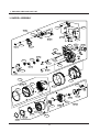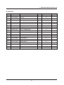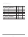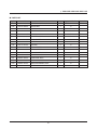
1
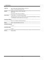
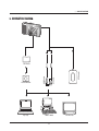
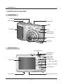
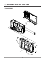
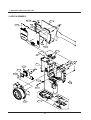
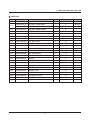
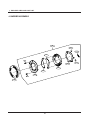
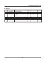
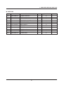
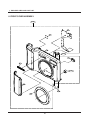
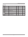
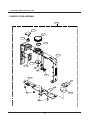
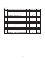
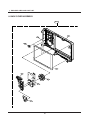
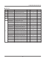
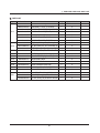
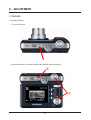
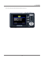
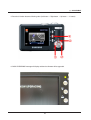
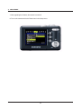
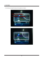
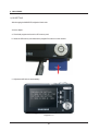
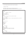
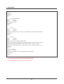
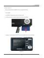
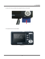
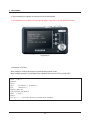
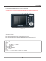
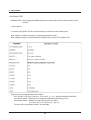
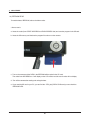
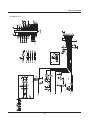
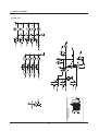
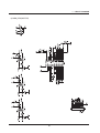
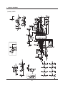
CONTENTS
Ⅰ. SPECIFICATION
1. CAMERA SPECIFICATION ………………………………………………………………………………… 4
2. System Requirements ……………………………………………………………………………………… 7
3. LCD monitor indicator ………………………………………………………………………………………… 8
4. CONNECTION DIAGRAM ………………………………………………………………………………… 11
5. IDENTIFICATION OF FEATURES ………………………………………………………………………… 12
Ⅱ. EXPLODED VIEW AND PARTS LIST
1. MAIN ASSEMBLY…………………………………………………………………………………………… 14
2. BODY ASSEMBLY ………………………………………………………………………………………… 16
3. BARREL ASSEMBLY ……………………………………………………………………………………… 18
4. BARRIER ASSEMBLY ……………………………………………………………………………………… 22
5. STROBO ASSEMBLY ……………………………………………………………………………………… 24
6. FRONT COVER ASSEMBLY ……………………………………………………………………………… 26
7. MIDDLE COVER ASSEMBLY ……………………………………………………………………………… 28
8. BACK COVER ASSEMBLY………………………………………………………………………………… 30
9. PACKING ITEM……………………………………………………………………………………………… 32
Ⅲ. ADJUSTMENT
1. FIRMWARE ………………………………………………………………………………………………… 36
2. ADJUSTMENT CAUTION ………………………………………………………………………………… 53
Ⅳ. PATTERN DIAGRAM
1. PARTS ARRANGEMENT FOR EACH PCB ASS’Y
1) MAIN_TOP
………………………………………………………………………………………………… 88
2) MAIN_BOTTOM
…………………………………………………………………………………………… 89
2
Ⅴ. CIRCUIT DIAGRAM
1) MAIN
……………………………………………………………………………………………………… 90
2) MAIN_DDR
………………………………………………………………………………………………… 91
3) MAIN_CCD(FEP)
4) MAIN_I/O LCD
…………………………………………………………………………………………… 92
……………………………………………………………………………………………… 93
5) MAIN_KEY …………………………………………………………………………………………………… 94
6) MAIN_LENS(MOTOR)
7) MAIN_POWER
……………………………………………………………………………………… 95
……………………………………………………………………………………………… 96
8) MAIN_STROBO ……………………………………………………………………………………………… 97
Ⅵ. SERVICE INFORMATION ………………………………………………………………………………98
3
Ⅰ. SPECIFICATION
1. CAMERA SPECIFICATION
Image Sensor
- Type : 1/1.8" CCD
- Effective Pixel : Approx. 10.1 Mega-pixel
- Total Pixel : Approx. 10.3 Mega-pixel
Lens
- Focal Length : SHD Lens f = 7.4 ~ 22.2mm (35mm film equivalent : 35 ~ 105mm)
- F No. : F2.8 ~ F7.1 (Wide), F5.1 ~ F13.1 (Tele)
- Digital Zoom :·Still Image mode : 1.0X ~ 5.0X
·Play mode : 1.0X ~ 14.3X (depends on image size)
LCD Monitor
- 2.7" color TFT LCD (230,000 dots)
Focusing
- Type : TTL auto focus
- Range :
Wide
Normal
Tele
80cm ~ infinity
Macro
4cm ~ 80cm
50cm ~ 80cm
Auto Macro
4cm ~ Infinity
50cm ~ Infinity
Shutter
- Speed : 1 ~ 1/1,500 sec. (Manual : 8 ~ 1/1,500 sec.)
Exposure
- Control : Program AE
- Metering : Multi, Spot
- Compensation : ±2EV (0.5EV steps)
- ISO Equivalent : Auto, 80,100, 200, 400, 800, 1000
Flash
- Modes : Auto, Auto & Red-eye reduction, Fill-in flash, Slow sync, Flash off
- Range : Wide : 0.4m ~ 4.8m, Tele : 0.5m ~ 4.3m (ISO AUTO)
- Recharging Time : Approx. 5 sec.
Sharpness
- Soft, Normal, Vivid
Effect
- Normal, B&W, Sepia, Red, Blue, Green, Negative, RGB
White Balance
- Auto, Daylight, Cloudy, Fluorescent_H, Fluorescent_L, Tungsten, Custom
Voice Recording
- Voice Recording (max.1 hour)
- Voice Memo in Still Image (max. 10 sec.)
Date Imprinting
- Date, Date&Time, Off (user selectable)
4
Ⅰ. SPECIFICATION
Shooting
- Still Image:
·Modes : Auto, Program, Scene
※ Scene : Night, Portrait, Children (in Mode Dial), Landscape, Close-up, Sunset, Dawn,
Backlight, Fireworks, Beach & Snow
※ Mode Dial : Auto, Program, Manual, Scene, Portrait, Night, Children
·Shooting : Single, Continuous, AEB
·Self-timer : 10 sec., 2 sec., Double (10 sec., 2 sec.)
- Movie Clip :
·With Audio (recording time : memory capacity dependent)
·Size : 640x480, 320x240, 160X128 (3X Optical Zoom, Mute during Zoom Operation)
·Frame rate : 30 fps, 15 fps
·Movie Stabilizer
·Movie Editing (Embedded) : Pause during recording, Still Image Capture, Time Trimming
Storage
- Media :
·Internal memory : Approx.45MB flash memory
·External memory : MMC/ SD card (Up to 2GB Guaranteed)
- File Format :
·Still Image : JPEG (DCF), EXIF 2.2, DPOF 1.1, PictBridge 1.0
·Movie Clip : AVI (MPEG-4)
·Audio : WAV
- Image Size
10M
9M
8M
7M
6M
5M
3648x2736
3472x2604
3264x2448
3072x2304
2816x2112
2592x1944
4M
3M
2M
1M
VGA
-
2272x1704
2048x1536
1600x1200
1024x768
640x480
-
- Capacity (256MB MMC(Multi Media Card))
10M
9M
8M
7M
6M
5M
Super Fine
48
53
60
67
80
93
Fine
94
104
115
128
157
181
Normal
109
151
169
197
223
264
4M
3M
2M
1M
VGA
-
Super Fine
121
148
244
520
1041
-
Fine
226
284
434
868
1116
-
Normal
279
400
520
1041
1302
-
※ These figures are measured under Samsung’s standard conditions and may vary
depending on shooting conditions and camera settings.
5
Ⅰ. SPECIFICATION
Image Play
- Type : Single image, Thumbnails, Slide show, Movie Clip
- Editing : Trimming, Resizing, Rotate, Effect
Interface
- Digital output connector : USB 2.0 High speed
- Audio : Mono
- Video output : NTSC, PAL (user selectable)
Power Source
- Primary Battery : 2 x AA Alkaline (High Capacity)
- Rechargeable battery (Optional) : SNB-2512B KIT (2xAA 2500mAh Ni-MH Battery & Charger)
※ Included battery may vary depending on sales region.
Dimensions (WxHxD)
- 99.6 X 61.8 X 26.95mm (excluding protrusions)
Weight
- Approx. 169g (without batteries and card)
Operating Temperature
- 0 ~ 40°C
Operating Humidity
- 5 ~ 85%
Software
- Digimax Master
6
Ⅰ. SPECIFICATION
2. System Requirements
For Windows
For Macintosh
PC with processor better than Pentium II
Power Mac G3 or later
450MHz (Pentium 700MHz recommended)
Windows 98SE/2000/ME/XP/Vista
Mac OS 9.2 ~ 10.4
Minimum 64MB RAM
200MB of available hard disk space
Minimum 64MB RAM
USB port
USB port
CD-ROM drive
CD-ROM drive
110MB of available hard-disk space
For playing back a movie clip
1024x768 pixels, 16bit color display compatible
Mac OS 10.1 ~ 10.3
monitor 24bit color display recommended)
MPlayer, VLC Media Player
7
Ⅰ. SPECIFICATION
3. LCD monitor indicator
■ Recording mode
①
⑳
②
③
⑲
⑱
④
⑰
⑤
⑯
⑥
⑮
⑦
⑭
⑧
⑬
⑨
⑩ ⑪
[ Image & Full Status ]
8
⑫
Ⅰ. SPECIFICATION
No.
Description
Icons
1
Recording mode
2
Battery
3
Aperture Value / Shutter Speed
4
Continuous shot
5
Flash / Without Sound
6
Self-timer
7
Macro
8
Metering
9
Card inserted indicator
10
Auto focus frame
11
Camera shake warning
12
Date / Time
13
Exposure compensation
14
White Balance
15
ISO
16
RGB
17
Sharpness
18
Image quality / Frame rate
19
Image size
20
Number of available shots remaining
18
Remaining time (Movie clip/ Voice recording)
00:01:30/ 01:00:00
F2.8, 1/30
2007/03/01 01:00 PM
RGB
21
Voice memo
22
Optical/ Digital Zoom bar/ Digital Zoom rate
9
Ⅰ. SPECIFICATION
■ Play mode
⑫
①
②
ISO : 80
Av : F 2.8
Tv : 1/30
Flash : On
3648X2736
2007/03/01
③
④
⑤
No.
Description
Icon
1
Play mode icon
2
Battery
3
Voice Memo
4
Protect
5
DPOF
6
Recording date
2007/03/01
7
Image size
3648x2736 ~ 256x192
8
Flash
On/Off
9
Shutter speed
8 ~ 1/1,500
10
Aperture Value
F2.8 ~ F13.1
11
ISO
80~1000
12
Folder name & File name
100-0007
10
⑪
⑩
⑨
⑧
⑦
⑥
Ⅰ. SPECIFICATION
4. CONNECTION DIAGRAM
Lap top
AC Adaptor
AV Cable
Card Reader
USB Cable
SD Card
IBM / MAC
11
TV Monitor
Ⅰ. SPECIFICATION
5. IDENTIFICATION OF FEATURES
Front & Top
Mode dial
Shutter button
Power button
Speaker
Strap eyelet
Flash
Self-timer lamp /
Auto focus lamp
Lens / Lens cover
Microphone
Back & Bottom
Camera status lamp
Zoom W button
(Thumbnail)
Zoom T button
(Digital zoom)
E (Effects) button
LCD monitor
+ / - button, Delete button
Play mode / Printer button
5 function button
USB / AV connection terminal
Tripod socket
12
Ⅰ. SPECIFICATION
Bottom/ 5-function button
Battery chamber cover
Memory card slot
Battery chamber
Voice memo/ Voice Recording/ Up button
Menu/ OK button
Flash/
Left button
Self-timer/
Right button
Macro/ Down button
Play & Pause button
13
Ⅱ. EXPLODED VIEW AND PART LIST
1. MAIN ASSEMBLY
1-1
1-2
1-1
1-1
14
Ⅱ. EXPLODED VIEW AND PART LIST
▶ PARTS LIST
Fig.No
Parts No.
1-1
SCREW
1-2
SCREW
Parts Name
Q’ty
Supply Available Parts
Q6003042701A
5
X
Q6003048801A
1
X
15
Remarks
Ⅱ. EXPLODED VIEW AND PART LIST
2. BODY ASSEMBLY
2-10
2-14
2-7
2-13
2-6
2-17
2-16
2-9
2-8
2-5
2-12
2-11
2-15
2-1
2-20
2-21
2-19
2-18
2-3
2-4
2-24
2-23
2-22
2-2
2-25
2-26
16
Ⅱ. EXPLODED VIEW AND PART LIST
▶ PARTS LIST
Fig.No
Parts No.
2-1
Q7211083807B
Q’ty
Supply Available Parts
BATTERY CHAMBER
1
O
Q9001125101A
BATTERY COVER ASSY
1
O
SILVER
Q9001125101B
BATTERY COVER ASSY
1
O
BLACK
2-3
Q6107067901A
BATTERY HINGE SPRING
1
O
2-4
Q7011056301A
BATTERY HINGE
1
O
2-5
Q7011055603A
BATTERY CONTACT
2
O
2-6
Q9008120001A
MAIN PCB ASSY-S3-103
1
O
2-7
Q0704014301A
TFT-LCD
1
O
2-10
Q7017052102A
TOP ESD PLATE
1
O
2-11
Q9761175007
TAP TITE SCREW
3
X
2-12
Q7409224601A
TOP FPCB TAPE
1
X
2-13
Q7409256801A
CONN. SHEET
1
X
2-14
Q7409254401A
CRADLE GND. TAPE
1
X
2-15
Q6003018501A
TAP TITE SCREW
2
X
2-16
Q7409254901A
LIGHT TAPE
1
X
2-17
Q0961900301A
SCREW
4
X
2-18
Q2904003702A
IR CUT FILTER
1
O
2-19
Q7304000102A
IR CUT CUSHION
1
O
2-20
Q9505000201A
CCD_FPCB_ASSY
1
O
2-21
Q9765143012
SCREW
3
X
2-22
Q9002145501A
BARREL ASSY
1
O
2-23
Q7217404601A
BATTERY_COVER
1
X
2-24
Q7217368403A
BATTERY EP PLATE
1
X
2-25
Q7011056202A
BATTERY PLATE
1
X
2-26
Q7411131601A
BATTERY CONTACT
1
X
2-2
Parts Name
17
Remarks
Ⅱ. EXPLODED VIEW AND PART LIST
3. BARREL ASSEMBLY
3-50
3-9
3-8
3-51
3-7
3-6
3-5
3-11
3-4
3-49
3-10
3-40
3-2
3-26
3-3
3-1
3-22
3-28
3-27
3-30
3-29
3-23
3-30
3-30
3-17
3-14
3-16
3-24
3-18
3-19
3-25
3-15
3-13
3-20
3-21
3-12
3-54
3-35
3-32
3-46
3-44
3-34
3-31
3-45
3-33
3-43
3-42
3-45
3-41
3-40
3-39
3-47
3-38
3-52
3-37
3-36
18
3-48
3-53
Ⅱ. EXPLODED VIEW AND PART LIST
▶ PARTS LIST
Q’ty
Supply Available Parts
AF CLIP HOLDER
1
O
Q7012088601A
AF CLIP
1
O
3-3
Q9002144601A
3RD LENS ASSY
1
O
3-4
Q6003000201A
SCREW
1
X
3-5
Q6107058303A
3RD BARREL SPRING
1
O
3-6
Q3104000901A
AF MOTOR
1
O
3-7
Q4101034801A
AF FPCB
1
O
3-8
Q4101034701A
MAIN FPCB
1
X
3-9
Q0608001201A
PHOTO INTERRUPTER
1
O
3-10
Q0608001001A
PHOTO INTERRUPTER
1
O
3-11
Q0608000701A
PHOTO REFLECTOR
1
O
3-12
Q0961900301A
SCREW
2
X
3-13
Q7212189502A
ZOOM COVER
1
O
3-14
Q7212189801A
ZOOM GEAR_B
1
O
3-15
Q7212189701A
ZOOMGEAR_A
1
O
3-16
Q7212190001A
ZOOM GEAR_D
1
O
3-17
Q7212189901A
ZOOM GEAR_C
1
O
3-18
Q6001014001A
SCREW
2
X
3-19
Q7012088301A
AF GUIDE HOLDER
1
O
3-20
Q0961900101A
SCREW
1
X
Fig.No
Parts No.
3-1
Q7012080802A
3-2
Parts Name
19
Remarks
Ⅱ. EXPLODED VIEW AND PART LIST
▶ PARTS LIST
Q’ty
Supply Available Parts
SENSOR HOLDER
1
O
Q7411122601A
ZOOM GEAR SHAFT_B
1
O
3-23
Q7411122401A
ZOOM GEAR SHAFT_A
1
O
3-24
Q7411121401A
AF GUIDE BAR_A
1
O
3-25
Q7411121501A
AF GUIDE BAR_B
1
O
3-26
Q7212190902A
LENS BASE
1
O
3-27
Q3107002401A
ZOOM MOTOR
1
O
3-28
Q7212189601A
ZOOM MOTOR GEAR
1
O
3-29
Q9611142007
SCREW
2
X
3-30
Q0961900301A
SCREW
3
X
3-31
Q7012086601A
CAM DECORATION RING
1
O
3-32
Q7212190602A
CAM BARREL
1
O
3-33
Q7212190401A
GUIDE PLATE
1
O
3-34
Q9002145101A
OUTER GUIDE BARREL
1
O
3-35
Q7212190701A
OUTER CAM BARREL
1
O
3-36
Q7409220002A
1ST SHEET
1
O
3-37
Q7012086802A
1ST PUSH PLATE
1
O
Fig.No
Parts No.
3-21
Q7012088401A
3-22
Parts Name
20
Remarks
Ⅱ. EXPLODED VIEW AND PART LIST
▶ PARTS LIST
Q’ty
Supply Available Parts
1ST LENS ASSY
1
O
Q7212190501A
ZOOM RING
1
O
3-40
Q0994913101A
SCREW
1
O
3-41
Q9002144501A1
2ND LENS ASSY
1
O
3-42
Q0961900101A
SCREW
1
O
3-43
Q9005163103A
SHUTTER ASSY
1
O
3-44
Q7012087103A
FPCB GUIDER
1
O
3-45
Q6001014001A
SCREW
2
X
3-46
Q7411120101A
OCB PIN
3
O
3-47
Q7411122201A
1ST MOVE PIN
3
O
3-48
Q7411122302A
2ND MOVE PIN
3
O
3-49
Q9008092201A
AF MOTOR FPCB ASSY
1
O
3-50
Q9008092101A
MAIN FPCB ASSY
1
O
3-51
Q9002145401A
LENS BASE ASSY
1
O
3-52
Q9002144901A
ZOOM RING ASSY
1
O
3-53
Q9002144701A
2ND LENS BARREL ASSY
1
O
3-54
Q9002145301A
OUTER CAM BARREL ASSY
1
O
Fig.No
Parts No.
3-38
Q9002144401A1
3-39
Parts Name
21
Remarks
Ⅱ. EXPLODED VIEW AND PART LIST
4. BARRIER ASSEMBLY
4-9
4-7
4-8
4-4
4-2
4-6
4-5
4-4
4-3
4-2
4-1
22
4-7
Ⅱ. EXPLODED VIEW AND PART LIST
▶ PARTS LIST
Fig.No
Parts No.
4-1
Q7012086503A
4-2
Parts Name
Q’ty
Supply Available Parts
FRONT DECORING
1
O
Q6003048101A
BARRIER SCREW
2
X
4-3
Q7212189103A
FRONT PANE
1
O
4-4
Q7212189302A
BARRIER FRAME
2
O
4-5
Q7212189205A
BARRIER BASE
1
O
4-6
Q7212189404A
BARRIER LEVER
1
O
4-7
Q6107065501A
CLOSE SPRING
2
O
4-8
Q6107065401A
OPEN SPRING
1
O
4-9
Q9002145201A
BARRIER ASSY
1
O
23
Remarks
Ⅱ. EXPLODED VIEW AND PART LIST
5. STROBO ASSEMBLY
5-11
5-10
5-1
5-2
5-4
5-5
5-3
5-6
5-7
5-8
5-9
24
Ⅱ. EXPLODED VIEW AND PART LIST
▶ PARTS LIST
Fig.No
Parts No.
5-1
Q9004088601A
5-2
Parts Name
Q’ty
Supply Available Parts
STROBO PCB ASS'Y
1
X
Q0408001101A
AF LED
1
X
5-3
Q2401007601A
MAIN CONDENSOR
1
X
5-4
Q7211083903A
REFLECTOR HOLDER
1
X
5-5
Q7309048301A
XE TUBE RUBBER
1
X
5-6
Q7011057801A
TRIG CONTACT
1
X
5-7
Q7014004801A
REFLECTOR
1
X
5-8
Q0611003301A
XE TUBE
1
X
5-9
Q7214088801A
FRESNEL LENS
1
X
5-10
Q0961900301A
SCREW
1
X
5-11
Q9004088701A
STROBO ASSY
1
O
25
Remarks
Ⅱ. EXPLODED VIEW AND PART LIST
6. FRONT COVER ASSEMBLY
6-9
6-5
6-6
6-1
6-10
6-7
6-4
6-8
6-2
6-11
6-3
26
Ⅱ. EXPLODED VIEW AND PART LIST
▶ PARTS LIST
Fig.No
Parts No.
6-1
Q7217404401A
6-2
Q’ty
Supply Available Parts
FRONT COVER-S3-103
1
X
Q7217404801A
FRONT HAND GRIP
1
X
6-3
Q7104002701A
FRONT_DECO
1
X
6-4
Q7017052401A
LOGO PLATE
1
X
6-5
Q7017052202A
FRONT PLATE
1
X
6-6
Q7409181102A
EP MASKING TAPE
1
X
6-7
Q7217372502A
AF LED WINDOW
1
X
6-8
Q3003001201A
MIC
1
O
Q9007283301A
FRONT COVER ASSY
1
O
SILVER
Q9007283301B
FRONT COVER ASSY
1
O
BLACK
6-10
Q7211059102A
TRIPOD CONNECTOR
1
O
6-11
Q6003042701A
SCREW
2
X
6-9
Parts Name
27
Remarks
Ⅱ. EXPLODED VIEW AND PART LIST
7. MIDDLE COVER ASSEMBLY
7-17
7-3
7-5
7-2
7-4
7-1
7-16
7-14
7-6
7-7
7-8
7-9
7-12
7-10
7-11
7-13
7-15
28
Ⅱ. EXPLODED VIEW AND PART LIST
▶ PARTS LIST
Fig.No
Parts No.
Parts Name
Q’ty
Supply Available Parts
Remarks
Q7217372807G
MIDDLE COVER KENOX S1030
1
O
SILVER
Q7217372807H
MIDDLE COVER Samsung S1030
1
O
SILVER
7-2
Q6107059701A
RELEASE SPRING
1
O
7-3
Q7217373802A
RELEASE BUTTON
1
O
7-4
Q7017056401A
MODE CLICK PLATE
1
O
7-5
Q7217368802D
MODE DIAL
1
O
7-6
Q9761173007A
SCREW
1
X
7-7
Q7217373602B
DECO LED
1
O
7-8
Q7217369001B
POWER BUTTON
1
O
7-9
Q9007250401A
TOP FPCB PLATE ASS'Y
1
O
7-10
Q7409281102A
EP MASKING TAPE
1
X
7-11
Q3001000601A
SPEAKER
1
O
7-12
Q7409225102A
SPEAKER TAPE
1
X
7-13
Q0961900301A
SCREW
2
X
7-14
Q7217373903A
STRAP INNER HOLDER
1
O
7-15
Q9761173012
SCREW
2
X
7-16
Q9007272001A
MODE CONTACT ASSY
1
O
Q9007283401B
MIDDLE COVER ASSY_KENOX S1030
1
O
SILVER
Q9007283401A
MIDDLE COVER ASSY_Samsung S1030
1
O
SILVER
7-1
7-17
29
Ⅱ. EXPLODED VIEW AND PART LIST
8. BACK COVER ASSEMBLY
8-9
8-1
8-8
8-3
8-2
8-6
8-4
8-5
8-7
30
Ⅱ. EXPLODED VIEW AND PART LIST
▶ PARTS LIST
Fig.No
Parts No.
8-1
Q7117404501A
8-2
Q’ty
Supply Available Parts
BACK COVER
1
X
Q7409280301A
LCD SPONGE
1
X
8-3
Q7217373701A
AF LED LAMP
1
X
8-4
Q7217373402A
NAVI BUTTON
1
X
8-5
Q7017052004A
REAR PLATE
1
X
8-6
Q7217373305B
FUNCTION
1
X
8-7
Q7217373502A
OK BUTTON
1
X
8-8
Q7409255001A
BACK COVER SHEET
1
X
Q9007283101A
BACK COVER ASSY
1
O
SILVER
Q9007283101B
BACK COVER ASSY
1
O
BLACK
8-9
Parts Name
31
Remarks
Ⅱ. EXPLODED VIEW AND PART LIST
9. PACKING ITEM
9-4
9-14
9-13
9-18
9-20
9-21
9-1
9-16
9-17
9-7
9-3
9-6
9-5
9-11
9-10
9-8
9-9
9-19
9-15
9-2
9-12
32
Ⅱ. EXPLODED VIEW AND PART LIST
▶ PARTS LIST
Fig.No
Parts No.
9-1
QP960210101A
9-2
Q’ty
Supply Available Parts
PE BAG (FOR CAMERA)
1
O
Q6909018202A
PE BAG (FOR ACCESSORY)
1
O
9-3
Q6901258701A
MOLD_PULP_Digimax
1
O
9-4
Q7409271401A
STRAP_KENOX_S730_KOR/EXP
1
O
9-5
Q4609018601A
DRIVER_DIGIMAX_MASTER
1
O
9-6
Q6909019801A
AIR BAG_Samsung
1
O
Q6904031201A
POUCH_S3-73_KOR_EXP_BLACK
1
O
Q6904031301A
POUCH_S3-73_KOR_EXP_SILVER
1
O
Q6806398801A
Q_GUIDE_KENOX_S830
1
O
Q6806399101A
Q_GUIDE_Samsung_S830_ENG
1
O
Q6806399201A
Q_GUIDE_Samsung_S830_GER
1
O
Q6806399301A
Q_GUIDE_Samsung_S830_FRA
1
O
Q6806399401A
Q_GUIDE_Samsung_S830_SPA
1
O
Q6806399501A
Q_GUIDE_Samsung_S830_ITA
1
O
Q6806399601A
Q_GUIDE_Samsung_S830_CHI_T
1
O
Q6806399701A
Q_GUIDE_Samsung_S830_DUT
1
O
Q6806399801A
Q_GUIDE_Samsung_S830_POR
1
O
Q6806399901A
Q_GUIDE_Samsung_S830_SWE
1
O
Q6806400001A
Q_GUIDE_Samsung_S830_DEN
1
O
Q6806400101A
Q_GUIDE_Samsung_S830_FIN
1
O
Q6806400201A
Q_GUIDE_Samsung_S830_RUS
1
O
Q6806400301A
Q_GUIDE_Samsung_S830_CHI_S
1
O
Q6806400401A
Q_GUIDE_Samsung_S830_TK
1
O
Q6806400501A
Q_GUIDE_Samsung_S830_IND
1
O
Q6806400601A
Q_GUIDE_Samsung_S830_ARA
1
O
Q6806400701A
Q_GUIDE_Samsung_S830_THA
1
O
9-7
9-8
Parts Name
33
Remarks
Ⅱ. EXPLODED VIEW AND PART LIST
▶ PARTS LIST
Fig.No
9-9
9-10
Parts No.
Parts Name
Q’ty
Supply Available Parts
Q6806398901A
U_MANUAL_KENOX S830
1
O
Q6806400801A
U_MANUAL_Samsung_S830_ENG
1
O
Q6806400901A
U_MANUAL_Samsung_S830_GER
1
O
Q6806401001A
U_MANUAL_Samsung_S830_FRA
1
O
Q6806401101A
U_MANUAL_Samsung_S830_SPA
1
O
Q6806401201A
U_MANUAL_Samsung_S830_ITA
1
O
Q6806401301A
U_MANUAL_Samsung_S830_CHI_T
1
O
Q6806401401A
U_MANUAL_Samsung_S830_DUT
1
O
Q6806401501A
U_MANUAL_Samsung_S830_POR
1
O
Q6806401601A
U_MANUAL_Samsung_S830_SWE
1
O
Q6806401701A
U_MANUAL_Samsung_S830_DEN
1
O
Q6806401801A
U_MANUAL_Samsung_S830_FIN
1
O
Q6806401901A
U_MANUAL_Samsung_S830_RUS
1
O
Q6806402001A
U_MANUAL_Samsung_S830_CHI_S
1
O
Q6806402101A
U_MANUAL_Samsung_S830_TK
1
O
Q6806402201A
U_MANUAL_Samsung_S830_IND
1
O
Q6806402301A
U_MANUAL_Samsung_S830_ARA
1
O
Q6806402401A
U_MANUAL_Samsung_S830_THA
1
O
Q6806399001A
QS_MANUAL_KENOX S830
1
O
Q6806402501A
QS_MAN_S830_E_G_F_SP_I_DU_P_7
1
O
Q6806402601A
QS_MAN_S830_E_G_FI_SW_DA_RU_6
1
O
Q6806402701A
QS_MAN_S830_E_TU_CH_IN_AR_TH_6
1
O
Q6806402801A
QS_MAN_S830_EN_SP_FR_3
1
O
34
Remarks
Ⅱ. EXPLODED VIEW AND PART LIST
▶ PARTS LIST
Fig.No
Parts No.
Parts Name
Q’ty
Supply Available Parts
QP955150101F
WARRANTY CARD_KOREA
1
O
Q6807012301A
WARRANTY CARD_2 YERARS
1
O
Q6807010903C
WARRANTY CARD_RUS(3 YEARS)
1
O
Q6807011301B
WARRANTY CARD_TSOE(CHINA)
1
O
Q6807009502E
CARD_PRODUCT(Mexico)
1
O
Q6807012101A
WARRANTY CARD_IRAN
1
O
Q6807012401A
WARRANTY CARD_TURKEY
1
O
Q6901268701A
GT_BOX_KENOX_S830_SBC-N2_Silver
1
O
Q6901268801A
GT_BOX_S830_EXP_AUS_ALKALINE_SL
1
O
Q6901268901A
GT_BOX_S830_USA_CAN_ALKALINE_SL
1
O
9-13
Q4301001801A
ALKALINE (1.5V, AA) 2EA - DURACEL ULTRA
1
O
9-14
Q4302000901A
BATTERY_SNB-2512(AA Type)
1
O
9-15
Q6804096001A
COLOR STICKER_Digimax S500_BLACK
1
O
9-16
3802005001A
18PIN-USB CABLE
1
O
9-17
3802005101A
18PIN-AV CABLE
1
O
9-18
Q4309002301A
Ni-MH CHARGER(SBC-N2)
1
O
9-19
Q6806368001A
MANUAL_SNB-2512B KIT_KOR
1
O
9-20
Q3801003001A
AC CODE CABLE_KOR-D1
1
O
Q7409284901A
MIC LABEL_KENOX S830(MADE IN CHINA)
1
O
Q7409285001A
FCC LABEL_Samsung_S830_EXP (MADE IN CHINA)
1
O
Q7409272601A
FCC LABEL_Samsung_S830_EXP (MADE BY SAMSUNG)
1
O
9-11
9-12
9-21
35
Remarks
Ⅲ. ADJUSTMENT
1. FIRMWARE
1) Reseting Camera
1. Turn on the Camera
2. Press and hold the Up button and Shutter button and then press the Power off
36
Ⅲ. ADJUSTMENT
3. Turn on the camera and check whether the camera is reset or not.
37
Ⅲ. ADJUSTMENT
2) Checking version
1. Remove the memory card from the camera.
2. Turn on the camera
38
Ⅲ. ADJUSTMENT
3. Press the Up button twice to select the Voice Recording mode.
4. Press the 5 function button as following order. (Left button → Right button → Up button → +/- button)
39
Ⅲ. ADJUSTMENT
5. Check the Firmware and turn off the camera.
40
Ⅲ. ADJUSTMENT
3) UPGRADING
1. Insert the SD card that has the firmware.
* Updating the firmware will delete all data in the SD card. Be sure to download all data to your PC before
updating the firmware.
The firmware file name must be " STS3_103.elf " and use the AC adapter or fully charged battery.
2. Use the AC adapter or fully charged battery.
To upgrade the Firmware, all of the battery level indicator on the LCD monitor must be displayed.
41
Ⅲ. ADJUSTMENT
3. Turn on the camera
4. Press the Up button twice to select the Voice Recording mode.
42
Ⅲ. ADJUSTMENT
5. Press the 5 function button as following order. (Left button → Right button → Up button → +/- button)
6. 'NOW UPGRADING!' message will display and then the firmware will be upgraded.
43
Ⅲ. ADJUSTMENT
7. After upgrading the firmware, the camera is turned off.
8. Turn on the camera and do the 'Reset' menu in the Setup menu.
44
Ⅲ. ADJUSTMENT
4) Full Version of Firmware
How to use the FULL version of Firmware1
When the camera is not turned on, do the Full version upgrade.
▷Camera Status : When turning on the camera, the power consumption (Checking the POWER SUPPLY) is
200-300mA and the camera cant be operated.
▷Cause
: The data of 0 address in the FLASH MEMORY of the MAIN PCB is damaged.
▷Solution
: Recover the address by doing the FULL VERSION FIRMWARE shown below.
▷Additions
: After completing the upgrading of the FULL VERSION FIRMWARE, do the LENS
SHADINGand ÄCCD DEFECT CELL adjustment.
1.Short the 3 point of the MAIN PCB as shown.
45
Ⅲ. ADJUSTMENT
2. Assemble the camera correctly and insert the SD card that has the Full version of firmware.
* The firmware file name must be " STS3_103_full.elf "
3. Turn on the camera by using the Power Supply.
To connect the camera and Power Supply, use the Battery Tool.
4. If the Current is up to 200mA and down to 0 on the POWER SUPPLY display, the upgrade is complete.
46
Ⅲ. ADJUSTMENT
How to use the FULL firmware 2
Depending on the camera status, do the full version upgrade.
Reference :
▷R
- Delete all data in the memory card and upgrade with this firmware.
- When using the full version upgrade, back up the script file as the files will be deleted by the upgrade.
- If the full version upgrade is done by the following way, the script files are saved on the SD card.
To upload the script files, do not remove the SD card and refer to instructions listed below.
- If there are LSCLUT0.BIN, DefectivePixel0.bin, DefectivePixel1.bin files on the SD card, the back up was
complete.
1. Insert the SD card that has the Full version of firmware.
* Updating the firmware will delete all data in the SD card. Be sure to download all data to your PC before
updating the firmware.
The firmware file name must be " STS3_103.elf " and use the AC adapter or fully charged battery.
47
Ⅲ. ADJUSTMENT
2. Use the AC adaptor or fully charged battery.
To upgrade the Firmware, all of the battery level indicator on the LCD monitor must be displayed.
3. Turn on the Camera.
48
Ⅲ. ADJUSTMENT
4. Press the Up button twice to select the Voice Recording mode.
5. Press the 5 function button as following order. (Left button → Right button → Down button → +/- button)
49
Ⅲ. ADJUSTMENT
6. 'NOW UPGRADING!' message will display and then the firmware will be upgraded.
- After completing the upgrading, back up files will be made on the SD memory card.
Backup file names are LSCLUT0.BIN, DefectivePixel0.bin and DefectivePixel1.bin .
50
Ⅲ. ADJUSTMENT
7. After upgrading the Full version firmware, upload the script files.
Turn on the camera and press the Up button twice to select the Voice Recording mode.
Press the 5 function button as following order :Tele button → Wide button → Down button → OK button.
51
Ⅲ. ADJUSTMENT
8. The following message will display and the upgrading is complete.
52
Ⅲ. ADJUSTMENT
2. ADJUSTMENT CAUTION
1) Basic Information of Adjustment
After changing the electronic parts of S1030, the parts have to be adjusted in accordance withe the adjusted items.
The items listed on the table are have to be adjusted after changing.
1> To adjust the camera after changing the electronic parts, see the below table.
FIRMWARE UPGRADE
PUNT ADJ.
SHUTTER CLOSE TIME ADJ.
BACK LASH ADJ.
FLASH ADJ.
BATTERY LEVEL ADJ.
OB SETTING
BURNING TEST & CCD DEFECT CELL
EEPROM READ
EEPROM WRITE
MAIN
PCB
●
●
●
●
●
●
●
●
2> Equipment
▶ Equipments
- AE TESTER : AE TESET can test up to LV 16.7.
- POWER SUPPLY : 3.3V / 2A
▶ Chart
- Focus Chart
- Gray Chart(36%..Reflection Paper)
53
POWER
PCB
BARREL
ASS’Y
●
●
●
●
CCD
ASS’Y
●
●
●
●
●
●
●
●
●
Ⅲ. ADJUSTMENT
3> Adjustment program file
To adjust all items, all kinds of code by items have to be inserted in program file and saved them to the SD card
as TXT file type. The codes are listed below.
< Description of TXT file >
Use the Memo pad of Basic Windows program and save it as "STS3_103ADJ.TXT".
<1>18; /* OB */
<2>65535;
<3>18,1;
<4>1,1; E2P WRITE(1), SD WRITE(1)
<5>0; REPEAT(0=1)
<6>8,0,0,0,3000,1500;
<7>30,0,0,0,3000,1500,65535,0;
<8>23; /* 8 ADJ */
<9>23,2;
<10>1,0,1,1,1,1,1,1;LS,DF,BATT,BLASH,SC,STROBO,PUNT,CURRENT
; /* LENS SHADING */
<11>1,1; E2P,SD
<12>1,3,100,0; REPEAT,NG REPEAT,LUT LOADING PERCENTAGE,BEFORE CAP SKIP(0:SKIP)
<13>65,120; MIN,MAX
<14>65535;
<15>0;
; /* DEFECT PIXEL */
<16>1,1;
<17>0;
<18>1,3000,400,6;
<19>20000,0;
<20>65535;
<21>0;
; /* BATT LEVEL */
<22>1,1; E2P,SD
<23>0; REPEAT
<24>96,104; MIN,MAX
<25>92,88,85,83,88;HALF1,LOW1,EMPTY1,LOCK1,START1
<26>93,90,87,82,85;HALF2,LOW2,EMPTY2,LOCK2,START2
<27>65535;
<28>0;
54
Ⅲ. ADJUSTMENT
; /* BACKLASH */
<29>1,1; E2P,SD
<30>1,2; REPEAT,REPEAT FOR AVG
<31>50;
<32>65535;
<33>0;
; /* SHUTTER CLOSING */
<34>1,1; E2P,SD
<35>1; REPEAT
<36>1,480,450,19,2,15;
<37>65535;
<38>0;
; /* FLASH */
<39>1,1; E2P,SD
<40>1; REPEAT
<41>960,550,750,500,1150,155,360,310,710,,680,543,360,300,9;MAX,MIN,MID,AWB
<42>65535;
<43>0;
; /* PUNT */
<44>1,1; E2P,SD
<45>0; REPEAT
<46>0,0,1,2,3,4,5,6,7;IRIS(대),ZOOM STEP
<47>20,394,21,429,32,418,46,404,61,397,79,395,100,402,122,412;Searching Range
<48>34,373,41,408,52,398,66,384,81,376,99,375,120,381,142,391;Limitation
<49>-43,10,-39,10,-38,20,-21,11,-14,20,-10,25,-10,38; Change Available limit
<50>65535;
<51>0;
; /* CURRENT */
<52>0,0; E2P,SD
<53>1,6,18,52,4,3,42,12;REPEAT,COMMAND CNT,COMMAND
<54>0,65534;
<55>0;
※SD CARD SHOULD BE FORMATTED BEFORE USING.
※ fter inserting each code, [;] mark has to be inserted.
55
Ⅲ. ADJUSTMENT
2) OB SETTING
After changing the MAIN PCB, adjust the black color.
<How to adjust>
a...Download program and save it to SD memory card.
b...Insert the SD memory card that has the program file and turn on the camera.
c...Adjustment will be done automatically.
<Figure 1-1>
56
Ⅲ. ADJUSTMENT
d...After completing the adjustment, the camera is turned off automatically.
< Description of TXT file >
When making or modifying the program, see the following program codes.
When modify the program, use the Memo Pad of Windows and save it as "STS3_103ADJ.TXT".
<1>18; /* OB */
<2>65535;
<3>18,1;
<4>1,1; E2P WRITE(1), SD WRITE(1)
<5>0; REPEAT(0=1)
<6>8,0,0,0,3000,1500;
<7>30,0,0,0,3000,1500,65535,0;
<8>23; /* 8 ADJ */
<9>23,2;
<10>1,0,1,1,1,1,1,1;LS,DF,BATT,BLASH,SC,STROBO,PUNT,CURRENT
; /* LENS SHADING */
<11>1,1; E2P,SD
<12>1,3,100,0; REPEAT,NG REPEAT,LUT LOADING PERCENTAGE,BEFORE CAP SKIP(0:SKIP)
<13>65,120; MIN,MAX
<14>65535;
<15>0;
; /* DEFECT PIXEL */
<16>1,1;
<17>0;
<18>1,3000,400,6;
<19>20000,0;
<20>65535;
<21>0;
; /* BATT LEVEL */
<22>1,1; E2P,SD
<23>0; REPEAT
<24>96,104; MIN,MAX
<25>92,88,85,83,88;HALF1,LOW1,EMPTY1,LOCK1,START1
<26>93,90,87,82,85;HALF2,LOW2,EMPTY2,LOCK2,START2
<27>65535;
<28>0;
; /* BACKLASH */
<29>1,1; E2P,SD
<30>1,2; REPEAT,REPEAT FOR AVG
57
Ⅲ. ADJUSTMENT
<31>50;
<32>65535;
<33>0;
; /* SHUTTER CLOSING */
<34>1,1; E2P,SD
<35>1; REPEAT
<36>1,480,450,19,2,15;
<37>65535;
<38>0;
; /* FLASH */
<39>1,1; E2P,SD
<40>1; REPEAT
<41>960,550,750,500,1150,155,360,310,710,,680,543,360,300,9;MAX,MIN,MID,AWB
<42>65535;
<43>0;
; /* PUNT */
<44>1,1; E2P,SD
<45>0; REPEAT
<46>0,0,1,2,3,4,5,6,7;IRIS(대),ZOOM STEP
<47>20,394,21,429,32,418,46,404,61,397,79,395,100,402,122,412;Searching Range
<48>34,373,41,408,52,398,66,384,81,376,99,375,120,381,142,391;Limitation
<49>-43,10,-39,10,-38,20,-21,11,-14,20,-10,25,-10,38; Change Available limit
<50>65535;
<51>0;
; /* CURRENT */
<52>0,0; E2P,SD
<53>1,6,18,52,4,3,42,12;REPEAT,COMMAND CNT,COMMAND
<54>0,65534;
<55>0;
※SD CARD SHOULD BE FORMATTED BEFORE USING.
※ fter inserting each code, [;] mark has to be inserted.
58
Ⅲ. ADJUSTMENT
3) LENS SHADING
This menu adjust the brightness gaps between center of the lens and around the lens.
Required Equipment : AE TESTER(LV: 8.2)
< How to adjust >
a...Prepare AE TESTER can be test up to LV16.1.
b...Download program file and save it to SD memory card.
c...Insert the SD memory card that has the program file and attach the camera to the AE TESTER.
d...Attach the camera on the AE METER and set the LV as 8.2.
59
Ⅲ. ADJUSTMENT
e...Turn on the camera.
f...Process will be displayed on the TFT LCD and the adjustment will be done automatically.
<Figure 2-1>
e...After completing the upgrade, the camera is turned off automatically.
※ If the adjustment is incomplete, NG message will display. In this case, re-try the adjustment process.
<Figure 2-2>
60
Ⅲ. ADJUSTMENT
< Description of TXT file >
When making or modifying the program, see the following program codes.
When modify the program, use the Memo Pad of Windows and save it as"STS3_103ADJ.TXT"
<1>18; /* OB */
<2>65535;
<3>18,1;
<4>1,1; E2P WRITE(1), SD WRITE(1)
<5>0; REPEAT(0=1)
<6>8,0,0,0,3000,1500;
<7>30,0,0,0,3000,1500,65535,0;
<8>23; /* 8 ADJ */
<9>23,2;
<10>1,0,1,1,1,1,1,1;LS,DF,BATT,BLASH,SC,STROBO,PUNT,CURRENT
; /* LENS SHADING */
<11>1,1; E2P,SD
<12>1,3,100,0; REPEAT,NG REPEAT,LUT LOADING PERCENTAGE,BEFORE CAP SKIP(0:SKIP)
<13>65,120; MIN,MAX
<14>65535;
<15>0;
; /* DEFECT PIXEL */
<16>1,1;
<17>0;
<18>1,3000,400,6;
<19>20000,0;
<20>65535;
<21>0;
; /* BATT LEVEL */
<22>1,1; E2P,SD
<23>0; REPEAT
<24>96,104; MIN,MAX
<25>92,88,85,83,88;HALF1,LOW1,EMPTY1,LOCK1,START1
<26>93,90,87,82,85;HALF2,LOW2,EMPTY2,LOCK2,START2
<27>65535;
<28>0;
; /* BACKLASH */
<29>1,1; E2P,SD
<30>1,2; REPEAT,REPEAT FOR AVG
<31>50;
<32>65535;
<33>0;
61
Ⅲ. ADJUSTMENT
; /* SHUTTER CLOSING */
<34>1,1; E2P,SD
<35>1; REPEAT
<36>1,480,450,19,2,15;
<37>65535;
<38>0;
; /* FLASH */
<39>1,1; E2P,SD
<40>1; REPEAT
<41>960,550,750,500,1150,155,360,310,710,,680,543,360,300,9;MAX,MIN,MID,AWB
<42>65535;
<43>0;
; /* PUNT */
<44>1,1; E2P,SD
<45>0; REPEAT
<46>0,0,1,2,3,4,5,6,7;IRIS(대),ZOOM STEP
<47>20,394,21,429,32,418,46,404,61,397,79,395,100,402,122,412;Searching Range
<48>34,373,41,408,52,398,66,384,81,376,99,375,120,381,142,391;Limitation
<49>-43,10,-39,10,-38,20,-21,11,-14,20,-10,25,-10,38; Change Available limit
<50>65535;
<51>0;
; /* CURRENT */
<52>0,0; E2P,SD
<53>1,6,18,52,4,3,42,12;REPEAT,COMMAND CNT,COMMAND
<54>0,65534;
<55>0;
※SD CARD SHOULD BE FORMATTED BEFORE USING.
※ fter inserting each code, [;] mark has to be inserted.
62
Ⅲ. ADJUSTMENT
4) BACK LASH ADJ
After changing the MAIN PCB, BARREL and CCD, adjust the BACK LASH.
< How to adjust >
a...Download the Program file and save it to SD memory card.
b...Insert the SD memory card that has program file and turn on the camera.
c...<Figure 3-1> will be displayed on the TFT LCD and the adjustment will be done automatically.
<Figure 3-1>
63
Ⅲ. ADJUSTMENT
d...After completing the upgrade, the camera is turned off automatically.
< Description of TXT file >
When making or modifying the program, see the following program codes.
When modify the program, use the Memo Pad of Windows and save it as "STS3_103ADJ.TXT".
<1>18; /* OB */
<2>65535;
<3>18,1;
<4>1,1; E2P WRITE(1), SD WRITE(1)
<5>0; REPEAT(0=1)
<6>8,0,0,0,3000,1500;
<7>30,0,0,0,3000,1500,65535,0;
<8>23; /* 8 ADJ */
<9>23,2;
<10>1,0,1,1,1,1,1,1;LS,DF,BATT,BLASH,SC,STROBO,PUNT,CURRENT
; /* LENS SHADING */
<11>1,1; E2P,SD
<12>1,3,100,0; REPEAT,NG REPEAT,LUT LOADING PERCENTAGE,BEFORE CAP SKIP(0:SKIP)
<13>65,120; MIN,MAX
<14>65535;
<15>0;
; /* DEFECT PIXEL */
<16>1,1;
<17>0;
<18>1,3000,400,6;
<19>20000,0;
<20>65535;
<21>0;
; /* BATT LEVEL */
<22>1,1; E2P,SD
<23>0; REPEAT
<24>96,104; MIN,MAX
<25>92,88,85,83,88;HALF1,LOW1,EMPTY1,LOCK1,START1
<26>93,90,87,82,85;HALF2,LOW2,EMPTY2,LOCK2,START2
<27>65535;
<28>0;
64
Ⅲ. ADJUSTMENT
; /* BACKLASH */
<29>1,1; E2P,SD
<30>1,2; REPEAT,REPEAT FOR AVG
<31>50;
<32>65535;
<33>0;
; /* SHUTTER CLOSING */
<34>1,1; E2P,SD
<35>1; REPEAT
<36>1,480,450,19,2,15;
<37>65535;
<38>0;
; /* FLASH */
<39>1,1; E2P,SD
<40>1; REPEAT
<41>960,550,750,500,1150,155,360,310,710,,680,543,360,300,9;MAX,MIN,MID,AWB
<42>65535;
<43>0;
; /* PUNT */
<44>1,1; E2P,SD
<45>0; REPEAT
<46>0,0,1,2,3,4,5,6,7;IRIS(대),ZOOM STEP
<47>20,394,21,429,32,418,46,404,61,397,79,395,100,402,122,412;Searching Range
<48>34,373,41,408,52,398,66,384,81,376,99,375,120,381,142,391;Limitation
<49>-43,10,-39,10,-38,20,-21,11,-14,20,-10,25,-10,38; Change Available limit
<50>65535;
<51>0;
; /* CURRENT */
<52>0,0; E2P,SD
<53>1,6,18,52,4,3,42,12;REPEAT,COMMAND CNT,COMMAND
<54>0,65534;
<55>0;
※SD CARD SHOULD BE FORMATTED BEFORE USING.
※ fter inserting each code, [;] mark has to be inserted.
65
Ⅲ. ADJUSTMENT
5) B/T LEVEL ADJ
After changing the MAIN PCB, adjust WARNING LEVEL and LOCK LEVEL.
Required Equipment : POWER SUPPLY(2.71V)
< How to adjust >
a...Prepare the POWER..SUPPLY.
b...Connect the camera to the POWER..SUPPLY.
c...Set the voltage to 2.71V.
d...Downloading the program file and save it to SD memory card.
66
Ⅲ. ADJUSTMENT
e...Insert the SD memory card and turn on the camera.
f...The adjustment will be done automatically. There are no displays on the LCD.
g...After completing the upgrade, the camera is turned off automatically.
< Description of TXT file >
When making or modifying the program, see the following program codes.
When modify the program, use the Memo Pad of Windows and save it as "STS3_103ADJ.TXT".
<1>18; /* OB */
<2>65535;
<3>18,1;
<4>1,1; E2P WRITE(1), SD WRITE(1)
<5>0; REPEAT(0=1)
<6>8,0,0,0,3000,1500;
<7>30,0,0,0,3000,1500,65535,0;
<8>23; /* 8 ADJ */
<9>23,2;
<10>1,0,1,1,1,1,1,1;LS,DF,BATT,BLASH,SC,STROBO,PUNT,CURRENT
67
Ⅲ. ADJUSTMENT
; /* LENS SHADING */
<11>1,1; E2P,SD
<12>1,3,100,0; REPEAT,NG REPEAT,LUT LOADING PERCENTAGE,BEFORE CAP SKIP(0:SKIP)
<13>65,120; MIN,MAX
<14>65535;
<15>0;
; /* DEFECT PIXEL */
<16>1,1;
<17>0;
<18>1,3000,400,6;
<19>20000,0;
<20>65535;
<21>0;
; /* BATT LEVEL */
<22>1,1; E2P,SD
<23>0; REPEAT
<24>96,104; MIN,MAX
<25>92,88,85,83,88;HALF1,LOW1,EMPTY1,LOCK1,START1
<26>93,90,87,82,85;HALF2,LOW2,EMPTY2,LOCK2,START2
<27>65535;
<28>0;
; /* BACKLASH */
<29>1,1; E2P,SD
<30>1,2; REPEAT,REPEAT FOR AVG
<31>50;
<32>65535;
<33>0;
; /* SHUTTER CLOSING */
<34>1,1; E2P,SD
<35>1; REPEAT
<36>1,480,450,19,2,15;
<37>65535;
<38>0;
; /* FLASH */
<39>1,1; E2P,SD
<40>1; REPEAT
<41>960,550,750,500,1150,155,360,310,710,,680,543,360,300,9;MAX,MIN,MID,AWB
<42>65535;
<43>0;
68
Ⅲ. ADJUSTMENT
; /* PUNT */
<44>1,1; E2P,SD
<45>0; REPEAT
<46>0,0,1,2,3,4,5,6,7;IRIS(대),ZOOM STEP
<47>20,394,21,429,32,418,46,404,61,397,79,395,100,402,122,412;Searching Range
<48>34,373,41,408,52,398,66,384,81,376,99,375,120,381,142,391;Limitation
<49>-43,10,-39,10,-38,20,-21,11,-14,20,-10,25,-10,38; Change Available limit
<50>65535;
<51>0;
; /* CURRENT */
<52>0,0; E2P,SD
<53>1,6,18,52,4,3,42,12;REPEAT,COMMAND CNT,COMMAND
<54>0,65534;
<55>0;
※SD CARD SHOULD BE FORMATTED BEFORE USING.
※ fter inserting each code, [;] mark has to be inserted.
69
Ⅲ. ADJUSTMENT
6) SHUTTER CLOSE TIME ADJ
After changing the MAIN PCB, BARREL and CCD, adjust the SHUTTER CLOSE TIME.
Required Equipment: AE TESTER(LV 15.8)
< How to adjust >
a...Prepare AE TESTER that can be test up to LV 16.0
0.1.
b...Attach the camera to the AE TESTER.
c...Set the LV to 15.8
0.1.
d...Download the program and save it to SD memory card.
e...Insert the SD memory card that has the program file and turn on the camera.
70
Ⅲ. ADJUSTMENT
f...The adjustment will be done automatically.
<Figure 5-1>
g...After completing the upgrade, the camera is turned off automatically.
※ If the adjustment is incomplete, <Figure 5-2> will display. In this case, re-try the adjustment process.
<Figure 5-1>
71
Ⅲ. ADJUSTMENT
< Description of TXT file >
When making or modifying the program, see the following program codes.
When modify the program, use the Memo Pad of Windows and save it as "STS3_103ADJ.TXT".
<1>18; /* OB */
<2>65535;
<3>18,1;
<4>1,1; E2P WRITE(1), SD WRITE(1)
<5>0; REPEAT(0=1)
<6>8,0,0,0,3000,1500;
<7>30,0,0,0,3000,1500,65535,0;
<8>23; /* 8 ADJ */
<9>23,2;
<10>1,0,1,1,1,1,1,1;LS,DF,BATT,BLASH,SC,STROBO,PUNT,CURRENT
; /* LENS SHADING */
<11>1,1; E2P,SD
<12>1,3,100,0; REPEAT,NG REPEAT,LUT LOADING PERCENTAGE,BEFORE CAP SKIP(0:SKIP)
<13>65,120; MIN,MAX
<14>65535;
<15>0;
; /* DEFECT PIXEL */
<16>1,1;
<17>0;
<18>1,3000,400,6;
<19>20000,0;
<20>65535;
<21>0;
; /* BATT LEVEL */
<22>1,1; E2P,SD
<23>0; REPEAT
<24>96,104; MIN,MAX
<25>92,88,85,83,88;HALF1,LOW1,EMPTY1,LOCK1,START1
<26>93,90,87,82,85;HALF2,LOW2,EMPTY2,LOCK2,START2
<27>65535;
<28>0;
; /* BACKLASH */
<29>1,1; E2P,SD
<30>1,2; REPEAT,REPEAT FOR AVG
<31>50;
<32>65535;
<33>0;
72
Ⅲ. ADJUSTMENT
; /* SHUTTER CLOSING */
<34>1,1; E2P,SD
<35>1; REPEAT
<36>1,480,450,19,2,15;
<37>65535;
<38>0;
; /* FLASH */
<39>1,1; E2P,SD
<40>1; REPEAT
<41>960,550,750,500,1150,155,360,310,710,,680,543,360,300,9;MAX,MIN,MID,AWB
<42>65535;
<43>0;
; /* PUNT */
<44>1,1; E2P,SD
<45>0; REPEAT
<46>0,0,1,2,3,4,5,6,7;IRIS(대),ZOOM STEP
<47>20,394,21,429,32,418,46,404,61,397,79,395,100,402,122,412;Searching Range
<48>34,373,41,408,52,398,66,384,81,376,99,375,120,381,142,391;Limitation
<49>-43,10,-39,10,-38,20,-21,11,-14,20,-10,25,-10,38; Change Available limit
<50>65535;
<51>0;
; /* CURRENT */
<52>0,0; E2P,SD
<53>1,6,18,52,4,3,42,12;REPEAT,COMMAND CNT,COMMAND
<54>0,65534;
<55>0;
※SD CARD SHOULD BE FORMATTED BEFORE USING.
※ fter inserting each code, [;] mark has to be inserted.
73
Ⅲ. ADJUSTMENT
7) FLASH ADJ
After changing the MAIN PCB and SUB PCB, adjust the FLASH.
Required Equipment : Dark room, Gray chart (36% reflect paper), Tripod
< How to adjust >
a...Arrange a 36% reflect chart in a darkroom..
b... Arrange a camera in a darkroom. (Use TRIPOD)
c...The distance between the reflect chart and the camera should be 80cm.
d...Download the program and save it to SD memory card.
74
Ⅲ. ADJUSTMENT
e...Insert the SD memory card that has the program file and turn on the camera.
f...The adjustment will be done automatically.
<Figure 6-1>
75
Ⅲ. ADJUSTMENT
g...After completing the upgrade, the camera is turned off automatically.
※ If the adjustment is incomplete, NG message will display. In this case, re-try the adjustment process.
<Figure 6-2>
< Description of TXT file >
When making or modifying the program, see the following program codes.
When modify the program, use the Memo Pad of Windows and save it as "STS3_103ADJ.TXT".
<1>18; /* OB */
<2>65535;
<3>18,1;
<4>1,1; E2P WRITE(1), SD WRITE(1)
<5>0; REPEAT(0=1)
<6>8,0,0,0,3000,1500;
<7>30,0,0,0,3000,1500,65535,0;
<8>23; /* 8 ADJ */
<9>23,2;
<10>1,0,1,1,1,1,1,1;LS,DF,BATT,BLASH,SC,STROBO,PUNT,CURRENT
76
Ⅲ. ADJUSTMENT
; /* LENS SHADING */
<11>1,1; E2P,SD
<12>1,3,100,0; REPEAT,NG REPEAT,LUT LOADING PERCENTAGE,BEFORE CAP SKIP(0:SKIP)
<13>65,120; MIN,MAX
<14>65535;
<15>0;
; /* DEFECT PIXEL */
<16>1,1;
<17>0;
<18>1,3000,400,6;
<19>20000,0;
<20>65535;
<21>0;
; /* BATT LEVEL */
<22>1,1; E2P,SD
<23>0; REPEAT
<24>96,104; MIN,MAX
<25>92,88,85,83,88;HALF1,LOW1,EMPTY1,LOCK1,START1
<26>93,90,87,82,85;HALF2,LOW2,EMPTY2,LOCK2,START2
<27>65535;
<28>0;
; /* BACKLASH */
<29>1,1; E2P,SD
<30>1,2; REPEAT,REPEAT FOR AVG
<31>50;
<32>65535;
<33>0;
; /* SHUTTER CLOSING */
<34>1,1; E2P,SD
<35>1; REPEAT
<36>1,480,450,19,2,15;
<37>65535;
<38>0;
; /* FLASH */
<39>1,1; E2P,SD
<40>1; REPEAT
<41>960,550,750,500,1150,155,360,310,710,,680,543,360,300,9;MAX,MIN,MID,AWB
<42>65535;
<43>0;
77
Ⅲ. ADJUSTMENT
; /* PUNT */
<44>1,1; E2P,SD
<45>0; REPEAT
<46>0,0,1,2,3,4,5,6,7;IRIS(대),ZOOM STEP
<47>20,394,21,429,32,418,46,404,61,397,79,395,100,402,122,412;Searching Range
<48>34,373,41,408,52,398,66,384,81,376,99,375,120,381,142,391;Limitation
<49>-43,10,-39,10,-38,20,-21,11,-14,20,-10,25,-10,38; Change Available limit
<50>65535;
<51>0;
; /* CURRENT */
<52>0,0; E2P,SD
<53>1,6,18,52,4,3,42,12;REPEAT,COMMAND CNT,COMMAND
<54>0,65534;
<55>0;
※SD CARD SHOULD BE FORMATTED BEFORE USING.
※ fter inserting each code, [;] mark has to be inserted.
78
Ⅲ. ADJUSTMENT
8) FOCUS ADJ
After changing the MAIN PCB and BARREL, adjust the PUNT.
Required Equipment : Chart for FOCUS adjustment,Tripod
< How to adjust >
a... Arrange a chart for adjust the FOCUS.
b... Attach the camera to the tripod.
c...The distance between the chart and the camera should be 80cm.
AF Chart
d...Download the program and save it to SD memory card.
79
Ⅲ. ADJUSTMENT
e...Insert the SD memory card that has the program file and turn on the camera.
f...The adjustment will be done automatically.
<Figure 7-1>
80
Ⅲ. ADJUSTMENT
g...After completing the upgrade, the camera is turned off automatically.
※ If the adjustment is incomplete, NG message will display. In this case, re-try the adjustment process.
<Figure 7-2>
< Description of TXT file >
When making or modifying the program, see the following program codes.
When modify the program, use the Memo Pad of Windows and save it as "STS3_103ADJ.TXT".
<1>18; /* OB */
<2>65535;
<3>18,1;
<4>1,1; E2P WRITE(1), SD WRITE(1)
<5>0; REPEAT(0=1)
<6>8,0,0,0,3000,1500;
<7>30,0,0,0,3000,1500,65535,0;
<8>23; /* 8 ADJ */
<9>23,2;
<10>1,0,1,1,1,1,1,1;LS,DF,BATT,BLASH,SC,STROBO,PUNT,CURRENT
81
Ⅲ. ADJUSTMENT
; /* LENS SHADING */
<11>1,1; E2P,SD
<12>1,3,100,0; REPEAT,NG REPEAT,LUT LOADING PERCENTAGE,BEFORE CAP SKIP(0:SKIP)
<13>65,120; MIN,MAX
<14>65535;
<15>0;
; /* DEFECT PIXEL */
<16>1,1;
<17>0;
<18>1,3000,400,6;
<19>20000,0;
<20>65535;
<21>0;
; /* BATT LEVEL */
<22>1,1; E2P,SD
<23>0; REPEAT
<24>96,104; MIN,MAX
<25>92,88,85,83,88;HALF1,LOW1,EMPTY1,LOCK1,START1
<26>93,90,87,82,85;HALF2,LOW2,EMPTY2,LOCK2,START2
<27>65535;
<28>0;
; /* BACKLASH */
<29>1,1; E2P,SD
<30>1,2; REPEAT,REPEAT FOR AVG
<31>50;
<32>65535;
<33>0;
; /* SHUTTER CLOSING */
<34>1,1; E2P,SD
<35>1; REPEAT
<36>1,480,450,19,2,15;
<37>65535;
<38>0;
; /* FLASH */
<39>1,1; E2P,SD
<40>1; REPEAT
<41>960,550,750,500,1150,155,360,310,710,,680,543,360,300,9;MAX,MIN,MID,AWB
<42>65535;
<43>0;
82
Ⅲ. ADJUSTMENT
; /* PUNT */
<44>1,1; E2P,SD
<45>0; REPEAT
<46>0,0,1,2,3,4,5,6,7;IRIS(대),ZOOM STEP
<47>20,394,21,429,32,418,46,404,61,397,79,395,100,402,122,412;Searching Range
<48>34,373,41,408,52,398,66,384,81,376,99,375,120,381,142,391;Limitation
<49>-43,10,-39,10,-38,20,-21,11,-14,20,-10,25,-10,38; Change Available limit
<50>65535;
<51>0;
; /* CURRENT */
<52>0,0; E2P,SD
<53>1,6,18,52,4,3,42,12;REPEAT,COMMAND CNT,COMMAND
<54>0,65534;
<55>0;
※SD CARD SHOULD BE FORMATTED BEFORE USING.
※ fter inserting each code, [;] mark has to be inserted.
83
Ⅲ. ADJUSTMENT
9) BURNING TEST
BURNING TEST : After changing the MAIN PCB and parts, check whether all of the camera functions work
correctly.
< How to adjust >
a...Save the STS3_83ADJ.TXT file on the Root directory of the SD card and insert the card.
When making or modifying the program, see the following program codes.
When modify the program, use the Memo Pad of Windows and save it as "STS3_83ADJ.TXT".
Type step <6> by using the table shown below.
Ex.> <6>20,14,1,2,4,3,6,7,8,9,10,11,12,13,14,15,,1,,1,1,1,1,3000,400,6,20000,0,65535,0;
1st number means : Repeat time (To repeat this adjustment 20 times, put 20.)
2nd number means : Number of codes (As there are 14 codes 1,2,4,3,6,7,8,9,10,11,12,13,14,15 -, put 14.)
From the 3rd to last number means : see the table.
84
Ⅲ. ADJUSTMENT
b... Insert the SD memory card that has the program file and turn on the camera.
c...The function will be done in order automatically.
※ After completing the functions, "Burning END" message will display and the camera turn off
automatically.
85
Ⅲ. ADJUSTMENT
10) EEPROM READ
To read the data of EEPROM, refer to the below codes.
< How to read >
a...Insert the codes (from START ADDRESS 0 to END ADDRESS 500) and save the program in the SD card.
b...Insert the SD memory card that has the program file and turn on the camera.
c...Turn on the camera and the DATA in the EEPROM will be copied in the SD card.
The codes from ADDRESS 0 to 7 will display on the LCD monitor and the rest of codes will not display.
d...Turn off the camera after reading and saving the data.
e...If you read the SD card in your PC, you can find the STS3_83_E2PR.CSV file and you can check the
EEPROM DATA.
86
Ⅲ. ADJUSTMENT
11) EEPROM WRITE
If you want to write the DATA of EEPROM, do as follows.
< How to write >
a...Insert the codes (from 0 to 540) and save the program in the SD card.
b... Insert the SD card to the camera and turn on the camera.
c... Turn on the camera and the data of EEPROM will be copied to the camera.
d... When the copy is complete, the camera is turned off automatically.
87
Ⅳ. PATTERN DIAGRAM
1. PARTS ARRANGEMENT FOR EACH PCB ASS’Y
1) MAIN_TOP
88
Ⅳ. PATTERN DIAGRAM
2) MAIN_BOTTOM
89
Ⅴ. CIRCUIT DIAGRAM
1) MAIN
90
Ⅴ. CIRCUIT DIAGRAM
2) MAIN_DDR
91
Ⅴ. CIRCUIT DIAGRAM
3) MAIN_CCD(FEP)
92
Ⅴ. CIRCUIT DIAGRAM
4) MAIN_I/O LCD
93
Ⅴ. CIRCUIT DIAGRAM
5) MAIN_KEY
94
Ⅴ. CIRCUIT DIAGRAM
6) MAIN_LENS(MOTOR)
95
Ⅴ. CIRCUIT DIAGRAM
7) MAIN_POWER
96
Ⅴ. CIRCUIT DIAGRAM
8) MAIN_STROBO
97
Ⅵ. SERVICE INFORMATION
1. The order of disassembly and assembly
■ Caution
1. Do the disassembling and assembling camera where the blocking static electricity mat is on the table.
2. When handling the major PCBs of camera, please wearing the band which cuts off the electric current on the
wrist.
3. When handling the major parts, be careful of below caution.
Parts
Caution
F PCB type
When assembling the F PCB to the CONNECTOR by using pincette, be careful
of tearing and hooking.
CCD & IR CUT
PCB type
CONTACT type
Be careful of the handprinting while handling them.
Using the pincette which has soft tip.
The spot will be shown by using normal alchol when cleaning them.
Do the repairing where is no dust.
Wearing the band which cuts off the electric current and do the reparing where
the blocking static electricity mat is on by preventing the defect of parts.
Be careful of defect and change by pincette.
98
Ⅵ. SERVICE INFORMATION
■ Disassembly
1. Remove 2 screws.
2. Remove 2 screws.
※ Notice : distinguish by a difference of length.
99
Ⅵ. SERVICE INFORMATION
3. Remove 4 screws.
4. Disassemble the BACK COVER.
100
Ⅵ. SERVICE INFORMATION
5. Remove 3Äscrews.
6. Lift up the LCD and move to the direction as shown.
101
Ⅵ. SERVICE INFORMATION
7. Disassemble the PCB from the connector.
8. Disassemble the LCD.
102
Ⅵ. SERVICE INFORMATION
9. Caution : Before disassembling, discharged the MAIN CONDENSOR first.
10. Disassemble the PCBÄfrom the connector.
103
Ⅵ. SERVICE INFORMATION
11. Remove 2 wired (Black, Red).
12. Disassemble the FRONT COVER.
104
Ⅵ. SERVICE INFORMATION
13. No.1 : Before removing the PCB soldering, discharge the main condenser.
No.2 : Remove the 2 soldering of battery contact and 2 screws.
No.3 : Disassemble the connector.
14. Disconnect the CCD PCB from the connector.
105
Ⅵ. SERVICE INFORMATION
15. Disassemble the MAIN PCB.
16. Remove 2 screws.
106
Ⅵ. SERVICE INFORMATION
17. Disassemble the STROBE PCB.
18. Remove 3Äscrews.
107
Ⅵ. SERVICE INFORMATION
19. Disassemble the Barrel ASSY.
20. Remove 3Äscrews.
108
Ⅵ. SERVICE INFORMATION
21. Disassemble the CCD FPCBÄASSY.
109