1
Catalog No:
Effective:
Replaces:
5000.54H
06-19-07
02-01-04
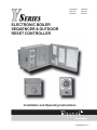
ELECTRONIC BOILER
SEQUENCER & OUTDOOR
RESET CONTROLLER
Installation and Operating Instructions
PN 240692 Rev. 9
Y–SERIES ELECTRONIC BOILER CONTROL
Installation and Operating Instructions
is a registered trademark of Underwriters Laboratories Inc.®
is a registered trademark of Underwriters Laboratories-Canada Inc. ®
Before operating this product, please read these instructions completely.
2
TABLE OF CONTENTS
Contents
Basics
Important Safety Instructions
Introduction
Concept of Operation
Optional Configurations
Control Features
Installation and Mounting
Mechanical Installation
Electrical Installation
Wiring: Power to Controller
Air Temperature Sensor
Water Temperature Sensor Installation
Hydronic Installations
Domestic Hot Water Installations
Pool Heating Installations
Field Wiring
Power Test
Control Familiarization
Sequence of Operation
Manual Override
Indicator Lights
Control Functions
Reset Ratio Chart
Circuit Board
Interior Jumper & Switches
Optional Controls
Replacement Parts List
System Start-Up Settings
Troubleshooting Guide
Warranty
Page
4
4
5
5
5
6
7
7
7
8
9
10
10
11
12
13
14
15
16
16
18
19
19
23
24
26
27
28
29
30
BASICS
Contents
Item
Quantity
Y–Series Boiler Control, Installed on Boiler(s)
Outdoor Temperature Sensor Assembly
Water Temperature Sensor Assembly
Optional Equipment
As Ordered
1
1
As Ordered
Check packaging for damaged or missing components.
IMPORTANT SAFETY INSTRUCTIONS
IMPORTANT NOTICE: These instructions are intended for use by qualified personnel who are
specifically trained and experienced in the installation of this type of equipment and related system
components. Installation and service personnel may be required by some states to be licensed. If your
state requires certification, be sure your contractor bears the appropriate license. Only qualified persons
shall attempt to repair this equipment. Repair must be according to these instructions.
WARNING: Improper installation, adjustment, alteration, service or maintenance may damage the
equipment, create a hazard resulting in asphyxiation, explosion, fire, electric shock, personal injury or
property damage, and will void the warranty.
CAUTION: MORE THAN ONE (1) SUPPLY SOURCE. THIS APPLIANCE HAS PROVISIONS
TO BE CONNECTED TO MORE THAN ONE (1) SUPPLY SOURCE. TO REDUCE THE RISK
OF ELECTRIC SHOCK, DISCONNECT ALL SUCH CONNECTIONS BEFORE SERVICING.
CAUTION: RISK OF ELECTRIC SHOCK. MORE THAN ONE (1) DISCONNECT SWITCH
MAY BE REQUIRED TO DE-ENERGIZE THE EQUIPMENT BEFORE SERVICING.
4
Thank you for selecting the Raypak Y–Series Electronic Boiler Control. It is our sincere hope that you will enjoy its
outstanding design, ease of use and energy saving features.
INTRODUCTION
The Y-Series Electronic Boiler Control (controller) is a microprocessor-based energy management system designed to
control either single or multiple stage-fired boilers. Ideally suited for use in hydronic heating and domestic hot water
supply applications, the Y-Series has been engineered with the flexibility and raw power to tame the most demanding
control situations. Utilizing a state-of-the-art PID control algorithm, the Y-Series minimizes operating costs by maximizing energy efficiency.
CONCEPT OF OPERATION
This controller is an outdoor reset control that is perfect for managing hydronic heating systems. Two temperature
sensors are used to control system response. One sensor is used to monitor the outdoor temperature, the other sensor is
used to regulate the temperature of the system water. By varying the temperature of the heating medium in response to
changes in the outdoor temperature, the Y-Series provides the ultimate in personal comfort and efficiency of operation.
The Y-Series controller is also well adapted to domestic hot water supply duty. By disabling the outdoor reset function, the
Y-Series behaves as an energy-wise boiler sequencer. With the ability to control up to eight firing stages, and such
features as a revolutionary "First-On, First-Off" lead-lag protocol, the Y-Series redefines "controlability" in domestic
water applications.
The controller is equipped with an energy-saving warm weather shutdown capability. When the outdoor temperature
rises above an adjustable "Outdoor Cutoff Temperature," the system automatically transitions to a dormant state. This
prevents the system from wasting energy trying to heat a building that is already at a comfortable temperature. Once the
outside temperature has fallen to the point that the system requires heat input to maintain the building temperature, the YSeries is reactivated and will hold the system temperature at the required point.
The Y-Series can also be equipped with an optional clocked alternate setpoint package. The alternate setpoint allows
control operation at an independent setpoint temperature and can be used either for night setback or preoccupancy boost.
An electromechanical 7-day timer switches the control between regular and alternate setpoint modes and can be set at two
hour activation intervals. See the section on the optional clocked alternate setpoint for details.
OPTIONAL CONFIGURATIONS
Y-2B
Y-3B
Y-4B
Y-5B
BASIC UNIT, NO OPTIONS
BASIC UNIT PLUS DIGITAL DISPLAY
BASIC UNIT PLUS NIGHT SETBACK OPTION
BASIC UNIT PLUS NIGHT SETBACK AND DIGITAL DISPLAY OPTIONS
PLEASE REGISTER
Before proceeding any further, please take a moment to complete the enclosed user registration form and mail a
copy to Raypak, Inc., Department Y–Series, 2151 Eastman Avenue, Oxnard, CA 93030
5
CONTROL FEATURES
The Y-Series sequence panel includes:
•
Standard Indicator Lights:
Stages 1 to 8:
Pump:
Call for Heat:
Control On:
Setting Error:
Sensor Error:
•
Red, indicates which stages are turned on.
Green, indicates that the pump circuit is energized.
Green, indicates that a call for heat signal is present.
Green, indicates outdoor temperature is below the Outdoor Cutoff Temperature
potentiometer setting and that the boiler will respond to a call for heat.
Red, indicates one or more of the on-board settings is incorrect.
Red, indicates that the Water or Outdoor Temperature Sensor has an out-of-range reading.
Adjustment Knobs:
Reset Ratio:
0.12:1 to 8:1; determines how much the micro-controller calculated Target
Temperature will change for a given outdoor temperature change.
Control Band:
1°F to 10°F; the temperature above or below the Target Temperature at which the boiler
turns off and on.
Pump Off Delay:
.
•
0 to 10 min.; determines when the pump shuts off after entering Outdoor Cutoff mode.
Outdoor Cutoff
Temperature:
32°F to 200°F; a warm weather shutdown feature. When the outdoor temperature
exceeds this setting, the boiler will not fire unless placed in manual override mode.
Outdoor Cutoff
Deadband:
1°F to 10°F; the number of degrees below the Outdoor Cutoff (O/C)
Temperature which causes the O/C to reset.
Boiler On Delay:
0 to 5 min.; sets the time interval between sequential boiler start ups.
Stage On Delay:
0 to 60 sec.; determines the time delay between stages turning on.
Max. Water Temp.:
70°F to 235°F; the maximum value that the Target Temperature is allowed to reach.
Set Point:
40°F to 220°F; the system output temperature desired when the outdoor temperature is
70°F or, in domestic water applications, the desired water temperature.
Logic Test Button, Jumper and Switches:
System Test Button (S1):
initiates micro self test which causes the status indicator lights to blink 5 times
indicating the micro-controller is functioning properly.
Last Stage Jumper (J2):
selects the last active stage used for boiler control.
First Stage #1 Selector (S2):
designates the first stage of each boiler in a multi-boiler system. Switch
position #1 should always be on.
Mode Selector (S3):
switch #1 selects either Manual or Auto Lead-Lag Mode. Switch #2 provides an
Outdoor Reset defeat. Switch #3 configures the Y–Series for Master/Slave ganged
operation. Switch #4 allows the Set Point to be set below 105°F.
Bypass Switches (S5):
allows user to turn on any stage(s) regardless of current settings and
conditions if, and only if, the pump relay is already activated.
6
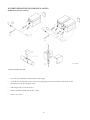
INSTALLATION AND MOUNTING
If the Y–Series Electronic Boiler Control was not mounted on the boiler by the factory, care should be taken to select a
suitable mounting location. The control should be mounted on a solid and permanent base. The control enclosure is
NEMA 3R rated, rainproof and sleet resistant, and can be mounted outdoors if required. The unit should be readily
accessible for maintenance and installation purposes, and should be mounted so that the indicating lights are at a height
and location convenient for viewing.
MECHANICAL INSTALLATION
Install the control within 10 feet of the boiler(s). The control must be mounted vertically with the conduit holes facing
downward. The conduit holes are sized to accommodate standard conduit fittings. If additional or larger conduit fittings
are required, the holes should be located on the bottom of the module.
Mount the control using the mounting bracket and appropriate 3/8” or 1/4” hardware in four (4) places.
A minimum of eighteen (18) inches clearance from the front, and six (6) inches clearance on all other sides is required for
service access. The hinged right side of the box should be installed with sufficient clearance (minimum 3” from the bolt
holes on the right side) to open the cover.
An electrical distribution sub-panel containing appropriate disconnect switches and surge suppressors is required at or near
the equipment location(s).
To access the control board, remove the interior front panel by unscrewing the four (4) decal panel fasteners.
INSTALL CONDUIT AS APPROPRIATE.
NOTE #1 : Shielded 18 gauge cable must be used to connect the sensors to the Boiler Control Module. The shielded
cable should be protected by conduit whenever possible.
NOTE #2 : 18 AWG - Stranded wire must be used for all connections to printed circuit board (PCB). Solid conductors
should not be used because solid wire conductors can cause excessive tension on contact pointS.
ELECTRICAL INSTALLATION
ELECTRICAL CHARACTERISTICS: 120 VAC, 60 Hz, 0.5A
120 VAC FEEDER CIRCUITS
Install a surge protection device sized appropriately for your installation at each module.
Install a separate disconnect means for each load. Use appropriately sized wire for equipment as defined by NEC and/or
local code. All primary wiring should be 125% of minimum rating.
It is strongly recommended that the Y-Series Electronic Control Module and the boiler(s) be supplied from the same power
source.
7
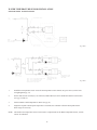
CHECK YOUR POWER SOURCE
Using a volt-ohm meter, check the following voltages at the circuit breaker panel:
BLACK
CIRCUIT
BREAKER
VOLT-OHM
METER
WHITE
GREEN
GROUND
A B
C
AC = 108 Volts AC Minimum, 132 Volts MAX
AB = 108 Volts AC Minimum, 132 Volts MAX
BC = Must be less than 1.0 Volts AC
WIRING: POWER SOURCE TO CONTROLLER
•
Observe polarity.
•
Observe proper wire colors while making electrical connections.
•
Provide an external surge suppressor capable of maintaining system integrity.
•
Provide overload protection and a disconnect means for equipment serviceability as required by local and state
code.
Conduit cannot be used as the ground. (There must be a “WIRED” ground.)
•
•
Very Important: A grounding electrode conductor shall be used to connect the equipment grounding
conductors, the equipment enclosures, and where the system is grounded, the grounded service
conductor to the grounding electrode.
GRN
WHT
120VAC
SUPPLY
HOT
RTN
GND
BLK
GRN
WHT
BLK
SPG
SINGLE POINT
GROUND
8
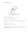
AIR TEMPERATURE SENSOR
Red (spare)
Red (connect)
Black (connect)
Fig. #9040
OUTDOOR AIR TEMPERATURE SENSOR
Outdoor Air Temperature Sensor Installation Notes:
•
Locate the sensor on the coldest side of building, usually the North or West side.
•
Install the sensor in a shaded area, out of direct sunlight.
•
Locate no higher than 2/3 up the side of the building, or between the 2nd and 3rd floor if the building is more than
three stories tall.
•
Do not locate under an overhang, near wall corners, near drafts from stacks, air-moving devices, windows, doors, or
balconies.
•
Shielded cable length run is not to exceed 300 feet.
•
Install with properly-sized conduit that contains no other wiring.
•
Observe proper wire colors.
•
The outdoor air temperature and water temperature sensors are identical and interchangeable. Both are equipped
with dual sensing elements. Connect only one red wire and the black wire to the sensor connecting points. The
second element is an installed spare.
9
WATER TEMPERATURE SENSOR INSTALLATION
HYDRONIC INSTALLATIONS
Fig. #9496
TYPICAL WATER SENSOR
•
The water sensor should be installed in the system supply.
•
Locate the water temperature sensor in the system piping just prior to the first boiler connections, on the
upstream side of the System Supply Loop.
•
Cable length must not exceed 300 feet.
•
Install in shielded conduit with no other wiring.
•
Observe wire colors.
10
WATER TEMPERATURE SENSOR INSTALLATION
DOMESTIC HOT WATER INSTALLATIONS
Y-Series Controller
Fig. # 9497.1
Air temperature sensor must be installed across air temperature sensor contacts. The sensor is not activated and can be
left stored in controller enclosure.
DOMESTIC HOT WATER APPLICATION SETUP PROCEDURE
1.
Install a 10,000 Ohm, 1/8 Watt resistor between pins 1 and 2 on P2 connector (see pg. 13), in place of
the Outdoor Air Temperature Sensor. The Outdoor Air Temperature will appear to be about 77°F.
2.
Set switch #2 (Outdoor Reset) to ON - 70°F Defeat, on S3. (See pg.s 15 and 23-24.)
3.
Set the Outdoor Cutoff Temperature to 200°F. (See pg. 21.)
4.
Adjust the Set Point to desired domestic hot water temperature. Controller will track the Set Point
Temperature. (See pg. 22.)
NOTE: The Outdoor Air Temperature sensor can be used as a replacement for the Water Temperature Sensor. Both
sensors are identical.
11
WATER TEMPERATURE SENSOR INSTALLATION
POOL HEATING INSTALLATIONS
Fig. # 9498
Fig. # 9499
1.
Install the air temperature sensor across the air temperature sensor contacts (P2, pins 1 and 2; see the field
wiring diagram on pg. 13).
2.
On the mode selector switch (S3), set switch #2 (Outdoor Reset) to ON to disable the outdoor reset function.
(See pg.s 15 and 23).
3.
Set the Outdoor Cutoff Temperature to 200°F. (See pg. 21.)
4.
Adjust the setpoint to desired pool temperature. Thereafter, the controller will track the setpoint and fire
heater stages as necessary.
NOTE: The Outdoor Air Temperature sensor can be used as a replacement for the Water Temperature Sensor, as both
sensors are indicated.
12
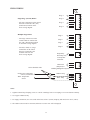
FIELD WIRING
P5
1
2
3
4
5
6
7
8
Stage 1
Single-Stage (On/Off) Boilers
Stage 2
- All stage connections on the control
board are connected at the {TH}
(Thermostat) location on the
boiler wiring diagram.
Stage 3
Stage 4
Multiple-Stage Boilers
1
2
3
4
5
6
7
8
Stage 5
- First stage connections on the
control board are connected at
the {TH} (Thermostat) location
on the boiler wiring diagram.
Stage 6
Stage 7
Stage 8
- Second (or third, etc.) stage
connections on the control
board are connected at the
locations shown on the
boiler wiring diagram.
P6
Pump Relay
Pilot Duty Only
2.5 Amp Max
250V Max
Thermostat
(Jumpered) or
Building Management System
Utilize Shielded Cable
Outdoor Air Temperature
Sensor (see NOTE 4)
Water Temperature
Sensor
1
2
P4
1
2
3
P1
1
2
3
4
Outdoor Temp
Water Temp
P2
Notes:
1. Tighten terminal strip clamping screws to 4 in-lbs. Breakage from over torquing is not covered under warranty.
2. Use copper conductors only.
3. For supply connections, use wires sized on the basis of 60°C (140°F) ampacity and rated a min. 90°C (194°F).
4. The outdoor sensor must be connected, otherwise a sensor error will be displayed.
13
INSTALLATION VERIFICATION PROCEDURE
REGISTER
Before proceeding any further, please verify that the user registration form has been completed and mailed.
MECHANICAL INSTALLATION
Verify that the mechanical installation has been completed in accordance with the instructions.
OUTDOOR AIR TEMPERATURE SENSOR
Verify that all Outdoor Air Temperature Sensor installation parameters have been met.
WATER TEMPERATURE SENSOR
Verify that the Water Temperature Sensor installation parameters have been met.
SYSTEM MODULE INSTALLATION
Verify electrical power wiring connections.
Verify electrical connection torque requirements.
Verify Outdoor Air Temperature Sensor wiring.
Verify Water Temperature Sensor wiring.
Verify Power Test has been completed successfully.
POWER TEST
Utilizing a Volt-Ohm-Meter (VOM) monitor the following on the controller for proper voltage levels. Check at
Terminal Block TB-1.
POWER TEST TABLE
From:
To:
Indication
TB pin 1
TB pin 2
108 VAC to 132 VAC
TB pin 1
Single Point Ground
108 VAC to 132 VAC
TB pin 2
Single Point Ground
less than 1 VAC
14
CONTROL FAMILIARIZATION
The System is configured using the circuit board jumpers and switches, and the front panel control potentiometers.
Open the front cover of the Boiler Control Box for access to the front panel. Remove the front panel to gain access to the
jumpers and switches on the Y-Series Electronic Boiler Control circuit board.
Refer to the Interior Jumper and Switches section of this manual (pg. 24) for detailed configuration instructions.
1.
Last Stage Selector. Install the jumper pot (J2) shunt bar in the position that corresponds to the total
number of stages to be controlled.
2.
First Stage Selector. Switch (S2); Place switches in the ON position corresponding to the first stage
of each boiler in the system. Switch position #1 should always be in the ON position.
3.
Mode Selector. Switch (S3) determines the following:
A. Switch #1, R/M
OFF - Manual Lead-Lag selection
ON - Automatic Lead-Lag selection
B. Switch #2, 70°F OFF
OFF - Outdoor Reset Enabled
ON - 70°F Defeat Enabled, Outdoor Reset Disabled-used for domestic water installations.
C. Switches #3 Master/Slave Option
OFF - Designates the Y-Series as a Master Control (Normal)
ON - Designates the unit as a slave (used for ganged Y-Series controls controlling 9 to 24 firing stages)
D. Switch #4, No Min Set Point Switch
OFF - Minimum allowable Set Point of 105°F to reduce potential of condensing the boiler.
ON - Set Point can be reduced to 40°F for special applications (i.e. water source heat pumps, etc.)
E. Switch #5 (reserved)
F. Switch #6 (reserved)
G. Switch #7 (reserved)
H. Switch #8 (reserved)
4.
Lead-Lag Selector, Rotary switch (S4) selects the lead stage for stage sequencing. (Applies only in manual
lead-lag mode when Mode Selector Switch (S3) Switch #1, is OFF) switch should point to first stage in multi
stage applications.
5.
Output Over-Ride Switch (S5) provides Manual Override of the system control. Switches #1 through #8 turn
on the corresponding relay and stage. Switch #9 turns on the pump circuit. The other stages are interlocked with Switch #9 and will not fire unless the pump is on. Switch #10 is not used.
6.
System Test Switch (S1) is a momentary switch which will cause status indicators to blink five times
then revert to normal indications. This tests the functions status of the micro-controller.
Reinstall the panel above indicator lights that cover the Y-Series Electronic Boiler Control Circuit board.
Refer to the CONTROL POTENTIOMETERS (KNOBS) section of this manual to set the initial system operating parameters. Set knobs to default values and fine tune if necessary.
15
SEQUENCE OF OPERATION
1. When the reset is enabled, the Y-Series Control continously monitors outdoor temperature using the outdoor
temperature sensor. When the outdoor temperature falls below the outdoor cutoff tempersture, the Control becomes
active and closes the primary pump relay, energizing the primary system circulating pump. The Control then monitors
the system supply water temperature. The microprocessor calculates an optimum target water temperature within
selectable limits of the control band, the setpoint, the reset ratio and the outdoor air temperature. If outdoor is reset is
disabled, the readings of the air sensor are not used in subsequent calculations. In either case, if the water temperature
falls below the the calculated target temperature the Control sends a call for heat to the lead unit (stage).
2. Upon a call for the heat the control closes the lead unit's thermostat (TH) circuit, which the energizes the lead unit's
circulating pump. After the flow switch has confirmed adequate flow, the ignition sequence is initiated and the unit
ignites at stage 1. The Control then sequences the units/stages in response to changes in the system to target differen
tial temperature, time away from target temperature, and temperature rate-of-change parameter as determined by the
P+I+D algorithems.
3. Additional stages (and units) are activated or deactivated as required in order to maintain or restore target system
water temperature. This Control uses "first on, last off" logic. As the system water temperature increases and begins to
approach target temperature, the Control deactivates the stages and heaters in reverse order of firing until the first
unit/stage fired is turned off. After the final stage of a given unit has been turned off, that unit's Economaster pump
control will continue to power the unit's circulating pump until a user-adjustable time delay has elapsed, thereby
extracting all available residual heat.
4. The Control stores firing command and system response data in the last five memory registers of the microprocessor.
On the next call for heat, the Control will modify the stored P+I+D data to optimize its own responses.
5. When the outdoor temperature exceeds the outdoor cutoff temperature, the Control enters warm weather shut-down
mode. The primary pump is turned off after a user-adjustable time delay, and the Control becomes dormant, until
outdoor temperatures again fall below the outdoor cutoff temperature.
MANUAL OVERRIDE
Internal Switch (S5) Output Override can be used to manually override the Micro-controller control as long as the
Electronic Boiler Control circuit board has 24 VAC power. See Output Over-Ride Switch (S5) above.
16
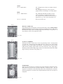
Y–SERIES ELECTRONIC BOILER CONTROL MODULE
Night Setpoint
Option
Digital Display
Option
Panel with Clock & LCD
Y-5 Configuration Shown
17
STAGES
1
2
INDICATOR LIGHTS
STAGE INDICATORS
The pump driver and each of the output stages' drivers has its own LED indicator. Each of
these LEDs is lit whenever the corresponding output relay is energized.
3
4
5
6
7
8
PUMP
PUMP INDICATOR
The Pump Indicator is illuminated whenever the pump circuit and pump relay are energized.
CALL FOR HEAT
CALL FOR HEAT INDICATOR
The Call For Heat Indicator is illuminated whenever a call for heat signal is present. In
most applications the thermostat connections on the control board (pg. 13) will be jumpered,
which will generate a continuous call for heat signal. The thermostat leads may also be
connected to a building management system which will produce the call for heat signal as
required.
CONTROL
ON
SETTING
ERROR
SENSOR
ERROR
CONTROL ON INDICATOR
The Control On Indicator illuminates if all settings and system conditions are such that the
control can function properly, and outdoor temperature cutoff temperature setting is less
than or equal to the outdoor temperature.
SETTING ERROR INDICATOR
The Setting Error Indicator is illuminated if there is a potentiometer, switch setting or jumper
placement error. Refer toTroubleshooting Guide "Setting Error LED Is On".
SENSOR ERROR INDICATOR
The Sensor Error Indicator is illuminated if either temperature sensor is out of range.
Steady on represents outdoor sensor failure, blinking represents water temperature sensor
error. See "Sensor Error LED On" in the Troubleshooting Guide (pg. 29).
18
CONTROL FUNCTIONS
RESET RATIO
The Reset Ratio setting determines how much the Target Temperature will increase as the
outdoor temperature drops. The Reset Ratio is expressed in the following manner:
X:Y
X - change in outdoor temperature
Y - change in Target Temperature
The first number in the ratio refers to the change in outdoor temperature in degrees Fahrenheit below outdoor cutoff while the second refers to the change in the computed Target
Temperature in degrees Fahrenheit. A Reset Ratio of 2:1 means that for every 2°F drop in
outdoor temperature from 70°F, the Target Temperature will increase 1°F.
For example:
Assume a Reset Ratio setting of 2:1 and a Set Point of 120°F.
When the outdoor temperature drops from 70°F to 20°F, the Target Temperature will increase from 120°F to 145°F. (With an outdoor to target ratio of 2:1, a 50°F outdoor temperature decrease results in a 25°F Target Temperature increase). See Reset Ratio Chart
(pg. 20) for more information.
The Reset Ratio is adjustable from 0.12:1 to 8.0:1.
Recommended Initial Setting for Reset Ratio is 1:1.
Suggested Settings
RADIATION
Typical
Temp @
Temp. @
Design Cond.
70°F
Reset Ratio Setpoint at Design Temp:
40°F
20°F
0°F
- 20°F
Standing
190
105
0.3:1
0.6:1
0.8:1
1.1:1
Convection or
Baseboard
200
105
0.3:1
0.5:1
0.7:1
0.9:1
Fan Coil - Heating
190
105
0.3:1
0.6:1
0.8:1
1.1:1
Fan Coil - Heat & Cool
140
105
0.9:1
1.4:1
2.0:1
2.6:1
Radiant Floor
120
105
2.0:1
3.3:1
4.7:1
6.0:1
Radiant Ceiling
120
105
2.0:1
3.3:1
4.7:1
6.0:1
The selection of the correct ratio is dependent on the initial temperature Set Point and the desired system water temperature. If the building
is too cold, move the ratio knob counter-clockwise one setting. After a change is made to the ratio, wait several days and evaluate the
comfort level before making another change.
19
RESET RATIO CHART
PUMP TURN-OFF DELAY
The Pump Turnoff Delay works in conjunction with the Outdoor Cutoff Temperature.
The Pump Turnoff Delay sets the delay between the time when the Outdoor Cutoff
Temperature is reached and the time when the pump is turned off.
The Pump Turnoff Delay is adjustable from 0 to 10 min.
Recommended Initial Setting for Pump Off Delay is 3 min
20
BOILER TURN-ON DELAY
In a multiple boiler system:
The Boiler Turn-On Delay sets the time delay before each additional boiler is turned on in
response to a call for heat. This delay starts when the preceding boiler is turned on.
The Boiler Turn-On Delay range is from 0 to 5 min.
Recommended Initial Setting for Boiler Turn-On Delay is 30 sec.
STAGE TURN-ON DELAY
The Stage Turn-On Delay sets the time delay before a new stage in a multistage boiler
configuration is turned on. This delay starts when the stage or boiler preceding the next
stage is turned on.
The Stage Turn-On Delay range is from 0 to 60 sec.
Recommended Initial Setting Stage for Turn-On Delay is 10 sec.
CONTROL BAND
The Control Band sets the maximum temperature above or below the Target Temperature
(which is determined by the embedded micro-controller) between which the system temperature may deviate. This provides a control deadband that limits the boiler from shortcycling.
The Control Band range is from 1°F to 10°F.
Recommended Initial Setting for Control Band is 3°F.
OUTDOOR CUTOFF DEADBAND
The Outdoor Cutoff Deadband sets the number of degrees below the Outdoor Cutoff where
the Outdoor Cutoff reset occurs.
The Outdoor Cutoff Deadband range is from 1°F to 10°F.
Recommended Initial Setting for Outdoor Cutoff Deadband is 3°F.
OUTDOOR CUTOFF TEMPERATURE
The Outdoor Cutoff sets the maximum outdoor temperature at which heat is desired. This
control sets the outdoor temperature above which the boiler bank is disabled. If the outdoor temperature increases beyond the Outdoor Cutoff setting, the Control ON LED turns
off and if there is no call for heat, the pump turn-off delay starts turning off the pump. If
the outdoor temperature falls below the Outdoor Cutoff minus the Outdoor Cutoff Deadband
the boiler bank will again be enabled.
The Outdoor Cutoff Temperature is from 32°F to 200°F.
Recommended Initial Setting for Outdoor Cutoff Temperature is 65°F.
21
MAXIMUM WATER TEMPERATURE
The Maximum Output Temperature is the system output high limit. This potentiometer
sets the maximum value the Target Temperature is allowed to reach regardless of other
operational settings or conditions.
The Maximum Water Temperature range is from 70°F to 235°F.
Recommended Initial Setting for Maximum Water Temperature is 180°F.
SET POINT
The Set Point is the system output temperature desired when the outdoor temperature is
70°F. This potentiometer may be set to any temperature from 40°F to 220°F, and is the
base-line setting for all operations. Note: Set Point cannot be below 105°F in normal
operation unless the No Min Set Point switch is in the ON position. (See Mode Selector
Switch). In domestic water supply applications, Set Point determines the water temperature maintained by the control.
The Set Point range is from 40°F to 220°F.
Recommended Initial Setting Set for Point is 120°F.
CAUTION: Setting the Set Point below 105°F may cause the boiler to condense which
will damage the boiler.
22
CIRCUIT BOARD
S5 MANUAL BYPASS
SWITCH
S4 MANUAL LEAD/
LAG
SELECTOR
SWITCH
MAINTENANCE
PLUG TEST
J2 LAST STAGE
SELECTOR
JUMPER
S1 SYSTEM
TEST
23
S3 MODE
SELECTOR
S2 FIRST STAGE
SELECTOR I.D.
INTERIOR JUMPER & SWITCHES
J-2
The Last Stage Selector Jumper (J2) is comprised of an eight (8) position jumper block. A shunt
bar jumper is placed in the position corresponding to the last active stage or boiler number. See
table below for examples of Jumper (J2) settings.
Fig # 9242
S-2
The First Stage Selector (Stage #1 ID) (S2) Switch is an eight (8) position switch, each switch
position corresponds to a Y-Series output stage. Turn ON the switch(s) that correspond(s) to
the FIRST stage of EACH boiler. Turn OFF the switch(s) that correspond(s) to the second (or
subsequent) stage(s), of EACH boiler.
(Switch #1 should always be on.) See the table below for examples.
Fig # 9245
S-3
The Mode Selector Switch (S3) is comprised of an eight (8) position dip switch with the
following functions:
AUTO
Sw #1 - Manual/Auto Lead-lag Selection Off - Manual lead-lag selection
On - Automatic lead-lag selection
OD off
Sw #2 - Outdoor Reset
Off - Outdoor Reset Enabled
"OD off"
On - Outdoor Reset Disabled. Use this setting
for applications like Domestic Hot Water
where outdoor air sensing is not required.
Fig # 9246
Note: The outdoor sensor must be connected in all modes, otherwise a sensor error will be
displayed.
24
SLAVE
Sw #3 - Master/Slave
Off - Designates the Y-Series as a Master Control
(Normal)
On - Designates the unit as a slave (used for
ganged Y-Series' controlling 9 to 24 firing stages)
DHW
Sw #4 - Outdoor Reset
Off - Minimum allowable Set Point of 105°F
reduces potential of condensensing the boiler.
On - Set Point can be reduced to 40°F for special
applications (e.g. water source heat pumps, etc.)
Sw #5 - 8 - Reserved
Reserved for future use.
S-4
MANUAL LEAD-LAG
The Lead-lag Selector Switch (S4) is a ten (10) position rotary switch. Switch positions
0 and 9 are not used. In manual lead-lag selection, the Lead-lag Selector is used to select
the lead boiler (stage). This is normally shipped from the factory set at position 1. If
auto lead-lag is used, do not adjust this switch.
Fig # 9244
S-5
OUTPUT OVERRIDE
The Bypass Switches: Switch (S5) is a ten (10) position dip switch. Switch position
10 is not used. The Bypass Switch enables the user to turn on any of the outputs
regardless of the current settings and conditions. Switch position 9 will turn on the
pump and the remaining eight switches will each override one of the output stages.
The pump switch and the output stages switches are interlocked such that the output
stages can only be turned on if the pump is on.
Fig # 9243
S-1
SYSTEM TEST
The System Test Switch (S1) is comprised of a single momentary push button switch.
When depressed it should cause the Status Indicators to blink five times. This test
sequence is an indication of the functioning status of the embedded micro-controller.
The Status Indicators revert back to their original indications after the test sequence is
completed.
Fig # 9247
25
OPTIONAL CONTROLS
Operational
Override Switch
Clock
Alternate
Setpoint Adjustment
Digital Display
Front Panel with Optional Alternate Setpoint
OPTIONAL ALTERNATE SETPOINT OPERATION
The Optional Alternate Setpoint can be used to establish an independent second set point for setback or
temperature boost requirements.
TRIPPERS
The electro-mechanical timer consists of 84 small switches called "Trippers" and a 7-day mechanical
clock. Each tripper represents a two-hour interval which determines set point selection as shown:
Tripper Pushed In = Normal Setpoint Operation
Tripper Pushed Out = Alternate Setpoint Operation
OPERATION OVERRIDE SWITCH
The Operation Override Switch is a three-position switch that determines if the trippers select the Setpoint,
of if either the normal Setpoint or Alternate Setpoint is continuously selected. The Operation Override
Switch can be set as follows
I - Alternate Setpoint selected continuously
L - Trippers determine selected set point
O - Normal Setpoint select continuously
NIGHT SETBACK OPTION:
MECHANICAL CLOCK (7-DAY)
Set to the appropriate local time.
Note: Turn the numbered dial clockwise to set time.
ALTERNATE SET POINT
Works independently of normal Setpoint. See discussion of Setpoint for details. Set to appropriate
setback or boost temperature. Turn the knob in the night setback option to the desired alternate setpoint.
DIGITAL DISPLAY OPTION:
LCD DISPLAY PANEL
The optional LCD display will indicate all values plus calculated target temperature and actual air and
water temperature.
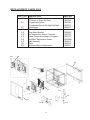
26
REPLACEMENT PARTS LIST
CALL OUT DESCRIPTION
1-C
PC Board Standard
PC Board w/ Night Set Back
2-C
Programmed Eprom
Programmed Eprom W/ Night Set Back
3-C
Transformer
1-S
Door w/Window
2-S
Side Mount Bracket
3-S
Air Temperature Sensor Complete
4-S
Water Temperature Sensor Complete
5-S
Air/Water Temperature Sensor
6-S
Well Assembly
1-N
Timer
2-N
Alternate Setpoint Adjustment
2-N
PART NO
006039F
006034F
005764F
006031F
005657F
N/A
005654F
005700F
005701F
005299B
004821F
006033F
006032F
1-N
2-S
3-C
1-C
5-S
2-C
4-S
1-S
5-S
6-S
3-S
27
SYSTEM START-UP SETTINGS
SYSTEM SETTING ENTERED ON DATE:
Front panel control potentiometers (knobs)
Reset Ratio:
______
Control Band:
Default Value: 1:1
Pump off Delay:
Default Value: 3°F
______
Outdoor Cutoff Deadband:
Default Value: 3 min.
Boiler on Delay:
______
Default Value: 3°F
______
Outdoor Cutoff Temp.:
Default Value: 30 sec.
Stage on Delay:
______
______
Default Value: 65°F
______
Max Water Temp.:
Default Value: 10 sec.
______
Default Value: 180°F
Set Point:
______
Default Value: 140°F
Optional Alternate Set Point
INTERIOR JUMPER & SWITCH SETTINGS:
Last Stage (J2)
Output ON Switch (S2)
Mode Selector Switch (S3)
Lead-Lag Switch (S4)
Bypass Switch (S5)
28
______
TROUBLESHOOTING GUIDE
In normal operating conditions, the Status Indications should be observed as follows:
Control Enabled
Sensor Error
Setting Error
ON (lit)
OFF
OFF
If the outdoor sensor fails and all other operating conditions remain the same, the control will remain on but it will
function as if the 70°F defeat mode is enabled. The following Status Indications should be observed:
Control Enabled
Sensor Error
Setting Error
ON (lit)
ON (lit)
OFF
If a different LED status is observed other than those described above, use the following detailed descriptions as a
guide:
If Control Enabled LED is OFF
Possible Causes:
1.
2.
3.
The output temperature sensor is out of range. The Sensor Error LED should be on. See below for details on the
Sensor Error LED.
There is a setting error. The Setting Error LED should be on. See below for details on the Setting Error LED.
The outdoor temperature is higher than or equal to the outdoor cutoff setting less the outdoor cutoff deadband
setting.
Sensor Error LED is ON or blinking ON/OFF once per second
Possible Causes:
LED ON steady: Outdoor (air) sensor is out of range.
LED blinking ON/OFF once per second: Output (water) sensor is out of range.
1. Examine wiring, ensure continuity from Y-Series to sensor(s).
2. Use a multimeter, measure resistance of sensor(s) compare with table below:
SENSOR RESISTA NCE A T VA RIOUS TEM PERA TURES
TEM P
Deg F
Res is tance (K)
40
26.11
50
19.90
60
15.31
TEM P
Deg F
130
140
150
Res is tance (K)
3.06
2.48
2.04
If all Okay, Replace Y-Series Boiler Control Board
3. If all okay, replace Y-Series Boiler Control Board.
70
11.88
80
9.30
90
7.33
100
5.83
110
4.66
120
3.76
160
1.69
170
1.40
180
1.17
190
0.98
200
0.83
210
0.70
Setting Error LED is ON
Possible Causes:
1. The Maximum Output Temperature setting is less than the Minimum Output Temperature setting.
2. The last stage selection is invalid. Either there is no stage selected or more than one stage is selected.
3. The first output stage is not selected as a stage #1. The first output stage should be set as a stage #1 in all cases.
4. In manual mode, the lead-lag selection is invalid (0 or 9).
5. In manual mode, the lead-lag selection is higher than the last stage.
6. In manual mode, the stage selected as the lead-lag is not set as a stage #1.
29
LIMITED WARRANTY
B6000, Y-Series, E-4 & Accessories
SCOPE OF WARRANTY
Raypak, Inc. ("Raypak") warrants to the original owner the Control System to be free from defects in materials and workmanship under
normal use and service for the applicable warranty period. In accordance with the terms of this Limited Warranty, RAYPAK will furnish
a replacement or repair, at our option, any defective part which fails in normal use and service during the applicable warranty period. The
replacement or repair will be warranted for only the unexpired portion of the original Warranty Period.
APPLICABLE WARRANTY PERIOD
The effective date of warranty coverage is the date of original installation, of the Control System, by a qualified electrician or by a
RAYPAK authorized service technician. The Applicable Warranty Period is one (1) year from the effective date.
WARRANTY EXCLUSIONS
This Limited Warranty does not apply:
1. if the control system is not properly installed by a qualified technician in accordance with manufacturer's installation
instructions, applicable codes, ordinances and good trade practices,
2. to damage or malfunctions resulting from failure to properly install, operate or maintain the system in accordance
with the manufacturer's instructions;
3. if the rating plate(s) or serial number(s) are altered, defaced or removed;
4. if the System is modified in any way or used with any non-factory authorized accessories or components;
5. to damage or failure from abuse, accident, act of nature, fire, flood, freezing or the like;
6. to accessories, rubber or plastic parts, light bulbs or glass parts;
7. if the System is moved from its original installation site; or if the original owner no longer owns the site or the System.
LABOR AND SHIPPING COSTS
This Limited Warranty does not cover labor costs for service, removal or reinstallation of any part nor shipping charges to or from
RAYPAK'S designated repair center or to or from the installation site. All such costs are your responsibility.
HOW TO MAKE A WARRANTY CLAIM
To make a warranty claim, promptly ship (postage prepaid) or carry the defective part to a designated RAYPAK Service Dealer or Service
Station in the United States, supplying proof of purchase and date of installation and the model and serial numbers. If you cannot locate a
dealer, contact RAYPAK'S Service Department at the address/telephone listed below. Raypak reserves the right at all times to inspect the
claimed defect and verify warranty coverage at its factory.
EXCLUSIVE WARRANTY - LIMITATION OF LIABILITY
This is the only warranty given by RAYPAK. No one is authorized to make any other warranties on Raypak's behalf. ANY IMPLIED
WARRANTIES, INCLUDING MERCHANTABILITY OR FITNESS FOR A PARTICULAR PURPOSE, SHALL NOT EXTEND
BEYOND THE APPLICABLE WARRANTY PERIOD SPECIFIED ABOVE. RAYPAK'S SOLE LIABILITY WITH RESPECT
TO ANY DEFECT SHALL BE AS SET FORTH IN THIS LIMITED WARRANTY. ANY CLAIMS FOR INCIDENTAL OR
CONSEQUENTIAL DAMAGES (INCLUDING DAMAGE FROM WATER LEAKAGE) ARE EXCLUDED. Some states do not
allow limitations on how long an implied warranty lasts, or for the exclusion of incidental or consequential damages, so the above limitation
or exclusion may not apply to you.
THIS LIMITED WARRANTY GIVES YOU SPECIFIC LEGAL RIGHTS, AND YOU MAY ALSO HAVE OTHER RIGHTS
WHICH VARY FROM STATE TO STATE.
We suggest you immediately complete the information below and retain this Limited Warranty Certificate in case warranty service is
needed.
RAYPAK, INC. SERVICE DEPARTMENT
2151 Eastman Avenue, Oxnard, California 93030
Telephone: (805) 278-5300 FAX (805) 278-5468
The following information must be provided when you write or call:
________________________________________________
Original Owner
_______________________________________________
Daytime Telephone Number
__________________________________________________________________________________________________
Complete Mailing Address
________________________________________________
City
State
Zip Code
_______________________________________________
Installation Site
________________________________________________
Model Number
_______________________________________________
Contractor/Installer
________________________________________________
Date of Installation
_______________________________________________
Serial Number
Raypak, Inc., 2151 Eastman Ave, Oxnard, CA 93030 (805) 278-5300 Fax (805) 278-5468
Litho in U.S.A.
www.raypak.com
Raypak, Inc., 2151 Eastman Avenue, Oxnard, CA 93030 (805) 278-5300 Fax (800) 872-9725
Raypak Canada Limited, 2805 Slough St., Mississauga, Ontario, Canada L4T 1G2 (905) 677-7999 Fax (905) 677-8036
Litho in U.S.A.