1
8F=AR8
OWNER'S
MANUAL
MODEL NO.
917.292360
£RI:IFTSMI:IN°
Caution:
Read and follow
all Safety Rules
and Instructions
Before Operating
This Equipment
5.0 HP
24 INCH TINE WIDTH
FRONT TINE TILLER
•
•
•
•
Assembly
Operation
Customer Responsibilities
Service and Adjustments
Repair Parts
Sears, Roebuck and Co., Hoffman Estates, IL 60179 U.S.A=
Safe Operation
SAFETY
RULES Powered
for Walk-Behind
Practices
TRAINING
•
•
•
Read the Owner's Manuat carefully. Be thoroughly
familiar with the controls and the proper use of the
equipment. Know how to stop the unit and disengage
the controls quickly.
Never allow children to operate the equipment. Never
allow adults to operate the equipment without proper
instruction.
Keep the area of operation clear of at! persons, particularly small children, and pets.
PREPARATION
=
•
°
•
•
o
•
•
-
Thoroughly inspect the area where the equipment is to
be used and remove all foreign objects.
Disengage all clutches and shift into neutral before
starting the engine (motor).
Do not operate the equipment without wearing adequate outer garments, Wear footwear that wilt improve footing on slippery surfaces.
Handle fuel with care; it is highly flammable.
Use an approved fuei container.
Never add fuel to a running engine or hot engine.
Filf fuel tank outdoors with extreme care. Never fill fuel
tank indoors.
Replace gasoline cap securely and clean up spilled
fuel before restarting.
Use extension cords and receptacles as specified by
the manufacturer for all units with electric drive motors
or electric starting motors.
Never attempt to make any adjustments while the
engine (motor) is running (except where specifically
recommended by manufacturer).
OPERATION
•
°
°
•
•
=
•
•
°
°
Do not put hands or feet near or under rotating parts.
Exercise extreme caution when operating on or crossing gravel drives, walks, or roads. Stay alert for hidden
hazards or traffic. Do not carry passengers.
After striking a foreign object, stop the engine (motor),
remove the wire from the spark plug, thoroughly inspect the tiller for any damage, and repair the damage
before restarting and operating the tiller.
Exercise caution to avoid slipping or falling.
If the unit should start to vibrate abnormally, stop the
engine (motor) and check immediately for the cause.
Vibration is generally a warning of trouble.
Stop the engine (motor) when leaving the operating
position,
Take atl possible precautions when leaving the machine unattended.
Disengage the tines, shift into
neutral, and stop the engine.
Before cleaning, repairing, or inspecting, shut off the
engine and make certain all moving parts have stopped.
Disconnect the spark plug wire, and keep the wire
away from the plug to prevent accidental starting.
Disconnect the cord on electric motors.
Do not run the engine indoors; exhaust fumes are
dangerous.
Never operate the tiller without proper guards, plates,
or other safety protective devices in place.
&
Rotary Tillers
•
°
Keep children and pets away.
Do not overload the machine capacity by attempting to
till too deep at too fast a rate.
•
Never operate the machine at high speeds on slippery
surfaces. Look behind and use care when backing.
Never allow bystanders near the unit.
Use only attachments and accessories approved by
the manufacturer of the filler (such as wheel weights_
counterweights, cabs, and the like).
Never operate the tiller without good visibility or light.
Be careful when tilting in hard ground. The tines may
catch in the ground and propel the titler forward, tf this
occurs, let go of the handlebars and do not restrain the
machine.
,
•
=
MAINTENANCE
•
•
o
•
AND STORAGE
Keep machine, attachments, and accessories in safe
working condition.
Check shear pins, engine mounting bolts, and other
bolts at frequent intervals for proper tightness to be
sure the equipment is in safe working condition.
Never store the machine with fuel in the fuel tank inside
a building where ignition sources are present, such as
hot water and space heaters, clothes dryers, and the
like. Allow the engine to cool before storing in any
enclosure.
Always refer to the operator's guide instructions for
important details if the tiller is to be stored for an
extended period.
- IMPORTANT
-CAUTIONS, 1MPORTANTS, AND NOTES ARE A MEANS
OF ATTRACTING ATTENTION TO IMPORTANT'OR
CRITICAL INFORMATION IN THIS MANUAL.
IMPORTANT: USED TO ALERT YOU THAT THERE ISA
POSSIBILITY OF DAMAGING THIS EQUIPMENT.
NOTE:
Gives essential information that will aid you to
better understand, incorporate, or execute a particular set
of instructions,
,i
i.. ii
,,,,
i
ml
portant safety precautions, It means
Look for this BECOMEALERT!!!
symbol to point out
imCAUTION!t!
YOUR
SAFETY IS INVOLVED.
plug wire and place wire where it canCAUTION:
Always plug
disconnect
not contact spark
in order tospark
prevent accidental starting when setting
up, transporting, adjusting or making
repairs.
.,..,qmH
i H
i.,,.,_
A WARNING
i
ii
i. i
A
The engine exhaust from this product contains chemicals known to the State of California to cause cancer, birth defects, or other
reproductive
harm.
i
i.i
i i
i
=
,,
H.,
CONGRATULATIONS on your purchase of a Sears Tiller,
It has been designed, engineered and manufactured to
give you the best possible dependability and performance.
PRODUCT
Should you experience any problems you cannot easily
remedy, please contact your nearest authorized Sears
Service Center/Department.
We have competent, welltrained technicians and the proper tools to service or repair
this unit.
HORSEPOWER:
5.0 HP
DISPLACEMENT:
12.57cu. in. (206cc)
GASOLINE
CAPACITY:
3 Quarts
Unleaded Regular
Please read and retain this manual. The instructions will
enable you to assemL:le and maintain_ your tiller properly.
Always observe _he "SAFETY RULES".
MODEL
NUMBER
SPECIFICATIONS
OIL (API-SF/SG):
CAPACITY: 20 oz,)
SAE 30 (Above 32°F)
SAE 5W-30 (Below 32°F)
SPARK PLUG :
Champion RJ19LM
(STD361458)
(GAP: .030 _;)
917,292360
SERIAL
NUMBER
MAINTENANCE
DATE OF
PURCHASE
A Sears Maintenance Agreement is available on this product. Contact your nearest Sears store for details.
THE MODEL AND SERIAL NUMBERS WILL BE
FOUND ON THE MODEL PLATE ATTACHED TO
THE RIGHT HAND ENGINE BRACKET.
CUSTOMER
YOU SHOULD RECORD BOTH SERIAL NUMBER
AND DATE OF PURCHASE AND KEEP IN A SAFE
PLACE FOR FUTURE REFERENCE.
AGREEMENT
RESPONSIBILITIES
,
Read and observe the safety rules.
o
Fotlow a regutar schedule in maintaining, caring for and
using your tiller.
-
Follow the instructions
under the "Customer
Responsibilities" and "Storage" sections of this Owner's
Manual.
IMPORTANT;
THIS UNIT IS EQUIPPED WITH AN INTERNAL COMBUSTION
ENGINE AND SHOULD NOT BE USED ON
OR NEAR ANY UNIMPROVED
FOREST-COVERED,
BRUSH-COVERED
OR GRASS COVERED LAND UNLESS THE
ENGINE'S EXHAUST SYSTEM IS EQUIPPED WITH A SPARK ARRESTER
MEETING APPLICABLE
LOCAL OR STATE
LAWS (IF ANY), IFASPARKARRESTERfSUSED,
IT SHOULD BE MAfNTAINED
IN EFFECTIVE WORKING ORDERBYTHE OPERATOR.
IN THE STATE OF CALIFORNIA
THE ABOVE IS REQUIRED BY LAW (SECTION 4442 OF THE CALIFORNIA
RESOURCES
CODE),
OTHER STATES MAY HAVE SIMILAR LAWS.
FEDERAL LAWS APPLY ON FEDERAL
SEE YOUR SEARS AUTHORIZED
SERVICE CENTER FOR SPARK ARRESTER.
REFER TO THE REPAIR
SECTION OF THIS MANUAL FOR PART NUMBER.
i,ilrr i ,,
LIMITED TWO YEAR WARRANTY
ON CRAFTSMAN
nu nil
I1,11
PUBLIC
LANDS.
PARTS
I
TILLER
For two (2) years from date of purchase, when this Craftsman Tiller is maintained, lubricated, and tuned up
according to the operating and maintenance instructions in the owner's manual, Sears will repair free of charge any
defect in material or workmanship.
This Warranty does not cover:
•
Expendable items which become worn during normal use, such as tines, spark plugs, air cleaners and belts.
o
Repahs necessary because of operator abuse or negligence, including bent crankshafts and the failure to
maintain the equipment according to the instructions contained in the owner's manual.
=
If this Craftsman Titler is used for commercial or rental purposes, this Warranty applies for only thirty (30) days
from the date of purchase.
WARRANTY SERVICE tS AVAILABLE BY RETURNING THE CRAFTSMAN TILLER TO THE NEAREST SEARS
SERVICE CENTER/DEPARTMENT IN THE UNITED STATES. THIS WARRANTY APPLIES ONLY WHILE THIS
PRODUCT IS IN USE IN THE UNITED STATES.
This Warranty gives you specific legal rights, and you may also have other rights which vary from state to state.
SEARS, ROEBUCK AND CO., Di817WA, HOFFMAN ESTATES, tL 60179
LE OF CONTE
SAFETY RULES ...........................................................
2
CUSTOMER RESPONSIBILITIES ..................... 3, 12-14
PRODUCT SPECIFICATIONS ...................................... 3
WARRANTY ..................................................................
3
ACCESSORIES .............................................................
5
ASSEMBLY ...............................................................
6-7
OPERATION ............................................................
8-11
MAINTENANCE SCHEDULE ..................................... 12
SERVICE & ADJUSTMENTS ................................ 14-17
STORAGE ...................................................................
18
TROUBLESHOOTING ................................................. 19
REPAIR PARTS-TILLER ....................................... 20-25
REPAIR PARTS-ENGINE ........................ . ............. 26-30
SERVICE/PARTS ORDERING .................... Back Cover
INDEX
A
Accessories .....................................
Adjustments:
Carburetor ............................... 17
Depth Stake .............................. 9
Handle Height ......................... 14
Tines .................................. 14-15
V-Belt ......................................
16
Wheels ......................................
9
Air Cleaner .................................... t3
B
Belt, V-:
Belt Guard ............................... 17
Repair Parts ............................ 21
V-Belt Replacement ................ 16
Fue!:
Filling Tank .............................
Storage ...................................
Type ........................................
Finish:
Maintenance ...........................
10
18
10
14
H
13
8
8
8
11
Lubrication:
Lubrication Chart .................... 12
Engine ..................................... 13
13
13
14
12
14
13
14
14
D
Depth Stake:
Adjustment ................................ 9
Repair Parts ............................ 22
E
Engine:
Air Cleaner ..............................
Cooling System .......................
Fuel Type ................................
Lubrication ..............................
Oil Levet ..................................
F
Handle:
Height Adjustment ................... 14
Repair Parts ............................ 20
C
Cooling System .............................
Controls:
Choke .......................................
Throttle ......................................
Tines .........................................
Cultivating .....................................
Customer Responsibilities:
Air Cleaner ..............................
Cooling System .......................
Finish ......................................
Maintenance Schedule ...........
Muffler .....................................
Oil Change ..............................
Spark Plug ..............................
Transmission ..........................
Oil Type ............................. 10,13
Repair Parts ....................... 26-30
Spark Plug .............................. 14
Starting ................................... 10
Stopping .................................... 9
Storage ................................... 18
Winter Operation ..................... 13
5
13
13
10
13
10
L
M
Muffler:
Maintenance ........................... 14
Spark Arrester ........................... 3
O
Oil:
Level ....................................... 10
Type ................................... 10,13
Operation:
Cultivating ............................... 11
Fill Fuel Tank .......................... 10
Starting Engine ....................... 10
Stopping Tines & Engine .......... 9
Tilling ........................................ 9
Tilling Hints ............................. 11
Tine Operation .......................... 9
Transporting Tiller ................... 10
Winter Operation ..................... 13
R
Repair Parts
Tiller ................................... 20-24
Engine ................................ 26-30
Rules for Safe Operation ................. 2
S
Service & Adjustments:
Carburetor ............................... 17
Handle Height ......................... 14
Tines .................................. 14-15
V-Belt ...................................... 16
Wheels ...................................... 9
Service:
Repair Parts ....................... 20-30
Service Record ....................... !2
Spark Plug:
Gap ........................................... 3.
Maintenance ........................... t4
Storage:
Fuel System ............................ 18
Tiller ........................................ 18
T
Tilling ..........................................
9,11
Tines:
Arrangement ...................... 14-15
Operation .................................. 9
Repair Parts ............................ 23
Replacement ........................... 15
Transmission:
Maintenance ........................... 14
Repair Parts ............................ 24
Troubleshooting ............................. 19
Transporting .................................. 10
W
Warranty ..........................................
3
Wheels:
Adjustments .............................. 9
Repair Parts ............................ 22
i,,
! iil!l
i
i
i¸, i,
ACCESSORIES
These accessories were available when the tiller was purchased. They are also available at most Sears Retai!
outlets, Catalog and Service Centers. Most Sears Stores can order repair parts for you when you provide the model
number of your tiller.
ENGINE
i,i, i!, ,,i ....
SPARK
PLUG
MUFFLER
AIR FILTER
i,ii
GAS CAN
ENGINE OIL
STABILIZER
iii
,i
III
TILLER
MAINTENANCE
,1111,uiii
ii,
BELT
iiii ,i II
TINES
CLEVIS PIN
ir,i,,,!, ii,
,
,
,11,11,11 ii ,,
ii
i
,
HAIRPIN CLIP
iiii
i=,1
m=
=
=-!i .¸ ,=
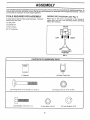
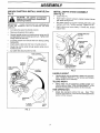
ASSEMBLY
Your new tiller has been assembled at the factory with exception of those parts left unassemb ed for shipping purposes. To
ensure safe and proper operation of your tiller all parts and hardware you assemble must be tightened securely. Use the
correct tools as necessary to insure proper tightness.
TOOLS REQUIRED
FOR ASSEMBLY
OPERATOR'S
A socket wrench set will make assembty easier. Standard
wrench sizes are listed.
(1) Utility knife
POSITION
(See Fig. 1)
When right or left hand is mentioned in this manual, it
means when you are in the operating position (standing
behind tiller handles).
(1) Screwdriver
FRONT
(1) Pair of pliers
(2) 1/2" wrenches
LEFT
RIGHT
OPERATOR'S
POSITION
FiG. 1
CONTENTS
OF HARDWARE
PACK
U
(1) Manual
_uli,,u,
n,
(1) Plastic Cable Clip
=
=uum,ilu
n
n=
,
=
O
(2) Carriage Botts 5/16-t8 UNC x 2-3/8 Gr. 5
(2) Flange Locknuts 5/16-18 UNC
©
(2) Hex Bolts 5/16-18 x lq/4
,
= L,
....
(2) Hex Nuts 5/16-18
_
(2) Lock Washers 5/16
........
iiii
UNPACK
Fig. 2)
ii ii iiii ii
i1,11111111
CARTON
ii
I _
ii
i1,1111
& INSTALL
i
iii
HANDLE
(See
Remove a{t packing from carton.
•
Secure handle cotumn to handle mount using two (2)
carriage bolts and two (2) flange tocknuts. Tighten both
flange Iocknuts securely.
•
Cut away carton and remove tiller from skid by pulling
backwards.
Insert plastic cable clip into hote in handle column.
•
•
iiiiii
ASSEMBLY
•
Loosen Nut "A:.
•
Insert stake support between engine bracket halves
with stake spring down.
•
Bolt stake support to engine brackets with bolts, lock
washers and nuts. Tighten securely. Tighten nut "A".
o
Depth stake must move freely. If it does not, loosen
support boit.
i
IMPORTANT:
WHEN UNPACKING ,_.NDASSEMBLING
TILLER, BE CAREFUL NOT TO STRETCH OR KINK
CABLE(S).
° Cut cable ties securing handle column.
•
i,i1,,
INSTALL DEPTH STAKE
(See Fig. 3)
i
staples when handling or disposing of
cartoning
CAUTION: material
Be careful of exposed
iiii
ENGINE BRACKET
HALVES
DEPTH STAKE
SUPPORT
Route tine control cable through ptastic cable clip on
handle column.
Cut cab{e ties securing tiller to skid,
TINECONTROL
DEPTH
STAKE
HANDLE
MOUNT
HEX BOLTS,
LOCK WASHERS,
AND HEX NUTS
T|NECONTROL
CABLE
HANDLE
COLUMN
SUPPORT
BOLT
FIG. 3
HANDLE
-
TILLING
o
HEIGHT
Handle height may be adjusted to better suit operator.
(See "HANDLE HEIGHT" in the Service and Adjustments section of this manual),
WIDTH
Tilling width may be adjusted to better handle your
tilling conditions (See "TINE ARRANGEMENT" in the
Service and Adjustments section of this manual),
TINE OPERATION
°
CARF
BOLT
FLANGE
LOCKNUT
FIG. 2
CABLE
CLIP
Check tine operation before first use. (See "FINE
OPERATION CHECK" in the Service and Adjustments
section of this manual).
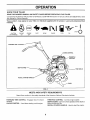
KNOW YOUR TILLER
READ THIS OWNER'S MANUAL AND SAFETY RULES BEFORE OPERATING YOUR TILLER.
Compare the illustrations with your tiller to familiarize yourself with the location of various controls and adjustments. Save
this manual for future reference.
u
These symbols
meaning.
iii
HII
lu
i
may appear on your Tiller or in literature supplied with the product.
Learn and understand
their
_
I',,I
CAUTION
OR WARNING
FORWARD TINE
ENGINE
ON
ENGINE
OFF
FAST
CHOKE
SLOW
FUEL
OIL
STOP O
CONTROL
CHOKE CONTROL
THROTTLE
CONTROL
DEPTH STAKE
TINE SHIELD
RECOIL STARTER HANDLE
FIG. 4
MEETS
ANSi
SAFETY
REQUIREMENTS
Sears tillers conform to the safety standards of the American National Standards Institute.
FORWARD TINE CONTROL - Engages tines in forward
direction.
CHOKE CONTROL - Used when starting a cold engine.
THROTTLE CONTROL - Controls engine speed.
DEPTH STAKE - Controls forward speed and the depth at
which the tiller wilt dig.
RECOIL STARTER HANDLE _ Used to start the engine.
OP
i
i ,i,_11
ii
,--
,
ii
The operation of any tiller can result in foreign objects thrown into the eyes, which can
result in severe eye damage. Always wear safety glasses or eye shields before starting
your tiller and while tilling. We recommend a wide vision safety mask over the spectacles
or standard safety glasses.
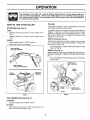
HOW TO USE YOUR
STOPPING
TILLING
TILLER
The speed and depth of tilling is regulated by the position
of the depth stake and wheel height,
(See Fig. 5)
TINES
,
Release forward tine control to stop forward mov_merit.
•
Release reverse tine control to stop reverse movement.
The depth stake should always be below the wheels for
digging. It serves as a brake to stow the tiller's forward
motion to enable the tines to penetrate the ground. Also,
the more the depth stake is lowered into the ground the
deeper the tines will dig.
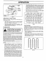
DEPTH STAKE (See Fig. 6)
ENGINE
-
Move throttle control to "STOP" position.
•
Never use choke to stop engine.
Adjust depth stake by removing the hairpin clip and clevis
pin. Change depth stake to desired position. Replace the
clevis pin and hairpin ctip.
•
TINE CONTROL
"OFF" (UP) POSITION
For normal tilling, set depth stake at the second or third
hole from the top.
WHEELS (See Fig. 6)
Adjust wheels by removing the hairpin clip and clevis pin.
Change wheel position. Replace the hairpin clip and clevis
pin.
For normal tilling,set wheels at the second or third hole
from the top.
HAIRPIN CLiP
AND CLEVIS PiN
DEPTH
STAKE
CHOKE
CONTROL
HAIRPIN CLIP
AND CLEVIS PIN
"WHEEL
FlG. 5
TINE OPERATION
(See Fig. 5)
FORWARD
•
Squeeze forward tine control to handle.
REVERSE
•
With forward tine control in "OFF" (up) position, pull
back and hold reverse tine control.
FIG. 6
RATION
TRANSPORTING
CA_
to within i/2 inch of top
]
of fuel tank to prevent spills and to
allow for fuel expansion. If gasoline is
accidentally spilled, move machine
away from area of spill. Avoid creating
any source of ignition until gasoline
vapors have disappeared.
Do not overfill. Wipe off any spilled of]
or fuel. Do not store, spill or use gasoline near an open flame.
...............
YOUR TILLER
i
ing, allow tiller engine and muffler to
cool. Disconnectsparkplugwire.
Drain
AUTION: Before lifting or transportgasoline from fuei tank.
l_
i
AROUND THE YARD
o Tip depth stake forward until it is held by the stake
spring.
=
Push titlerhandles down, raising tines off the ground.
•
Push or pull tiller to desired location.
AROUND TOWN
•
Disconnect spark plug wire.
.
Drain fue! tank.
,
Transport in upright position to prevent oil leakage.
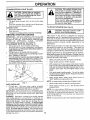
BEFORE STARTING
ENGINE
IMPORTANT:
BE VERY CAREFUL NOT TO ALLOW
DIRT TO ENTER THE ENGINE WHEN CHECKING OR
ADDING OIL OR FUEL. USE CLEAN OIL AND FUEL AND
STORE
IN
APPROVED,
CLEAN,
COVERED
CONTAINERS. USE CLEAN FILL FUNNELS.
FILL ENGINE
•
•
,
°
=
WITH OIL (See Fig. 7)
With engine level, remove engine oil filler plug.
Fill engine with oil to point of overflowing. For approximate capacity see "PRODUCT SPECIFICATIONS" on
page 3 of this manual.
Tilt tiller back on its wheels and then reqevet.
Check oil level. Refill to point of overflowing if necessary. Replace oil filler plug.
For cold weather operation you should change oil for
easier starting (See OIL VISCOSITY CHART" in the
Customer Responsibilities section of this manual).
To change engine oil, see the Customer Responsibilities section of this manual.
OIL
i
TO START
l_
CAUTION:
Keep
tine control
position when
starting
engine.in "OFF"
I
This engine on this product is designed for maximum
performance and life if operated with the choke (lXI) fully
open and the throttle control in the fast (,_) position. To
open the choke fully requires an engine warm-up period of
several seconds to several minutes, depending on the
temperature.
After starting the engine, first open the choke slowly until
the engine just begins to run smoothly. Then open the
choke in small steps, allowing the engine to accept small
changes in speed and load, until the choke is fully open.
During engine warm-up, the equipment can be operated.
When starting engine for the first time or if engine has run
out of fuel, it will take extra pulls of the recoil starter to move
fuel from the tank to the engine.
•
Make sure spark plug wire is properly connected.
"
Place throttle control in "FAST" position.
=
With engine fully choked, grasp recoil starter handle
with one hand and grasp tiller handle with other hand,
Pull rope out slowly until engine reaches start of com_
pression cycle (rope will pull slightly harder at this
point).
°
Pull recoil starter handle quickly. Do not let starter
handle snap back against starter. Repeat if necessary
in half choked position.
•
When engine starts, slowly move choke control to
"RUN" position as engine warms up,
_'_ _
OIL
FILLER
PLUG
ENGINE (See Fig. 8)
NOTE: A warm engine requires less choking to start.
FIG. 7
ADD GASOLINE
•
Fill fuel tank. Use fresh, clean, regular unleaded
gasoline. (Use of leaded gasoline will increase carbon
and lead oxide deposits and reduce valve life.)
IMPORTANT: ,/'.!HENOPERATING IN TEMPERATURES
BELOW 32°F (0°C), USE FRESH, CLEAN, WINTER GRADE
GASOLINE TO HELP INSURE GOOD COLD WEATHER
STARTING.
WARNING:
Experience indicates that alcohol blended
fuels (called gasohot or using ethanol or methanol) can
attract moisture which leads to separation and formation of
acids during storage. Acidic gas can damage the fuel
system of an engine while in storage. To avoid engine
problems, the fuel system should be emptied before
storage of 30 days or longer. Drain the gas tank, start the
engine and let it run until the fuel lines and carburetor are
empty. Use fresh fuel next season, See Storage section
of this manual for additional information. Never use engine
or carburetorcleaner products in the fuel tank or permanent
10_
damage may occur.
•
Move throttle control to desired running position.
-
Allow engine to warm up for a few minutes before
engaging tines.
NOTE: If at a high altitude (3000 feet) or in cold temperatures (below 32°F), the carburetor fuel mixture may need to
be adjusted for best engine performance. See "TO ADJUST CARBURETOR" in the Service and Adjustments
section of this manual.
NOTE: If engine does not start, see troubleshooting points.
=,=
=H=
=
•
OPERATION
H=
_----_
=H
=
=,H=
=
PARK
•
You will find tilling much easier if you leave a row
untilled between passes. Then go back over the entire
area at right angles (See Fig. 9), There are two reasons
for doing this. First, wide turns are much easier to
negotiate than about-faces. Second, the tiller won't be
pulling itself, and you, toward the row next to it.
•
Set depth stake and wheel height for shaNow tilling
when working extremely hard soil or sod, Then work
across the first cuts at normal depth.
PLUG
oo. .OL
,,,H=
HANDLE
FIG. 8
BREAKING
IN YOUR TILLER
Break-in your belt(s), putfeys and tine control before you
actually begin tilting.
•
Start engine, tip fines off ground by pressing handles
down and engage tine control to start tine rotation.
Allow tines to rotate for five minutes.
•
Check tine operation and adjust if necessary. See
"TINE OPERATION CHECK" in the Service and Adjustments section of this manual.
TILLING
FIG. 9
CULTIVATING
Cultivating is destroying the weeds between rows to prevent them from robbing nourishment and moisture from
the plants. At the same time, breaking up the upper layer
of soit crust will help retain moisture in the soil. Best
digging depth is 1" to 3".
HINTS
,,,, =,lll,,,,ll,=
....................
handling your tiller, start actual field
use with throttle in slow position (midAUTION:
way
betweenUntilyouareaccustomedto
"FAST" and "IDLE").
l_
H
ii i=liH= =
• You win probably not need to use the depth stake.
Begin by tipping the depth stake forward until it is heldby the stake spring.
_IJU,,,,H,,==
To help titler move forward, Iiff up the handles slightly (thus
lifting depth stake out of ground). To slow down the tiller,
press down on handles.
• Cultivate up and down the rows at a speed which will
allow tines to uproot weeds and leave the ground in
rough condition, promoting no further growth of weeds
and grass (See Fig. 10).
if you are straining or tiller is shaking, the wheets and depth
stake are not set properly in the soil being tilled. The proper
setting of the wheels and depth stake is through trial and
error and depends upon the soiFcondition. (The harder or
wetter the ground, the slower the engine and tine speed
needed. Under these poor conditions, at fast speed the tiJler
will run and jump over the ground).
A
\J
A properly adjusted tiller will dig with little effort from the
operator.
°
•
Tilling is digging into, turning over, and breaking up
packed soil before planting. Loose, unpacked soil
helps root growth. Best tilling depth is 4" to 6". A tiller
will also clear the soil of unwanted vegetation. The
decomposition of this vegetable matter enriches the
soil. Depending on the climate (rainfall and wind), it
may be advisable to till the soil at the end of the growing
season to further condition the soil.
\j"
FIG. 10
Soil conditions are important for proper titling. Tines witt
not readily penetrate dry, hard soil which may contribute to excessive bounce and difficult handling of your
tiller. Hard soil should be moistened before tilling;
however, extremely wet soil wilt "ball-up" or clump
during tii_ing. Wait until the soi! is less wet in order to
achieve the best results. When tiiling in the fail, remove
vines and tong grass to prevent them from wrapping
around the tine shaft and slowing your tillingoperation.
11
........................
iiii
1111111
IIIMIIIII
CUSTOMER
I IIIIII1'111I I I
I
I
III II
'
RESPONSIBILITIES
i
i,iiiii1,1,,i,iii
ii ii
,
i
MAINTENANCE
SCHEDULE
FiLL IN DATES
AS YOU COMPLETE
REGULAR SERVICE
SERVICE
Check Engine Oil Leve_
I_
_
............
DATES
.
i
Change Engine Oil
iiiiiiiNi
if
i ii,llll
ii
i
,i
Ill II
_t,2
i,,
Oil Pivot Points
5/'
,,,, ,,,,, ,., ,,
inspect Spark Arrester Muffler
inspect Air Screen
|
Vt
!_
Clean or Replace Air Cleaner Cartridge
1_2
Clean Engine Cylinder Fins
Replace Spark Plug
b/
1 - Change more often when operating under a heavy toad or in high ambient temperatures.
2 - Service more often when operating in dirty or dusty conditions.
GENERAL
RECOMMENDATIONS
LUBRICATION
CHART
The warranty on this tiller does not cover items that have
been subjected to operator abuse or negligence.
To
receive full value from the warranty, operator must maintain tiller as instructed in this manual.
/
Some adjustments will need to be made periodically to
properly maintain your tiller.
** ENGINE
All adjustments in the Service and Adjustments section of
this manual should be checked at least once each
season.
* TINE CONTROL
Once a year you should replace the spark plug, clean
or replace air filter, and check tines and belt for wear.
A new spark plug and clean air filter assure proper airfuel mixture and help your engine run better and last
longer.
BEFORE
EACH
USE
•
Check engine o" level.
•
•
Check tine operation.
Check for loose fasteners,
LUBRICATION
* SAE 30 OR t0W30 MOTOR OIL
** REFER TO CUSTOMER RESPONSIBILITIES
Keep unit well lubricated (See "LUBRICATION CHART").
12
"ENGINE
"SECTION.
CUSTOMER
RESPONSIBILITIES
i
J
I
accidental starting of engine.
Prevent fires! Keep the engine free of grass, leaves, spilled oil, or fuel. Remove fuel from tank before tipping
unit for maintenance. Clean muffler area of all grass, dirt, and debris.
Disconnect spark plug wire before performing any maintenance (except carburetor adjustment) to prevent
Do not touch hot muffler or cylinder fins as contact may cause burns.
&
i
Ill
,Ill
ENGINE
AIR CLEANER
Use only high quality detergent oil rated with API service
classification S F or SG. Select the oif's SAE viscosity grade
according to your expected temperature.
GRADES
,i
°F
-20
°
°c -3o•
0.1
.20o
TEMPERATURE
30° 32° _o
-too
RANGE
bo
ANTJCIPATED
60°
_oo
BEFORE
..........
ff.o_
.....................
_ooo
_oo
NEXT
30°
I,,lll II
(See Fig. 13)
Service air cleaner cartridge every twenty-five hours, more
often if engine is used in very dusty conditions.
*
Loosen air cleaner screws, one on each side of cover.
LUBRICATION
SAE VISCOSITY
I
40°
-
Remove air cleaner cover.
*
Carefully remove air cleaner cartridge. Be careful. Do
not allow dirt or debris to fall into carburetor.
o
Clean by tapping gently on a flat surface.
,
If very dirty or damaged, replace cartridge.
o
Clean and replace cover, Tighten screws securely.
iii ii
!
OIL CHANGE
III,,HI'IIII
CAUTION:
FIG. 11
NOTE: Although multi-viscosity oils (5W-30, 10W-30, etc.)
improve starting in cold weather, these multi-viscosity oils
wilt result in increased oil consumption when used above
32°F (0°C). Check your engine oil level more frequently to
avoid possible engine damage from running low on oil.
Petroleum
solvents,
I,II I I
such
cartridge. They may cause deterioraas kerosene,
are notto be
tion
of the cartridge.
Doused
not to
oilclean
cartridge. Do not use pressurized air to
clean or dry cartridge.
IIIN,,11,I,I_N,,i
Change the oil after the first two hours of operation and
every 25 hours thereafter or at least once a year if the tiller
is not used for 25 hours in one year.
i
3OVER
AIR
SCREW
Check the crankcase oil level before starting the engine
and after each five (5) hours of continuous use. Add SAE
30 motor oil or equivalent. Tighten oil filler ptug securely
each time you check the oil level.
................
AIR
CLEANER
CARTRIDGE
TO CHANGE ENGINE OIL (See Figs. 11 and 12)
Determine temperature range expected before oil change.
All oil must meet API service classification SF or SG.
•
Be sure tiller is on level surface.
•
•
,
°
Oil will drain more freely when warm.
Catch oil in a suitable container.
Remove drain plug.
Tip tiller forward to drain oil.
After oil has drained completely, replace oil drain plug
and tighten securely.
Remove oil filler plug. Be careful not to allow dirt to
enter the engine.
Refill engine with oil. See "CHECK ENGINE OIL
LEVEL" in the Operation section of this manual.
•
•
FIG. 13
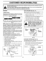
COOLING
SYSTEM
(See Fig. 14)
Your engine is air cooled. For proper engine performance
and tong life keep your engine clean.
•
Clean air screen frequently using a stiff-bristled brush,
°
Remove blower housing and clean as necessary.
°
Keep cylinder fins free of dirt and chaff.
CYLINDER
MUFFLER_._._._
FINS
BLOWER
\
OIL
DRAIN
PLUG
EVEL
OIL FILLER
PLUG
FIG. 12
FIG. 14
13
_L
..........
===H'HH=
='=
CUSTOMER
=m=
NSIBILITIES
=1 =
,,=,
MUFFLER
TRANSMISSION
Do not operate tiller without muffler. Do not tamper with
exhaust system. Damaged mufflers or spark arresters
could create a fire hazard. Inspect periodically and replace
if necessary. If your engine is equipped with a spark
arrester screen assembly, remove every 50 hours for
cleaning and inspection. Replace if damaged.
Your transmission is sealed and wilt only require lubrication
if it is serviced.
SPARK
CLEANING
PLUG
Replace spark plugs at the beginning of each tilling season
or after every 50 hours of use, whichever comes first. Spark
plug type and gap setting is shown in "PRODUCT SPECIFICATIONS" on page 3 of this manual.
•
Clean engine, wheels, finish, etc. of all foreign matter.
•
Keep finished surfaces and wheels free of all gasoline,
oil, etc.
•
Protect painted surfaces with automotive type wax.
We do not recommend using a garden hose to clean your
unit unless the muffler, air filter and carburetor are covered
to keep water out. Water in engine can result in a shortened
engine life.
, ,,,,,, ,11,
=
=
,'HH!
SERVICE AND ADJUSTMENTS
=
A
= ,,,,,,,m=,=, =H =
1,, ,,,,H H =
,
=
..................
CAUTION: Disconnect spark plug wire from spark plug and place wire where it cannot come into
contact with plug.
TILLER
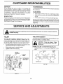
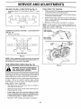
TO ADJUST
p
TINE ARRANGEMENT
HANDLE
HEIGHT
Your outer tines can be assembled in several different ways
to suit your tilling or cultivating needs.
(See Fig. 15)
Factory assembly has provided lowest handle height. Select handle height best suited for your tilling conditions.
Handle height will be different when tiller digs into soil.
gloves or other protection when han-
!_
,
If a higher handle height is desired, loosen the four nuts
securing handle panel to engine brackets.
..d.l.i,g tines..................
I
•
Slide handle panel to desired location.
•
Tighten the four nuts securely.
NORMAL TILLING - 24 INCH PATH (See Fig. 16)
* Assemble holes "A" in tine hubs to holes "B" in tine
shaft.
PIN
CLEVIS
ENGINE
BRACKETS
TINE
OUTER
HANDLE
PANEL
NUTS (ALSO 2
ON LEFT SlOE
OF TILLER)
HAIRPIN
CLIP
INNER TINE
FIG. 16
FIG. 15
14
D ADJUSTMENTS
FINAL CHECK "ON" POSITION
MID-WIDTH TILLING - 22 INCH PATH (See Fig. 17)
Assemble holes "A" in tine hubs to holes "C" in tine
shaft.
•
With fine control "ON" (held down to handle) push down
on handle to raise tines off the ground.
•
Stowly pull recoil starter handle while observing tines.
Tines should rotate forward.
=
if tines do not rotate, inner wire of control cable is too
loose. Loosen cable clip and purl cable up to remove
slack and retighten clip.
o
Recheck in "ON" position and adjust if necessary,
NOTE: if "ON" position check required adjustment, recheck "OFF '_'position adjustment to insure tines do not
rotate when control is "OFF" (up).
FIG, 17
NARROW TiLLINGICULTIVATING
TINE CONTROL
- 12-3/4 INCH PATH
(See Fig, 18)
0 Remove outer tines.
"OFF" POSITION
o_oo
(,
f o
ItO
o
o
o
CABLE
CLIP
j
CONTROL
CABLE
INNER TINES ONLY
FIG. 18
NOTE: When reassembling outer tines, be sure right tine
assembly (marked "R ) and left tine assembly (marked "L ')
are mounted to correct side of tine shaft.
TINE OPERATION
_G:
i _
_
from
CHECK
(See Fig, 19)
FIG. 19
Disconnect spark plug wire_
spark plug to prevent starting
while checking tine operation. .
=
For proper fine operation, tine control lever must be against
control body and all slack removed from inner wire of
control cable when control is in the "OFF" (up) position.
If lever and cable are loose, loosen cable clip at lower end
of cable.
Pull up on cable to remove slack, without
extending spring on end of cable, and retighten cable clip.
FINAL CHECK "OFF" POSITION
o
With fine control "OFF" (up), push down on handle to
raise tines off the ground.
,
Slowly pull recoil starter handle while observing tines.
Tines should not rotate.
•
If tines rotate, inner wire of control cable is too tight
which is extending lower spring and engaging tines.
Loosen cable clip and push down on cable only enough
to relieve spring tension. Tighten cable clip.
,
Recheck in "OFF" position and adjust if necessary.
15
nl
ii
SERVICE
,111111
.....................
AND ADJUSTMENTS
...........:...............................................
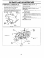
TO REMOVE
BELT GUARD
(See Fig. 20)
Remove cap nut and washer from side of belt guard,
•
Loosen (do not remove) fine shield nut on underside of
tine shield and cap nut on top of belt guard.
.
Pull belt guard out and away from unit.
-
Reptace belt guard by reversing above procedure. Be
sure slot in bottom of belt guard is under head of tine
shield bolt and all nuts are tightened securely,
CAP NUT
II
I I
TO REPLACE
,
BELT GUARD
HH
V-BELT
, ,i
i
(See Fig. 21)
Repiace V-belt if it has stretched considerably or if it has
cracks or frayed edges.
Belt guard must be removed to service belt. See "TO
REMOVE BELT GUARD" in this section of manual.
BELT REMOVAL
.
CAP NUT
AND WASHER
Remove V-belt from transmission purley first and then
from engine pulley.
BELT REPLACEMENT
-
Install new_V-belt to engine pulley first then to transmission pulley. 8e sure belt is positioned on inside groove
of both pulleys, inside all belt guides and rests on idler
pulley.
CHECK TINE OPERATION
•
See "T}NE OPERATION CHECK" in this section of
manuat.
REPLACE BELT GUARD
SHIELD
NUT
._
TINE
SHIELD
FIG. 20
BELT
GUIDE
BELT
GUARD
BOLT
/
ENGINE
TRANSMISSION
PULLEY
V-BELT
rDLER
PULLEY
FIG. 21
16
nl
SERVICE
InnnnHI,Hn'HHnl
II,n
AND ADJUSTMENTS
mH
HH
n l
ENGINE
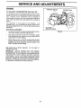
TO ADJUST
THRorrLE
U.KAGE
CARBURETOR
T.ROW,E
STOP
(See Fig. 22)
The carburetor has a high speed fixed jet and has been
preset at the factory and adjustment should not be necessary. However, minor adjustments may be required to
compensate for differences in fue!, temperature, altitude or
load. tf the carburetor does need adjustment, proceed as
follows.
?
The carburetor on this engine is low emission.
It is
equipped with a non-adjustable idle misture valve and an
idte speed adjustment screw. Only the idle speed screw is
adjustable.
IDLE RPM ADJUSTMENT
•
Aircleaner assembly must be assembled to the carburetor when making carburetor adjustments.
-
Start engine and allow to warm for five minutes. Make
final adjustments with engine running at idle and tine
control lever in "OFF' position.
•
With throttle control in "SLOW" positionrotate throttle
linkage counterclockwise and hold against stop while
adjusting idle speed adjusting screw to obtain 1750
RPM. Release throttle linkage.
High speed stop is factory
damage may result.
adjusted.
Do not adjust
IDLE SPEED
ADJUSTING SCREW
FIG. 22
or
IMPORTANT:
NEVER TAMPER
WITH THE ENGINE
GOVERNOR,
WHICH IS FACTORY SET FOR PROPER
ENGINE SPEED. OVERSPEEDING
THE ENG1NEABOVE
THE FACTORY
HIGH
SPEED
SETTING
CAN BE
DANGEROUS.
IF YOU THINK THE ENGINE-GOVERNED
HIGH SPEED NEEDS ADJUSTING,
CONTACT
YOUR
NEAREST
SEARS SERVICE
CENTER/DEPARTMENT,
WHICH HAS PROPER EQUIPMENT
AND EXPERIENCE
TO MAKE ANY NECESSARY
ADJUSTMENTS.
17
ENGINE
Immediatefy prepare your tiller for storage at the end of the
season or if the unit will not be used for 30 days or more.
CAUTION:
OIL
Drain oil (with engine warm) and replace with clean oil.
(See ENGINE n the Customer Responsfbl Itsessection of
this manual).
Never store the tiller with
where fumes may reach an open flame
gasoline in the tank inside a building
or spark.
Allow the engine to coot
before storing in any enclosure.
CYLINDERS
°
Remove spar_ plug.
*
TILLER
Pour 1 ounce (29 ml) of oil through spark plug hole into
cylinder.
-
Pull starter handle slowly several times to distribute oil.
°
Clean entire tilter (See "CLEANING" in the Customer
Responsibilities section of this manual).
-
Replace with new spark plug.
,
Inspect and replace belts, if necessary (See belt replacement instructions in the Service and Adjustments
section of this manual).
OTHER
•
Do not store gasoline from one season to another.
•
Lubricate as shown in the Customer Responsibilities
section of this manual.
=
Replace your gasoline can if your can starts to rust.
Rust and/or dirt in your gasoline will cause problems.
,
Be sure that alt nuts, bolts and screws are securely
fastened. Inspect moving parts for damage, breakage
and wear. Replace if necessary.
•
tf possible, store your unit indoors and cover it to give
protection from dust and dirt.
,
•
Touch up all rusted or chipped paint surfaces; sand
lightly before painting.
Cover your unit with a suitable protective cover that
does not retain moisture. Do not use plastic. Plastic
cannot breathe which allows condensation to form and
will cause your unit to rust.
ENGINE
IMPORTANT:
NEVER COVER TILLER WHILE ENGINE
AND EXHAUST AREAS ARE STILL WARM.
FUEL SYSTEM
IMPORTANT:
IT iS IMPORTANT TO PREVENT GUM
DEPOSITS FROM FORMING IN ESSENTIAL FUEL
SYSTEM PARTS SUCH AS THE CARBURETOR, FUEL
FILTER, FUEL HOSE, OR TANK DURING STORAGE,
ALSO, EXPERIENCE
INDICATES THAT ALCOHOL
BLENDED FUELS (CALLED GASOHOL OR USING
ETHANOL OR METHANOL) CAN ATTRACT MOISTURE
WHICH LEADS TO SEPARATION AND FORMATION OF
ACIDS DURING STORAGE. ACiDiC GAS CAN DAMAGE
THE FUEL SYSTEM OF AN ENGINE WHILE IN STORAGE.
•
Drain the fuel tank.
-
Start the engine and let it run until the fuel lines and
carburetor are empty.
=
Never use engine or carburetor cleaner products in the
fuel tank or permanent damage may occur.
Use fresh fuel next season.
"
NOTE: Fuel stabilizer is an acceptable alternative in
minimizing the formation of fuel gum deposits during storage. Add stabilizer to gasoline in fuel tank or storage
container. Always follow the mix ratio found on stabilizer
container. Run engine at least !0 minutes after adding
stabilizer to allow the stabilizer to reach the carburetor. Do
not drain the gas tank and carburetor if using fuel stabilizer.
18
, i i, i ,11
ilnlnlnl
i iii
inll,
Ull
,Ulllll,lln
TROUBLESHOOTING
iiii
ii ii
PROBLEM
Ulll
POINTS
Ullll
CAUSE
CORRECTION
n
Will not start
1. Out of fuel.
t.
Fill fuel tank.
2.
3.
4.
5.
6,
See "TO START ENGINE" in the Operation section.
Wait several minutes before attempting to start.
Clean or replace air cteaner cartridge.
Drain fuel tank and carburetor, and refill tank with fresh
gasoline,
Remove fueI tank and clean.
7,
8,
g.
Make sure spark plug wire is seated properly on plug.
Replace spark plug or adjust gap.
Make necessary adjustments.
Throttle control not set properly.
Dirty air cleaner.
Bad spark plug or improper gap.
Stale or dirty fuel.
Loose spark plug wire.
Carburetor out of adjustment.
t,
2,
3,
4,
5,
6,
Place throttle control in "FAST" position.
Clean or replace air cleaner cartridge.
Replace spark p'_ugor adjust gap,
Drain fuel tank and refiit with fresh gasoline,
Make sure spark plug wire is seated properly on p_ug.
Make necessary adjustments.
1.
2.
3.
4.
5.
Engineis ovedoaded.
Dirty air cleaner.
Low oil leveVdirty oil.
Faulty spark plug.
Oil in fuel.
6.
7.
Stale or dirty fuel.
Water in fuel.
t.
2.
3.
4.
5.
6.
7.
Set depth stake and wheels for shallower tilling.
Clean or reptace air cleaner cartridge.
Check oil level/change oil.
Clean and regap or change spark plug.
Drain and dean fuel tank and refill, and dean carburetor.
Drain fuei tank and refill with fresh gasoline.
Drain fuel tank and carburetor, and refill tank with fresh
gasoline.
Remove rue{ tank and clean.
Connect and tighten spark plug wire.
Ctean engine air screen.
Clean/replace muffler.
Make necessary adjustments.
ContactanauthorizedSearsServiceCenter/Departmentl
2.
3.
4.
5.
Eng{ne not"CHOKED"
Engine flooded.
Dirty air cleaner.
Waterin fuel.
6.
7.
8.
9.
CIogged fuel tank.
Loose spark plug wire.
Bad spark plug or improper gap.
Carburetor out of adjustment.
Hard to start
t.
2.
3.
4.
5.
6.
Loss of power
8.
g.
10.
11.
t2.
t3.
Engine overheats
properly.
CIogged fuel tank.
Spark plug wire loose.
Dirty engine air screen.
Dirty/dogged muffler.
Carburetor out of adjustment.
Poor compression.
8.
9.
10.
t 1.
12.
13.
!.
2.
3.
4.
5.
Low oil level/dirty oil.
Dirty engine air screen.
Dirty engine.
Partially pSugged muffler.
Improper carburetor adjustment.
1.
2.
3.
4.
5.
Check oil level/change oil.
Clean engine air screen.
Clean cylinder fins. air screen, muffler area.
Remove and clean muffler.
Adjust carburetor to ncher poslt_on.
1.
Ground too dry and hard.
2.
Wheels and depth stake incorrectly adjusted.
Moisten ground or wait for more favorable soil
conditions.
2. Adjust wheels and depth stake.
i1,1, i i Ul iii
Excessive bounce/
difficult handling
iiiiirrl
Soil balls up or clumps
1, Ground toowet.
,,,H,n'llHIIll
Engine runs but tiller
won't move
,i,
t.
2.
3.
U l ml
I lll,
I
i
ii ii ii i iiii ii iiii1,11iii
ii
ii
t.
Wait for more favorable soil conditions.
I.
2.
3,
Engage tinecontrol.
Inspect!adjust V-belt.
Inspect V-be_t.
, lUl
Tine control is net engaged.
V-be}t not correctly adjusted.
V-belt is off pulley(s).
i i
Engine runs but labors
when ti!_ing
1, TiIting too deep.
2, Throttle control not properly adjusted,
3, Carburetor out of adjustment.
1, Set depth stake for shal{ower tilling.
2, Check throttle control setting.
3, Make necessary adjustments,
19
_
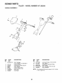
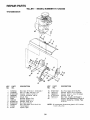
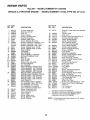
REPAIR PARTS
TILLER
HANDLE
-- MODEL
NUMBER
917,292360
ASSEMBLY
14
2
6
10
1
13
,
12
KEY
NO.
PART
NO.
t
STD533125
2
3
4
5
6
7
8
137118
152094
9266R
3066J
151229
12000027
154805
DESCRIPTION
KEY
NO.
9
10
11
12
13
14
Bolt, Carriage
5/16-18 UNC x 2-1/2Grade 5
Panel, Control
Assembly, Handle Column
Grip, Handle
Cable, Tine Control
Lever, Control, Tine
Ring, Clip
Pin, Pivot
PART
NO.
73970500
121145X
110514X
98000129
STD533107
1200059
NOTE:
2O
DESCRIPTION
Locknut, Flange 5/16-18 UNC
Clip, Cable
Assembly, Panel and Tube
Nut, Flange
Bolt, Carriage 5/16-18 x 3/4
Ring, Retainer
Ati component dimensions given in U.S. inches.
1 inch = 25_4 mm
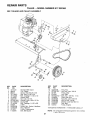
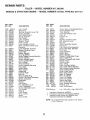
REPAIR PARTS
TILLER
BELT GUARD
- - MODEL
NUMBER
917.292360
AND PULLEY ASSEMBLY
21
3
2O
19
14
18
KEY
NO.
t
2
3
4
5
6
7
8
9
10
11
12
13
14
15
PART
NO,
121313X
9484R
86777
74770812
72140404
121463X
104213X
STD551025
131158X417
72140405
9180R
23230506
12000028
151223
110528X
17
DESCRIPTION
Bracket, Bett Guard
Clip, Plated
Screw, Hex #10-24 X ,50
Bolt, Hex 1/2-20 x 3/4
* Bolt, Carriage 1/4-20 x 1/2
Keeper, Belt
Nut, Cap t/4- 20
* Washer 9/32 x 5/8 x 16 Ga,
Guard, Belt
Bolt, Carriage 1/4-20 x 5/8
V-Belt
* Screw, Set, Socket, Headless
Ring, Retainer
Pulley, Transmission
Bolt, Belt Guard
KEY
NO.
PART
NO,
16
17
18
t9
20
21
22
23
24
25
26
12000036
STD54t237
9!78R
674A30
STD523712
106968X
73350500
73220400
10040400
109227X
130812
*STANDARD
NOTE:
21
DESCRIPTION
Ring, Klip
* Nut, Hex, Jam 3/8-16
Pulley, Idler
Arm, Idler
* Bolt, Hex 3/8-16 x 1-1/4
Shaft, IdterArm
Nut, Hex, Jam 5/16-18
Nut Fin Hex 1/4-20
Washer Lock Hvy Hlcl 1/4
Pad, Idler
Pulley, Engine
HARDWARE--
PURCHASE
LOCALLY
Aft component dimensions given in U.S. inches.
1 inch = 25.4 mm
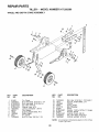
REPAIR PARTS
TILLER - - MODEL NUMBER 917.292360
WHEEL AND DEPTH
STAKE ASSEMBLY
10
/
4
4
<-
7
17
2O
19
18
t6
17
KEY
NO.
PART
NO.
1
2
3
4
5
6
7
8
9
I0
!1
9194R
74760520
STD523107
STD541031
STD551131
73800600
4921H
1952J
122233X
326J
74780628
DESCRIPTION
KEY
NO.
PART
NO.
Pin, Clevis
Bolt, Hex Head 5/16-18 x 1-I/4
Bolt, Hex Head 5/16-18 x 3/4
Nut, Hex 5/16-18
Washer, Lock 5/16
Locknut, w/washer 3/8-t6
Clip, Hairpin
Support, Depth Stake, R.H.
Stake, Depth
Pin, Clevis
Bolt, Fin, Hex 3/8-16 x 1-3/4
12
13
14
15
16
17
18
19
20
21
22
74760524
1951J
120958X
5388J
121117X
9188R
STD551037
9190R
STD541437
74760516
73800500
NOTE:
22
DESCRIPTION
Bolt, Hex 5/16-18 x 1-1/2 Grade 2
Support, Depth Stake, L.H.
Washer
Spring, Stake
Bolt, Shoulder
Wheel
Washer 13/32 x 13/16 x 11 Gauge
Bracket, Wheel
Locknut, Crown 3/8-16
Bolt, Hex Head 5/16-18 x 1
Locknut, w/insert 5/16-18
All component dimensions given in U.S. inches.
1 inch = 25.4 mm
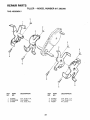
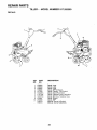
REPAIR PARTS
TILLER
- - MODEL
NUMBER
917.292360
TINE ASSEMBLY
2
3
/
2
/
6
6
6
KEY
NO.
1
2
3
PART
NO.
674A66
STD624008
674A64
DESCRIPTION
KEY
NO.
4
5
6
Tine, Outer, R.H.
Clip, Hairpin
Tine, Inner, R.H.
23
PART
NO.
674A63
674A65
4929H
DESCRIPTION
Tine, Inner, L.H.
Tine, Outer, L.H.
Pin, Clevis
REPAIR PARTS
TILLER
-- MODEL
NUMBER
917.292360
TRANSMISSION
20
3
5
7
t4
14
p
15
8
10
14
12
KEY
NO.
PART
NO.
1
2
3
5
6
7
8
9
10
11
12
14
74760524
74780652
STD551037
73800600
9056R417
!949J
110519X
STD551131
STD54!031
74760544
151222
9173R
DESCRIPTION
KEY
NO,
PART
NO,
Boit, Hex 5/16-18 x 1-1/2 Grade 2
Bolt, Fin, Hex 3/8-16 x 3-1/4
Washer 13/32 x 13/16 x 11
Locknut, w/washer 3/8-16
Shieid, Tine
Bracket, Engine, R.H.
Bracket, Engine, L.H.
Washer, Lock 5/t6
Nut, Hex 5/16-18
Bott, Hex Head 5/16-18 x 2-3/4
Transmission
Spacer, Split
15
16
17
18
19
20
STD541431
19091412
19092016
STD551125
74610412
.......
DESCRIPTION
Nut, Hex, Keps 5/16-18 UNC
Washer 9/32 x 7/8 x t2 Gauge
Washer 9/32 x I-1/4 x 16 Gauge
Washer, Lock 1/4
Bolt, Hex 1/4-28 x 3/4 Grade 5
Engine, (See Breakdown) Briggs &
Stratton, Model No. 137202, Type
0714-A1
NOTE: All component dimensions given in U.S. inches.
1 inch = 25.4 mm
24
REPAIR PARTS
TILLER
- - MODEL
NUMBER
917.292360
DECALS
10
KEY
NO.
1
2
3
4
5
6
7
8
9
10
---
PART
NO.
158094
158093
158005
158006
137539
120431X
110719X
120075X
272931
272630
158213
158214
DESCRIPTION
Decal, Logo
Decal, Logo
Decal, Logo
Decal, 5HP/24 Sears
Decal, Caution, Tine Control
Decai, Hand Placement
Decal, Operation and Lubrication
Decal, Warning, Rotating Tines
Decal, Engine
Decal, 5HP
Manual, Owner's(English)
Manual, Owner's(Spanish)
25
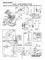
REPAIR PARTS
TILLER - - MODEL NUMBER 917,292360
BRIGGS
& STRATTON
ENGINE
- - MODEL
NUMBER
137202,TYPE
NO. 0714-A1
14
308
383
306
5_
iii
7
36
35
ii_
_
40 529
10
456
528
IIHI
i
26
613
81
22
i!
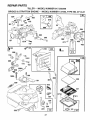
REPAIR PARTS
TILLER
BRIGGS
& STRATTON
- - MODEL
NUMBER
ENGINE - - MODEL
917.292360
NUMBER
137202,TYPE
NO. 0714-A1
52
433
!
53S
!91
209
916
967
181
621
204
223
27
971
REPAIR PARTS
TILLER
BRIGGS
& STRATTON
- - MODEL
ENGINE
NUMBER
- - MODEL
"k"REQUIRES SPECIAL TOOLS
TO INSTALL. SEE REPAIR
INSTRUCTION
MANUAL.
73
917.292360
NUMBER
137202,
TYPE
NO. 0714-A1
23
24
200
3O4
307
7
52
_9
3
163
65
_
373
%
F
55
28
515
459
REPAIR PARTS
TILLER - - MODEL NUMBER 917.292360
BRIGGS
KEY PART
NO. NO.
1
2
3
5
7
8
9
10
12
497144
399268
299819
214040
272157
495774
27549
94621
270080
270125
270126
t3
94221
14 94679
15 94916
16 492088
94388
18 494044
19 495660
20 294606
21 66768
21A 399195
22 94980
23 399673
24 222698
25 298904
298905
298906
298907
26 298982
299742
298983
298984
298985
27 26026
28 298909
298908
29 299430
390459
30
32
33
34
35
36
37
225183
94699
211119
261044
260552
26478
222443
& STRATTON
ENGINE
-- MODEL
NUMBER
KEY PART
NO. NO.
DESCRIPTION
Cylinder Assembly
Bushing, Cylinder
* Sea!, Oil
Head, Cylinder
* Gasket, Cylinder Head
Breather Assembly
* Gasket, Valve Cover
Screw, Breather Mounting
* Gasket, Crankcase, Standard .015"
* Gasket, Crankcase .005" Thick
* Gasket, Crankcase .009" Thick
Screw, Cylinder Head 2-3/32"
Screw, Cylinder Head 2-15/32"
Plug, Oil Drain
Crankshaft
Key, Woodruff
Cover Assembly, Crankcase
Bushing, Crankcase Cover
* Seal, Oil
Plug, Oil Filler
Plug, Oil Fill
Screw, Cover Mounting
Flywheel, Magneto
Key, Flywheel
Piston Assembly, Standard Size
Piston Assembly .010" Oversize
Piston Assembly .020" Oversize
Piston Assembly .030"Oversize
Ring Set, Piston, Standard Size
Ring Set, Piston, Standard, Chrome
Ring Set, Piston .010" Oversize
Ring Set, Piston .020" Oversize
Ring Set, Piston .030" Oversize
Lock, PistonPin
Pin Assembly, Piston, Standard
Pin Assembly, Piston .005" Over
Rod Assembly, Connecting
Rod Assembly, Connecting
,020" Undersize Crankpin Bore
Dipper, Connecting Rod
Screw, Connecting Rod
Valve, Exhaust
Valve, Intake
Spring, Intake Valve
Spring, Exhaust Valve
Guard, Flywheel
!37202,TYPE
NO. 0714-A1
DESCRIPTION
40
93312
Retainer, Intake Valve and Exhaust
Spring
Tappet, Valve
Gear, Cam
*** Gasket, Carburetor Mounting (2)
Housing, Rewind Starter
Pulley, Rewind Starter
Spring, Rewind Starter
Rope, Rewind Starter
(Cut to Required Length)
insert, Starter Handle
Handle, Rewind Starter
Screw, Housing Mounting
Screen, Rotating
Lock, Screw
Carburetor Assembly
Screw, Throttle Valve to Shaft
Throttle, Carburetor
Shaft and Lever, Throttle
Valve and Shaft Group, Choke
Spring, Choke
Carburetor Overhaul Kit
Screw, Hex Head
Plug, Welch
Plug, Welch
Jet, Pilot
Spring, Throttle Adjustment
Screw and Collar
Screw, Machine, Round Head
Base, Air Cleaner
*** Gasket, Air Cleaner Mounting
Tank Assembly, Fuel
Cap, Fuet Tank
Screw, Fuel Tank
Screw, Fuel Tank Mounting I-3/4"
*** Gasket, Fuel Tank to Carburetor
Guide, Air
Link, Governor
Link, Throttle
45
46
52
55
56
57
58
260642
212733
273113
497442
281504
263074
280399
59
60
65
73
81
90
95
96
97
108
111
121
124
127
127A
147
152
153
154
161
163
180
181
190
190A
t91
200
201
202
396892
393152
94686
225176
222263
498298
93499
223793
490048
497230
262715
495606
94913
220352
223789
231955
260575
490589
93527
492797
271935
495405
494559
94924
94919
272489
223886
262280
262270
*
**
***
Included in Gasket Set (495603)
Included in Carburetor Overhaul Kit (495606)
Included in both Gasket Set (495603), and
Carburetor Overhaul Kit (495606)
NOTE: AIt component dimensions given in U.S. inches
1 inch = 25.4 mm
29
REPAIR PARTS
TILLER
BRIGGS
KEY PART
NO. NO.
202A
203
204
205
208
209
216
219
220
222
223
224
262470
280720
222962
231520
262279
262948
262359
494845
221551
490649
223455
93491
227
230
256
300
304
305
306
307
308
332
333
334
337
346
356
358
363
373
383
392
393
394
414
432
433
434
435
455
456
459
467
515
524
490374
94927
223813
393615
495759
94786
224820
94680
224738
94877
397358
93414
802592
94896
398808
495603
19069
92987
89838
262328
225058
272538
220982
221377
93265
213963
93141
225121
225257
281505
280715
263073
271485
& STRATTON
= - MODEL
ENGINE
NUMBER
- - MODEL
917.292360
NUMBER
KEY PART
NO, NO.
DESCRIPTION
Link, Control
Belt Crank
Bushing, Governor Lever, Flat
Screw, Shoulder
Rod, Speed Control
Spring, Governor
Link, Choke
Gear, Governor
Washer, Thrust
Panel, Control
Lever, Governor Control
Rivet, Governor Control Lever
Mounting
Lever Assembly, Governor
Washer, Governor Lever
Crank, Bel!
Muffler, Exhaust
Housing, Blower
Screw, Btower Housing Mounting
Shield, Cylinder
Screw, Cylinder Shield
Cover, Cylinder Head
Nut, Flywheel
Armature Group
Screw, Armature Mounting
Plug, Spark
Screw, Seres
Wire, Ground
Gasket Set
Flywheel Puller
Nut, Hex
Wrench, Spark Plug
Spring, Fuel Pump Diaphragm
Screen, Carburetor
** Diaphragm
Washer
Cap, Spring
Pin, Diaphragm Cover
Cover, Diaphragm
Screw, Diaphragm Cover
Cup, Starter
Retainer
Pawt, Starter
Knob, Control
Spring
Ring, Oil Ret.
526
527
528
529
535
536
542
552
562
592
608
6!1
612
613
614
616
621
623
634
635
676
679
680
741
851
869
870
871
916
966
967
968
969
971
987
995
10t2
1036
94914
223786
231550
67838
491435
494279
94897
231079
94907
231978
497830
231068
391813
93935
93306
495243
396847
94943
271853
66538
393757
270382
221839
262992
493880
211787
211172
262001
63709
280321
492797
491588
495872
490073
94902
398970
497195
490507
499344
RPM Settings:
*
**
***
Included in
Included in
Included in
Carburetor
NOTE:
3O
137202,TYPE
NO. 0714-A1
DESCRIPTION
Screw, Sems, Tank Bracket Mount.
Clamp, Breather Tube
Tube, Breather
Grommet, Breather Tube
Fitter, Air
Cleaner, Air
Screw
Bushing, Governor Crank
Bolt, Governor Lever
Nut, Hex
Starter Assembly, Rewind
Pipe, Fuel
Fuel Pipe and Clip Assembly
Screw, Hex Head, Shoulder
Pin, Cotter
Crank, Governor
Switch, Stop
Screw, Shoulder
Washer, Throttle Shaft, Foam
Elbow, Spark Plug
Deflector, Exhaust, Side Outlet
Washer, Foam
Washer, Brass
Gear, Timing
Cable Terminal, Ignition
Seat, Intake Valve, Standard
Seat, Exhaust Valve, Standard
Guide, Exhaust Valve
Guide, Intake Valve
Rack, Gear Control
Base, Air Cleaner
Filter, Air Cleaner
Cover, Air Cleaner
Screw, Air Cleaner
Screw, Hex Head
Seal, Throttle Shaft
Lever, Bracket Assembly
Retainer, Link
Label, Kit-Emission
Low: 1200-1600,
High: 3500-3700
Gasket Set (495603)
Carburetor Overhaul Kit (495606)
both Gasket Set (495603), and
Overhaul Kit (495606)
All component dimensions given in U.S. inches
t inch = 25.4 mm
NOTES
31
OWNER'S
MANUAL
MODEL NO.
917.292360
£RIIFTSMAN°
5.0 HP
24 INCH TIN
DTH
FRONT TINE TILLE
Each tiller has its own model number.
number.
Each engine has its own model
The model number for your tiller will be found on a plate attached to the
right hand engine bracket.
The model number for your engine witl be found on the blower housing of
the engine.
IF YOU NEED
REPAIR SERVICE
OR PARTS:
FOR REPAIR SERVICE, CALL
THIS TOLL FREE NUMBER:
1-800-4-REPAIR
(1-800-473-7247)
FOR REPLACEMENT PARTS
INFORMATION AND
ORDERING, CALL THIS
TOLL FREE NUMBER:
1-800-FON-PART
(1-800-366-7278)
AH parts iisted herein may be ordered from any Sears, Roebuck and Co.
Service Center/Department and most Retail Stores.
WHEN ORDERING REPAIR PARTS, ALWAYS GIVE THE FOLLOWiNG INFORMATION:
,, PRODUCT - FRONT TiNE TILLER
, MODEL NUMBER - 917.292360
° ENGINE MODEL NUMBER +137202, TYPE NUMBER 0714-A1
,, PART NUMBER
,, PART DESCRIPTION
Your Sears merchandise has added value when you consider Sears has
service units nationwide staffed with Sears trained technicians_, professional technicians specifically trained to insure that we meet our pledge
to you, we service what we sell.
Sears, Roebuck and Co., Hoffman
158213
1.20.97
TR
Estates,
IL 60179 U.S.A.
PRINTED
lN THE
U.S.A.