1
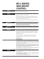
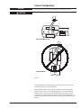
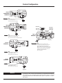
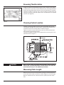
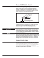
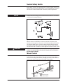
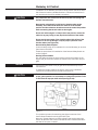
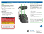
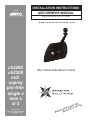
INSTALLATION INSTRUCTIONS MEMBER AND OWNERS MANUAL Part # 055001-687, Rev 2, 07/2013 www.seastarsolutions.com ch2200 ch2300 mt3 osprey pro-trim single s twin s sl-3 MANUFACTURED BY MARINE ACQUISITION INCORPORATED DBA SEASTAR SOLUTIONS U.S.A. MV-3 Series Side Mount Control ® ay, ay. w r yout our w t i o u d e try i o y re as Befo ple MV-3 SERIES SIDE MOUNT CONTROL NOTICE Installer: these instructions contain important safety information and must be forwarded to the boat owner. NOTICE Cable installation and connections must be made in accordance with the motor manufacturer’s instructions. To insure best performance, free operation of all linkages and the remote control is essential. Follow the manufacturer’s recommended procedures for adjustment and lubrication. All specifications and features are subject to change without notice. WARNING Before starting installation read these instructions and engine makers instructions thoroughly. Failure to follow either of these instructions or incorrect assembly can result in loss of control and cause property damage, injury, or death. WARNING DO NOT substitute parts from other manufacturers, they may cause a safety hazard for which SeaStar Solutions cannot accept responsibility. NOTICE SeaStar Solutions highly recommends the installation and usage of an engine shut off switch as a important emergency safety feature for boats. This switch should be connected by a cord to the boat driver. Should the driver be thrown from the helm position, the engine will automatically shut off. This shut off switch is not a standard part of the control you are using. It can, however, be obtained from most marine dealers and distributors. Introduction The SeaStar Solutions MV-3 Control is designed to provide convenient, one hand, single lever operation of shift and throttle for most popular outboards, sport jets, inboards equipped with hydraulic reverse gears and Berkeley or similar jet pumps. A safety feature of the MV-3 is a Neutral Locking Hand Lever. It can only be disengaged from Neutral by raising the lifter under the ball knob. The MV-3 accepts SeaStar Solutions 3300/33C Cables or 33C Xtreme cables. Some jet models use a 4300 Series Shift cable. A neutral safety switch is standard, except on MV-3 controls assembled for inboard ski boats and Berkeley Jet controls. NOTICE Page 2 of 16 The following information shows the procedures necessary to make a correct installation. General operation and adjustment information is provided, along with periodic maintenance information. A replacement part availability for the control is provided should the need for replacements become necessary. SeaStar Solutions Installation Instructions and Owner’s Manual Telephone: 610-495-7011 Control Configuration NOTICE CAUTION The MV-3 Control can only be mounted in a horizontal position. Do not remove hand lever to change position. Horizontal Mount Only Vertical Mount Figure 1. The next page is provided to make sure that you have the correctly configured control for your application. Operate MV-3 control hand lever to see how the shift and throttle levers move. If they move in the right direction, you do not have to change them. If control is not assembled for proper action of shift and throttle function required by engine or left hand configuration is required, reassemble control as shown in following instructions of this section. web: www.seastarsolutions.com SeaStar Solutions 640 North Lewis Road, Limerick, PA 19468 USA Page 3 of 16 Control Configuration Part # CH2900P& CH2910P Bow Right hand mount, cables forward without Neutral safety switch For use with inboard ski boats Part # CH2920P& CH2930P Cable Pivot Shift cable rod 6.35mm .25 Shift cable attaches at these holes Shift cable assembly Part # CH2950P Bow Right hand mount, cables aft with Standard neutral safety switch For use with inboards, outboards and I/O’s Throttle cable assembly Part # CH2940P Bow Right hand mount, cables aft with Immersion proof safety switch, warm-up limiter and heavy duty shift cable for Mercury Marine 175 horsepower jet drive. Cables must be installed to the CH2950P control as shown above when used with the Mercury 175 horsepower Sport Jet engine. Bow Right hand mount, Berkeley Jet Uses 43BC shift cable Neutral safety switch optional Part # CH2945P Bow Left hand mount, Berkeley Jet Uses 43BC shift cable Neutral safety switch optional Figure 2. NOTICE Page 4 of 16 To determine the correct control assembly for inboards with hydraulic transmissions, you must determine if the shift cable “pulls” or “pushes” to go into forward and if the throttle cable “pulls” or “pushes” to open the throttle. SeaStar Solutions Installation Instructions and Owner’s Manual Telephone: 610-495-7011 Repositioning Shift Arm Shift Arm Mercury (Long Stroke) Standard Cable Entry If the transmission shift function is different than the control shift arm, reposition the arm by removing hex head screw and rotate the shift arm 180 degrees. Pay attention to the 2-hole pattern on the shift arm for mounting pivot. See Figure 3. Brass Pivot Figure 3. CAUTION Neutral Safety Switch If the shift arm is repositioned, the neutral safety switch must also be repositioned or the switch will be damaged. (See Figure 4.) Control Connection and Recommended Clearance Switch terminals away from Shift Arm Figure 4. Figure 6. web: www.seastarsolutions.com SeaStar Solutions 640 North Lewis Road, Limerick, PA 19468 USA Page 5 of 16 Reversing Throttle Action Throttle Cable Connection Figure 5. All MV-3 controls are assembled to give a “PULL” action on the cable. If cable action is incorrect, reverse throttle arm by removing Hex Head Screw and large flat washer. Remove arm and reassemble in opposite position as shown in Figure 5. Also, reverse position of dwell block and spring by removing screw, flat washer and nut. Reassemble in opposite position (see Figure 5). Choosing Control Location Choose a mounting location for the control head which will provide comfortable operation of the hand lever, unobstructed movement of mechanism arms and a clear path for cables to engine. Figure 6 shows the control dimensions and the recommended clearance behind the mounting surface. Using the template provided, cut the appropriate mounting hole in the panel as shown in Figure 7. Figure 7. CAUTION When control comes with cutoff switch installed, panel thickness must be .50" (12.7mm) maximum. If cutoff switch is not used, the panel thickness may be .75" (19.05mm) maximum. Measuring Cable Length Measure from the control head position along an unobstructed path to the shift and throttle connections. Cable lengths are overall length. When a measurement is in feet and inches, specify the next whole foot. Page 6 of 16 SeaStar Solutions Installation Instructions and Owner’s Manual Telephone: 610-495-7011 Installation of Cables A. BEND RADIUS. When routing the control cables, select a path with the minimum number of bends, making the bends as large as possible. Sharp or frequent bends will result in difficult throttle or shift control, loss of motion, and premature cable wear. DO NOT MAKE BENDS OF LESS THAN THE RECOMMENDED MINIMUM BEND RADIUS AS NOTED BELOW. Cable Type Standard 3300/33C Xtreme 3300 Cable Minimum Bend Radius 8" 4" For best performance, SeaStar Solutions recommends using Xtreme cables with this control. B. SUPPORTING THE CABLE. Do not tie or clamp the cable within 36 inches of the control. When supporting the cable beyond 36 inches of the control, cables should be loosely clamped or tied for support at regular intervals. CAUTION Cables must not be bundled together with electrical wiring. Cables must not rest on sharp edges which can cause chafing. C. CABLE ROUTING. Cables shall not be installed in areas of excess heat such as on, or close to, exhaust manifolds where temperatures may exceed 212°F (100°C). web: www.seastarsolutions.com SeaStar Solutions 640 North Lewis Road, Limerick, PA 19468 USA Page 7 of 16 Connect Shift Cable to Control Insert shift cable through opening in hanger assembly in line with shift arm pivot attachment hole and lock cable in hanger slot. Screw pivot onto cable rod, allowing threads to protrude through pivot 1/8” for standard travel or 1/4” for long travel. (See Figure 8.) Lubricate pivot with grease, then insert into required hole in shift arm Fasten with cotter pin. Tighten cable nut against pivot. Brass pivot Cable jam nut Cable rod .125" (3.17 mm) Standard travel .25" (6.35 mm) Long travel Figure 8. To obtain standard (2 3/4” ) cable shift travel at engine, use shift arm on control at short pivot hole location as shown in Figure 3. For Mercury, long (3 inch) cable shift travel at engine is necessary. Assemble shift arm to control using longest pivot hole location. CAUTION NOTICE The pivot must be in the hole nearest to cable entry end of the control. Using the hole in the shift arm further most away from the cable mounting support will produce unequal shift travel between “neutral to forward” and “neutral to reverse”, resulting in improper shift action. (See Figure 3.) The control shift lever and the transmission shift lever must coincide at the forward, neutral and reverse positions. Different makes of transmissions may require different amounts of shift travel. For this reason, the control shift lever is provided with two (2) positions for attaching the shift cable: one for the standard travel and one for the longest travel. (See Figure 3.) Connect Throttle Cable With opening in swivel bracket nearest to the cable entry end of the control, insert throttle cable through opening in swivel bracket and secure cable hub in bracket slot. Screw pivot onto cable rod and allow cable rod threads to protrude through pivot 1/8 inch (3.17mm). Lubricate pivot with grease, then insert into hole in throttle arm. Fasten with cotter pin. Tighten cable nut against pivot. Page 8 of 16 SeaStar Solutions Installation Instructions and Owner’s Manual Telephone: 610-495-7011 Neutral Safety Switch Some MV-3 controls are equipped with a neutral safety switch. For controls without a neutral safety switch, it can be added and is sold as a service item in both standard and immersion proof configurations. NOTICE SeaStar Solutions strongly recommends that the switch be connected to assure safe boating operation. NC Figure 9. With the Control in NEUTRAL, connect one wire of the tester to the common terminal and one wire to the “NC” (Normally Closed) Terminal. The test light MUST light. Connect the Neutral Safety Switch between the ignition switch (start lead) and the starter solenoid. (See Figure 9.) Use terminals with insulators to insure against an electrical short circuit. CAUTION Check to make sure that there is electrical continuity only when the control is in neutral. When the control is in gear, there must not be any electrical continuity. Mount Control Cable Path. Run the cables, which are connected to the control, back to the throttle and shift location of the engine and drive. The cables should run as straight as possible, avoiding any sharp bends. Make no bends in the cable of less than 8 inch (203.2 mm) radius. 24.0" (609 mm) Minimum Swivel Bracket Loose tie Allow 4.0" (101 mm) for cable movement Figure 10. web: www.seastarsolutions.com SeaStar Solutions 640 North Lewis Road, Limerick, PA 19468 USA Page 9 of 16 Installation of Control. Shift control into forward to move shift arm out of the way. This allows the control to be inserted into the cut out. When satisfied with the position of the control, fasten housing to mounting surface with three (3) #10 thread cutting screws. One screw is 1.50 inches (38.1mm) long and it is used in the single hole (see Figure 6). CAUTION Do not use cable hangers or clamps which may crush or stress the cables in any way. Doing so may impair the function of the cables. Do not restrict movement of the throttle cable within 2 feet of the control. (See Figure 10.) To do so may damage or impair proper operation of the throttle cables. Connecting Cables to Engine Connect the shift and throttle cables to the throttle and shift levers at the engine following the instructions provided with the appropriate connection kit or with the engine. Shift Cable Connection and Adjustment The shift cable must be connected so that the “FORWARD”, “NEUTRAL” and “REVERSE” positions of the control shift lever will coincide with the forward, neutral and reverse positions of the transmission lever. Readjust the cable terminals until the correct function of the shift lever is achieved. Proper adjustment of the shift cable will result in a much better operating control. NOTICE CAUTION Having the control lever and the transmission lever both in forward gear will help with your final shift cable adjustments. Over jamming the transmission stop on either end of the shift travel may: 1. Cause excessive wear of the drive and shift gear. 2. Result in a “heavy” feel of the hand lever and/or 3. Over stress and damage the cable. Throttle Cable Connection and Adjustment CAUTION The throttle cable must be disconnected from the motor before making motor idle adjustments. Adjustment of the motor idle while the throttle cable is still connected to the motor may cause a jamming action against the idle stop. As a result, the control may not function properly and damage to the control, the cable and/or the motor could result. STEP 1. Adjust the motor to a smooth idle as recommended by the motor manufacturer. This must be done BEFORE connecting the control throttle cable to the carburetor. STEP 2. Place the hand lever of the control into the forward detent position. STEP 3. Place the carburetor arm lightly against the idle stop. STEP 4. Adjust the throttle cable terminal (at the motor end) to line up with the hole (or pin) on the carburetor arm, then connect the terminal to the arm. Proper adjustment of the throttle cables will assure having long life from this control. When the throttle cable is correctly adjusted, the motor speed will remain at idle while the control is shifted and will increase only when the hand lever is moved beyond the shift detent. Page 10 of 16 SeaStar Solutions Installation Instructions and Owner’s Manual Telephone: 610-495-7011 CAUTION Unless the afore mentioned procedures, steps 1 through 4, are followed, engine R.P.M. will raise excessively during the shift cycle. For this reason, there is a compression spring-type throttle dwell build into the cable anchor assembly which allows throttle cable action to remain stationary during the shift cycle. (See Figure 5.) As a result, the hand lever must be in the forward detent position and the carburetor throttle arm must be at idle position while connecting the throttle cable to the engine. Operation and Adjustment The MV-3 Control is equipped with a throttle “warm-up” feature. Operation: Shift and Throttle. For starting or warm-up, place the control in Neutral Detent position, then grasp button beside the hand lever hub and pull out (approximately .20”) to disengage shift. Lift collar under hand lever knob and move hand lever ahead of the forward shift detent to advance throttle for neutral warm-up. When warm-up is completed, return hand lever to neutral detent. The “warmup” button is spring loaded and it will snap back in place when hand lever is brought back to neutral. Push in on the button to make sure it is fully in. The control is ready for shift and throttle operation. CAUTION Do not force shift when the motor is not running. To do so may damage the control, the cables and/or the motor, especially outboards. WARNING Do not shift too quickly from forward to reverse. Stay in the neutral or idle position until the boat has lost most of its headway before completing the shift to reverse. Some models are designed to limit the throttle R.P.M. web: www.seastarsolutions.com SeaStar Solutions 640 North Lewis Road, Limerick, PA 19468 USA Page 11 of 16 Berkeley Jet Control Installation of the Berkeley Jet Control closely follows that of the other MV-3 Controls made by SeaStar Solutions. Follow the instructions in this booklet plus these few added instructions: CAUTION Very Important! This control can be used only with non-spring link throttle connection kits. Because the spring dwell is built into the throttle cable anchor assembly, the control head hand lever must be in the forward position and the carburetor throttle arm must be at the idle position while connecting the throttle cable to the engine. Do not use cable hangers or clamps which may crush or stress the cables in any way. Doing so may impair the function of the cables. Do not restrict movement of the throttle cable within 2 feet of the control. To do so may damage or impair proper operation of the throttle cables (see Figure 10). Neutral Safety Switch Option. A neutral safety switch kit is available for use with Berkeley jet versions (Part Number 311453). Follow the procedures for installation of the Neutral Safety Switch as outlined page 9. Routing Control Cables. Run the cables through the panel cutout back to the location of the engine and jet drive, then attach the cables to the carburetor and jet gate. NOTICE CAUTION Connect the shift cable to the jet gate as recommended by the jet manufacturer. To install the throttle cable to the engine, refer to the installation instructions provided with the throttle connection kit. The shift and throttle arms have been offset 15 degrees to assure proper gate operation. Do not attempt to change this position. To do so will result in improper shift action (see Figure 11). Figure 11. This provides a means for absorbing the slight movement of the Control Head Throttle Arm during the shift cycle. When the Throttle Cable is correctly adjusted, the engine speed will remain at idle while the Control is shifted and will increase ONLY after the Gate is full open or closed. Page 12 of 16 SeaStar Solutions Installation Instructions and Owner’s Manual Telephone: 610-495-7011 Control Installation Completion. Place the Hand Lever in the FORWARD position so that, as a result, the Shift Arm and Throttle Arm will take the smallest amount of space to feed the Hanger Bracket through the panel cutout. Fastening recommendations are as follows: For Normal Mounting: 2 each, Oval Head #10 x 1-1/4” long Self-Tapping Screws. 1 each, #10 x 1-1/2” long Self Tapping Screws. Engine Cable Connections: Connect the Shift and Throttle Cables to the Shift and Throttle levers at the engine, following the instructions provided with the appropriate Connection Kit or with the engine. Final Adjustments. Operate the Hand Lever several times. The Jet Gate should be FULLY OPEN or FULLY CLOSED before the carburetor arm leaves the Idle Stop. Adjust the Cable Terminal at the carburetor, if necessary, to obtain this result. NOTICE When the throttle cable is correctly adjusted, the engine speed will remain at idle while the control is shifted and will increase only after the gate is fully open or fully closed. MV-3 For Sports Boats (Inboards and Outboards) Parts Available 3 4 INBOARD & OUTBOARDS CONTROL ITEM DESCRIPTION 1 2 3 4 5 Hand Lever Assembly with Knob Neutral Safety Switch-Standard N.S. Switch-Immersion Proof Hand Lever Ball Kit Hub Insert Mounting Hardware (not shown) web: www.seastarsolutions.com CONTROL MODEL NUMBER (SEE PAGE 4 FIGURE 2) ITEM PART NUMBER All Models CH2920P & CH2930P CH2950P All Models All Models All Models except CH2950P CH2950P 311354 300928 051801-031 CA68287P 7173619 311336 311510 SeaStar Solutions 640 North Lewis Road, Limerick, PA 19468 USA Page 13 of 16 MV-3 For Berkeley Jets 2 Parts Available 3 ITEM 1 2 3 4 5 Page 14 of 16 DESCRIPTION CONTROL PART NUMBER (SEE PAGE 4, FIGURE 2) ITEM PART NUMBER Hand Lever Assembly with Knob Hand Lever Ball Kit Hub Insert Mounting Hardware (not shown) Neutral Safety for Berkeley CH2940P and CH2945P CH2940P and CH2945P CH2940P and CH2945P CH2940P and CH2945P CH2940P and CH2945P 311354 CA68287P 7173619 311411 311453 SeaStar Solutions Installation Instructions and Owner’s Manual Telephone: 610-495-7011 Maintenance Notes 1. After a few hours of operation and at frequent intervals thereafter, check all fasteners and the complete control system for security and integrity. DANGER Loosening or loss of one or more fasteners may cause failure of the control system and could cause property damage, injury, or death. 2. Keep all moving parts free from build-up of salt and other foreign material. This will affect their operation and create control problems. 3. Inspect periodically for corrosion. Any parts affected by corrosion must be replaced. Any replacement hardware must be as originally supplied (i.e. similar material and locking features). 4. Inspect control cables periodically for cracks and other damage. If any is found the cable must be replaced. 5. If cable is stiff in operation, it is unsafe to use and must be replaced immediately. DANGER NOTICE web: www.seastarsolutions.com DO NOT cover cracks with tape or other sealants. This will create a hazard in which the cable can fail suddenly without warning, resulting in property damage, injury, or death. Boat builder and boat dealer, please supply these Installation Instructions and Owner’s Manual with the delivery of boat. Boat owner keep these instructions with your boat for future reference. Boat owner consult with your boat builder, boat dealer, or SeaStar Solutions if you have any questions regarding these instructions. SeaStar Solutions 640 North Lewis Road, Limerick, PA 19468 USA Page 15 of 16 © 1995 MARINE ACQUISITION (US) INC. PART # 055001-687 07-2013 Rev. 2