1
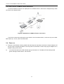
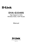
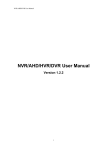
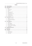
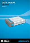
s C2-010/C2-010-I ADSL2+ Router User’s Manual Rev: 1.3 2005/1210 No part of this publication may be reproduced in any form by any means without the prior written permission. Other trademarks or brand names mentioned herein are trademarks or registered trademarks of their respective companies. This manual currently suits for C2-010/C2-010-I. C2-010 / C2-010-I ADSL2+ Router User’s Guide Contents 1.1 Device Introduction....................................................................................................................... 1-1 1.2 Features........................................................................................................................................ 1-1 2.1 Packing List .................................................................................................................................. 2-1 2.2 Interfaces Introduction .................................................................................................................. 2-1 2.2.1 Front Panel................................................................................................................................ 2-1 2.2.2 Rear Panel ................................................................................................................................ 2-2 2.3 Cable Connections ....................................................................................................................... 2-2 2.3.1 Connecting the ADSL Line........................................................................................................ 2-2 2.3.2 Connecting the ADSL2+ Router to the Ethernet LAN............................................................... 2-2 2.3.3 Computer to ADSL2+ Router Connection................................................................................. 2-3 2.3.4 Hub or Switch to ADSL2+ Router Connection .......................................................................... 2-4 2.4 Power on....................................................................................................................................... 2-4 3.1 Set up TCP/IP on Your PC .......................................................................................................... 3-1 3.2 Set up Proxy Service .................................................................................................................... 3-1 3.3 Configure IP Settings on Your PC ................................................................................................ 3-1 3.4 First Time Log on .......................................................................................................................... 3-2 4.1 Summary ...................................................................................................................................... 4-1 4.2 Configuring the WAN Connection................................................................................................. 4-2 4.2.1 Configuring a Bridged Connection for the WAN ....................................................................... 4-4 4.2.2 Static IP Address for Connection WAN ..................................................................................... 4-5 4.2.3 Dynamic IP Address Connection for WAN................................................................................ 4-8 4.2.4 PPPoE and PPPoA Connection for WAN ............................................................................... 4-10 4.3 DHCP Configuration ................................................................................................................... 4-12 4.3.1 DHCP Server Settings for the LAN ......................................................................................... 4-12 4.3.2 Use the ADSL2+ Router for DHCP ......................................................................................... 4-12 4.3.3 Disabling the DHCP Server .................................................................................................... 4-13 4.4 DNS Server Setting .................................................................................................................... 4-13 4.5 Configuring the LAN Connection ................................................................................................ 4-13 5.1 UPnP Configuration ...................................................................................................................... 5-2 5.2 Virtual Server Configuration ......................................................................................................... 5-3 5.3 SNMP Configuration ..................................................................................................................... 5-4 5.4 Outbound IP Filter Configuration .................................................................................................. 5-5 5.5 Inbound IP Filter Configuration..................................................................................................... 5-6 5.6 Firewall ......................................................................................................................................... 5-8 5.7 DMZ .............................................................................................................................................. 5-9 5.8 RIP.............................................................................................................................................. 5-10 5.9 PPP............................................................................................................................................. 5-11 5.10 ADSL .......................................................................................................................................... 5-12 5.11 ATM VCC.................................................................................................................................... 5-13 6.1 Administrator’s Settings................................................................................................................ 6-1 6.2 Configure System Time ................................................................................................................ 6-2 I C2-010 / C2-010-I ADSL2+ Router User’s Guide 6.3 Save ADSL2+ Router Configuration Settings............................................................................... 6-2 6.4 Restore Factory Default Settings.................................................................................................. 6-3 6.5 Save Configuration File to PC ...................................................................................................... 6-3 6.6 Load Saved Configuration Files ................................................................................................... 6-3 6.7 Firmware Update .......................................................................................................................... 6-3 6.8 Test ............................................................................................................................................... 6-4 7.1 Device Info.................................................................................................................................... 7-1 7.2 Log................................................................................................................................................ 7-1 7.3 Traffic Statistics............................................................................................................................. 7-2 7.4 ADSL Status ................................................................................................................................. 7-3 8.1 Technical Specifications................................................................................................................ 8-1 II C2-010 / C2-010-I ADSL2+ Router User’s Guide 1. Overview The ADSL2+ Router provides integrated voice and data services over ADSL “Asymmetrical Digital Subscriber Loop” WAN (Wide Area Network) connection. 1.1 Device Introduction The ADSL2+ Router is designed to provide a simple and cost-effective ADSL Internet connection for individual computers through the Ethernet ports, or use it to bridge your Ethernet LAN to the Internet. The ADSL2+ Router combines the benefits of high-speed ADSL technology and LAN IP management in one compact and convenient package. ADSL technology enables many interactive multi-media applications such as video conferencing and collaborative computing. The ADSL2+ Router is easy to install and use. The ADSL2+ Router connects to computers or an Ethernet LAN via a standard Ethernet interface. The ADSL connection is made using ordinary twisted-pair telephone line with standard connectors. Multiple PCs can be networked and connected to the Internet using a single Wide Area Network (WAN) interface and single global IP address. 1.2 Features Data rates up to 26 Mbps downstream Bridging and routing capabilities PPP and tunneling features Firewall with Dynamic Host Configuration Protocol (DHCP), Network Address Translation (NAT), Pointto-Point Tunneling Protocol (PPTP), and Layer 2 Tunneling Protocol (L2TP). Supports ADSL, ADSL2, ADSL2+ DSL Forum TR-048-compliant DSL CPE auto-configuration UPnP for seamless network interconnectivity Comprehensive networking protocol support includes DHCP Friendly web-based graphical user interface for configuration and management Supports up to eight simultaneous virtual connections for a single ADSL account Supports T1.413 issue 2, G.dmt and G.lite standards Auto-handshake and rate adaptation for different ADSL flavors Widest range of DSLAM interoperability Supports bridged Ethernet over ATM (RFC 2684) Upgradeable firmware through web 1-1 C2-010 / C2-010-I ADSL2+ Router User’s Guide 2. Installation Planning Before installing the ADSL2+ Router, you should gather information and equipment needed to install the device, then Install the hardware as instructed, connect the cables to the device and power on the ADSL2+ Router. Prior to accessing the web-based software built into the ADSL2+ Router, you should check the IP settings on your computer and change them if necessary. 2.1 Packing List Please check the package contents by comparing them with the following list: One ADSL2+ Router One telephone lines One straight-through Ethernet Cable One Power Adapter 2.2 Interfaces Introduction 2.2.1 Front Panel Figure 2–1 Front Panel Power Steady green light indicates the unit is powered on. When the device is powered off this remains dark. Status Lights steady green during power on self-test (POST). Once the connection status has been settled, the light will blink green. If the indicator lights steady green after the POST, the system has failed and the device should be rebooted. ADSL: Link/Act Steady green light indicates a valid ADSL connection. This will light after the ADSL negotiation process has been settled. A blinking green light indicates activity on the WAN (ADSL) interface. LAN: Link/Act A solid green light indicates a valid link on startup. This light blinks when there is activity currently passing through the Ethernet port. 2-1 C2-010 / C2-010-I ADSL2+ Router User’s Guide 2.2.2 Rear Panel ADSL port − Connect to the ADSL line Ethernet port − to your PC’s Ethernet port Power input − Connect power adapter here Factory Reset Button Figure 2-2 Rear Panel 2.3 Cable Connections After verifying proper environmental conditions such as temperature, humidity and power supply, users may start the cable connections as following. 2.3.1 Connecting the ADSL Line Use the ADSL cable included with the ADSL2+ Router to connect it to a telephone wall socket or receptacle. Plug one end of the cable into the ADSL port (RJ-11 receptacle) on the rear panel of the ADSL2+ Router and insert the other end into the RJ-11 wall socket. If you are using a low pass filter device, follow the instructions included with the device or given to you by your service provider. The ADSL connection represents the WAN interface, the connection to the Internet. It is the physical link to the service provider’s network backbone and ultimately to the Internet. 2.3.2 Connecting the ADSL2+ Router to the Ethernet LAN The ADSL2+ Router may be connected to a single computer or Ethernet device through the 10BASE-TX Ethernet port on the rear panel. Any connection to an Ethernet concentrating device such as a switch or hub must operate at a speed of 10/100 Mbps only. When connecting the ADSL2+ Router to any Ethernet device that is capable of operating at speeds higher than 10Mbps, be sure that the device has auto-negotiation (NWay) enabled for the connecting port. Use standard twisted-pair cable with RJ-45 connectors. The RJ-45 port on the ADSL2+ Router is a crossed port (MDI-X). Follow standard Ethernet guidelines when deciding what type of cable to use to make this connection. When connecting the ADSL2+ Router directly to a PC or server use a normal straightthrough cable. You should use a crossed cable when connecting the ADSL2+ Router to a normal (MDI-X) port on a switch or hub. Use a normal straight-through cable when connecting it to an uplink (MDI-II) port on a hub or switch. The rules governing Ethernet cable lengths apply to the LAN to ADSL2+ Router connection. Be sure that the cable connecting the LAN to the ADSL2+ Router does not exceed 100 meters. 2-2 ADSL2+ Router User’s Guide 2.3.3 Computer to ADSL2+ Router Connection Cat 5 Ethernet Cable Figure 2-3 Computer to ADSL2+ Router Connection You can connect the ADSL2+ Router directly to a 10/100BASE-TX Ethernet adapter card (NIC) installed on a PC using the Ethernet cable provided as shown in this diagram. 2-3 C2-010 / C2-010-I ADSL2+ Router User’s Guide 2.3.4 Hub or Switch to ADSL2+ Router Connection Connect the ADSL2+ Router to an uplink port on an Ethernet hub or switch with a straight-through cable as shown in the diagram below: Figure2-5 Hub/Switch to ADSL2+ Router Connection If you wish to reserve the uplink port on the switch or hub for another device, connect to any on the other MDI-X ports (1x, 2x, etc.) with a crossed cable. 2.4 Power on 1) To power on the ADSL2+ Router, please follow the steps as instructed: Insert the AC Power Adapter cord into the power receptacle located on the rear panel of the ADSL2+ Router and plug the adapter into a suitable nearby power source. 2) You should see the Power LED indicator light up and remain lit. The Status LED should light solid green and begin to blink after a few seconds. 2-4 C2-010 / C2-010-I ADSL2+ Router User’s Guide 3. Before Configuring ADSL2+ Router The factory default settings of ADSL2+ Router optimized all functions so as to enable it to operate on most network conditions. Usually, for the users with simple network topology, the default settings can meet the basic requirements and don’t need to change. In order to access the web-based software built into the ADSL2+ Router, you should check the IP settings on your computer and change them if necessary to access web-based manager to configure the device. 3.1 Set up TCP/IP on Your PC In order to configure your system to receive IP settings from the ADSL2+ Router it must first have the TCP/IP protocol installed. If you have an Ethernet port on your computer, it probably already has TCP/IP protocol installed. Please follow the instructions to check your IP protocol: 1) In Windows task bar, click the Start button, point to Settings>Network and Dial-up Connection> and click on Local Connection. 2) Click on Properties> Select Internet Protocol (TCP/IP) and then Click Properties. 3) Click on the button labeled use the following IP address, Then you can set the IP address and Subnet mask, for example, 192.168.1.100 and 255.255.255.0. Note: If Internet Protocol (TCP/IP) does not display as an installed component, you must install it. 3.2 Set up Proxy Service In Windows Internet Explorer, you can check if a proxy server is enabled using the following procedure: 1) Click on the START button, go to Settings and choose Control Panel. 2) In the Control Panel window, double-click on the Internet Options icon 3) Click the Connections tab and click on the LAN Settings button. 4) Verify that the “Use proxy server” option is NOT checked. If it is checked, click in the checked box to deselect the option and click OK. 3.3 Configure IP Settings on Your PC To use the web-based management software, launch your web browser software and use the LAN IP address of the ADSL2+ Router to access the management software. The default LAN IP address of the ADSL2+ Router is used in the Address bar of your web browser window. Type in http:// followed by the default IP address, 192.168.1.1 in the address bar of the browser. The URL in the address bar should read: http://192.168.1.1 3-1 C2-010 / C2-010-I ADSL2+ Router User’s Guide 3.4 First Time Log on After inputting the forgoing IP address on URL address bar, a new window appears prompting you for a user name and password needed to gain access the web configuration manager. Figure 3-1. Log On Interface Use the default system user name: admin and password: admin for first time set up. You can change the password once you have established the ADSL connection. The user name and password allows any computer on the same subnet as the ADSL2+ Router to access the web configuration manger. This password can also be used to Telnet to the device through the Ethernet or the Internet interfaces. 3-2 C2-010 / C2-010-I ADSL2+ Router User’s Guide 4. Web-based Management 4.1 Summary When you successfully login the Basic directory will display the ADSL2+ Router’s current connection status − both for the WAN (Internet) and LAN (your home network) connections, as shown below. You can begin the process of configuring your ADSL modem/ADSL2+ Router by clicking on the Advanced button in the upper left-hand corner of the first Web page displayed. This will open the Wizard page, as shown below. Click on a button to view the menus available in that directory Figure 4-1. Web Manager – Basic Page Figure 4-2. Web Manager – Wizard Page 4-1 C2-010 / C2-010-I ADSL2+ Router User’s Guide Each tab displays menu buttons located in the left hand panel of the web interface. The table below lists the menus for each directory in the web manager. Directory Configuration and Read-only Menus Home Click the Home tab to access the Summary, WAN, DHCP, DNS, and LAN Configuration menus. Advanced Click the Advanced tab to access the Virtual Server, Application, Filter, Firewall, NAT, DDNS, and RIP menus. Tools Click the Tools tab to access the Administrator Settings (used to set the system user name and password), System Time Configuration, System Settings (load and save configuration files) and Firmware menus. Status Click the Status tab to view the Log, Diagnostic, and Statistics information windows. Help The Help menu presents links to pages that explain various functions and services provided by the ADSL2+ Router. Table 4-2 Options of Web-based page 4.2 Configuring the WAN Connection To configure the ADSL2+ Router’s basic configuration settings, you can access the menus used to configure WAN, DHCP, DNS and LAN settings from the Home directory. To access the WAN Settings menu, click on the WAN link button on the upper left-hand side of the first window that appears when you successfully access the web manager. The WAN Settings menu is also used to configure the ADSL2+ Router for multiple virtual connections. The next section contains information on how to configure the ADSL2+ Router for Multiple PVCs. Please note that most users will require only single PVC. Select the connection type used for your account. The menu will display settings that are appropriate for the connection type you select. Follow the instruction below according to the type of connection you select in the WAN Settings menu. Your Internet Service Provider (ISP) should provide the information you need to select the proper connection type. 4-2 ADSL2+ Router User’s Guide Figure 4-3 WAN Current Settings Menu Select the connection type used for your account. The menu will display settings that are appropriate for the connection type you select. Follow the instruction below according to the type of connection you select in the WAN Settings menu. Your Internet Service Provider (ISP) should provide the information you need to select the proper connection type. To configure the Router’s basic configuration settings without running the Setup Wizard, you can access the menus used to configure WAN, LAN, DHCP and DNS settings directly from the Home directory. To access the WAN Settings menu, click on the WAN link button on the left side of the first window that appears when you successfully access the web manager. The WAN Settings menu is also used to configure the Router for multiple virtual connections (Multiple PVCs). Note: you can configure up to seven different connections on your ADSL2+ Router ADSL Modem/ADSL2+ Router by assigning a number to each configuration using the drop-down menu corresponding to the ATM Interface heading. This could be useful if you have several ISPs and need to configure the ADSL2+ Router differently for each. Most users will require only single PVC, however. 4-3 C2-010 / C2-010-I ADSL2+ Router User’s Guide 4.2.1 Configuring a Bridged Connection for the WAN A bridged connection between your ISP and your LAN (the computers in your house or office) is the simplest type of connection possible. The ADSL2+ Router will simply convert the incoming and outgoing packets to the correct format for each side of the connection (Ethernet for the LAN, ATM for the WAN). For a bridged connection it will be necessary for most users to install additional software (supplied by your ISP) on any computer that will use the ADSL2+ Router for Internet access. The additional software is used for the purpose of identifying and verifying your account, and then granting Internet access to the computer requesting the connection (that is, the software supplied by your ISP will handle giving your Username and Password to the computer at your ISP that will then connect you to the Internet). The connection software requires the user to enter the User Name and Password for the ISP account. This information is stored on the computer on the LAN, not in the ADSL2+ Router for a bridged connection. Follow the instructions below to configure a Bridged connection for the WAN interface. Figure 4-4 WAN Settings Menu – Bridge Mode Note: Please note that the menu shown above will change depending on which WAN Type and Connection Type you select. To configure a Bridged mode connection, perform the steps listed below. Some of the settings do not need to be changed the first time the device is set up, but can be changed later if you choose. See the table below for a description of all the settings available in this menu. 1. Choose the Bridge Mode option from the WAN Settings pull-down menu. 2. Under the ATM Interface settings at the top of the menu (including VPI, VCI, and Virtual Circuit) should not be changed unless you have been instructed to change them. However, if you are instructed to change the VPI or VCI values, type in the values assigned for your account. Leave the ATM Interface and Virtual Circuit setting at the default (Pcv0 and Enabled) values for now. This can be used later if you are configuring multiple virtual circuits for your ADSL service. 3. Under the Bridge Mode heading, choose the Connection Type from the pull-down menu. This defines both the connection type and encapsulation method used for your ADSL service. The available options are 1483 Bridged IP LLC and 1483 Bridged IP VC-Mux. If have not been provided specific information for the Connection Type setting, leave the default setting. 4-4 ADSL2+ Router User’s Guide 4. When you are satisfied that all the WAN settings are configured correctly, click on the Apply button. Note: Some accounts use PPP connection software for their Internet service connection. If you have been given a CD with PPP connection software, install this now as instructed by your service provider. After the ADSL2+ Router has rebooted it will negotiate the ADSL connection. Use the connection software to log on to the ISP network and access the Internet. 4.2.2 Static IP Address for Connection WAN When the Router is configured to use Static IP Address assignment for the WAN connection, you must manually assign a global IP Address, Subnet Mask and Gateway IP Address used for the WAN connection. Most users will also need to configure DNS server IP settings in the DNS Settings configuration menu (see below). Follow the instruction below to configure the Router to use Static IP Address assignment for the WAN connection. To configure a Static IP Address connection, perform the steps listed below. Some of the settings do not need to be changed the first time the device is set up, but can be changed later if you choose. See the table below for a description of all the settings available in this menu. Figure 4-5 WAN Settings Menu – Static IP Address To configure a Static IP type connection for the WAN, follow these stpes: 1. Choose the Static IP Address option from the WAN Settings pull-down menu. 2. Under the ATM Interface settings at the top of the menu (including VPI, VCI, and Virtual Circuit) should not be changed unless you have been instructed to change them. However, if you are instructed to change the VPI or VCI values, type in the values assigned for your account. Leave the ATM Interface and Virtual Circuit setting at the default (Pcv0 and Enabled) values for now. This can be used later if you are configuring multiple virtual circuits for your ADSL service. 4-5 C2-010 / C2-010-I ADSL2+ Router User’s Guide 3. Under the Static IP heading, choose the Connection Type from the pull-down menu. This defines both the connection type and encapsulation method used for your ADSL service. The available options are Bridged IP LLC, Bridged IP VC-MUX, Routed IP LLC, Routed IP VC-MUX or IPoA.. If have not been provided specific information for the Connection Type setting, leave the default setting. 4. Change the IP Address, Subnet Mask, Gateway Address and (if available) Secondary DNS Server IP address as instructed by your ISP. These are the global IP settings for the WAN interface. This is the “visible” IP address of your account. Your ISP should have provided these IP settings to you. For IPoA (Classic IP over ATM) connections you may need to type in an additional IP address for a ARP Server Address. If you are using an IPoA connection, ask your ISP if it is necessary to use an ARP (Address Resolution Protocol) server. 5. Leave the MTU value at the default setting (default = 1400) unless you have specific reasons to change this (see table below). 6. Most users will not need to change ATM settings. If this is the first time you are setting up the ADSL connection it is recommended that you leave the Service Category settings at the default values until you have established the connection. See the table on page . שגיאה! הסימניה אינה מוגדרתfor a description of the parameters available for ATM traffic shaping. 7. When you are satisfied that all the WAN settings are configured correctly, click on the Apply button. 8. The new settings must be saved and the Router must be restarted for the settings to go into effect. To Save & Reboot the Router, click on the Tools directory tab and then click the Save & Reboot menu button. In the Save and Reboot menu, click the Reboot button under Force the DSL-300T to system restart. The Router will save the new settings and restart. Upon restarting the Router will automatically establish the WAN connection. Additional settings for Static IP Address connections: Static IP Address Parameters Description Connection Type This specifies the connection type and the encapsulation method used for your Static IP Address connection. The options available are Bridged IP LLC, Bridged IP VC-MUX, Routed IP LLC, Routed IP VC-MUX or IPoA. IP Address This is the permanent global IP address for your account. This is the address that is visible outside your private network. Get this from your ISP. Subnet Mask This is the Subnet mask for the WAN interface. Get this from your ISP. Gateway Address This is the IP address of your ISP’s Gateway router. It provides the connection to the Router for IP routed traffic that is outside your ISP’s network. That is, this will be the primary connection from the Router to most of the Internet. Get this IP address from your ISP. Primary DNS Address This is the IP address of the first choice for Domain Name Service (DNS) used to match the named URL web address used by most browsers with the actual global IP address used for a web server. Usually this will be a server owned by the ISP. Get this IP address from your ISP. Secondary DNS Address This is the second choice for a DNS server. Get this IP address from your ISP. Default Route Enabled/Disabled − this sets the router as the default route between the PCs on your LAN and the WAN (Internet). This should normally be enabled. 4-6 ADSL2+ Router User’s Guide Route NAT Enabled/Disabled − this enables or disables NAT (Network Address Translation) on the router. This should normally be enabled. IGMP Enabled/Disabled − this enables or disables IGMP (Internet Group Management Protocol) on the router. This should normally be enabled. 4-7 C2-010 / C2-010-I ADSL2+ Router User’s Guide 4.2.3 Dynamic IP Address Connection for WAN A Dynamic IP Address connection configures the Router to automatically obtain its global IP address from a DHCP server on the ISP’s network. The service provider assigns a global IP address from a pool of addresses available to the service provider. Typically the IP address assigned has a long lease time, so it will likely be the same address each time the Router requests an IP address. To configure a Dynamic IP Address connection, perform the steps listed below. Some of the settings do not need to be changed the first time the device is set up, but can be changed later if you choose. See the table below for a description of all the settings available in this menu. Figure 4-6 WAN Settings Menu – Dynamic IP Address 1. Under the ATM Interface settings at the top of the menu (including VPI, VCI, and Virtual Circuit) should not be changed unless you have been instructed to change them. However, if you are instructed to change the VPI or VCI values, type in the values assigned for your account. Leave the ATM Interface and Virtual Circuit setting at the default (Pcv0 and Enabled) values for now. This can be used later if you are configuring multiple virtual circuits for your ADSL service. 2. Under the Dynamic IP heading, choose the Connection Type from the pull-down menu. This defines both the connection type and encapsulation method used for your ADSL service. The available options are 1483 Bridged IP LLC and 1483 Bridged IP VC-Mux. If have not been provided specific information for the Connection Type setting, leave the default setting. 3. Some ISPs record the unique MAC address of your computer’s Ethernet adapter when you first access their network. This can prevent the Router (which has a different MAC address) from being allowed access to the ISPs network (and the Internet). To clone the MAC address of your computer’s Ethernet adapter, type in the MAC address in the Cloned MAC Address field and click the Clone MAC Address button. 4. Leave the MTU value at the default setting (default = 1400) unless you have specific reasons to change this (see table below). 4-8 ADSL2+ Router User’s Guide 5. NAT should remain enabled. If you disable NAT, you not be able to use more than one computer for Internet connections. NAT is enabled and disabled system-wide, therefore if you are using multiple virtual connections, NAT will disabled on all connections. 6. The Firewall should remain enabled for most users. If you choose to disable this you will not be able to use the features configured in the Firewall and Filters menus located in the Advanced directory. See the next chapter for more details on these menus. 7. Most users will not need to change ATM settings. If this is the first time you are setting up the ADSL connection it is recommended that you leave the Service Category settings at the default values until you have established the connection. See the table on page . שגיאה! הסימניה אינה מוגדרתfor a description of the parameters available for ATM traffic shaping. 8. When you are satisfied that all the WAN settings are configured correctly, click on the Apply button. Additional settings for Dynamic IP Address connections: Dynamic IP Address Parameters Description Connection Type This specifies the connection type and encapsulation method used for your Dynamic IP Address connection. The options available are Bridged IP LLC or Bridged IP VC-MUX. Default Route Enabled/Disabled − this sets the router as the default route between the PCs on your LAN and the WAN (Internet). This should normally be enabled. NAT Enabled/Disabled − this enables or disables NAT (Network Address Translation) on the router. This should normally be enabled. IGMP Enabled/Disabled − this enables or disables IGMP (Internet Group Management Protocol) on the router. This should normally be enabled. 4-9 C2-010 / C2-010-I ADSL2+ Router User’s Guide 4.2.4 PPPoE and PPPoA Connection for WAN Follow the instructions below to configure the Router to use a PPPoE or PPPoA for the Internet connection. Make sure you have all the necessary information before you configure the WAN connection. Figure 4-7 WAN Settings Menu – PPPoE/PPPoA 1. Under the ATM Interface settings at the top of the menu (including VPI, VCI, and Virtual Circuit) should not be changed unless you have been instructed to change them. However, if you are instructed to change the VPI or VCI values, type in the values assigned for your account. Leave the ATM Interface and Virtual Circuit setting at the default (Pcv0 and Enabled) values for now. This can be used later if you are configuring multiple virtual circuits for your ADSL service. 2. Under the PPPoE/PPPoA heading, type the User Name and Password used for your ADSL account. A typical User Name will be in the form [email protected], the Password may be assigned to you by your ISP or you may have selected it when you set up the account with your ISP. 3. Choose the Connection Type from the pull-down menu located under the User Name and Password entry fields. This defines both the connection protocol and encapsulation method used for your ADSL service. The available options are PPPoA VC-MUX, PPPoA LLC and PPPoE LLC. If have not been provided specific information for the Connection Type setting, leave the default setting. 4. Leave the MTU value at the default setting (default = 1400) unless you have specific reasons to change this (see table below). 5. Leave the MRU value at the default setting (default = 1492) unless you have specific reasons to change this (see table below). 6. Leave the Default Route enabled if you want to use the Router as the default route to the Internet for your LAN. Whenever a computer on the LAN attempts to access the Internet, the Router becomes the Internet gateway to the computer. If you have an alternative route for Internet traffic you may disable this without effecting the Router’s connection. 4-10 ADSL2+ Router User’s Guide 7. NAT should remain enabled. If you disable NAT, you not be able to use more than one computer for Internet connections. NAT is enabled and disabled system-wide, therefore if you are using multiple virtual connections, NAT will disabled on all connections. 8. The Firewall should remain enabled for most users. If you choose to disable this you will not be able to use the features configured in the Firewall and Filters menus located in the Advanced directory. See the next chapter for more details on these menus. 9. Typically the globally IP settings (i.e. IP address for the WAN interface) for a PPPoA or PPPoA connection will use Dynamic IP assignment from the ISP. Some accounts may be assigned a specific global IP address. If you have been give an IP address for you PPPoE/PPPoA connection, select the Static IP option from the IP Control pull-down menu. This menu can be used to configure the WAN port as an Unnumbered IP interface. (See table below for Unnumbered IP) 10. Most users will not need to change ATM settings. If this is the first time you are setting up the ADSL connection it is recommended that you leave the Service Category settings at the default values until you have established the connection. See the table on page . שגיאה! הסימניה אינה מוגדרתfor a description of the parameters available for ATM traffic shaping. 11. When you are satisfied that all the WAN settings are configured correctly, click on the Apply button. PPPoE/PPPoA Parameters Description User Name For PPP connections, a User Name and Password are used to identify and verify your account to the ISP. Enter the User Name for your ADSL service account. User names and passwords are case-sensitive, so enter this information exactly as given to you by your ISP. Password Together with the User Name, this is used to verify your account to the ISP. Enter the Password exactly as given to you by your ISP. Connection Type This specifies the protocol (PPPoE or PPPoA) and the encapsulation method (LLC or VC-MUX) used for your connection. The options available are PPPoE LLC, PPPoA LLC or PPPoA VC-MUX. MRU Maximum Received Unit size for downloading data. Most users will be happy with the default setting (1492 bytes). However this may also be optimized for fast downloads of general bulk Internet traffic, for low latency or for downloading to computers on the Wireless LAN. As with the MTU setting, the user should carefully consider how changing the MRU may effect Internet downloads for all systems on your LAN. Authentication This allows you to choose the protocol the router will use to communicate your Username and Password for your Internet account. PAP and CHAP are both supported. Your ISP should provide you with the correct choice. Obtain DNS Automatically This allows you to specify if the router will use the DNS server address supplied by your ISP or if it will use a DNS server address you supply under the DNS directory. Default Route When this is enabled, the Router will be considered to be the primary gateway to the Internet and WAN for systems on your network. If you are using the Router on a network with one or more alternative gateway routers, you may prefer to disable this if you will use another router as the primary gateway. NAT Network Address Translation may be enabled or disabled with the pull-down menu. Keep in mind that disabling NAT allows on a single computer to be used for Internet access through the Router. NAT is enabled and disable for the Router on all connections (i.e. Pvc0 – Pvc7) if your Router is set up for multiple virtual connections. IGMP Enabled/Disabled − this enables or disables IGMP (Internet Group Management Protocol) on the router. This should normally be enabled. 4-11 C2-010 / C2-010-I ADSL2+ Router User’s Guide 4.3 DHCP Configuration To display the DHCP Server menu, click the DHCP button in the Home directory. Active DHCP Clients appear listed in the DHCP Client Table below the configuration menu. Information about DHCP clients includes the IP address, MAC address, host name and lease time are displayed in the list. Figure 4-8. Configure DHCP server settings for the LAN The three options for DHCP service are as follows: You may use the ADSL2+ Router as a DHCP server for your LAN. You can disable DHCP service and manually configure IP settings for all workstations. You will use a DHCP service provided by your ISP, in which case DHCP should be disabled on the ADSL2+ Router. 4.3.1 DHCP Server Settings for the LAN The default setting of ADSL2+ Router 's DHCP server is disabled. While you click to select the Enabled radio button under the DHCP Server option, the device will become the default gateway for DHCP clients that connected to it. When the ADSL2+ Router is used for DHCP it becomes the default gateway for DHCP client connected to it. Keep in mind that if you change the IP address of the ADSL2+ Router, you must change the range of IP addresses in the pool used for DHCP on the LAN. 4.3.2 Use the ADSL2+ Router for DHCP To use the built-in DHCP server, click to select the DHCP Server option if it is not already selected. The IP Address Pool settings can be adjusted so that up to 253IP addresses are available for use. The Starting IP Address is the lowest available IP address (default = 192.168.1.2). If you change the IP address of the ADSL2+ Router this will change automatically to be 1 more that the IP address of the ADSL2+ Router. The Ending IP Address is the highest IP address number in the pool (default = 192.168.1.33). Select the Lease Time from the pull-down menu. This is the amount of time that a workstation is allowed to reserve an IP address in the pool if the workstation is disconnected from the network or powered off. Lease time options vary from 1 hour to 1 week. DHCP client workstations on your LAN must be properly configured to use DHCP service. Be sure to save the new settings. 4-12 ADSL2+ Router User’s Guide 4.3.3 Disabling the DHCP Server To disable DHCP, click to select the No DHCP radio button and click on the Apply button. 4.4 DNS Server Setting The ADSL2+ Router is configured by default to forward the DNS server address you enter in the DNS page, shown below, to all DHCP clients on your LAN. When DNS is enabled, the DNS clients on the LAN will automatically get DNS settings relayed from the ADSL2+ Router as they are entered here. Alternatively, if DNS Status is disabled, workstations must be configured to initiate DNS requests for each session, and therefore you must configure DNS settings for the workstations. Figure 4-9. Configure DNS IP address Usually an ISP will provide you with one or two DNS server IP addresses. Enter these IP addresses in the available entry fields for the Primary DNS Server and the Secondary DNS Server. If you do not want to use the ADSL2+ Router as a DNS proxy agent, change the DNS Status to Disabled. When you have configured the DNS settings as desired, click the Apply button. Be sure to save the settings. 4.5 Configuring the LAN Connection The first step in configuring your LAN is to determine the IP address scheme that the computers on your LAN will use. The 192.168.1.x (where x can range from 2 to 254) IP address range has been dedicated for home and small office use. The ADSL2+ Router ADSL router is configured with a default IP address of 192.168.1.1, and a subnet mask of 255.255.255.0. The next IP address available for use on a LAN is 192.168.1.2. This is why the IP address range begins with an x = 2, because when x = 1, that identifies the ADSL2+ Router on your LAN. The IP address where x = 255 has a special meaning (it is the broadcast address for your LAN). When you configure PCs on your LAN, the ADSL2+ Router’s IP address (192.168.1.1) will become the Default Gateway IP address for all PCs on your LAN. You can configure the ADSL2+ Router’s LAN IP address to any IP addressing scheme that meets the needs of your LAN. Many users will find it convenient to use the default settings together with the DHCP service to manage the IP settings for their LANs. The IP address of the ADSL2+ Router is the base address used for DHCP. In order to use the ADSL2+ Router for DHCP on your LAN, the IP address pool used for DHCP must be compatible with the IP address of the ADSL2+ Router. The IP addresses available in the DHCP IP address pool will change automatically if you change the IP address of the ADSL2+ Router. See the next section for information on DHCP setup, as described below. 4-13 C2-010 / C2-010-I ADSL2+ Router User’s Guide So, if you want to use an IP addressing scheme that is different from the 192.168.1.x/255.255.255.0 scheme, you will need to give the ADSL2+ Router ADSL router a new IP address. This is done on the LAN Settings page, as shown below. To access the LAN Settings menu, click the LAN button in the Home directory. Figure 4-10. Configure LAN IP settings To change the LAN IP Address or Subnet Mask, type in the desired values and click the Apply button. The new IP settings must be saved and the ADSL2+ Router must be restarted for the settings to go into effect. To manually Save & Restart the ADSL2+ Router, click on the Tools directory tab and then click the System menu button. Then click the Save&Restart button. The ADSL2+ Router will save the new IP settings and restart. Your web browser should automatically be redirected to the new IP address. 4-14 C2-010 / C2-010-I ADSL2+ Router User’s Guide 5. Advanced Configuration This chapter introduces and describes the management features that have not been presented in the previous chapter. These include the more advanced features used for network management and security as well as administrative tools to manage the ADSL2+ Router, view statistics and other information used to examine performance and for troubleshooting. Use your mouse to click the directory tabs and menu buttons in order to display the various configuration and read-only menus discussed below. The table below summarizes again the directories and menus available in the management web interface. In this chapter you will find descriptions for the menus located in the Advanced, Tools and Status directories. Figure 5-1. Advanced configuration menus Directory Virtual server Configuration and Read-only Menus This page allows you to configure the ADSL2+ Router ADSL router to allow remote users to assess service such as web or FIP service through a public IP address. Application This page allows you to configure r\the ADSL2+ Router ADSL router to allow applications that require multiple connections such as Internet gaming, video conferencing, Internet telephony, and others that are unable to work through Network Address Translation (NAT) Filter Filters are used to deny or allow access to the Internet for various PCs on your LAN. The ADSL2+ Router can refuse PCs on your LAN access to the Internet based upon their IP or MAC address, or it can restrict access to specific web sites. DMZ If your computer cannot run Internet applications property with the device, then you can enable this option to allow the computer accessing the unrestricted Internet. Enter the IP address of the computer as a DMZ (Demilitarized Zone) host. Adding the computer to the DMZ may 5-1 C2-010 / C2-010-I ADSL2+ Router User’s Guide expose it under insecurity risk; thus suggest not use this option unless no other alternatives. DDNS This page allows you to configure the ADSL2+ Router to use the DYNAMIC Domain Name Service (Dynamic DNS), if you have a previously established account. RIP This allows you to enable or disable the Routing Information Protocol (RIP) on PVC’s that allow routing. 5.1 UPnP Configuration UPnP supports zero-configuration networking and automatic discovery for many types of networked devices. When enabled, it allows other devices that support UPnP to dynamically join a network, obtain an IP address, convey its capabilities, and learn about the presence and capabilities of other devices. DHCP and DNS service can also be used if available on the network. UPnP also allows supported devices to leave a network automatically without adverse effects to the device or other devices on the network. UPnP can be supported by diverse networking media including Ethernet, Firewire, phone line and power line networking. Figure 5-2. UPnP menu To enable UPnP for any available connection, click to check the Enable UPnP selection box, select the connection or connections on which you will enable UPnP listed under Available Connections and click the Apply button. 5-2 ADSL2+ Router User’s Guide 5.2 Virtual Server Configuration To view the following window, click on the Advanced tab at the top of the window and then click the Virtual Server button to the left. The Virtual Server will allow remote users access to various services outside of their LAN through a public IP address, such as FTP (File Transfer Protocol) or HTTPS (Secure Web). After configuring the Router for these features, the Router will redirect these external services to an appropriate server on the user’s LAN. These external services may be modified by clicking its corresponding edit icon, or they may be deleted by clicking the corresponding delete icon. Though there are seven fields available to configure the Virtual Server, in most cases, only the IP address of the Virtual Server will be needed for implementation. To enable an already existing Virtual Server, click its corresponding edit button, configure the appropriate fields listed below and set the Status fields to Enabled by clicking the radio button. To configure other virtual servers for the Router, configure the following fields and click Apply. Figure 5-3. Virtual Server Menu and List Virtual Server Settings Description Private IP Enter the IP address of the Virtual Server. Protocol The protocol type used for the Virtual Server. The user may select TCP, UDP or Both, depending on the type of Virtual Server implemented. Enter the port number of the Virtual Server’s computer. Existing Virtual Servers listed already have their well-known port number listed yet this may need to be changed in certain circumstances. Local Port Enter the port number of the Virtual Server’s computer. Existing Virtual Servers listed already have their well-known port number listed yet this may need to be changed in certain 5-3 C2-010 / C2-010-I ADSL2+ Router User’s Guide circumstances. Destination Port Enter the port number of the device on the WAN side of the network that will be accessing the Virtual Server currently being configured. Commonly, this port number is identical to the Private Port number. Existing Virtual Servers listed already have their well-known port number listed yet this may need to be changed in certain circumstances. You can specify a range of ports, a single port, save ports, or any port. Click the Apply button to put the new virtual server configuration set or modification into effect. Any server sets configured in the menu will appear in the Virtual Server List with the new settings. The ADSL2+ Router must save the new settings and reboot before the new virtual server configurations are applied. To remove any configuration set from the Virtual Server List, click on the trashcan icon for set you want to delete. 5.3 SNMP Configuration Simple Network Management Protocol (SNMP) is an OSI Layer 7 (Application Layer) designed specifically for managing and monitoring network devices. SNMP enables network management stations to read and modify the settings of gateways, routers, switches, and other network devices. Use SNMP to configure system features for proper operation, monitor performance and detect potential problems in the Switch, switch group or network. The default community strings for the Switch used for SNMP v.1 and v.2 management access are: public - Allows authorized management stations to retrieve MIB objects. private - Allows authorized management stations to retrieve and modify MIB objects. Figure 5-4. SNMP menu Traps are messages that alert network personnel of events that occur on the Switch. The events can be as serious as a reboot (someone accidentally turned OFF the Switch), or less serious like a port status change. The Switch generates traps and sends them to the trap recipient (or network manager). Typical traps include trap messages for Authentication Failure, Topology Change and Broadcast\Multicast Storm. 5-4 ADSL2+ Router User’s Guide 5.4 Outbound IP Filter Configuration Packet filtering is a basic security measure that should be used on any network that is exposed to a security risk. A packet filter system examines data packets and scrutinizes them in order to control network access. Filtering rules determine whether packets are passed through the Router from either side of the gateway. The rules are created and controlled by the network administrator and can be precisely defined. These rules are used to block access to the LAN from outside the network and/or to deny access to the WAN from within the network. The Router uses filtering rules to examine data packet headers for specific information. Packets passing through the Router that do not meet the criteria specified by the rule set are dropped. Effective implementation of packet filtering requires detailed knowledge of network services and communication protocols. An overly complicated filtering scheme can adversely affect the Router’s performance, while an inadequate set of rules may needlessly compromise security. This Router has two fields to configure for filtering which are Outbound and Inbound Filters. Figure 5-5. Outbound IP Filter menu This window will aid the use in configuring filters for IP addresses. This will deny specified LAN IP addresses or specific ports associated with these LAN IP address from accessing the Internet. Well known ports have already been previously set in the IP Filters List and can be modified by clicking their corresponding edit icon, and simple adding an IP address to the configuration. To access this screen, click the Advanced tab along the top of the configuration window and then the Filters tab to the left hand side. 5-5 C2-010 / C2-010-I ADSL2+ Router User’s Guide Filter Settings Description Src IP Address Select Any IP, Single IP, or IP Range from the drop-down menu and then enter the appropriate IP address or addresses that will be the source of packets this filter will act upon. Dest IP Address Select Any IP, Single IP, or IP Range from the drop-down menu and then enter the appropriate IP address or addresses that will be the destination of packets this filter will act upon. Source Port Select Any Port, Single Port, Port Range, or Safe Range. A port or range of ports that will be used to connect to the Source IP address or addresses entered above. If Any Port is entered, all ports in this IP range will be acted upon by this filter. Dest Port Select Any Port, Single Port, Port Range, or Safe Range. A port or range of ports that will be used to connect to the Destination IP address or addresses entered above. If Any Port is entered, all ports in this IP range will be acted upon by this filter. Protocol The protocol associated with this IP filter. The user may choose between TCP, UDP or TCP;UDP. Action Select between Allow or Deny. Allow will instruct the filter to allow packets that meet the criteria entered above to cross the router, while Deny will instruct the router to drop any packets that meet the above criteria. It should be noted the Allow will create a much more restrictive filter than the Deny setting. 5.5 Inbound IP Filter Configuration This window will aid the use in configuring filters for IP addresses. This will deny specified LAN IP addresses or specific ports associated with these LAN IP address from accessing the Internet. Well known ports have already been previously set in the IP Filters List and can be modified by clicking their corresponding edit icon, and simple adding an IP address to the configuration. To access this screen, click the Advanced tab along the top of the configuration window and then the Filters tab to the left hand side. Figure 5-6. Inbound IP Filter menu 5-6 ADSL2+ Router User’s Guide Filter Settings Description Src IP Address Select Any IP, Single IP, or IP Range from the drop-down menu and then enter the appropriate IP address or addresses that will be the source of packets this filter will act upon. Dest IP Address Select Any IP, Single IP, or IP Range from the drop-down menu and then enter the appropriate IP address or addresses that will be the destination of packets this filter will act upon. Source Port Select Any Port, Single Port, Port Range, or Safe Range. A port or range of ports that will be used to connect to the Source IP address or addresses entered above. If Any Port is entered, all ports in this IP range will be acted upon by this filter. Dest Port Select Any Port, Single Port, Port Range, or Safe Range. A port or range of ports that will be used to connect to the Destination IP address or addresses entered above. If Any Port is entered, all ports in this IP range will be acted upon by this filter. Protocol The protocol associated with this IP filter. The user may choose between TCP, UDP or TCP;UDP. Action Select between Allow or Deny. Allow will instruct the filter to allow packets that meet the criteria entered above to cross the router, while Deny will instruct the router to drop any packets that meet the above criteria. It should be noted the Allow will create a much more restrictive filter than the Deny setting. 5-7 C2-010 / C2-010-I ADSL2+ Router User’s Guide 5.6 Firewall This Router comes equipped with a firewall. The Firewall configuration screen allows the Router to enforce specific predefined policies intended to protect against certain common types of attacks. To configure the Router’s firewall, click the Advanced tab at the top of the screen and then the Firewall tab to the left. Figure 5-7. Firewall Configuration Menu When DoS, Port Scan, or Service Filtering Protection is enabled, it will create a firewall policy to protect your network against the following: Dos Protection Port Scan Protection Service Filtering SYN Flood check Nmap/FIN attack Ping from WAN ICMP Redirection check URG/PSH attack Telnet from WAN Xmas Tree Scan FTP from WAN Null Scan attack DNS from WAN SYN/RST attack IKE from WAN SYN/FIN Scan RIP from WAN DHCP from WAN A DoS "denial-of-service" attack is characterized by an explicit attempt by attackers to prevent legitimate users of a service from using that service. Examples include: attempts to "flood" a network, thereby preventing legitimate network traffic, attempts to disrupt connections between two machines, thereby preventing access to a service, attempts to prevent a particular individual from accessing a service, or, attempts to disrupt service to a specific system or person. Port scan protection is designed to block attempts to discover vulnerable ports or services that might be exploited in an attack from the WAN. 5-8 ADSL2+ Router User’s Guide The Service Filtering options allow you to block FTP, Telnet response, Pings, etc, from the external network. Check the category you want to block to enable filtering of that type of packet. When you have selected the desired Firewall policies, click the Apply button to enforce the policies. 5.7 DMZ Click on the DMZ menu button to display the DMZ menu. If your computer cannot run Internet applications properly with the device, then you can enable this option to allow the computer accessing the unrestricted Internet. Enter the IP address of the computer as a DMZ (Demilitarized Zone) host. Adding the computer to the DMZ may expose it under insecurity risk; thus suggest not using this option unless no other alternatives. User can select to enable or disable the UPNP Settings and VPN Pass-Through in this page; the default settings are both Enabled. Figure 5-8. DMZ menu 5-9 C2-010 / C2-010-I ADSL2+ Router User’s Guide 5.8 RIP Figure 5-9. RIP menu RIP can be enabled on any existing WAN or LAN interfaces. It may be specified to receive RIP requests and reply to them, it can be specified to send RIP queries, or to both receive and send RIP packets. Furthermore, the RIP version can be specified. The table below lists the parameters that can be specified for the pull-down RIP menus. Click the Apply button to setup RIP as specified. Current RIP configurations cannot be edited. To remove a RIP configuration, click on the trashcan icon for the set. 5-10 ADSL2+ Router User’s Guide 5.9 PPP When the WAN connection is configured for either PPPoA or PPPoE, you can configure the Router’s PPP session to remain on all the time, or to disconnect after some period of no activity. You may also choose to instruct the Router to connect each time you want to access the WAN or the Internet. Figure 5-10. PPP menu If you want the Internet or WAN connection to be available any time a host on your LAN requests access, select the Always On option. If your ISP account is billed according to the amount of time the Router is connected, choose the Connection On Demand option. You can configure an idle time in minutes to disconnect the PPP connection after a period of inactivity. This will discontinue the PPP session and require a few seconds to reconnect when a host requests access to the WAN. Alternatively you can choose the Manual option and use the Connect button to initiate a PPP connection each time you want to use the Router to access the WAN. If you use the Manual option, you must return to this menu and click the Disconnect button to terminate the PPP session. 5-11 C2-010 / C2-010-I ADSL2+ Router User’s Guide 5.10 ADSL The ADSL Configuration page allows the user to set the configuration for ADSL protocols. For most ADSL accounts the default settings Multi-mode will work. This configuration works with all ADSL implementations. If you have been given instructions to change the Modulation method used, select the desired option T1.413, G.dmt, or G.lite and click the Apply button. Figure 5-11. ADSL menu 5-12 ADSL2+ Router User’s Guide 5.11 ATM VCC The ATM Virtual Circuit connection menu is used to configure the WAN connection. If you are using multiple PVCs, you can change the configuration of any PVC in this menu. To create new or additional PVCs, read the section below on Multiple PVCs. This menu can be used as an alternative menu to configure the same settings found on the WAN menu in the Home directory. Figure 5-12. ATM VCC menu To configure an existing PVC configuration set, click the corresponding notepad icon in the right-hand column of the ATM VCs List. The PVCs current settings appear above in the entry fields of the ATM VC Settings menu. Configure the appropriate settings and click the Apply button to put the new settings into effect. 5-13 C2-010 / C2-010-I ADSL2+ Router User’s Guide 6. Tools Click the Tools tab to reveal the menu buttons for various functions located in this directory. These menus are used to change the system password used to access the web manager, to save or load ADSL2+ Router configuration settings, upgrade the device firmware, save current configuration settings, restore default settings, and to perform miscellaneous actions such performing Ping tests. These menus are described below. 6.1 Administrator’s Settings Click the Administrator of Tools to set the administrator’s setting. Administrator has read/write ability on the web page and can make some changes. You can change the Admin account password here for personal security. To change the password used to access the ADSL2+ Router’s web manager, Type the a new password and confirm the password to be certain you have typed it correctly. Click the Apply button to activate the new password. Figure 6-1. Administrator Settings Menu 6-1 C2-010 / C2-010-I ADSL2+ Router User’s Guide 6.2 Configure System Time Use the Time menu to configure the ADSL2+ Router’s system time manually or from an SNTP server or your computer’s system clock. Figure 6-2. Time Settings Menu If you opt to use the Automatic option you must have an IP address of an available SNTP server. Date settings use the format Year/Month/Date, Time settings use the format Hour (24 hour clock)/ Minute/ Second. Click the Apply to set the Date and Time settings. 6.3 Save ADSL2+ Router Configuration Settings When you have completed configuration of the ADSL2+ Router, make sure you save the current configuration settings to flash memory or risk losing the settings. To save the current configuration settings, click the Misc. menu button to view the Miscellaneous Configuration menu and click the Save and Reboot button. The current settings will be saved to NV-RAM and the system will restart. Do not turn off the ADSL2+ Router during this process. It should take about two minutes to complete. After restarting, it is a good idea to backup the ADSL2+ Router configuration file to your computer. See the instructions below to save configuration files to your PC. Figure 6-3. Miscellaneous Configuration Menu Other functions available in this menu are a Ping test and IGMP enable/disable. 6-2 ADSL2+ Router User’s Guide 6.4 Restore Factory Default Settings To reset the ADSL2+ Router to its factory default settings, click the Restore button. You will be prompted to confirm your decision to reset the ADSL2+ Router. The ADSL2+ Router will reboot with the factory default settings including IP settings. 6.5 Save Configuration File to PC Once you have configured the ADSL2+ Router to your satisfaction, it is a good idea to back up the configuration file to your computer. Use the System Setting menu to save the existing configuration file to the hard drive of the system you are using to access the web manager. To save the system configuration file to your computer, click the Save button. You will be prompted to select a location on your computer to put the file. The file type is .cfg and may be named anything you wish. 6.6 Load Saved Configuration Files To load a previously saved configuration file, click the Browse button and locate the file on your computer. Or type the full path and file name of the .cfg file in the space provided. Click the Load button to begin transferring and loading the .cfg file to the ADSL2+ Router. Confirm that you want to load the file when prompted and the process is completed automatically. The ADSL2+ Router will reboot and begin operating with the configuration settings that have just been loaded. Figure6-4. System Settings 6.7 Firmware Update Note: Performing a Firmware Upgrade can sometimes change the configuration settings. Be sure to back-up the ADSL2+ Router’s configuration settings before upgrading the firmware. Use the Firmware Upgrade menu to load the latest firmware for the device. Note that the device configuration settings may return to the factory default settings, so make sure you save the configuration settings with the System Settings menu described above. Use the Firmware Upgrade menu to load the latest firmware for the device. Note that the device configuration settings may return to the factory default settings, so make sure you save the configuration settings with the System Settings menu described above. 6-3 C2-010 / C2-010-I ADSL2+ Router User’s Guide Figure 6-5. Firmware Upgrade To upgrade firmware, type in the name and path of the file or click on the Browse button to search for the file. Click the Apply button to begin copying the file. The file will load and restart the ADSL2+ Router automatically. 6.8 Test The Test menus are used to test connectivity of the Router. A Ping test may be done through the local or external interface to test connectivity to known IP addresses. The diagnostics feature executes a series of test of your system software and hardware connections. Use this Test menu when working with your ISP to troubleshoot problems. Figure 6-6. Test 6-4 C2-010 / C2-010-I ADSL2+ Router User’s Guide 7. ADSL2+ Router Status Information Use the various read-only menus to view system information and monitor performance. 7.1 Device Info This page displays the current information for the AVA-2425S. It will display the LAN, WAN, Wireless 802.11g, NAPT Session and Disk Information statistics. If your WAN connection is set up for a Dynamic IP address then a Release button and a Renew button will be displayed. Use Release to disconnect from your ISP and use Renew to connect to your ISP. If your WAN connection is set up for PPPoE, a Connect button and a Disconnect button will be displayed. Use Disconnect to drop the PPPoE connection and use Connect to establish the PPPoE connection. This window will show the Router’s working status: Figure 7-1 Device Info 7.2 Log The log file keeps record of the events and activities occurring on the device. It can display up to 256 events. The latest activities will overwrite the outdated ones. When the device is rebooted, the logs are automatically cleared. Figure 7-2 View Log 7-1 C2-010 / C2-010-I ADSL2+ Router User’s Guide The log menu buttons in this function as follow: First Page Last Page Previous Next Clear Log Save Log Display the first page of the log. Display the last page of the log. Moves back one log page. Moves forward one log page. Clears the logs completely. Save log file to your hard drive. 7.3 Traffic Statistics The device keeps statistic of the data traffic that it handles. You are able to read the amount of Receive and Transmit packets that pass through the device on the ADSL interface or Ethernet interface. Click the Refresh button to update the counters and the Reset button to clear the counters. The traffic counter will reset when the device is rebooted. Figure 7-3. Traffic Statistics 7-2 ADSL2+ Router User’s Guide 7.4 ADSL Status Use the ADSL Status information and the Test page for troubleshooting the ADSL connection. Figure 7-4. ADSL Status 7-3 C2-010 / C2-010-I ADSL2+ Router User’s Guide 8. Attachments 8.1 Technical Specifications Hardware One ADSL port RJ-11, inner pair (pin 2,3) ADSL Standards: ANSI T1.413 Issue 2 Standard Compliance ITU G.992.1 (G.dmt) AnnexA ITU G.992.2 (G.lite) Annex A ITU G.994.1 (G.hs) ADSL2 Standards: ITU G.992.3 (G.dmt.bis) Annex A ITU G.992.4 (G.lite.bis) Annex A ADSL2+ Standards: Performance ITU G.992.5 Annex A Pass DSL Forum TR-048 Performance Criteria. Fast Ethernet Switch port RJ-45, 10/100Mbps, MDI Standard Compliance IEEE802.3, IEEEE802.3u External Linear Power Adapter Input: per region requirement. Reset Button Reset to factory default Output: 9V AC, 1A Safety and Environmental CSA International Mark Including CSA950, UL60950, IEC60950, EN60950 EMC Certification FCC part15 class B PTT Test FCC part68 Operating Temperature 0 °C to 40 °C Storage Temperature -20 °C to 70 °C Operating Humidity Range 5% to 95% Non-condensing Software Feature Description Transparent bridging 8-1 C2-010 / C2-010-I ADSL2+ Router User’s Guide Spanning Tree IEEE 802.1d Dynamic Learning Up to 1000 MAC addresses Bridged/Routed Ethernet over ATM (RFC1483/2684) Encapsulation Classical IP over ATM (RFC1577) TCP/UDP ARP IPv4 RARP ICMP IP Routing IP Routing RIP v1 (RFC 1058), RIP v2 (RFC 1389) Static DHCP Server (RFC2131) DHCP DHCP Client (RFC2131) Multiple PVC Support 8 PVCs ATM format ITU-T Rec. I.361 Cell OAM support F4/F5 Loopback ATM QoS (Traffic Shaping) UBR, CBR, VBR-rt, VBR-nrt Point-to-Point Protocol RFC1661 User Authentication PAP (RFC 1334), CHAP (RFC 1994) VPN Pass Through IPSec/L2TP/PPTP pass through IP Filtering MAC Filtering IP Filtering URL Filtering Domain Blocking SPI Detection of Known Attacks Administration Username/Password control for Telnet, WEB configuration HTTP Server For WEB-based management Telnet Through LAN with user name/password TFTP For firmware upgrade SNMP v.1 and v.2c MIB II (RFC 1213) Remote Management Management from WAN 8-2 C2-010 / C2-010-I ADSL2+ Router User’s Guide 9. Appendix A – WEEE B2C All electrical and electronic products should be disposed of separately from the municipal waste stream via designated collection facilities appointed by the government or the local authorities. The correct disposal and separate collection of your old appliance will help prevent potential negative consequences for the environment and human health. It is a precondition for reuse and recycling of used electrical and electronic equipment. For more detailed information about disposal of your old appliance, please contact your city office, waste disposal service, the shop where you purchased the product or your SIEMENS partner. The statements quoted above are only fully valid for equipment which is installed in the countries of the European Union and is covered by the directive 2002/96/EC. Countries outside the European Union may have other regulations regarding the disposal of electrical and electronic equipment. 9-1