1
Version 1.8
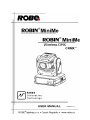
Robin MiniMe
Table of contents
1. Safety instructions.......................................................................................................... 3
2. Fixture exterior view ...................................................................................................... 5
3. Installation....................................................................................................................... 6
3.1 Connection to the mains............................................................................................. 6
3.2 Rigging the fixture....................................................................................................... 7
3.3 Positioning the Robin MiniMe . ................................................................................... 8
3.4 Using the mounting bracket .................................................................................... 10
3.5 Installing the wide-angle lens module ...................................................................... 11
3.6 DMX-512 connection................................................................................................. 12
3.7 Ethernet connection.................................................................................................. 13
3.8. Wireless DMX operation.......................................................................................... 14
4. Control menu map......................................................................................................... 15
5. Control menu ................................................................................................................ 18
5.1 Addressing (DMXA).................................................................................................. 18
5.2 Fixture information (Info)........................................................................................... 18
5.3 Personality (Pers)...................................................................................................... 19
5.4 Manual Control (Manual)........................................................................................... 20
5.5 Stand-alone (St Alone).............................................................................................. 20
5.6 Reset (Reset)............................................................................................................ 21
5.7 User Media (User Media).......................................................................................... 21
5.8 Special functions (Special)........................................................................................ 22
6. Keystones...................................................................................................................... 24
7. Using external HDMI input............................................................................................ 25
8. Error and information messages................................................................................. 25
9. Technical Specifications.............................................................................................. 26
10. Maintenance and cleaning.......................................................................................... 31
10.1 Replacing a fuse..................................................................................................... 31
11. ChangeLog . ................................................................................................................ 32
The Robin MiniMe was not designed for merged projection as due to
the nature of the light source, each projector can look slightly different.
FOR YOUR OWN SAFETY, PLEASE READ THIS USER MANUAL CAREFULLY
BEFORE POWERING OR INSTALLING YOUR ROBIN MiniMe !
Save it for future reference.
This device has left our premises in absolutely perfect condition. In order to maintain this condition and to
ensure a safe operation, it is absolutely necessary for the user to follow the safety instructions and warning
notes written in this manual.
The manufacturer will not accept liability for any resulting damages caused by the non-observance of this
manual or any unauthorized modification to the device.
Please consider that damages caused by manual modifications to the device are not subject to warranty.
The Robin MiniMe was designed for indoor use and it is intended for
professional application only. It is not for household use.
1. Safety instructions
DANGEROUS VOLTAGE CONSTITUTING A RISK OF ELECTRIC SHOCK IS PRESENT WITHIN THIS
UNIT!
Make sure that the available voltage is not higher than stated on the rear panel of the fixture.
This fixture should be operated only from the type of power source indicated on the marking label. If you are
not sure of the type of power supplied, consult your authorized distributor or local power company.
Always disconnect the fixture from AC power before cleaning, removing or installing the fuses, or any part.
The power plug has to be accessible after installing the fixture. Do not overload wall outlets and extension cords
as this canresult in fire or electric shock.
Do not allow anything to rest on the power cord. Do not locate this fixture where the cord may be damaged by
persons walking on it.
Make sure that the power cord is never crimped or damaged by sharp edges. Check the fixture and the power
cord from time to time.
Refer servicing to qualified service personnel.
This fixture falls under protection class I. Therefore this fixture has to be connected to
a mains socket outlet with a protective earthing connection.
Do not connect this fixture to a dimmer pack.
LED light emission. Risk of eye injury. Do not look into the beam at a distance of less
than 2 meters from the front surface of the product. Do not view the light output with
optical instruments or any device that may conncentrate the beam
If the fixture has been exposed to drastic temperature fluctuation (e.g. after transportation), do not switch it on
immediately. The arising condensation water might damage your device. Leave the device switched off until
it has reached room temperature.
Do not shake the fixture. Avoid brute force when installing
or operating the fixture.
This fixture was designed for indoor use only, do not expose this unit to rain or use near water.
When choosing the installation spot, please make sure that the fixture is not exposed to extreme heat, moisture,
dust or entertainment smoke (haze)
Air vents and slots in the fixture´s head and base are provided for ventilation, to ensure reliable operation of
the device and to protect it from overheating.
Do not block the light output with any object when the fixture is under operation.
The openings should never be covered with cloth or other materials, and never must be blocked.
This fixture should not be placed in a built-in installation unless proper ventilation is provided.
Only operate the fixture after having checked that the housing is firmly closed and all screws are tightly fastened.
Always use a secondary safety cable when mounting this fixture.
Do not block the front objective with any object when the fixture is under operation.
The fixture becomes very hot during operation. Allow the fixture to cool approximately 20 minutes prior to
manipulate with it.
Operate the fixture only after having familiarized with its functions. Do not permit operation by persons not
qualified for operating the fixture. Most damages are the result of unprofessional operation!
Please use the original packaging if the fixture is to be transported.
Please consider that unauthorized modifications on the fixture are forbidden due to safety reasons!
If this device will be operated in any way different to the one described in this manual, the product may suffer
damages and the guarantee becomes void. Furthermore, any other operation may lead to dangers like shortcircuit, burns, electric shock, crash etc.
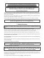
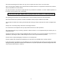
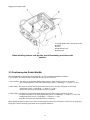
2. Fixture exterior view
1 - Moving head
2 - Arm
3 - Base
4 - Attachment point for safety cable
5 - Control board
6 - DMX Out (5-pin XLR)
7 - DMX In (5-pin XLR)
8 - Ethernet (RJ45)
9 - 2x USB input
10 - HDMI input
11 - Power Input
12 - Power output
3. Installation
Fixtures must be installed by a qualified electrician in accordance with all
national and local electrical and construction codes and regulations.
3.1 Connection to the mains
For protection from electric shock, the fixture must be earthed!
The Robin MiniMe is equipped with auto-switching power supply that automatically adjusts to any 50-60Hz AC
power source from 100-240 Volts.
Install a suitable plug on the power cord (if it is needed), note that the cores in the power cord are coloured
according to the following table. The earth has to be connected!
If you have any doubts about proper installation, consult a qualified electrician.
Core (EU)
Core (US)
Connection
Plug Terminal Marking
Brown
Black
Live L
Light blue
White
Neutral
N
Yellow/Green
Green
Earth
This device falls under class one and must be earthed (grounded)!
Design of the Robin MiniMe allows to connect several fixtures to AC mains power in one interconnected daisy
chain using power input and throughput connectors. Needed daisy chain cords are stated in the chapter
“Technical specifications “
The max. number of connected fixtures depends on the AC mains power voltage:
19 fixtures at power supply= 230V
16 fixtures at power supply= 208V
10 fixtures at power supply= 120V
Do not overload the supply line and the connecting leads.
Wiring and connection work must be carried out by qualified staff!
3.2 Rigging the fixture
A structure intended for installation of the fixture (s) must safely hold weight of the fixture(s) placed on it. The
structure has to be certificated to the purpose.
The fixture (fixtures) must be installed in accordance with national and local electrical and construction codes
and regulation.
For overhead installation, the fixture must be always secured with a safety wire
When rigging, derigging or servicing the fixture staying in the area below the installation place, on bridges,
under high working places and other endangered areas is forbidden.
The operator has to make sure that safety-relating and machine-technical installations are approved by an expert
before taking into operation for the first time and after changes before taking into operation another time.
The operator has to make sure that safety-relating and machine-technical installations are approved by a skilled
person once a year.
Allow the fixture to cool for ten minutes before handling.
The projector should be installed outside areas where persons may walk by or be seated.
IMPORTANT! OVERHEAD RIGGING REQUIRES EXTENSIVE EXPERIENCE, including calculating working
load limits, installation material being used, and periodic safety inspection of all installation materials and the
projector. If you lack these qualifications, do not attempt the installation yourself, but use a help of professional
companies.
CAUTION: Fixtures may cause severe injuries when crashing down! If you have doubts concerning the safety
of a possible installation, do not install the fixture!
The fixture has to be installed out of the reach of public.
The fixture must never be fixed swinging freely in the room.
When installing the device, make sure there is no highly inflammable
material (decoration articles, etc.) in a distance of min. 0.5 m.
.
CAUTION!
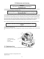
Use an appropriate clamp to rig the fixture on the truss.
Follow the instructions mentioned at the bottom of the base.
Make sure that the device is fixed properly! Ensure that the
structure (truss) to which you are attaching the fixtures is secure.
The fixture can be placed directly on the stage floor or rigged on a truss without altering its operation characte
ristics .
For securing a fixture to the truss install a safety wire that can hold at least 10 times the weight of the fixture.
Use only safety wire with screw-on carabine. Fasten the safety cable in the attachment point and around
the truss as shown on the picture.
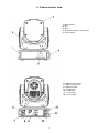
Rigging via omega holder:
1-Omega holder with a quarter-turn loks
2-Clamp
3-Trust
4-Attachment point
5-Safety wire
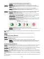
When installing fixtures side-by-side, avoid illuminating one fixture with
another!
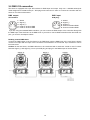
3.3 Positioning the Robin MiniMe
The Robin MiniMe is designed to be installed in one of four possible installation locations:
1. Front Table - the fixture is placed near the floor in front of the screen.
2. Front Ceiling - the fixture is suspended upside-down from the ceiling (truss) in front of the screen.
Set Ceiling Projection in the menu Personality ("Pers--->"LED Engi" --->"Ceil P"--->"On")
3. Rear Table - the fixture is placed near the floor behind the screen. Set Rear Projection in the menu
Personality ("Pers--->"LED Engi" --->"Rear P"--->"On")
Note that a special rear projection screen is required.
4. Rear Ceiling - the fixture is suspended upside-down from the ceiling (truss) behind the screen.
Set Rear Projection in the menu Personality ("Pers--->"LED Engi" --->"Ceil P"--->"On") and Ceiling Projection ("Pers--->"LED Engi" --->"Rear P"--->"On")
Note that a special rear projection screen is required.
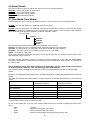
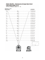
When determining the position of the fixture and projection screen, you will need to account for the projected
image size, which is directly proportional to the projection distance.
There is a chart of throw distance ratio of 3.5 : 1 to assist you in determining the ideal location for your
fixture.
Note: There is a tolerance among these numbers due to optical component variations. We recommend that if
you intend to permanently install the Robin MiniMe, you should physically test the projection size and distance
using the actual fixture before you permanently install it.
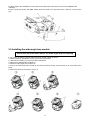
3.4 Using the mounting bracket
The mounting bracket allows simple mounting of the Robin MiniMe on the ceiling. The mounting bracket is
intended for horizontal mounting only.
IMPORTANT! Ceiling mounting requires extensive experience, including calculating
working load limits and installation material being used.
To fasten the Robin MiniMe on the ceiling via the mounting bracket, follow these steps:
1. Fasten the mounting bracket (1) on the ceiling (2) by means of the four screws (3). Check, that the stabilization screw (4) is screwed into mounting bracket.
Note The screws are not supplied with the mounting bracket, their length, diameter and a type of screws depends on conditions of given installation.
2. Insert a pivot (5) into the mounting point in the fixture base (6) and turn it a full 1/4-turn clockwise to lock.
Instal the second pivot.
3. Insert the fixture with both pivots (5) into circular slots under securing blades (8) and than move the fixture
towards the stabilization screw (4) until the pivots (5) reach the rectangular slots (7) and both securing blades
(8) snap into groove in the pivots.
4. Check the fastening of the fixture.
10
5. Gently tighten the stabilization screw until reaches the base of the fixture to prevent the MiniMe from
wobbling.
6. After connecting power and DMX cables place the cable cover (9) and secure it with an 1/4-turn screw
(10)
3.5 Installing the wide-angle lens module
Disconnect from the mains before the wide-angle module installing
If you need to install the optional wide-angle lens module, follow the steps:
1. Remove both top and button covers (1) from the fixture head.
2. Unscrew two screws (2) on the each side of the head.
3. Remove the standard lens module (3).
4. Place the wide-angle lens module (4).
5. Secure the wide-angle lens module on the fixture head by means of two screws (2) on each side of the
head.
6. Place back both top and button covers (1)
11
3.6 DMX-512 connection
The fixture is equipped with 5-pin XLR sockets for DMX input and output. Only use a shielded twisted-pair
cable designed for RS-485 and 5-pin XLR-plugs and connectors in order to connect the controller with the
fixture or one fixture with another.
DMX output
XLR sockets:
DMX input
XLR plug:
1 - Shield
2 - Signal (-)
3 - Signal (+)
4 - Used for wireless DMX
5 - Used for wireless DMX
1 - Shield
2 - Signal (-)
3 - Signal (+)
4 - Used for wireless DMX
5 - Used for wireless DMX
If you are using the standard DMX controllers, you can connect the DMX output of the controller directly with
the DMX input of the first fixture in the DMX-chain. If you wish to connect DMX-controllers with other XLR-outputs, you need to use adapter-cables.
Building a serial DMX-chain:
Connect the DMX-output of the first fixture in the DMX-chain with the DMX-input of the next fixture. Always
connect one output with the input of the next fixture until all fixtures are connected. Up to 32 fixtures can be
interconnected.
Caution: At the last fixture, the DMX-cable has to be terminated with a terminator. Solder a 120 Ω resistor
between Signal (–) and Signal (+) into a 5-pin XLR-plug and plug it in the DMX-output of the last fixture.
12
3.7 Ethernet connection
The fixtures on a data link are connected to the Ethernet with ArtNet communication protocol.The control software running on your PC (or light console) has to support Art-Net protocol.
Art-Net communication protocol is a 10 Base T Ethernet protocol based on the TCP/IP.Its purpose is to allow
transfer of large amounts of DMX 512 data over a wide area using standard network technology.
IP address is the Internet protocol address.The IP uniquely identifies any node (fixture) on a network.
The Universe is a single DMX 512 frame of 512 channels.
The Robin MiniMe is equipped with 8-pin RJ- 45 socket for Ethernet input.Use a network cable category 5 (with
four “twisted” wire pairs) and standard RJ-45 plugs in order to connect the fixture to the network.
RJ-45 socket (front view):
RJ-45 plug (front view):
1- TD+ 5- Not connected
2- TD-
6- RX
3- RX+
7- Not connected
4- Not connected
8- Not connected
Patch cables that connect fixtures to the hubs or LAN sockets are wired 1:1,that is,pins with the same numbers
are connected together:
1-12-2
3-3
4-4
5-5
6-6
7-7
8-8
If only the fixture and the computer are to be interconnected,no hubs or other active components are needed.
A cross-cable has to be used:
1-32-6
3-1
4-8
5-7
6-2
7-5
8-4
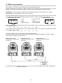
Connect the Ethernet inputs of all fixtures with the Ethernet network.
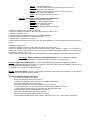
The option “ArtNet" has to be selected from the menu “Mode” at the fixture (DMXA 001-->Mode-->ArtNet).
Set IP address, NetMask and the Universe.
(DMX address=144)
IP addres=002.168.002.006
Universe=1
(DMX address=25)
IP addres=002.168.002.003
Universe=1
(DMX address=1)
IP addres=002.168.002.002
Universe=1
An advised PC setting: IP address: 002.xxx.xxx.xxx or 010.xxx.xxx.xxx (Different from fixture IP addresses)
NET mask: 255.0.0.0
13
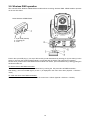
3.8. Wireless DMX operation
The external Robe Wireless CRMX-LB100 module allows receiving wireless DMX. CRMX module operates
on the 2.4 GHz band.
Robe Wireless CRMX-LB100
1 - 5-pin XLR (female)
2 - Locating pin
3 - Lock
Push in the 5-pin XLR plug (1) into 5-pin XLR sockit (4) and simultaneously locating pin (2) into hole (5) in the
fixture. In this way the wireless DMX module is connected with the fixture and prepared for operation.
NOTE: when you disconnect the DMX wireless module from fixture, press and hold lock (5) during getting the
wireless module out.
To link the fixture with DMX transmitter.
The fixture can be only linked with the transmitter by running the link procedure at DMX transmitter .
After linking , the level of DMX signal ( 0-100 %) is displayed in the menu item “Stat“ (Special -->Vireless ->Stat).
To unlink the fixture from DMX transmitter.
The fixture can be unlinked from receiver via the menu item “ Unlink“ (Special-->Vireless -->Unlink.).
14
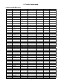
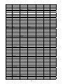
4. Control menu map
Default settings=Bold print
Level 1
Level 2
Level 3
DMXA
001
Mode
DMX
Level 4
Level 5
ArtNet
IP Addr
IP Ad1
000-255
:.
IP Ad4
000-255
IP NetM
Net M1
000-255
:
Net M4
000-255
Reset Addrese
DMX Addr
000-255
Info
ArtN Uni
000-255
000-255
POn Time
Total
Reset
LOn Time
Total
Reset
Air Fil
DMX In
R Ti
Aler P
10-300
Pan
0-255
:
Temp
Dimmer
0-255
Current
CPU
Head
Highest
CPU
Head
High Res
CPU
Head
Sw Ver
GE
IC-1
Pers
Pan Rev
On, Off
Tilt Rev
On, Off
P/T Mode
Speed
Time
P/T Feed
On, Off
BLC DMC
On, Off
Act BLC
P/T Mov
C Cal M
On, Off
Display
Turn
LED Engi
GRP Engi
On, Off
On/Off T
On, Off
Contrast
0-15
Backlight
0-15
Ceil P.
On, Off
Rear P.
On, Off
Aspect R
Keep AR
15
On, Off
Level 6
Level 7
Level 1
Level 2
Level 3
Level 4
Gobo Sel Mode
ABCD
Gobo Sel Mode
Numer
SS Gobo Swap T
0-30 s, 3 s
Ref Rate
50Hz, 60Hz
Optics M
Wide Optics
Level 5
None
Fans
Auto, High
Defaults
Manual
DMX Ctrll
Pan
0-255
:
LED Engi
Test Prg
Static
Dimr.
0-255
Ext Inp
On, Off
Keystone
0-255, 128 center
LED On/Off
On, Off
Pan
(0-255)
Tilt
(0-255)
Focus
(0-255)
Run
Dynamic
St Alone
Auto Run
Play Off
DMX Prg 1
:
DMX Prg 9
Pl DMX Prg
DMX Prg 1
:
DMX Prg 9
Rc DMX Prg
DMX Prg 1
:
DMX Prg 9
Reset
Reset GE
Reset P/T
Reset Focu
Reset All
User Media
No USB
Mirror Media
From Minime
To Minime
Mirror Program
From Minime
To Minime
Mirror Update
To Minime
Convert Inter
Delete Int. Me.
Special
RDM High
RDM Low
Wireless
Stat
Unlink
'HDMI Delay'
Off, On
Calib
Cal PTF
Pan C
0-255
Tilt C.
0-255
16
Level 6
Level 7
Level 1
Level 2
Level 3
Level 4
Level 5
Focu C.
0-255
Focu V
Focu H
Store
Cal Col
Hori Align
Red C
0-255
Green C
0-255
-3°.....+3°
Blue C
0-255
Gamma C
0-5
Store
Sw Upd
Hw Upd
MAC High
MAC Low
17
Level 6
Level 7
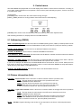
5. Control menu
The Robin MiniMe is equipped with 2-row LCD display which allows to set the fixture´s behaviour according to
your needs, obtain information on its operation, test its various parts and lastly program it, if it has to be used
in a stand-alone mode.
Control panel:
[ESCAPE] button used to leave the menu without saving changes.
[NEXT] , [PREV] buttons for moving between menu items and for value adjusting.
[ENTER] button used to enter the selected menu (menu item) and to confirm adjusted value.
After switching the fixture on, display shows current DMX address.
5.1 Addressing (DMXA)
Mode - Set operating mode. Use this menu item to set DMX operating mode (" DMX") or ArtNet operation mode
("ArtNet"). If the ArtNet mode is selected, DMX address (D 001) and Universe (U 000) are shown by rotation.
IP Addr - Set IP Address. Use this menu to set desired IP address of the fixture.
IP NetM - Set NetMask. Use this menu to set desired NetMask of the fixture.
Reset Addreses - Reset addresses. This menu item sets IP address, netmask and Artnet universe to default
values.
DMX Addr - Set DMX address. Use this menu item to set desired DMX start address of the fixture, which is
defined as the first channel from which the Robin MiniMe will respond to the controller.
If you set, for example, the address 23, the Robin MiniMe will use channels 23 - 54 for control. Please, be sure
that you do not have any overlapping channels in order to control each Robin MiniMe correctly and independently from any other fixture on the DMX data link.
ArtN Uni - Set ArtNet Universe. Use this menu item to set desired ArtNet Universe.
5.2 Fixture information (Info)
POn Time - Power on time. Select this menu to read the number of fixture operation hours.
Total - The item shows the total number of the operation hours since
the Robin MiniMe has been fabricated.
Reset - The item shows the number of the operation hours that the Robin MiniMe has been powered on since the counter was last reset.
In order to reset this counter to 0, press the [Enter] button twice.
LOn Time - Light source on time. Select this menu to read the number of the light LED source operation
hours.
Total - The item shows the total number of the LED source operation hours since
the Robin MiniMe has been fabricated.
Reset - The item shows the number of the LED source operation hours that the Robin MiniMe has been powered on since the counter was last reset.
In order to reset this counter to 0, press the [Enter] button twice.
Air Fil - Air filter. Regular cleaning of the air filter is very important for the fixture´s life and performance.
18
Dust, dirt and fog fluid residues reduces the fixture´s light output and cooling ability.
The two items of this menu help you to keep cleaning period of the air filter.
Aler P - Alert period. Cleaning schedule for the fixture depends on the operating
environment.
It is therefore impossible to specify accurate cleaning interval. This item allows
you to change the cleaning interval of the air filters. This "alert" value is 300 hours and it
is set as default. Inspect the fixture within its 300 hours of operation to see whether cleaning
is necessary. If cleaning is required, clean all air filters and change the value in this menu
on acceptable level. Min. level of alert period is 10 hours, max. is 300 hours.
R Ti - Remaining Time.The item allows you to read the time which remains to cleaning
air filters.The time period is set in the menu mentioned above.
Expired time period is signalled by a negative mark (-) at the time value and a warning
message on the display.
Clean the air filter and reset the counter by pressing the [Enter] button twice.
DMX In - DMX readout. The menu is used to read DMX values of each channel received by the fixture.
Temp - Temperature. The menu shows temperatures in the fixture.
Current - A current temperature in the fixture head and CPU.
Highest - A maximum temperature in the fixture head and CPU since the fixture has
been fabricated.
High Res - A maximum temperature in the fixture head and CPU since the counter
was last reset.
In order to reset this counter, press and hold both [NEXT] and [PREV] buttons
and the [Enter] button at the same time.
Sw Ver - Software versions. Select this item to read the software version of the fixture modules.
GE - A graphic engine
IC-1 - A pan/tilt and zoom module
5.3 Personality (Pers)
Pan Rev - Pan reverse. The item allows to invert pan movement.
Tilt Rev - Tilt reverse. The item allows to invert tilt movement.
P/T Mode - Pan and Tilt movement mode. Use this menu to set mode of the pan/tilt movement.
Speed - Both Pan and tilt will move with the same speed as adjusted at the channel 5
"Pan/Tilt speed, Pan/Tilt time".
Time – The pan and tilt will move with different speeds and they will come at
the same time to the end point of their tracks (pan and tilt use their optimal speeds).
Time of the pan/tilt movement (25.5 sec. max.) is set by the channel "Pan/Tilt speed, Pan/Tilt
time".
P/T Feed - Pan & Tilt Feedback. The menu item allows to return the mowing head to the required pan/tilt
position after changing the position by an external force if this option is set on.
Note. The Pan/Tilt Feedback should be permanent On, the option Off is not suitable for standard operation and
the head of the fixture can be damaged!
BLC DMC - Blackout during movement correction. Set this option on if you wish to close light
output during the time when the head goes to its correct position, which has been changed by an
external force.
Act Blc - Active blackout. Use this menu if you wish to close the light output during effect changes.
P/T Mov - The menu item allows to close light output while the pan/tilt coordinates
are changing.
C Cal M - Colour calibration mode. The function switches on/off the colour calibration mode. If the function
is active, a white colour (0-15 DMX) at the channel " Virtual colour Wheel" is set to 8000K.
Display - Display adjusting. This menu allows you to adjust the display behaviour.
Turn - This function turns the display by 180°. The display can be also turned by pressing and holding the [ESCAPE] button.
On/Off T - This function allows you to keep the display permanent on or turn it off
19
two minutes after last pressing any button on the control panel.
Contrast- Use this function to adjust contrast of the display (0-15).
Backlight- Use this function to adjust backlight of the display (0-15).
LED Engi - Led engine options. Enter the menu if you want to set special options for LED engine.
Ceil P - Ceiling projection. When this function is "On", the picture is top (bottom and left)
right reversed.
This function enables to project the image from a ceiling mounting of the MiniMe.
Rear P - Rear projection. When this function is "On", the picture is left (right) reversed.
This function enables to project the image to a rear projection screen.
GRP Engi - Graphic engine options. Enter the menu if you want to set special options for graphic engine.
Aspect R - Keeping Aspect ratio. If this function is "On", the fixture keeps native
aspect ratio of played pictures (videos).
If this function is "Off", all pictures (videos) are played in the aspect ration 16:10 regardless
of native aspect ratio of each picture (video).
Gobo Sel Mode - Gobo selection mode. The media files assigned to the DMX values can
be sorted either in alphabetical ( item ABCD) or numerical order (item Numer).
Default assigning is the alphabetical order.
SS Gobo Swap T - Slide Show gobo swap time. The option sets time period during which
a gobo stay in a position before changing at the "Gobos presentation" function (channel 17/
Digital gobo wheel/ DMX range of 251-252).
Ref Rate - Refresh rate. Select desired refresh rate 50Hz or 60Hz.
Optics M - Optics mode. The option " Wide Optics" corrects distortion of the image if
the Lens wide-angle 1:1.5 is used.
Fans - Fan mode. Use the menu to set the fixture fans to max. fan power mode ("High") or to the auto-control
mode ("Auto").
Defaults - The menu item allows to set all fixture parameters to the default (factory) values.
5.4 Manual Control (Manual)
DMX Ctrl - DMX channels control. Use the menu to manually control each channel effect.
LED Engi - LED Engine options
Ext Inp - Via this menu option is possible to activate the external input (HDMI).
Keystone - The item allows to use LED engine keystoning when the external input is active.
Led On/Off - The item allows to switch off LED engine when the external input is active.
5.5 Stand-alone (St Alone)
Auto Run - Presetting playback. This function allows you to select the program which will be played in the
stand-alone mode after switching the fixture on. Selected program will be played continuously in a loop.
PL DMX Prg - Play DMX program. Select this menu to run one of 9 programs which have been recorded via
the menu “Rc DMX Prg”. When the program is running, pressing the [ENTER] pauses its running.
Rc DMX Prg - Record DMX program. The menu allows you to record DMX data that receives the fixture and
then replay them again via the menu “PL. DMX Prg”. There is a menu of 9 programs which can be used for
recording DMX data.
Select desired program and press the [ENTER] to start recording. To stop recording, press the [ENTER]
again.
Recorded programs ca be copied to the USB memory stick (menu "User Media") and after that loaded into
another fixture (s).
20
5.6 Reset (Reset)
This option enables to index all effects and return them to their standard positions.
Reset GE - reset of the graphic engine module.
Reset P/T - reset of the pan/tilt module.
Reset Focu - reset of the focus module.
Reset All - reset of all fixture modules.
5.7 User Media (User Media)
Custom media files can be saved in the fixture memory or can be called from the external USB drive.
No USB - This item will appear if no USB flash drive is connected.
Init USB - This item will appear if an USB flash drive without desired folder structure is connected. Press [ENTER] to start initialization. Initilization process creates folder called ‘minime’ in the root folder of the USB flash
drive. Inside this folder are three subfolders: extmedia, intmedia, update.
Top level folder
minime
extmedia
intmedia
programs
update
Recommended and supported filesystem on the USB flash drive is FAT16
exmedia - the folder serves for media files which will be played directly from this folder.
intmedia - the folder serves for media files which will be loaded into fixture memory.
programs - the folder serves for recorded programs (St Alone--> Rc DMX).
update - the folder for update file.
These folders structure may be also created by means of your computer, but exactly the same names, order
and small letters have to be kept.
The folder exmedia (intmedia) serves for a collection of custom media files. In the folder, the Robin MiniMe
sorts files in alphabetical or numerical order and assigns them to DMX values. Max. number of media files in
the folder is 250.
We recommend to follow the 3-digit conventions for media files, where a 3-digit number is followed by
an underscore and a name e.g.: 001_mountains.jpg, 002_landscape.jpg.......
The numerical order is suitable in the case that you need to assign certain media files to specified DMX
values.
Example: The table below show differences in file DMX assignment between the alphabetical and numerical
sorting.
The table also includes file names without a 3-digit convention to illustrate their behaviour in the numerical
sorting.
Media file name
DMX value
at Alphabetical Sorting
DMX value
at Numerical Sorting
001_testfile1.jpg
1
1
020_testfile2.jpg
2
20
19_testfile3.jpg
3
19
3_testfile4.jpg
4
3
460_testfile5.jpg
5
Not Assigned*
testfile.jpg
6
Not Assigned**
* The 3-digit number has to be in the range of 001-250.
** The media file name does not contain any digit.
To use custom media files, you have tu set relevant DMX values on the channel 16 (Digital gobo wheel selection).
DMX
Function
0-31
Default-Factory Digital gobo wheel 32-63
Internal Custom Digital gobo wheel 64-95
External Custom Digital gobo wheel (USB memory stick)
21
Supported file formats are:
jpg for pictures (resolution up to 4096 x 4096 pixels)
mpeg4 and h264 for videos (resolution up to 1920 x1080 pixels, optimal 1280x800)
Note: the native resolution of the light projection engine is 1280x800 pixels, therefore optimal resolution for
pictures and videos is 1280x800 pixels.
Note: AVI, MOV etc. is a container with video and audio in it. For example, you can have AVI file with audio
encoded as mp3, video as mpeg2. This file cannot be played. Another AVI file can have audio as ogg vorbis
and video as h264. This file can be played. Whether the Robin MiniMe can play the file or not depends on the
encoding, not on the container.
Mirror Media - This menu allows to load files from the folder intmedia (on the USB memory stick) into the
fixture and vice versa.
From Minimi - the option copies custom media files from the fixture into USB memory stick
(custom files only).
To Minimi - the option copies custom media files from USB memory stick into the fixture.
There is 9.5 GB free space available for custom content in the fixture.
Note: Custom media files in the fixture memory will be overwritten.
Factory files stay without change.
Mirror Program - This menu allows to load programs from the folder programs (on the USB memory stick)
into the fixture and vice versa.
From Minimi - the option copies created programs (menu "St Alone") from the fixture into
USB memory stick.
To Minimi - the option copies programs from the USB memory stick into the fixture.
Note: Created programs in the fixture will be overwritten.
Convert Inter - The option converts custom pictures (only) in the fixture into optimal resolution (1280x800
pixels) for the Robe MiniMe. These converted pictures can be copied back to the USB memory stick (option
"Mirror Media"). Delete Int. Me. - This menu delete media files in the fixture´s memory.
To copy custom files into fixture
1. Connect the MiniMe to the mains.
2. Plug the USB flash drive into the fixture.
3. Initialize the USB flash drive (via menu "Init USB") and unplug it.
4. Plug the USB flash drive into computer.
5. Upload content into folder (intmedia) and unplug it.
6. Plug the USB flash drive back into the MiniMe.
7. Mirror content into the MiniMe (only intmedia) via menu "Mirror Media".
8. Unplug the USB flash drive from the MiniMe .
5.8 Special functions (Special)
RDM Low - This menu item shows the first part of the RDM identification code.
RDM High - This menu item shows the second part of the RDM identification code.
Wireless - Wireless DMX information. The menu allows to read some information about
Wireless DMX operation
Stat - Wireless status. Use the menu to read wireless DMX status.
Unlink - use this item to unlink fixture from wireless DMX.
HDMI Delay - HDMI delay. If this function is set off, there is not a 3 second delay when switching between
Internal and External HDMI input from DMX channel 6 "Special functions"(DMX range of 210-229 DMX).
Calib - Calibration menu. The menu allows fine adjustment of the pan, tilt, focus, white colour and Gamma
curve.
Cal PTF - Calibration of pan, tilt and focus.
Pan C - fine calibration of pan
Tilt C - fine calibration of tilt
22
Focu C - fine calibration of focus
Focu V - version of mechanical focus (should be set once more if
the light source has been changed).
Focu H - setting of focus hysteresis (should be set once more if
the light source has been changed).
Store - saves adjusted values into memory
Cal Col - Calibration of white colour and gamma curve.
Red C - a red saturation setting
Green C - a green saturation setting
Blue C - a blue saturation setting
Gamma C - a gamma setting
Store - saves adjusted values into memory
Calibration of pan/tilt/focus via the control board.
1. Disconnect DMX controller from the fixture and enter the "Calib" menu.
2. Enter the "Cal PTF" menu.
3. Use the [PREV] and [NEXT] to find "Pan" and press [ENTER].
4. Set desired value and save it by pressing [ENTER].
5. Repeat steps 3 and 4 for tilt and focus.
6. After calibrating all effects, find item "Store" and press [ENTER]. to save all adjusted values and reset the
fixture.
Calibration of white colour.
1. Disconnect DMX controller from the fixture and enter the "Calib" menu.
2. Enter the "Manual" menu, open shutter and dimmer and set "Cyan", "Magen" ,"Yellow", "Virt C" items to 0.
3. Enter the "Cal Col" menu. By means of the Red, Green and Blue items adjust the 8000K colour temperature
as exactly as possible (∆u´v´= 0).
4. After calibrating, find item "Store" and press [ENTER]. to save all adjusted colours and reset the fixture
Hori Align - Digital calibration of the RGB LED device. This function allows digitally
"align" RGB LED device in the fixture head in case, that it is placed askew.
Sw Upd - Graphical software update. The item starts update of the graphical software in the fixture.
Insert the USB flash drive with update file into USB port, select this option and press [ENTER]. Version of the
new software will be displayed, eg, v 003 ?.
If you want to run update, press [ENTER] again.
FW Upd - Firmware update. The item starts update of hardware functions like pan, tilt,focus...etc. and should
be performed after graphical software update
To perform software update of the fixture
1. Connect the MiniMe to the mains.
2. Plug the USB flash drive into the fixture.
3. Initialize the USB flash drive (via menu "Init USB") and unplug it.
4. Plug the USB flash drive into computer.
5. Download update file from Robe website into your computer.
Note: Please make sure the full name of the update file is minime_vxxx.tar.gz
(vxxx=version number) before you upload it into the USB flash drive.
6. Upload update file into folder (update) and unplug it.
7. Plug the USB flash drive back into the MiniMe.
8. Run graphical software update via menu "Sw Upd".
9. Run firmware update update via the menu " FW Upd" (if the notice " Do Fw Upd " appeared)
23
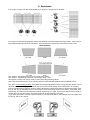
6. Keystones
If an image is output from the Robin MiniMe at an angle, the image may be skewed.
Two keystone channels (KeyStoning Vertical, KeyStoning Horizontal) adjust the image shape, aspect ratio is
kept. Default DMX value for both channels is 128, it means that no keystone correction has been used.
The channel " KeyStoning Vertical" turns image along X-axis.
The channel " KeyStoning Horizontal" turns image along Y-axis.
The keystone values can also be used to create interesting skewing effects.
Note: The horizontal keystone is not running while the Robin MiniMe displayes external HDMI source.
The option "Save AutoKeystoning" from DMX chart (channel Special functions, range 230-234) allows to save
adjusted values of the keystone channels and correct them automatically when head position is changed:
First use the Keystoning Vertical channel and the Kyestoning Horizontal channel to adjust image shape, after
that go and stay at this DMX range for 3 seconds to write keystoning values into memory. To activate AutoKeystoning, set channels Horizontal and Vertical Keystoning to 0. Now, if you move with the fixture head on
another place in the same plane, the image shape will be automatically corrected.
If you move the head in a tilt into oposite position, the image shape will be automatically corrected again and
the image will not be turned:
24
7. Using external HDMI input
If you want to use the external HDMI input of the fixture, you have to activate the external HDMI input via setting DMX value into range of 220-229 on the channel 6 (Special functions). If you want to return back to the
internal HDMI , set DMX value into range of 210-219 on this channel. Stay in desired DMX range for at least
3 seconds.
The horizontal keystone is not running while the Robin MiniMe displayes external HDMI source.
8. Error and information messages
DMX address blinks
It means that no DMX signal is received. Check DMX connectors and cables, check connection between the
fixture and the control desk.
Exclamation mark at sign "Art"
It means that no ArtNet signal is received. Check RJ 45 connectors and cables, check connection between the
fixture and the control desk.
Tilt Err
This message will appear after the reset of the fixture if the head´s magnetic-indexing circuit malfunctions (sensor failed or magnet is missing) or the stepping motor is defective or its driving IC on the PCB. The head is not
located in the default position after the reset.
Pan Err
This message will appear after the reset of the fixture if the head´s magnetic-indexing circuit malfunctions (sensor failed or magnet is missing) or the stepping motor is defective or its driving IC on the PCB. The head is not
located in the default position after the reset.
Focus Err
This message will appear after the reset of the fixture if the focus module malfunctions (sensor failed or magnet
is missing) or the stepping motor is defective or its driving IC on the PCB.
Temp Err
This message informs you that head temperature exceeded 70°C and light source has been switched off.
InnCom Err
This message informs you that communication between Raspberry and a pan/tilt PCB is faulty.
Ethernet Err
This message informs you that some ethernet error has occured e.g. faulty network card.
Need Hw Upd
This message informs you that hardware update has to be performed.
No proj. Reply
This message informs you that the projector in the fixture head does not communicate with the fixture base.
25
Clear air Filt.
This message informs you that the menu item remaining time ("R Ti ") in the menu "Information" is at 0 value.
Clean air filter and reset this counter.
Head Fan Err.
This message informs you that the small rear fan in the fixture head is faulty and the light source has been
switched off.
9. Technical Specifications
Electrical
Power supply:.........................electronic auto-ranging
Input voltage range:............... 100-240V, 50-60Hz
Fuse:.......................................T 3.15A/250V ~
Power consumption *:...............100W@230V,I=0.43A, power factor=0.87
*Allow for a deviation of +/-10%
Mains input: CE - max. 16A
cETLus - max. 10 A
Mains output: CE - max. 15A
cETLus - max. 9 A
Light engine
Light source: RGB LED device
Light output: 300 ANSI lumens
Rated light source life: 20000 hours
Digital gobo/image/video projection output
Hardware
Aspect ratio: 16:10
Native resolution: WXGA (1280x800)
Throw ratio: 3.5:1
Contrast ratio: 700:1
Display colours: 16.7 million colours
Raspberry Pi Model B 512MB RAM
Operating system
Linux
Graphic engine
Digital gobo wheel with gobos, images and videos
Gobo rotation and indexing
Video speed control
RGB or CMY colour mixing
Virtual colour wheel with pre-programmed 234 colours including 8000K white
Colour effect wheel with wide range of built-in colour effects (colour transitions and
cross-fades, multiple colour images, rainbow effects)
Effect wheel with wide range of graphic effects
Effect speed control
Horizontal/Vertical keystoning
Smooth dimmer
Shutter and strobe effects
Supported Image Format: JPG (up to 4096 x 4096 pixels)*
Supported Video Formats: MPEG4, h264 (resolution up to 1920x1060 pixels)*
*The native resolution of the light projection engine is 1280x800 pixels therefore optimal resolution for pictures
and videos is 1280x800 pixels.
26
Free space available for custom content
Focus
Strobe
Dimmer
9.5 GB
Motorized focus
Independent strobe effect with variable speed (0.3 - 20Hz)
Random strobe effect
Smooth dimmer from 0 - 100 %
Pan/Tilt
Control
Max. pan movement range: 450°
Max. tilt movement range: 270°
16 bit movement resolution
Automatic Pan/Tilt position correction
Remotely controllable speed of pan/tilt movement for easy programming
Upload and projection of custom artwork, photographs and videos
Live input via external HDMI
Setting & Addressing: two-row LCD display & 4 control buttons
Protocols: USITT DMX-512, RDM, ArtNet
Optional wireless external module available: CRMX™ technology from Lumen Radio
Control channels: 24
Ethernet port: Art-Net, ready for ACN
Recommended and supported filesystem on USB memory devices: FAT16
External Wireless DMX/RDM module (optional)
Compliance with USITT DMX-512 (1986 & 1990) and 512-A
Full DMX fidelity and frame integrity
Auto sensing of DMX frame rate and frame size
<5ms DMX latency
Operational frequency range of 2402-2480 MHz
Producer: LumenRadio
Connection
DMX data in/out: Locking 5-pin XLR
2 x USB 2.0 connector (series A)
ArtNet: RJ 45 (Neutrik Ethercon)
External video input: 1 x HDMI
AC power IN: Chassis connector Neutrik PowerCon, A-type, NAC3MPA
AC power OUT: Chassis connector Neutrik PowerCon, B-type, NAC3MPB
Rigging
Mounting points: one pair of 1/4-turn locks
Mounting horizontally or vertically via Omega holder
Temperatures
Ambient operating temperature : 0 - 40° C
Maximum housing temperature : 60° C
Distances
Min. distance from flammable surfaces: 0.5 m
Min. distance to projection surface: 0.8 m
27
Total heat dissipation
307 BTU/h (calculated)
90 Wh (calculated)
Weight (net):
5.7 kg
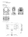
Dimensions (mm)
Mounting bracket (optional)
28
Accessories
Omega holder (P/N 99010420).......................1 piece
Optional accessories
(P/N 1098 0222) ROBE Wireless CRMX white
(P/N 10980197) Lens wide-angle 1:1.5 black
(P/N 10980211) Lens wide-angle 1:1.5 white
(P/N 1098 0208) Mounting bracket for MiniMe black
(P/N 1098 0209) Mounting bracket for MiniMe white
(P/N1305 1731) Mains Cable PowerCon In/open ended, 2m
(P/N 1305 1724) Mains Cable PowerCon In/Schuko, 2m
(P/N 1305 1725) Mains Cable PowerCon In/CEE 16A, 2m
(P/N 1305 1726) Mains Cable PowerCon In/US, 2m
(P/N 1305 1727) Daisy Chain PowerCon In/Out, EU, 2m
(P/N 1305 1728 ) Daisy Chain PowerCon In/Out, US, 2m
29
30
10. Maintenance and cleaning
DANGER !
Disconnect from the mains before starting any
maintenance work
A soft lint-free cloth moistened with any good glass cleaning fluid is recommended for objective lens, under no
circumstances should alcohol or solvents be used!
Never use alcohol or solvents for cleaning lenses in the moving head!
Use wet cloth only.
It is absolutely essential that the fixture is kept clean and that dust, dirt and smoke-fluid residues must not build
up on or within the fixture. Otherwise, the fixture‘s light-output will be significantly reduced. Regular cleaning will
not only ensure the maximum light-output, but will also allow the fixture to function reliably throughout its life.
The front lens may require monthly cleaning as smoke-fluid tends to building up residues, reducing the lightoutput very quickly. The cooling fans should be cleaned according to the situation (at least annually).
The interior of the base should be cleaned at least annually using a vacuum-cleaner or an air-jet.
More complicated maintenance and service operations are only to be carried out by authorized distributors.
Important! Check the air filter periodically and clean before it become clogged!
Clean the air filter placed in the rear side of the fixture head . Use a vacuum cleaner, compressed air or you
can wash them and put back dry.
After replacing the air filters, reset the elapsed time counter in the menu "Information" (Info--->Air Fil--->Ela
T).
1- fastening screws
2- rear cover of the head
3- Air filter
4- Velcro fastener
10.1 Replacing a fuse
This replacement has to be realized by a qualified person or ROBE service worker only.
Specifications are subject to change without notice.
August 29, 2014
31
11. ChangeLog
This section summarizes all types of changes in the user manual.
Version of the
manual
Date of issue
Description of changes
1.3
8/12/2013
DMX chart version 0.93 was renamed at version 1.0
1.4
7/01/2014
Added chapter " 7. Using external HDMI input."
Changes in technical specifications
DMX chart version 1.1 (change at channel 17)
1.5
15/01/2014
DMX chart version 1.2.
Changes in menu Personality and User Media
1.6
10/03/2014
Added chapters 3.4 Using the mounting bracket
3.5 Installing the wide-angle lens module
1.7
21/05/2014
Added menu items:
'Pers'->GRP Engi'->'Ref Rate'-> '50 Hz' / '60 Hz'.
'Pers'->GRP Engi'->'Optics M'->'Wide Optics' / 'None'
'Special'->'HDMI Delay'->'Delay Off' (no 3sec. delay) / 'Delay On'
'Special'->'Calib'->Hori Align'-> Range from -3.0° to 3.0°
1.8
04/09/2014
Added menu item:
'DMXA'->'Reset Addreses'.
New error messages:
No proj. reply
Head Fan Err
DMX chart version 1.3 (change at channel 17-Video Speed Control)
32
DMX protocol
Robin MiniMe - DMX protocol, version 1.3
Channel
DMX
Value
0 - 255
Pan movement by 450°
0 - 255
Fine control of pan movement
proportional
Pan fine
2
proportional
Tilt
3
0 - 255
Tilt movement by 270°
proportional
Tilt fine
4
0 - 255
Fine control of tilt movement
proportional
Pan/Tilt speed , Pan/Tilt time
5
0
1
2 - 255
2 - 255
Standard mode
Max. Speed Mode
Pan/Tilt speed mode
Speed from max. to min.
Pan/Tilt time mode
Time from 0.2 s to 25.5 sec.
step
step
proportional
proportional
Special functions
6
0-49
50 - 59
60 - 69
70 - 79
80 - 89
90-94
95-99
100-104
105-109
110 - 129
130-134
135-139
140 - 149
150 - 179
180 - 189
190 - 199
200 - 209
210-219
220-229
230-234
235 - 255
8
Type of
control
Pan
1
7
Function
To activate following functions, stop in DMX value for at least 3 s
and shutter must be closed at least 3 sec. („Shutter,Strobe”
channel 23 must be at range: 0-31 DMX). Corresponding menu
items are temporarily overriden).
Reserved
Pan/Tilt speed mode
Pan/Tilt time mode
Blackout while pan/tilt moving
Disabled blackout while pan/tilt moving
Ceiling projection On
Ceiling projection Off
Rear projection On
Rear projection Off
Reserved
To activate following functions, stop in DMX value for at least 3
seconds.
Keep aspect ratio On
Keep aspect ratio Off
Pan/Tilt reset
Reserved
Focus reset
Graphic engine reset(software update executing)
Total reset
Internal HDMI
External HDMI
Save AutoKeystoning
Reserved
Digital zoom
0-127 Zoom from min. -->real size
128
real size (default)
129-255 Zoom from real size -->max.
Focus
0 - 255
step
step
step
step
step
step
step
step
step
step
step
step
step
step
step
step
step
proportional
step
proportional
Continuous adjustment from far to near
Page 1
proportional
DMX protocol
Channel
DMX
Value
9
0-255
10
0 - 255
11
0 - 255
Function
Keystoning Vertical
Vertical keystoning (128 Default)
Keystoning Horizontal
Horizontal keystoning (128 Default)
Cyan
Cyan (white-->full cyan)
Type of
control
proportional
proportional
proportional
Magenta
12
0 - 255
Magenta (white-->full magenta)
proportional
Yellow
13
0 - 255
Yellow (white-->full yellow)
proportional
Virtual colour wheel
14
0-15
16
17-55
56
57-95
96
97-134
135
136-174
175
176-214
215
216-246
247
248-255
White (8000K)
Blue
Blue ---> Cyan
Cyan
Cyan ---> Green
Green
Green ---> Yellow
Yellow
Yellow ---> Red
Red
Red ---> Magenta
Magenta
Magenta ---> Blue
Blue
Reserved
step
step
proportional
step
proportional
step
proportional
step
proportional
step
proportional
step
proportional
step
Colour Effect wheel
15
0
1
2
3
4
5
6
7
8
9
10
11
12
13
14
15
16
17
18
19
20
21
No function
Static effects
Horizontal linear shade, white-->black
Horizontal Linear shade, black-->white
Vertical linear shade, black-->white
Vertical linear shade, white-->black
Diagonal shade, white -->black
Diagonal shade, black -->white
Horizontal linear shade, white-->red
Horizontal Linear shade, red-->white
Vertical linear shade, red-->white
Vertical linear shade, white-->red
Diagonal shade, white -->red
Diagonal shade, red -->white
Horizontal linear shade, white-->green
Horizontal Linear shade, green-->white
Vertical linear shade, green-->white
Vertical linear shade, white-->green
Diagonal shade, white -->green
Diagonal shade, green -->white
Horizontal linear shade, white-->blue
Horizontal Linear shade, blue-->white
Vertical linear shade, blue-->white
Page 2
step
step
step
step
step
step
step
step
step
step
step
step
step
step
step
step
step
step
step
step
step
step
DMX protocol
Channel
DMX
Value
22
23
24
25
26
27
28
29
30
31
32
33
34
35
36
37
38
39
40
41
42
43
44
45
46
47-49
50
51
52
53
54
55
56
57
58
59
60
61
62
63
64
65
65
66-69
70
71
72
73
74
Function
Vertical linear shade, white-->blue
Diagonal shade, white -->blue
Diagonal shade, blue -->white
Horizontal linear shade, white-->cyan
Horizontal Linear shade, cyan-->white
Vertical linear shade, cyan-->white
Vertical linear shade, white-->cyan
Diagonal shade, white -->cyan
Diagonal shade, cyan -->white
Horizontal linear shade, white-->magenta
Horizontal Linear shade, magenta-->white
Vertical linear shade, magenta-->white
Vertical linear shade, white-->magenta
Diagonal shade, white -->magenta
Diagonal shade, magenta -->white
Horizontal linear shade, white-->yellow
Horizontal Linear shade, yellow-->white
Vertical linear shade, yellow-->white
Vertical linear shade, white-->yellow
Diagonal shade, white -->yellow
Diagonal shade, yellow -->white
RGBW shades
CMYW shades
RGBY shades
RMBG shades
Reserved
Dynamic effects
Colour changing black -->white, slowly
Colour changing black -->white, fast
Colour changing red -->white, slowly
Colour changing red -->white, fast
Colour changing green -->white, slowly
Colour changing green -->white, fast
Colour changing blue -->white, slowly
Colour changing blue -->white, fast
Colour changing yellow -->white, slowly
Colour changing yellow -->white, fast
Colour changing magenta -->white, slowly
Colour changing magenta -->white, fast
Colour changing cyan -->white, slowly
Colour changing cyan -->white, fast
Colour changing (slow) red -->green -->blue -->yellow
Colour changing (fast) red -->green -->blue -->yellow
Colour changing (fastest) red -->green -->blue -->yellow
Reserved
Horizontal linear shade, white-->black and vice versa, slowly
Horizontal linear shade, white-->black and vice versa,fast
Vertical linear shade, white-->black and vice versa, slowly
Vertical linear shade, white-->black and vice versa, fast
Diagonal shade, black -->white and vice versa, slowly
Page 3
Type of
control
step
step
step
step
step
step
step
step
step
step
step
step
step
step
step
step
step
step
step
step
step
step
step
step
step
step
step
step
step
step
step
step
step
step
step
step
step
step
step
step
step
step
step
step
step
step
step
DMX protocol
Channel
DMX
Value
75
76
77
78
79
80
81
82
83
84
85
86
87
88
89
90
91
92
93
94
95
96
97
98
99
100
101
102
103
104
105
106
107
108
109
110
111
112
113
114
115
116
117
118
119
120
121
122
123
124
Function
Diagonal shade, black -->white and vice versa, fast
Shade black -->white, slow rotation, clockwise
Shade black -->white, fast rotation, clockwise
Shade black -->white, slow rotation, anticlockwise
Shade black -->white, fast rotation, anticlockwise
Horizontal linear shade, white-->red and vice versa, slowly
Horizontal linear shade, white-->red and vice versa,fast
Vertical linear shade, white-->red and vice versa, slowly
Vertical linear shade, white-->red and vice versa, fast
Diagonal shade, red -->white and vice versa, slowly
Diagonal shade, red -->white and vice versa, fast
Shade red -->white, slow rotation, clockwise
Shade red -->white, fast rotation, clockwise
Shade red -->white, slow rotation, anticlockwise
Shade red -->white, fast rotation, anticlockwise
Horizontal linear shade, white-->green and vice versa, slowly
Horizontal linear shade, white-->green and vice versa,fast
Vertical linear shade, white-->green and vice versa, slowly
Vertical linear shade, white-->green and vice versa, fast
Diagonal shade, green -->white and vice versa, slowly
Diagonal shade, green -->white and vice versa, fast
Shade green -->white, slow rotation, clockwise
Shade green -->white, fast rotation, clockwise
Shade green -->white, slow rotation, anticlockwise
Shade green -->white, fast rotation, anticlockwise
Horizontal linear shade, white-->blue and vice versa, slowly
Horizontal linear shade, white-->blue and vice versa,fast
Vertical linear shade, white-->blue and vice versa, slowly
Vertical linear shade, white-->blue and vice versa, fast
Diagonal shade, blue -->white and vice versa, slowly
Diagonal shade, blue -->white and vice versa, fast
Shade blue -->white, slow rotation, clockwise
Shade blue -->white, fast rotation, clockwise
Shade blue -->white, slow rotation, anticlockwise
Shade blue -->white, fast rotation, anticlockwise
Horizontal linear shade, white-->cyan and vice versa, slowly
Horizontal linear shade, white-->cyan and vice versa,fast
Vertical linear shade, white-->cyan and vice versa, slowly
Vertical linear shade, white-->cyan and vice versa, fast
Diagonal shade, cyan -->white and vice versa, slowly
Diagonal shade, cyan -->white and vice versa, fast
Shade cyan -->white, slow rotation, clockwise
Shade cyan -->white, fast rotation, clockwise
Shade cyan -->white, slow rotation, anticlockwise
Shade cyan -->white, fast rotation, anticlockwise
Horizontal linear shade, white-->magenta and vice versa, slowly
Horizontal linear shade, white-->magenta and vice versa,fast
Vertical linear shade, white-->magenta and vice versa, slowly
Vertical linear shade, white-->magenta and vice versa, fast
Diagonal shade, magenta -->white and vice versa, slowly
Page 4
Type of
control
step
step
step
step
step
step
step
step
step
step
step
step
step
step
step
step
step
step
step
step
step
step
step
step
step
step
step
step
step
step
step
step
step
step
step
step
step
step
step
step
step
step
step
step
step
step
step
step
step
step
DMX protocol
Channel
DMX
Value
125
126
127
128
129
130
131
132
133
134
135
136
137
138
139
140
141
142
143
144
145
146
147
148
149
150
151
152
153
154
155
156
157
158
159
160
161
162
163
164
165
166
167
168
169
170
171
172
173
174
Function
Diagonal shade, magenta -->white and vice versa, fast
Shade magenta -->white, slow rotation, clockwise
Shade magenta -->white, fast rotation, clockwise
Shade magenta -->white, slow rotation, anticlockwise
Shade magenta -->white, fast rotation, anticlockwise
Horizontal linear shade, white-->yellow and vice versa, slowly
Horizontal linear shade, white-->yellow and vice versa,fast
Vertical linear shade, white-->yellow and vice versa, slowly
Vertical linear shade, white-->yellow and vice versa, fast
Diagonal shade, yellow -->white and vice versa, slowly
Diagonal shade, yellow -->white and vice versa, fast
Shade yellow -->white, slow rotation, clockwise
Shade yellow -->white, fast rotation, clockwise
Shade yellow -->white, slow rotation, anticlockwise
Shade yellow -->white, fast rotation, anticlockwise
RGBW shades, slow rotation , clockwise
RGBW shades, fast rotation ,clockwise
RGBW shades, slow rotation , anticlockwise
RGBW shades, fast rotation ,anticlockwise
Random colours slowly, black between colours
Random colours fast, black between colours
Random colours slowly, white between colours
Random colours fast, white between colours
Random colours slowly
Random colours fast
Horizontal black shade -->random colour, slowly
Horizontal black shade -->random colour, fast
Vertical black shade -->random colour, slowly
Vertical black shade -->random colour, fast
Diagonal black shade -->random colour, slowly
Diagonal black shade -->random colour, fast
Black shade -->random colour, slow rotation ,clockwise
Black shade -->random colour, fast rotation ,clockwise
Black shade -->random colour, slow rotation ,anticlockwise
Black shade -->random colour, fast rotation ,anticlockwise
Random colour in two corners, slow rotation, clockwise
Random colour in two corners, fast rotation, clockwise
Random colour in two corners, slow rotation, anticlockwise
Random colour in two corners, fast rotation, anticlockwise
Random colour in four corners, slow rotation, clockwise
Random colour in four corners, fast rotation, clockwise
Random colour in four corners, slow rotation, anticlockwise
Random colour in four corners, fast rotation, anticlockwise
Horizontal colour transition, slowly, random
Horizontal colour transition, fast, random
Vertical colour transition, slowly, random
Vertical colour transition, fast, random
Diagonal colour transition, slowly
Diagonal colour transition, fast
Horizontal/Vertical/Diagonal colour transition slowly
Page 5
Type of
control
step
step
step
step
step
step
step
step
step
step
step
step
step
step
step
step
step
step
step
step
step
step
step
step
step
step
step
step
step
step
step
step
step
step
step
step
step
step
step
step
step
step
step
step
step
step
step
step
step
step
DMX protocol
Channel
DMX
Value
Function
175
Horizontal/Vertical/Diagonal colour transition fast
176-255 Reserved
Type of
control
step
Digital gobo wheel selection
16
0-31
32-63
64-95
96-255
Default-Factory Digital gobo wheel
Internal Custom Digital gobo wheel
External Custom Digital gobo wheel (USB memory stick)
Reserved (for future functions)
0
1-250
Open
Gobos/videos (by one DMX value:1,2,3…...250)
step
step
step
Digital gobo wheel
17
The following distribution serves for factory gobos/videos only
Black and white gobos (by one DMX value: 1, 2, 3…..59)
1-59
60-202 Colour pictures (by one DMX value: 60, 61, 62…..202)
203-216 Animations (by one DMX value: 203, 204, 2050…216)
To activate following two functions, set a transition effect (1-48)
at Effect Wheel - channel 21
Gobos presentation (gobos selected randomly)
251
Gobos presentation (gobos selected in alphabetical order)
252
253-255 Reserved
step
proportional
proportional
proportional
proportional
step
step
Video speed control
18
0
1
2-127
128-255
Original speed
Pause
Speed from min. (1/4 of original speed) to original speed
Speed from original to max. (4x original speed)
step
step
proportional
proportional
Digital gobo indexing and rotation
19
0 - 127
128-191
192-193
194- 255
Gobo indexing
Forwards gobo rotation from fast to slow
No rotation
Backwards gobo rotation from slow to fast
proportional
proportional
step
proportional
Digital gobo gobo indexing and rotation fine
20
0-255
Fine indexing (rotation)
proportional
Effect wheel
21
0
1
2
3
4
5
6
7
8
9
10
11
12
13
14
The following effects are controlled by means of the "Effect
speed/Time" channel below. Type of control is stated in the
column on the right.
Open position (hole)
Transition effects between two gobos (pictures)
Random transition
Transition with blending
Transition from left --> right, horizontally
Transition from right --> left, horizontally
Stripe transition from left --> right, horizontally
Stripe transition from right -->left, horizontally
3-stripe transition from left-->right, horizontally
3-stripe transition from right-->left, horizontally
6-stripe transition from left-->right, horizontally
6-stripe transition from right-->left, horizontally
Transition up --> down, vertically
Transition down -->up, vertically
Stripe transition up --> down, vertically
Stripe transition down -->up, vertically
Page 6
step
1
1
1
1
1
1
1
1
1
1
1
1
1
1
DMX protocol
Channel
DMX
Value
15
16
17
18
19
20
21
22
23
24
25
26
27
28
29
30
31
32
33
34
35
36
37
38
39
40
41
42
43
44
45
46
47
48
49-79
80
81
82
83
84
85
86
87
88
89
90-99
100
101
102
Function
3-stripe transition up-->down, vertically
3-stripe transition down-->up, vertically
6-stripe transition up-->down, vertically
6-stripe transition down-->up, vertically
Transition 2 from left --> right, horizontally (diffusion edge)
Transition 2 from right --> left, horizontally (diffusion edge)
Transition 2 up --> down, vertically (diffusion edge)
Transition 2 down -->up, vertically (diffusion edge)
Iris transition out--> in
Iris transition in--> out
Iris transition out--> in (Diffusin edge)
Iris transition in--> out (Diffusion edge)
Iris transition 3 out--> in (more diffusion edge)
Iris transition 3 in--> out (more diffusion edge)
Moving transition from left --> right
Moving transition from left --> right
Moving transition up --> down
Moving transition from down --> up
Drop transition
Simple transition
Pixel transition
Transition via blending
Transition with white output
Crossing transition
Picture in picture transition
Direct transition
Transition with vertical rotation
Transition with horizontal rotation
Transition with diagonal rotation
Transition with diagonal rotation-opposite direction
Zoom out transition
Zoom in transition
Zoom transition in horizontal direction
Zoom transition in vertical direction
Reserved
Effects applied at one gobo (picture)
Kaleidoscope 1
Kaleidoscope 2
Kaleidoscope 3
Kaleidoscope 4
Kaleidoscope 5
Sunflower Kaleidoscope (coarse)
Sunflower Kaleidoscope (soft)
Sunflower kaleidoscope (slow)
Sunflower kaleidoscope (faster)
Sunflower kaleidoscope (fastest)
Reserved
Circle Iris in/out
Circle Iris in/out (diffusion edge)
Vertical Ellipse Iris in/out
Page 7
Type of
control
1
1
1
1
1
1
1
1
1
1
1
1
1
1
1
1
1
1
1
1
1
1
1
1
1
1
1
1
1
1
1
1
1
1
3
3
3
3
3
3
3
4
4
4
2
2
2
DMX protocol
Channel
DMX
Value
Function
103
104
105
106
107
108
109-179
Horizontal Ellipse Iris in/out
Reserved
Positive/negative (black and white)
White/negative (black and white)
Positive/negative (coloured)
Pixeling
Reserved
Manual effects
180
Circular Iris
181
Elliptical Iris -vertical
182
Elliptical Iris-horizontal
183
Black mask
184
Inverse black mask
185
White mask
186
Inverse white mask
187
Gobo/video movement in horizontal (X) axis
188
Gobo/video movement in vertical (Y) axis
189
Reserved
190
Crossfade effect
191
Addition effect
192
Substraction effect
193
Multiplication effect
194
Minimum effect
195
Maximum effect
196-255 Reserved
Type of
control
2
2
2
2
2
5
5
5
6
6
6
6
7
7
8
8
8
8
8
8
Effect Speed/Time
22
Type of control 1
0
Presentation* (time=0.8 sec)
1-250 Time from 0,1 sec. to 25 sec.
251-255 Stop
*Presentation serves for showing effect
Type of control 2
0
Presentation (time=0.8 sec)
1-126 Time from 0,1 sec. to 12,6 sec.
127-128 Stop
129-254 Time from 12.6 sec to 0.1 sec. - opposite direction
255
Stop
step
proportional
step
step
proportional
step
proportional
step
0
1-255
Type of control 3
Presentation
Effect speed from min. to max.
proportional
0
1-255
Type of control 4
Presentation (4 corners)
Number of corners from min. to max.
proportional
0
1-255
Type of control 5
Open
Iris from open to close
step
step
step
proportional
Page 8
DMX protocol
Channel
DMX
Value
0
1-255
Function
Type of control 6
Open
Mask effect from min. level to max. level
Type of control 7
0-127 Movement from edge to centre
128
Centre
129--255 Movement from centre to edge
0-255
Type of
control
step
proportional
proportional
step
proportional
Type of control 8
Continuous effect changing
proportional
Shutter/ strobe
23
0 - 31
32 - 63
64 - 95
96 - 127
128 - 143
144 - 159
160 - 191
192 - 223
224 - 255
Shutter closed
Shutter open
Strobe-effect from slow to fast
Shutter open
Opening pulse in sequences from slow to fast
Closing pulse in sequences from fast to slow
Shutter open
Random strobe-effect from slow to fast
Shutter open
step
step
proportional
step
proportional
proportional
step
proportional
step
Dimmer
24
0 - 255
Dimmer intensity from 0% to 100%
Page 9
proportional
33