1
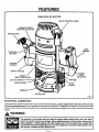
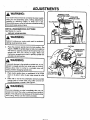
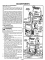
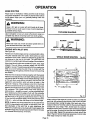
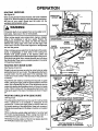
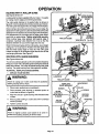
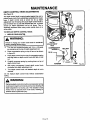
p
i
n
i
SW/A/ S
OWNER'S
MANUAL
MODEL NO.
315.275110
CAUTION:
Read and follow
CRRFTSMRN°
ALL safety rules
Industrial Electronic
and instructions
before operating
this equipment.
I
I
I
Thank You for Buying
Craftsman Tools
Plunge Router
Double Insulated
Warranty
Introduction
Unpacking
Features
Adjustments
Operation
Maintenance
Repair Parts
®
Sold by SEARS, ROEBUCK AND CO., Hoffman Estates, IL 60179 U.S.A.
972000-290
10-00
Printed In U.S.A.
RULES FOR SAFE OPERATION
DOUBLE INSULATION
is a safety concept in electric
power tools which eliminates the need for the usual
three wire grounded power cord and grounded supply
system. Wherever there is electric current in the tool
there are two complete sets of insulation to protect the
user. All exposed metal parts are isolated from internal
metal motor components with protecting insulation.
IMPORTANTServicing of a tool with double insulation
requires extreme care and knowledge of the system
and should be performed only by a qualified service
technician. For service we suggest you return the tool
to your nearest Sears Store for repair. Always use
original factory replacement parts when servicing.
WARNING:
WARNING:
Do not attempt to operate this tool until you have
read thoroughly and understand completely all
instructions, safety rules, etc. contained in this
manual. Failure to comply can result in accidents
involving fire, electric shock, or serious personal
injury. Save owner's manual and review frequently
for continuing safe operation, and instructing others
who may use this tool.
READ ALL INSTRUCTIONS
1.
KNOW
YOUR
POWER
TOOL.
Read owner's
2.
manual carefully. Learn its applications
and
limitations as well as the specific potential
hazards related to this tool.
GUARD
AGAINST
ELECTRICAL
SHOCK
by preventing
body contact with grounded
surfaces. For example: Pipes, radiators, ranges,
refrigerator enclosures.
3.
4.
KEEP GUARDS
IN PLACE
order.
KEEP WORK AREA CLEAN.
and benches invite accidents.
DANGEROUS
and in working
6.
Don't use power tool in damp or wet locations or
expose to rain, Keep work area well lit.
KEEP CHILDREN
AND VISITORS
AWAY.
7.
All visitors should wear safety glasses and be
kept a safe distance from work area. Do not let
visitors contact tool or extension cord.
STORE
IDLE TOOLS.
When not in use tools
ENVIRONMENT.
should be stored in a dry and high or locked-up
place - out of the reach of children.
10.
13.
14.
AVOID
9.
12.
Cluttered areas
5.
8.
11.
DON'T FORCE
TOOL. It will do the job better
and safer at the rate for which it was designed.
USE RIGHT
TOOL.
Don't force small tool or
attachment to do the job of a heavy duty
Don't use tool for purpose not intended
example - A circular saw should never be
for cutting tree limbs or logs.
WEAR
PROPER
APPAREL.
Do not
15.
16.
17.
18.
tool.
- for
used
19.
wear
loose clothing or jewelry that can get caught in
tool's moving parts and cause personal injury.
Rubber
gloves and non-skid footwear
are
_k
recommended when working outdoors. Wear
protective hair covering to contain long hair and
keep it from being drawn into nearby air vents.
ALWAYS
WEAR
SAFETY
GLASSES.
Everyday eyeglasses have only impact-resistant
lenses; they are NOT safety glasses.
PROTECT YOUR LUNGS. Wear a face or
dust mask if operation is dusty.
PROTECT YOUR HEARING. Wear hearing
protection during extended periods of operation.
DON'T ABUSE CORD. Never carry tool by
cord or yank it to disconnect from receptacle.
Keep cord from heat, oil and sharp edges.
SECURE WORK. Use clamps or a vise to hold
work. Both hands ar# needed to operate the
tool.
DON'T OVERREACH. Keep proper footing and
balance at all times. Do not use on a ladder or
unstable support.
MAINTAIN TOOLS WITH CARE. Keep tools
sharp at all times, and clean for best and safest
performance. Follow instructions for lubricating
and changing accessories.
DISCONNECT
TOOLS. When not in use, before servicing, or when changing attachments,
blades, bits, cutters, etc., all tools should be
disconnected from power supply.
REMOVE
ADJUSTING
KEYS
AND
WRENCHES.
Form habit of checking to see
that keys and adjusting wrenches are removed
from tool before turning it on.
Look
for this
symbol toYour
pointsafety
out important
safety
It
means
attention!!!
is revolved.
Page 2
precautions.
]
RULES FOR SAFE OPERATION (Continued)
20. AVOID ACCIDENTAL
STARTING. Don't carry
plugged-in tools with finger on switch. Be sure
switch is off when plugging in.
21. MAKE SURE YOUR EXTENSION
CORD IS
IN GOOD CONDITION. When usingan extension
cord, be sure to use one heavy enough to carry the
current your product willdraw. An undersized cord
will cause a drop in line voltage resulting in loss of
power and overheating. A wire gage size (A.W.G.)
of at least 14 is recommended for an extension
cord 25 feet or less in length. A cord exceeding 25
feet is not recommended. If in doubt, use the next
heavier gage. The smal_r the gage number, the
heavier the cord.
22. OUTDOOR USE EXTENSION CORDS. When
tool is used outdoors, use only extension cords
suitable for use outdoors.Outdoor approved cords
are marked with the suffix W-A, for example SJTW-A or SJOW-A.
23. KEEP CUTTERS
CLEAN
AND SHARP.
Sharp cutters minimize stalling and kickback.
24. KEEP HANDS
AWAY
FROM CUTTING
AREA. Keep hands away from cutters. Do not
reach underneath work while cutter is rotating.
Do not attempt to remove material while cutter is
rotating.
25. NEVER
USE
IN
AN
EXPLOSIVE
ATMOSPHERE.
Normal sparking of the motor
could ignite fumes.
26. INSPECT TOOL CORDS PERIODICALLY
and if damaged, have repaired at your nearest
Sears Repair Center. Stay constantly aware of
cord location.
27. INSPECT
EXTENSION
CORDS PERIODICALLY and replace if damaged.
28. KEEP HANDLES DRY, CLEAN, AND FREE
FROM OIL AND GREASE. Always use a clean
cloth when cleaning. Never use brake fluids, gasoline, petroleum-based products or any strong solvents to clean your tool.
29. STAY ALERT. Watch what you are doing and
use common sense. Do not operate tool when
you are tired. Do not rush.
30. CHECK
DAMAGED
PARTS. Before further
use of the tool, a guard or other part that is
damaged should be carefully checked to determine that it will operate properly and perform its
intended function. Check for alignment of moving
parts, binding of moving parts, breakage of parts,
mounting, and any other conditions that may affect its operation. A guard or other part that is
damaged should be properly repaired or replaced
by an authorized service center unless indicated
elsewhere in this instruction manual.
D_
31. DO NOT USE TOOL IF SWITCH DOES NOT
TURN
IT ON AND OFF. Have defective
switches replaced by an authorized service center.
32. INSPECT FOR and remove all nails from lumber
before routing.
33. DRUGS, ALCOHOL,
MEDICATION.
Do not
operate tool while under the influence of drugs,
alcohol, or any medication.
34. WHEN SERVICING USE ONLY IDENTICAL
CRAFTSMAN
REPLACEMENT
PARTS.
35. POLARIZED
PLUGS. To reduce the risk of
electric shock, this tool has a polarized plug (one
blade is wider than the other). This plug will fit in a
polarized outlet only one way. If the plug does not
fit fully in the outlet, reverse the plug. If it still does
not fit, contact a qualified electrician to install the
proper outlet. Do not change the plug in any way.
36. DO NOT USE TOOL UNDER
"BROWNOUT" OR OTHER LOW VOLTAGE CONDITIONS. Also, do not use with any device that
could cause the power supply voltage to change.
37. WHEN
USING THIS
ROUTER
WITH A
ROUTER TABLE, HELP PREVENT
POSSIBLE SERIOUS INJURY BY KEEPING THE
CUTTER GUARDED
AT ALL TIMES. Use
only router tables, with guards, that have been
designed for use on touters that are of this type,
size, and weight.
38. SAVE THESE INSTRUCTIONS.
Review them
frequently and use them to instruct others who
may use this tool. If you loan someone this tool,
loan them these instructions also.
_t
WARNING:
Some dust created by power sanding, sawing, grinding,
drilling, and other construction
activities contains
chemicals known to cause cancer, birth defects or
other reproductive harm. Some examples of these
chemicals are:
• lead from lead-based
paints,
• crystalline silica from bricks and cement and other
masonry products, and
• arsenic and chromium from chemically-treated
lumber.
Your risk from these exposures varies, depending on
how often you do this type of work. To reduce your
exposure to these chemicals: work in a well ventilated
area, and work with approved safety equipment, such
as those dust masks that are specially designed to filter
out microscopic particles.
INTRODUCTION
• CONGRATULATIONS
AND THANK YOU FOR BUYING
THIS CRAFTSMAN
ROUTER.
it has been designed,
engineered and manufactured to provide you with Sears high
standard of dependability, ease of operation, and operator
safety. Properly cared for, it will give you years of rugged,
trouble-free performance.
SPECIFICATIONS:
0-2-1/2 In.
Depth Of Cut
Collet
1/4 In. - 1/2 In.
3.5
Horsepower
CAUTION:
Rating
Carefully road through this entire owner's manual before
using your new router. Pay close attention to the Rules
For Safe Operation, Warnings and Cautions. if you use
your router properly and only for what it is intended, you
will enjoy years of safe, reliable service.
120 volts, 60 Hz, AC only, 15.0 AMPS
No Load Speed
10,000 - 22,000 RPM
Power Cord
i
10Ft.
12.8 Lbs.
Nat Weight
Your router has many features for making routing operations
more pleasant and enjoyable. Safety, performance and
dependability have been given top priority in the design of
this router making it easy to maintain and operate.
FULL ONE YEAR WARRANTY
ON CRAFTSMAN
INDUSTRIAL ELECTRONIC
PLUNGE ROUTER
If this Craftsman Industrial Electronic Plunge Router fails due to a defect in material or workmanship within one year
from the date of purchase, Sears will repair it free of charge.
WARRANTY SERVICE IS AVAILABLE BY SIMPLY RETURNING THE TOOL TO THE NEAREST SEARS STORE
IN THE UNITED STATES.
..
This warranty gives you specific legal rights, and you may also have other rights which vary from state to stats.
SEARS, ROEBUCK AND CO.
DEPT. 817 WA
HOFFMAN ESTATES, IL 60179
TABLE OF CONTENTS
1.
Rules for Safe Operation ............................................................................
2.
Introductionand Product Specifications.........................................................
4
3.
Warranty and Table Of Contents ....................................................................
4
4.
Unpacking ......................................................................................................
5
5.
Features ......................................................................................................
6.
Adjustments ..............................................................................................
7.
Operation ................................................................................................
13-19
8.
Maintenance ...........................................................................................
20-24
9.
Exploded View and Repair Parts List......................................................
26-27
10.
Parts Ordering/Service ...............................................................................
P_e4
2-3
5-7
8-12
28
:UNPACKING
Your new plunge router comes fully assembled. After removing it from the box, inspect it carefully to make sure that it is not
damaged and that no parts are missing. See Figure 1. The following accessories should also be included in the box:
1.
Combination Wrench (3/8 In. - 7/8 In.)
2.
1/4 In. Collet Assembly
3.
4.
Edge Guide
Roller Guide
5.
Guide Bushing
WARNING:
If any parts are missing, do not operate your router until
the missing parts are replaced. Failure to do so could
result in possible serious personal injury.
FEATURES
Your electronic router is a versatile woodworking tool which will give you years of trouble-free performance. It is engineered
with the professional in mind, but its ease of operation allows the amateur to produce work which is beautiful and precise.
3.5 HORSEPOWER
LARGEHANDLES
MOTOR
Your router has a powerful 3.5 horsepower motor with
sufficient power to handle the toughest routing jobs. The
motor also has externally accessible brushes for ease of
servicing.
SOFT
START
The soft start feature builds motor RPM gradually to minimize start-up torque. Pressing or releasing the "on-off"
trigger will turn your router on or off.
DEPTH
CONTROL
KNOB
A large depth control knob makes precise depth of cut
changes possible. It also is very helpful when making depth
of cut changes with your router mounted upside clown on a
router table.
DEPTH
STOP
SYSTEM
The depth stop block located on the base of your router
provides three adjustable stops and three fixed stops for
quick depth of cut changes. A depth adjustment scale
makes quick adjustments to depth of cut changes possible.
The spring loaded adjustment knob quick releases stop bar
by depressing center of knob.
1/4 IN. AND 1/2 IN. SHANK CAPACITY
Your router has a 1/2 in, diameter collet that accepts cutters
with 1/2 in. shanks, A 1/4 in, col[et has been provided so
that cutters with 1/4 in, shank bits can also be used,
CHIP
SHIELD
A clear plastic see-through chip shield has been provided
on the base of your router for protection against flying dust
and chips. It is designed to fit the front opening of the router
base.
POSILOCK
SPINDLE
LOCK
A posilock spindle lock secures the spindle so that only one
wrench is needed to loosen collet nut and change cutters.
A spindle lock indicator light alerts you that spindle is
locked if you connect router to power supply before unlocking
spindle. NOTE: Your router will not run if spindle is locked.
"LOCK-ON"
FEATURE"
Your router is equipped with a "lock-on" feature that is
convenient when continous operation for extended periods
of time is required.
r_^_^
Your router has large oversized handles for easy handling
and maintaining proper control when routing. The left handle
allows you to set cutter depth of cut when making plunge
cuts, while the right handle provides easy access to the
"on-off" trigger, "lock-on" button, and variable speed control
selector. The handles have also been designed so that
they are comfortable and easy to grasp when operating in
different positions or at different angles.
VARIABLE SPEED SWITCH WITH ELECTRONIC
SPEED CONTROL (Feedback Switch)
Your router has advanced electronic features, designed to
assist you in getting the maximum use from your router. By
making proper speed selections, your router can be adjusted to specfic routing needs. This eliminates much of the
guess work previously needed to perform a given job. Both
the experienced and inexperienced router users benefit,
obtaining professional like result-_ with fewer job errors.
The variable speed control allows the router speed to be
adjusted from 10,000 to 22,000 rpm. The variable speed
control selelctor is conveniently located inside the right
ha[idle near the operator's thumb or hand.
Thl_ electronic feature of your router introduces the flexibility
of adjusting the motor speed to required job conditions. An
electronic speed control module senses the load applied to
the motor, and increases or decreases motor voltage to
compensate for and maintain desired RPM.
Speed can be set according to the approximate cutter diameter you will be using and to the hardness of the material
being cut. The best cuts are made when the cutter is fed
through material at the proper rate of feed.
ROUTER
ACCESSORIES
Your router comes equipped with several accessories. The
edge guide keeps the cutter parallel with an edge of the
workpiece when cutting grooves and rabbets. The roller
guide allows the router to be used to trim laminates and
make cuts parallel with an irregularly shaped edge. The
template guide bushing enables the router to follow a template for making duplicate shapes.
_"
FEATURES
KNOW YOUR ELECTRONIC
ROUTER
Beforeattemptingto use your router,familiarize yourselfwith alloperatingfeatures and safetyrequirements.See Figures1
and 2.
WARNING:
Do not allow familiarity with your router to make you careless. Remember that a careless fraction of a second is sufficient
to inflict severe injury.
DEPTH CONTROLKNOB
FRONT
VIEW
OF ROUTER
SPINDLE LOCK
INDICATOR LIGHT
. POSILOCK
SPINDLE LOCK
LOCKHANDLE
SWITCH HANDLE
PLUNGE
RELEASE
ACTUATOR
VARIABLE SPEED
CONTROL SELECTOR
SCALE
(INCH AND METRIC)
_ZERO RESET
INDICATOR
KNOB
ADJUSTMENT KNOB
(DEPRESSING CENTER OF KNOB
QUICK RELEASES STOP BA_
STOP BAR
STOPSCREW
5/16-18 UNC
DEPTH STOP BLOCK
(3/8 IN. - 7/8 IN,)
/
L
DEPTH STOP BLOCK ROTATES
FOR DEPTH OF CUT CHANGES
Fig. I
FEATURES
REAR VIEW OF ROUTER
DEPTH CONTROL KNOB
VARIABLE SPEED
CONTROL SELECTOR
POWER CORD
LOCK
HANDLE
"LOCK-ON"
BUTTON
"ON-OFF'
TRIGGER
SWITCH HANDLE
PLUNGE
.OCK
ACTUATOR
SPEED
SELECTION CHART
5/16-18
UNC-2B
ROUTER BASE
FLANGE
SUBBASE
COLLETNUT
Fig. 2
ELECTRICAL
CONNECTION
Your muter has a precision built electric motor. It should be connected to a power supply that is 120 volts, 60 Hz, AC only
(normal household current). Do not operate this toolon direct current (DC). A voltage drop of more than 10 percent willcause
a loss of power and the motor will overheat. If you r tool does not operate when plugged into an outlet, double-check the power
supply.
WARNING:
The operation of any power tool can result in foreign objects being thrown into your eyes,
which can result in severe eye damage. Before beginning power tool operation, always wear
safety goggles or safety glasses with side shields and a full face shield when needed. We
recommend Wide Vision Safety Mask for use over eyeglasses or standard safety glasses with
side shields, available at Sears Retail Stores.
10orv_
"7
ADJUSTMENTS
'
WARNING:
Your router should never be connected to power supply
when you are assembling parts, making adjustments,
installing or removing cutters, or when not in use.
Disconnecting your router will prevent accidental starting
that could cause serious injury.
i
INSTALLING/REMOVING
See Figures3, 4, and 5.
I.
cu'n'ERS
UNPLUG YOUR ROUTER.
1-
p
Failure to unplug your router could result in accidental
starting causing serious injury.
Place the posilock spindle lock into lock position. See
Figure 3. NOTE: If spindle does not lock, turn collet nut
with wrench, applying pressure at the same time to the
spindle lock with your thumb or finger. When lock
mechanism engages with notch in spindle, spindle lock
will slide into lock position.
2.
WARNING:
COMBINATION
WRENCH
COLLET
NUT
®
To prevent damage to the spindle or spindle lock, do not
attempt to engage spindle lock while motor is running.
Always allow motor to come to a complete stop and
unplug it before engaging spindle lock.
3.
Place router upside down on workbench or lay it face
down on its side in order to gain easy access to conet
nut.
4.
Place 7/8 in. end of the combination wrench provided
through back of router base onto collet nut and turn
counterclockwise to loosen. See Figure 4.
WARNING:
If you are changing a cutter immediately after use, be
careful not to touch the cutter or collet with your hands or
fingers. They will get burned because of the heat buildup
from cutting. Always use the wrench provided.
kl
CUTTER
I
ADJUSTMENTS
INSTALLING/REMOVING
CUTTERS
MOTORSHAFT
(Continued)
5.
.
7.
If installing cutter for the first time, it can be installed
once collet nut is loose. If changing cutters, cutter will
easily slip from collet after loosening collet nut.
The 1/2 in. collet is machined to precision tolerances
to fit cutters with 1/2 in. diameter shanks. As previously
mentioned, a 1/4 in. collet assembly has also been
provided with your router so that cutters with 1/4 in.
shank bits can be used.
To use cutters with 1/4 in. shank bits, the 1/2 in. collet
assembly must be removed and replaced with the 1/4
in, collet assembly. Remov_ethe 1/2 in. collet assembly
by removing collet nut, loosening collet screw securing
collet to motor shaft, then removing collet assembly.
NOTE: The collet screw has left hand threads and
you will need a #2 phillips screwdriver to loosen
collet screw. Turn screw clockwise to loosen and
counterclockwise
S.
S.
to tighten.
Replace with the 1/4 in. collet assembly, securely
tightening collet screw in collet to motor shaft, then
reassemble 1/2 in. collet nut. See Figure 5.
Insert shank of cutter into collet until shank bottoms
out, then pull it out 1/16 in, to allow for expansion
when the bit gets hot.
10, Tighten the collet nut securely by turning with the
wrench provided. See Figure 4.
WARNING:
If collet nut is not tightened securely, cutter may come out
during usa causing serious personal injury.
11,
1/2IN.
COLLETNUT
Place posilock spindle lock back in unlock position.
Otherwise, interlocking mechanism of spindle lock will
not let you turn your router on. If you forget, the
spindle lock Indicator light will alert you that
spindle Is still locked when you connect router to
power supply.
Page 9
___1/2
IN. COLLET
COLLETSCREW(LEFTHANDTHREADS)USINGA #2
PHILLIPSSCREWDRIVER,TURNSCREWCLOCKWISE
TO LOOSENANDCOUNTERCLOCKWISE
TO TIGHTEN
CuI"rERWITH
1/4IN. SHANKDIAMETER
COLLETASSEMBLY
Fig. 5
WARNING:
Do not use cutters with undersized shanks. Undersized
shanks will not tighten properly and could be thrown from
tool causing injury.
ADJUSTMENTS
DEPTH
OF CUT
ADJUSTMENTS
See Figures 6, 7 and 8.
When routing a groove that is too deep to safely cut in one
pass, it is best to make the cut in several passes. We
recommend that several passes be made to reach deeper
cuts.
Proper depth of cut depends on several factors: horsepower of
router motor, type of cutter being used, and type of wood being
routed. A lightweight, low horsepower router is designed for
making shallow cuts. A router with high horsepower rating can
safely cut deeper. Small bits, such as 1/4 in. shank veining bits
with 1/16 in. cutting diameters, are designed to remove only
small amounts of wood. Larg,e bits, such as 1/2 in. shank
straight-flute bits, are made to remove larger amounts of wood
in a single pass. Cuts can be made deeper in soft woods, such
as white pine, than in tough hardwoods, like oak or maple.
Based upon these considerations, choose a depth of cut that
will not place excessive strain on router motor. If you find that
extra force is needed or that the motor speed slows down
considerably, turn off router and raise the bit. Then, make the
cut in two or more passes.
TO SET DEPTH
1,
OF CUT
UNPLUG YOUR ROUTER.
WARNING:
Failure to unplug your router could result in accidental
starting causing serious injury.
2.
3.
4.
5.
6.
7.
8.
9.
10.
11.
12.
Raise cutter by depressing plunge release actuator.
See Figure 6.
Adjust depth control knob until cutter is inside router
subbase. See Figure 7.
Place router on a flat surface.
Lower router until tip of cutter barely touches flat surface. See Figure 8.
Squeeze plunge lock actuator to lock cutter at "zero"
depth of cut. NOTE: If desired, adjust depth control
knob until hex nut comes in contact with stop flange.
This will provide a positive stop at "zero" depth of cut.
Rotate depth stop block to desired position, loosen
lock knob, then turn adjustment knob until stop bar
touches stop screw on depth stop block.
Slide zero-reset indicator up or down the scale on stop
bar until white line on zero-reset indicator aligns with a
desired reference point. For example, align white line
with 1 in. mark on the scale.
Next, turn adjustment knob in the opposite direction,
lifting stop bar to obtain desired depth of cut. See
Figure 8. For example, if setting 1/8 in. depth of cut,
the zero-reset indicator will move 1/8 in. from the 1 in.
reference point. Tighten knob securely.
Position your router so that the cutter can extend below
the subbase for desired depth setting.
Depress plunge release actuator.
Grasp handles and lower router until stop bar contacts
stop screw. Squeeze plunge lock actuator, locking
cutter at desired depth of cut. See Figure 9.
Page 10
RAISE C U'I-I'E R
ADJUSTMENTS
DEPTH CONTROL
See Figure9.
KNOB
Fine adjustments can be made to the depth of cut by use of
the depth control knob. Another primary use of the depth
control knob is setting depth of cut when router is mounted
upside down on a router table. NOTE: The weight of the
router plus the awkward position it is in when mounted to a
router table make it necessary to use depth control knob.
TO
SET
DEPTH
CONTROL
KNOB
1.
OF
CUT
WITH
DEPTH
UNPLUG YOUR ROUTER.
Failure to unplug your router could result in accidental
starting causing serious injury.
WARNING:
]
2.
Loosen lock knob and turn adjustment knob so that
stop bar is not touching stop screws or fixed stops.
3. Depress plunge release actuator and allow router to
return to it's uppermost position against hex nut.
4. Plunge router until cutter reaches the approximate
desired depth of cut. Then squeeze plunge lock
actuator, temporarily locking cutter at desired depth of
cut.
5.
6.
CUTTER EXTENDED
BELOW SUBBASE
HEXNUT
Fig. 9
Turn depth control knob clockwise until hex nut seats
against stop flange. Do not overtighten
hex nut
against stop flange.
Depress plunge release actuator and turn depth control
knob until cutter reaches desired depth of cut. Always
make sure plunge lock is released and router is
free before setting depth of cut with depth control
knob,
7.
Squeeze plunge lock actuator, locking cutter at desired
depth of cut.
8. Turn adjustment knob and adjust stop bar until it
touches the desired stop screw or fixed stop.
9. Tighten lock knob securely.
Depth control knob is spring loaded against hex nut. If you
adjust it too far and it pops off threaded rod, refer to DEPTH
CONTROL KNOB ADJUSTMENTS in maintenance section
for proper reassembly.
DEPTH
STOP
SYSTEM
ROUTER BASE
TO SET DEPTH
2.
Loosen lock knob and turn adjustment knob clockwise,
raising stop bar to it's highest position.
Determine which stop, adjustable or fixed, to use for
the desired depth of cut. A combination of the two stop
types can be used if required for a specific job. tf
using the adjustable stops, the stop screw on each
stop can be adjusted to the desired height by loosening
hex nut with the 3/8 in. end of combination wrench
3.
A preset cutting depth is achieved by plunging router until
stop bar comes in contact with the stop screw or fixed stop
on depth stop block.
The fixed stops are approximately 1/8 in. apart. The adjustable
stops have screws that may be adjusted approximately 1/2 in.
SETTINGS
UNPLUG YOUR ROUTER.
See Figure 10.
The depth stop block located on the base of your router
makes it possible to make deep or heavy cuts in successive
passes by use of preset depth of cut changes. Both fixed and
adjustable stops are provided, making depth of cut changes
quick and easy. The depth stop block, also known as a
revolving turret, rotates on a ball detent design in the router
base.
STOP BLOCK
1.
4.
Page 11
supplied, and turning it in or out with your fingers.
Secure stop screw in position by retightening hex nut
with wrench. Do not overtighten hex nut, Set stops
to desired heights, spreading the entire depth of cut
over the number of stops used.
Rotate depth stop block until the highest depth stop is
aligned with the stop bar.
ADJUSTMENTS.
DEPTH STOP SYSTEM (Continued)
5.
6.
7.
8.
9.
10.
Raise cutter by depressing plunge release actuator.
Place router on flat surface, and lower router until tip of
cutter barely touches flat surface.
Squeeze plunge lock actuator to lock cutter at "zero"
depth of cut.
Turn adjustment knob counterclockwise to lower stop
bar against the stop, then tighten lock knob securely.
The highest stop now becomes the "zero" depth of cut
setting.
Depress plunge release actuator and raise router. Rotate stop block so that next highest depth stop aligns
with stop bar. This locates cutter for the initial pass.
Rotate depth stop block after each pass. Make as
many sucessive passes as needed to obtain desired
depth of cut, progressively Iowedng router to next depth
of cut setting with each pass.
ZERO
RESET
-
II
! -ZERO.ESET
,.o,c.To.
!I
_
ml _
INDICATOR
See Figure 11.
The zero reset indicator allows you to use the scale provided
on the housing to make quick depth of cut changes to existing
depth of cut settings. Simply choose a reference point on the
scale and slide zero reset indicator up or down scale the
distance required for new depth of cut. Then change stop bar
position by loosening lock knob and turning adjustment knob
until white line on zero reset indicator moves back to reference point. Tighten lock knob securelyto lock stop bar in new
position. The cutter position will now increase or decrease
the exact distance the stop bar was adjusted.
Remember:
SCALE
--; !%',"
STOP
B'R
bP.EFERENCE
POINT
_
_
ADJUSTMENT KNOB
(PUSH IN TO QUICK
_._
"_
RELEASE STOP BAR)
Fig 11
SPEED
SELECTION
CUTTER
MAT'L
1/4
SOFT
MEDIUM
HARD
VERY HARD
F
E
D'E
D
CHART
SIZE
11 3/8
D'E
E
C
A-B
n
1/2
(_-D
(_
C
A
_
3/4
B'C
B-C
C
B
Each mark on the inch scale indicates a 1/32
inch change in depth setting while each mark on the metric
scale equals a 1ram change in depth setting; depth control
knob should be used for making precise adjustments todepth
ofcut; and depressing center of depth adjustment knob quick
releases stop bar.
VARIABLE SPEED CONTROL SELECTOR
See Figure 12.
Your router has a variable speed control selector designed to
allow operator control of speed and torque limits. You can
make speed selections best suited to the type of cut, the
material being cut, and the size of bit being used. The variable
speed control selector allows you to adjust router speed from
10,000 to 22,000 rpm. There is a six step scale lettered A to
F on the variable speed control selector. To increase the
speed and torque of your router, turn the variable speed
control selector to a higher setting.Turn to a lower setting to
decrease speed and torque. NOTE: If you do not want to use
the variable speed control selector, turn to the highest possible setting, and the feature will not be active.
The speed selection chart shown gives suggested speed
settings based on the diameter of the cutter and the type of
material being routed.
i F.
I
Fig. 12
PRACTICE
BEFORE
ACTUAL
USE
See Figure 12.
We suggest that you practice with the variable speed feature
of your router before installing a cutter and making cuts in
wood.
Page 12
OPERATION
WARNING:
Always wear safety goggles or safety glasses with sid_
shields when using router. Failure to do so could result in
dust, shavings, chips, loose particles, or foreign objects
being thrown in your eyes causing possible serious injury.
If operation is dusty, also wear a face or dust mask.
I
"LOCK-ON" BUTTON
See Figure 13.
The "on-off" trigger of your router is equipped with a "lockon" feature which is convenient when operating for extended periods of time. The "lock-on" button is located in
the upper portion of the "on-off" trigger. It works similar to a
rocker switch. To lock on, fully depress "on-off" trigger, then
depress "lock-on" button in top of "on-off" trigger and tolease. You will feel the "lock-on" button as it snaps "on-off"
trigger into lock position. To release the lock, depress protruding portion of the "lock-on" button.
WARNING:
Before connecting router to power supply source, always
check to be sure switch is not in "lock-on"position. Failure
to do so could result in accidental starting of your router
causing possible serious injury.
b
ROUTING
See Figure 14.
For ease of operation and maintaining proper control, your
router has two handles, one on each side of the router base.
When using your router hold it firmly with both hands as
shown in figure 14.
Before starting router, make sure cutter is securely tightened
in collet nut and that depth of cut is properly set.
Turn router on and let motor build to its full speed, then
gradually plunge or feed cutter into workpiece. DO NOT let
the cutter contact workpiece before turning on router and
allowing it to develop full speed.
Remain alert and watch what you are doing. DO NOT operate
router when fatigued.
FEED DIRECTION
When routing, the cutter rotates clockwise. Therefore, you
should feed the router into the workpiece from left to right.
When fed from left to right, the rotation of the cutter pulls the
router against the workpiece. If fad in the opposite direction,
the rotation forces of the spinning bit will tend to throw the
router away from the workpiece. This could cause loss of
control of your router.
RATE OF FEED
IMPORTANT: The whole "secret"of professional routingand
edge shaping lies in making a careful set-up for the cut to be
made and in selecting the proper rate of feed.
hardness and moisture content of the wood, the depth of cut,
and the cutting diameter of the bit. When cutting shallow
grooves in soft woods such as pine, a faster rate of feed can
be used. When making deep cuts in hardwoods such as oak,
a slower rate of feed will be required.
The best rate of feed is one that does not slow down the router
motor more than one-third of its no-load speed. If the router
isfed too fast, itwill take large chips out of the wood and leave
gouge marks. If the router is fed too slow, itwill scorch or bum
the wood.
The proper rate of feed depends on several factors: the
PaGe 13
OPERATION
PROPER
FEEDING
The right feed is neither too fast nor too slow. It is the rate at
which the bit is being advanced firmly and surely to produce
a continuous spiral of uniform chips -- without hogging into
the wood to make large individual chips or, on the other hand,
to create only sawdust. If you are making a small diameter,
shadow groove in soft, dry wood, the proper feed may be
about as fast as you can travel your router along your guide
line. On the other hand, if the bit is a large one, the cut is deep
or the wood is hard to cut, the proper feed may be a very slow
one. Then, again, a cross-grain cut may require a slower
pace than an identical with grain cut in the same workpiece.
There is no fixed rule. You
practice and use. The best
listening to the sound of the
progress of each cut. If at all
scrap piece of the workpiece
SPEED
TOO FAST
f
will learn by experience from
ra_teof feed is determined by
router motor and by feeling the
possible, always test a cut on a
wood, beforehand.
SELECTION
tn general, if the material being cut is hard, the cutter size is
large, or the depth of cut is deep, then your router should be
run at slower speeds. When these situations exist, turn the
variable speed control selector until the desired speed is
reached. NOTE: Carbide cutters cut at higher speeds than
steel cutters and should be used when cutting very hard
materials.
Fig. 15
TOO SLOW FEEDING
FORCE FEEDING
Clean, smooth routing and edge shaping can be done only
when the bit is revolving at a relatively high speed and is
taking very small bites to produce tiny, cleanly severed chips.
If your router is forced to move forward too fast, the RPM of
the bit becomes slower than normal in relation to its forward
movement. As a result, the bit must take bigger bites as it
revolves. "Bigger bites" mean bigger chips, and a rougher
finish. Bigger chips also require more power, which could
result in the router motor becoming overloaded.
Under extreme force-feeding conditions the
the bit can become so slow -- and the bites
large -- that chips will be partially knocked
fully cut off), with resulting splintering and
workpiece. See Figure 15.
TOO SLOW
relative RPM of
it has to take so
off (rather than
gouging of the
Your Craftsman router is an extremely high-speed tool (10,000
- 22,000 RPM no-load speed), and will make clean, smooth
cuts if allowed to run freely without the overload of a forced
(too fast) feed. Three things that cause "force feeding" are bit
size, depth-of-cut, and workpiece characteristics. The larger
the bit or the deeper the cut, the more slowly the router should
be moved forward. If the wood is very hard, knotty, gummy or
damp, the operation must be slowed still more.
It is also possible to spoil a cut by moving the router forward
too slowly. When it is advanced into the work too slowly, a
revolving bit does not dig into new wood fast enough to take
a bite; instead, itsimply scrapes away sawdust-like particles.
Scraping produces heat, which can glaze, burn, or mar the
cut -- in extreme cases, can even overheat the bit so as to
destroy its hardness.
In addition, it is more difficult to control a router when the bit
is scraping instead of cutting. With practically no load on the
motor the bit will be revolving at close to top RPM, and will
have a much greater than normal tendency to bounce off the
sides of the cut (especially, if the wood has a pronounced
grain with hard and soft areas). As a result, the cut produced
may have rippled, instead of straight sides. See Figure 15.
"Too-slow feeding" can a_socause your router to take off in a
wrong direction from the intended line of cut. Always grasp
and hold your router firmly with both hands when routing.
YOu can detect "too-slow feeding" by the runaway too-highly
pitched sound of the motor; or by feeling the "wiggle" of the bit
in the cut.
You can always detect "force feeding" by the sound of the
motor. Its high-pitched whine will sound lower and stronger as
it loses speed. Also, the strain of holding the tool will be
noticeably increased.
Page 14
OPERATION
DEPTH OF CUT
As previously mentioned, the depth of cut is important because it affects the rate of feed which, in turn, affects the
quality of a cut (and, also, the possibility of damage to your
bit). A deep cut requires a slower feed than a shallow one, and
a too deep cut will cause you to slow the feed so much that
the bit is no longer cutting, it is scraping, instead.
_
Making a deep cut is never advisable. The smaller bits -especially those only 1/16 inch in diameter -- are easily
broken off when subjected to too much side thrust. A large
enough bit may not be broken off, but if the cut is too deep a
rough cut will result -- and it may be very difficult to guide and
control the bit as desired. For these reasons, we recommend
that several passes be made t_ reach deeper cuts. See
Figure 16.
WIDTH OF CUT
_
Fig.16
2ND. PASS
To make deeper cuts it is therefore necessary to make as
many successive passes as required, lowering the bit for
each new pass. In order to save time, do all the cutting
necessary at one depth setting, before lowering the bit for the
next pass. This will also assu re a uniform depth when the final
pass is completed. See Figure 17.
DIRECTION
OF FEED AND THRUST
ROUTER FEED
See Figure 18.
DIRECTION
The router motor and bit revolve in a clockwise direction. This
gives the tool a slight tendency to twist (in your hands) in a
counterclockwise direction, especially when the motor revs
up (as at starting).
Because of the extremely high speed of bit rotation during a
"proper feeding" operation, there is very little kickback to
contend with under normal conditions. However, should the
bit strike a knot, hard grain, foreign object, etc. that would
affect the normal progress of the cutting action, there will be
a slight kickback-- sufficient to spoil the trueness of your cut
if you are not prepared. Such a kickback is always in the
direction opposite to the direction of bit rotation.
To guard against such a kickback, plan your set-up and
direction of feed so that you will always be thrusting the too!
-- to hold it against whatever you are using to guide the cut
-- in the same direction that the leading edge of the bit is
moving. In short, the thrust should be in a direction that keeps
the sharp edges of the bit continuously biting straight into new
(uncut) wood.
END
GRAINS
FIRST
,_'_,
BIT
ROTATION
ROUTER FEED
DIRECTION
Fig. 18
GUIDE OUTSIDE
ROUTING
Whenever you are routing a groove, your travel should be in
a direction that places whatever guide you are using at the
right-hand side. In short, when the guide is positioned as
shown in the first part of Figure 19, tool travel should be left
to right and counterclockwise around curves. When the guide
is positioned as shown in the second part of Figure 19 tool
travel should be right to left and clockwise around curves. If
there is a choice, the first set-up is generally the easiest to
use. In either case, the sideways thrust you use is against the
guide.
GUIDE
FEED
ROTATe-"
THRUST""
FEEl
GUIDE INSIDE
Fig. 19
Page 15
OPERATION
EDGE ROUTING
Place router on workpiece, making sure the router bit does
not contact workpiece. Turn router on and let motor build to
its full speed. Begin your cut, gradually feeding cutter into
workpiece.
ROUTER
WARNING:
_LOT
Keep a firm grip on router with both hands at all times.
Failure to do so could result in loss of control leading to
possible serious injury.
TOP EDGE SHAPING
I
Upon completion of cut, turn motor off and let it come to
complete stop before removin_grouter from work surface.
ROUTER
GUIDE
Never pull router out of work and place upside down on
work surface before the cutter stops.
PIL__
EDGING
WITH
PILOT
BITS
See Figure 20.
Rabbets and molded edges can be cut using piloted cutters.
The pilot extends below the cutter. Some pilots are solid
extensions of the cutter. Others are ball bearing guides that
are fastened to the end of the cutter. The pilots allow the
cutters totum while the pilot follows the edge ofthe workpiece.
WHOLE
Arbor-type bits with pilots are excellent for quick, easy, edge
shaping. They will follow workpiece edges that are either
straight or curved. The pilot prevents the bit from making too
deep a cut; and holding the pilot firmly in contact with the
workpiece edge throughout prevents the cut from becoming
too shallow.
Whenever the wo rkpiece thickness together with the desired
depth of cut (as adjusted by router depth setting) are such that
only the top part of the edge is to be shaped (leaving at least
a 1/16 inch thick uncut portion at bottom), the pilot can ride
against the uncut portion, which will serve to guide it. See
Figure 20. However, if the workpiece is too thin or the bit set
too low so that there will be no uncut edge to ride the pilot
against, an extra board to act as a guide must be placed under
the workpiece. This "guide" board must have exactly the
same contour -- straight or curved -- as the workpiece edge.
If it is positioned so that its edge is flush with the workpiece
edge, the bit will make a full cut (in as far as the bit radius). On
the other hand, if the guide is positioned as shown in Figure
20 (out from the workpiece edge), the bit will make less than
a full cut -- which will alter the shape of the finished edge.
NOTE: If desired, any of the piloted bits can be used without
a.pilot for edge shaping with guides, as preceding. Also, the
stze (diameter) of the pilot that is used determines the
maximum cut width that can be made with the pilot against the
workpiece edge (the small pilot exposes all of the bit; the large
one reduces this amount by 1/16 inch).
I"
EDGE SHAPING
Fig. 20
6
114 IN. TO 1 IN.
Fig. 21
When routing all the edges of a panel or board, rout the end
grain first. Any splintering that occurs at the corners will then
be removed when routing the edge. Start each side 114 in.
away from the end. Feed the cutter into the wood untilthe pilot
contacts the uncut edge. Then, slowly back the router to
shape the corner. Next, move the router forward to shape the
rest of the edge. Be careful to keep the pilot pressed against
the uncut edge. Repeat this procedure on each side of the
panel. Figure 21 shows the proper sequence of cutsto make
when edge routing four sides of a panel.
Page 16
OPERATION
ROUTING
GROOVES
See Figure 22.
When muting across the face of boards, set router at desired
depth of cut, place the edge of router base against workpiece,
and turn on your router. Slowly feed the cutter into the
workpiece along desired cutline.
DIRECTION
OF CUT I_
._'_'
_/_
RABBET
WORKPIECE
WARNING:
If desired depth of cut is greater than can be safely cut in
one pass, make cuts in two or more passes.
When routing straight cuts across stock, clamp a straightedge to the workpiece to use as a guide. Position the
straightedge parallel to the cutline and offset the distance
between the cutting edge of the cutter and the edge of the
router base. Hold the muter base against the straightedge
and rout the groove.
UNCUT EDGE
KNOB
HOLDER
WITH
EDGE
_
_
:':_" _
_|
I_J:::_.
GUIDE BARS j'_--.-___
,
Fig. 22
ILJ_=_
SCREW _
_
GUIDE
When muting a groove wider than the diameter of the cutter,
clamp a straightedge on both sides of the cutting line.
Position both guides parallel to the desired cutline and
spaced equal distances from the desired edges ofthe gmove.
Rout along one guide; then, reverse direction and rout along
the other guide. Clean out any remaining waste in the center
of the groove freehand.
ROUTING
BR" PILOT
X
I__,_
EDGE GUIDE
GUIDE
See Figures 23 and 24.
Straight cuts and grooves can also be routed using an edge
guide attachment on your router. The edge guide attaches to
a guide holder, then the guide bars fit into openings in the
router base. Knob screws in the base secure the guide bars
in position.
EDGE GUIDE ADJUSTMENT
DIRECTION
_
KNOB
l_lh
Fig. 23
ul _-'J
Adjustments are made by loosening the wing bolt on guide
holder, placing the edge guide the desired distance from the
cutter, then retightening wing bolt. Fine adjustments can be
made with edge guide adjustment knob on the end of guide
holder. When routing with the edge guide attachment, hold
edge guide against the edge of workpiece as shown in figure
24.
ROUTING
CIRCLES
WITH
EDGE
GUIDE
See Figure 25.
The edge guide attachment can be used for routing circles
when a piloted bit is not available or inadequate for the
required job. Position the edge guide so that the cutter is in
the center opening of the edge guide. Keep both corners of
edge guide pressed against the edge to maintain a consistent
shape.
ROUTING ALONG A STAIGHTEDGE
WITH EDGE GUIDE AI-I'ACHMENT
Fig. 24
DIRECTION
_
]_,_
_
OFCUT
When routing the outside edge (perimeter) of a circle, feed
the muter counterclockwise. When muting the inside of a
circle feed the router clockwise as shown in figure 25.
Remember that the rotation of the bit must always lead into
the workpiece rather than away from it.
ROUTING INSIDE OF A CIRCLE
WITH EDGE GUIDE ATTACHMENT
Page 17
Fig. 25
OPERATION
ROUTING
WITH
A ROLLER
GUIDE
See Figures 26 and 27.
/
A roller guide has been supplied with your router. It is useful
for routing uneven edges and trimming laminates.
ADJUSTMENT
KNOB
i!it
The roller guide attaches to the guide holder as shown in
figure 26. It can be adjusted in and out as well as up and down.
The roller guide rides against the uncut edge of the workpiece.
When routing a decorative groove along an uneven edge, the
distance from roller guide to cutter should be the same as the
distance from the desired cut and the edge of the workpiece.
Fine adjustments can be made with the edge guide adjustment knob on guide holder. Tighten wing bolts securely.
When routing, keep roller p_essed tight against edge of
workpiece. Carefully follow desired line of cut so that the
distance between the cut and the edge does not vary.
\/
ROLLER GUIDE
UDE
V
HOLDER _
WING BOLTS Fig. 26
When trimming laminates with the roller guide, use a straight
cutting bit or a roundnose bit. Position the roller guide even
with the inside cutting edge of router bit. The roller guide
follows the edge of the workpiece while the bit trims off the
overhanging laminate. See Figure 27.
ROUTING WITH GUIDE BUSHINGS
See Figures 28 and 29.
You can accurately duplicate curves and complex shapes by
fitting your router with a template guide bushing that extends
below the subbase. The router bit passes through the guide
bushing, The guide bushing then rides against a template.
TO INSTALL TEMPLATE
1.
GUIDE BUSHING:
UNPLUG YOUR ROUTER.
LAMINATE
WARNING:
ROLLER GUIDE
TEMPLATE
GUIDE BUSHING
2.
Place router upside down on workbench.
3.
Place template guide bushing in recessed portion of
router base as shown in figure 28.
4.
Align the cutouts in guide bushing with threaded holes
in base.
ALIGN
CUTOUTS
WITH HOLES
IN BASE
5.
Secure guide bushing to router base with roundhead
screws provided.
HOLES
IN
6.
Tighten screws securely.
SCREW
Failure to tighten screws could cause bit to come in
contact with bushing resulting in serious injury.
Page 18
Fig. 27
ROUTER BIT
OPERATION
ROUTING
WITH GUIDE
BUSHINGS
(Cont'd)
Secure template to the workpiece. Set router to desired depth
of cut and turn it on. Place router base on the template with
the collar of the guide bushing against the edge of the
template. Lowercutter intothe workpiece and proceed around
template, keeping guide bushing pressed against template
edge.
When routing with template guide bushings it is necessary to
allow for the size difference between the cutting edge of the
cutter and the face of the guide bushing collar. When making
templates, always allow for this size difference. See Figure
9.
FREEHAND
ROUTING
WORKPIECE
See Figure 30.
ROUTER
When used freehand, your plunge router becomes a flexible
and versatile tool. This flexibility makes it possible to easily
rout signs, relief sculptures, etc.
There are two basic techniques
for freehand
BIT
SIZE
DIFFERENCE
Fig. 29
routing:
1.
Routing letters, grooves, and patterns into wood.
2.
Routing out the background, leaving the letters or pattern raised above the surface as shown in figure 30.
When freehand routing, we suggest the folowing:
1.
Draw or layout the pattern on workpiece.
2.
Choose the appropriate cutter. NOTE: A core box or
V-groove bit is often used for routing letters and engraving objects. Straight bits and ball mills are often
used to make relief carvings. Veining bits are used to
carve small, intricate details.
3.
Rout the pattern in two or more passes. Make the first
pass at 25% of the desired depth of cut. This will
provide better control as well as being a quide for the
next pass.
Freehand routing is an excellent example of how to use
the plunge routing feature of your router:
1.
Choose the appropriate cutter, set desired depth of
cut, carefully check set-up, and secure workpiece.
2.
Make a test cut in a scrap piece of wood from the same
workpiece if possible.
3.
Depress plunge release actuator and raise cutter from
any preset depth of cut. This also permits raising cutter
inside router subbase.
4.
Place router on workpiece inside pattern to be routed.
5.
Grasp handles securely and depress "on-off" trigger to
start your router.
6.
Let motor build to full speed, then gradually plunge
cutter into workpiece until stop bar comes into contact
with stop screw on depth stop block.
7.
Squeeze plunge lock actuator to secure depth of cut
setting.
8.- Begin routing out the pattern, continuing until a complete pass at this depth of cut has been made.
9.
Several cuts that require repositioning of router may
be needed for a particular job. if this situation exists,
depress plunge release actuator and raise cutter inside router subbase after each cut, reposition router
for next cut, gradually plunge cutter into workpiece
until stop bar contacts stop screw, squeeze plunge
lock actuator and continue routing.
10 After all cuts have been made, depress plunge release
actuator, raise cutter inside router subbase, remove
router from workpiece, release "on-off" trigger, and
allow cutter to come to a complete stop.
Page 19
MAINTENANCE
WARNING:
When servicing use only identical Craftsman replacement
parts. Use of any other parts may create a hazard or
cause product damage.
GENERAL
Only the parts shown on parts list, page 27, are intended to be
repaired or replaced bythecustomer. All other parts represent
an important part of the double insulation system and should
be serviced only by a qualified Sears service technician.
When electric tools are used on fiberglass boats, sports cars,
wallboard, spackling compounds, or plaster, it has been
found that they are subject to accelerated wear and possible
premature failure, as the fiberglass chips and grindings are
highly abrasive to bearings, brushes, commutators, etc.
Consequently it is not recommended that this tool be used for
extended workon anyfiberglass material, wallboard, spackling
compounds, or plaster. During any use on these materials, it
is extremely important that the tool is cleaned frequently by
blowing with an air jet.
WARNING:
Avoid using solvents when cleaning plastic parts. Most plastics
are susceptible to various type_ of commercial solvents and
may be damaged by their use. Use clean cloths to remove
dirt, carbon dust, etc.
Always wear safety goggles, or safety glasses with side
shields during power tool operation or when blowing dust
if operation is dusty, also wear a dust mask.
LUBRICATION
WARNING:
Do not at any time let brake fluids, gasoline, petroleum.
based products, penetrating oils, etc. come in contact
with plastic parts. They contain chemicals that can damage,
weaken, or destroy plastic.
All of the bearings in this tool are lubricated with a sufficient
amount of high grade lubricant for the life of the unit under
normal operating conditions. Therefore, no further lubrication
is required.
Page 20
MAINTENANCE
PROPER
CARE OF CU'I-rERS
PROPER
Get faster more accurate cutting results by keeping cutters
clean and sharp. Remove all accumulated pitchand gum from
cutters after each use.
When sharpening cutters, sharpen only the inside of the
cutting edge. Never grind the outside diameter. Be sure when
sharpening the end of a cutter to grind the clearance angle the
same as originally ground.
CARE OFCOLLET
From time to time, it also becomes necessary to clean your
collet and collet nut. To do so, simply remove collet nut from
collet and clean the dust and chips that have collected. Then
retum collet nut to its original position.
BRUSH REPLACEMENT
See Figure 31.
Your router has externally aceessible brush assemblies
that should periodically be checked for wear.
PROCEED AS FOLLOWS
REQUIRED:
1.
WHEN
REPLACEMENT
IS
UNPLUG YOUR ROUTER.
WARNING:
Failure to unplug your router could result in accidental
starting causing serious injury.
2.
Remove brush cap with a screwdriver. Brush assembl
is spring loaded and will pop out when you remove
brush cap.
3.
Remove brush assembly (brush and spring).
4.
Check for wear. If worn, always replace in pairs. Do
not replace one side without replacing the other.
5.
Reassemble using new brush assemblies. Make sure
curvature of brush matches curvature of motor and that
brush moves freely in brush tube.
6.
Replace brush cap and tighten securely.
EXTENSION CORDS
The use of any extension cord will cause some loss of power.
To keep the loss to a minimum and to prevent tool overheating,
use an extension cord that is heavy enough to carry the
current the tool will draw.
A wire gage size (A.W.G.) of at least 14 is recommended for
an extension cord 25 feet or less in length. When working
outdoors, use an extension cord that is suitable for outdoor
use. The cord's jacket will be marked WA.
CAUTION:
Keep extension cords away from any routing area and
position the cord so that it will not get caught on lumber,
tools, etc., during routing operation.
Page 21
WARNING:
Check extension cords before each use. If damaged
replace immediately. Never use tool with a damaged
cord since touching the damaged area could cause
electrical shock resulting in serious injury.
MAINTENANCE
PLUNGE LOCK ACTUATOR ADJUSTMENTS
r COMPRESSION
SPRI_
See Figure 32.
The plunge lock actuator has been properly set at the
factory and no initial adjustments should be required. However, after extended use slight readjustment may be required, if this situation occurs, make adjustments as follows:
1.
UNPLUG YOUR ROUTER.
C UA OR
_ PLUNGe,
p_| |
LOCK
WARNING:
Failure to unplug your router could result in accidental
starting causing serious injUl"y.
2.
3.
I
S
Remove lock handle cover screws and lock handle
cover. See Figure 32.
NOTE THE LOCATION OF PLUNGE RELEASE ACTUATOR AND COMPRESSION SPRING IN HANDLE,
LOCK
HANDLE
COVER
Loosen socket head screw with a 1/8 in. hex key (allen
wrench). This step is needed to make sure screw is
not making contact with rod in base assembly.
6.
Depress plunge lock actuator until it is flush with handle
as shown in figure 33.
7.
Continue to hold plunge lock actuator flush with handle,
then turn hex key clockwise until socket head screw
touches base assembly rod. IMPORTANT: Do not
overtighten screw.
8.
Make sure hex nut remains loose while tightening
socket head screw•
9.
Once socket head screw touches base assembly rod,
secure it by tightening hex nut against plunge lock
• actuator.
10.
Do not let socket head screw slip or turn while tightening hex nut.
11.
Slip compression spring over peg on plunge release
actuator. Then locate tabs on actuator in slide grooves.
Make sure that end of compression spring rests against
wall of stop pocket.
12.
Carefully replace handle cover and handle cover
screws. Make sure plunge release actuator and compression spring are properly seated.
HANDL
IN.
WRENCH
HEX NUT
1/8 IN. HEX KE_
(ALLEN WRENCH)
Loosen hex nut on bottom of plunge lock actuator with
a 7/16 in. open end wrench.
5.
/ACTUATOR
.ESO KET
Reaasembly of all parts removed must be identical
in order for plunge lock and plunge release actuators to function properly.
4.
_
PLUNGE
LOCK
ACTUATOR
13. Tighten handle cover screws securely.
When properly adjusted, plunge lock actuator will make
contact with base assembly rod when it is flush with handle.
By squeezing plunge lock actuator past this point, a friction
lock situation occurs. This is what locks your router at
desired depth of cut settings.
The plunge release actuator is spring loaded. When engaged, it pushes the plunge lock actuator past the flush
point in the opposite direction. This loosens socket head
screw, releasing pressure from rod in base assembly,
Page 22
COMPRESSION
SPRING
Fig. 32
PEG
PLUNGE
RELEASE
ACTUATOR
ON
MAINTENANCE
DEPTH
CONTROL
KNOB
ADJUSTMENTS
See Figure 34.
The depth control knob is spdng loaded against hex nut to
prevent router motor from accidentally separating from router
base. If depth control knob is turned too far up depth
adjustment rod, the spring will cause depth control knob to
pop off before hex nut, Do not remove hex nut. It should
remain on depth adjustment rod at all times. This is
especially important when using router upside down on a
router table.
TO REPLACE DEPTH CONTROL KNOB:
1.
UNPLUG YOUR ROUTE R .
L
Failure to unplug your router could result in accidental
starting causing serious injury.
I
DEPTH
ADJUSTMENT
ROD
2.
Turn hex nut counterclockwise until 1/4 in. of threads
are remaining at the top of depth adjustment rod.
COMPRESSION
3.
Place compression spring on top of hex nut as shown
in figure 34.
1/4
4.
Place depth control knob on top of compression spring
and align tabs on depth control knob with flats on hex
nut.
5.
Carefully compress spring by pushing down on top of
depth control knob.
6.
With spring compressed, thread depth control knob
clockwise onto depth adjustment rod.
7.
Turn depth control knob until desired depth of cut is
reached.
Do not replace depth control knob without compression
spring.
WARNING:
Replacing depth control knob without compression spring
could result in depth control knob and hex nut vibrating off
depth adjustment rod during use. This situation could
cause motor to separate from router base, resulting in
possible serious personal injury.
FLATS LJ
WASHER
TABS
Fig. 34
MAINTENANCE
ROUTER
TABLES
, WARNING:
WARNING:
Do not use with router tables that fail to conform to safe
Do not use the four 8-32 UNC-2B subbase screws or the
8-32 UNC-2B tapped subbase screw holes for mounting
router to a router table. These screws and screw holes will
not secu re router to router table properly and could result
in an accident causing possible serious injury.
wood working practices and offer proper guarding for the
cutter. Failu re to comply can result in an accident causing
possible serious injury.
If mounting your router to a router table, use only the three
5/16-18 UNC-2B tapped holes provided in the router base.
Use 5/16-18 UNC-2A flat head screws that are 1-1/8 in. or
1-1/4 in. long when mounting router to a router table.
NOTE: Router subbase must be removed in order to gain
access to the 5/16-18UNC tapped holes.
i
i
The use of Craftsman routers in router tables offered
by other manufacturers
has not been investigated
for
compliance with applicable safety standards.
WARNING:
Do not use large router bits for freehand routing. Use of
large router bits when freehand routing could cause loss
of control or create other hazardous conditions that
could cause possible serious personal injury. When
using router table, large router bits should be used for
edging only.
HELPFUL HINTS
,/'
Always wear eye protection when routing.
,/
A safe operator is one who thinks ahead.
,/
Plan each operation before you begin.
,/
Study all safety rules and do the job safely.
,/
Don't let familiarity make you careless.
,,/
NEVER place your hands in jeopardy.
•/
Always clamp workpiece securely before routing.
,/
Make certain clamps can't loosen while in use.
,/
Make set-up adjustments carefully. Then double check. Measure twice and cut once.
,/
Provide for smoother operation by cleaning your router frequently. Shake router or blow with an air jet to remove
sawdust build-up.
,/
Keep cutters clean and properly sharpened.
,/
Check depth of cut settings carefully. Don't waste lumber by making too deep a cut. Make several shallow passes,
lowering the cutter for each new pass.
,/
Test difficult set-ups on scrap--
/
THINK SAFETY BY THINKING AHEAD.
Don't waste lumber.
Page 24
NOTES
Page 25
CRAFTSMAN
ROUTER - MODEL NUMBER 315.275110
ROUTER
when ordering
repaironparts.
The modelornumber
will be found
a plate attached to the motor housing. Always mention the model number in all correspondence regarding your
I
PARTS LIST
Key
No.
1
2
3
4
5
6
7
8
9
10
11
12
13
14
15
16
17
18
19
20
21
22
23
24
25
26
27
28
29
30
31
32
33
34
35
36
37
38
39
Pad
Number
622167-028
970738-002
970742-001
974433-001
970743-001
970740-001
931744-006
622171-055
970760-001
970758-001
971094-001
970762-001
970736-001
617966-030
970764-001
970875-001
974013-001
974015-001
973844-001
970770-001
931744-063
703493-820
970720-202
622931-008
970734-001
970717-002
970715-002
622347-017
622167-070
970718-002
970719-001
989177-000
970866-002
971137-001
607406-005
706382-817
970732-001
970864-001
614658-010
40
41
970865-001
622183-042
*
*
*
*
*
Description
Quan.
Retaining Ring ....................... ....................... 1
Torsion Spring ..............................................
1
Stop Plug ......................................................
1
Clamp Bolt ....................................................
1
Keyed Washer ..............................................
1
Screw (#1/4-28 x 1-5/8 In. Hex Soc. Hd.) ..... 1
Washer **STD551225 .................................. 1
Hex Nut (#1/4-28) ......................................... 1
Lock Actuator ....................... _........................ 1
Lock Handle Cover ....................................... 1
Posilock Label ...............................................
1
Release Actuator ..........................................
1
Compression Spring ..................................... 1
Screw (#8-10 x 5/8 In. Pan Hd.) ................... 5
Brush Cap .....................................................
2
Brush Assembly ............................................
2
Data Plate .....................................................
1
Logo Plate .....................................................
1
1/2 In. Collet Nut ........................................... 1
Zero Reset Indicator ..................................... 1
Washer ..........................................................
3
Washer ..........................................................
1
Retainer Plate ...............................................
1
Screw (#6-32 x 3/8 In. Fil. Hd.) ..................... 2
Compression Spring ..................................... 1
Adjustment Knob ..........................................
1
Lock Knob .....................................................
1
Spring Washer ..............................................
1
Retaining Ring ..............................................
1
Depth Stop Bar .............................................
1
Stop Bar Pinion .............................................
1
Retaining Ring kit ..........................................
1
Depth Control Knob ...................................... 1
Compression Spring ..................................... 1
Hex Nut (#3/8-16) ......................................... 2
Washer ..........................................................
1
Depth Adjustment Rod .................................. 1
Chip Shield ...................................................
1
Screw (#8-32 x 3/8 In, Pan Hd.)
**STD510803 ................................................
1
Subbase ........................................................
1
Screw (#8-32 x 3/8 In. Flat Hd.)
"*STD510803 ................................................
4
Key
No.
42
43
44
45
46
47
48
49
50
51
52
53
54
Part
Number
970755-204
970772-001
967711-000
970722-005
705404-801
940021-006
706239-830
622347-019
970712-001
970741-001
970754-001
970723-001
974252-003
55
56
57
58
59
60
61
62
63
64
65
66
67
68
974518-002
970729-001
971705-001
971706-001
971308-001
969355-001
971311-001
971309-001
606066-006
971306-001
622167-071
974096-001
607896-001
974252-005
69
060721-630
70
71
72
060721-530
060721-430
060721-030
73
74
972160-001
969357-002
***
***
75
972421-000
***
972000-290
Description
*
*
*
***
***
***
***
Standard Hardware Item -- May Be Purchased Locally
** Available From Div.98 _urce
980.00
*** Optional Accessory (Not Shown) -- May Be Purchased For Use On Your New Plunge Router
Page 27
Quan.
Base Assemb_ .............................................
1
Compression _p,ring ..................................... 1
1/4 In. Steel Ball ............................................
1
Depth Stqp Block (Turret) ............................. 1
Hex Nut (#10-24) ..........................................
3
Screw (#10-24 x 1/2 In. Cap Soc. Hd.) ......... 3
Washer ..........................................................
1
Spring Washer ..............................................
1
Shoulder Screw ............................................
1
Dust Boot ......................................................
2
Compression Spring ..................................... 2
Guide Pin ......................................................
2
1/2 In. Collet Assembly
(Includes One Of Key Nos. 66 and 67) ......... 1
Combination Wrench (3/8 In.-7/8 In.) ............ 1
Knob Screw ...................................................
2
Roller Guide ..................................................
1
Slide Plate .....................................................
1
Wing Bolt .......................................................
2
Edge Guide ...................................................
1
Guide Holder .................................................
1
Edge Guide Adjustment Knob ...................... 1
Screw (#10-32 x 3/8 In. Pan Hd.) ................. 2
Guide Bushing ..............................................
1
Retaining Ring ..............................................
4
Shoulder Screw ............................................
2
Retaining Ring ..............................................
2
1/4 In. Collet Assembly
(Includes One Of Key Nos. 66 and 67) ......... 1
Guide Bushing w/Nut
(1/4 In. x 5/16 In.) ..........................................
1
Guide Bushing w/Nut (1/4 In. x 3/8 In.) ......... 1
Guide Bushing w/Nut (1/2 In. x 5/8 In.) ......... 1
Guide Bushing. w/Nut
(11/32 In. x 7/16 In.) ...................................... 1
Guide Bushing Adapter ................................. 1
Optional Roller Guide Assembly
(Includes Key Nos. 21, 57, 58 & 59) ............. 1
Optional Guide Holder w/Hardware
(Includes Key Nos. 21, 56, 59, 60, 61 & 62). 1
Owner's Manual
For repair of major brand appliances in your own home...
no matter who made it, no matter who sold it!
1-800-4-MY-HOME sMAnydme,
_ aay
•
or night
(1-800-460-4883)
www.sears.com
To bring in products such as vacuums, lawn equipment and electronics
for repair, call for the location of your nearest Sears Parts & Repair Center.
1-800-488-1222
Anytime, day or night
www.sears.com
For the replacement parts, accessories and owner's manuals
that you need to do-it-yourself, call Sears PartsDirect sM!
1-800-366-PART
(1-800-366-7278)
6 a.m.-
11 p.m. CST,
7 days a week
www.sears.com/partsdirect
To purchase or inquire about a Sears Service Agredment:
1-800-827-6655
7 a.m. - 5 p.m. CST, Mon. - Sat.
Para pedir servicio de reparacibn
a domicilio,
y para ordenar piezas con entrega a domicilio:
1-888-SU-HOGAR
sM
(1-888-784-6427)
HomeCentrar
® Registered Trademark /
O Sears, Roebuck and Co,
TM
Au Canada pour service en fran_ais:
1-877-LE-FOYER
s.
(1-877-533-6937)
]
Trademark of Sears, Roebuck and Co.
® Mama Reglstrada / TMMarca de F_bdca de Sears, Roebuck and Co.